

Page 1
AMPLIFIERS
INSTALLATION GUIDE
SI
-
SI
-
SI
-
Page 2

CONGRATULATIONS!
Thank you for purchasing a Niles Systems Integration Amplier®, one of the most
exible and convenient ampliers ever offered. Like all Niles products, your new
amplier is built to the highest standards of quality control and reliability. With
proper installation and operation, you’ll enjoy years of trouble-free use.
TABLE OF CONTENTS
Introduction 4
Features and benefits 5
Installation Considerations 7
Front and rear panel details 11
Installation 13
Operation 17
Troubleshooting guide 18
Specifications 20
2
WWW.NILESAUDIO.COM
Page 3

2 Channel, BridgaBle Power amPlifiers
ImpORTANT SAFETy INSTRUCTIONS
1. Read these instructions.
2. Keep these instructions.
3. Heed all warnings.
4. Follow all instructions .
5. Do not use this apparatus near water.
6. Clean o nly with a dry cloth.
7. Do not block any ventilation openings. Ins tall in
accordance with the manufacturer’s instructions.
8. Do not install ne ar any heat sources such as
radiato rs, hea t registers, stoves or other apparatus
(including ampliers) that produce heat.
9. Do not defeat the safety purpose of the polar ized
or groun ding-t ype plug. A polar ized plug has two
blades with one wider than the other. A groundingtype pl ug has two blades a nd a third g rounding
prong. T he wide bl ade or the third prong is provi ded
for your safety. If the provided p lug does not t into
your outl et, consult an electrician for replace ment of
the obsolete outlet.
10. Protect the power cord from be ing walked on
or pinch ed, par ticularly at plugs, convenience
receptacles a nd the point where they exit fr om the
apparatus.
11. Only us e attachments/accessories specied by
the manufacturer.
12. Use only with the car t, stan d,
tripod, bracket or table specied
by the manu factur er or sold with
the appa ratus. W hen a car t is
used, use caution when moving
the cart/apparatus combination to
avoid inju ry from tip-over.
13. Unplug this appar atus dur ing lightning storms or
when unu sed for long periods of tim e.
14. Refer all se rvicing to qualied service perso nnel.
Servicing is require d when the appara tus has been
damaged in any way, such a s power supply cord or
plug is da maged, liquid ha s been spilled or object s
have falle n into the apparatus, the apparatus has
been exposed to rain or moisture, does not operate
normally, or has been dropped.
15. Do not expose this apparatus to drippi ng or
splashing and ensure that no objects lle d with
liquids, such as vases, are place d on the apparatus.
16. To completely disconnect this apparatus from
the AC Mains, disco nnect the power supply cord
plug fro m the AC receptacle.
17. The power supply co rd (sometimes referred
to as the “Mains Plug”) is used as the disconnect
device and shall remain ac cessible and operable at
all times.
18. Do not expose batte ries to excessive heat such
as sunshine, re or the like.
19. Open ame source s, such as lighted candle s,
should N OT be placed on the ap paratus.
WARNIN G: To redu ce the risk of fi re or elect ric
shock, do not expos e this apparatu s to rai n or
moisture.
The lightning ash with arrowhead
symbol, w ithin an e quilate ral triangle, is
intende d to aler t the user to the
presence of uninsulated “dangerous
voltage” within the produc t’s enclosure
that may be of sufcient magnitude to consti tute a
risk of electric shock to person s.
The exclamation point within an
equilateral triangle is intended to aler t
the user to the presence of im port ant
operating and maintenance (servicing)
instructions in the literature accompanying the
product.
FCC Required Text:
NOTE: This equipment has been tested and found
to comply with the limits for a Class B digital
device, p ursua nt to par t 15 of the FCC Rule s.
These limits are designed to provide reasonable
protection against harmful interference in a
residential installation. This equipment generates,
uses, and can radiate, radio frequency energy
and, if not installed and used in accordan ce with
the instructions, may cause harmful interference
to radio communications. However, there is no
guarantee that interference will not occur in a
particular install ation. If this equipment do es caus e
harmful inter ference to radio o r televis ion reception,
which ca n be determined by turning the equipment
off and o n, the use r is encouraged to try to co rrect
the inter ference by one or more of the following
measures:
—Reorient or relocate the receiving antenna.
—Increa se the separation betwe en the equipment
and receiver.
—Connect the equipment into an outlet on a
circuit different fro m that to which the rec eiver is
connected.
—Consult the dealer or an experie nced radio/TV
technician for help.
Changes or modications not expressly approved
by the par ty res ponsible for compliance could void
the user’s authori ty to operate the equipment.
NILES AUDIO CORPORATION – 1-800-BUY-HIFI – 1-760-710-0992
3
Page 4

INTROdUCTION
The Niles SI-250, the Niles SI-2100 and the Niles SI-2150 are members of the
award-winning Niles Systems Integration Amplier
for home theaters and whole house audio systems requiring high power.
The Niles System Integration Amplier family is specically created to solve
the problems of interfacing with different brands and models of equipment,
different acoustic environments in different rooms, and different kinds of
applications: home theater, stereo, and background music. The Niles Systems
Integration Amplier family brings extremely high current power to a custom
installed A/V System in a remarkably convenient way.
This guide contains information for the proper use of the Niles SI-250 (50 watts
x 2), the Niles SI-2100 (100 watts x 2) and the Niles SI-2150 (150 watts x 2)
System Integration Ampliers
BRIdGABLE pOwER AmpLIFIERS
®
.
®
family. They are designed
SI
-
SI
-
4
SI
-
WWW.NILESAUDIO.COM
Page 5

2 Channel, BridgaBle Power amPlifiers
FEATURES ANd BENEFITS
REAL wORLd pOwER
The SI-250, the SI-2100 and the SI-2150 deliver 50 watts, 100 watts, and 150
watts per channel at 8 ohms and 100 watts, 220 watts, 270 watts per channel at
4 ohms respectively. You’ll get tremendous bass and dynamics from every pair
of speakers connected.
TRANSpARENT SOUNd
The audio circuitry of the Niles System Integration Ampliers® is constructed
using the nest parts available; including 1% metal lm resistors, high quality
capacitors, and oversized heat sinks. All this attention to technical detail creates
a sound that is clear and uncolored with phenomenal imaging.
FREEdOm FROm CROSSTALk
Each channel of the Niles System Integration Amplier is powered via its
own independent power supply. This increases the isolation between the two
channels and eliminates cross talk, guaranteeing you absolute silence as the
backdrop to your music.
CURRENT FOR REACTIvE LOAdS
The high current design of the Niles System Integration Ampliers assures that
even unusual and reactive loads are handled with ease. A massive toroidal
transformer (SI-250) and cutting edge digital power supplies (SI-2100, SI-2150)
provide more than ample current to your system.
FREEdOm FROm FAN NOISE
The oversized heat sinks inside the System Integration Ampliers allow the
amplier circuitry to stay cool even when operating into low impedance loads
without the distracting noise created when using fan-cooled ampliers.
INdEpENdENT LEvEL CONTROLS
Each amplier channel features an independent level control enabling precise
volume matching to the rest of the system. These level controls can also limit
volume to prevent abuse of the system.
NILES AUDIO CORPORATION – 1-800-BUY-HIFI – 1-760-710-0992
5
Page 6

FEATURES ANd BENEFITS
LIFETImE CONNECTIONS
The Niles System Integration Amplier® family features gold plated stereo
inputs, cascade stereo outputs, and ve way binding posts to ensure perfect
connections without corrosion for years to come.
TURN-ON mOdES
The Niles System Integration Amplier® family features three turn-on modes:
1. Music Sense, 2. External Voltage Trigger, 3. Manual Turn-On via the front
panel switch. You can congure a Niles Systems Integration Amplier
®
to
interface with any kind of system and have the unit automatically turn on.
AUTOmATIC pROTECTION
The Niles System Integration Amplier® family is equipped with sophisticated
protection circuits. In the unlikely event that a problem occurs, the amplier
shuts itself off. When conditions return to normal, regular operation resumes.
STATUS dISpLAy FOR TROUBLEShOOTING
LED indicators on the front panel indicate: Power, Active Status, and a
Protection Warning. With a glance at the front panel, a troubleshooter is quickly
provided with key information!
CONTROL OUTpUT
A 12 Volt DC output is provided whenever the amplier is on, allowing you to
operate voltage triggered devices like motorized screens and curtains.
BRIdGEd mOdE
The Niles System Integration Amplier® family can be operated in a bridged mono
conguration. In this conguration, the SI-250, the SI-2100 and the SI-2150
deliver 225 watts, 400 watts, and 550 watts respectively. Bridged mode is perfect
for subwoofer, rock speakers or any applications requiring high power output.
COmpACT 1U dESIGN
The SI-250, the SI-2100 and the SI-2150 all share the same compact low prole
design requiring only a single rack space (1U).
dESIGNEd ANd ENGINEEREd IN ThE USA
Limited two-year parts and labor warranty.
6
WWW.NILESAUDIO.COM
Page 7
2 Channel, BridgaBle Power amPlifiers
INSTALLATION CONSIdERATIONS
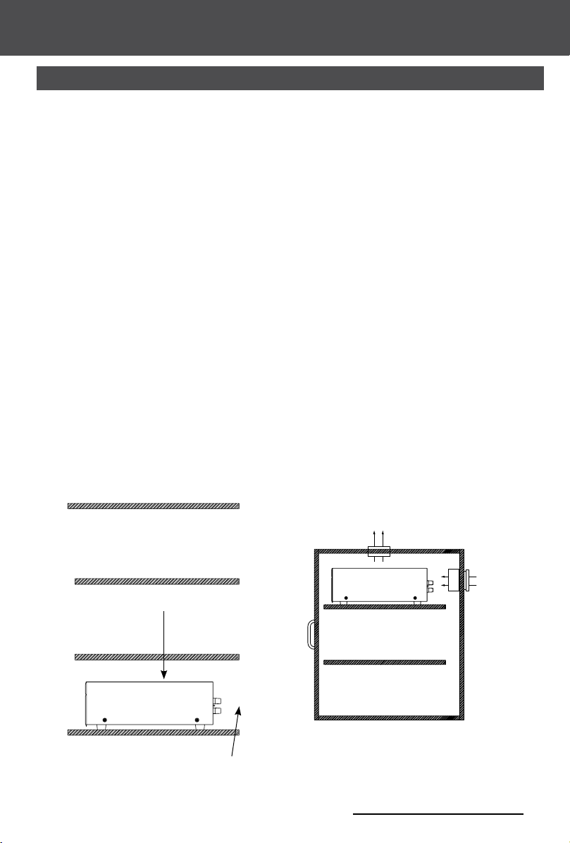
pLACEmENT
Place the Niles System Integration Amplier® on a at level surface like a table
or shelf. It should be placed upright so that its weight rests on the four attached
feet. Placing the weight of the amplier on the rear or front panel for even an
instant will result in damage to the amplier’s connectors and controls.
The Niles System Integration Amplier
®
, like any hi- component, will last much
longer if it is given adequate ventilation for proper cooling. When installing
the Niles System Integration Amplier
®
in a cabinet, be sure that the rear of
the cabinet is open to fresh air to provide proper cooling (see Figure 1). If the
cabinet’s design will not accommodate an open rear, install two small “boxer
fans” to provide continuous air ow into and out of the cabinet (see Figure 2).
Place the Niles System Integration Amplier
®
so that there is at least 7” of free
air space above the chassis. If the amplier is located on a carpeted surface,
place a board under the amplier’s feet. Do not block the ventilation holes on
the top and bottom of the Niles System Integration Amplier
®
.
CAUTION! When using low impedance speaker loads (less than 8 ohms Normal
Mode) refer to Figure 2 for proper placement.
Figure 1
Make sure that there is a minimum of 7” of free air
space above the amplier for proper ventilation.
Boxer Fan (55 CFM)
directly centered 7”
on top of the Amplifer.
Figure 2
Boxer Fan (55 CFM)
directly centered 2”
behind the Amplier.
If the cabinet rear is not open to fresh air or if you’re
using low impedance loads, install two “boxer fans”
to provide continuous air ow into and out of the
Allow a minimum of 2” of depth behind unit
to accommodate cables and connectors.
cabinet.
NILES AUDIO CORPORATION – 1-800-BUY-HIFI – 1-760-710-0992
7
Page 8
INSTALLATION CONSIdERATIONS
BRIDGED
LEFT RIGHT
This device complies with Part 15 of the FCC Rules.
Operation is subject to the following two conditions:
(1) this device may not cause harmful interference, and
(2) this device must accept any interference received,
including interference that may cause undesired
TURN-ON mOdES
The Niles System Integration Amplier® draws more current than a preamplier’s
switched AC outlet can safely supply. Also, your preamplier may “thump” at
dangerous volumes if the amplier is already on when the preamp turns on. It is
usually best to turn the amplier on only when it is needed. The Turn-On Mode
selector switch gives you three options for turning the amplier on and off. Audio
sense is the factory default setting.
Systems
Integration
Amplif ier
TURN ON MODE
AUDIO SENSE
CONSTANT
®
3-30V
AC/DC
TRIGGER
INPUT
12V
CONTROL
OUT
LEVELS
L R
FOR
BRIDGED
MODE
MAIN BUS
L
R
INPUT
BUS
OUTPUT
L
operation.
R
STEREO
CONSTANT - The auto turn-on circuitry is off. The front panel master power
switch operates the amplier. In is “On”, out is “Off”.
AUDIO SENSE - The master switch on the front panel must be in the “On”
position. The amplier is off when there is no audio signal present at either the
left or the right input, but the sensing circuitry is on. The turn-on sensing circuitry
looks for a tiny amount of audio signal present at any of the audio inputs. If it
detects a signal, the amplier is turned on. Once the audio signal stops, the
sensing circuit waits two minutes, then turns the amplier off.
3-24 VOLT AC/DC OPTO-ISOLATED VOLTAGE TRIGGER - The Power switch
on the front panel must be in the “On” position for the voltage trigger to function.
When a Trigger Plug is inserted into the rear panel connector and the sensing
circuitry detects a voltage, the amplier is turned on. Once the Trigger voltage is
turned off, the sensing circuit instantly turns the amplier off. The amplier is off
when there is no 3-24V AC or DC voltage detected at the trigger input. Voltage
triggers can be supplied by Niles automated switchers, some video projectors,
some surround sound processors, or something as simple as a 12 volt AC wall
adapter plugged into the switched outlet of your stereo receiver. Linear DC wall
adapters are not recommended; the long discharge time of the DC adapter’s lter
capacitor will delay the turn-off of the amplier. Trigger sources must be 3-24VAC
or DC, 20mA or greater.
INSTALLATION CONSIdERATIONS
8
WWW.NILESAUDIO.COM
Page 9

2 Channel, BridgaBle Power amPlifiers
INSTALLATION CONSIdERATIONS
BRIdGEd mOdE
The Niles System Integration Amplier® bridged mode switch allows you to create
a more powerful amplier by combining both channels into one (8 ohm minimum).
Stereo mode is the factory default setting.
In the bridged mode, connect the speakers to the left red positive terminal and
the right red positive terminal. In the bridged mode the right channel’s red terminal
becomes positive and the left channel’s red terminal becomes negative.
DO NOT USE THE BLACK NEGATIVE (-) TERMINALS. THE SIGNAL IS AT THE RED
POSITIVE (+) TERMINALS ONLY.
The line level input signal must connect to the left channel input of the amplier
when using bridged mode.
mULTIpLE SpEAkER LOAdS
The Niles System Integration Amplier® is stable into very low impedance loads.
This means you can safely operate three pairs of 8 ohm speakers (a 2.67 ohm load)
directly connected to the amplier. Note that the System Integration Amplier
®
does
not have on/off speaker switching built in. When the amplier is on, so are all of the
speakers.
Niles makes a number of different speaker selection and impedance matching
systems. Speaker selection systems allow each pair of speakers to be turned on
and off from your equipment location (or even via remote control). That way, you
know that the speakers in the bedroom are off so you can avoid waking a sleeping
spouse! These speaker selectors provide an easy way to terminate all of the wires
for more than three pairs. Testing and troubleshooting a new system is much easier
with the individual room labels and on/off switches of a Niles speaker selection
system. Additionally, Niles speaker selection systems offer impedance matching
features which will allow you to connect up to ten pairs of speakers to your Niles
System Integration Amplier
NILES AUDIO CORPORATION – 1-800-BUY-HIFI – 1-760-710-0992
®
.
9
Page 10

INSTALLATION CONSIdERATIONS
®
Systems Integration Amplif ier
SPEAKER 6
NILES
Niles Audio
Corporation,Inc.
Miami, Florida USA
AMPLIFIER
L+ L- R- R+
L+ L- R- R+ L+ L- R- R+ L+ L- R- R+ L+ L- R- R+ L+ L- R- R+
ON OFF
CONSTANT
PROTECTION
SPEAKER 5 SPEAKER 4 SPEAKER 3 SPEAKER 2
SPEAKER 1
L+ L- R- R+
CABLE ANd wIRE
It will be easier to recongure or troubleshoot your system in the future if you
label the cables and wires for their destination or source, rather than which
terminal of the Niles System Integration Amplier
®
The Niles System Integration Amplier
connects to your sources via shielded
®
they are connected to.
line level audio cables with RCA phono plugs. Use high quality cables with your
Niles amplier for the lowest possible noise and best overall performance. Your
Niles dealer can recommend the proper cable.
The Niles System Integration Amplier
®
connects to your speakers using 2
conductor speaker wire. For most applications, we recommend you use 16
or 18 gauge wire. For wiring runs longer than 80 feet, we recommend 14
gauge wire. The binding posts of the Niles System Integration Amplier
accommodate up to 12 gauge wire. Larger sizes can be accommodated by
attaching banana plugs to the wire. Note that the binding posts accept dual
banana or single banana connectors.
TECh TIp
Wire size is expressed by its AWG (American
Wire Gauge) number. The lower the number,
the larger the wire, i.e. twelve AWG is physically
larger than fourteen AWG.
10
WWW.NILESAUDIO.COM
®
will
Page 11

2 Channel, BridgaBle Power amPlifiers
CLASS 2 WIRING
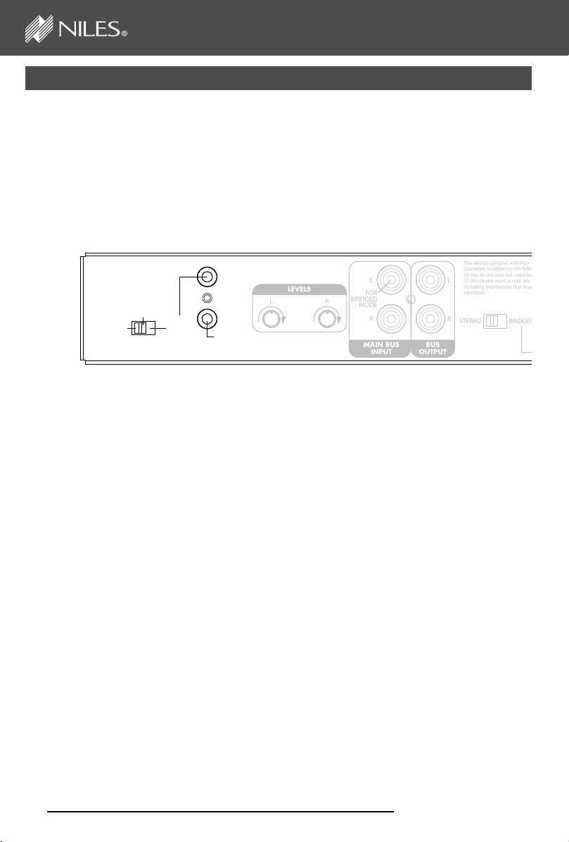
FRONT ANd REAR pANEL dETAILS
Front panel “Master Power” switch turns off the
entire amplier, including the Turn-On circuitry.
SI-250
Systems Integration Amplif ier
3.5 mm mini-jack for
voltage input
SI-2 50
Systems
Integration
Amplif ier
CONSTANT
®
TURN ON MODE
AUDIO SENSE
3-30V
AC/DC
TRIGGER
INPUT
“Turn-On Mode”
switch
®
Main Inputs enable you to
route a stereo line level source
to the amplier.
This Class B digital apparatus complies with Canadian
ICES-003.
Cet appareil numérique de la classe B est conforme à la
norme NMB-003 du Canada.
12V
CONTROL
OUT
LEVELS
L R
BRIDGED
MODE
MAIN BUS
L
FOR
R
INPUT
Cascade Outputs of the
main input enable you
to daisy chain multiple
ampliers
This device complies with Part 15 of the FCC Rules.
Operation is subject to the following two conditions:
(1) this device may not cause harmful interference, and
L
(2) this device must accept any interference received,
including interference that may cause undesired
operation.
R
STEREO BRIDGED
BUS
OUTPUT
Bridge mode switch
LEFT
3.5 mm mini-jack for
12V DC control output
Level Adjustment screws enable you to
preset the maximum system volume (or
match levels with another amplier)
NILES AUDIO CORPORATION – 1-800-BUY-HIFI – 1-760-710-0992
11
Page 12

FRONT ANd REAR pANEL dETAILS
Power LED illuminates to conrm
the amplier is connected to a
live AC power outlet and that the
master power switch is on
Bicolor Status LED illuminates
“green” when the amplier circuitry
has been turned on by the Turn-On
circuits, and illuminates “red” to
indicate activation of the amplier’s
built-in protection circuitry
12
Minimum impedance:
2.66 Ω (stereo mode)
4 Ω (bridged mode)
Niles Audio, Carlsbad, California, USA
Designed and Engineered in the U.S.A. Made in China
Binding posts for
speaker connections
Replaceable main
power fuse
Serial No.
T5AL, 250V
100-120V / 220-240V~
50 / 60Hz 200W
CAUTION: replace only with same type and rating of fuse.
ATTENTION: remplacer uniquement avec le même type
et calibre du fusible.
IEC receptacle for
AC power cord
WWW.NILESAUDIO.COM
Page 13

2 Channel, BridgaBle Power amPlifiers
L
R
BUS
OUTPUT
FOR
BRIDGED
MODE
L
R
MAIN BUS
INPUT
STEREO BRIDGED
LEFT RIGHT
This device complies with Part 15 of the FCC Rules.
Operation is subject to the following two conditions:
(1) this device may not cause harmful interference, and
(2) this device must accept any interference received,
including interference that may cause undesired
operation.
INSTALLATION
SETTING ThE TURN-ON mOdE SwITCh
The Niles System Integration Amplier® has three turn-on modes. Select which
mode you desire by sliding the mode switch. See Installation Considerations on
page 6 for more information about each of the turn-on modes. Audio sense is
the factory default setting.
Systems
Slide the switch with
your ngernail or a 1/8”
slotted screwdriver blade
Integration
Amplif ier
CONSTANT
®
TURN ON MODE
AUDIO SENSE
3-30V
AC/DC
TRIGGER
INPUT
12V
CONTROL
OUT
LEVELS
L R
TIP: To conserve energy set the TURN ON mode to
either AUDIO SENSE or TRIGGER INPUT. Use of the
CONSTANT mode will prevent the amplifier from
turning off when not in use wasting energy.
CONTROL OUTpUT
This terminal provides a 12V DC signal
suitable for triggering Niles automated
switchers, some motorized screens, some
electric curtain controls, etc. The trigger
voltage is present only when the amplier is
active or “on”. When the amplier turns “off”,
the 12 Volt signal is off.
STEP DESCRIPTION
1. Check the requirements of the device you
want to control.
2. Connect the 3.5 mm Jack to the control
output maintaining proper polarity
(tip = +).
STEP DESCRIPTION
NILES AUDIO CORPORATION – 1-800-BUY-HIFI – 1-760-710-0992
The control output has a maximum
current capability of 12V DC 150 mA.
Niles makes an accessory cable plug
FG00933.
13
Page 14

INSTALLATION
SpEAkER wIRE CONNECTIONS
CAUTION! All speaker wire connections must be made with the amplier off.
Banana Plugs
Bare Wire
Unscrew the red or
black plastic knob,
insert the bare wire
end into the opening,
and then tighten the
knob until the wire is
securely clamped
There are many types of
banana plugs, some crimp,
some solder. The Niles
gold banana plug has 3
quick-connect binding
post for the bare wire on
the body of the plug. A
banana plug is simply
inserted into the jack at
the end of the amplier’s
binding post. Dual banana
plugs will t the binding
post.
STEP DESCRIPTION
If you label the wires for their destination,
1. Label all wires.
rather than which terminal of the Niles
System Integration Amplifier
®
they
are connected to, it will be easier to
reconfigure your system in the future.
A. Split the speaker wire insulation so that
at least two inches of each conductor are
separated.
2. Connect one stripped wire
end or banana plug to the
black terminal and one to
the red terminal.
B. Strip one half inch of insulation from
the end of each conductor of the speaker
wire.
C. Attach banana plugs or twist the
strands of wire together and insert them
into the appropriate binding post.
CAUTION! Avoid even a single strand of wire touching the chassis or another
connector.
14
WWW.NILESAUDIO.COM
Page 15

2 Channel, BridgaBle Power amPlifiers
INSTALLATION
LINE LEvEL AUdIO INpUT
CAUTION! The amplier must be off whenever you make changes to the input
connections.
STEP DESCRIPTION
1. Label all of the interconnecting cables
for the sources they connect to.
Use audio patch cables with RCA
phono plugs attached to the ends.
Connect outputs from your sources
to inputs on the amplifier. Never
2. Connect the sources by inserting the
RCA plugs into the amplifier’s jacks.
CASCAdE AUdIO OUTpUTS
The “Cascade Audio Outputs” enable you to connect another amplier to
your preamplier output. The connectors are gold-plated RCA phono jacks.
Connect them to another amplier’s inputs with a standard audio patch cable.
The outputs are not buffered; if you wish to daisy-chain more than 5 Niles
System Integration Amplier
distribution amplier. A single AVDA-3 will allow you to daisy-chain 5 ampliers
from each of its three outputs, allowing for as many as 30 Niles System
Integration Amplier
your preamp has a vacuum tube output stage, you must use a Niles AVDA-3 to
drive more than a single Niles System Integration Amplier
®
®
ampliers you will need a Niles AVDA-3 buffered
models to be fed from the same master preamplier. If
connect a source or preamplifier’s
input (e.g., record inputs) to
the inputs of your Niles System
Integration Amplifier
®
.
®
.
NILES AUDIO CORPORATION – 1-800-BUY-HIFI – 1-760-710-0992
15
Page 16

INSTALLATION
AC pOwER pLUG
STEP DESCRIPTION
1. Plug the female IEC socket of the
supplied AC power cord (the supplied
power cord is designed for 120V AC
wall outlets), or use an appropriate
IEC AC power cord to match the
electrical wall outlet you are using
(e.g. 240V AC), into the IEC receptacle
Just like a computer or printer, the
Niles System Integration Amplifier
has an AC cord which unplugs
either at the amp or at the wall for
your convenience.
on the rear of the amplifier.
®
2. Plug the male end of the AC power
cord into a correctly grounded wall
outlet.
CAUTION! Typically a preamp/receiver’s switched outlet is not rated for a power
amplier. The SI- 250, the SI-2100 and the SI-2150 draw 200 watts, 300 watts,
and 400 watts maximum from an AC wall outlet respectively. Use a dedicated
AC wall outlet along with the amplier’s auto turn on circuit to ensure adequate
power.
If you use a grounded power strip,
surge suppressor or extension
cord, verify that proper ground is
maintained.
16
WWW.NILESAUDIO.COM
Page 17

2 Channel, BridgaBle Power amPlifiers
OpERATION
pOwER SwITCh
The front panel switch is a master or “vacation” power switch. No matter which
turn-on mode you have selected, the master power switch will turn off all
circuitry including the sensing circuitry. If you will not be using the amplier for
an extended period of time, turn the master power switch “Off” (push button
switch out). When you would like to return to normal operation, turn the switch
“On” (push button switch in).
Important Notes: Equipment is not completely disconnected from main power
source when power switch is in the “OFF” position.
pOwER LEd
The power LED indicates that the AC cord is plugged into a working AC power
receptacle and that the power switch is in the “On” position.
BICOLOR STATUS LEd
The bicolor Status LED illuminates “green” when the amplier circuitry has been
turned on by the Turn-On circuits, and illuminates “red” to indicate activation of
the amplier’s built-in protection circuitry due to either a fault in the wiring or the
speaker, or with the Niles System Integration Amplier
®
itself.
LEvEL AdjUSTmENT SCREwS
The rear panel level adjustment screws allow you to adjust the level of the Niles
System Integration Amplier
®
relative to other ampliers in your system. Use
a 1/8” slotted screwdriver to adjust the screws. If the Niles System Integration
Amplier
®
is the only amplier in your system, leave the screws at their factory
default setting (12:00 position).
CLEANING ANd mAINTENANCE
The internal parts of the Niles System Integration Amplier® are electronic
and require no maintenance. Once a year it is appropriate to twist the RCA
connectors on each input to remove corrosion and improve conductivity. You
can clean the amplier with soft cloth or paper towel dampened with water or a
mild detergent. Do not use any spray-type, abrasive cleaners on the amplier.
NILES AUDIO CORPORATION – 1-800-BUY-HIFI – 1-760-710-0992
17
Page 18

TROUBLEShOOTING GUIdE
When there is a problem, consult this guide rst. If the problem persists, or you
have additional questions, call your local Niles dealer or Niles Technical Support
at 1-800-BUY-HIFI (289-4434) or (760) 710-0992. The most common problems
relate to hook up. Call from your telephone extension nearest the system.
Symptom Possible Causes and Test Procedure
Short circuit or loose wire at the speaker or amplifier terminals.
Check that the connections are secure and that there are no
loose strands of wire crossing from the positive to the negative
terminals at the back of the amplifier and /or the speaker.
Short circuit or a break in the speaker wire. Disconnect the
No sound on
one channel
speaker wire at both ends, separate the 2 conductors at both
ends and test with a meter for a short circuit. If there is no
short,
connect the two conductors at one end and test with a meter for
continuity.
Speaker is not working. Connect the speaker to a channel that
plays another speaker. Audio cable to input is bad. Connect
another cable that is known to be good.
No sound on
both channels
Hum from the
speakers
18
Audio cable to the main inputs is bad. Connect another cable that
is known to be good.
Hum may be caused by a ground loop between two of the other
components in the system. To test for another ground loop, try
reversing the ac plugs of each of the components in the system.
WWW.NILESAUDIO.COM
Page 19

2 Channel, BridgaBle Power amPlifiers
TROUBLEShOOTING GUIdE
Symptom Possible Causes and Test Procedure
Hum from the speakers
Amp will not turn on
Bass sound is weak
and the stereo image
is “phasey” or “blurry”
sounding in one room
Check for faulty cables, faulty source material, an
ungrounded phono system or a defective component.
AC power cord must be plugged into a working outlet.
Master power switch must be on.
The loudspeakers are wired out of phase. Reverse the
connections at the back of one speaker.
NILES AUDIO CORPORATION – 1-800-BUY-HIFI – 1-760-710-0992
19
Page 20

SpECIFICATIONS
SI-250 SI-2100 SI-2150
Design Principle
Continuous
Average Power
Output
Continuous
Average Power
Output Bridged
Frequency
Response
Signal to Noise
Ratio
Total Harmonic
Distortion
Channel
Separation
Fully discrete, high
current bridgeable
stereo amplifier
50 watts RMS per
channel into 8 Ohms,
100 watts RMS per
channel into 4 Ohms
(all channels driven)
225 wats RMS per
channel into 8 Ohms
Bandwidth from 5 Hz
to 25 kHz (=0dB/-3B)
20Hz to 20kHz
unweighted > 102 dB
0.2% THD from
20 Hz to 20 kHz
@ 1kHz >70dB @ 1kHz >70dB @ 1kHz >70dB
Digital, high current
bridgeable stereo
amplifier
100 watts RMS per
channel into 8 Ohms,
220 watts RMS per
channel into 4 Ohms
(all channels driven)
400 wats RMS per
channel into 8 Ohms
Bandwidth from 5 Hz
to 25 kHz (=0dB/-3B)
20Hz to 20kHz
unweighted > 102 dB
0.2% THD from
20 Hz to 20 kHz
Digital, high current
bridgeable stereo
amplifier
150 watts RMS per
channel into 8 Ohms,
270 watts RMS per
channel into 4 Ohms
(all channels driven)
550 wats RMS per
channel into 8 Ohms
Bandwidth from 5 Hz
to 25 kHz (=0dB/-3B)
20Hz to 20kHz
unweighted > 102 dB
0.2% THD from
20 Hz to 20 kHz
Overall
Dimensions
Weight
AC Mains:
20
17 ¼” (43.81 cm) wide
2 ¼” (5.6 cm) high (including feet)
13 ½” (34.35 cm) deep
10.7 lb., 4.8 kg. 10.8 lb., 4.9 kg. 10.8 lb., 4.9 kg.
100-120/220-240 V~,
50/60 Hz, 200 W
100-120/220-240 V~,
50/60 Hz, 300 W
100-120/220-240 V~,
50/60 Hz, 400 W
WWW.NILESAUDIO.COM
Page 21

2 Channel, BridgaBle Power amPlifiers
BY PHONE (IN USA)
1-800-BUY-HIFI (289-4434)
BY PHONE (OUtSIdE USA)
1-760-710-0992
CUStOmEr SErvICE HOUrS
8:00 AM to 5:30 PM PT
tECHNICAl SUPPOrt HOUrS
6:00 AM to 4:00 PM PT
ON tHE wEB
www.nilesaudio.com
EmAIl tECHNICAl SUPPOrt
techsupport@nilesaudio.com
EmAIl fOr PrOdUCt SUggEStIONS
productsuggestions@nilesaudio.com
NILES AUDIO CORPORATION – 1-800-BUY-HIFI – 1-760-710-0992
21
Page 22

LImITEd wARRANTy
Niles Audio Corporation (“NILES”) warrants to the original retail purchaser only that this product will be free of manufacturing defects
in material and workmanship for the following periods and subject to the limitations and exclusions set forth below:
Lifetime Warranty
All Passive Amplifier Products (those not requiring AC or battery power).
Ten years from the date of purchase
All Other Passive Products (those not requiring AC or battery power).
Two years from the date of purchase
All Active Products (those requiring AC or battery power).
This warranty is not transferable to subsequent purchasers of the product. To obtain warranty service, contact the authorized dealer
where you purchased your product or take the unit to the nearest authorized NILES dealer (with proof of purchase – claims made
without proof of purchase will be denied) who will test the product and if necessary, forward it to NILES for service. If there are no
authorized NILES dealers in your area, you must contact NILES to receive a factory Return Authorization Number. DO NOT RETURN
ANY UNIT WITHOUT FIRST RECEIVING WRITTEN AUTHORIZATION AND SHIPPING INSTRUCTIONS FROM NILES.
Upon examination, NILES will, at its sole option and expense, repair or replace any product found to be defective. NILES will return
the repaired or replaced unit to you via its usual shipping method from the factory to your address in the United States of America or
Canada only. Any shipping costs for addresses outside of the United States or Canada shall be the responsibility of the purchaser.
In the event that this model is no longer available and cannot be repaired effectively, NILES, at its sole option, may replace it with
a different model of equal or greater value, or refund the original purchase price paid. THE FOREGOING ARE YOUR EXCLUSIVE
REMEDIES FOR BREACH OF WARRANTY.
This Warranty does not include service or parts to repair damage caused by improper use or handling, including but not limited to
damage caused by accident, mishandling, improper installation, commercial use, abuse, negligence, or normal wear and tear, or any
defect caused by repair to the product by anyone other than NILES.
This warranty does not cover reimbursement for your costs of removing and transporting the product for warranty service
evaluation, or installation of any replacement product provided under this warranty.
This Warranty will be void if:
•the Serial Number on the product has been removed, tampered with or defaced.
• the product was not purchased from an authorized dealer or reseller.
THE FOREGOING WARRANTIES ARE EXCLUSIVE AND IN LIEU OF ALL OTHER EXPRESSED AND IMPLIED WARRANTIES.
NILES EXPRESSLY DISCLAIMS ALL SUCH OTHER WARRANTIES, INCLUDING BUT NOT LIMITED TO IMPLIED
WARRANTIES OF MERCHANTABILITY, FITNESS FOR A PARTICULAR PURPOSE AND NON-INFRINGEMENT, WITH RESPECT
TO THE PRODUCT. TO THE MAXIMUM EXTENT PERMITTED BY LAW, NILES SHALL NOT BE RESPONSIBLE FOR ANY
INCIDENTAL OR CONSEQUENTIAL DAMAGES EXCEPT TO THE EXTENT PROVIDED (OR PROHIBITED) BY APPLICABLE
LAW, EVEN IF NILES HAS BEEN ADVISED OF THE POSSIBILITY OF SUCH DAMAGES.
Notwithstanding the above, if you qualify as a “consumer” under the Magnuson-Moss Warranty Act, or applicable state laws, then
you may be entitled to any implied warranties allowed by law for the Warranty Period. Further, some states do not allow limitations
on how long an implied warranty lasts or allow the exclusion or limitation of consequential damages, so such limitations may not
apply to you. This warranty gives you specific legal rights, and you may also have other rights which vary from state to state.
For the name of your nearest authorized NILES dealer, contact: THE AVC GROUP, 1969 Kellogg Avenue, Carlsbad, CA 92008, or call
(800) BUY-HIFI (289-4434) or (760) 710-0992. Please be advised that NILES only sells its products via the Internet through a select
group of authorized Internet dealers. These are listed on our website at www.nilesaudio.com. Products offered on the Internet
through unauthorized Internet dealers are not covered by the NILES warranty and may be either:
1) goods acquired on a secondary or grey market
2) counterfeit or stolen goods
3) damaged, or defective goods
Please fill in your product information and retain for your records.
Model ______________________ Serial No. _____________________________________________ Purchase Date ______________
ATTENTION: TO OUR VALUED CONSUMERS:
To insure that consumers obtain quality pre-sale and after-sale support and service, NILES products are sold exclusively through
authorized dealers. This warranty is VOID if the products have been purchased from an unauthorized dealer.
22
WWW.NILESAUDIO.COM
Page 23

NOTES
2 Channel, BridgaBle Power amPlifiers
NILES AUDIO CORPORATION – 1-800-BUY-HIFI – 1-760-710-0992
23
Page 24

1690 Corporate Circle, Petaluma, CA 94954
1-760-710-0992
1-800-BUY-HIFI – www.nilesaudio.com
©2012 Core Brands, LLC. All rights reserved. Niles and the Niles logos are registered
trademarks of Core Brands, LLC. All other trademarks are the property of their respective
owners. We reserve the right to change specifications, descriptions and prices without notice.
The technical and other information contained herein is not intended to set forth all technical
and other specifications. Designed and engineered in the USA. 9901253 Rev D
 Loading...