

Nikon Total Station DTM-322 Instruction Manual

Total Station
DTM-322
Instruction Manual
Version A 1.0.0
Part Number C232E
April 2009
www.trimble.com

Contact Information
Trimble Navigation Limited
Engineering and Construction Division
5475 Kellenburger Road
Dayton, Ohio 45424-1099
USA
800-538-7800 (toll free in USA)
+1-937-245-5600 Phone
+1-937-233-9004 Fax
www.trimble.com
Legal Notices
Copyright and Trademarks
© 2007-2008, Nikon-Trimble Co. Limited. All rights reserved.
All trademarks are the property of their respective owners.
It is prohibited to alter this manual in part or whole without express
permission.
The contents of this manual are subject to change without notice.
Although every effort has been made to ensure the accuracy of this
manual, please contact your dealer if you find anything in it that is
incorrect or unclear.
Release Notice
This is the April 2009 (Revision A) release of the Total Station DTM322 Instruction Manual. It applies to software release version 1.0.0 for
the Total Station DTM-322.
Manufacturer
Nikon-Trimble Co., Ltd.
Technoport Mituiseimei Bldg.
16-2, Minamikamata 2-chome, Ota-ku
Tokyo 144-0035 Japan
Notices
USA
FCC 15B Class B satisfied.
This equipment has been tested and found to comply with the limits for
a Class B digital device, pursuant to Part 15 of the FCC Rules. These
limits are designed to provide reasonable protection against harmful
interference in a residential installation. This equipment generates, uses
and can radiate radio frequency energy and, if not installed and used in
accordance with the instructions, may cause harmful interference to
radio communications. However, there is no guarantee that interference
will not occur in a particular installation.
If this equipment does cause harmful interference to radio or television
reception, which can be determined by turning the equipment off and
on, the user is encouraged to try to correct the interference by one or
more of the following measures:
– Reorient or relocate the receiving antenna.
– Increase the separation between the equipment and receiver.
– Connect the equipment into an outlet on a circuit different from that
to which the receiver is connected.
– Consult the dealer or an experienced radio/TV technician for help.
European Union
EU EMC Directive satisfied.
Authorized Representative in Europe
Trimb le GmbH
Am Prime Parc 11
65479 Raunheim, Germany
Canada
This Class B digital apparatus meets all requirements of the Canadian
Interference-Causing Equipment Regulations.
Cet appareil numérique de la Class B respecte toutes les exigences du
Règlement sur le matériel brouilleur du Canada.
Tai wa n
Battery Recycling
Requirements
The product contains a removable battery.
Taiwanese regulations require that waste batteries
are recycled.
Notice to Our European Union Customers
For product recycling instructions and more information,
please go to:
www.trimble.com/environment/summary.html
Recycling in Europe
To recycle Trimble WEEE,
call: +31 497 53 2430,
and ask for the “WEEE associate,”
or mail a request for recycling instructions to:
Trimb le Europe BV
c/o Menlo Worldwide Logistics
Meerheide 45
5521 DZ Eersel, NL
C
Warning – This equipment has been certified to
comply with the limits for a Class B digital device,
pursuant to Subpart B of Part 15 of FCC Rules.
Only peripherals (computer input/output devices,
terminals, printers, etc.) certified to comply with the
Class B limits may be attached to this equipment.
Operation with non-certified personal computer
and/or peripherals is likely to result in interference to
radio and TV reception. The connection of a nonshielded equipment interface cable to this
equipment will invalidate the FCC Certification of
this device and may cause interference levels which
exceed the limits established by the FCC for this
equipment.
You are cautioned that changes or modifications not
expressly approved by the party responsible for
compliance could void your authority to operate the
equipment.

Safety 1
In this chapter:
Introduction
LED Safety
Warnings and Cautions
Total Station DTM-322 Instruction Manual iii

Introduction
For your safety, read this instruction manual carefully and thoroughly before using
the DTM-322 instrument. Although Nikon products are designed for maximum
safety, using them incorrectly or disregarding the instructions can cause personal
injury or property damage.
You should also read the documentation for any other equipment that you use with a
DTM-322 instrument.
Note – Always keep the manual near the instrument for easy reference.
LED Safety
The DTM-322 is a Class 1 LED instrument.
Class 1 LED instruments do not require any special precautions, signage or training
for LED safety.
Table 1.1 Specifications for LED emission
Wave length 850 nm
Drive method CW
Output power < 200 µW
Repetition rate 15 KHz
Table 1.2 Safety class
E.U. EN60825-1/Am.2:2001 (IEC60825-1/Am.2:2001), class 1
Japan JIS C6802:2005, class 1
iv Total Station DTM-322 Instruction Manual

Warnings and Cautions
The following conventions are used to indicate safety instructions:
C
C
Warnings
C
C
C
WARNING – Warnings alert you to situations that could cause death or serious injury.
CAUTION – Cautions alert you to situations that could cause injury or property damage.
Always read and follow the instructions carefully.
Before using the instrument, read the following warnings and follow the instructions
that they provide:
WARNING – Never look at the sun through the telescope. If you do, you may damage or lose
your eyesight.
WARNING – The DTM-322 is not designed to be explosion-proof. Do not use the instrument in
coal mines, in areas contaminated with coal dust, or near other flammable substances.
WARNING – Never disassemble, modify, or repair the instrument yourself. If you do, you may
receive electric shocks or burns, or the instrument may catch fire. You may also impair the
accuracy of the instrument.
C
C
C
C
C
WARNING – To charge the battery, use only the battery charger that is supplied with the
instrument. Do NOT use any other charger or you may cause the battery to catch fire or
rupture.
WARNING – Do not cover the battery charger while the battery is being recharged. The
charger must be able to dissipate heat adequately. Coverings such as blankets or clothing can
cause the charger to overheat.
WARNING – Avoid recharging the battery in humid or dusty places, in direct sunlight, or near
heat sources. Do not recharge the battery when it is wet. If you do, you may receive electric
shocks or burns, or the battery may overheat or catch fire.
WARNING – You should take care not to short circuit the contacts. Short circuits can cause the
battery to catch fire or burn you.
WARNING – Never burn or heat the battery. Doing so may cause the battery to leak or rupture.
A leaking or ruptured battery can cause serious injury.
Total Station DTM-322 Instruction Manual v

C
WARNING – Before storing the battery or battery charger, cover the contact points with
insulation tape. If you do not cover the contact points, the battery or charger may short circuit,
causing fire, burns, or damage to the instrument.
C
Cautions
C
C
C
C
WARNING – The battery is not itself waterproof. Do not get the battery wet when it is removed
from the instrument. If water seeps into the battery, it may cause a fire or burns.
Before using the instrument, read the following cautions and follow the instructions
that they provide:
CAUTION – Do not use controls or adjustments, or carry out any procedures, other than those
specified in this document. Otherwise you may be exposed to hazardous radiation.
CAUTION – The tops of the tripod ferrules are very sharp. When handling or carrying the
tripod, take care to avoid injuring yourself on the ferrules.
CAUTION – Before carrying the tripod or the instrument in the carrying case, check the
shoulder strap and its clasp. If the strap is damaged or the clasp is not securely fastened, the
carrying case may fall, causing personal injury or instrument damage.
CAUTION – Before setting up the tripod, make sure that no-one’s hands or feet are underneath
it. When the legs of the tripod are being driven into the ground, they could pierce hands or feet.
C
C
C
C
vi Total Station DTM-322 Instruction Manual
CAUTION – After mounting the instrument on the tripod, securely fasten the thumb screws on
the tripod legs. If the thumb screws are not securely fastened, the tripod may collapse, causing
personal injury or instrument damage.
CAUTION – After mounting the instrument on the tripod, securely fasten the clamp screw on
the tripod. If the clamp screw is not securely fastened, the instrument may fall off the tripod,
causing personal injury or instrument damage.
CAUTION – Securely fasten the leveling base clamp knob. If the knob is not securely fastened,
the leveling base may come loose or fall off when you lift the instrument, causing personal
injury or instrument damage.
CAUTION – Do not stack objects on the plastic carrying case, or use it as a stool. The plastic
carrying case is unstable and its surface is slippery. Stacking or sitting on the plastic carrying
case may cause personal injury or instrument damage.

C
CAUTION – The system in the instrument might stop functioning to avoid any errors in
measurement when the instrument detects strong electromagnetic waves. If this happens, turn
off the instrument and remove the source of the electromagnetic wave. Then turn on the
instrument to resume work.
Total Station DTM-322 Instruction Manual vii

viii Total Station DTM-322 Instruction Manual

Contents
Safety . . . . . . . . . . . . . . . . . . . . . . . . . . . . . . . . . . . . . . iii
Introduction . . . . . . . . . . . . . . . . . . . . . . . . . . . . . . . . . . . . . . . . . iv
LED Safety . . . . . . . . . . . . . . . . . . . . . . . . . . . . . . . . . . . . . . . . . iv
Warnings and Cautions . . . . . . . . . . . . . . . . . . . . . . . . . . . . . . . . . . . . v
Warnings . . . . . . . . . . . . . . . . . . . . . . . . . . . . . . . . . . v
Cautions . . . . . . . . . . . . . . . . . . . . . . . . . . . . . . . . . . vi
1 Introduction . . . . . . . . . . . . . . . . . . . . . . . . . . . . . . . . . . . . 1
Welcome . . . . . . . . . . . . . . . . . . . . . . . . . . . . . . . . . . . . . . . . . . 2
Parts of the Instrument . . . . . . . . . . . . . . . . . . . . . . . . . . . . . . . . . . . . 3
Maintenance . . . . . . . . . . . . . . . . . . . . . . . . . . . . . . . . . . . . . . . . 5
2 Preparation . . . . . . . . . . . . . . . . . . . . . . . . . . . . . . . . . . . . 7
Unpacking and Packing the Instrument . . . . . . . . . . . . . . . . . . . . . . . . . . . . 8
Unpacking . . . . . . . . . . . . . . . . . . . . . . . . . . . . . . . . . 8
Packing . . . . . . . . . . . . . . . . . . . . . . . . . . . . . . . . . . . 8
Charging the Battery . . . . . . . . . . . . . . . . . . . . . . . . . . . . . . . . . . . . . 8
Detaching and Re-Attaching the Battery Case. . . . . . . . . . . . . . . . . . . . . . . . . . 11
Detaching the battery case . . . . . . . . . . . . . . . . . . . . . . . . . . . 11
Attaching the battery case . . . . . . . . . . . . . . . . . . . . . . . . . . .11
Setting Up the Tripod . . . . . . . . . . . . . . . . . . . . . . . . . . . . . . . . . . . . 12
Centering . . . . . . . . . . . . . . . . . . . . . . . . . . . . . . . . . . . . . . . . . . 13
Centering using the optical plummet . . . . . . . . . . . . . . . . . . . . . . .13
Leveling . . . . . . . . . . . . . . . . . . . . . . . . . . . . . . . . . . . . . . . . . . 14
Sighting . . . . . . . . . . . . . . . . . . . . . . . . . . . . . . . . . . . . . . . . . . 15
Setting Up the Prism Reflector . . . . . . . . . . . . . . . . . . . . . . . . . . . . . . . . 16
Adjusting the height of the tribrach adapter . . . . . . . . . . . . . . . . . . . . . 16
Changing the direction of the prism . . . . . . . . . . . . . . . . . . . . . . .17
Setting the prism constant . . . . . . . . . . . . . . . . . . . . . . . . . . .17
Setting the position of the target plate . . . . . . . . . . . . . . . . . . . . . . .17
Face-1/Face-2 Measurements . . . . . . . . . . . . . . . . . . . . . . . . . . . . . . . . . 18
3 Getting Started . . . . . . . . . . . . . . . . . . . . . . . . . . . . . . . . . . 19
Turning the Instrument On and Off . . . . . . . . . . . . . . . . . . . . . . . . . . . . . . 20
Turning on the instrument . . . . . . . . . . . . . . . . . . . . . . . . . . .20
Turning off the instrument . . . . . . . . . . . . . . . . . . . . . . . . . . .20
Selecting a Language . . . . . . . . . . . . . . . . . . . . . . . . . . . . . . . . . . . . 21
Changing Regional Configuration Pre-sets . . . . . . . . . . . . . . . . . . . . . . . . . . . 22
Display and Key Functions . . . . . . . . . . . . . . . . . . . . . . . . . . . . . . . . . . 24
Status bar . . . . . . . . . . . . . . . . . . . . . . . . . . . . . . . . . . 26
Adjusting lighting and sound levels. . . . . . . . . . . . . . . . . . . . . . . .27
[DSP] key . . . . . . . . . . . . . . . . . . . . . . . . . . . . . . . . . .28
[MODE] key. . . . . . . . . . . . . . . . . . . . . . . . . . . . . . . . . .29
[COD] key . . . . . . . . . . . . . . . . . . . . . . . . . . . . . . . . . .30
[HOT] key . . . . . . . . . . . . . . . . . . . . . . . . . . . . . . . . . .31
Bubble indicator . . . . . . . . . . . . . . . . . . . . . . . . . . . . . . .33
[USR] keys . . . . . . . . . . . . . . . . . . . . . . . . . . . . . . . . . .33
[DAT] key. . . . . . . . . . . . . . . . . . . . . . . . . . . . . . . . . . . 35
Total Station DTM-322 Instruction Manual ix

Contents
List Display . . . . . . . . . . . . . . . . . . . . . . . . . . . . . . . . . . . . . . . . . 35
Inputting Data . . . . . . . . . . . . . . . . . . . . . . . . . . . . . . . . . . . . . . . . 36
Entering a point name or number . . . . . . . . . . . . . . . . . . . . . . . . .36
Entering a code . . . . . . . . . . . . . . . . . . . . . . . . . . . . . . .39
Advanced feature: Searching for a code by using the first character . . . . .40
Entering values in feet and inches . . . . . . . . . . . . . . . . . . . . . . . .41
Jobs . . . . . . . . . . . . . . . . . . . . . . . . . . . . . . . . . . . . . . . . . . . . 42
Creating a new job . . . . . . . . . . . . . . . . . . . . . . . . . . . . . .42
Measuring Distances . . . . . . . . . . . . . . . . . . . . . . . . . . . . . . . . . . . . . 43
Sighting a prism reflector. . . . . . . . . . . . . . . . . . . . . . . . . . . . 43
Measuring distances. . . . . . . . . . . . . . . . . . . . . . . . . . . . . .44
Measurement settings . . . . . . . . . . . . . . . . . . . . . . . . . . . . .45
4 Applications . . . . . . . . . . . . . . . . . . . . . . . . . . . . . . . . . . . 47
HA Reset and Angle Operations. . . . . . . . . . . . . . . . . . . . . . . . . . . . . . . . 48
Setting the horizontal angle to 0 . . . . . . . . . . . . . . . . . . . . . . . . .48
Entering the horizontal angle . . . . . . . . . . . . . . . . . . . . . . . . . .48
Recording a foresight point after repeat angle measurement . . . . . . . . . . . . . .48
Horizontal angle hold . . . . . . . . . . . . . . . . . . . . . . . . . . . . .49
Station Setup . . . . . . . . . . . . . . . . . . . . . . . . . . . . . . . . . . . . . . . . 49
Setting up a station with known coordinates or azimuth. . . . . . . . . . . . . . . .50
Setting up a station using multiple point resection . . . . . . . . . . . . . . . . . . 53
Advanced feature: Viewing and deleting a measurement in resection . . . . .55
Setting up the station quickly without coordinates . . . . . . . . . . . . . . . . . .56
Determining station elevation . . . . . . . . . . . . . . . . . . . . . . . . . .56
Checking and resetting the backsight direction . . . . . . . . . . . . . . . . . . .57
Two-point resection along a known line . . . . . . . . . . . . . . . . . . . . . .58
Stakeout . . . . . . . . . . . . . . . . . . . . . . . . . . . . . . . . . . . . . . . . . . 60
Specifying the stakeout point by angle and distance . . . . . . . . . . . . . . . . .61
Specifying the stakeout point by coordinates . . . . . . . . . . . . . . . . . . . .62
Advanced feature: Specifying a stakeout list by range input . . . . . . . .64
DivLine S-O . . . . . . . . . . . . . . . . . . . . . . . . . . . . . . . . .65
RefLine S-O . . . . . . . . . . . . . . . . . . . . . . . . . . . . . . . . .66
Program Key . . . . . . . . . . . . . . . . . . . . . . . . . . . . . . . . . . . . . . . . 67
Measuring distance and offset values along a specified line . . . . . . . . . . . . . .67
Measuring distance and offset values on the arc-curve . . . . . . . . . . . . . . . .69
Remote distance measurement. . . . . . . . . . . . . . . . . . . . . . . . . .71
Measuring remote elevation . . . . . . . . . . . . . . . . . . . . . . . . . . .73
Measuring distance and offset values on the vertical plane . . . . . . . . . . . . . . .74
Measuring distance and offset values on the slope . . . . . . . . . . . . . . . . . .76
Recording Measurement Data. . . . . . . . . . . . . . . . . . . . . . . . . . . . . . . . . 77
Recording data from any observation screen . . . . . . . . . . . . . . . . . . . .77
Outputting data to the COM port . . . . . . . . . . . . . . . . . . . . . . . . .78
Measuring Offsets . . . . . . . . . . . . . . . . . . . . . . . . . . . . . . . . . . . . . . 79
Measuring taped offsets . . . . . . . . . . . . . . . . . . . . . . . . . . . .79
Measuring angle offsets . . . . . . . . . . . . . . . . . . . . . . . . . . . .80
Two-prism pole . . . . . . . . . . . . . . . . . . . . . . . . . . . . . . .81
Extending a line by horizontal angle offset . . . . . . . . . . . . . . . . . . . . .82
x Total Station DTM-322 Instruction Manual

Contents
Entering a horizontal distance after an angle-only shot . . . . . . . . . . . . . . . .83
Calculating a corner point . . . . . . . . . . . . . . . . . . . . . . . . . . .84
Measuring circle offsets . . . . . . . . . . . . . . . . . . . . . . . . . . . .85
Extending the slope distance. . . . . . . . . . . . . . . . . . . . . . . . . . .86
5 Menu Key . . . . . . . . . . . . . . . . . . . . . . . . . . . . . . . . . . . . . 87
Introduction . . . . . . . . . . . . . . . . . . . . . . . . . . . . . . . . . . . . . . . . . 88
Job Manager . . . . . . . . . . . . . . . . . . . . . . . . . . . . . . . . . . . . . . . . 88
Opening an existing job . . . . . . . . . . . . . . . . . . . . . . . . . . . .88
Creating a new job . . . . . . . . . . . . . . . . . . . . . . . . . . . . . .89
Deleting a job . . . . . . . . . . . . . . . . . . . . . . . . . . . . . . . . 90
Setting the control job . . . . . . . . . . . . . . . . . . . . . . . . . . . . .90
Displaying job Information . . . . . . . . . . . . . . . . . . . . . . . . . . .91
Cogo . . . . . . . . . . . . . . . . . . . . . . . . . . . . . . . . . . . . . . . . . . . . 92
Calculating angle and distance between two coordinates . . . . . . . . . . . . . . . 92
Calculating and manually inputting coordinates . . . . . . . . . . . . . . . . . . .94
Calculating area and perimeter . . . . . . . . . . . . . . . . . . . . . . . . .96
Advanced feature: Entering a range of points . . . . . . . . . . . . . . 97
Calculating coordinates from line and offset . . . . . . . . . . . . . . . . . . . . 98
Calculating coordinates using intersection functions . . . . . . . . . . . . . . . . . 99
Advanced feature: Entering angle and distance offsets . . . . . . . . . 103
Settings. . . . . . . . . . . . . . . . . . . . . . . . . . . . . . . . . . . . . . . . . . 104
Angle . . . . . . . . . . . . . . . . . . . . . . . . . . . . . . . . . . 104
Distance . . . . . . . . . . . . . . . . . . . . . . . . . . . . . . . . . 104
Coordinate . . . . . . . . . . . . . . . . . . . . . . . . . . . . . . . . 107
Power saving. . . . . . . . . . . . . . . . . . . . . . . . . . . . . . . . 107
Communications . . . . . . . . . . . . . . . . . . . . . . . . . . . . . . 107
Stakeout. . . . . . . . . . . . . . . . . . . . . . . . . . . . . . . . . . 107
Unit . . . . . . . . . . . . . . . . . . . . . . . . . . . . . . . . . . . 108
Recording. . . . . . . . . . . . . . . . . . . . . . . . . . . . . . . . . 108
Others settings . . . . . . . . . . . . . . . . . . . . . . . . . . . . . . . 109
Data . . . . . . . . . . . . . . . . . . . . . . . . . . . . . . . . . . . . . . . . . . . 110
Viewing records . . . . . . . . . . . . . . . . . . . . . . . . . . . . . . 110
Deleting records . . . . . . . . . . . . . . . . . . . . . . . . . . . . . . 113
Editing records. . . . . . . . . . . . . . . . . . . . . . . . . . . . . . . 115
Searching records . . . . . . . . . . . . . . . . . . . . . . . . . . . . . . 118
Entering coordinates . . . . . . . . . . . . . . . . . . . . . . . . . . . . 120
Point name list and code list . . . . . . . . . . . . . . . . . . . . . . . . . . 120
Communication . . . . . . . . . . . . . . . . . . . . . . . . . . . . . . . . . . . . . . 124
Downloading data. . . . . . . . . . . . . . . . . . . . . . . . . . . . . . 124
Uploading coordinate data . . . . . . . . . . . . . . . . . . . . . . . . . . 125
Advanced feature: Editing the data order for upload . . . . . . . . . . 126
Uploading a point name list or code list . . . . . . . . . . . . . . . . . . . . . 127
1sec-Keys . . . . . . . . . . . . . . . . . . . . . . . . . . . . . . . . . . . . . . . . . 127
[MSR] key settings . . . . . . . . . . . . . . . . . . . . . . . . . . . . . . 127
[DSP] key settings . . . . . . . . . . . . . . . . . . . . . . . . . . . . . . 128
[USR] key settings . . . . . . . . . . . . . . . . . . . . . . . . . . . . . . 128
[S-O] key settings . . . . . . . . . . . . . . . . . . . . . . . . . . . . . . 129
Total Station DTM-322 Instruction Manual xi

Contents
key settings . . . . . . . . . . . . . . . . . . . . . . . . . . . . . . 129
[DAT]
Calibration . . . . . . . . . . . . . . . . . . . . . . . . . . . . . . . . . . . . . . . . 129
Time . . . . . . . . . . . . . . . . . . . . . . . . . . . . . . . . . . . . . . . . . . . 129
6 Checking and Adjustment . . . . . . . . . . . . . . . . . . . . . . . . . . . . 131
Checking and Adjusting the Plate Level . . . . . . . . . . . . . . . . . . . . . . . . . . . 132
Checking and Adjusting the Circular Level. . . . . . . . . . . . . . . . . . . . . . . . . . 132
Checking and Adjusting the Optical Plummet. . . . . . . . . . . . . . . . . . . . . . . . . 133
Zero Point Errors of Vertical Scale and Horizontal Angle Corrections. . . . . . . . . . . . . . 133
Checking . . . . . . . . . . . . . . . . . . . . . . . . . . . . . . . . . 133
Adjusting . . . . . . . . . . . . . . . . . . . . . . . . . . . . . . . . . 134
Checking the Instrument Constant. . . . . . . . . . . . . . . . . . . . . . . . . . . . . . 136
7 Specifications . . . . . . . . . . . . . . . . . . . . . . . . . . . . . . . . . 137
Main Body . . . . . . . . . . . . . . . . . . . . . . . . . . . . . . . . . . . . . . . . 138
Telescope . . . . . . . . . . . . . . . . . . . . . . . . . . . . . . . . . 138
EDM. . . . . . . . . . . . . . . . . . . . . . . . . . . . . . . . . . . 138
Single axis tilt sensor . . . . . . . . . . . . . . . . . . . . . . . . . . . . 138
Angle measurement . . . . . . . . . . . . . . . . . . . . . . . . . . . . . 139
Precision . . . . . . . . . . . . . . . . . . . . . . . . . . . . . . . . . 139
Measurement intervals . . . . . . . . . . . . . . . . . . . . . . . . . . . . 139
Clamps/tangent screws . . . . . . . . . . . . . . . . . . . . . . . . . . . . 139
Tribrach. . . . . . . . . . . . . . . . . . . . . . . . . . . . . . . . . . 140
Level vial sensitivity . . . . . . . . . . . . . . . . . . . . . . . . . . . . 140
Optical plummet . . . . . . . . . . . . . . . . . . . . . . . . . . . . . . 140
Display and keypad . . . . . . . . . . . . . . . . . . . . . . . . . . . . . 140
Connections in the base of instrument . . . . . . . . . . . . . . . . . . . . . . 140
Specified battery . . . . . . . . . . . . . . . . . . . . . . . . . . . . . . 141
Environmental performance . . . . . . . . . . . . . . . . . . . . . . . . . . 141
Dimensions . . . . . . . . . . . . . . . . . . . . . . . . . . . . . . . . 141
Weight . . . . . . . . . . . . . . . . . . . . . . . . . . . . . . . . . . 141
Standard Components . . . . . . . . . . . . . . . . . . . . . . . . . . . . . . . . . . . 141
External Device Connector . . . . . . . . . . . . . . . . . . . . . . . . . . . . . . . . . 142
8 System Diagrams . . . . . . . . . . . . . . . . . . . . . . . . . . . . . . . . 143
System Components . . . . . . . . . . . . . . . . . . . . . . . . . . . . . . . . . . . . 144
9 Communications . . . . . . . . . . . . . . . . . . . . . . . . . . . . . . . . 147
Uploading Coordinate Data . . . . . . . . . . . . . . . . . . . . . . . . . . . . . . . . . 148
Settings . . . . . . . . . . . . . . . . . . . . . . . . . . . . . . . . . . 148
Record format . . . . . . . . . . . . . . . . . . . . . . . . . . . . . . . 148
Uploading Point Lists and Code Lists . . . . . . . . . . . . . . . . . . . . . . . . . . . . 150
Settings . . . . . . . . . . . . . . . . . . . . . . . . . . . . . . . . . . 150
File format . . . . . . . . . . . . . . . . . . . . . . . . . . . . . . . . 150
Data example . . . . . . . . . . . . . . . . . . . . . . . . . . . . . . . 151
Downloading Data . . . . . . . . . . . . . . . . . . . . . . . . . . . . . . . . . . . . . 152
Settings . . . . . . . . . . . . . . . . . . . . . . . . . . . . . . . . . . 152
Nikon raw record formats . . . . . . . . . . . . . . . . . . . . . . . . . . 152
SDR2x and SDR33 record formats . . . . . . . . . . . . . . . . . . . . . . . 155
Data examples . . . . . . . . . . . . . . . . . . . . . . . . . . . . . . . 159
xii Total Station DTM-322 Instruction Manual

Contents
10 Error Messages . . . . . . . . . . . . . . . . . . . . . . . . . . . . . . . . . 163
Angle . . . . . . . . . . . . . . . . . . . . . . . . . . . . . . . . . . . . . . . . . . . 164
Cogo . . . . . . . . . . . . . . . . . . . . . . . . . . . . . . . . . . . . . . . . . . . 164
Communications . . . . . . . . . . . . . . . . . . . . . . . . . . . . . . . . . . . . . 164
Data . . . . . . . . . . . . . . . . . . . . . . . . . . . . . . . . . . . . . . . . . . . 165
Job Manager . . . . . . . . . . . . . . . . . . . . . . . . . . . . . . . . . . . . . . . 166
Programs . . . . . . . . . . . . . . . . . . . . . . . . . . . . . . . . . . . . . . . . . 166
Recording Data . . . . . . . . . . . . . . . . . . . . . . . . . . . . . . . . . . . . . . 167
Searching . . . . . . . . . . . . . . . . . . . . . . . . . . . . . . . . . . . . . . . . . 168
Settings. . . . . . . . . . . . . . . . . . . . . . . . . . . . . . . . . . . . . . . . . . 168
Stakeout . . . . . . . . . . . . . . . . . . . . . . . . . . . . . . . . . . . . . . . . . 168
Station Setup . . . . . . . . . . . . . . . . . . . . . . . . . . . . . . . . . . . . . . . 169
System Error . . . . . . . . . . . . . . . . . . . . . . . . . . . . . . . . . . . . . . . 170
Total Station DTM-322 Instruction Manual xiii

Contents
xiv Total Station DTM-322 Instruction Manual

CHAPTER
1
Introduction 1
In this chapter:
Welcome
Parts of the Instrument
Maintenance
Total Station DTM-322 Instruction Manual 1

1 Introduction
Welcome
Thank you for purchasing this Nikon product.
This instruction manual was written for the users of Electronic Total Station DTM322 instrument. Before you operate a DTM-322 instrument, read this manual
carefully. In particular, pay attention to the warnings and cautions that appear in the
Safety section at the front of the manual. Before you begin, you should also read the
maintenance instructions. For more information, see Maintenance, page 5.
2 Total Station DTM-322 Instruction Manual
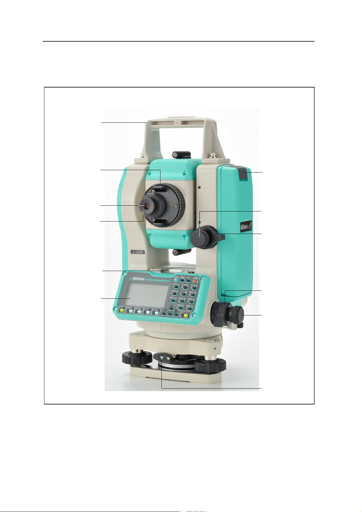
Parts of the Instrument
Te le sc o p e
Te le s c op e
Diopter ring
Plate level
Display
Tribrach
clamp knob
Battery mounting
button
Vertical tangent
Verti cal clamp
Upper plate
Upper plate clamp
screw
tangent screw
focusing ring
eyepiece
and face-1
keyboard
Carrying handle
Figure 1.1 and Figure 1.2 show the main parts of the DTM-322.
Introduction 1
Figure 1.1 Electronic Total Station DTM-322 – Face-1
Total Station DTM-322 Instruction Manual 3

1 Introduction
Optical sight
Horizontal axis
indication mark
Optical plummet
Data output/
Input connector
Leveling screw
Objective
(finder)
Circular level
Tribrach
Figure 1.2 Electronic Total Station DTM-322 – Face-2
4 Total Station DTM-322 Instruction Manual

Maintenance
Before using the instrument, read and follow the following maintenance instructions:
• Do not leave the instrument in direct sunlight or in a closed vehicle for
• If the DTM-322 instrument has been used in wet conditions, immediately wipe
• Sudden changes in temperature may cloud the lenses and drastically reduce the
• Do not store the DTM-322 instrument in hot or humid locations. In particular,
Introduction 1
prolonged periods. Overheating the instrument may reduce its efficiency.
off any moisture and dry the instrument completely before returning the
instrument to the carrying case. The instrument contains sensitive electronic
assemblies which have been well protected against dust and moisture.
However, if dust or moisture gets into the instrument, severe damage could
result.
measurable distance, or cause an electrical system failure. If there has been a
sudden change in temperature, leave the instrument in a closed carrying case in
a warm location until the temperature of the instrument returns to room
temperature.
you must store the battery in a dry location at a temperature of less than 30 °C
(86 °F). High temperature or excessive humidity can cause mold to grow on the
lenses. It can also cause the electronic assemblies to deteriorate, and so lead to
instrument failure.
• Store the battery with the battery discharged.
• When storing the instrument in areas subject to extremely low temperatures,
leave the carrying case open.
• Do not overtighten any of the clamp screws.
• When adjusting the vertical tangent screws, upper plate tangent screws, or
leveling screws, stay as close as possible to the center of each screw’s range.
The center is indicated by a line on the screw. For final adjustment of tangent
screws, rotate the screw clockwise.
• If the leveling base will not be used for an extended period, lock down the
leveling base clamp knob and tighten its safety screw.
• Do not use organic solvents (such as ether or paint thinner) to clean the
non-metallic parts of the instrument (such as the keyboard) or the painted or
printed surfaces. Doing so could result in discoloration of the surface, or in
peeling of printed characters. Clean these parts only with a soft cloth or a
tissue, lightly moistened with water or a mild detergent.
• To clean the optical lenses, lightly wipe them with a soft cloth or a lens tissue
that is moistened with alcohol.
Total Station DTM-322 Instruction Manual 5

1 Introduction
Reticle plate cover
• The reticle plate cover has been correctly
mounted. Do not release it or subject it to
excessive force to make it watertight.
• Before attaching the battery, check that the
contact surfaces on the battery and
instrument are clean. Press the battery into
place until the battery-mounting button rises
up to the battery top surface. If the battery is
not attached securely, the instrument is not
watertight.
• Press the cap that covers the data output/input connector terminal until it clicks
into place. The instrument is not watertight if the cap is not attached securely,
or when the data output/input connector is used.
• The carrying case is designed to be watertight, but you should not leave it
exposed to rain for an extended period. If exposure to rain is unavoidable,
make sure that the carrying case is placed with the Nikon nameplate facing
upward.
• When disposing of the battery, follow the laws or rules of your municipal waste
system.
• The instrument can be damaged by static electricity from the human body
discharged through the data output/input connector. Before handling the
instrument, touch any other conductive material once to remove static
electricity.
6 Total Station DTM-322 Instruction Manual

CHAPTER
2
Preparation 2
In this chapter:
Unpacking and Packing the Instrument
Charging the Battery
Detaching and Re-Attaching the Battery Case
Setting Up the Tripod
Centering
Leveling
Sighting
Setting Up the Prism Reflector
Face-1/Face-2 Measurements
Total Station DTM-322 Instruction Manual 7
2 Preparation
Unpacking and Packing the Instrument
Note – Handle the DTM-322 instrument gently to protect it from shocks and excessive
vibration.
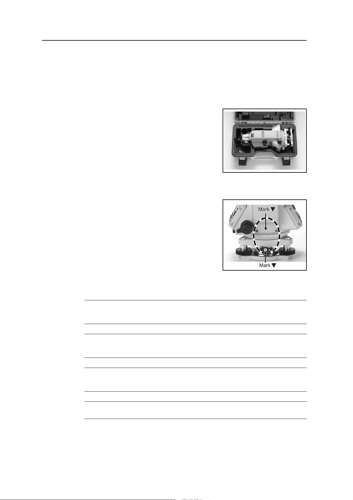
Unpacking
To unpack the instrument, grip the carrying handle
and gently remove the instrument from the carrying
case.
Packing
Note – Store the instrument with the battery case
attached.
To pack the instrument back into the carrying case:
1. Set the telescope in the horizontal face-1 position.
2. Align the storage mark on the bottom of
the face-1 keyboard with the mark on the
leveling base clamp knob.
3. Lightly fasten the clamp knobs.
4. Place the instrument in the carrying case.
Charging the Battery
Before charging the battery, read the warnings (also listed in the Safety section at the
front of this manual) and the following notes.
C
C
C
WARNING – To charge the battery, use only the battery charger that is supplied with the
instrument. Do NOT use any other charger or you may cause the battery to catch fire or
rupture.
WARNING – Do not cover the battery charger while the battery is being recharged. The
charger must be able to dissipate heat adequately. Coverings such as blankets or clothing can
cause the charger to overheat.
WARNING – Avoid recharging the battery in humid or dusty places, in direct sunlight, or near
heat sources. Do not recharge the battery when it is wet. If you do, you may receive electric
shocks or burns, or the battery may overheat or catch fire.
C
8 Total Station DTM-322 Instruction Manual
WARNING – You should take care not to short circuit the contacts. Short circuits can cause the
battery to catch fire or burn you.
Preparation 2
C
C
C
C
C
WARNING – Never burn or heat the battery. Doing so may cause the battery to leak or rupture.
A leaking or ruptured battery can cause serious injury.
WARNING – Before storing the battery or battery charger, cover the contact points with
insulation tape. If you do not cover the contact points, the battery or charger may short circuit,
causing fire, burns, or damage to the instrument.
WARNING – The battery is not itself waterproof. Do not get the battery wet when it is removed
from the instrument. If water seeps into the battery, it may cause a fire or burns.
WARNING – Use the battery specified in this manual. Using the other battery may lead to be
lower performance, it may cause a fire or burns.
CAUTION – Before charging the battery, read the instruction manual for the charger and the
battery.
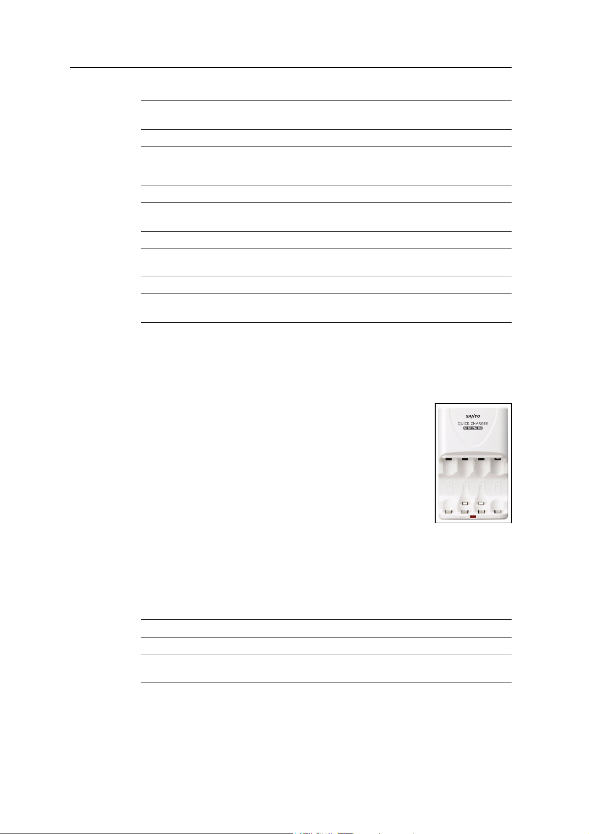
To Charge the battery
This charger is designed to charge 1 to 4 cells of AA Ni-MH rechargeable battery.
Before charging the battery, please read the attached instruction.
C
C
1. Place the battery cells into the compartments of the charger,
where the polarity (+/-) of the battery cell should be
connected with the same polarity indicated in the charger.
Do not plug the cell in reverse polarity.
When charging 1 to 2 AA cells at a time, insert them into
the end positions.
2. Plug the charger into an electrical outlet of 100-240 V AC
after placing the battery cells into the charger. The charger
indicator light is illuminated and battery charging begins.
Note – Do not insert or remove the battery cells during this charging process.
3. When charging is completed, the indicator light turns off. Remove the battery
cells from the charger.
If charging is still incomplete after 6 hours of charging, stop charging.
4. Disconnect the charger from the AC outlet.
WARNING – Do not insert the battery with the (+) and (-) ends reversed.
WARNING – Do not bring the (+) and (-) terminals into contact with metal objects. When
carrying or storing the batteries, avoid direct contact with metal objects.
Total Station DTM-322 Instruction Manual 9

2 Preparation
C
C
C
C
C
C
C
C
WARNING – Children should be supervised while handling the batteries.
WARNING – Do not use different types of batteries together.
WARNING – Do not peel off or damage the outer surface of the battery cell.
WARNING – If leaked liquid gets on the skin or clothing, wash off with clean water immediately.
WARNING – Do not connect 10 or more batteries in series.
WARNING – If something appears wrong with the charger and/or batteries, disconnect the
charger from the AC outlet immediately and contact your dealer.
WARNING – Disconnect the charger from the AC outlet promptly once charging is complete.
WARNING – Be sure to charge the batteries where the ambient temperature is between 0 °C
and 35 °C (32 °F and 95 °F).
C
WARNING – Be sure to use the charger with correct power source of 100-240 V AC.
Specified battery
SANYO Electric Co, Ltd. Nickel-Metal Hydride Battery HR-3UTG
Notes
• Charge the battery indoors where the ambient temperature is between 0 °C and
35 °C (between 32 °F and 95 °F). Outside of the indicated range, the battery’s
performance may deteriorate and the battery’s life may become short. If you try
to charge the battery when the ambient temperature is outside this range, the
protective circuit will activate and prevent it from being charged normally.
• To prevent malfunction, keep the charging plug clean.
• The battery may discharge while it is stored in the instrument or charger. Don’t
store the battery in the instrument or charger for a long time (more than 1
month). When the instrument is not used for a long time, the battery should be
taken out of the battery case to prevent leakage or rusting. If leaked liquid gets
on the skin or clothing, wash off with clean water immediately.
• During the charge, the battery and charger will become warm. This is normal.
10 Total Station DTM-322 Instruction Manual
• After charging the battery, do not recharge it until it has been fully discharged.
3
4
2
1
Recharging a fully charged battery lowers its performance.
• If the battery is used in low temperature (below 0 °C or 32 °F), the capacity is
reduced and provides shorter operation time than when used at room
temperature.
• If a battery is not used for a long period, it can never be charged to its full
capacity again.
• Battery pack BC-65 is not compatible with this instrument.
Detaching and Re-Attaching the Battery Case
Detaching the battery case
Preparation 2
C
CAUTION – Avoid touching the contacts on the battery case.
1. If the instrument is turned on, press [PWR] to turn it off.
2. Depress the battery mounting button while holding the battery case.
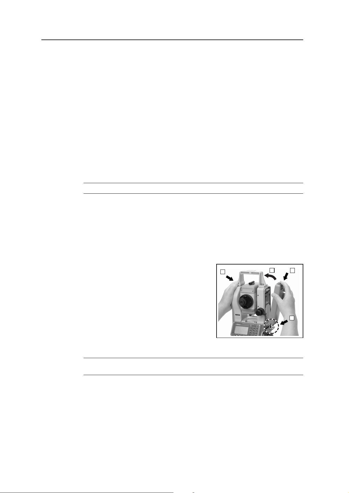
Attaching the battery case
Before you attach the battery case, clear any dust or other foreign particles from the
battery contacts.
1. Hold the instrument steady with one hand.
2. Fit the two projections at the bottom of the
battery case into the concave sections at the
bottom of the instrument.
3. Press the battery mounting button.
4. Push the battery case against the instrument
and release the battery mounting button.
Make sure that the battery mounting button
is fully released and the battery is securely
attached to the instrument.
C
CAUTION – If the battery case is not attached securely, this could adversely affect the
watertightness of the instrument.
Total Station DTM-322 Instruction Manual 11

2 Preparation
Setting Up the Tripod
C
CAUTION – The tops of the tripod ferrules are very sharp. When handling or carrying the
tripod, take care to avoid injuring yourself on the ferrules.
1. Open the tripod legs enough to for the instrument to be stable.
2. Locate the tripod directly over the station point. To check the tripod’s position,
look through the center hole in the tripod head.
3. Firmly press the tripod ferrules into the ground.
4. Level the top surface of the tripod head.
Note – If you want to use the plumb bob to center the instrument (see Centering,
page 13), you must level the tripod head precisely.
5. Securely fasten the thumb screws on the tripod legs.
6. Place the instrument on the tripod head.
7. Insert the tripod mounting screw into the center hole of the base plate of the
instrument.
8. Tighten the tripod mounting screw.
Note – Do not carry the instrument while it is attached to a tripod.
12 Total Station DTM-322 Instruction Manual

Centering
When you center the instrument, you align its central axis precisely over the station
point. To center the instrument, you can either use the optical plummet or a plumb
bob.
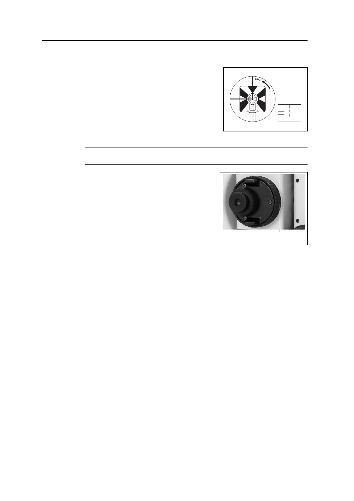
Centering using the optical plummet
Note – If you require high accuracy, check and adjust the optical plummet before you
center the instrument. For detailed instructions, see Checking and Adjusting the
Optical Plummet, page 133.
To center the instrument using the optical plummet:
1. Set up the instrument on the tripod. For detailed instructions, see Setting Up the
Tripod, page 12.
2. While looking through the optical plummet, align
the reticle with the station point. To do this, turn the
leveling screws until the center mark of the
reticle is directly over the image of the station point.
Preparation 2
3. While supporting the tripod head with one hand,
loosen the tripod leg clamps and adjust the lengths
of the legs until the air bubble is in the center of the
circular level.
4. Tighten the tripod leg clamps.
5. Use the plate level to level the instrument. For detailed instructions, see
Leveling, page 14.
6. Look through the optical plummet to check that the image of the station point is
still in the center of the reticle mark.
7. If the station point is off center, do one of the following:
– If the station point is slightly off center, loosen the tripod mounting screw
and then center the instrument on the tripod. Use only direct movement to
center the instrument. Do not rotate it.
When the instrument is centered, tighten the mounting screw.
– If the displacement of the station point is major, repeat this procedure
from Step 2.
Total Station DTM-322 Instruction Manual 13
2 Preparation
CB
A
1
CB
A
2
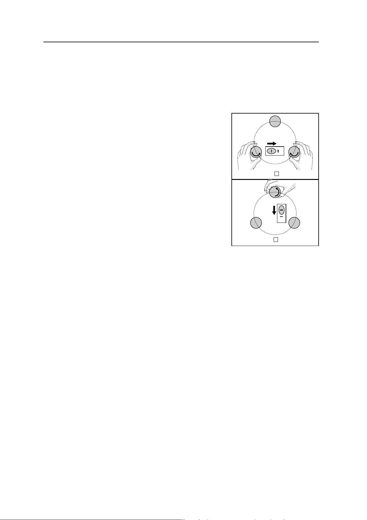
Leveling
When you level the instrument, you make the vertical axis of the instrument exactly
vertical. To level the instrument, use the plate level.
To level the instrument:
1. Loosen the upper plate clamp.
2. Rotate the alidade until the plate level is
parallel with any two of the leveling screws
(B and C).
3. Use leveling screws B and C to move the
bubble into the center of the level.
4. Rotate the alidade approximately 90°.
5. Use leveling screw A to move the bubble into
the center of the level.
6. Repeat Step 1 through Step 5 to center the
bubble in both positions.
7. Rotate the alidade 180°.
8. If the bubble in the plate level remains
centered, the instrument is level. If the
bubble moves off center, adjust the plate
level. For detailed instructions, see Checking and Adjusting the Plate Level,
page 132.
14 Total Station DTM-322 Instruction Manual
Sighting
Center
crosshairs
Diopter ring
Telescope focusing
ring
Preparation 2
When you sight the instrument, you aim the
telescope at the target, bring the target image into
focus, and align the image with the center
crosshairs of the reticle.
To sight the instrument:
1. Adjust the diopter:
a. Aim the telescope at a blank area, such
as the sky or a piece of paper.
C
WARNING – Never look at the sun through the telescope. If you do, you may damage or lose
your eyesight.
b. Looking through the eyepiece, rotate
the diopter ring until the reticle
crosshairs are in sharp focus.
2. Eliminate parallax:
a. Aim the telescope at the target image.
b. Rotate the focusing ring until the target
image is in sharp focus on the reticle
crosshairs.
c. Move your eye vertically and laterally
to check whether the target image moves relative to the reticle crosshairs.
If the target image does not move, there is no parallax.
d. If the target image does move, rotate the telescope focusing ring. Then
repeat from Step c.
3. Rotate the tangent screw:
– The final turn of the tangent screw should be in a clockwise directions, to
align the target accurately on the center crosshairs.
Total Station DTM-322 Instruction Manual 15
2 Preparation
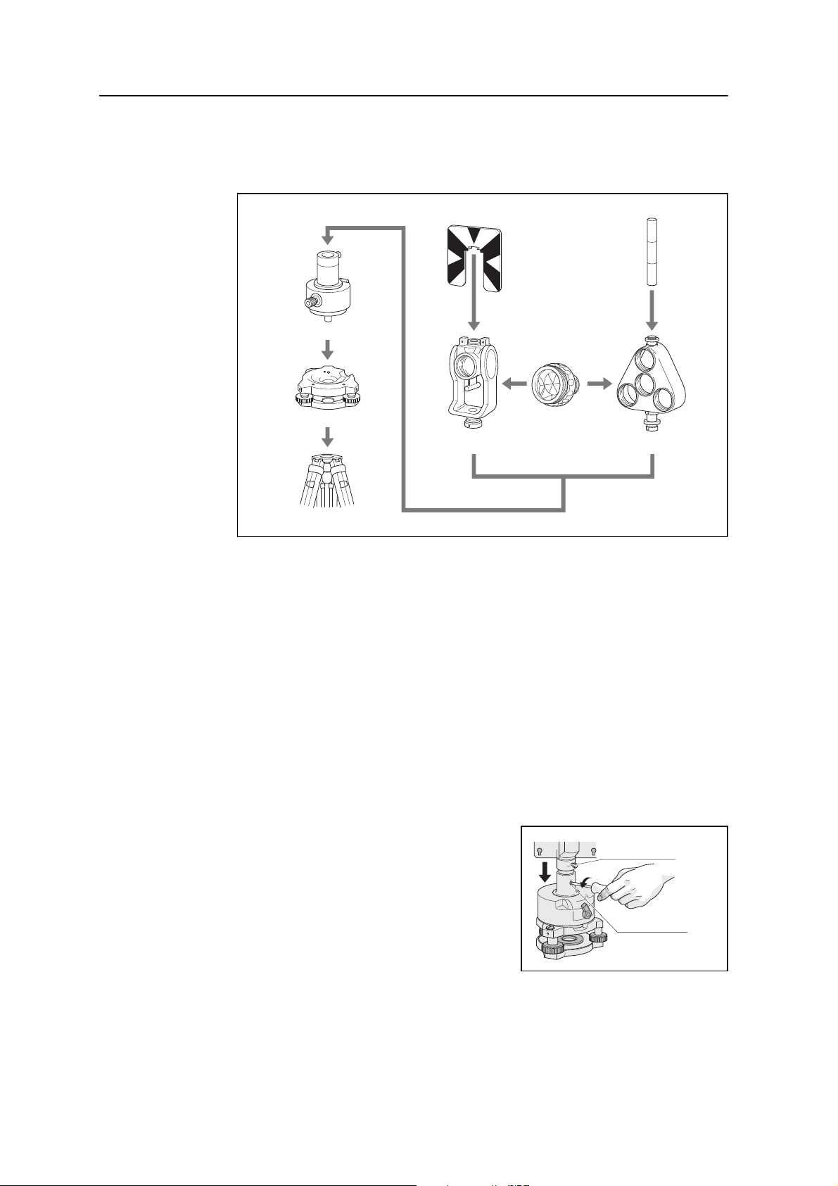
Tribrach adapter 13/14
Tribrach
Tripod
Target plate for single prism
Tiltable single
prism holder
Prism C
Ta r g e t po l e
Triple prism holder
Prism holder mount
Height adjustment
screw
Setting Up the Prism Reflector
1. Assemble the prism reflector as shown below.
2. Adjust the height of the tribrach adaptor (see page 16).
3. If necessary, change the direction of the prism (see page 17).
4. Set the prism constant (see page 17).
5. If you are using a single prism holder, set the position of the target plate (see
page 17).
Detailed instructions for Step 2 through Step 5 are provided on the following pages.
Adjusting the height of the tribrach adapter
The tribrach adapter has two height settings. To use the prism reflector with a DTM322 instrument, use the lower height setting.
To adjust the height of the tribrach adapter:
1. Remove the height adjustment screw from
the tribrach adapter.
2. Slide the tribrach adapter up or down the
prism holder mount until the height
adjustment screw holes on the prism holder
mount and on the tribrach adapter are
aligned.
3. Replace and tighten the adjustment screw.
16 Total Station DTM-322 Instruction Manual
 Loading...