

Page 1

TL - A320
GB
E
LINE ARRAY LIFT
INSTRUCTION MANUAL
Quick Operation Guide
ELEVADOR LINE ARRAY
MANUAL DE INSTRUCCIONES
Page 2

VMB ESPAÑOLA, S.A.
v8.06 - Depósito legal y Copyright 2008. Todos los derechos reservados.
Page 3

TORRE ELEVADORA
TOWERLIFT
TRAVERSENLIFT
PIED ÉLÉVATEUR
TL-A320
Fabricante - Manufacturer - Hersteller - Fabricant
VMB Española S.A.
Calle 2 - Pol. Ind. Picassent
E-46220 Picassent (VALENCIA) SPAIN
www.vmb.es - e-mail: contact@vmb.es
Este manual de usuario y catálogo anexo de piezas de repuesto es propiedad de VMB Española, S.A. Queda
prohibida su reproduccion total o parcial por cualquier medio que la tecnología actual permita.
Depósito legal y Copyright 2008. Todos los derechos reservados.
Page 4

E
X
RTS
W
N
TL-A320
1
N
2
P1
F
S
R
ALS
C
J
ILS
BU
BA
H
D
VMB ESPAÑOLA, S.A.
V
B
P
T
Q
v8.06 - Depósito legal y Copyright 2008. Todos los derechos reservados.
Page 5

Quick Operation Guide
ENGLISH
CONTENTS
1. Introduction.
2. Technical Data.
3. Security.
4. Instructions.
5. Maintenance.
6. Warranty.
7. Certifications.
1. INTRODUCTION
Thank you for choosing VMB Towerlifts.
You have acquired a first class, quality product
used by professionals around the world.
To be able to work with this tower, lifting and
flying PA and Line Array, please pay special
attention to this manual. Please observe the
technical data and follow all instructions fully
for a correct and safe use.
This manual should also be made available and
remain with the towerlift.
During the life of this towerlift, it may need spare
parts for maintenance. In this case please
contact your distributor.
Only original spare parts must be used. The
user loses all rights to warranty if any spare
parts other than originals are used or carries
out any modification or alteration to the towerlift.
For any questions relating to this towerlift
please indicate serial number and year of
production.
2. TECHNICAL IINFORMATION
2.1 – Towerlift mod. TL-A320
2.2 – Especially designed for lifting and flying
Line array directly from the floor to a height of
6m. Able to hang at 50cm from the main body
of the lift.
2.3 – Maximum load : 320 Kg. at 50 cm from
lift body..
All VMB towerlifts undergo a strict quality control to guarantee the maximum safety and
durability.
The TL-A320, has been especially designed
and engineered to hang Line Array to a
maximum height of 6m and a load of 320kg.
This lift is capable of situating the PA 50cm
from the body of the lift.
The benefit of placing the load at a distance
enables the user to achieve the perfect curve
and coverage for the Line array flown.
The TL-A320, incorporates the ALS system
(Auto-Lock-Security), ILS system (Inertia-
Lock-Security) and RTS system (Retentor-
System) all exclusive to VMB and which
guarantee the load will not fall and provide complete security.
ATTENTION: Do not use this towerlift if you
have not read and understood the instructions.
2.4 – Minimum Load : Can lift or lower without
load.
2.5 – Maximum Height : 6 m.
2.6 – Folded Height : 1,98 m.
2.7 – Base Surface : Diagonal 2,78 x 2,78 m.
2.8 – Transport Weight : 182 Kg.
2.9 – Construction Material : 6082-T6
aluminium for the main body comprised of 4
profiles and lifting carriage. DIN 2394 steel for
the base and outriggers. ST-37 steel for the
ALS security system and pulleys.
2.10 – Security Systems: ALS (Auto-Lock-
Security), ILS (Inertia-Lock-Security) which
guarantee complete security at all times. RTS
(Retentor-System) which guarantees the
profiles lift in order.
VMB ESPAÑOLA, S.A.
v8.06 - Depósito legal y Copyright 2008. Todos los derechos reservados.
Page 6

Quick Operation Guide
ENGLISH
2.11 – 1200kg Manual winch with automatic
disc brake.
2.12 - Cable : DIN 3060 steel. 180 Kg/mm
quality antitorsion. 6 mm diametre.
2.13 – Adjustable stabilisers on the outriggers
with anti-slip injected rubber base.
2.14 – Outriggers fixed with security locks.
3. SAFETY PRECAUTIONS.
3.1 – The TL-A320 is designed for lifing
Line Array and should never be used for
elevating persons.
2.15 – Spirit level to adjust vertical positioning.
2.16 – All lift elements are finished in polyester
2
satin black.
2.17 – 360º Wheels for ease of transport to
work place.
!
3.2 - Only situate the lift on hard, flat
surfaces checking that it is in a vertical
position with the spirit level (F) included. If
necessary, adjust with support stabilisers
(Q) by turning the handle (H). Do not use
any other materials to balance the lift.
3.3 – Check all outriggers are inserted
correctly and locked with security locks.
VMB ESPAÑOLA, S.A.
v8.06 - Depósito legal y Copyright 2008. Todos los derechos reservados.
Page 7

Quick Operation Guide
Kgs
3.4 – Never elevate the Line Array before
checking it is correctly attached to the lift.
3.5 – Never exceed the maximum weight
indicated on the towerlift and in this manual.
ENGLISH
3.6 – If there is excessive wind, place the
lift on firm ground and attach slings to add
stability. Never attach a sling to a vehicle
or any other element than can move.
3.7 – Do not use a ladder on the lift.
3.8 – Be carfeful of any high, obstructions
such as balconies, signs etc. It is important
to avoid the presence of cables beneath
the working position of the lift.
VMB ESPAÑOLA, S.A.
v8.06 - Depósito legal y Copyright 2008. Todos los derechos reservados.
Page 8

Quick Operation Guide
3.9 – Never stand below the raised mate-
rial and do not allow others to stand
beneath or around the working area of the
lift.
3.10 – Never try to move the lift once the
load is raised.
ENGLISH
3.11 – Never use the lift on a mobile surface
or on any vehicle.
3.12 – Before using the lift check the
condition of the cable. The cable should
not be broken or torn. NEVER use defect
cables and if in doubt change the cable.
Only use DIN 3060 steel cable 180 Kg/mm
quality torsion resistant cable.
3.13 – Never remove the handle from the
winch if the lift is elevated with load.
2
VMB ESPAÑOLA, S.A.
v8.06 - Depósito legal y Copyright 2008. Todos los derechos reservados.
Page 9

Quick Operation Guide
-25
3.14 – The minimum load for the brake
functioning in the winch is 25kg. Without
this weight the brake will not function.
3.15 – Do not grease or lubricate the break
mechanism in the winch. The break discs
have been especially greased with a
special anti heat, pressure material.
Other products must not be used so as to
avoid the break not working effectively.
ENGLISH
ORIGINAL
3.16 – All profiles must be lowered before
the lift is transported.
3.17 – Only original spares must be used.
VMB ESPAÑOLA, S.A.
v8.06 - Depósito legal y Copyright 2008. Todos los derechos reservados.
Page 10

Quick Operation Guide
ENGLISH
4. INSTRUCTIONS.
4.1 - Situate the lift on its transport wheels (T)
upon a flat and stable surface.
When erecting the lift in open air, the risk of
wind is prevalent.
Where wind speeds exceed 30 Km/h it is
essential to tie the lift. 2 lateral fixing points (X)
are situated at the top of profile 2, where
tensors should be attached and fixed on secure
and firm ground (NEVER ON A VEHICULE OR
ANYTHING THAT CAN MOVE).
4.2 – Remove the outriggers from their
transport compartments (S) and place them in
the working position (V) ensuring they are fixed
with the security locks (R). The long outriggers
are placed and the front beneath the load. The
short outriggers are placed at the back.
4.3 – Remove the front support bars (BA) from
their transport compartment (S) and place them
in their corresponding fixed position (D) on each
front outrigger and at the top of the first profile
(E) ensuring they are fixed with the pins
provided BU/P1.
To correctly fix the front support bars (BA),
adjust the support of the front outrigger by
turning the stabiliser handel in the necessary
direction.
Insert clips (BU) and security pins (P1).
Adjust the vertical position of the lift with the
stabilisers (Q) turning the handels so that the
spirit level is centred (F).
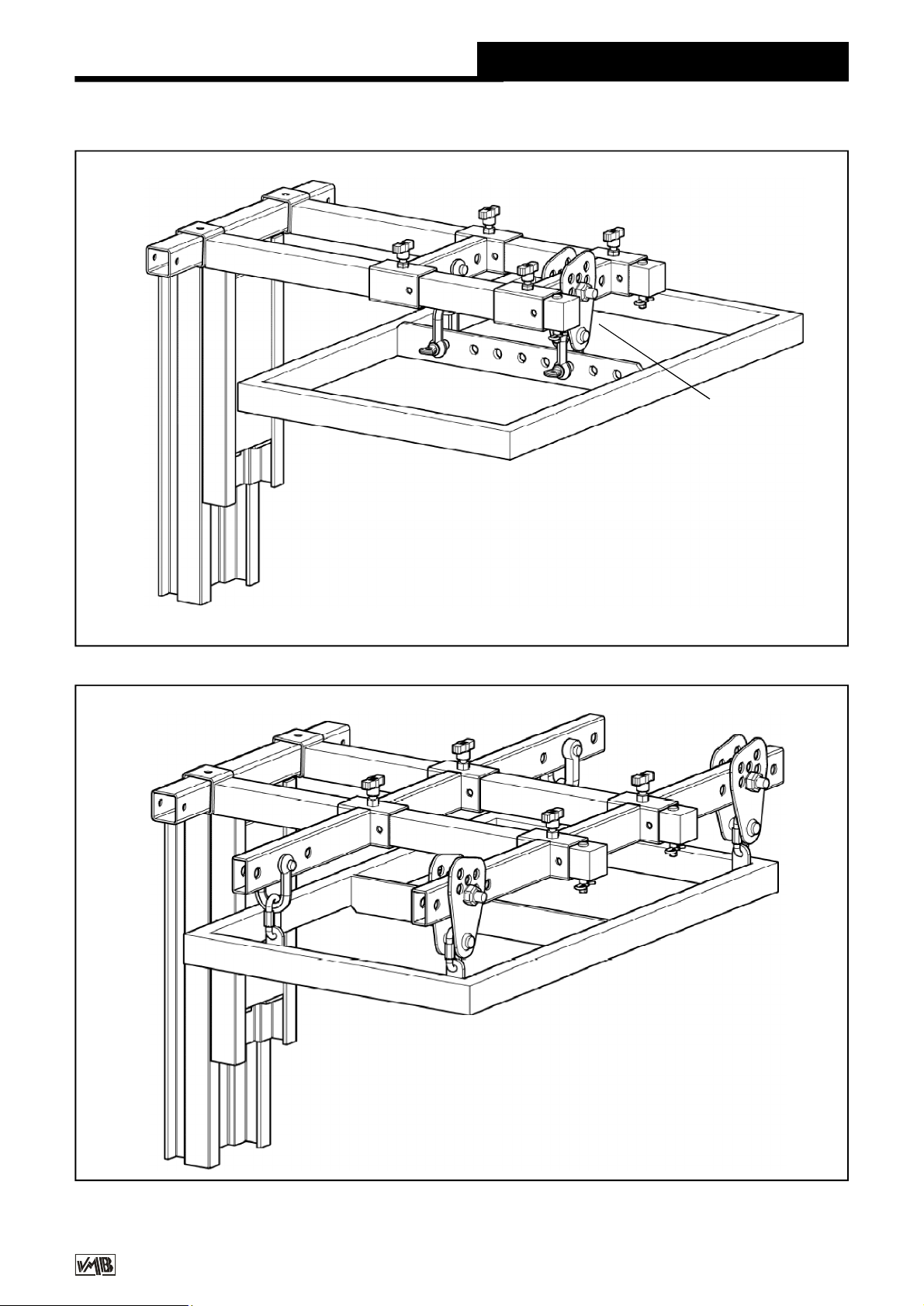
Support FAS-01 is to be fixed to the forks by
either 1 or 2 points. See fig. 1.
If the Line Array Buffer has 4 link points use
the FAS-02 support which enables the Line
Array to be flown from 4 points, see fig. 2.
Both supports FAS-01 and FAS-02 are inserted
on the forks as follows:
The Line Array cabinets will be attached to their
buffer with the angles calculated according to
the acoustic coverage required.
This ensures the Line Array cabinets can be
curved in function with the necessary degrees
required between them.
The system should be attached at the
necessary distance to achieve the required
curve. The last cabinet should not hit the body
of the lift. See fig. 3.
To ensure the maximum security margin it is
necessarry to always attach the Line Array at
the minimum distance possible from the body
of the lift. This will mean that the bottom cabinet
is as close as possible to the body of the lift.
See fig. 3A.
To avoid overloading do not seperate
uneccessarily the Line Array from the body of
the lift. See fig. 3B.
4.4 – Let go of transport security B, remove
the forks and place them horizontally.
Place the lifting carriage at the required height
so that the Line Array buffer can be attached.
The careful positioning of the front outriggers
enables the Line Array to fit between them and
ease assembley on to the forks.
VMB ESPAÑOLA, S.A.
v8.06 - Depósito legal y Copyright 2008. Todos los derechos reservados.
Page 11
Quick Operation Guide
ENGLISH
FAS-01
PR-01
FAS-02
Fig. 1
PR-01
VMB ESPAÑOLA, S.A.
Fig. 2
v8.06 - Depósito legal y Copyright 2008. Todos los derechos reservados.
Page 12

Quick Operation Guide
ENGLISH
BA
TL-A320TL-A320
MR-SPI
FAS-01
Fig. 3
BC-075L
PR-01
PAS-SPI
PAT-01
MO-30
MR-PAS
GS-500
FAS-02
VMB ESPAÑOLA, S.A.
v8.06 - Depósito legal y Copyright 2008. Todos los derechos reservados.
Page 13

Quick Operation Guide
4.5 - The maximum load of the TL-A320 is
320 Kg with the load point at 50 cm from the
lift’s body.
The loading point capacity can be found on the
vertical line which marks the centre of gravity
of the Line Array wich is to be flow.
The situation of the centre of gravity depends
upon the chosen Line Array and is necessary
to calculate before use. Never the less, it is
usually situated at the centre of the Line Array.
ENGLISH
LOAD SPECIFICATIONS
65 cm
60 cm
55 cm
50 cm
See example Fig. 4; 6 Lynx LX-V8 cabinets
with a total of 309 Kg.
Never overload the lift above the stated
maximum weight of 320 Kg. See Fig. 5.
50 cm
TL-A320
Centred load
DISTANCE
to the lifting carriage
B 30 cm 300 kg
C 40 cm 253 kg
D 50 cm 219 kg
E 60 cm 193 kg
F 70 cm 174 kg
Maximum lifting
LOAD
Fig. 5
VMB ESPAÑOLA, S.A.
LYNX (309 Kg)
TL-A320
Fig. 4
ABCDEF
TL-075C
Fig. 6
v8.06 - Depósito legal y Copyright 2008. Todos los derechos reservados.
Page 14

Quick Operation Guide
4.6 - The TL-A320, can also be used as a
conventional towerlift.
If you are using it as a conventional towerlift
always place the load as close to the body as
possible. In all frontal load towerlifts the
maximum load is reduced the further away from
the body the load is placed.
See load table opposite indicating distance of
centred load for a TL-075C towerlift. (Fig. 6)
4.7 – Elevating the lift:
Once the Line Array is attached to its buffer
and in the desired position on the forks it is
ready to be lifted to the required height. Turn
the winch handle in a clockwise direction to
elevate the lift.
During elevation the RTS system (Retentor-
System) will ensure that the profiles lift one by
one.
First, the lifting carriage with the attached Line
Array will raise. When it has reached the top
then the first profile will start to rise. When this
has reached the top the second profile will raise
followed by the third.
The ILS and ALS enable the lift to rise and
automatically block the carriage and profiles
whilst rises ensuring that it will never fall. The
lift, with the Line array attached will remain fixed
at all times.
Once the system is elevated to its required
height gently turn the handle in a clockwise
direction. The security systems will ensure that
the load stays fixed and blocked. The red ALS
locks will be blocked. This enables the cable
to be without any force and means it is only
used for the elevation and descent of the lift.
The following instructions will help you to
bring the system down.
4.8 – Descending the lift:
To bring the lift down you need to first turn the
winch handle slightly clockwise and at the same
time push the red ALS lock in (G). (Fig. 7)
This releases the blocking systems. Then turn
the handle anti clockwise, whilst maintaining
the ALS lock pushed in until the profile has been
completely lowered.
ENGLISH
G
Fig. 7
All red ALS locks should be held in one by one
whilst the handle is turned anti clockwise and
the profiles are brought down, one by one. If
you release your finger from the ALS lock it
will automatically block. In this case, repeat the
first operation by turning slightly clockwise and
then anti clockwise whilst always pushing the
red ALS lock in.
It is necessary to completely lower each profile
before starting to lower the next. If you push
another red ALS lock without having completely
lowered the previous profile the first profile will
remain blocked by the security system and you
will not be able to lower it later.
If this happens, elevate the towerlift to the
locked position and free the lock so that you
can commence the descent again until it is
completely lowered.
Finally, release the carriage lock following the
same principle as before and lower it to the
required level to be able to dismount the Line
Array from the lift.
4.9 - Transport
Once all the profiles are completely lowered
remove the FAS-01 or FAS-02 support and the
forks placing them in their horizontal position
facing down. Lower the carriage so that right
fork can be fixed and blocked for transport (B).
Remove the front support bars ( BA ) by taking
out the pins (BU). Replace the pins in the top
support ( E ) of the lift’s base profile and also
at the top of each front support bar.
VMB ESPAÑOLA, S.A.
v8.06 - Depósito legal y Copyright 2008. Todos los derechos reservados.
Page 15

Quick Operation Guide
ENGLISH
Place the bars in their transport compartment.
Remove the outriggers, releasing the locks and
place in their transport position (S). Turn and
tighten the fixing screws (J). The lift can be
transported horizontally by adding the RH-4 kit.
5. MAINTENANCE.
5.1 - Periodically check the condition of the
cable. If a cable is torn or broken it should be
replaced immediately. Do not use the lift if the
cable is not perfect. Only use torsion resistant
steel cable DIN 3060.
5.2 - The lift is supplied completely greased
from the factory. Never the less, we
recommend you periodically grease (depending
on amount used) the teeth of the winch (CD),
end point of the handle (RM), bar (EB) (Fig. 8)
and the profile nylon drums.
5.3 - All lifts should undergo an annual
technical inspection carried out by an
authorized VMB dealer to check the
certifications and general condition of all the
lift’s elements and security systems involved
in the lift’s use.
5.4 – Only use original spare parts to guarantee
a continued security level.
The user loses all rights to warranty if any spare
parts other than originals are used or carries
out any modification or alteration to the towerlift.
5.5 – To request a spare part please indicate
the corresponding code which can be found in
this manual.
VMB Tecnical Assistance
S.A.T. in Spain
Tel : +34 902 34 10 34
Fax: +34 961 22 11 77
EB
EB
RM
CD
Figura 8
ATTENTION: Do not grease or lubricate the
break mechanism.
The brake discs have been greased with a
special heat and pressure resistant grease. Do
not use other products.
6. GUARANTEE.
The warranty period for this lift is 3 years from
the date of purchase.
VMB Española, S. A. promises, that from from
the date of purchase and during the warranty
period to resolve any faults that may occur
produced through defect material or fabrication.
Damage caused by inproper use, product
modification, terciary manipulation or accidental fire are not covered by this warranty.
7. CERTIFICATIONS
-
EC Machinery Directive
89/392/ECC and 98/37/ECC
- BGV C1 (GUV-VC1) / BGG 912 (GUV-G912)
VMB ESPAÑOLA, S.A.
v8.06 - Depósito legal y Copyright 2008. Todos los derechos reservados.
Page 16

Manual de instrucciones
CONTENIDO
ESPAÑOL
1. Introducción
2. Datos técnicos
3. Normas de seguridad
4. Instrucciones de uso
5. Mantenimiento
6. Garantía
7. Certificaciones
1. INTRODUCCION
Estimado usuario:
Agradecemos su confianza al adquirir las
torres elevadoras VMB.
Tiene en sus manos un producto de calidad
y fiabilidad contrastadas por la dilatada
experiencia de los usuarios profesionales
en todo el mundo.
Para poder trabajar con este elevador
volando todo tipo de equipos de sonido sin
peligro y de forma segura, lea atentamente este
manual, observe los datos técnicos y siga
íntegramente todas las instrucciones de
utilización y seguridad.
Este manual de instrucciones, deberá estar
disponible permanentemente junto al elevador.
Todos los elevadores VMB son sometidos a
un constante control de calidad y durísimas
pruebas de verificación, para garantizar la
máxima fiabilidad y resistencia.
El elevador, TL-A320, incorpora los sistemas
de seguridad ALS (Automatic-Lock-Security),
ILS (Inertia-Lock-Securyty) y RTS (RetentorSystem) exclusivos de VMB, que garantizan
la imposibilidad de caida de la carga y una
total seguridad de utilización.
ATENCION:
No utilice este elevador sin haber leído y
seguir estas instrucciones. En caso contrario,
podría llegar a provocar un grave accidente.
Durante la vida útil del elevador, puede
necesitar piezas de repuesto. Diríjase en este
caso a su distribuidor habitual.
Solamente deben utilizarse piezas de repuesto
originales. El usuario perderá todos sus
derechos de garantía si incorpora cualquier
repuesto que no sea original o realiza
cualquier modificación en el elevador.
Para cualquier consulta sobre el elevador,
deberá indicar el número de serie y año de
construcción.
2. DATOS TECNICOS
2.1 - Torre elevadora modelo TL-A320.
2.2 - Diseñada especialmente para levantar
equipos de sonido tipo line array desde el
mismo suelo en sentido vertical a cualquier
altura hasta 6 m., con un avance respecto al
cuerpo de la torre de 50 cm.
El elevador TL-A320, ha sido proyectado
especialmente para levantar hasta 6 metros
de altura, equipos de sonido tipo line array
con un peso de 320 Kg desplazados 50 cm.
en avance respecto al cuerpo de la torre.
Este desplazamiento, es necesario para
poder angular los recintos acústicos los
grados precisos para lograr una perfecta
cobertura de sonorización.
VMB ESPAÑOLA, S.A.
2.3 - Carga máxima elevable: 320 Kg. desplazada 50 cm del cuerpo del elevador.
2.4 - Carga mínima elevable: Puede subir o
bajar sin carga alguna.
2.5 - Altura máxima: 6 m.
2.6 - Altura plegada: 1,98 m. Altura mínima de
carga : 0,05 m.
2.7 - Superficie de la base : Diagonales 2,78
x 2,78 m.
v8.06 - Depósito legal y Copyright 2008. Todos los derechos reservados.
Page 17

Manual de instrucciones
ESPAÑOL
2.8 - Peso de transporte : 182 Kg.
2.9 - Material de construcción: Cuerpo principal
de cuatro tramos más carro elevador, en perfil
de aluminio extrusionado 6082-T6. Base,
patas y soportes varios, en perfileria de acero
según DIN 2394. Gatillos de seguridad y
poleas acanaladas en acero ST-37.
2.10 - Sistemas de fijación, seguridad ALS
(Automatic-Lock-Security), ILS (Inertia-Lock-
Securyty) que fijan e imposibilitan la caida de
la carga en todo momento y RTS (RetentorSystem) exclusivo de VMB, que garantiza la
elevación ordenada de todos los tramos del
elevador fiabilizando al máximo su manipulación.
2.11 - Cabrestante de acción manual de
1.200Kg de capacidad de carga máxima con
freno de discos automático.
2.12 - Cable : Acero según DIN 3060. Calidad
180 Kg/mm2 antitorsión. Diámetro 6 mm.
2.13 - Platillos estabilizadores ajustables en las
patas, con apoyos antideslizantes de caucho
inyectado.
2.14 - Fijación de las patas con gatillos de
seguridad.
2.15 - Nivel de burbuja para ajustar la posición
vertical de la torre.
2.16 – Todos los elementos del elevador
están acabados en poliéster negro satinado.
2.17 - Ruedas direccionables para facilitar el
transporte de la torre en posición vertical y
plegada hasta su emplazamiento de trabajo.
3. NORMAS DE SEGURIDAD.
3.1 - El elevador TL-A320 es una máquina
diseñada para la elevación de cargas en
sentido vertical, NUNCA se debe utilizar
como plataforma elevadora de personas.
3.2 - Colocar el elevador sólo en superficies
duras y planas, verificando que está en
posición vertical, mediante el nivel de
burbuja (F) situado en el tramo base.
Ajustar si fuera necesario con los platillos
de apoyo (Q), girando la manivela (H) en
el sentido adecuado. Nunca utilice cuñas
ni elementos extraños para equilibrar el
elevador.
!
VMB ESPAÑOLA, S.A.
v8.06 - Depósito legal y Copyright 2008. Todos los derechos reservados.
Page 18

Manual de instrucciones
Kgs
3.3 - Comprobar que las patas están
correctamente montadas y sujetas por sus
pasadores retenedores de seguridad.
3.4 - Nunca se debe elevar una carga
sin antes verificar que está correctamente
apoyada y centrada en los soportes
elevadores adecuados, de forma que el
peso de la carga sólo actúe en sentido
vertical.
ESPAÑOL
3.5 - No se debe sobrepasar la capacidad
de carga máxima indicada en la etiqueta
de características del elevador y en este
manual de instrucciones.
3.6 - Si existe posibilidad de viento fuerte o
en ráfagas, coloque el elevador en suelo
firme y asegúrelo con la ayuda de tirantes.
Nunca fije un tirante sobre un vehículo
o cualquier otro elemento que pueda
desplazarse.
3.7 - No use escaleras encima del elevador
ni las apoye en él para realizar ningún tipo
de trabajo.
VMB ESPAÑOLA, S.A.
v8.06 - Depósito legal y Copyright 2008. Todos los derechos reservados.
Page 19

Manual de instrucciones
3.8 - Tenga cuidado con todo tipo de
salientes por encima del elevador como
cornisas, balcones, letreros luminosos,
etc...
Es muy importante evitar la presencia de
cables por debajo de la altura de trabajo del
elevador.
3.9 - Nunca se ponga debajo de la carga ni
permita la presencia de otras personas en
la zona de trabajo del elevador.
ESPAÑOL
3.10 - No desplace nunca el elevador si se
encuentra con la carga elevada. No es
aconsejable realizar ningún tipo de
movimiento, ni tan siquiera pequeños
ajustes de posicionamiento.
3.11 - No utilice nunca el elevador sobre
una superficie móvil o vehículo.
3.12 - Antes de utilizar el elevador, verifique
el estado del cable. El cable no debe
presentar rotura de hilos o aplastamiento.
NUNCA use cables defectuosos y en caso
de duda cambie el cable. Sólo utilice cable
de acero según DIN 3060. Calidad 180 Kg/
mm2 resistente a la torsión.
VMB ESPAÑOLA, S.A.
v8.06 - Depósito legal y Copyright 2008. Todos los derechos reservados.
Page 20

Manual de instrucciones
3.13 - Nunca desmonte la manivela del
cabrestante si el elevador está con carga y
elevado.
ESPAÑOL
-25
3.14 - La carga mínima para el funciona-
miento del freno del cabrestante sin problemas, es de 25Kg. Sin esta carga mínima el
freno podría no actuar.
3.15 - No engrase ni lubrique el mecanismo
de freno del cabrestante. Los discos de
freno, han sido engrasados con una grasa
especial resistente al calor y la presión.
No deben ser utilizados otros productos
para evitar influir negativamente en el
funcionamiento del freno.
3.16 - Para el transporte del elevador hay
que bajar todos los tramos.
ORIGINAL
VMB ESPAÑOLA, S.A.
3.17 - Solamente deben utilizarse piezas
de repuesto originales.
v8.06 - Depósito legal y Copyright 2008. Todos los derechos reservados.
Page 21

Manual de instrucciones
ESPAÑOL
4. INSTRUCCIONES DE USO.
4.1 - Coloque la torre elevadora apoyada en
sus ruedas de transporte (T) en su emplazamiento de trabajo sobre una superficie plana y
firme.
En el caso de montar el elevador al aire libre,
existe el riesgo que durante su utilización se
genere viento.
A partir de una velocidad del viento de 30 Km/h
es imprescindible arriostrar el elevador, para
lo cual se han previsto dos argollas laterales
de fijación (X) situadas en la parte superior del
segundo tramo, donde deberán fijarse los
tensores que serán anclados a lugares firmes
y seguros (nunca sobre un vehículo o cualquier
otro elemento que pueda desplazarse).
4.2 - Saque las patas de su soporte para
transporte (S) e insértelas a fondo en sus
alojamientos de trabajo (V) comprobando que
quedan sujetas por los gatillos retenedores
(R). Las patas largas delante, bajo la carga y
las cortas detrás .
4.3 - Saque los brazos de apoyo frontales ( BA)
del soporte de transporte (S) y colóquelos en
sus puntos de anclaje (D) sobre cada pata
delantera y (E) en los laterales de la parte
superior del tramo base, fijándolos con los
pasadores de seguridad (BU/P1).
Para poder colocar correctamente los brazos
de apoyo frontales (BA), deberá ajustar el apoyo de las patas delanteras, girando adecuadamente las manivelas de los apoyos
regulables de las patas.
Colocar los bulones (BU) y los pasadores de
seguridad (P1).
4.4 – Soltar el seguro de transporte B , sacar
los brazos de carga y volver a colocarlos en
posición horizontal.
Colocar el carro elevador a la altura necesaria
para poder fijar el soporte de volado del equipo
de line array.
La especial disposición de las patas delanteras, permite situar el equipo de sonido en el
suelo justo bajo los brazos de carga.
Sobre los brazos de carga, se colocarán
los soportes FAS-01, en el caso de volar un
equipo con fijación central por uno o dos
puntos de vuelo, fig. 1.
En el caso de que el soporte de volado del
equipo de sonido tenga cuatro anclajes
perimetrales, se utilizarán los soportes FAS-
02 que permiten suspender los soportes de
volado desde cuatro puntos, ver fig. 2.
Tanto los soportes FAS-01 como los FAS-02
se colocarán sobre los brazos de carga en la
posición y forma que se indica seguidamente:
Los recintos acústicos del equipo de sonido,
se montarán sobre su soporte de volado con
las angulaciones calculadas para la cobertura
acústica requerida.
Esto condiciona que los recintos de line array
se curvarán hacia detrás en función de los
grados necesarios entre ellos.
El equipo deberá colocarse en consecuencia
sobre los brazos de carga del elevador con el
avance necesario para conseguir que esta
curvatura pueda realizarse, sin que la parte
trasera inferior del último recinto tropiece con
el cuerpo del elevador. Ver fig. 3.
Para conseguir el máximo margen de seguridad, es necesario colocar siempre el equipo
de sonido sobre los brazos de carga del
elevador con el avance mínimo posible, de
forma que la parte trasera inferior del último
recinto del equipo line array se encuentre lo
más cerca posible del cuerpo de la torre. Ver
fig. 3A.
No separar innecesariamente el equipo de
sonido del cuerpo de la torre para evitar una
sobrecarga. Ver fig. 3B.
VMB ESPAÑOLA, S.A.
v8.06 - Depósito legal y Copyright 2008. Todos los derechos reservados.
Page 22

Manual de instrucciones
ESPAÑOL
FAS-01
PR-01
FAS-02
Figura 1
PR-01
VMB ESPAÑOLA, S.A.
Figura 2
v8.06 - Depósito legal y Copyright 2008. Todos los derechos reservados.
Page 23

Manual de instrucciones
ESPAÑOL
BA
TL-A320TL-A320
MR-SPI
FAS-01
Figura 3
BC-075L
PR-01
PAS-SPI
PAT-01
MO-30
MR-PAS
GS-500
FAS-02
VMB ESPAÑOLA, S.A.
v8.06 - Depósito legal y Copyright 2008. Todos los derechos reservados.
Page 24

Manual de instrucciones
4.5 - La carga máxima del elevador TL-A320
es de 320 Kg con el punto de aplicación
desplazado a 50 cm. del cuerpo del elevador.
El punto de aplicación de la carga se encuentra
en la línea vertical que pasa por el centro de
gravedad del conjunto del equipo de audio a
volar.
La situación del centro de gravedad dependerá
del equipo que se necesite volar y es necesario
determinarlo en cada caso. No obstante, es
habitual que esté situado sobre el centro del
conjunto del equipo. Ver ejemplo de volado de 6
recintos Line Array LYNX con un peso total de
309 Kg. Fig 4.
ESPAÑOL
ESPECIFICACIONES DE CARGA
65 cm
60 cm
55 cm
50 cm
TL-A320
Nunca debe sobrecargarse el elevador por encima de su carga máxima de trabajo de 320 Kg.
Ver no obstante la fig. 5 de cargas y distancias.
La seguridad de trabajo es lo más importante.
50 cm
LYNX (309 Kg)
Figura 5
Distancia del centro de
la carga a la torre
B 30 cm 300 kg
C 40 cm 253 kg
D 50 cm 219 kg
E 60 cm 193 kg
F 70 cm 174 kg
Carga máxima
elevable
ABCDEF
VMB ESPAÑOLA, S.A.
TL-A320
Figura 4
TL-075C
Figura 6
v8.06 - Depósito legal y Copyright 2008. Todos los derechos reservados.
Page 25

Manual de instrucciones
ESPAÑOL
4.6 - El elevador TL-A320, puede ser utilizado
igualmente como una torre elevadora tradicional.
Si se utiliza este elevador como torre de
elevación, coloque SIEMPRE la carga a
elevar lo más cerca posible del cuerpo de la
torre. En todas las torres elevadoras de carga
frontal, la capacidad máxima de carga
disminuye con la distancia de aplicación
respecto al cuerpo de la torre
Véase el cuadro de cargas en función de la
distancia del centro de aplicación de la carga
en una torre elevadora TL-075C. (Fig. 6)
4.7 - Operación de subida:
Una vez el equipo de sonido quede montado y
suspendido perfectamente posicionado sobre
los brazos de carga del elevador, solo es
necesario girar la manivela del cabrestante en
el sentido de las agujas de un reloj para que el
elevador comience a subir el equipo hasta su
correcto emplazamiento.
Durante la operación de subida, el sistema
RTS (Retentor - S ystem) del elevador,
garantiza que los diferentes tramos subirán
ordenadamente.
Primero subirá el carro portabrazos, junto con
el equipo de sonido, cuando el carro haya
subido completamente hasta la parte superior,
comenzará a subir el tramo primero, cuando
este haya subido completamente, comenzará
a subir el tramo 2 y así hasta la elevación total
máxima de 6 metros.
El elevador con el equipo de sonido volado,
quedará fijado a cualquier altura en el momento
que dejemos de girar la manivela del cabrestante, haciendo imposible su caída o descenso.
Una vez elevado el equipo de sonido hasta la
altura de volado requerida, girar la manivela
del cabrestante ligeramente en el sentido de
bajar. Los sistemas de fijación y seguridad
actuarán y todo el elevador quedará bloqueado
y asegurado. Los gatillos rojos, quedarán
igualmente bloqueados y no podrán ser
pulsados. El cable de acero quedará sin
efecto. Solamente se utiliza durante las
operaciones de subir o bajar.
Para poder bajar el elevador, será necesario
seguir las instrucciones que se detallan a
continuación.
4.8 - Operación de bajar:
Para poder bajar el elevador con el equipo de
sonido volado, girar ligeramente presionando
la manivela del cabrestante en el sentido de
subir y pulsar simultáneamente el gatillo rojo
(G) del tramo base o del último tramo que esté
bajado completamente. (Fig. 7)
Los sistemas de seguridad ILS y ALS del
carro portabrazos y de todos los tramos del
elevador, permiten su subida, pero bloquean
automáticamente el carro y los tramos del
elevador en todo momento impidiendo su
retroceso.
VMB ESPAÑOLA, S.A.
G
Figura 7
v8.06 - Depósito legal y Copyright 2008. Todos los derechos reservados.
Page 26

Manual de instrucciones
ESPAÑOL
Esta maniobra permitirá que el gatillo rojo de
seguridad pueda de nuevo pulsarse, liberando
el tramo de la torre, de forma que girando ahora
la manivela del cabrestante en el sentido de
bajar, el elevador bajará normalmente.
Todos los gatillos rojos podrán ser pulsados
conforme los tramos del elevador bajen.
Si una vez bajado completamente cualquiera
de los tramos, seguimos girando la manivela
del cabrestante en el sentido de bajar, sin
pulsar el gatillo rojo correspondiente para
liberar el tramo siguiente, el elevador se
bloqueará y bloqueará igualmente de nuevo
los gatillos rojos, impidiendo que puedan
pulsarse.
En este caso, repetir la operación descrita
inicialmente de subir la torre ligeramente para
liberar el gatillo bloqueado y continuar
bajando de la forma ya descrita.
Es necesario bajar completamente cada
tramo del elevador antes de iniciar la bajada
del tramo siguiente. Si se pulsara otro gatillo
para iniciara la bajada del tramo siguiente, sin
haber bajado completamente el tramo anterior,
el tramo primero quedaría bloqueado por el
sistema de seguridad y no podría bajarse
completamente luego.
4.9 - Transporte:
Pliegue la torre bajando completamente todos
los tramos. Una vez plegada, retire los soportes
FAS-01 o FAS-02 , saque los brazos de carga
y colóquelos de nuevo en posición vertical
hacia abajo. Baje el carro de forma que el
brazo de carga derecho pueda fijarse con el
pasador de bloqueo para transporte (B).
Desmonte los brazos de apoyo frontales (BA)
quitando los pasadores de seguridad y los
bulones (BU) de fijación.
Coloque de nuevo los bulones con sus
pasadores de seguridad en los soportes
superiores ( E ) del tramo base de la torre y
en el extremo superior de cada brazo de
apoyo frontal.
Coloque los brazos de apoyo en sus
alojamientos para transporte
Desmonte las patas liberando los gatillos de
retención y colóquelas en su posición de
transporte (S).
Apriete los pomos de fijación (J)
El elevador puede ser transportado en
posición vertical sobre sus ruedas de
transporte o en sentido horizontal, colocando
el kit de transporte RH-4.
Si esto ocurre, se deberá subir de nuevo el
último tramo, liberar el gatillo que permite
bajar el tramo que había quedado bloqueado
y bajarlo completamente, siguiendo, a continuación, el procedimiento de bajar hasta
tener bajados completamente todos los
tramos del elevador.
Liberar por último, el gatillo del carro
portabrazos y bajar el carro, dejándolo a la
altura necesaria para poder desmontar los
recintos acústicos.
VMB ESPAÑOLA, S.A.
5. MANTENIMIENTO.
5.1 - Compruebe periódicamente el estado del
cable. Si un cable presenta rotura de hilos o
aplastamiento, debe ser sustituido inmediatamente por otro nuevo. No utilice el elevador
con cables en mal estado. Utilice solamente
cable de acero DIN 3060 resistente a la torsión.
v8.06 - Depósito legal y Copyright 2008. Todos los derechos reservados.
Page 27

Manual de instrucciones
ESPAÑOL
5.2 - La torre elevadora se suministra
completamente engrasada de fábrica. No
obstante, se recomienda engrasar periódicamente (según el uso) la corona dentada del
cabrestante (CD), los cojinetes del árbol de
accionamiento y el buje (EB), la rosca de la
manivela (RM) (Fig. 8) y los rodillos de nylón
de los tramos.
EB
EB
RM
5.4 - Solamente deben utilizarse piezas de
repuesto originales para garantizar una
continuada seguridad de uso.
El usuario pierde todos los derechos de
garantía si incorpora otros repuestos que no
sean originales o lleva a cabo cualquier
modificación en el aparato.
5.5 - Para solicitar cualquier pieza de repuesto,
debe indicarse su número de referencia, que
figura en las hojas de despiece de este manual.
Servicio Asistencia Técnica VMB
S.A.T. en España
Tel : 902 34 10 34
Fax: 961 22 11 77
6. GARANTIA.
CD
Figura 8
ATENCION: No engrasar ni lubricar el
mecanismo del freno.
Los discos de freno han sido engrasados con
una grasa especial resistente al calor y la
presión. No deben ser utilizados otros
productos para evitar influir negativamente en
el funcionamiento del freno.
5.3 - Todos los elevadores deben pasar una
inspección técnica anual como mínimo, en un
servicio técnico autorizado VMB para validar
las certificaciones, comprobando el perfecto
estado de uso de todos y cada uno de los
diferentes elementos mecánicos y sistemas de
seguridad que intervienen en el funcionamiento
del elevador.
El periodo de garantía de esta torre elevadora
es de tres años, a partir de la fecha de compra.
VMB Española, S. A. se compromete, a partir
de la fecha de compra y durante el periodo de
garantía, a eliminar todos los fallos que
puedan aparecer producidos por defectos de
los materiales o de la fabricación.
No están incluidos en la garantía los
daños producidos por un uso indebido,
modificaciones del producto, manipulación por
terceros o siniestro natural o accidental.
7. CERTIFICACIONES
-
Directiva de maquinas:
89/392/CE y 98/37/CE
- BGV C1 (GUV-VC1) / BGG 912 (GUV-G912)
VMB ESPAÑOLA, S.A.
v8.06 - Depósito legal y Copyright 2008. Todos los derechos reservados.
Page 28

CERTIFICADO
162 / 2008
Declaración de conformidad CE según la directiva 89/392/CE y
98/37/CE del Parlamento Europeo sobre máquinas, apartado:
Elevadores de accionamiento manual.
- FABRICANTE:
VMB Española S.A.
Pol. Ind. Picassent - Calle 2 ( final )
E-46220 Picassent - VALENCIA
- TIPO DE MAQUINA: Torre telescópica para elevación de recintos acústicos.
- MODELO: TL-A320
- DESCRIPCION: Elevador telescópico de 4 tramos.
Altura mínima: 1.98 m
Altura máxima: 6.00 m
Peso máximo de elevación: 320 Kg (0.5m avance)
Superficie base: 2.78 x 2.78 m
Cabrestante elevador ALKO.
Declaramos que las torres elevadoras VMB cumplen las disposiciones de la
directiva de máquina 89/392/CE, 98/37/CE, las demás normativas CE y
ampliaciones correspondientes.
Picassent 25 Febrero 2008
Vicente Matalí
Director Dpto. Ingeniería
Page 29

TL-A320
E
7589C
A
3221
3220
3220
7202
7565B
7564B
7563B
7502
D
3202
2026
7562B
PAT-02
MR-PAS
2170
7209D
7209
3229
2026
7587
VMB ESPAÑOLA, S.A.
6409
v8.06 - Depósito legal y Copyright 2008. Todos los derechos reservados.
Page 30

TL-A320
C
7588
7589C
7502
3228
3221
3220
3220
G
3202
7040L
3217B
7587
F
VMB ESPAÑOLA, S.A.
v8.06 - Depósito legal y Copyright 2008. Todos los derechos reservados.
Page 31

TL-A320
7232 2047
7506
2047
A
3228
3227
3222
7234
2152
7588
7078
2152
7808
3203 (Derecha / Right)
7078
2152
7808
B
7541
2044
2037
B
2050
7964
2046
2047
7803
2048
2049
7804
3205 (Izquierda / Left)
3205P (Izquierda / Left)
VMB ESPAÑOLA, S.A.
3204
3203P (Derecha / Right)
3204P
7504N
3231
3231
v8.06 - Depósito legal y Copyright 2008. Todos los derechos reservados.
3221 3230
Estabilizador
completo.
Ref: 7598
MR-SPI
PAS-SPI
Page 32

TL-A320
7234 2152
RETENTOR SYSTEM
7269
7265
3218
7593
7201
C
2047
2152
7506
72322047
2044
7061
7509
2152
7270
7271
7827A
E
2056
7224
3229
3202
7202
2170 217021702170
3225
7061
D
2044 2044
7061
3225
7589C
7240
2056
VMB ESPAÑOLA, S.A.
7224
7061 7061
2170 2170
7240 7240
v8.06 - Depósito legal y Copyright 2008. Todos los derechos reservados.
Page 33

TL-A320
F2
F5
3217B
F
F3
F1
F4
7243
7242
2044
7246
7061
F4
7242
3219
F2
7518
F1
7520
7241
C
F5
7246
7244
F3
7246
7245
7247
7248
7246
VMB ESPAÑOLA, S.A.
7246
7850
v8.06 - Depósito legal y Copyright 2008. Todos los derechos reservados.
Page 34

TL-A320
7040L
3207
7502
3201
7061
2152
5435
7078
7061
2044
2044
7078
5435
2152
VMB ESPAÑOLA, S.A.
v8.06 - Depósito legal y Copyright 2008. Todos los derechos reservados.
Page 35

TL-A320
G
2044
2044
7061
7061
3206
7962
2047
7587
7867
7868
6409
3220
2026
MR-PAS
PAT-02
2141
2152
2152
2026
7078
7209 7209D
VMB ESPAÑOLA, S.A.
v8.06 - Depósito legal y Copyright 2008. Todos los derechos reservados.
Page 36

TL-A320
Tramo 1 base
Profile section 1
7565B
Tramo 2
Profile section 2
7564B
Tramo 3
Profile section 3
7563B
Tramo 4
Profile section 4
7562B
Carro elevador
Aluminium carriage
3217B
Recambios cabrestante ALKO Ref. 7502
Supplies ALKO winch Ref. 7502
9830
9829
9831
9836
VMB ESPAÑOLA, S.A.
9832 9833 9834
v8.06 - Depósito legal y Copyright 2008. Todos los derechos reservados.
9835
9837
Page 37

LISTA DE PIEZAS TL-A320 / SPARE PARTS LIST
Ref. Descripción / Description :
2026 Gatillo seguridad / Safety catch.
2037 Tornillo / Screw.
2044 Tuerca M-10 / M-10 Nut.
2046 Tuerca M-5 / M-5 Nut.
2047 Arandela M-12 / M-12 Washer.
2048 Arandela / Washer.
2049 Tornillo / Screw.
2050 Tornillo M-5 / M-5 Screw.
2056 Arandela M-6 / M-6 Washer.
2141 Tornillo M-8 / M-8 Screw.
2152 Arandela M-8 / M-8 Washer.
2170 Pomo con rosca M-8 / M-8 knob screw.
3201 Portacabrestante / Winch plate.
3202 Portapatas / Outrigger support.
3203 Pata larga derecha completa / Complete long right outrigger.
3203P Perfil pata larga derecha / Right outrigger profile.
3204 Pata corta completa / Short outrigger.
3204P Perfil pata corta / Short outrigger profile.
3205 Pata larga izquierda completa / Complete long left outrigger.
3205P Perfil pata larga izquierda / Left outrigger profile.
3206 Base / Base.
3207 Soporte brazos de carga / Fork support.
3217B Carro elevador de aluminio / Aluminium lifting carriage.
3218 Soporte polea / Pulley support.
3219 Tope aluminio / Aluminium top.
3220 Tirante sujección patas / Legs profile strut.
3221 Pieza fijación tirante / Tensor attachment.
3222 Soporte polea / Pulley support.
3225 Tornillo M-8 / M-8 Screw.
3227 Pletina acero polea / Pulley steel plate.
3228 Anclaje vientos / Anchor points for slings.
3229 Tope aluminio / Aluminium top.
3230 Soporte aluminio / Aluminium support.
3231 Tornillo M-10x35 / M-10x35 Screw.
5435 Tornillo M-8x25 / M-8x25 Screw.
6409 Nivel de burbuja / Spirit level.
7040L Brazo de carga largo / Load support long fork.
7061 Arandela M-10 / M-10 Washer.
7078 Tuerca M-8 / M-8 Nut.
7201 Gatillo ALS / ALS trigger.
VMB ESPAÑOLA, S.A.
v8.06 - Depósito legal y Copyright 2008. Todos los derechos reservados.
Page 38

LISTA DE PIEZAS TL-A320 / SPARE PARTS LIST
Ref. Descripción / Description :
7202 Gatillo ALS / ALS trigger.
7209 Tirante sujección base / Base profile strut.
7209D Tirante sujección base / Base profile strut.
7224 Tornillo M-6 / M-6 Screw.
7232 Tornillo especial polea / Special pulley screw.
7234 Tornillo M-8 / M-8 Screw.
7240 Tornillo M-10 / M-10 Screw.
7241 Tornillo M-14 / M-14 Screw.
7242 Arandela M-14 / M-14 Washer.
7243 Tuerca M-14 / M-14 Nut.
7244 Varilla freno inercia / Brake lock.
7245 Soporte varilla freno inercia / Brake lock support.
7246 Tornillo M-8 / M-8 Screw.
7247 Tornillo M-5 / M-5 Screw.
7248 Muelle freno inercia / Brake spring.
7265 Soporte polea / Pulley support.
7269 Sistema retentor tramo 1 / Retentor system section 1.
7270 Sistema retentor tramo 2 / Retentor system section 2.
7271 Sistema retentor tramo 3 / Retentor system section 3.
7502 Cabrestante / Winch.
7504N Rueda patas / Legs wheel.
7506 Polea cable / Ball bearing cable pulley.
7509 Pletina sujeción cable / Cable support plate.
7518 Polea nylon / Nylon pulley.
7520 Tornillo especial / Special screw.
7541 Pomo baquelita / Crank nob.
7562B Tramo 4 portacarro / Profile section 4.
7563B Tramo 3 / Profile section 3.
7564B Tramo 2 / Profile section 2.
7565B Tramo 1 base / Profile section 1.
7587 Rueda base / Base wheel.
7588 Cubre poleas / Pulley cover.
7589C Cable / Cable.
7593 Pletina acero / Steel plate.
7598 Estabilizador completo / Complete stabiliser.
7803 Platillo de apoyo / Stabilizer round plate.
7804 Perno roscado / Screw.
7808 Tornillo / screw.
7827A Retenedor / Retainer
7850 Pieza aluminio / Aluminium piece.
7867 Tornillo M-10 / M-10 Screw.
VMB ESPAÑOLA, S.A.
v8.06 - Depósito legal y Copyright 2008. Todos los derechos reservados.
Page 39

LISTA DE PIEZAS TL-A320 / SPARE PARTS LIST
Ref. Descripción / Description :
7868 Tornillo M-10 / M-10 Screw.
7962 Tornillo M-12 / M-12 Nut.
7964 Manivela patas / Steel hand crank.
9829 Fijación eje 7502 / Axe fixation.
9830 Tapa de plástico / Plastic cap.
9831 Tambor cable 7502 / Cable drum.
9832 Trinquete / Special piece.
9833 Eje tracción 7502 / Traction axe.
9834 Apoyo freno / Brake support.
9835 Sistema freno / Brake system.
9836 Tapa de plástico / Plastic cap.
9837 Manivela 7502 / Handle.
MR-PAS Pasador R / R clip.
MR-SPI Pasador de seguridad / Ring safety pin.
PAT-02 Pasador acero / Fasterner steel pin.
PAS-SPI Pasador de acero / Fasterner steel pin.
VMB ESPAÑOLA, S.A.
v8.06 - Depósito legal y Copyright 2008. Todos los derechos reservados.
Page 40

VMB ESPAÑOLA S.A.
Pol. Ind. Picassent - Calle 2, final - 46220 Picassent (VALENCIA) Spain
Tel.: +34 902 34 10 34 - Fax: +34 961 22 11 77
Web:www.vmb.es - E-mail: contact@vmb.es
 Loading...