

Page 1
2.5-10×40 2.5-10×50
3.5-14×40 SF 3.5-14×50 SF 4.5-18×40 SF
Instruction manual/Mode d'emploi
En
Fr
Page 2
En
Congratulations on your choice of a Nikon PROSTAFF 5 Riflescope. Your new scope is the finest example of Nikon's rugged and durable construction and precision bright optics; important qualities for a serious shooter's
riflescope.
En
Whether you use your scope for hunting or for target shooting, the procedure for mounting is identical. A set of high-quality steel mounting rings which have a standard diameter of 25.4 mm (1 in) are required to mount
the scope. Follow the ring manufacturer's instructions for mounting procedures. After mounting the scope on your rifle, follow the procedures for reticle alignment.
IMPORTANT INFORMATION
IT IS IMPORTANT THAT YOUR NIKON RIFLESCOPE IS MOUNTED PROPERLY AND THAT CAREFUL CONSIDERATION BE GIVEN WHEN MOUNTING YOUR NIKON RIFLESCOPE ON A FIREARM.
WE HIGHLY RECOMMEND THAT YOUR NIKON RIFLESCOPE BE MOUNTED ON YOUR FIREARM BY AN EXPERIENCED, REPUTABLE GUNSMITH.
THE USER ASSUMES ALL RESPONSIBILITY AND LIABILITY FOR HAVING THE NIKON RIFLESCOPE PROPERLY MOUNTED TO A FIREARM AND USING THE NIKON RIFLESCOPE PROPERLY.
ALWAYS CHECK THE CONDITION OF YOUR MOUNTING SYSTEM PRIOR TO USING YOUR FIREARM.
SUPPLIED ITEM(S)
Body ················································1 piece High profile turret (4.5-18×40 SF only) ··································2 pieces Hex key (4.5-18×40 SF only)········································1 piece
Eyepiece cap ············ High profile turret cap (4.5-18×40 SF only) ····························2 pieces
Objective cap···········
2
·······················1 pair
Sunshade (4.5-18×40 SF only) ···············································1 piece
Page 3
Caution
(1) Do NOT look at the sun through the riflescope. It will permanently damage your eye. This precaution applies to all optical devices, such as cameras and binoculars.
(2) The riflescope is effectively sealed against moisture and dust. You may use your scope safely either in the rain or in dusty climates. To preserve the appearance of the scope, we recommend that it be dried and
cleaned prior to storage. Use a soft cloth for cleaning metal surfaces and use photographic lens tissue to clean the scope's lenses.
When setting the reticle for hunting, you should determine your standard range and then adjust the reticle based upon that target distance. For targets which vary from that standard distance, according to personal
preference, you may simply adjust the position of the reticle in relation to your target, or you may wish to use the procedure for trajectory compensation.
We hope that you will enjoy your new Nikon PROSTAFF 5 Riflescope for many years to come. Enjoy using it, and above all, always follow safe shooting procedures.
N.B. Export of the products* in this manual may be controlled under the laws and relatives of the exporting country. Appropriate export procedure, such as obtaining of export license, shall be required in case of export.
*Products: Hardware and its technical information (including software)
En
3
Page 4
En
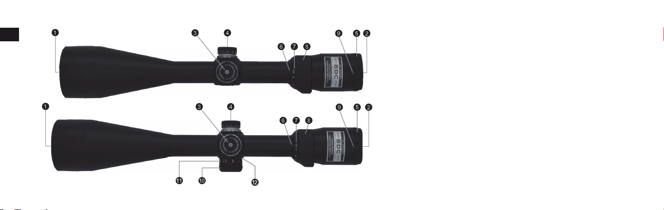
1. Nomenclature
En
4
Fig. 1-1
Fig. 1-2
2.5-10×40
2.5-10×50
3.5-14×40 SF
3.5-14×50 SF
1 Objective lens
2 Eyepiece lens
3 Elevation adjustment turret
4 Windage adjustment turret
5 Eyepiece adjustment
6 Power index
7 Power scale
8 Power selector ring
9 Diopter index dot
0 Side focus adjustment turret
a Distance scale
b Distance index
Page 5
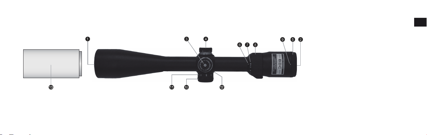
Fig. 1-3
4.5-18×40 SF
1 Objective lens
2 Eyepiece lens
3 Elevation adjustment turret
4 Windage adjustment turret
5 Eyepiece adjustment
6 Power index dot
7 Power scale
8 Power selector ring
9 Diopter index dot
0 Side focus adjustment turret
a Distance scale
b Distance index
c Sunshade
En
5
Page 6
En
En
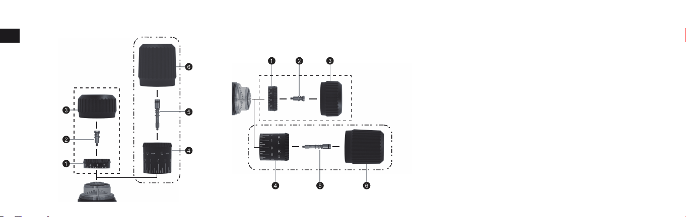
Elevation adjustment Windage adjustment
Supplied
Shipped
attached to
riflescope
Shipped attached to
riflescope
Supplied
1 Low profile turret
2 Screw for low profile turret
3 Cap for low profile turret
4 High profile turret
5 Screw for high profile turret
6 Cap for high profile turret
Fig. 1-5
Fig. 1-4
6
Fig. 1-5
Page 7
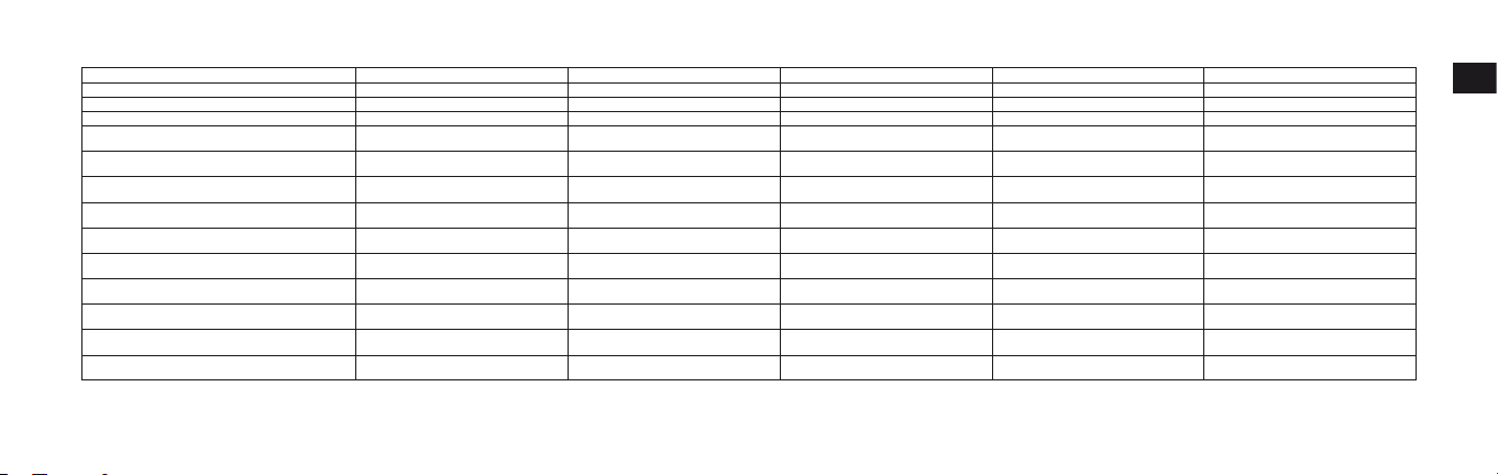
2. Specifications
Actual Magnification 2.5-10× 2.5-10× 3.5-14× 3.5-14× 4.5-18×
Objective Diameter (mm) 40 50 40 50 40
Exit Pupil* (mm) 4 5 2.9 3.6 2.2
Eye Relief** (mm)
Tube Diameter (mm)
Objective Tube Diameter (mm)
Outside Diameter of Eyepiece (mm)
Adjustment Graduation 1 click: 7 mm @ 100 m
Max Internal Adjustment
(Elevation & Windage)
Parallax Setting (m)
Field of View at 100 m/yd s** (m)
Length (mm)
Weight (g)
*at maximum magnification **(at minimum magnification)-(at maximum magnification) ***MOA = Minute of Angle
Model 2.5-10×40 2.5-10×50 3.5-14×40 SF 3.5-14×50 SF 4.5-18×40 SF
***(MOA)
(in)
(in)
(in)
(in)
(yd)
(ft)
(in)
(oz)
97-97
4.0-4.0
25.4
1
50.3
1.98
44
1.73
1 click: 1/4 in @ 100 yd
70 70 55 55 40
91.44
100
13.5-3.3
40.4-9.9
319
12.6
435
15.3
97-97
4.0-4.0
25.4
1
60.3
2.37
44
1.73
1 click: 7 mm @ 100 m
1 click: 1/4 in @ 100 yd
91.44
100
13.5-3.3
40.4-9.9
347
13.7
510
18.0
97-97
4.0-4.0
25.4
1
50.3
1.98
44
1.73
1 click: 7 mm @ 100 m
1 click: 1/4 in @ 100 yd
45.72-∞
50-∞
9.5-2.4
28.6-7.2
345
13.6
490
17.3
97-97
4.0-4.0
25.4
1
60.3
2.37
44
1.73
1 click: 7 mm @ 100 m
1 click: 1/4 in @ 100 yd
45.72-∞
50-∞
9.5-2.4
28.6-7.2
364
14.3
550
19.4
1 click: 3.5 mm @ 100 m
1 click: 1/8 in @ 100 yd
97-97
4.0-4.0
25.4
50.3
1.98
44
1.73
45.72-∞
50-∞
7.5-1.9
22.4-5.6
345
13.6
485
17.1
En
1
7
Page 8
En
En
8
3. Instructions
(1) Focusing
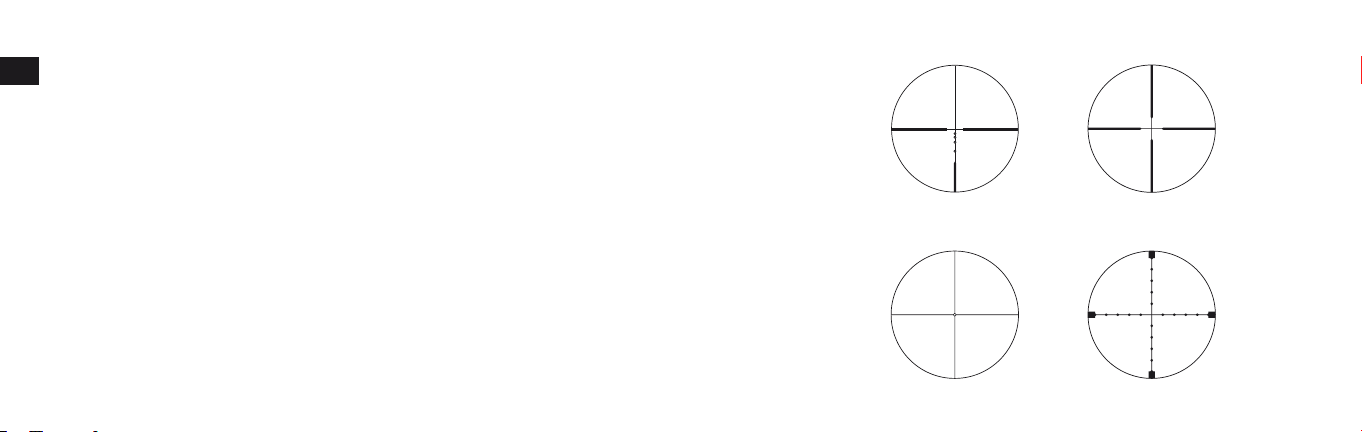
1 Look through the eyepiece with your eye positioned about 10 cm (4 in) away from the eyepiece to see the BDC reticle (Fig. 3-1),
the Duplex reticle (Fig. 3-2), the Fine Crosshair w/Dot reticle (Fig. 3-3), or the Mildot reticle (MILstandard) (Fig. 3-4). Be sure
your eye is positioned with proper alignment and with proper eye relief, otherwise the view will “black out.”
2 Point the objective end of the scope at the sky (NOT point it at the sun) or at a plain unpatterned wall.
3 Turn the eyepiece adjustment counter-clockwise and then turn it clockwise until the reticle appears sharp.
(2) Magnification
• The PROSTAFF 5 Riflescope has variable magnification. For details, see “2. Specifications”.
To change powers, rotate the power selector ring until the desired magnification appears adjacent to the power index dot.
BDC reticle
Fig. 3-1 Fig. 3-2
Duplex reticle
Fine Crosshair with Dot reticle Mildot reticle (MIL standard)
Fig. 3-3 Fig. 3-4
Page 9

(3) Adjustment of the riflescope
Sighting through the riflescope, align the rifle with your aiming point on the target and shoot a trial round. If the bullet does not hit the aiming point, adjust the elevation and windage as follows:
• If the bullet hits under the aiming point, turn the elevation adjustment turret (counter-clockwise) in the direction of the arrow marked “U” for up. If the bullet hits high, turn the elevation adjustment turret (clock-
wise) in the direction of the arrow marked “D” for down.
• If the bullet hits to the right of the aiming point, turn the windage adjustment turret (clockwise) in the direction of the arrow marked “L” for left. If the bullet hits to the left of the aiming point, turn the windage
adjustment turret (counter-clockwise) in the direction of the arrow marked “R” for right.
• For the high profile turret, adjustment is made by turning the turret by hand. If the bullet hits under the aiming point, turn the turret in the direction of the arrow marked “U”. If the bullet hits to the left of the
aiming point, turn the turret in the direction of the arrow marked “R”.
• After the reticle has been adjusted to the point of impact, replace the turret cap for both the windage and elevation adjustment turrets.
En
9
Page 10
En
(4) Zero setting of adjustment turrets
En
The elevation adjustment and windage adjustment turrets have a retracting system. After the reticle has been adjusted to the point of impact, pull out the
elevation adjustment or windage adjustment turret.
The turret can now be turned freely. Align the zero number to the index line to set the zero setting, and then release the turret. The turret automatically
retracts to the original position.
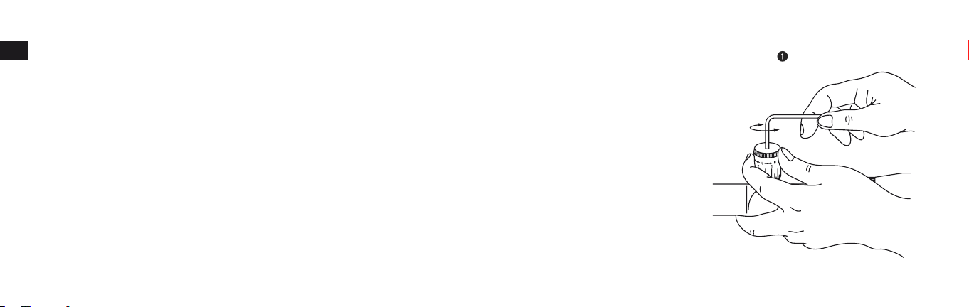
(5) Changing the turret*
Remove the turret cap by turning it counter-clockwise. Align the turret to the 0 (zero) position of the scale ring. This is to assure that the scale ring will be
correctly aligned to the new turret. (The alignment position should be remembered.)
With the turret held with your fingers to avoid shifting of the aligned scale ring, turn the screw in the top of the turret counter-clockwise with the supplied
hex key (1) until the screw comes out. Then remove the turret (Fig. 3-5).
Insert the new turret into position and align the scale ring to 0.
Insert the screw. By securing the turret with your fingers to avoid shifting of the scale ring, turn the screw clockwise with the supplied hex key, until the turret
is firmly secured.
*Please refer to “Supplied Item(s)” to see if your riflescope is provided with high profile turrets.
10
Fig. 3-5
Page 11

(6) Adjustable side focus
The PROSTAFF 5 Riflescope 3.5-14×40 SF, 3.5-14×50 SF, and 4.5-18×40 SF can be more precisely focused within the range of at least 45.72 m (50 yd) to infinity by rotating the side focus adjustment.
Parallax can be eliminated and sight alignment will be accurate.
Use its distance scale as a reference guide.
En
11
Page 12

En
Note:
• The windage and elevation scales of the PROSTAFF 5 Riflescope 2.5-10×40, 2.5-10×50, 3.5-14×40 SF, and 3.5-14×50 SF are calibrated in divisions of 1/4 minute of angle with a click at intervals of 1/4 minute of
En
angle (1 division).
• The windage and elevation scales of the PROSTAFF 5 Riflescope 4.5-18×40 SF are calibrated in divisions of 1/8 minute of angle with a click at intervals of 1/8 minute of angle (1 division).
• When adjusting the reticle to the point of aim, remember that 1 minute of angle equals approximately 2.54 cm (1 in) at 91.44 m (100 yd).
Therefore, if the impact point is 5.08 cm (2 in) low and 2.54 cm (1 in) right at 91.44 m (100 yd) Parallax Setting, you should adjust 2 minutes of angle up and 1 minute of angle left.
In the case of 45.72 m (50 yd) Parallax Setting, the adjusting value is 2×. In the case of 68.58 m (75 yd) Parallax Setting, the adjusting value is 1.5×.
12
Page 13

Maintenance
(1) Lens cleaning
To remove dirt or fingerprints, soak gauze or lens cleaning paper (silicon-free paper sold at camera retailers) with a small quantity of absolute alcohol (available from drugstores) and lightly wipe off the affected
areas.
Wiping with a handkerchief or leather may damage the lens surface and is not recommended.
Dust may scratch the lens surface or corrode the lens.
Brush dust off using a soft oil-free brush.
(2) Scope exterior
Use a soft dry cloth to wipe off any dirt or fingerprints that might accumulate.
It is not necessary to oil the scope's surface.
(3) Windage/elevation adjustments
These adjustments are permanently lubricated. Do not attempt to lubricate them. Cover them with the caps supplied, except when adjusting them, to keep out dust and dirt.
En
13
Page 14

En
(4) Eyepiece adjustment
En
This adjustment is permanently lubricated. Do not attempt to lubricate it.
(5) Power selector ring
No lubrication is required for the power selector ring.
Do not pull up or remove the rubber covering on the power selector ring.
14
Page 15

Waterproof models:
The riflescope is waterproof, and will suffer no damage to the optical system if submerged or dropped in water to a maximum depth of 1 m (3 ft 3 in) for up to 10 minutes.
The riflescope offers the following advantages:
• Can be used in conditions of high humidity, dust and rain without risk of damage.
• Nitrogen-filled design makes it resistant to condensation and mold.
Observe the following precautions when using the riflescope:
• The riflescope should not be operated nor held in running water.
• Any moisture should be wiped off before adjusting movable parts (adjustment turret, eyepiece, etc.) of the riflescope to prevent damage and for safety reasons.
To keep your riflescope in optimal condition, Nikon Vision recommends regular servicing by an authorized dealer.
Specifications and equipment are subject to change without any notice or obligation on the part of the manufacturer
En
15
Page 16

En
Fr
En
Bravo pour votre choix : votre nouvelle lunette de visée Nikon PROSTAFF 5 est un parfait exemple de la robustesse, de la longévité et de la précision des instruments d’optique Nikon - des qualités importantes pour tout
tireur sérieux.
Que vous utilisiez votre lunette pour la chasse ou pour le tir à la cible, la procédure de montage est la même. Un jeu de bagues de montage d’acier de haute qualité d’un diamètre standard de 25,4 mm (1 pouce) est
nécessaire au montage de la lunette. Pour le montage, suivez les instructions du fabricant des bagues. Après avoir monté la lunette de visée sur votre fusil, réglez l'alignement du réticule (croisée de fils) comme suit.
Fr
INFORMATIONS IMPORTANTES
IL EST IMPORTANT QUE VOTRE LUNETTE DE VISÉE NIKON SOIT CORRECTEMENT MONTÉE ET QUE VOUS SOYEZ PRUDENT LORSQUE VOUS MONTEZ LA LUNETTE DE VISÉE SUR UNE ARME.
NOUS VOUS RECOMMANDONS VIVEMENT DE FAIRE MONTER VOTRE LUNETTE DE VISÉE NIKON SUR VOTRE ARME PAR UN ARMURIER EXPÉRIMENTÉ ET RÉPUTÉ.
L'UTILISATEUR ACCEPTE TOUTE RESPONSABILITÉ CONCERNANT LE MONTAGE DE LA LUNETTE SUR UNE ARME ET CONCERNANT L'UTILISATION DE LA LUNETTE DE VISÉE NIKON.
VÉRIFIEZ TOUJOURS L’ÉTAT DE VOTRE SYSTÈME DE MONTAGE AVANT D’UTILISER VOTRE ARME.
COLISAGE
Boîtier ··············································1 Tourelle haute (4.5-18×40 SF uniquement) ···························2 Clé hexagonale (4.5-18×40 SF uniquement) ··············1
Protecteur d'oculaire ··········· Capuchon de tourelle haute (4.5-18×40 SF uniquement) ·····2
Capuchon d'objectif ············
16
············ 1 paire
Pare-soleil (4.5-18×40 SF uniquement) ································· 1
Page 17

En
Précautions
(1) Ne regardez PAS le soleil par la lunette de visée. Vous vous abîmeriez la vue de façon irrémédiable. Cette précaution s'applique à tous les instruments d'optique, comme les appareils photo et les jumelles.
(2) La lunette de visée est étanche à l'humidité et la poussière. Vous pouvez l'utiliser en toute sécurité sous la pluie et dans les environnements poussiéreux. Pour conserver l'extérieur de la lunette en bon état, nous vous
recommandons de la sécher et de la nettoyer avant de la ranger. Utilisez un chiffon doux pour nettoyer les parties métalliques, et utilisez des papiers pour objectif photo pour nettoyer les lentilles de la lunette.
Pour régler le réticule pour la chasse, vous devrez tout d'abord déterminer la portée standard ; réglez ensuite le réticule sur la base de cette distance de cible. Pour des cibles qui débordent de cette distance standard, selon
vos préférences, vous pouvez régler simplement la position du réticule par rapport à la cible, ou bien effectuer une correction de trajectoire.
Nous espérons que votre nouvelle lunette de visée Nikon PROSTAFF 5 vous procurera de longues années de satisfaction. Profitez-en, mais avant tout, respectez toujours les consignes de sécurité en matière de tir.
N.B. : l'exportation des produits* objets de ce manuel risque d'être sujette aux lois en vigueur dans le pays exportateur. La mise en œuvre d'un processus d'exportation approprié, comme l'obtention d'une licence d'exportation, peut s'avérer nécessaire.
*Produits : matériel et informations techniques connexes (y compris le logiciel)
Fr
17
Page 18

En
Fr
En
1. Nomenclature
Fr
18
Fig. 1-1
Fig. 1-2
2.5-10×40
2.5-10×50
3.5-14×40 SF
3.5-14×50 SF
1 Objectif
2 Oculaire
3 Tourelle de réglage de hausse
4 Tourelle de réglage de dérive
5 Réglage d’oculaire
6 Point d’index de puissance
7 Échelle de puissance
8 Bague de sélection de puissance
9 Point d’index de dioptrie
0 Tourelle latérale de mise au point
a Échelle de distance
b Index de distance
Page 19

En
Fig. 1-3
4.5-18×40 SF
1 Objectif
2 Oculaire
3 Tourelle de réglage de hausse
4 Tourelle de réglage de dérive
5 Réglage d’oculaire
6 Point d’index de puissance
7 Échelle de puissance
8 Bague de sélection de puissance
9 Point d’index de dioptrie
0 Tourelle latérale de mise au point
a Échelle de distance
b Index de distance
c Pare-soleil
Fr
19
Page 20

En
Fr
En
Réglage de hausse Réglage de dérive
Colisage
1 Tourelle basse
Fr
Livrés
montés sur
la lunette
Livrés montés sur la
lunette
Colisage
2 Vis de tourelle basse
3 Capuchon de tourelle basse
4 Tourelle haute
5 Vis de tourelle haute
6 Capuchon de tourelle haute
Fig. 1-5
Fig. 1-4
20
Fig. 1-5
Page 21

En
2. Caractéristiques
Grossissement réel 2,5-10× 2,5-10× 3,5-14× 3,5-14× 4,5-18×
Diamètre d’objectif (mm) 40 50 40 50 40
Pupille de sortie* (mm) 4 5 2,9 3,6 2,2
Dégagement oculaire** (mm)
Diamètre de tube (mm)
Diamètre de tube d’objectif (mm)
Diamètre extérieur d’oculaire (mm)
Graduations de réglage 1 clic = 7 mm à 100 m
Réglage interne maximal
(hausse et dérive)
Réglage de parallaxe (m)
Champ linéaire perçu à 100 m/yards** (m)
Longueur (mm)
Poids (g)
*au grossissement maximum **(au grossissement minimum)-(au grossissement maximum) ***MOA = Minute d’angle
Modèle 2.5-10×40 2.5-10×50 3.5-14×40 SF 3.5-14×50 SF 4.5-18×40 SF
(pouces)
(pouces)
(pouces)
(pouces)
***(MOA)
(yards)
(pieds)
(pouces)
97-97
4,0-4,0
25,4
1
50,3
1,98
44
1,73
1 clic = 1/4 pouce à 100 yards
70 70 55 55 40
91,44
100
13,5-3,3
40,4-9,9
319
12,6
(oz)
435
15,3
97-97
4,0-4,0
25,4
1
60,3
2,37
44
1,73
1 clic = 7 mm à 100 m
1 clic = 1/4 pouce à 100 yards
91,44
100
13,5-3,3
40,4-9,9
347
13,7
510
18,0
97-97
4,0-4,0
25,4
1
50,3
1,98
44
1,73
1 clic = 7 mm à 100 m
1 clic = 1/4 pouce à 100 yards
45,72-∞
50-∞
9,5-2,4
28,6-7,2
345
13,6
490
17,3
97-97
4,0-4,0
25,4
1
60,3
2,37
44
1,73
1 clic = 7 mm à 100 m
1 clic = 1/4 pouce à 100 yards
45,72-∞
50-∞
9,5-2,4
28,6-7,2
364
14,3
550
19,4
1 clic = 3,5 mm à 100 m
1 clic = 1/8 pouce à 100 yards
97-97
4,0-4,0
25,4
50,3
1,98
44
1,73
45,72-∞
50-∞
7,5-1,9
22,4-5,6
345
13,6
485
17,1
Fr
1
21
Page 22

En
Fr
En
Fr
22
3. Utilisation
(1) Mise au point
1
Regardez dans l’oculaire, l’œil placé à 10 cm environ (4 pouces) de la lentille oculaire, pour voir le réticule BDC (Fig. 3-1), le réticule
Duplex (Fig. 3-2), le réticule à croisée de fils fins avec point (Fig. 3-3) ou le réticule Mil-Dot (gradué en milliradians) (Fig. 3-4).
Assurez-vous que votre œil est correctement aligné et positionné à la bonne distance, afin d'éviter que votre vue soit "bouchée".
2 Pointez l’objectif de la lunette vers le ciel (mais PAS en direction du soleil) ou vers un mur de couleur unie.
3 Faites tourner la molette de réglage du viseur dans le sens inverse des aiguilles d'une montre puis dans le sens des aiguilles d'une
montre, jusqu'à ce que le réticule apparaisse net.
(2) Grossissement
•
La lunette de visée PROSTAFF 5 dispose d’un grossissement variable. Pour plus de précisions, voir le point "2. Caractéristiques".
Pour changer la puissance, tournez la bague de sélection de puissance jusqu’à ce que le rapport de grossissement voulu arrive à côté du point d’index de puissance.
Réticule BDC
Fig. 3-1 Fig. 3-2
Réticule à croisée de fils fins avec point
Fig. 3-3 Fig. 3-4
Réticule Duplex
Réticule Mil-Dot (gradué en milliradians)
Page 23

En
(3) Réglage de la lunette de visée
Regardez dans la lunette de visée, alignez l'arme avec le point visé sur la cible et tirez un coup d'essai. Si la balle ne touche pas le point de visée, réglez la hausse et la dérive de la manière suivante :
• Si la balle touche en-dessous du point visé, faites tourner la tourelle de réglage de la hausse (dans le sens inverse des aiguilles d'une montre) en suivant le sens de la flèche marquée "U" (pour Up ou Haut). Si la
balle est trop haute, faites tourner la tourelle de réglage (dans le sens des aiguilles d'une montre) en suivant le sens de la flèche marquée "D" (Pour Down ou Bas).
• Si la balle touche à droite du point visé, faites tourner la tourelle de réglage de la dérive (dans le sens des aiguilles d'une montre) en suivant le sens de la flèche marquée "L" (pour Left ou Gauche). Si la balle est à
gauche, faites tourner la tourelle de réglage (dans le sens inverse des aiguilles d'une montre) en suivant le sens de la flèche marquée "R" (pour Right ou Droite).
• Le réglage de la tourelle haute s’effectue en la faisant tourner à la main. Si la balle touche en-dessous du point visé, faites tourner la tourelle en suivant le sens de la flèche marquée "U" (pour Up ou Haut). Si la
balle touche à gauche du point visé, faites tourner la tourelle en suivant le sens de la flèche marquée "R" (pour Right ou Droite).
• Quand le réticule est bien réglé sur le point d'impact, reposez les capuchons sur les deux tourelles de dérive et de hausse.
Fr
23
Page 24

En
Fr
En
(4) Réglage du zéro des deux tourelles
Les tourelles de réglage de hausse et de dérive sont équipées d'un système rétractable. Une fois que le réticule a été réglé sur le point d'impact, tirez sur la
tourelle pour procéder au réglage du zéro.
Fr
Elle tourne maintenant librement. Alignez le chiffre zéro sur le trait de repère, puis relâchez la tourelle. Elle revient automatiquement à sa position initiale.
(5) Remplacement de la tourelle*
Retirez le capuchon de tourelle en le faisant tourner dans le sens inverse des aiguilles d’une montre. Alignez la tourelle sur la position 0 (zéro) de la bague
graduée. Cela garantit le bon alignement de la nouvelle tourelle sur cette dernière (en notant la position d’alignement pour vous en souvenir).
Tout en tenant la tourelle avec les doigts pour éviter de fausser l’alignement de la bague graduée, dévissez dans le sens inverse des aiguilles d’une montre la
vis située en haut de la tourelle à l’aide de la clé hexagonale fournie (1) jusqu’à ce qu’elle sorte. Retirez ensuite la tourelle (Fig. 3-5).
Insérez la nouvelle tourelle en place et alignez la bague graduée sur le 0.
Insérez la vis. Tout en maintenant la tourelle avec les doigts pour éviter de décaler la bague graduée, faites tourner la vis dans le sens des aiguilles d’une
montre à l’aide de la clé hexagonale fournie jusqu’à ce que la tourelle soit solidement fixée.
24
*Veuillez vous reporter à la section "Colisage" pour savoir si votre lunette de visée est livrée avec des tourelles hautes.
Fig. 3-5
Page 25

En
(6) Tourelle latérale de mise au point
Sur les lunettes PROSTAFF 5 3.5-14×40 SF, 3.5-14×50 SF et 4.5-18×40 SF, il est possible d’affiner la mise au point sur la plage d’au moins 45,72 m (50 yards) à l’infini en faisant tourner la tourelle latérale.
Il est possible de supprimer la parallaxe pour obtenir un alignement précis de visée.
Servez-vous de l'échelle graduée de distance pour vous guider.
Fr
25
Page 26

En
Fr
En
Remarque :
• Les échelles de dérive et de hausse des lunettes de visée PROSTAFF 5 2.5-10×40, 2.5-10×50, 3.5-14×40 SF et 3.5-14×50 SF sont graduées en quarts de minute d’angle et marquent un cran au passage de chaque
graduation (1/4 minute d’angle).
• Les échelles de dérive et de hausse de la lunette de visée PROSTAFF 5 4.5-18×40 SF sont graduées en huitièmes de minute d’angle et marquent un cran au passage de chaque graduation (1/8 minute d’angle).
Fr
• Lorsque vous réglez le réticule sur le point de visée, n'oubliez pas qu'une minute d'angle équivaut à peu près à 2,54 cm (1 pouce) à 91,44 m (100 yards).
En conséquence, si le point d’impact se trouve 5,08 cm (2 pouces) trop bas et 2,54 cm (1 pouce) trop à droite, pour une parallaxe réglée à 91,44 m (100 yards), vous devrez corriger les réglages de deux minutes
d’angle vers le haut et d’une minute d’angle vers la gauche.
Dans le cas d’un réglage de parallaxe de 45,72 m (50 yards), il faudra doubler ces valeurs de correction. Avec un réglage de parallaxe de 68,58 m (75 yards), il faudra les multiplier par 1,5.
26
Page 27

En
Entretien
(1) Nettoyage de la lentille
Pour retirer la poussière et les traces de doigts, imbibez une feuille de papier de soie pour objectif (papier sans silicone vendu dans les magasins d'appareils photo) d'une petite quantité d'alcool pur (en vente dans
les drogueries) et essuyez légèrement les zones concernées.
II est déconseillé d'utiliser un mouchoir ou une peau de chamois, car cela pourrait abîmer la surface de l'objectif.
La poussière peut rayer ou attaquer la surface de la lentille.
Époussetez-la avec un pinceau non gras à poils souples.
(2) Surface extérieure de la lunette
Utilisez un chiffon doux et sec pour enlever la poussière et les traces de doigts.
II est inutile de graisser la surface de la lunette.
(3) Réglage de la dérive et de la hausse
Les tourelles de réglage possèdent un système de graissage permanent. N'essayez pas de les graisser. Pour les protéger de la poussière et de la saleté, utilisez les capuchons fournis - sauf pendant le réglage.
Fr
27
Page 28

En
Fr
En
(4) Réglage de l'oculaire
Ce réglage possède un système de graissage permanent. N'essayez pas de le graisser.
(5) Bague de sélection de puissance
Fr
II n'est pas nécessaire de graisser la bague de sélection de puissance.
Ne tirez pas sur le caoutchouc de la bague de sélection de puissance et n'essayez pas de l'enlever.
28
Page 29

En
Modèles étanches :
Les lunettes de visée étant étanches, leur système optique ne s’abîmera pas si elles sont immergées ou tombent dans l’eau, jusqu’à une profondeur maximale de 1 m (3 pieds et 3 pouces) et pendant 10 minutes au
plus.
Cette lunette de visée présente les avantages suivants :
• Elle est utilisable par forte humidité, poussière et pluie sans risques de dommages.
• Sa conception à injection d'azote la rend résistante à la condensation et aux moisissures.
Observez les précautions suivantes lorsque vous utilisez la lunette de visée :
• N'utilisez pas votre lunette de visée sous l'eau courante.
• En cas d'humidité, essuyez votre lunette avant d'ajuster les parties mobiles (tourelle de réglage, oculaire, etc.) pour éviter tout dégât et pour des raisons de sécurité.
Pour maintenir votre lunette de visée dans un état optimal, Nikon Vision recommande un entretien régulier par un revendeur agréé.
Fr
Les caractéristiques techniques et l’équipement peuvent être modifiés sans préavis ni obligation de la part du fabricant.
29
Page 30

Memo
Page 31

Memo
Page 32

In the event that you should require service for your Nikon RIFLESCOPE,
in case of USA market, please send it directly to:
Nikon Scope Service
841 Apollo Street, Suite 100
El Segundo, CA. 90245-4721
1-800-Nikon SV.
In other market, please bring it to dealer from which you purchased it.
Manufacturer:
3-25, Futaba 1-chome, Shinagawa-ku, Tokyo 142-0043, Japan
Printed in the Philippines (726C)1E/1301
 Loading...