

Nikon 18-55 f, JAA79201, JAA79251 Repair manual
作成承認印 配布許可印
JAA79201-R.3669.A
JAA79201
Copyrighc2005 by Nikon Corporation.
All Rights Reserved.
無断転載を禁ず
!!
Printed in Japan May 2005
AF-S DX Nikkor ED
18-55/3.5-5.6G
JAA79251
Black
Silver
REPAIR MANUAL
M
サービス
計画課

JAA79251-R.3669.A
- M1
・ AF-S DX 18-55/3.5-5.6G
-
Specications
Type of lens: G-type AF-S DX Zoom-Nikkor lens with built-in CPU and Nikon bayonet
mount (Specially designed for use with Nikon digital SLR – Nikon DX
format – cameras)
Focal length: 18mm–55mm
Maximum aperture: f/3.5–5.6
Lens construction: 7 elements in 5 groups (1 ED and 1 aspherical lens elements)
Picture angle: 76° – 28°50´
Focal length scale: 18, 24, 35, 45, 55mm
Distance information: Output to camera body
Zoom control: Manually via separate zoom ring
Focusing: Autofocus using a Silent Wave Motor; manually via separate focus ring
Closest focus distance: 0.28m (0.9 ft.) at all zoom settings
Diaphragm: Fully automatic
Aperture range: f/3.5 to f/22 (at 18mm), f/5.6 to f/38 (at 55mm)
Exposure measurement:Via full-aperture method
Attachment size: 52mm (P = 0.75mm)
Dimensions: Approx. 69mm dia. x 74mm extension from the camera’s lens-mount ange
Weight: Approx. 210g (7.4 oz)
・Specications and designs are subject to change without any notice or obligation on the part
JAA79201-R.3669.A
- D1・ AF-S 18-55/3.5-5.6G -
#68
#113
Disassembly / Assembly / Adjustment
1. Disassembly
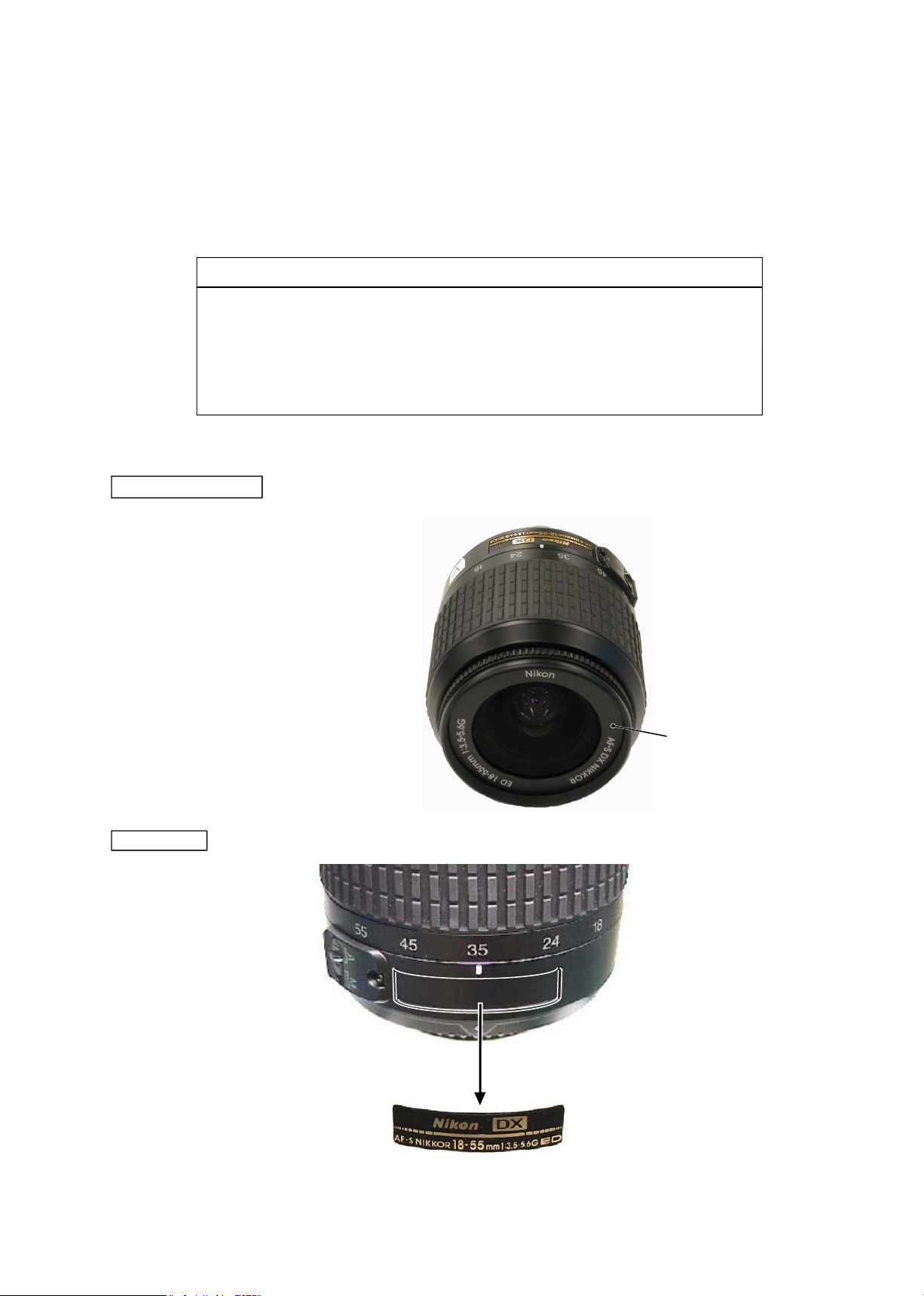
Name plate
Company name ring
Note: Detaching the name plate (#68) is NOT necessary EXCEPT replacing it.
・
The company name ring (#113)
is attached with the both-sided
adhesive tape.
Note:
①
When disassembling, make sure to memorize the processing state of wires and FPC
.
②
Because prototypes are used for "Disassembly/(Re)assembly/Adjustment", they may differ from the actual
products in forms, etc.
③
Because pictures are processed by a special method, they may differ from the actual ones in texture.
・Lead-free solder is used for this product.
・For soldering work, the special solder and soldering iron are required.
・
Do NOT mix up lead-free solder with traditional solder.
・Use the special soldering iron respectively for lead-free solder and lead solder.
They cannot be used in common.
Points to notice for Lead-free solder products
JAA79201-R.3669.A
- D2・ AF-S 18-55/3.5-5.6G -
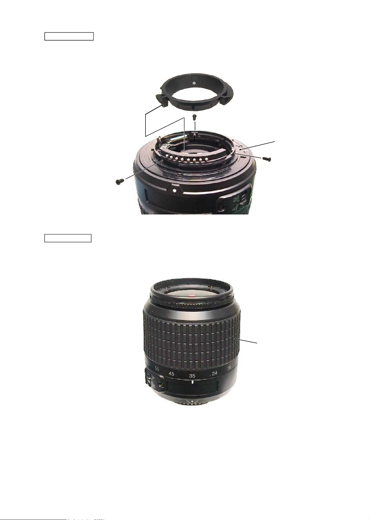
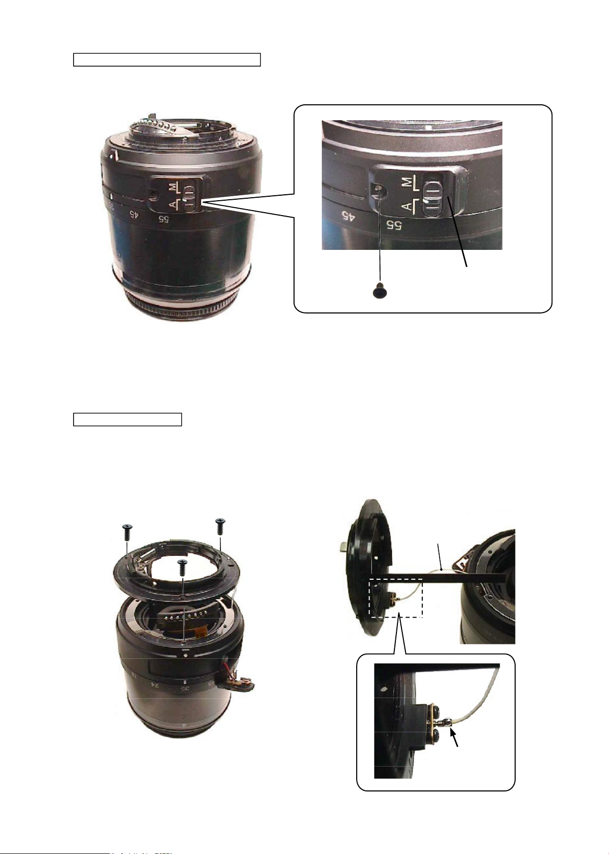
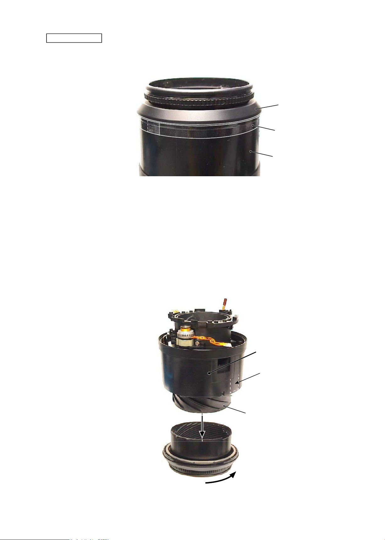
#62
Rear cover ring
・
Take out 3 screws (#91) to remove the rear cover ring (#39).
#39
#91×3
#B27
Rubber ring
・
Remove the rubber ring (#62).
JAA79201-R.3669.A
- D3・ AF-S 18-55/3.5-5.6G -
#103
#111×4
#B1
#100A
~
I×n
#52
#67×2
#B27
#B6
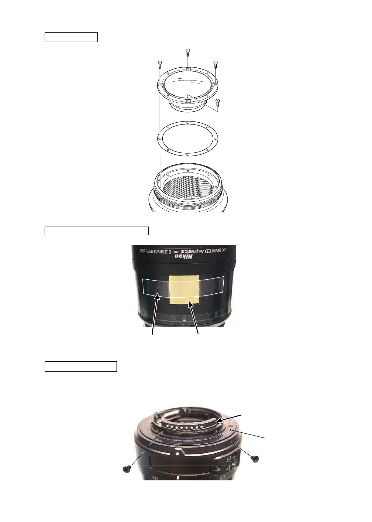
1st lens group
Distance brush hole-sealing plate
Polyester tape
・
Take out 2 screws (#67) of the contact unit (#B6) that is attached to the bayonet mount unit (#B27).
Removal of Contact unit
JAA79201-R.3669.A
- D4・ AF-S 18-55/3.5-5.6G -
・
Take out the screw (#155) to remove the M/A change-SW unit(#B22).
#155
Bayonet mount unit
・
Take out 3 screws (#78) of the bayonet mount unit (#B27) to remove the lead wire (#1131).
#1131
Remove the solder.
#78×3
#B27
Removal of M/A change-SW unit
#B22
JAA79201-R.3669.A
- D5・ AF-S 18-55/3.5-5.6G -
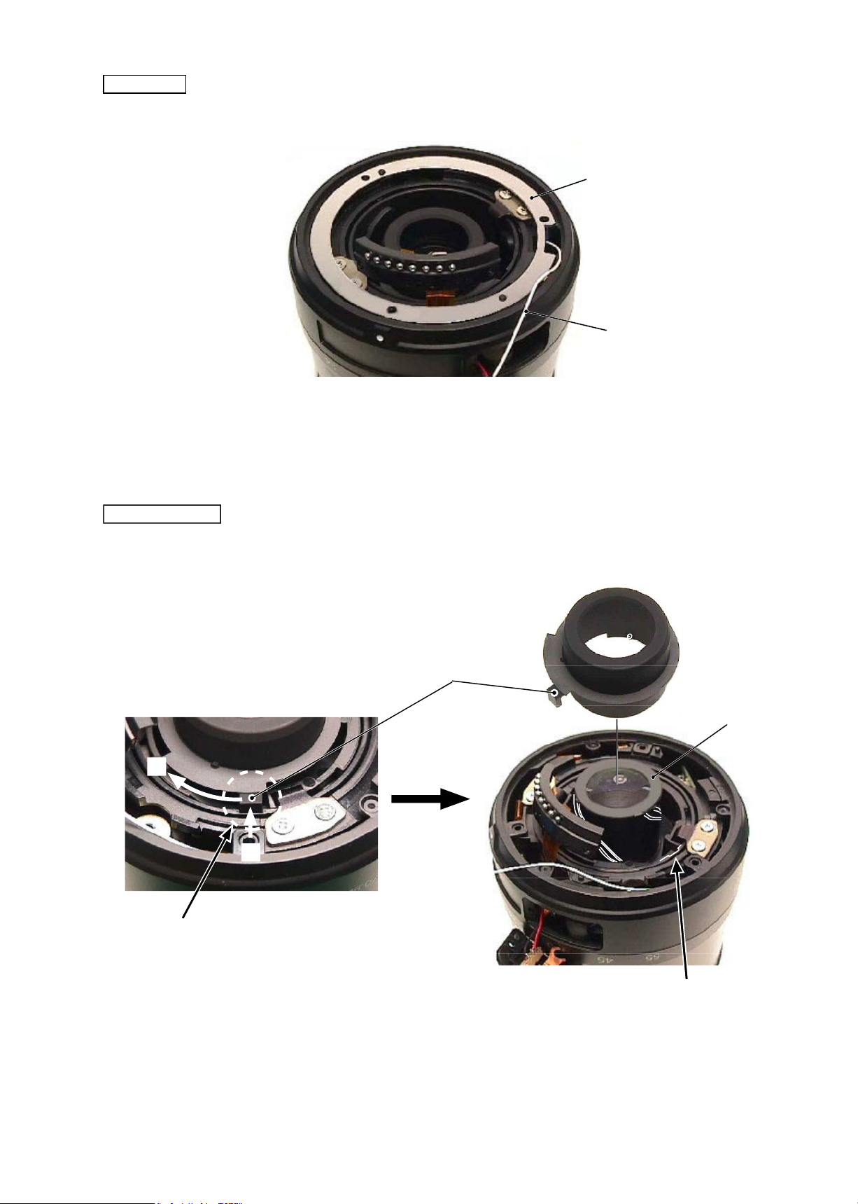
Washer
#101A~J×n
#1131
・
Remove the washers
(
#101A
~
J×n).
Flare cutter
・
Release the key part of the are cutter (#46) from the key-groove of the cam tube, then remove the are
cutter.
#46
Key part
Key-groove of Cam tube
#B24
Release the key part from the key-groove.
・
Set the zoom position to WIDE-end. While
pressing the pointed tip of the key inward,
remove the key by turning clockwise.
①
→
②
①
②
JAA79201-R.3669.A
- D6・ AF-S 18-55/3.5-5.6G -
Straight key unit
#86×2
#B25A
#86×2
#B25B
2nd lens group
#B24
JAA79201-R.3669.A
- D7・ AF-S 18-55/3.5-5.6G -
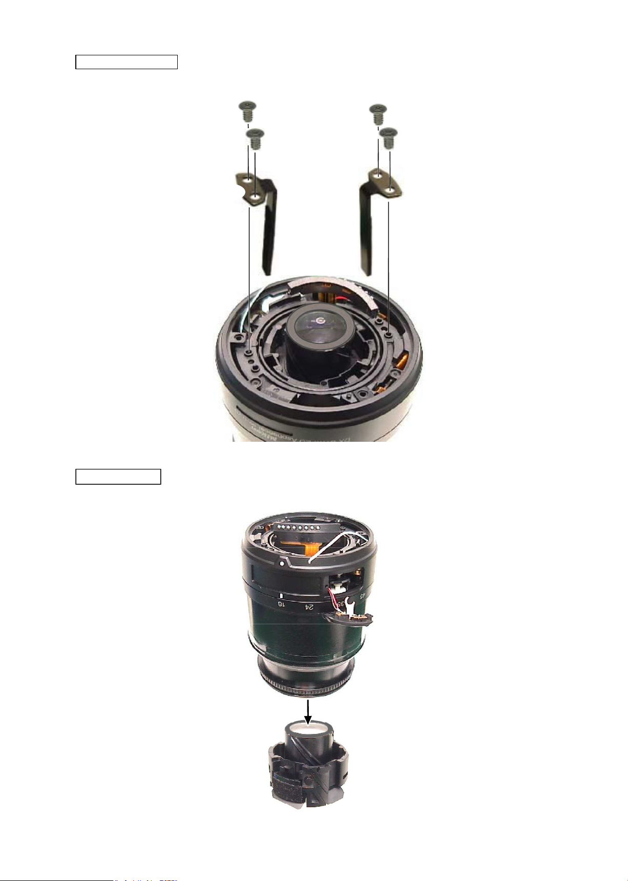
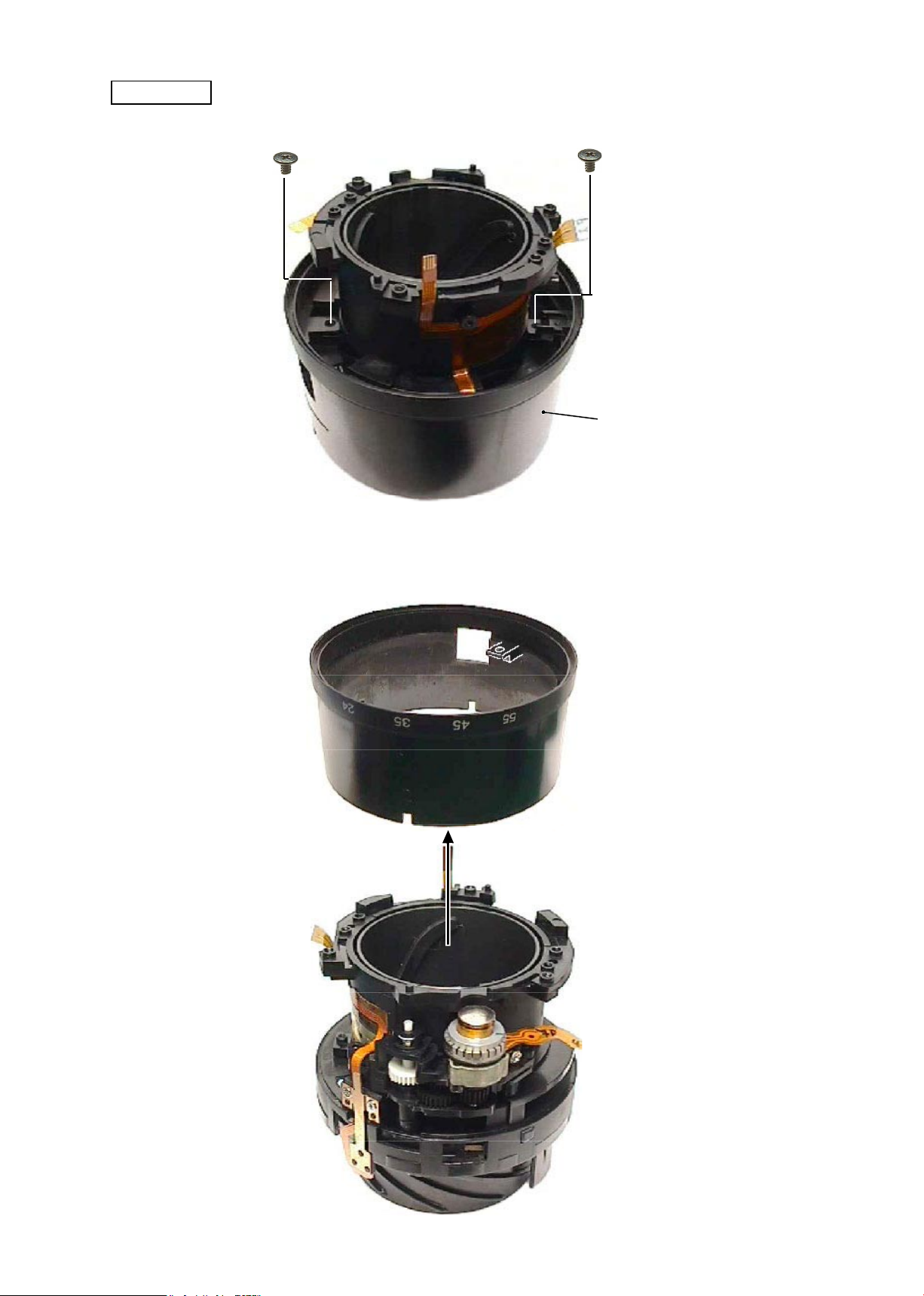
Rear xed tube
・
Set the M/A change-SW unit (#B22) to A mode. Detach it from the window of the rear xed tube (#57) and
remove the rear xed tube.
#B22
#57
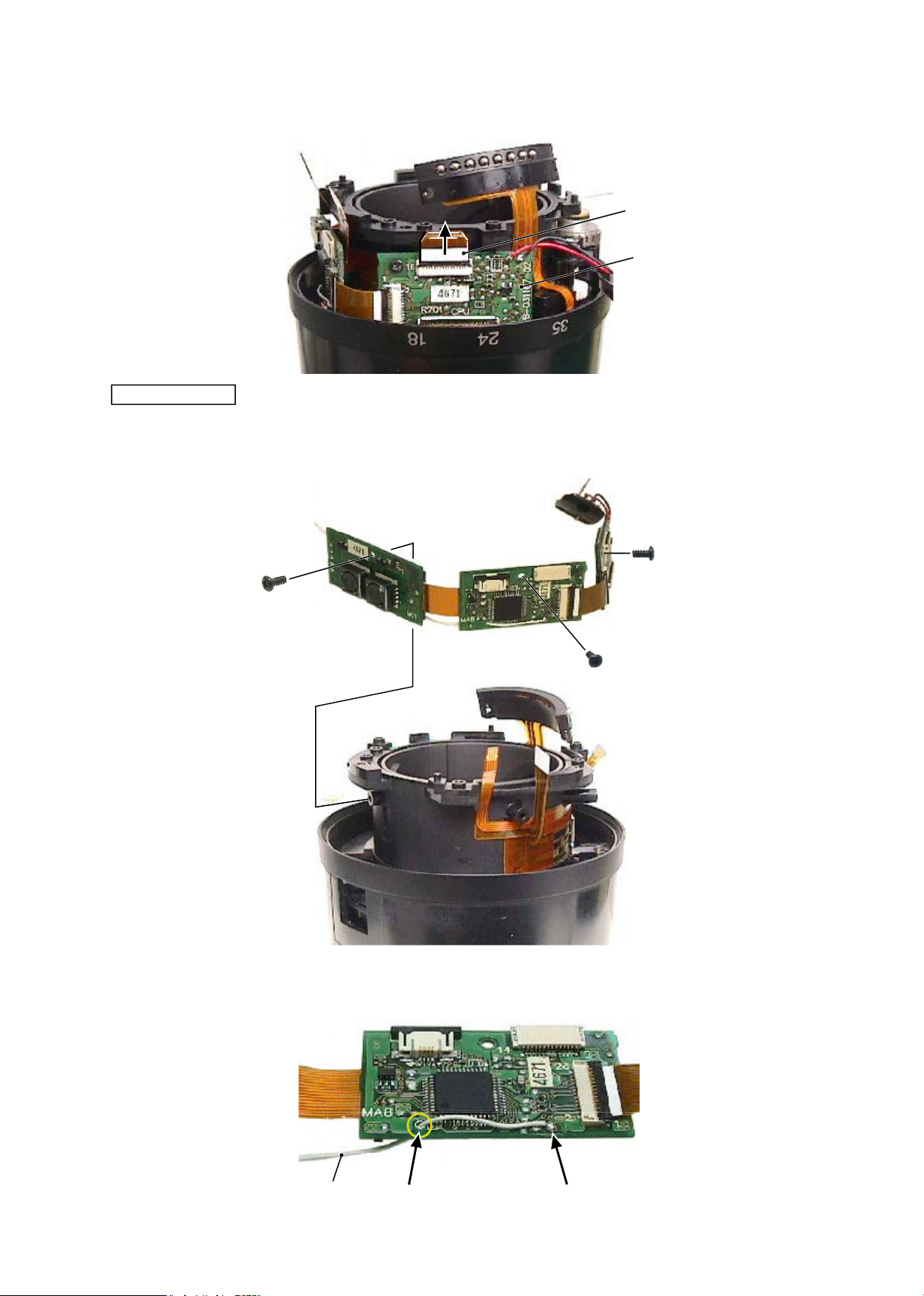
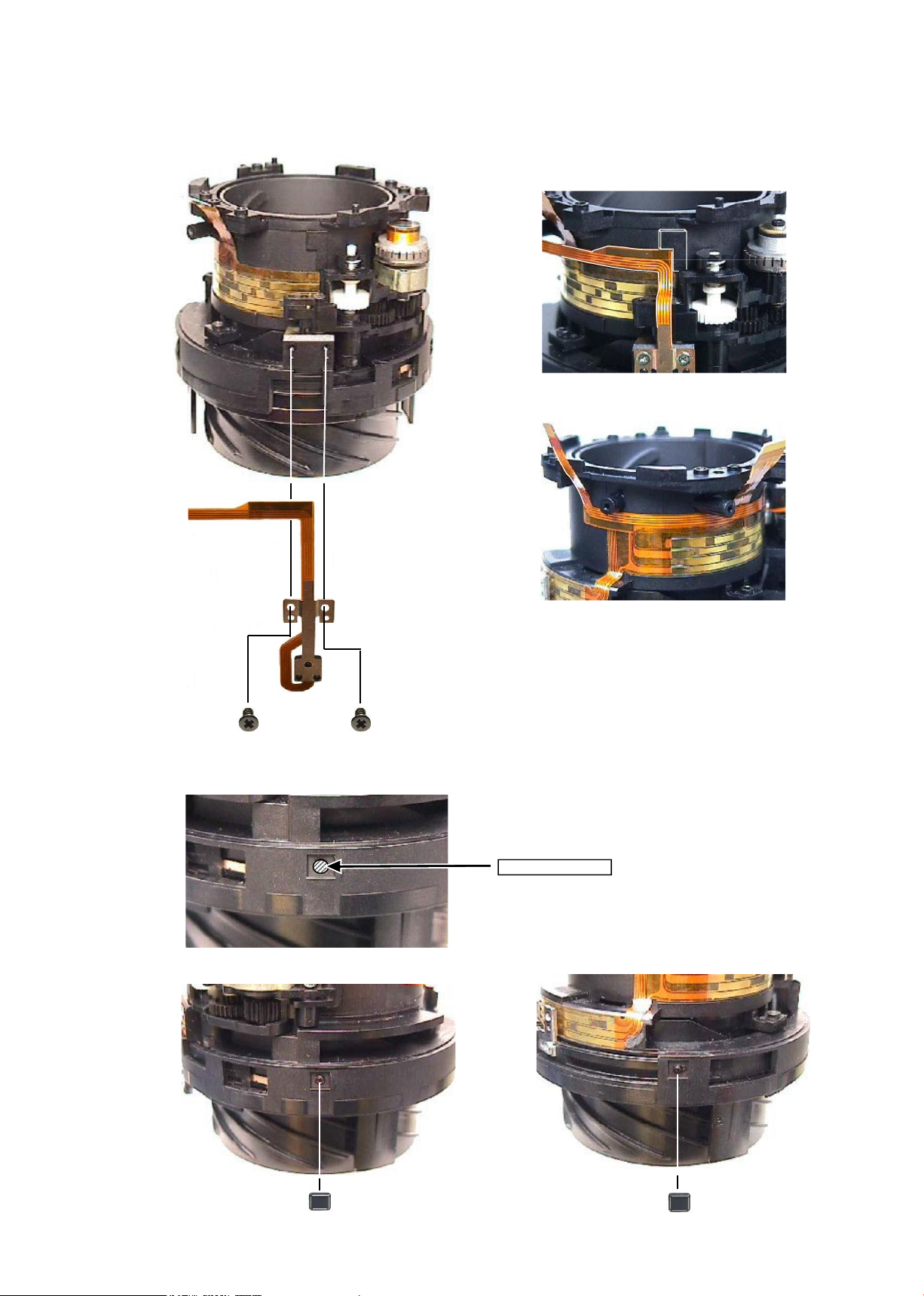
Removal of FPC from Main-PCB unit
・
Remove the SWM unit (#B501) from the main-PCB unit (#B1001).
#B501
#B1001
・
Remove the contact unit (#B6) and MR unit (#B7) from the connector of the main-PCB unit (#B1001).
#B1001
#B7
#B6
Note: Do NOT touch "A" part directly
with hand.
A
JAA79201-R.3669.A
- D8・ AF-S 18-55/3.5-5.6G -
・
Remove the zoom/distance FPC from the connector of the main-PCB unit (#B1001).
#B1001
Zoom/distance FPC
・
Remove the main-PCB unit (#B1001).
#89
#89
#89
#B1001
Main PCB unit
・
Remove the lead wire (#1131) from the main-PCB unit (#B1001).
Hole
Remove the solder.
#1131
JAA79201-R.3669.A
- D9・ AF-S 18-55/3.5-5.6G -
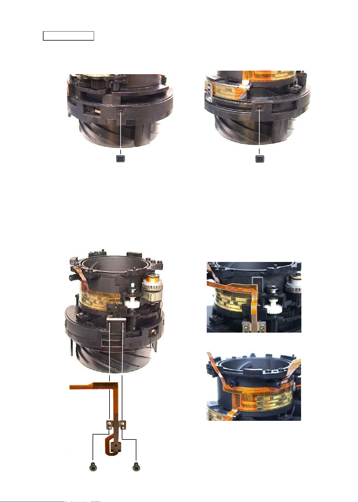
Contact unit
・
Remove the contact unit (#B6).
#B6
M/A change-SW unit
・
Remove 2 lead wires of the M/A change-SW unit (#B22) from the main PCB unit (#B1001).
#B22
Remove the solder.
#B1001
Black
Red
Zoom brush unit
#89
#B8
#52
Zoom brush unit
JAA79201-R.3669.A
- D10 ・ AF-S 18-55/3.5-5.6G -
・
Remove the polyester tape (#77) from the zoom ring (#52).
#77
#52
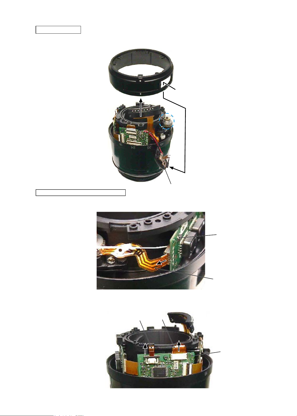
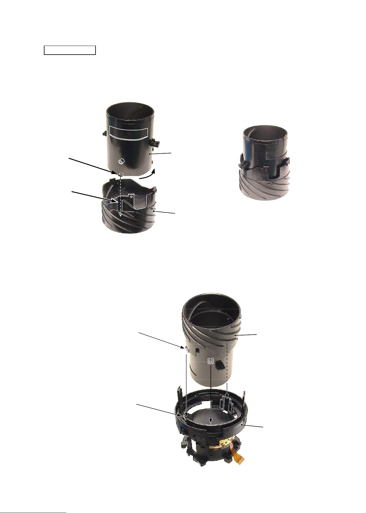
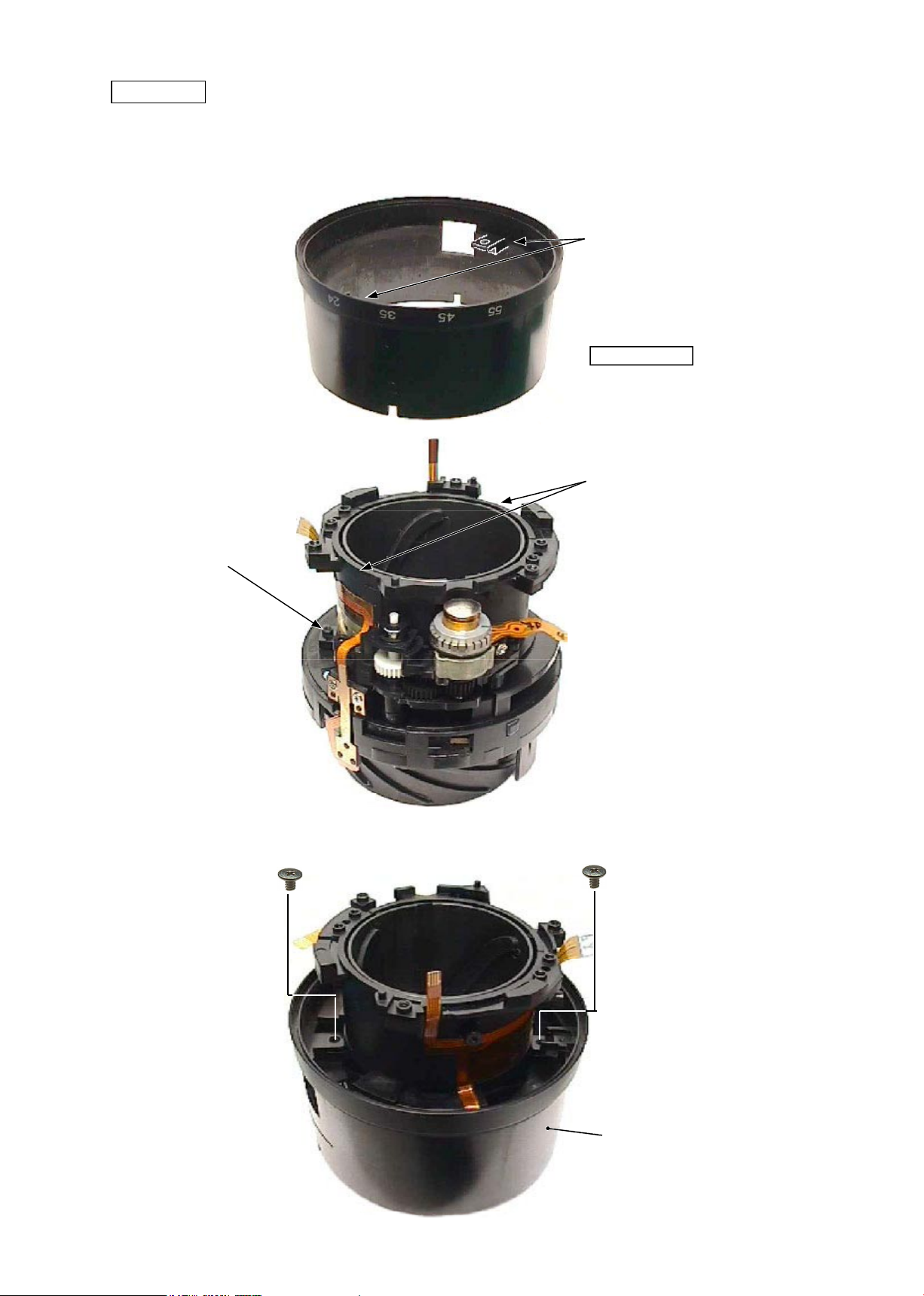
Zoom cover ring
Filter ring unit
・
While releasing the engagements of 2 keys of the focus ring, turn the lter ring unit (#B20) in the direction of
the arrow to remove it.
#
B20
Helicoid ring
Key of focus ring
Zoom ring
JAA79201-R.3669.A
- D11 ・ AF-S 18-55/3.5-5.6G -
Zoom ring
#102×2
・
Take out 2 screws (#102) that attach the zoom ring (#52).
#52
・
Detach the zoom
ring (#52) from the xed tube unit.
#52
Fixed tube unit
JAA79201-R.3669.A
- D12 ・ AF-S 18-55/3.5-5.6G -
#56
②
MR unit
・
Remove the MR unit (#B7) from the xed tube.
#56
・
Remove 2 silicon rubbers (#56) from the square grooves of the xed tube.
・
Remove the FPC of the MR unit from the xed tube.
#72
#72
#B7
Fixed tube unit
①
Silicon rubber
JAA79201-R.3669.A
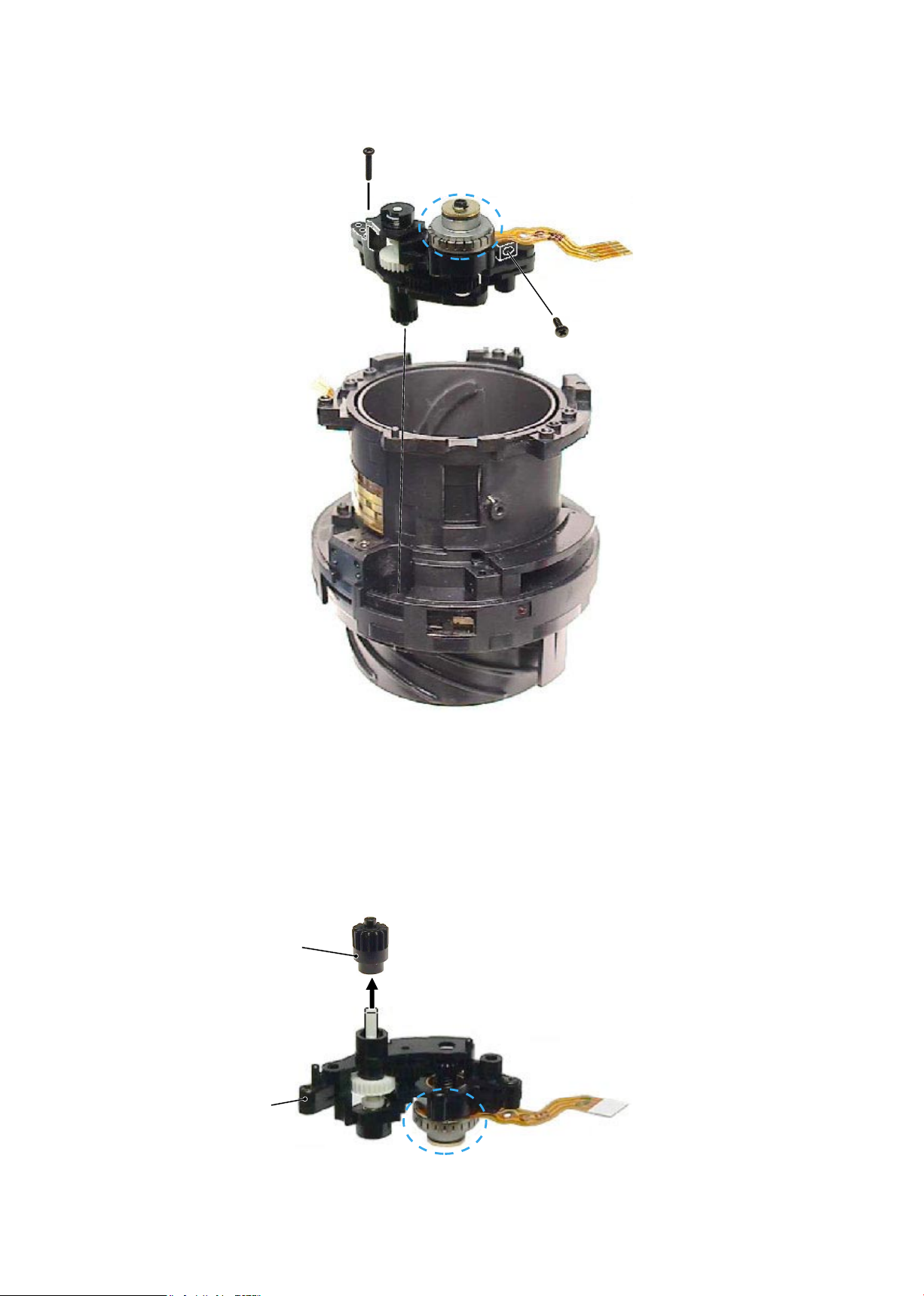
- D13 ・ AF-S 18-55/3.5-5.6G -
Gear
③
SWM unit
#B501
Do NOT touch "A" part.
A
・
Remove the SWM unit (#B501) from the xed tube.
A
#132
#131
Fixed tube
#B501
④
Gear
Note: Do NOT touch "A" part directly with hand.
JAA79201-R.3669.A
- A1・ AF-S 18-55/3.5-5.6G -
2. Assembly / Adjustment
Fixed tube unit
Helicoid ring
After assembling
・
Align the cam ring (3 grooves between convex portions on the outer diameter surface) with the helicoid ring
(3 convex cams on the inner diameter surface) and assemble the rings by turning them.
Cam ring
①
Cam tube unit (Helicoid ring, Cam ring)
・
With the cam tube unit (3 outer convex portions) being at the full up WIDE position, assemble the xed tube
(3 inner grooves between cams).
Note:
The cam ring and helicoid ring are
NOT prepared as single part of RP.
②
Cam tube unit / Fixed tube
Cam tube unit
Fixed tube
Convex portion on
the outer diameter
surface
Outer convex portion
Groove between inner cams
JAA79201-R.3669.A
- A2・ AF-S 18-55/3.5-5.6G -
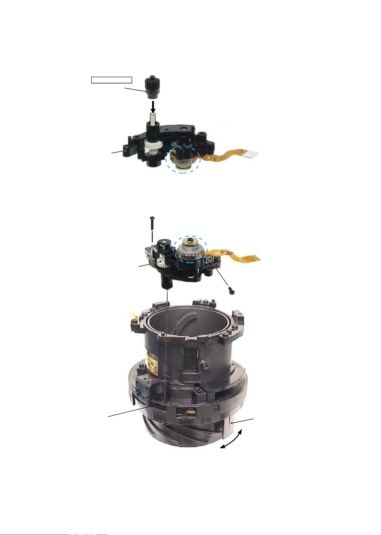
#513
③
SWM unit
・
Assemble the gear (#513) into the SWM unit (#B501).
#B501
Do NOT touch "A" part.
A
・
Assemble the SWM unit into the xed tube.
A
・
Raise the clutch gear with tweezers, and check the engagement of the segment gear tube and the ear (#513)
by turning the MF ring.
・
Raise the clutch gear with tweezers, and check it moves back downwards smoothly.
#132
#131
Clutch gear
MF ring
Grease: MZ-800S
Note: Do NOT touch "A" part.
Segment gear tube
JAA79201-R.3669.A
- A3・ AF-S 18-55/3.5-5.6G -
#56
④
MR unit
・
Assemble the MR unit (#B7) into the xed tube.
#56
・
Put the silicon rubbers (#56) into 2 square grooves of the xed tube, and press them (with ngers).
・
Attach the FPC of the MR unit on the xed tube,
and press it with ngers.
#72
#72
#B7
Square groove×2
Adhesive:
Screwlock
JAA79201-R.3669.A
- A4・ AF-S 18-55/3.5-5.6G -
Zoom ring
#102×2
・
Align 2 notches of the xed tube with 2 convex portions of the zoom ring (#52) to assemble them. Then
turn the zoom ring, and t 2 convex portions of the cam ring into 2 holes of the zoom ring.
#52
・
Fix the zoom ring (#52) with 2 screws (#102), and check the smoothness of the zoom ring’s movement.
Fixed tube unit
#52
Apply to the sliding part of the
inner diameter surface.
Grease: MZ-800S
Convex portion
Notch
Convex portion of cam ring
JAA79201-R.3669.A
- A5・ AF-S 18-55/3.5-5.6G -
Filter ring unit
#
B20
①
Turn the zoom ring in the direction
of the arrow (TELE-side).
②
While lifting the clutch gear, turn
the key of the focus ring all the
way in the direction of the arrow.
③
Align the reference line of the lter
ring unit (#B20) with “A” part of
the helicoid ring, and turn the lter
ring until it clicks.
Inspection and adjustment of output waveform of MR encoder
Helicoid ring
Apply to the sliding part
of the outer diameter
surface.
Grease: MZ-800S
Oscilloscope
(2ch type)
Rated voltage power-supply
Set value
5.0 V
100 mA
(+)
(
GND
)
・
【
Attachment diagram
】
Self-made tool
Oscilloscope
(2ch)
Oscilloscope
(1ch)
Rated voltage power-supply
(+)
Rated voltage power-supply
(-)
Self-made tool that is created with
the main PCB of AF-S 24-85
SWM unit
A
Key of Focus ring
Zoom ring
Reference line
▽
-mark
JAA79201-R.3669.A
- A6・ AF-S 18-55/3.5-5.6G -
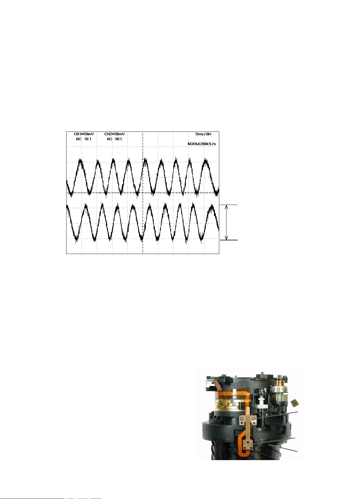
● Oscilloscope setting
V/Div (ch1) : 50 mV
V/Div (ch2) : 50 mV
Coupling : AC
Time/Div : 5 m Sec
Trigger Mode : NORMAL
Trigger Coupling : AC
・
How to inspect and adjust:
①
Conrm that the electric current and voltage of the connected rated voltage power-supply are set values, then
turn it ON.
②
Set the oscilloscope. While holding the white gear of the SWM unit with tweezers, etc, up towards the
bayonet side, turn the focus ring manually.
Note: The waveform varies according to the rotational speed of the focus ring. So change "Time/Div” setting
accordingly.
③
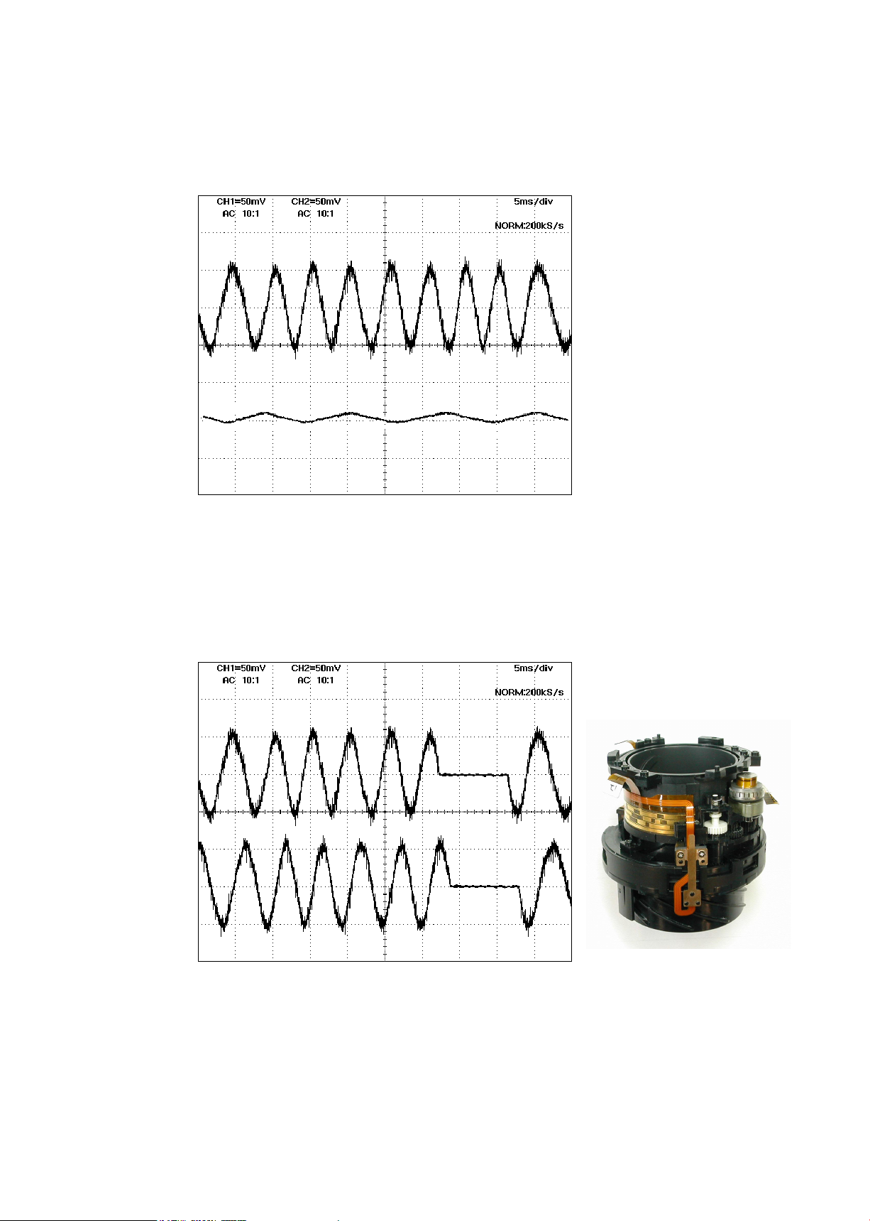
In case large waveform-noise (as shown in Fig. 1) is detected, use the FILTER function.
How to set FILTER function (e.g. DL1540 manufactured by YOKOGAWA
)
1. Press the FILTER button.
2. Select “Smooth” of the menu on screen and turn it ON.
Amplitude
CH1
CH2
Fig.1
⑥
In case the amplitude is small, disassemble up to the
stage of the zoom ring. Then if the deformation is
detected in the MR head, correct the deform of the
MR head. On the other hand, if such correction is
impossible or no deformation is detected, replace the
MR unit. (Fig.2)
Note: When adjustments are made, prevent the
magnetic surface and MR head from touching the
magnetized driver bit. Otherwise, the magnetic
data may be damaged.
MR head
Magnetic
surface
#79×2
Fig.2
Standard:
Amplitude of all pulses/
waveforms is 80mV or more.
Note:
Check the waveform by moving the
focus ring back and forth from the
innity-end to the close-end positions
entirely.
JAA79201-R.3669.A
- A7・ AF-S 18-55/3.5-5.6G -
Fixed tube unit
Fig.1
CH1
CH2
Fig.2
CH1
CH2
<
Ref.
>
● As shown in Fig. 1,
if the amplitude of only either CH1 or CH2 is small, one of the 2 screws (#218) may be
loosened, so check for it. If this is not the case, the MR head may malfunction, so replace the MR holder
unit and make a readjustment.
●
As shown in Fig. 2,
if the amplitude partially drops between the innity and the close-distance, the
magnetic data of the tape may be damaged. So replace the main xed tube unit and make a readjustment.
Replacing only the magnetic surface is impossible.
⑦ Turn off the rated voltage power-supply.
JAA79201-R.3669.A
- A8・ AF-S 18-55/3.5-5.6G -
・
While pressing the zoom aperture ring on the zoom ring (#52), attach the polyester tape (#77) to cover the
boundary line of the entire circumference of the 2 rings.
#77
#52
Zoom cover ring
Zoom brush unit
・
Assemble the zoom brush unit (#B8) into the zoom ring (#52).
Note: In order to prevent the brush from being bent when assembled, use the Z-brush
insertion sheet (J11316) and assemble the zoom brush unit (#B8).
#89
#B8
#52
Z brush insertion sheet
(J11316)
★
(6×30
)
TA-0012
★:
Newly prepared RJ tool
 Loading...