

Nikon Eclipse TI-TIRF-E, Eclipse TI-PAU, Eclipse TI-TIRF, Eclipse Ti, LU4-B5 Setup Manual
...Page 1
M456 E 10.9.NF.5
*M456EN05*
Series
TI-TIRF Illuminator Unit
TI-TIRF-E Motorized Illuminator Unit
TI-PAU Photo Activation Illuminator Unit
TI-TIRF-PAU Illuminator
LU4-B5 Beamsplitter 50/50
Setup Manual
<For Authorized Nikon Personnel>
WARNING
This manual is intended to provide setup instructions for Nikon
representatives who have attended the lecture on laser safety and have been
trained in setup operations. Attempts by others to set up the product may
lead to accidents or equipment failure. NIKON is not responsible for personal
injury or equipment damage resulting from equipment setup performed by
unqualified persons.
Be sure to observe the warnings and cautions described in this manual to
ensure safety during setup.
Page 2

Page 3

Introduction
This setup manual is written for service personnel who is installing the Nikon TIRF Illuminator Unit,
Motorized TIRF Illuminator Unit, Photo Activation Illuminator Unit, TIRF-PAU Illuminator, and Beamsplitter
50/50 for Ti Series Inverted Microscopes.
To ensure correct installation, read this manual carefully before installing the product.
• No part of this manual may be reproduced or transmitted in any form without prior written permission from
Nikon.
• The contents of this manual are subject to change without notice.
• This manual contains confidential information. Do not disclose this manual to a third party other than the
authorized Nikon personnel.
• Although every effort has been made to ensure the accuracy of this manual, errors or inconsistencies may
remain. If you note any points that are unclear or incorrect, please contact a Nikon Service Department.
• Some of the equipment described in this manual may not be included in the set you are installing.
• If you intend to use any other equipment with this product, read the manual for that equipment too.
• If the equipment is used in a manner not specified by the manufacturer, the protection provided by the
equipment may be impaired.
1
Page 4
Safety Precautions
To ensure correct and safe operation, read this manual before using the product.
WARNING and CAUTION Symbols Used in This Manual
Although this product is designed and manufactured to be completely safe during use, incorrect usage or
failure to follow the safety instructions provided may cause personal injury or property damage. To ensure
correct installation, read the setup manual carefully and thoroughly before installing the product.
Safety instructions in this manual are marked with the following symbols to highlight their importance. For
your safety, always follow the instructions marked with these symbols.
Symbol Description
WARNING
CAUTION
All procedures should be performed safely and in accordance with the
instructions in this manual to prevent accidents or equipment failures.
Disregarding instructions marked with this symbol may lead to serious injury
or death.
Disregarding instructions marked with this symbol may lead to injury or
property damage.
2
Page 5
Safety Precautions
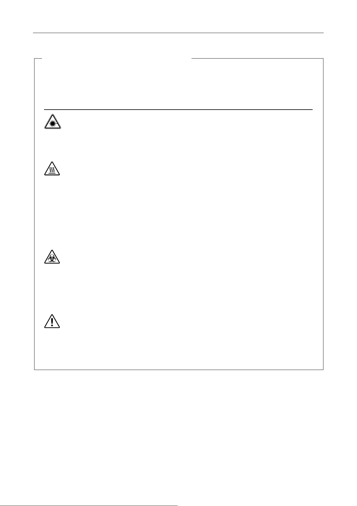
Meaning of the Symbols Used on the Product
The symbols marked on the product indicate the need for caution at all times during use.
Always refer to the instruction manual and read the relevant instructions before manipulating any part
to which the symbol is marked.
Symbol Meaning
Warning label - laser hazard symbol
This symbol is displayed on the laser safety cover or on the stage to warn that the product
emits laser light.
Your eyes or skin may be exposed to the laser light emitted from the objective, resulting in
injury.
Precautions against heat
This symbol, affixed to the top of the dia pillar illuminator, the rear side of the 12V-100W
lamp house, the HG fiber light source, and the rear side of the super-high pressure
mercury lamp (or the xenon lamp) house, calls your attention.
• The lamp and the lamphouse become hot while the lamp is lit and immediately after it
is turned off.
• Do not touch the lamp and the lamphouse while the lamp is on and immediately after it
is turned off to prevent the risk of burns.
• Make sure that the lamp and the lamphouse are sufficiently cool before the lamp
replacement.
Biohazard
This symbol on the upper part of the microscope calls your attention on the following:
• If a specimen is spilled onto the product, it may cause the danger of biohazard.
• To avoid biohazard contamination, do not touch the contaminated portion with your
bare hands.
• Decontaminate the contaminated portion according to the standard procedure of your
facility.
General attention
This symbol is displayed on the top of the protection plate (for nosepiece) appended to the
Ti-E and Ti-E/B and the protection plate (for PFS6 nosepiece) appended to the TI-ND6-PFS
motorized PFS6 nosepiece. It calls your attention on the following:
• To avoid accidents such as finger pinching and exposure to laser radiation, install this
product in the correct position.
3
Page 6
Safety Precautions
WARNING
Use of controls or adjustments or performance of procedures other than those specified in this manual
may result in hazardous radiation exposure.
1. Laser class
This product is a laser apparatus that uses Class 3B lasers (air-cooled Ar lasers, He-Ne lasers,
semiconductor lasers). Accidental exposure of eyes or skin to laser light may result in injury or
other problems. Confirm that there is no one in the area before turning on the lasers. Always wear
laser-protection goggles when using the laser.
2. Laser safety
This product is designed and manufactured in compliance with the Performance Standards for
Light-Emitting Products established by the U.S. FDA and the IEC Laser Product Safety Standard
(IEC 60825-1), except for deviations pursuant to Laser Notice No.50. Those using this laser
product must complete laser safety courses and setup training. Users are requested to take all
appropriate safety measures specified by the preceding standards, in accordance with local laws
and regulations.
The laser safety officer (LSO) must take charge of this laser product and users should follow the
instructions from the LSO.
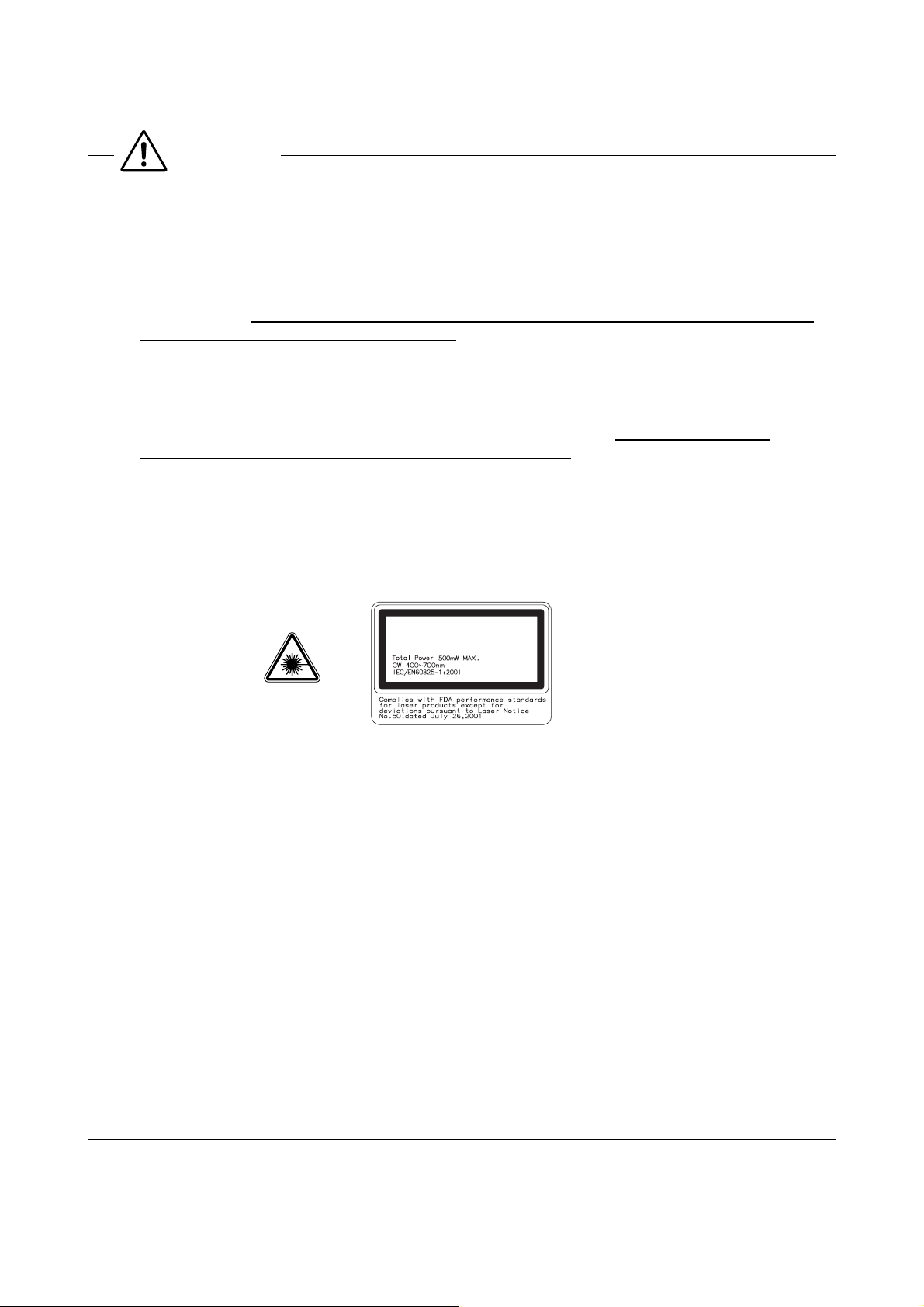
FDA Class 3B Laser Product (Laser Notice No. 50)
IEC Class 3B Laser Product
LASER RADIATION
AVOID EXPOSURE TO BEAM
CLASS 3B LASER PRODUCT
Wavelength: 400 to 700 nm (CW)
Beam divergence: 0.01 to 2.91 rad
Maximum power or energy output: total power 500 mW Max. (CW)
3. Manuals and accessories
All manuals and accessories used in this laser product and provided by the distributor must be
provided to the user.
4. Intended application of the product
This product can be used only for microscopic observations. This product is required to be
attached to the specific Nikon microscope, Ti-E, Ti-E/B, Ti-U, Ti-U/B. Do not use this product for
other purpose.
5. Setting up the product
Setup of this product must be handled by trained service personnel.
This task should not be performed by anyone other than the trained service personnel. If
performed, it may result in improper setup, impairing system performance and exposing the eyes
or skin to the laser light, resulting in injury.
4
Page 7

Safety Precautions
WARNING
6. Prohibition of dismount
This product uses a laser device. Use only in the configuration set up by the Nikon representative.
To ensure safety, never attempt to remove any part of the system. Before beginning operations,
confirm that all of the parts listed below are in place. Removal of any following part during use may
result in unintended exposure of eyes or skin to laser light.
Make sure that all powers to the laser and entire system are turned off when removing an objective
or a filter cube.
Eyepiece tube, nosepiece, objective, TIRF/motorized TIRF illuminator unit, photo activation
illuminator Unit, TIRF-PAU illuminator, filter cube, sage, lamp house, HG fiber adapter,
epi-fl filter turret, 3D-STORM port, TV camera, video camera, or all port caps
7. Do not disassemble.
Disassembling this product may result in electric shock or other hazards.
Never attempt to disassemble any piece of equipment included in this product.
In particular, disassembling any of the components when the laser is on may cause the laser light
to be improperly emitted from this product. If you notice that this product is not functioning properly,
immediately stop use, switch off the power switches to all devices, disconnect the power cables
from the outlets, and contact your nearest Nikon representative.
8. Pre-operation check items
Before using the system, always confirm the followings.
If the following conditions are not satisfied, laser light may be irradiated from openings or reflected
from reflective objects, and unintended exposure of eyes and skin to laser light may result.
1 A cap, 3D-STORM port, a TV camera, or a video camera is attached to each port.
2 An objective or a cap is attached to each socket of the nosepiece.
3 The optical fiber for laser light is securely fixed.
4 The adapter for the HG fiber light source (or the lamphouse) is attached for epi illumination.
And the lamphouse is attached for the dia illumination.
5 The epi-fl filter turret is attached correctly. (Its cover is attached too.)
6 The field diaphragm unit is attached correctly.
7 The laser safety cover is attached on the stage. (The specimen cover is attached for TI-PAU.)
8 There is no mirror or other highly reflective piece of metal in the area surrounding the lens
aperture.
9. Never attempt to look into the laser light.
When the laser is on, a powerful beam of light is emitted above the stage through the objective.
Never look into this beam or reflected beams. When the laser is on, put on laser safety goggles.
To prevent reflection of the laser light emitted from the objectives and resulting inadvertent
exposure of eyes or skin to laser light, never place reflective objects on the stage or in the
diascopic optical path.
TIRF PA TIRF-PA
• NOHD: 2502 m 8.9 m 1904 m for 1x objective.
• NOHD: 642 m 2.2 m 492 m for 4x objective.
• NOHD: 258 m 0.9 m 198 m for 10x objective.
MPE at the cornea for exposure to laser radiation: 1 W/m
MPE of the skin to laser radiation: 2000 W/m
2
(400 nm to 700 nm CW)
2
(400 nm to 700 nm CW)
5
Page 8

Safety Precautions
10. Cautions about heat from the light source
The
Also, the
Follow the cautions below to prevent burn injury and fire.
11. Mercury lamp and xenon lamp
The mercury lamp (or the xenon lamp) used with this product requires special handling. To use the
The hazards described above should not pose any danger as long as you heed all of the warnings
WARNING
symbols affixed to the top of the dia pillar illuminator, the rear side of the lamp house, and
the HG fiber light source indicate that the relevant lamp and its surrounding area become very hot
while the lamp is lit or right after the lamp is turned off.
symbol affixed above the air vent of the HG fiber light source indicates that hot air
blows out of the air vent while the lamp is lit.
• Never touch the lamp, its surrounding parts, and the air vents while the lamp is lit or within
30 minutes after the lamp is turned off.
• Keep hands away from the air vents when the lamp is lit. Do not block the airflow from the air
vents.
• Make sure that the lamp and its surroundings are sufficiently cool before the lamp replacement.
• Do not allow walls, curtains, or papers to contact the product.
• Do not allow cloths, papers, or highly flammable volatile materials, such as gasoline, benzine,
thinner or alcohol, to come near the lamp, its surrounding parts, or the air vents while the lamp is
lit or within 30 minutes after the lamp is turned off.
• Do not draw any power cord on the product body.
system safely and correctly, read the warnings below and be aware of potential dangers. Also,
carefully read the manuals of the light source (HG fiber light source, super-high pressure mercury
lamp power supply, and high-intensity light source) to be used and the manuals published by the
lamp manufacturer if provided, and follow their instructions.
1 The mercury lamp (or the xenon lamp) radiates ultraviolet light that is harmful to the eyes and
skin when the lamp is turned on. Direct viewing of light from these lamps may result in
blindness.
2 Gas is sealed under very high pressure inside the lamps. The pressure increases when the
lamp is on. If the lamp is scratched, dirty, subjected to high external pressure or physical
impact, or used beyond its operational life, the sealed gas may escape or the lamp may burst.
This can result in someone inhaling the gas, injuring themselves on the glass, or other
accidents.
3 When the lamp is on, the lamp and its surroundings become extremely hot. Touching the
lamp with bare hands could result in burns. Flammable materials placed near the lamp could
ignite.
4 Using other than the specified type of lamp could result in an accident, such as a burst.
and cautions in the manuals and use the system only for its intended purpose because safety is a
top priority in the design of Nikon products. However, the hazards described above could lead to
an accident if you fail to heed all of the warnings and cautions in the manuals, if you strike the
system, or if you attempt to disassemble the system. Therefore, always be sure to heed all of the
warnings and cautions.
12. Use the ultraviolet light shield
Do not directly see the light irradiated from the objective. Harmful excitation light will be given out
from the objective depending on the excitation method used. When you see the part around the
objective, be sure to see through the ultraviolet light shield.
6
Page 9

Safety Precautions
13. Notes on handling flammable solvent
The following flammable solvents are used with the product:
Never hold a flame near these solvents. To use solvent, read the instructions provided by the
WARNING
• Immersion oil (Nikon Immersion Oil for oil immersion objectives)
• Absolute alcohol (ethyl alcohol or methyl alcohol for cleaning optical parts)
• Petroleum benzine (for wiping the immersion oil)
• Medical alcohol (for disinfecting the microscopy)
manufacturer and handle the solvent correctly and safely. Note the following precautions to use a
solvent with the product.
• Keep solvent from the heat of the lamp, the lamphouse, and the power supply device.
• Do not bring solvent near the product or its surroundings when turning on/off the power switch or
plugging/unplugging the power cord.
• Be careful not to spill solvent.
7
Page 10

Safety Precautions
1. Precautions on power supply ratings and power cords
Before connecting the power cords to wall outlets, check your power-line ratings to make sure that
2. Precautions on connecting cables
Always switch off the power switches to all devices before connecting or disconnecting cables.
3. Emergency stop
In an emergency, turn off all power switches and unplug the power cords.
4. Do not wet the product.
Do not wet nor spill a liquid on the product to avoid malfunction, over-heating, or electric shock. If a
5. Do not place any object on the product.
To prevent deformation, failure, or malfunction, and to avoid injury, never place any objects (heavy
CAUTION
the input voltage and current capacity requirements of the products are sufficient. Using a wrong
power cord may result in malfunction, failure, or fire. Always use power cords that satisfy local
safety regulations. Always use three-pole grounded outlets.
To prevent wires from breaking, do not pull cables by the sheath; instead, firmly grasp the plug
when connecting or disconnecting a cable.
device is subject to contact with water, immediately switch off the power switch to that device and
wipe off the water with a dry cloth. If water enters a device, immediately suspend use of the
product, unplug the power cord from the outlet, and contact your nearest Nikon representative.
ones in particular) on any part of the system.
8
Page 11

Safety Precautions
6. Notes on Handling the Product
CAUTION
1. Handle the product carefully.
The product is a precision optical instrument. Handle the product with care to avoid a physical
shock or an impact. Optical-fiber cables, in particular, must not be bent or pulled with
excessive force, to prevent failure, malfunction, or wires from breaking.
2. Notes on handling optical parts
Scratches or dirt such as fingerprints on an optical component (such as a lenses or a filter)
will degrade microscope images. Carefully use the optical parts. Do not damage them. If any
part becomes dirty, clean it according to the manuals for respective units.
3. Installation location
To ensure safe and reliable operations, check the following conditions when installing this
product:
• To prevent the product from falling and to avoid eventual failure, install each component of
the product on a level surface.
• Install the product in a clean place with little dust and dirt. Dust or dirt degrades system
performance significantly.
• Use this product at ambient temperatures of between +5 and +35°C and in conditions of
humidity of 60% or less (no condensation). Using the product in hot or humid conditions
may result in condensation or malfunction.
• Make sure that the product is not subject to strong vibrations, which may degrade image
quality. Consult with Nikon representatives about preventive measures you may take when
the product is installed.
• To prevent degradation, malfunction, or failure of the laser and the PC, always use power
supply that is free from electric noise or sudden voltage fluctuations.
• To prevent failure, do not block or place any obstacles near the cooling fans of the
controller and the laser. When the product is installed near a wall, be sure to provide a
clearance of 15 cm or more between the wall and the product.
• Install the product at a place where all the power cables can be pulled out easily in an
emergency.
4. Cleaning
Use a dry and soft cloth to clean painted, plastic, and printed parts. If necessary, wipe these
parts with a cloth moistened with diluted neutral detergent, then wipe off the moisture with a
soft and dry cloth. To prevent discoloration or deformation of painted or plastic parts or
removal of the printed letters/figures, do not use organic solvents such as paint thinner or
alcohol.
5. Other categories
Be sure to follow the instructions specified in this manual. Failure to do so may result in
impaired performance, malfunction, failure, or unexpected hazards.
9
Page 12

How to Use This Manual
Configuration of This Manual
This setup manual is made up of two parts. Refer to the part which deals with the product you are setting up.
• Part 1 For Setting Up TI-TIRF, TI-TIRF-E, or TI-PAU
• Part 2 For Setting Up TI-TIRF-PAU and LU4-B5
10
Page 13

Part 1
For Setting Up TI-TIRF, TI-TIRF-E, or TI-PAU
Series
Setup Manual
<For Authorized Nikon Personnel>
Page 14

Page 15

Contents
1. System Configurations and Part Names............................................................................................1-4
1.1 Overview ........................................................................................................................................ 1-4
1.1.1 TIRF Illuminator Unit and Ti-U System Overview .............................................................. 1-4
1.1.2 Motorized TIRF Illuminator Unit and Ti-E System Overview ............................................. 1-8
1.1.3 Motorized TIRF Illuminator Unit, LU4A, N-STORM, and Ti-E System Overview............. 1-12
1.1.4 TI-PAU Photo Activation Illuminator Unit and Ti-U System Overview.............................. 1-14
1.2 Optical Paths of Lasers ................................................................................................................ 1-18
1.2.1 Laser Unit......................................................................................................................... 1-18
1.2.2 Microscope Part (TIRF Illuminator Unit and Ti-U System)............................................... 1-19
1.2.3 Microscope Part (Motorized TIRF Illuminator Unit and Ti-E System) .............................. 1-20
1.2.4 Microscope Part (Motorized TIRF Illuminator Unit, LU4A, N-STORM, and Ti-E System)1-21
1.2.5 Microscope Part (Photo Activation Illuminator Unit and Ti-U System)............................. 1-22
1.3 Safety Labels and Openings ........................................................................................................ 1-23
1.3.1 Ti-U Microscope Body (with the TIRF Illuminator Unit).................................................... 1-24
1.3.2 Ti-E Microscope Body (with the Motorized TIRF Illuminator Unit)................................... 1-25
1.3.3 Ti-U Microscope Body (with the TI-PAU Photo Activation Illuminator Unit)........................ 1-26
1.3.4 C-LU2 Two-laser Unit....................................................................................................... 1-27
1.3.5 C-LU3 Three-laser Unit.................................................................................................... 1-28
1.3.6 C-LU3EX Three-laser Unit EX ......................................................................................... 1-29
1.3.7 LU4A Four-laser Module A............................................................................................... 1-30
1.3.8 LU-LR Four-laser PS Rack .............................................................................................. 1-31
1.3.9 TI-LUSU Shutter Unit....................................................................................................... 1-32
1.3.10 TI-LU4SU Shutter Unit LU4 ............................................................................................. 1-34
1.3.11 TI-TIRF TIRF Illuminator Unit........................................................................................... 1-36
1.3.12 TI-TIRF-E Motorized TIRF Illuminator Unit ― For Normal Microscopy
(Except N-STORM).......................................................................................................... 1-37
1.3.13 TI-TIRF-E Motorized TIRF Illuminator Unit ― For N-STORM Microscopy...................... 1-38
1.3.14 TI-PAU Photo Activation Illuminator Unit ......................................................................... 1-39
1.4 Name of Each Part....................................................................................................................... 1-40
1.4.1 TIRF Illuminator Unit and Ti-U System ............................................................................ 1-40
1.4.2 Motorized TIRF Illuminator Unit and Ti-E System............................................................ 1-45
1.4.3 Motorized TIRF Illuminator Unit, LU4A, N-STORM and Ti-E System.............................. 1-49
1.4.4 TI-PAU Photo Activation Illuminator Unit and Ti-U System.............................................. 1-54
1.4.5 Laser Unit......................................................................................................................... 1-58
1.4.6 Laser Safety Kit................................................................................................................1-62
1.4.7 Related Product ............................................................................................................... 1-64
2. Preparations........................................................................................................................................ 1-67
2.1 Check Items and Tools ................................................................................................................. 1-67
2.1.1 Required Items................................................................................................................. 1-67
2.1.2 Tools ................................................................................................................................. 1-68
2.2 Overview of Setup Procedure ...................................................................................................... 1-69
3. Setting Up the PC and Operation Software ..................................................................................... 1-70
1-1
Page 16

Contents
4. Setting Up the Microscope ................................................................................................................ 1-71
4.1 List of Parts .................................................................................................................................. 1-71
4.2 Setup Procedure .......................................................................................................................... 1-74
4.2.1 Assembling Each Part and Attaching Them to the Microscope....................................... 1-74
4.2.2 Attaching the N-STORM Kit............................................................................................. 1-85
4.2.3 Attaching the Laser Safety Kit.......................................................................................... 1-87
4.2.4 Attaching the Stage Up Kit............................................................................................... 1-89
4.2.5 Attaching the Back Port Unit............................................................................................ 1-92
5. Laser Unit............................................................................................................................................ 1-93
5.1 Overview of the Laser Units......................................................................................................... 1-94
5.1.1 AOM Controller (Optional) ............................................................................................. 1-100
5.1.2 LU-LR Four-laser PS Rack ............................................................................................ 1-101
5.2 C-LU2 Two-laser Unit, and C-LU3 Three-laser Unit .................................................................. 1-103
5.2.1 Preparation.....................................................................................................................1-103
5.2.2 Laser Installation............................................................................................................ 1-104
5.2.3 Laser Rough Adjustment................................................................................................ 1-106
5.2.4 Final Adjustment for the Ar Laser Light with the Optical Fiber....................................... 1-113
5.2.5 Final Adjustment for the He-Ne Laser Light and 405 Laser Light
with the Optical Fiber ..................................................................................................... 1-119
5.2.6 Attaching the Sheet Metal Covers ................................................................................. 1-121
5.3 C-LU3EX Three-laser Unit EX ................................................................................................... 1-122
5.3.1 Preparation.....................................................................................................................1-123
5.3.2 Laser Installation............................................................................................................ 1-125
5.3.3 Laser Rough Adjustment 1............................................................................................. 1-128
5.3.4 Laser Rough Adjustment 2............................................................................................. 1-139
5.3.5 Final Adjustment for the Ar Laser Light with the Optical Fiber....................................... 1-146
5.3.6 Final Adjustment for the He-Ne Laser Light and 405 Laser Light
with the Optical Fiber ..................................................................................................... 1-152
5.3.7 Adjusting the AOM Controller (When the AOM Unit Used Only) ................................... 1-154
5.3.8 Attaching the Sheet Metal Cover ................................................................................... 1-155
5.4 LU4A Four-laser Module A ......................................................................................................... 1-156
5.4.1 Preparation.....................................................................................................................1-157
5.4.2 Laser Installation............................................................................................................ 1-161
5.4.3 Laser Rough Adjustment 1............................................................................................. 1-171
5.4.4 Laser Rough Adjustment 2............................................................................................. 1-183
5.4.5 Final Adjustment for the Ar Laser Light with the Optical Fiber....................................... 1-189
5.4.6 Final Adjustment for Other Laser Light with the Optical Fiber ....................................... 1-194
5.4.7 Removing the AOTF Driver Remote Controller ............................................................. 1-196
5.4.8 Attaching the Sheet Metal Cover ................................................................................... 1-197
5.5 Setting Up the LU-LR Four-laser PS Rack ................................................................................ 1-198
5.5.1 System Description........................................................................................................ 1-198
5.5.2 Mounting Laser Power Supply....................................................................................... 1-201
5.5.3 Details on Mounting Laser Supply................................................................................. 1-207
1-2
Page 17

Contents
6. Connection between the Laser Unit and the Microscope ............................................................ 1-213
6.1 Setting and Connecting the TI-LUSU Shutter Unit..................................................................... 1-213
6.1.1 Control System Selection............................................................................................... 1-214
6.1.2 Control Mode of the Shutter Unit ................................................................................... 1-214
6.1.3 Setting and Connecting the TI-LU4SU Shutter Unit LU4............................................... 1-215
6.1.4 DIP Switch Settings ....................................................................................................... 1-217
6.1.5 Communications Commands......................................................................................... 1-219
6.2 Attaching the Optical Fiber to the Light Source ......................................................................... 1-222
6.3 Replacement of Optical Path Switch Mirror ............................................................................... 1-224
6.4 Installing the N-STORM Kit........................................................................................................ 1-226
7. Confirmation and Check Sheet ....................................................................................................... 1-228
7.1 Checking Procedure................................................................................................................... 1-228
7.2 Check Sheet............................................................................................................................... 1-229
8. Specifications and Performance..................................................................................................... 1-231
8.1 Overall Configuration ................................................................................................................. 1-231
8.1.1 TIRF Illuminator Unit / Motorized TIRF Illuminator Unit― Configuration for Normal
Microscopy (Except N-STORM)..................................................................................... 1-231
8.1.2 Motorized TIRF Illuminator Unit ― Configuration for N-STORM................................... 1-232
8.1.3 Photo Activation Illuminator Unit .................................................................................... 1-234
8.1.4 Mountable lasers............................................................................................................ 1-235
8.1.5 TI-LUSU Shutter Unit..................................................................................................... 1-238
8.1.6 AC Adapter for the TI-LUSU Shutter Unit ...................................................................... 1-238
8.1.7 Power Cord for the AC Adapter of the TI-LUSU Shutter Unit ........................................ 1-238
8.2 Environmental Conditions .......................................................................................................... 1-239
8.2.1 Normal Microscopy (Except N-STORM)........................................................................ 1-239
8.2.2 N-STORM ...................................................................................................................... 1-239
8.3 Safety Standards Compliance.................................................................................................... 1-240
8.3.1 Normal Microscopy (Except N-STORM)........................................................................ 1-240
8.3.2 N-STORM ...................................................................................................................... 1-241
1-3
Page 18
1
System Configurations and Part Names
1.1 Overview
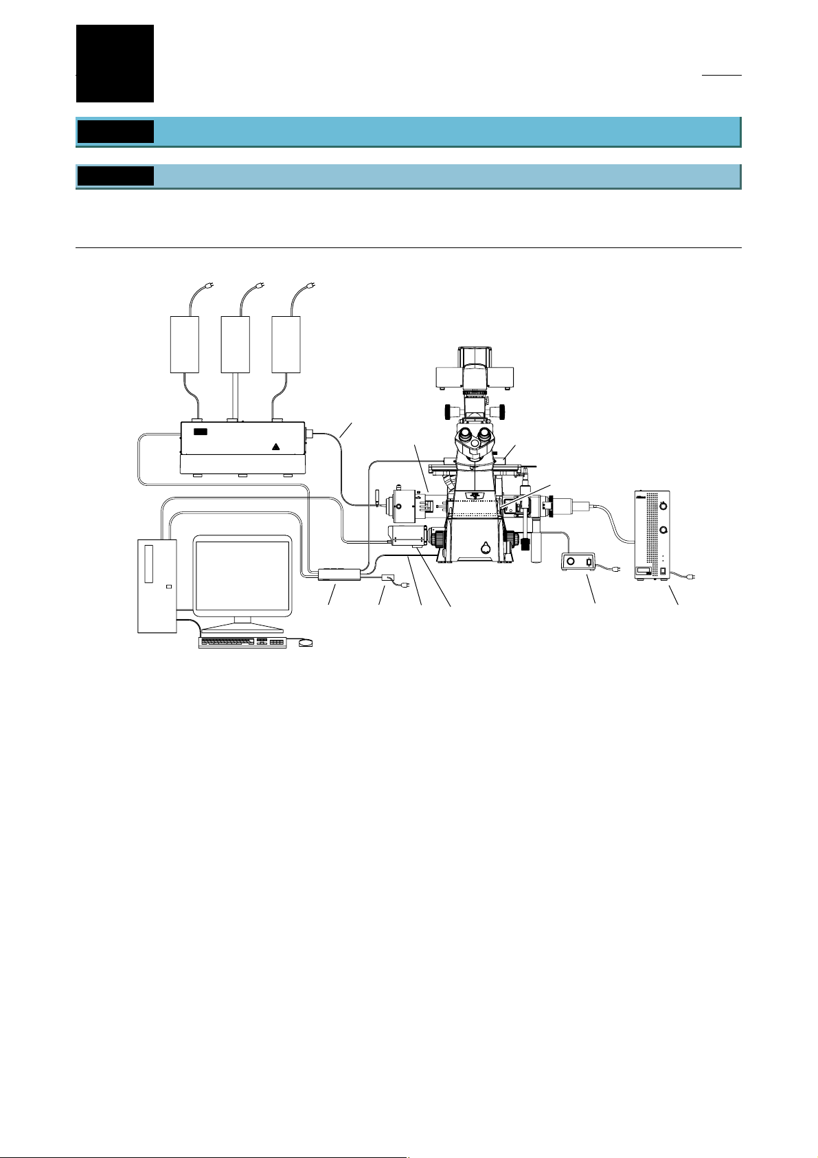
1.1.1 TIRF Illuminator Unit and Ti-U System Overview
TIRF illuminator unit and Ti-U system overview (front view):
When used in combination with two-laser or three-laser unit
(Standard configuration to use the TIRF illuminator unit)
(1)
(4)
(2)
(10)
(12)
(3)
* For details, see Section 8.1, “Overall Configuration,” in Chapter 8, “Specifications and Performance.”
(5)
(6)
(1) Power supply devices for the laser devices
(2) Laser unit (C-LU2, C-LU3, C-LU3EX)
(3) PC
(4) Optical fiber
(5) TI-LUSU shutter unit
(6) AC adapter for the shutter unit
(7) TV camera (video camera)
(8) TI-FLC epi-fl filter turret
(9) Power supply device for the diascopic illumination
(10) TIRF illuminator unit
(11) HG fiber light source
(12) Laser safety cover
(13) Interlock cable
CLASS 3B
–
LASER RADIATION WHEN OPEN
AVOID EXPOSURE TO THE BEAM
CAUTION
(13)
Figure 1.1-1
(7)
(8)
(9)
(11)
1-4
Page 19
Chapter 1 System Configurations and Part Names
1.1 Overview
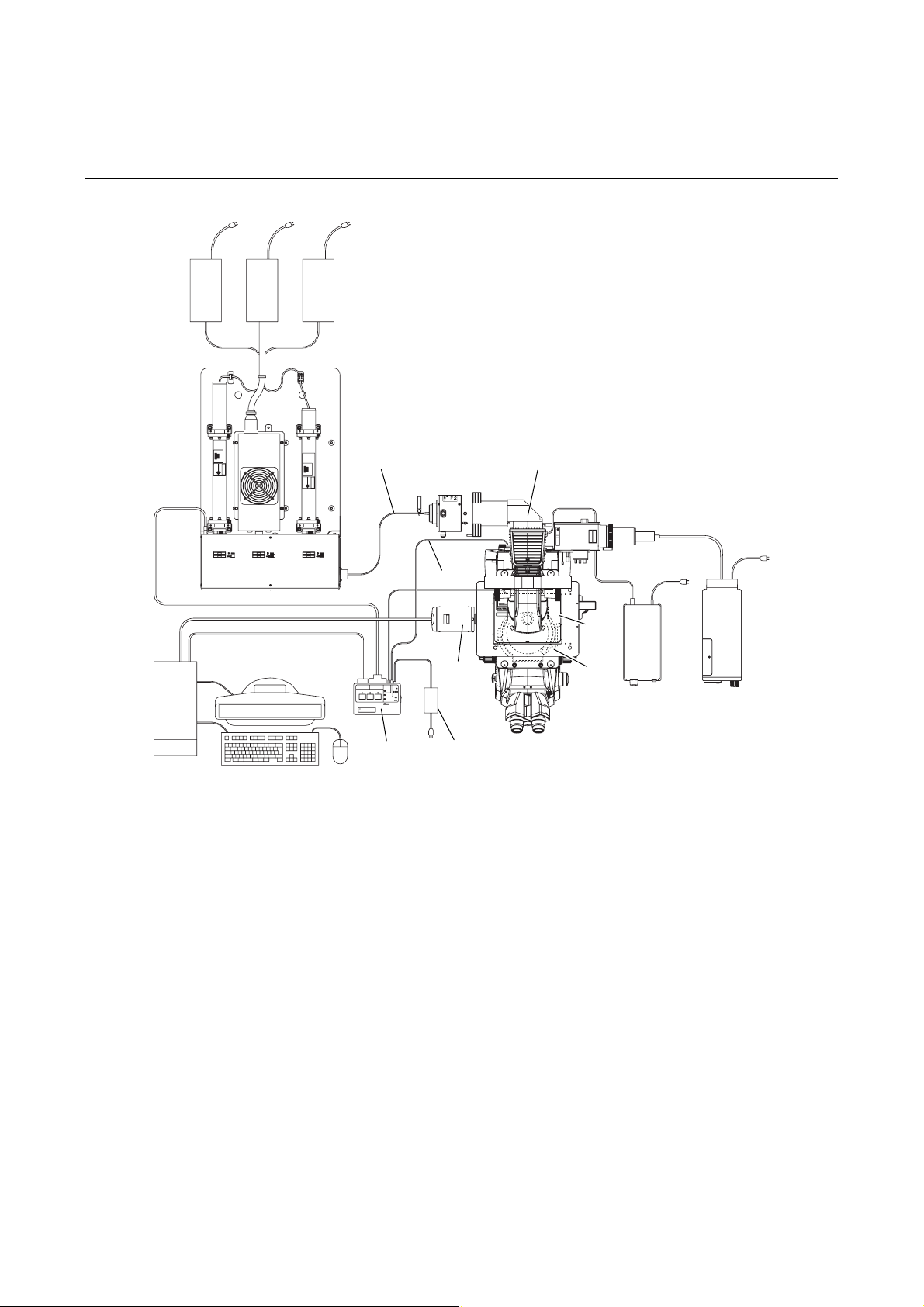
TIRF illuminator unit and Ti-U system overview (top view):
When used in combination with two-laser or three-laser unit
(1)
(2)
(4)
CLASS 3B
–
LASER RADIATION WHEN OPEN
AVOID EXPOSURE TO THE BEAM
CAUTION
INPUT
RS-232C LASER UNIT
12V
SAFETY
1A
LASER SHUTTER
COVER
CLOSE
BINO
CLOSE
POWER
(3)
Exclusive use for TI-TIRF system
Don't use this unit with other systems.
TI-LUSU
(5)
* For details, see Section 8.1, “Overall Configuration,” in Chapter 8, “Specifications and Performance.”
(1) Power supply devices for the laser devices
(2) Laser unit (C-LU2, C-LU3, C-LU3EX)
(3) PC
(4) Optical fiber
(5) TI-LUSU shutter unit
(6) AC adapter for the shutter unit
(7) TV camera (video camera)
(8) TI-FLC epi-fl filter turret
(9) Power supply device for the diascopic illumination
(10) TIRF illuminator unit
(11) HG fiber light source
(12) Laser safety cover
(13) Interlock cable
(13)
(7)
(6)
Figure 1.1-2
(10)
LASERSTRAHLUNG
CLASS 3B
–
–
KLASSE 3B,
WENN ABDECKUNG GEÖFFNET
NICHT DEM STRAHL AUSSETZEN
LASER RADIATION WHEN OPEN
AVOID EXPOSURE TO THE BEAM
VORSICHT
CAUTION
SER RADIATIO
OID EXPOSU
CLASS 3B LASE
AVOID EXPOSURE
LASER LIGHT IS EMITTE
FROM
OBJECTIVE APERT
(12)
(11)
(9)
(8)
1-5
Page 20
Chapter 1 System Configurations and Part Names
(12)
1.1 Overview
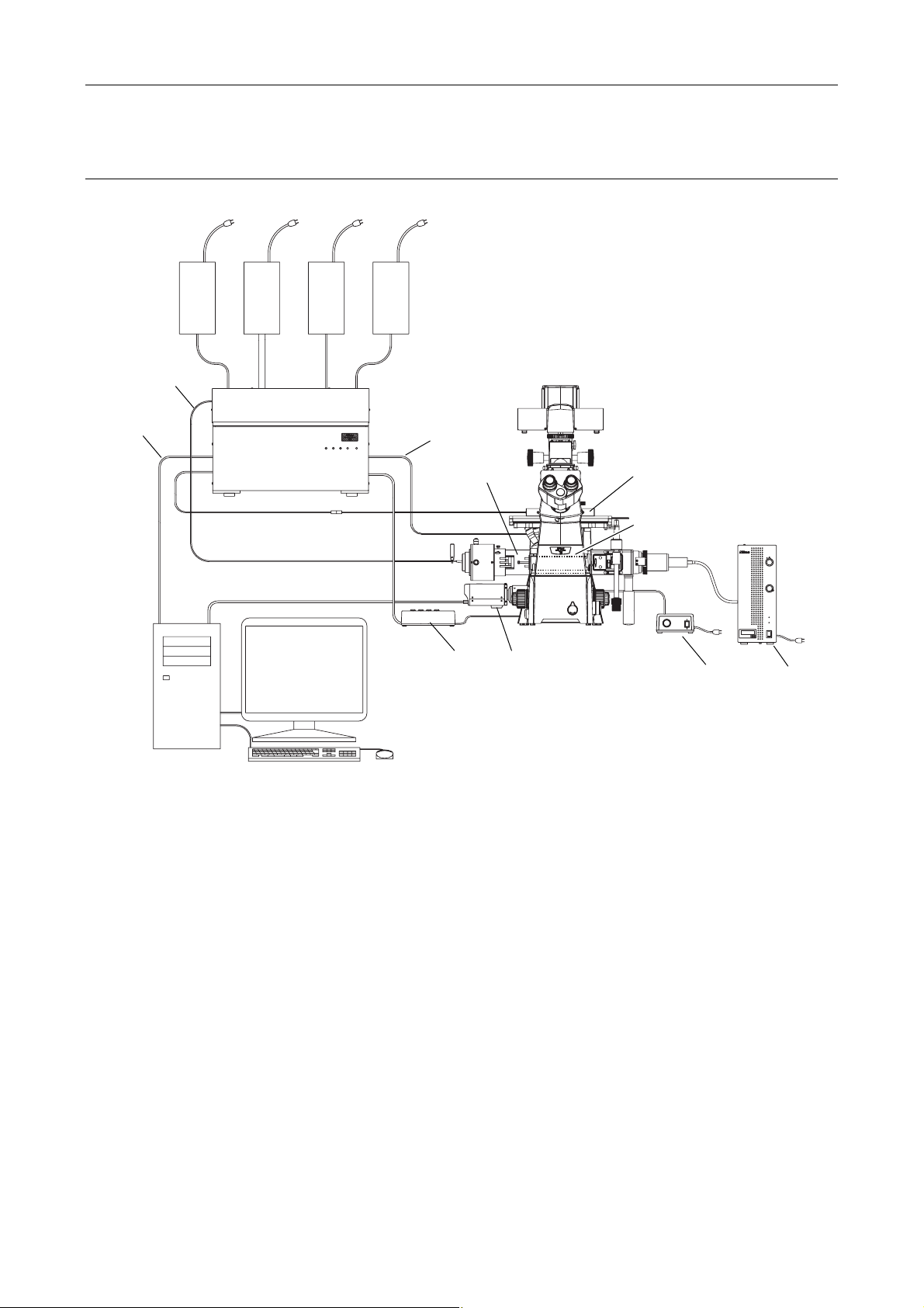
TIRF illuminator unit and Ti-U system overview (front view):
When used with four-laser module A
(Standard configuration to use the TIRF illuminator unit)
(1)
(4)
(2)
(13)
POWER
L4
L3
L1
L2
(3)
* For details, see Section 8.1, “Overall Configuration,” in Chapter 8, “Specifications and Performance.”
(1) Power supply devices for the laser devices
(2) Laser unit (LU4A)
(3) PC
(4) Optical fiber
(5) TI-LU4SU shutter unit LU4
(6) TV camera (video camera)
(7) TI-FLC epi-fl filter turret
(8) Power supply device for the diascopic illumination
(9) TIRF illuminator unit
(10) HG fiber light source
(11) Laser safety cover
(12) Interlock cable
(13) USB cable
(9) (11)
CLASS 3B
–
CAUTION
LASER RADIATION WHEN OPEN
AVOID EXPOSURE TO THE BEAM
(5)
Figure 1.1-3
(7)
(6)
(8) (10)
1-6
Page 21
Chapter 1 System Configurations and Part Names
(12)
1.1 Overview
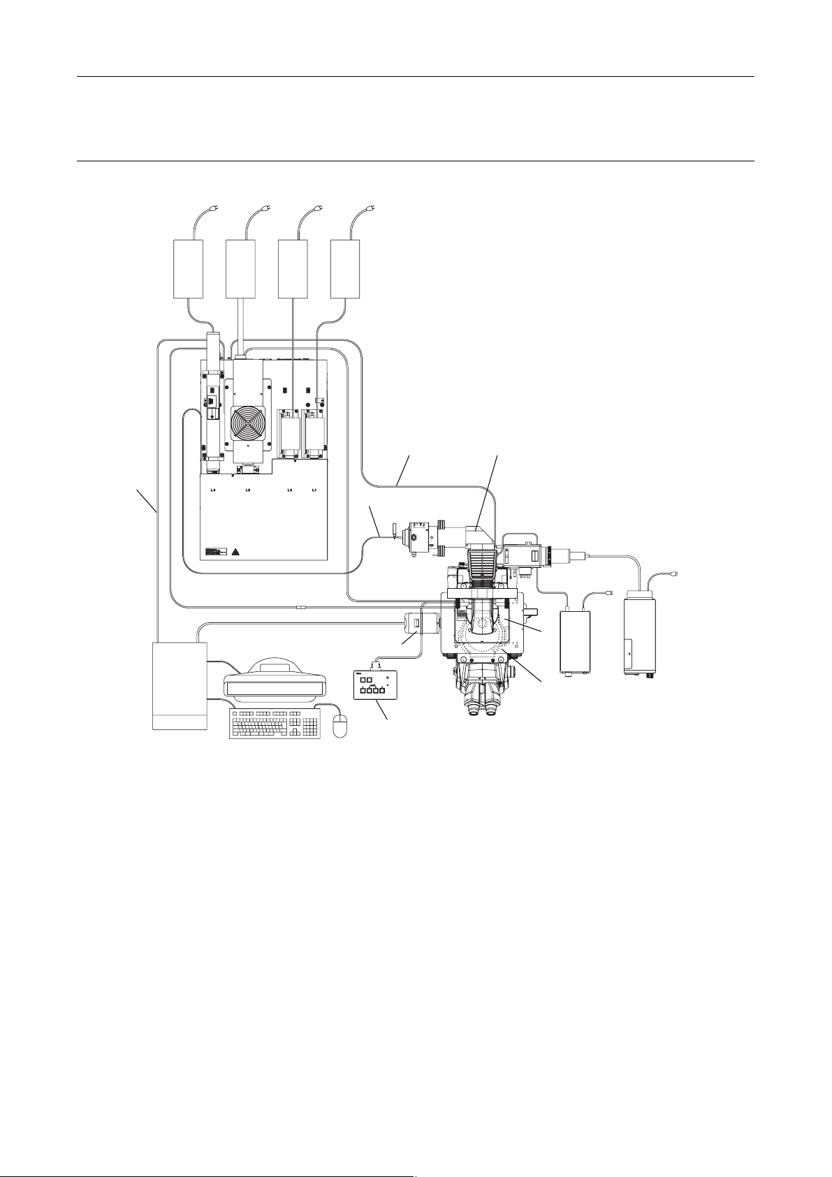
TIRF illuminator unit and Ti-U system overview (top view):
When used with four-laser module A
(Standard configuration to use the TIRF illuminator unit)
(1)
(2)
(9)
(13)
(4)
(3)
TI-LU4SU
* For details, see Section 8.1, “Overall Configuration,” in Chapter 8, “Specifications and Performance.”
(1) Power supply devices for the laser devices
(2) Laser unit (LU4A)
(3) PC
(4) Optical fiber
(5) TI-LU4SU shutter unit LU4
(6) TV camera (video camera)
(7) TI-FLC epi-fl filter turret
(8) Power supply device for the diascopic illumination
(9) TIRF illuminator unit
(10) HG fiber light source
(11) Laser safety cover
(12) Interlock cable
(13) USB cable
CLASS 3B
–
LASER RADIATION WHEN OPEN
AVOID EXPOSURE TO THE BEAM
CAUTION
(6)
LASER
EMISSION
POWER
(5)
Figure 1.1-4
LASERSTRAHLUNG
CLASS 3B
–
–
CAUTION
KLASSE 3B,
WENN ABDECKUNG GEÖFFNET
NICHT DEM STRAHL AUSSETZEN
LASER RADIATION WHEN OPEN
AVOID EXPOSURE TO THE BEAM
VORSICHT
SER RADIATIO
OID EXPOSU
CLASS 3B LASE
AVOID EXPOSURE
LASER LIGHT IS EMITTE
OBJECTIVE APERT
FROM
(8)
(11)
(10)
(7)
1-7
Page 22
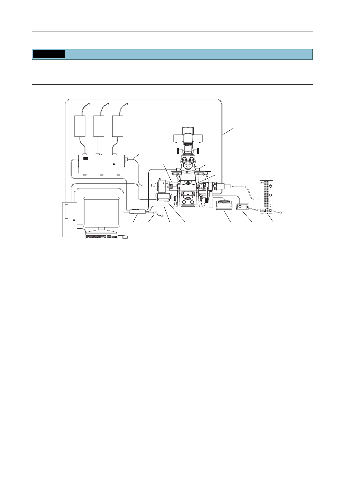
Chapter 1 System Configurations and Part Names
1.1 Overview
1.1.2 Motorized TIRF Illuminator Unit and Ti-E System Overview
Motorized TIRF illuminator unit and Ti-E system overview (front view):
When used in combination with two-laser or three-laser unit
(Standard configuration to use the motorized TIRF illuminator unit)
(1)
(4)
(2)
CLASS 3B
CLASS 3B
–
–
LASER RADIATION WHEN OPEN
AVOID EXPOSURE TO THE BEAM
CAUTION
LASER RADIATION WHEN OPEN
AVOID EXPOSURE TO THE BEAM
CAUTION
(6) (9) (12)
(3)
(5) (7)
* For details, see Section 8.1, “Overall Configuration,” in Chapter 8, “Specifications and Performance.”
(1) Power supply devices for the laser devices
(2) Laser unit (C-LU2, C-LU3, C-LU3EX)
(3) PC
(4) Optical fiber
(5) TI-LUSU shutter unit
(6) AC adapter for the shutter unit
(7) TV camera (video camera)
(8) TI-FLC-E/HQ motor epi-fl filter turret
(9) Power supply device for the diascopic illumination
(10) Hub controller A (with AC adapter)
(11) Motorized TIRF illuminator unit
(12) HG fiber light source
(13) Remote control pad
(14) Laser safety cover
(15) Interlock cable
(16) USB cable
(11)
(15)
Figure 1.1-5
(16)
(14)
(8)
(13)
1-8
Page 23

Chapter 1 System Configurations and Part Names
1.1 Overview
Motorized TIRF illuminator unit and Ti-E system overview (top view):
When used in combination with two-laser or three-laser unit
(Standard configuration to use the motorized TIRF illuminator unit)
(1)
(2)
(3)
(4)
RS-232C LASER UNIT
LASER SHUTTER
Exclusive use for TI-TIRF system
Don't use this unit with other systems.
(5)
SAFETY
COVER
CLOSE
BINO
CLOSE
POWER
TI-LUSU
(15)
INPUT
12V
1A
(11)
CLASS 3B
CLASS 3B
–
–
CAUTION
LASER RADIATION WHEN OPEN
AVOID EXPOSURE TO THE BEAM
LASER RADIATION WHEN OPEN
AVOID EXPOSURE TO THE BEAM
CAUTION
(14)
(7)
(8)
(6)
Figure 1.1-6
(16)
(10)
LASERSTRAHLUNG
LASERSTRAHLUNG
CLASS 3B
CLASS 3B
–
–
–
–
CAUTION
LASER RADIATION WHEN OPEN
AVOID EXPOSURE TO THE BEAM
VORSICHT
KLASSE 3B,
WENN ABDECKUNG GEÖFFNET
NICHT DEM STRAHL AUSSETZEN
KLASSE 3B,
WENN ABDECKUNG GEÖFFNET
NICHT DEM STRAHL AUSSETZEN
LASER RADIATION WHEN OPEN
AVOID EXPOSURE TO THE BEAM
VORSICHT
CAUTION
SER RADIATIO
SER RADIATIO
OID EXPOSU
OID EXPOSU
CLASS 3B LASE
CLASS 3B LASE
AVOID EXPOSURE
AVOID EXPOSURE
LASER LIGHT IS EMITTE
LASER LIGHT IS EMITTE
OBJECTIVE APERT
FROM
OBJECTIVE APERT
FROM
(12)
(9)
(13)
* For details, see Section 8.1, “Overall Configuration,” in Chapter 8, “Specifications and Performance.”
(1) Power supply devices for the laser devices
(2) Laser unit (C-LU2, C-LU3, C-LU3EX)
(3) PC
(4) Optical fiber
(5) TI-LUSU shutter unit
(6) AC adapter for the shutter unit
(7) TV camera (video camera)
(8) TI-FLC-E/HQ motor epi-fl filter turret
(9) Power supply device for the diascopic illumination
(10) Hub controller A (with AC adapter)
(11) Motorized TIRF illuminator unit
(12) HG fiber light source
(13) Remote control pad
(14) Laser safety cover
(15) Interlock cable
(16) USB cable
1-9
Page 24

Chapter 1 System Configurations and Part Names
1.1 Overview
Motorized TIRF illuminator unit and Ti-E system overview (front view):
When used with four-laser module A
(Standard configuration to use the motorized TIRF illuminator unit)
(1)
(4)
(2)
(15)
(15)
POWER
L4
L3
L1
L2
(14)
(10) (13)
(7)
(5)
(3)
* For details, see Section 8.1, “Overall Configuration,” in Chapter 8, “Specifications and Performance.”
(1) Power supply devices for the laser devices
(2) Laser unit (LU4A)
(3) PC
(4) Optical fiber
(5) TI-LU4SU shutter unit LU4
(6) TV camera (video camera)
(7) TI-FLC-E/HQ motor epi-fl filter turret
(8) Power supply device for the diascopic illumination
(9) Hub controller A (with AC adapter)
(10) Motorized TIRF illuminator unit
(11) HG fiber light source
(12) Remote control pad
(13) Laser safety cover
(14) Interlock cable
(15) USB cable
(6) (8) (11)
(12)
Figure 1.1-7
1-10
Page 25
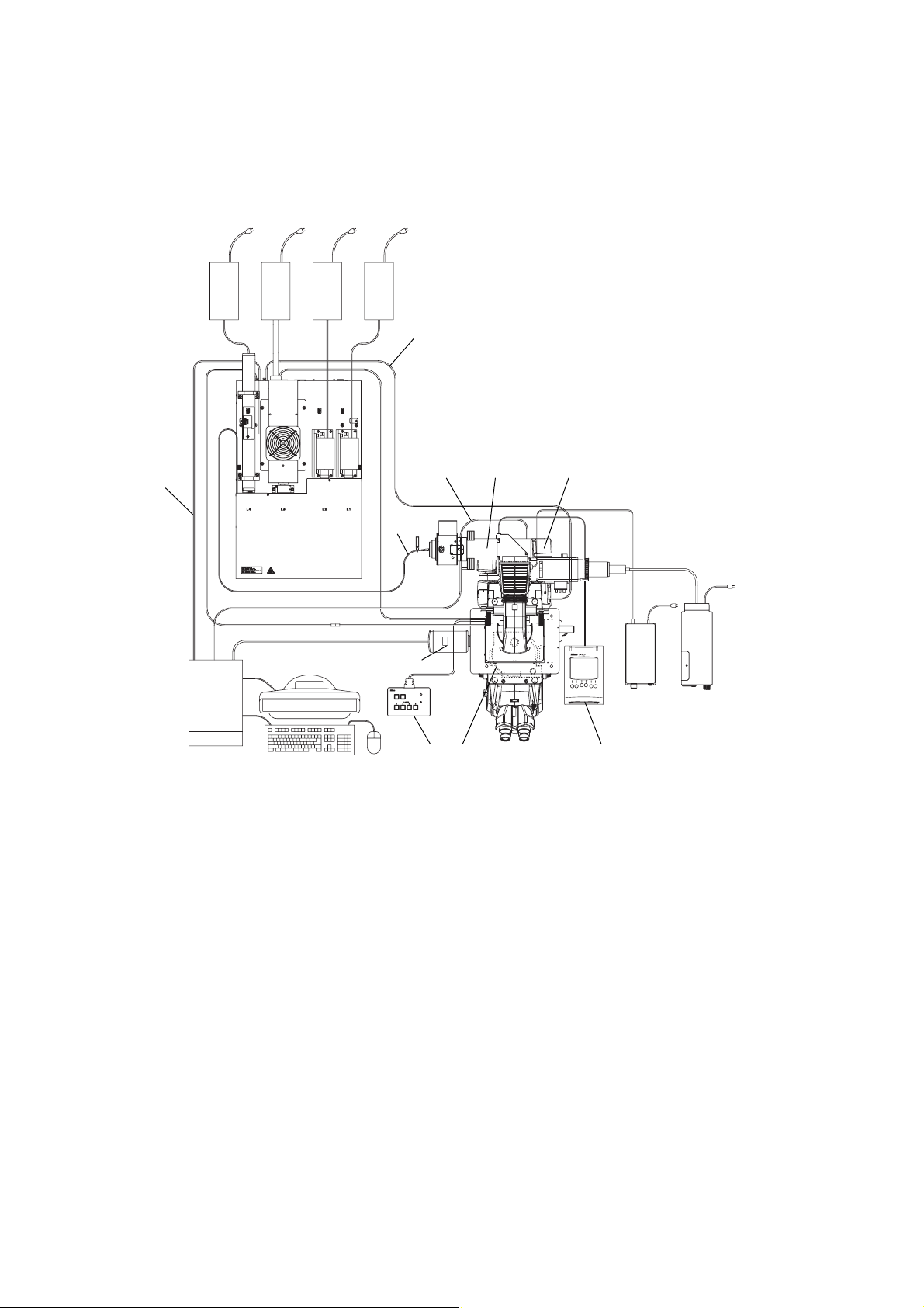
Chapter 1 System Configurations and Part Names
(9)
1.1 Overview
Motorized TIRF illuminator unit and Ti-E system overview (top view):
When used in combination with four-laser module A
(Standard configuration to use the motorized TIRF illuminator unit)
(1)
(14)
(2)
(15)
(4)
CLASS 3B
CLASS 3B
–
–
CAUTION
LASER RADIATION WHEN OPEN
AVOID EXPOSURE TO THE BEAM
LASER RADIATION WHEN OPEN
AVOID EXPOSURE TO THE BEAM
CAUTION
(6)
(3)
TI-LU4SU
* For details, see Section 8.1, “Overall Configuration,” in Chapter 8, “Specifications and Performance.”
(1) Power supply devices for the laser devices
(2) Laser unit (LU4A)
(3) PC
(4) Optical fiber
(5) TI-LU4SU shutter unit LU4
(6) TV camera (video camera)
(7) TI-FLC-E/HQ motor epi-fl filter turret
(8) Power supply device for the diascopic illumination
(9) Hub controller A (with AC adapter)
(10) Motorized TIRF illuminator unit
(11) HG fiber light source
(12) Remote control pad
(13) Laser safety cover
(14) Interlock cable
(15) USB cable
(10)
(7)
LASER
EMISSION
POWER
(5)
(15)
Figure 1.1-8
(12)
(8)
(11)
1-11
Page 26
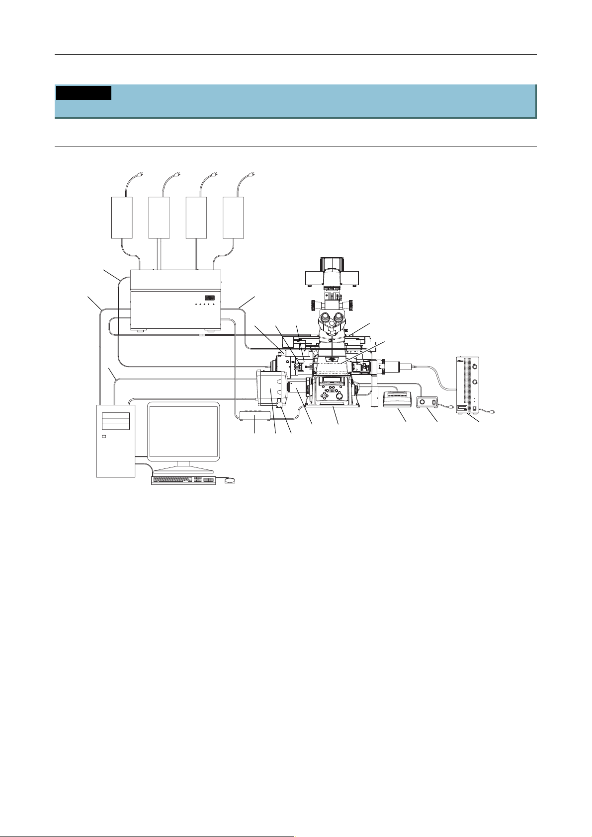
Chapter 1 System Configurations and Part Names
1.1 Overview
1.1.3 Motorized TIRF Illuminator Unit, LU4A, N-STORM, and Ti-E System
Overview
Motorized TIRF illuminator unit, LU4A, N-STORM, and Ti-E system overview (front view)
(Standard configuration to use the Motorized TIRF illuminator unit)
(1)
(4)
(2)
(15)
POWER
L4
L3
L1
L2
(14)
(10)
(20)(19)
(13)
(7)
(15)
(3)
* For details, see Section 8.1, “Overall Configuration,” in Chapter 8, “Specifications and Performance.”
(1) Power supply devices for the laser devices
(2) Laser unit (LU4A)
(3) PC
(4) Optical fiber
(5) TI-LU4SU shutter unit LU4
(6) EM-CCD camera
(7) TI-FLC-E/HQ motor epi-fl filter turret
(8) Power supply device for the diascopic
illumination
(9) Hub controller A (with AC adapter)
(10) Motorized TIRF illuminator unit
(11) HG fiber light source
(12) Remote control pad
(13) Laser safety cover
(6)
(5)
Figure 1.1-9
(17)
(16) (18)
(12)
(8) (11)
(14) Interlock cable
(15) USB cable
(16) 3D-STORM port
(17) DSC support columns (2 pieces)
(18) Ti-E fixing plate
(19) STORM slider
(20) Lambda plate slider
(21) 405-nm laser adapter with ND
(See Figure 1.1-10 for the location.)
(22) 457-nm laser adapter with ND
(See Figure 1.1-10 for the location.)
(23) 561-nm laser adapter with ND
(See Figure 1.1-10 for the location.)
1-12
Page 27
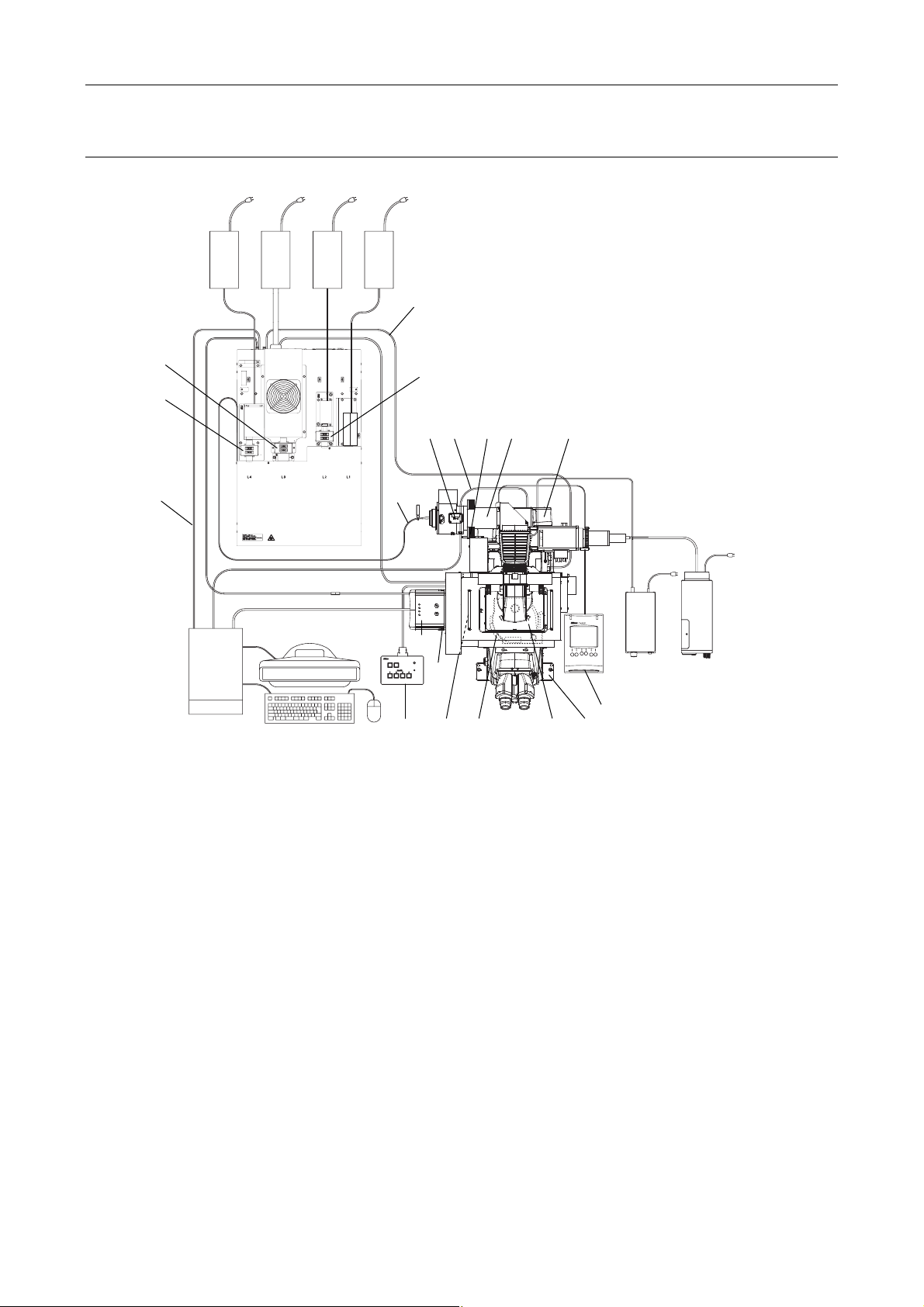
Chapter 1 System Configurations and Part Names
(9)
1.1 Overview
Motorized TIRF illuminator unit, LU4A, N-STORM, and Ti-E system overview (top view)
(Standard configuration to use the Motorized TIRF illuminator unit)
(1)
(14)
(22)
(2)
transportation.
Fix the laser unit with
four blocks during
(23)
(15)
(3)
* For details, see Section 8.1, “Overall Configuration,” in Chapter 8, “Specifications and Performance.”
(1) Power supply devices for the laser devices
(2) Laser unit (LU4A)
(3) PC
(4) Optical fiber
(5) TI-LU4SU shutter unit LU4
(6) EM-CCD camera
(7) TI-FLC-E/HQ motor epi-fl filter turret
(8) Power supply device for the diascopic
illumination
(9) Hub controller A (with AC adapter)
(10) Motorized TIRF illuminator unit
(11) HG fiber light source
(12) Remote control pad
(21)
(4)
CLASS 3B
CLASS 3B
–
–
CAUTION
LASER RADIATION WHEN OPEN
AVOID EXPOSURE TO THE BEAM
LASER RADIATION WHEN OPEN
AVOID EXPOSURE TO THE BEAM
CAUTION
(6)
TI-LU4SU
LASER
EMISSION
POWER
(17)
(5)
(16) (13) (18)
Figure 1.1-10
(15)
(20)(19)
(10)
(11)
(8)
(12)
(7)
(13) Laser safety cover
(14) Interlock cable
(15) USB cable
(16) 3D-STORM port
(17) DSC support columns (2 pieces)
(18) Ti-E fixing plate
(19) STORM slider
(20) Lambda plate slider
(21) 405-nm laser adapter with ND
(22) 457-nm laser adapter with ND
(23) 561-nm laser adapter with ND
1-13
Page 28
Chapter 1 System Configurations and Part Names
1.1 Overview
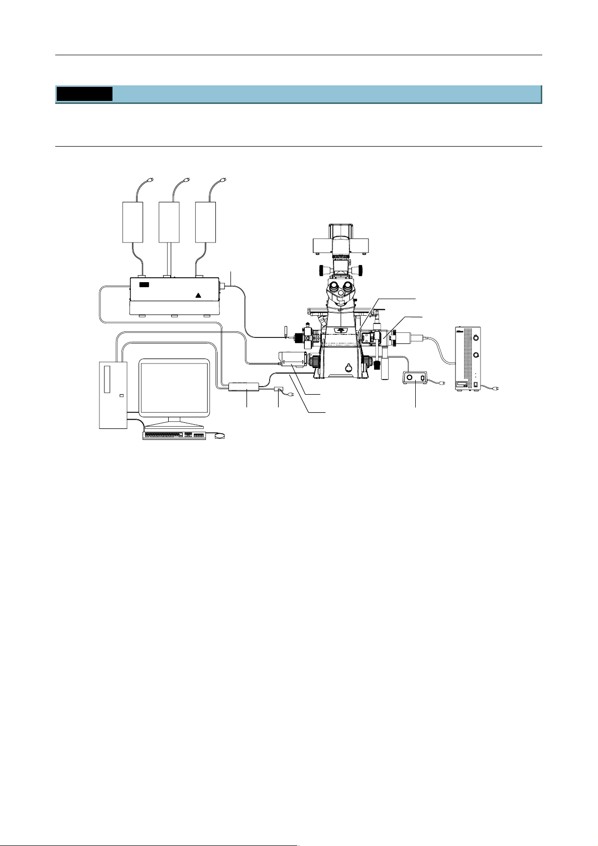
1.1.4 TI-PAU Photo Activation Illuminator Unit and Ti-U System Overview
Photo activation illuminator unit and Ti-U (front view):
When used in combination with two-laser or three-laser unit
(Standard configuration to use the photo activation illuminator unit)
(1)
(4)
(2)
(3)
* For details, see Section 8.1, “Overall Configuration,” in Chapter 8, “Specifications and Performance.”
(1) Power supply devices for the laser devices
(2) Laser unit (C-LU2, C-LU3, C-LU3EX)
(3) PC
(4) Optical fiber
(5) TI-LUSU shutter unit
(6) AC adapter for the shutter unit
(7) TV camera (video camera)
(8) TI-FLC epi-fl filter turret
(9) Power supply device for dia illumination
(10) Photo activation illuminator unit
(11) HG fiber light source
(12) Interlock cable
(5)
CLASS 3B
–
CAUTION
LASER RADIATION WHEN OPEN
AVOID EXPOSURE TO THE BEAM
(6)
Figure 1.1-11
(7)
(12)
(9)
(8)
(10)
(11)
1-14
Page 29
Chapter 1 System Configurations and Part Names
(12)
1.1 Overview
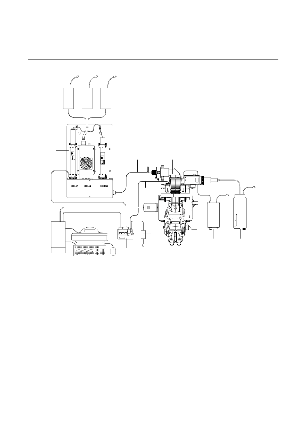
Photo activation illuminator unit and Ti-U (top view):
When used in combination with two-laser or three-laser unit
(Standard configuration to use the photo activation illuminator unit)
(1)
(2)
(4)
CLASS 3B
CAUTION
LASER RADIATION WHEN OPEN
AVOID EXPOSURE TO THE BEAM
(10)
RS-232C LASER UNIT
LASER SHUTTER
(3)
Exclusive use for TI-TIRF system
Don't use this unit with other systems.
* For details, see Section 8.1, “Overall Configuration,” in Chapter 8, “Specifications and Performance.”
(1) Power supply devices for the laser devices
(2) Laser unit (C-LU2, C-LU3, C-LU3EX)
(3) PC
(4) Optical fiber
(5) TI-LUSU shutter unit
(6) AC adapter for the shutter unit
(7) TV camera (video camera)
(8) TI-FLC epi-fl filter turret
(9) Power supply device for dia illumination
(10) Photo activation illuminator unit
(11) HG fiber light source
(12) Interlock cable
(5)
INPUT
12V
SAFETY
1A
COVER
CLOSE
BINO
CLOSE
POWER
TI-LUSU
(7)
LASER RADIATION
AVOID EXPOSURE TO BE
CLASS 3B LASER PROD
AVOID EXPOSURE
LASER LIGHT IS EMITTED
FROM
OBJECTIVE APERTURE
(6)
Figure 1.1-12
LASERSTRAHLUNG
CLASS 3B
CAUTION
LASER RADIATION WHEN OPEN
AVOID EXPOSURE TO THE BEAM
VORSICHT
KLASSE 3B,
WENN ABDECKUNG GEFFNET
NICHT DEM STRAHL AUSSETZEN
(8)
(9)
(11)
1-15
Page 30
Chapter 1 System Configurations and Part Names
(11)
1.1 Overview
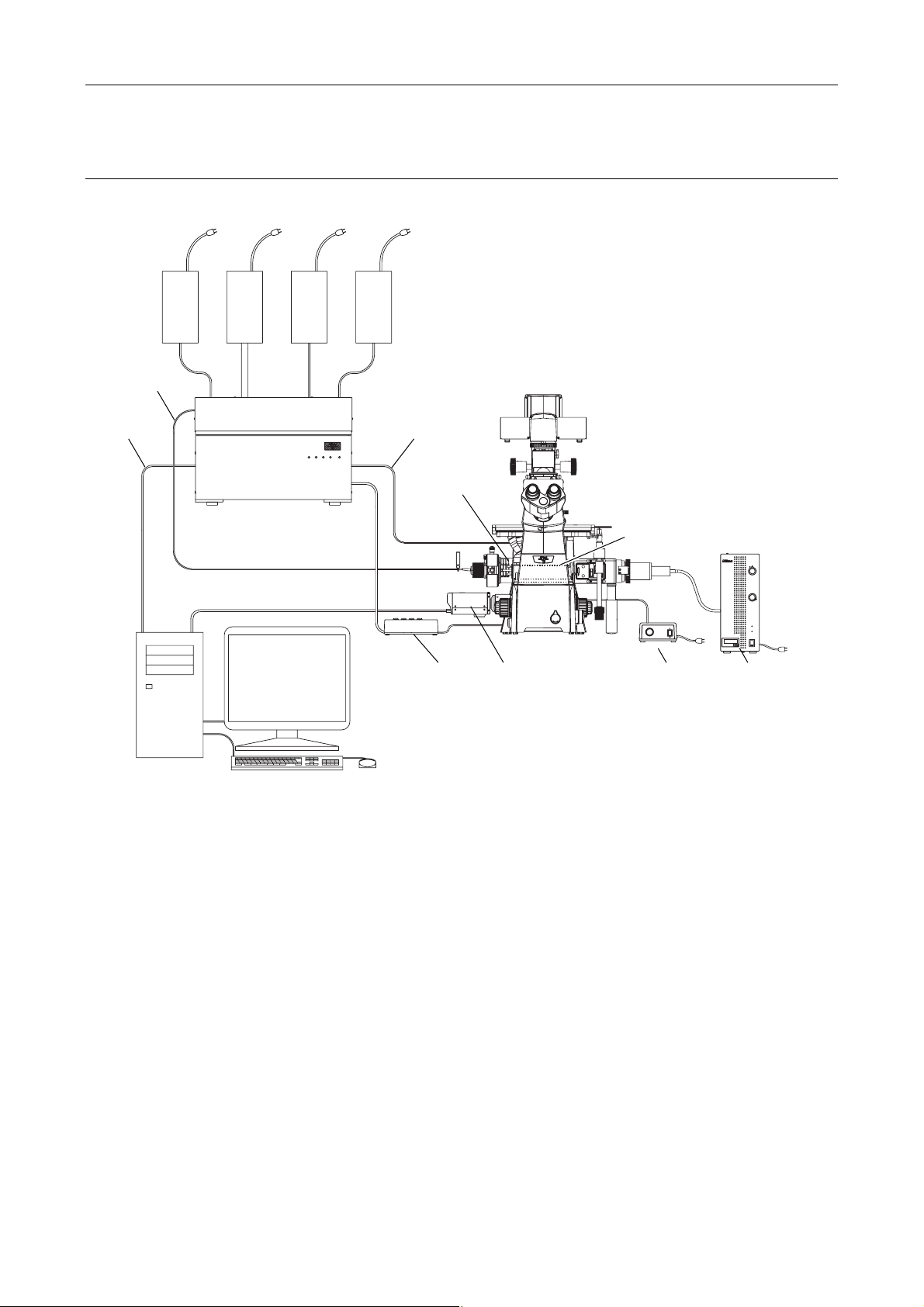
Photo activation illuminator unit and Ti-U (front view):
When used with four-laser module A
(Standard configuration to use the photo activation illuminator unit)
(1)
(4)
(12)
(2)
POWER
L3
L1
L4
L2
(3)
Figure 1.1-13
* For details, see Section 8.1, “Overall Configuration,” in Chapter 8, “Specifications and Performance.”
(1) Power supply devices for the laser devices
(2) Laser unit (LU4A)
(3) PC
(4) Optical fiber
(5) TI-LU4SU shutter unit LU4
(6) TV camera (video camera)
(7) TI-FLC epi-fl filter turret
(8) Power supply device for the diascopic illumination
(9) Photo activation illuminator unit
(10) HG fiber light source
(11) Interlock cable
(12) USB cable
(5)
(9)
(7)
CLASS 3B
–
CAUTION
LASER RADIATION WHEN OPEN
AVOID EXPOSURE TO THE BEAM
(6) (8) (10)
1-16
Page 31
Chapter 1 System Configurations and Part Names
(11)
1.1 Overview
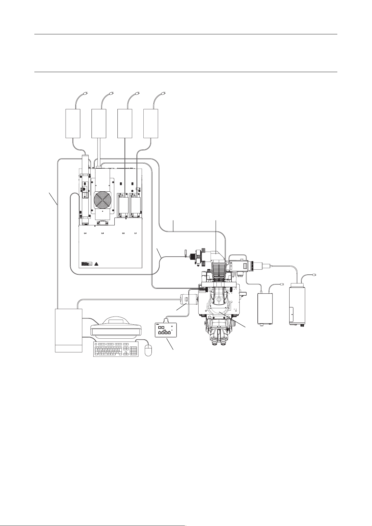
Photo activation illuminator unit and Ti-U (top view):
When used with four-laser module A
(Standard configuration to use the photo activation illuminator unit)
(1)
(2)
(12)
(4)
(3)
TI-LU4SU
Figure 1.1-14
* For details, see Section 8.1, “Overall Configuration,” in Chapter 8, “Specifications and Performance.”
(1) Power supply devices for the laser devices
(2) Laser unit (LU4A)
(3) PC
(4) Optical fiber
(5) TI-LU4SU shutter unit LU4
(6) TV camera (video camera)
(7) TI-FLC epi-fl filter turret
(8) Power supply device for the diascopic illumination
(9) Photo activation illuminator unit
(10) HG fiber light source
(11) Interlock cable
(12) USB cable
(5)
LASER
EMISSION
POWER
(6)
(9)
HE BEAM
EN OPEN
TO T
CLASS 3B
DIATION WH
POSURE
–
TION
ID EX
CAU
LASER RA
AVO
LASERSTRAHLUNG
CLASS 3B
–
–
CAUTION
LASER RADIATION WHEN OPEN
AVOID EXPOSURE TO THE BEAM
VORSICHT
KLASSE 3B,
WENN ABDECKUNG GEÖFFNET
NICHT DEM STRAHL AUSSETZEN
LASER RADIATION
AVOID EXPOSURE TO BE
CLASS 3B LASER PROD
AVOID EXPOSURE
LASER LIGHT IS EMITTED
FROM
OBJECTIVE APERTURE
(10)
(8)
(7)
1-17
Page 32
Chapter 1 System Configurations and Part Names
*
1
*
*
1
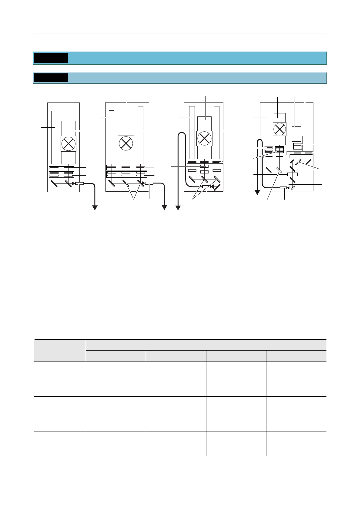
1.2 Optical Paths of Lasers
1.2 Optical Paths of Lasers
1.2.1 Laser Unit
(3)
(2)
(1)
(5)
(6)
(8) (7)
(1) Laser mounting position L1
(See the table below.)
(2) Laser mounting position L2
(See the table below.)
(3) Laser mounting position L3
(See the table below.)
(4) Laser mounting position L4
(See the table below.)
(5) Motorized shutters
(6) ND filters (ND4 and ND8)
Model name
(2)
(7)
(8)
(1)
(5)
(6)
(2)
(3)
(9)
(8)
(7)
C-LU3EX three-laser unit EXC-LU3 three-laser unitC-LU2 two-laser unit LU4A four-laser module A
(1)
(5)
(11)
(12)
(4)
1
(10)
(7)
(3)
(2) (1)
(8)
Figure 1.2-1
(7) Laser coupling mirror
(8) Laser outlet (single-mode optical fiber)
(9) Wavelength selection filter
(optional for C-LU3EX)
(10) AOTF brightness adjustment part
*1
(11)
ND filters (two ND32s)
*1
(12)
ND filters (ND2 and ND4)
*1: Installed only when the N-STORM kit is
mounted
Table 1.2-1
Laser mounting position
L1 L2 L3 L4
(11)
(5)
(7)
(5)
C-LU2
two-laser unit
C-LU3
three-laser unit
C-LU3EX
three-laser unit EX
LU4A
four-laser module A
405 nm to 514 nm 532 nm to 640 nm — —
405 nm to 445 nm
594 nm to 645 nm
405 nm to 445 nm
594 nm to 645 nm
488 nm to 514 nm
488 nm to 514 nm
532 nm to 561 nm
633 nm
532 nm to 561 nm
633 nm
—
—
630 nm to 650nm 400 nm to 445 nm 455 nm to 515 nm 540 nm to 595 nm
LU4A
four-laser module A
635 nm to 648 nm 400 nm to 445 nm 455 nm to 515 nm 540 nm to 595 nm
(for N-STORM)
1-18
Page 33
Chapter 1 System Configurations and Part Names
1.2 Optical Paths of Lasers
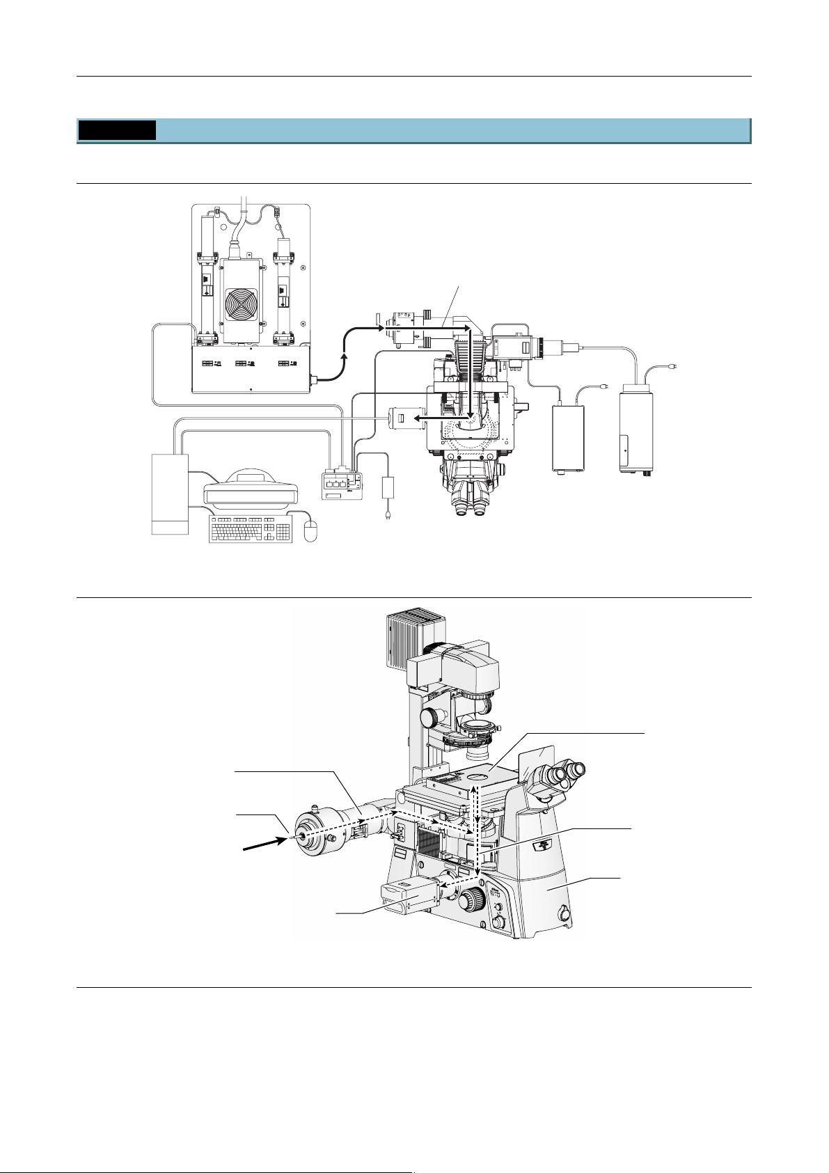
1.2.2 Microscope Part (TIRF Illuminator Unit and Ti-U System)
TIRF illuminator unit and Ti-U system (top view)
Laser light
CLASS 3B
–
LASER RADIATION WHEN OPEN
AVOID EXPOSURE TO THE BEAM
CAUTION
LASERSTRAHLUNG
CLASS 3B
–
–
KLASSE 3B,
WENN ABDECKUNG GEÖFFNET
NICHT DEM STRAHL AUSSETZEN
LASER RADIATION WHEN OPEN
AVOID EXPOSURE TO THE BEAM
VORSICHT
CAUTION
SER RADIATIO
OID EXPOSU
CLASS 3B LASE
AVOID EXPOSURE
LASER LIGHT IS EMITTE
FROM
OBJECTIVE APERT
INPUT
RS-232C LASER UNIT
12V
SAFETY
1A
LASER SHUTTER
COVER
CLOSE
BINO
CLOSE
POWER
TI-LUSU
Exclusive use for TI-TIRF system
Don't use this unit with other systems.
Figure 1.2-2
TIRF Illuminator Unit and Ti-U System (front left view)
C
A
U
T
IO
N
–
L
C
A
L
S
A
S
E
S
R
R
3
B
A
D
A
I
A
V
T
O
IO
I
D
N
E
W
X
H
P
E
O
N
S
O
U
R
P
E
E
N
T
O
T
H
V
E
O
B
R
E
S
A
I
C
M
H
T
K
–
L
A
L
S
A
S
S
E
E
R
3
S
B
W
T
,
R
E
A
N
H
N
L
A
U
N
B
G
D
N
E
IC
C
H
K
T
U
D
N
E
G
M
S
G
T
E
R
Ö
A
F
H
F
L
N
A
E
T
U
S
S
E
T
Z
E
N
TIRF Illuminator Unit
Optical fiber
Laser light
(from the laser unit)
TV camera
N
D
2
N
N
D
D
8
16
C
A
U
T
I
O
N
–
L
C
A
L
S
A
E
S
R
S
R
3
A
B
D
A
IA
V
O
T
I
I
O
D
N
E
W
X
P
H
O
E
S
N
U
O
R
P
E
T
O
T
V
H
O
E
R
B
S
E
I
C
H
T
K
–
L
A
L
S
A
S
S
E
E
R
3
W
S
B
T
,
E
R
N
A
N
H
L
A
U
B
N
N
D
I
E
C
C
H
K
T
U
D
N
E
G
M
S
G
T
E
R
Ö
A
F
H
F
L
N
A
E
U
S
S
E
T
Z
E
N
Figure 1.2-3
E
N
A
M
G
T
M
A
E
C
B
U
D
O
N
T
O
O
R
I
E
T
P
R
A
I
U
R
S
D
E
A
O
S
R
P
A
L
X
R
E
B
E
3
S
D
I
A
S
O
L
S
V
A
A
L
C
X
E
G
I
D
L
I
O
R
O
E
V
S
A
M
A
O
L
R
F
AVOID
EXPOSURE
LASER
LIGHT
FROM
IS
THIS
APERTURE
Laser safety cover
T
E
R
D
E
U
E
T
T
T
R
R
I
E
U
M
P
E
S
A
O
S
I
E
P
V
I
T
T
H
C
E
J
B
Epi-fl filter turret
EMITTED
C
A
U
T
I
O
N
–
C
L
A
L
A
S
S
E
S
R
R
3
B
A
D
A
IA
V
T
O
I
O
I
D
N
E
W
X
H
P
E
O
N
S
U
O
R
P
E
E
N
T
O
T
H
V
E
O
B
R
E
S
A
I
C
M
H
T
K
–
L
A
L
A
S
S
S
E
E
R
3
S
B
W
T
,
R
E
A
N
H
N
L
U
A
N
B
G
D
N
E
I
C
C
H
K
T
U
N
D
G
E
M
S
G
T
E
R
Ö
A
F
H
F
L
N
E
A
T
U
S
S
E
T
Z
E
N
ON
OFF
6V30W
12V100W
MAX.
Ti-U microscope body
Optical path
The TV camera can be installed in a side port (right or left port) or the bottom port (only for Ti-U/B). To
change the optical path, use the optical path selector knob on the microscope.
Note that the laser shutter automatically closes when the microscope optical path is changed to the eyepiece.
It is not possible to observe images obtained by irradiating the laser to the specimen, from the binocular part
of the microscope.
1-19
Page 34
Chapter 1 System Configurations and Part Names
1.2 Optical Paths of Lasers
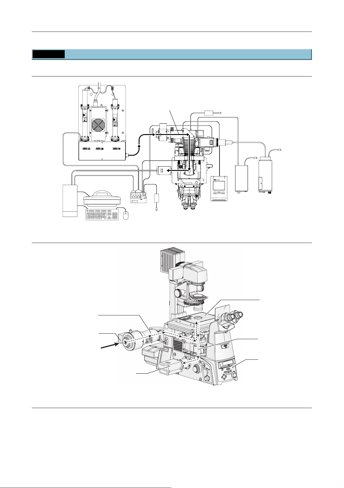
1.2.3 Microscope Part (Motorized TIRF Illuminator Unit and Ti-E System)
Motorized TIRF illuminator unit and Ti-E system (top view)
Laser light
CLASS 3B
CLASS 3B
–
–
CAUTION
LASER RADIATION WHEN OPEN
AVOID EXPOSURE TO THE BEAM
CAUTION
LASER RADIATION WHEN OPEN
AVOID EXPOSURE TO THE BEAM
LASERSTRAHLUNG
LASERSTRAHLUNG
CLASS 3B
CLASS 3B
–
–
–
–
LASER RADIATION WHEN OPEN
AVOID EXPOSURE TO THE BEAM
VORSICHT
KLASSE 3B,
WENN ABDECKUNG GEÖFFNET
NICHT DEM STRAHL AUSSETZEN
CAUTION
CAUTION
KLASSE 3B,
WENN ABDECKUNG GEÖFFNET
NICHT DEM STRAHL AUSSETZEN
LASER RADIATION WHEN OPEN
AVOID EXPOSURE TO THE BEAM
VORSICHT
SER RADIATIO
SER RADIATIO
OID EXPOSU
OID EXPOSU
CLASS 3B LASE
CLASS 3B LASE
AVOID EXPOSURE
AVOID EXPOSURE
LASER LIGHT IS EMITTE
LASER LIGHT IS EMITTE
OBJECTIVE APERT
FROM
OBJECTIVE APERT
FROM
INPUT
RS-232C LASER UNIT
12V
SAFETY
1A
LASER SHUTTER
COVER
CLOSE
BINO
CLOSE
POWER
TI-LUSU
Exclusive use for TI-TIRF system
Don't use this unit with other systems.
Figure 1.2-4
Motorized TIRF illuminator unit and Ti-E system (front left view)
C
A
U
T
I
O
N
–
L
C
A
L
S
A
E
S
S
R
R
3
B
A
D
A
I
A
V
T
O
I
O
I
D
N
E
W
X
H
P
E
O
N
S
U
O
R
P
E
E
N
T
O
T
H
V
E
O
B
R
E
S
A
I
C
M
H
T
K
–
L
A
L
S
A
S
S
E
E
R
3
S
B
W
T
,
R
E
A
N
H
N
L
U
A
N
B
G
D
N
E
I
C
C
H
K
T
U
D
N
E
G
M
S
G
T
E
R
Ö
A
F
H
F
L
N
E
A
T
U
S
S
E
T
Z
E
N
Motorized TIRF
Illuminator Unit
Optical fiber
Laser light
(from the laser unit)
TV camera
N
D
2
N
N
D
D
8
16
C
A
U
T
I
O
N
–
L
C
A
L
S
A
E
S
R
S
R
3
A
B
D
A
I
V
A
O
T
I
I
O
D
N
E
W
X
P
H
O
E
S
N
U
O
R
P
E
T
O
T
V
H
O
E
R
B
S
E
I
C
H
T
K
–
L
A
L
S
A
S
S
E
E
R
3
W
S
B
T
,
E
R
N
A
N
H
L
A
U
B
N
N
D
G
I
E
C
C
H
K
T
U
D
N
E
G
M
S
G
T
E
R
Ö
A
H
F
F
L
N
A
E
U
S
S
E
T
Z
E
N
Figure 1.2-5
E
N
A
M
T
M
A
T
E
C
B
U
D
O
N
T
O
O
R
I
E
T
P
R
A
I
U
R
S
D
E
A
O
S
R
P
A
L
X
R
E
B
E
3
S
D
I
A
S
O
L
S
V
A
A
L
C
E
R
D
E
U
E
T
T
T
R
R
I
E
U
M
P
E
S
A
O
S
I
E
P
V
I
T
X
T
H
E
C
G
I
E
D
L
J
I
B
O
R
O
E
V
S
A
M
A
O
L
R
F
A
V
O
ID
E
L
X
A
P
S
O
E
R
S
U
L
I
R
G
F
E
H
R
T
O
M
I
S
T
E
H
M
IS
IT
T
A
E
P
D
E
R
T
U
R
C
E
A
U
T
I
O
N
–
C
L
A
L
A
S
S
E
S
R
R
3
B
A
D
A
I
A
V
T
O
I
O
I
D
N
E
W
X
H
P
E
O
N
S
U
O
R
P
E
E
N
T
O
T
H
V
E
O
B
R
E
S
A
I
C
M
H
T
K
–
L
A
L
A
S
S
S
E
E
R
3
S
B
W
T
,
R
E
A
N
H
N
L
U
A
N
B
G
D
N
E
I
C
C
H
K
T
U
N
D
G
E
M
S
G
T
E
R
Ö
A
F
H
F
L
N
E
A
T
U
S
S
E
T
Z
E
N
Coarse
Fine
ExFine
Obj.
ON/OF
F
6V30W
12V100W
MAX.
Laser safety cover
Motorized epi-fl filter turret
Ti-E microscope body
RESET
Z
DISPLAY
BRIGHTNESS
RECALL
FOCUS
EYE
MEMORY
ON
PFS
R100
L100
L80
Optical path
The TV camera can be installed in a side port (right or left port) or the bottom port (only for Ti-E/B). To
change the optical path, use the optical path selector switch on the microscope.
Note that the laser shutter automatically closes when the microscope optical path is changed to the eyepiece.
It is not possible to observe images obtained by irradiating the laser to the specimen, from the binocular part
of the microscope.
1-20
Page 35
Chapter 1 System Configurations and Part Names
1.2 Optical Paths of Lasers
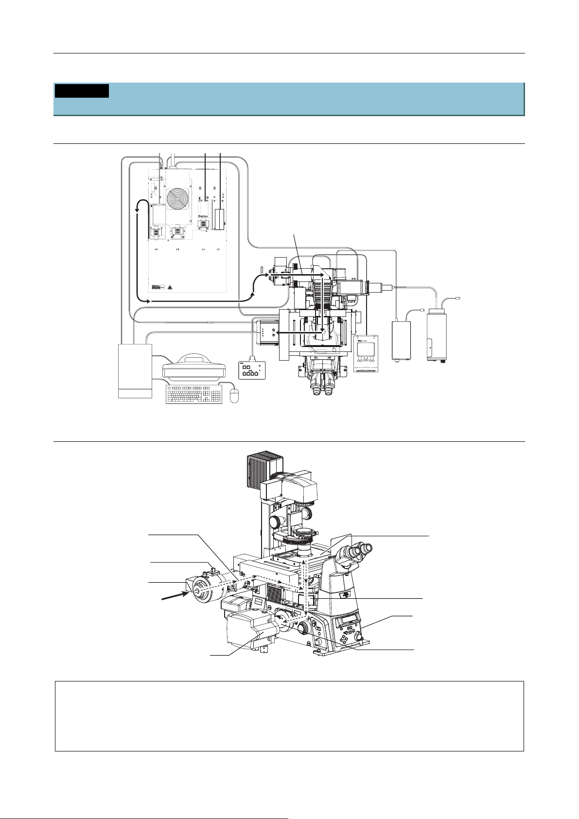
1.2.4 Microscope Part (Motorized TIRF Illuminator Unit, LU4A, N-STORM, and
Ti-E System)
Motorized TIRF Illuminator Unit, LU4A, N-STORM, and Ti-E System (top view)
transportation.
Fix the laser unit with
four blocks during
Laser light
CLASS 3B
CLASS 3B
–
–
CAUTION
LASER RADIATION WHEN OPEN
AVOID EXPOSURE TO THE BEAM
LASER RADIATION WHEN OPEN
AVOID EXPOSURE TO THE BEAM
CAUTION
TI-LU4SU
LASER
EMISSION
POWER
Figure 1.2-6
Motorized TIRF Illuminator Unit, LU4A, N-STORM, and Ti-E System (front left view)
C
A
U
T
I
O
N
–
L
C
A
L
S
A
E
S
S
R
R
3
B
A
D
A
I
A
V
T
O
I
O
I
D
N
E
W
X
H
P
E
O
N
S
U
O
R
P
E
E
N
T
O
T
H
V
E
O
B
R
E
S
A
I
C
M
H
T
K
–
L
A
L
S
A
S
S
E
E
R
3
S
B
W
T
,
R
E
A
N
H
N
L
U
A
N
B
G
D
N
E
I
C
C
H
K
T
U
D
N
E
G
M
S
G
T
E
R
Ö
A
F
H
F
L
N
E
A
T
U
S
S
E
T
Z
E
N
Motorized TIRF
Illuminator Unit
STORM slider
Optical fiber
Laser light
(from the laser unit)
M
A
T
C
BE
U
D
N
TO
O
O
R
I
E
T
R
P
A
I
U
R
S
D
E
A
O
S
R
P
A
X
L
R
B
E
E
S
3
ID
A
S
O
L
S
V
A
A
L
C
E
R
D
E
U
E
T
T
T
R
R
I
E
U
M
P
E
S
A
O
IS
E
P
IV
T
X
T
H
E
C
IG
E
L
J
ID
B
O
R
O
E
V
S
A
M
A
O
L
R
F
C
A
U
T
I
O
N
–
L
C
A
L
S
A
E
S
R
S
R
3
A
B
D
A
I
V
A
O
T
I
I
O
D
N
E
W
X
P
H
O
E
S
N
U
O
R
P
E
E
T
N
O
T
V
H
O
E
R
B
S
E
I
C
A
H
M
T
K
–
L
A
L
S
A
S
S
E
E
R
3
W
S
B
T
,
E
R
N
A
N
H
L
A
U
B
N
N
D
G
I
E
C
C
H
K
T
U
D
N
E
G
M
S
G
T
E
R
Ö
A
F
H
F
L
N
A
E
U
T
S
S
E
T
Z
E
N
AV
O
ID
E
L
X
A
P
S
O
E
R
SU
L
IG
RE
F
H
R
T
O
M
IS
T
E
H
M
IS
IT
T
A
E
P
D
E
R
T
U
R
C
E
A
U
T
I
O
N
–
C
L
A
L
A
S
S
E
S
R
R
3
B
A
D
A
I
A
V
T
O
I
O
I
D
N
E
W
X
H
P
E
O
N
S
U
O
R
P
E
E
N
T
O
T
H
V
E
O
B
R
E
S
A
I
C
M
H
T
K
–
L
A
L
A
S
S
S
E
E
R
3
S
B
W
T
,
R
E
A
N
H
N
L
U
A
N
B
G
D
N
E
I
C
C
H
K
T
U
D
N
E
G
M
S
G
T
E
R
Ö
A
F
H
F
L
N
E
A
T
U
S
S
E
T
Z
E
N
Laser safety cover
Motorized Epi-fl Filter Turret
Ti-E microscope body
EM-CCD camera
3D-STORM port
Figure 1.2-7
The 3D-STORM port can be installed in a side port (right or left port). To change the optical path, use the
optical path selector switch on the microscope.
Note that the laser shutter automatically closes when the microscope optical path is changed to the
eyepiece. It is not possible to observe images obtained by irradiating the laser to the specimen, from the
binocular part of the microscope.
1-21
Page 36

Chapter 1 System Configurations and Part Names
1.2 Optical Paths of Lasers
1.2.5 Microscope Part (Photo Activation Illuminator Unit and Ti-U System)
TI-PAU photo activation illuminator unit and Ti-U system (top view)
Laser light
CLASS 3B
CAUTION
LASER RADIATION WHEN OPEN
AVOID EXPOSURE TO THE BEAM
LASERSTRAHLUNG
CLASS 3B
CAUTION
LASER RADIATION WHEN OPEN
AVOID EXPOSURE TO THE BEAM
VORSICHT
KLASSE 3B,
WENN ABDECKUNG GEFFNET
NICHT DEM STRAHL AUSSETZEN
LASER RADIATION
AVOID EXPOSURE TO BE
CLASS 3B LASER PROD
AVOID EXPOSURE
LASER LIGHT IS EMITTED
FROM
OBJECTIVE APERTURE
INPUT
RS-232C LASER UNIT
12V
SAFETY
1A
LASER SHUTTER
COVER
CLOSE
BINO
CLOSE
POWER
TI-LUSU
Exclusive use for TI-TIRF system
Don't use this unit with other systems.
Figure 1.2-8
TI-PAU photo activation illuminator unit and Ti-U system
C
A
U
T
I
O
N
–
L
C
A
L
S
A
E
S
S
R
R
3
B
A
D
A
I
A
V
T
O
I
O
I
D
N
E
W
X
H
P
E
O
N
S
U
O
R
P
E
E
N
T
O
T
H
V
E
O
B
R
E
S
A
I
C
M
H
T
K
–
L
A
L
S
A
S
S
E
E
R
3
S
B
W
T
,
R
E
A
N
H
N
L
U
A
N
B
G
D
N
E
I
C
C
H
K
T
U
D
N
E
G
M
S
G
T
E
R
Ö
A
F
H
F
L
N
E
A
T
U
S
S
E
T
Z
E
N
Motorized TIRF
Illuminator Unit
Optical fiber
Laser light
(from the laser unit)
TV camera
N
N
N
D
D
D
16
8
2
M
A
T
E
C
B
U
D
O
N
T
O
O
R
I
E
T
P
R
A
I
U
R
S
D
E
A
O
S
R
P
A
L
X
R
E
B
E
3
S
D
I
A
S
O
L
S
V
A
A
L
C
E
E
TUR
R
ITTED
U
M
PER
E
S
A
O
S
I
P
IVE
T
X
T
E
EC
D
LIGH
I
O
R
OBJ
V
SE
A
OM
LA
FR
C
A
U
T
I
O
N
–
L
C
A
L
S
A
E
S
R
S
R
3
A
B
D
A
I
V
A
O
T
I
I
O
D
N
E
W
X
P
H
O
E
S
N
U
O
R
P
E
E
T
N
O
T
V
H
O
E
R
B
S
E
I
C
A
H
M
T
K
–
L
A
L
S
A
S
S
E
E
R
3
W
S
B
T
,
E
R
N
A
N
H
L
A
U
B
N
N
D
G
I
E
C
C
H
K
T
U
D
N
E
G
M
S
G
T
E
R
Ö
A
F
H
F
L
N
A
E
U
T
S
S
E
T
Z
E
N
AVO
ID
EXPO
LASER
SU
LIG
RE
FRO
H
T
M
IS
TH
EM
IS
APER
TU
Figure 1.2-9
ITTED
R
C
E
A
U
T
I
O
N
–
C
L
A
L
A
S
S
E
S
R
R
3
B
A
D
A
I
A
V
T
O
I
O
I
D
N
E
W
X
H
P
E
O
N
S
U
O
R
P
E
E
N
T
O
T
H
V
E
O
B
R
E
S
A
I
C
M
H
T
K
–
L
A
L
A
S
S
S
E
E
R
3
S
B
W
T
,
R
E
A
N
H
N
L
U
A
N
B
G
D
N
E
I
C
C
H
K
T
U
N
D
G
E
M
S
G
T
E
R
Ö
A
F
H
F
L
N
E
A
T
U
S
S
E
T
Z
E
N
Laser safety cover
Motorized epi-fl filter turret
Ti-E microscope body
ON
OFF
6V30W
12V100W
MAX.
1-22
Page 37
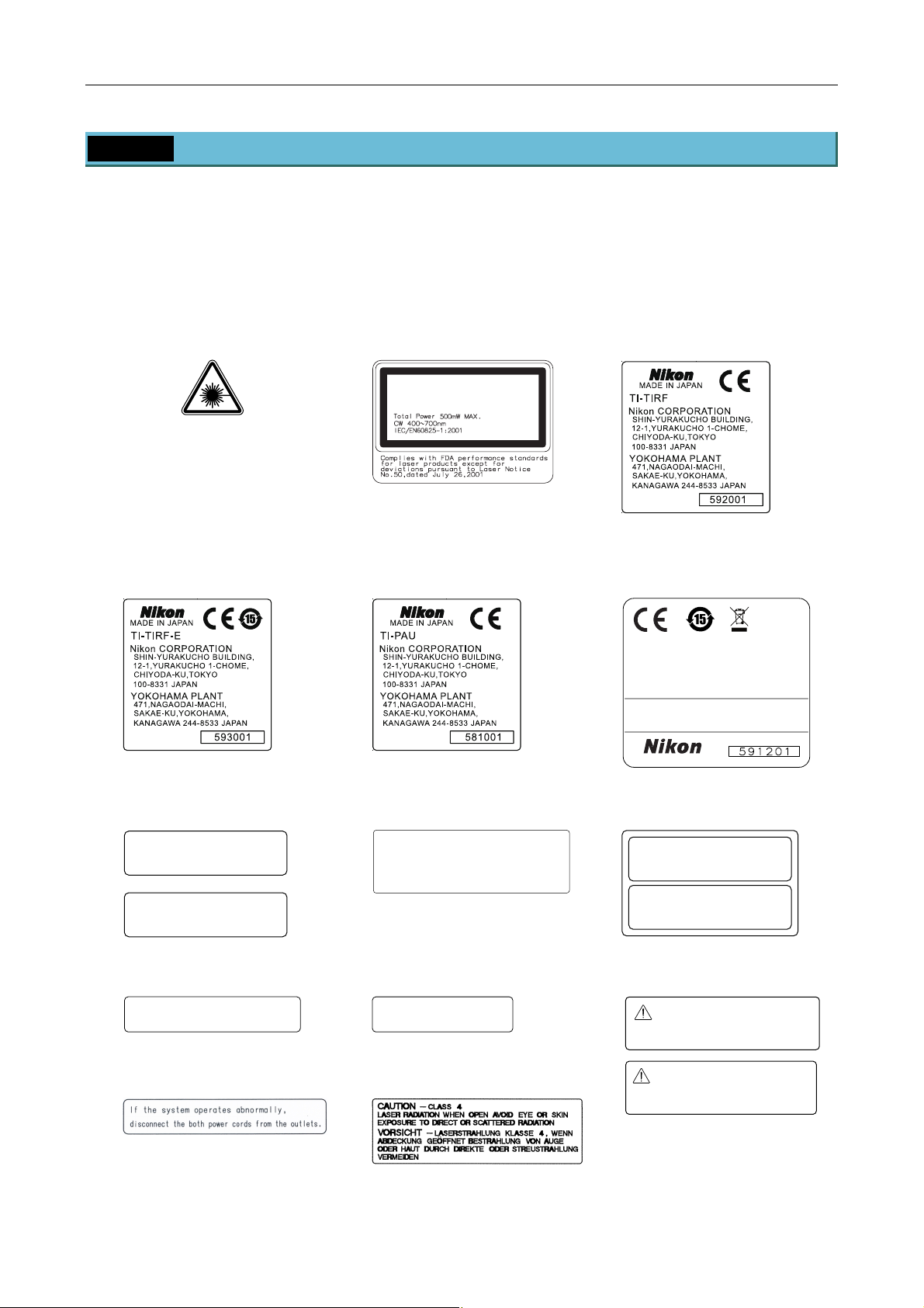
Chapter 1 System Configurations and Part Names
1.3 Safety Labels and Openings
1.3 Safety Labels and Openings
The following shows the types and locations of the safety labels affixed to each unit picture, as well as the
openings provided in the product. The labels to be affixed to the microscope are shipped with the TIRF
illuminator unit/motorized TIRF illuminator unit/photo activation illuminator unit, and the laser safety kit. Affix
these labels in place when setting up TIRF-PAU. The other labels are already affixed in place when
shipped.
(1) IEC warning label -
laser hazard symbol
(2) IEC explanatory label -
Class 3B laser product
LASER RADIATION
AVOID EXPOSURE TO BEAM
CLASS 3B LASER PRODUCT
(3) Model name and serial
number label
TI-TIRF
TI-TIRF-E TI-PAU (4) Safety standard label
TI-LUSU/TI-LU4SU
This device complies with Part 15 of the FCC Rules.
Operation is subject to the following two
conditions:
(1) this device may not cause harmful interference,
and
(2) this device must accept any interference received,
including interference that may cause undesired
operation.
This Class A digital apparatus complies with Canadian
ICES-003.
Cet appareil numérique de la classe A est confirme
à la norme NMB-003 du Canada.
MADE IN JAPAN
(5) IEC caution label -
Class 3B area
CAUTION – CLASS 3B
LASER RADIATION WHEN OPEN
AVOID EXPOSURE TO THE BEAM
–
VORSICHT
KLASSE 3B,
WENN ABDECKUNG GEÖFFNET
NICHT DEM STRAHL AUSSETZEN
LASERSTRAHLUNG
(6) IEC caution label -
Class 3B area
CAUTION
– CLASS 3B
RADIATION WHEN OPEN
LASER
AVOI D
EXPOSURE TO THE BEAM
VORSICHT
WENN
NICHT
– LASERSTRAHLUNG KLASSE 3B,
ABDECKUNG GEÖFFNET
DEM STRAHL AUSSETZEN
(7) IEC caution label -
Class 3B area
CAUTION – CLASS 3B
LASER RADIATION WHEN OPEN
AVOID EXPOSURE TO THE BEAM
VORSICHT
KLASSE 3B,
WENN ABDECKUNG GEÖFFNET
NICHT DEM STRAHL AUSSETZEN
–
LASERSTRAHLUNG
(8) IEC aperture label 1 (9) IEC aperture label 2 (10) TI-TIRF special label
TI-PAU special label
AVOID EXPOSURE
LASER LIGHT IS EMITTED
OBJECTIVE APERTURE
FROM
AVOID EXPOSURE
LASER LIGHT IS EMITTED
FROM
THIS APERTURE
Exclusive use for TI-TIRF system
Don't use this unit with other systems.
(11) Caution label (12) IEC caution label - Class 4
area
Exclusive use for TI-PAU system
Don't use this unit with other systems.
1-23
Page 38
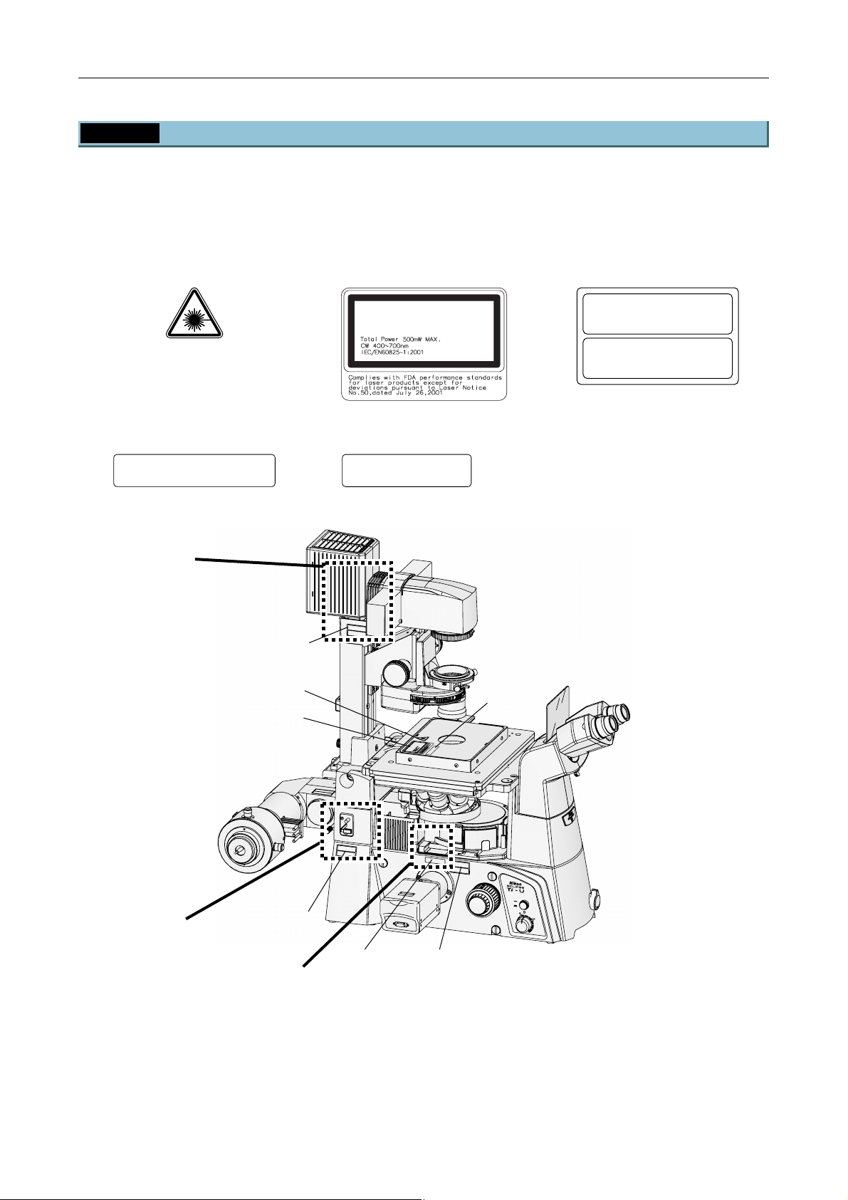
Chapter 1 System Configurations and Part Names
1.3 Safety Labels and Openings
1.3.1 Ti-U Microscope Body (with the TIRF Illuminator Unit)
Be sure to affix each label to the positions indicated in the figure below.
The microscope body has three openings, A to C, as shown below. Near each of the openings, affix the
following labels at the positions shown below.
(1) IEC warning label -
laser hazard symbol
(2) IEC explanatory label -
Class 3B laser product
(7) IEC caution label -
Class 3B area
LASER RADIATION
AVOID EXPOSURE TO BEAM
CLASS 3B LASER PRODUCT
(8) IEC aperture label 1 (9) IEC aperture label 2
AVOID EXPOSURE
LASER LIGHT IS EMITTED
OBJECTIVE APERTURE
FROM
A
(7)
(1)
(2)
AVOID EXPOSURE
LASER LIGHT IS EMITTED
THIS APERTURE
FROM
C
A
U
T
IO
N
–
C
L
A
S
S
3B
L
A
S
E
R
R
A
D
IA
T
IO
N
W
A
V
H
O
E
ID
N
O
E
P
X
E
P
N
O
S
U
R
E
T
O
T
H
E
B
E
A
M
V
O
R
S
IC
H
T
–
L
A
S
E
K
R
L
S
A
T
S
R
S
A
E
H
3
L
B
U
,
N
G
W
E
N
N
A
B
D
E
C
K
U
N
N
G
IC
G
H
T
E
D
Ö
E
M
F
F
S
N
T
E
R
T
A
H
L
A
U
S
S
E
T
Z
E
N
M
T
A
C
E
U
B
D
O
O
R
T
N
E
P
IO
R
R
T
U
E
S
IA
E
S
R
D
O
A
U
D
A
P
L
T
E
X
R
T
B
R
E
T
E
I
E
R
3
P
R
M
E
S
A
ID
U
E
S
S
S
E
O
S
A
A
V
I
V
O
I
L
L
T
A
P
T
C
C
H
X
E
G
E
J
I
B
L
O
ID
R
O
E
M
S
V
O
A
A
R
L
F
(8)
CAUTION – CLASS 3B
LASER RADIATION WHEN OPEN
AVOID EXPOSURE TO THE BEAM
–
VORSICHT
KLASSE 3B,
WENN ABDECKUNG GEÖFFNET
NICHT DEM STRAHL AUSSETZEN
LASERSTRAHLUNG
C
A
U
T
IO
N
–
C
L
A
S
S
3
L
A
B
S
E
R
R
A
D
IA
T
IO
N
W
A
V
H
O
E
ID
N
E
O
X
P
P
E
O
N
S
U
R
E
T
O
T
H
E
B
E
A
M
V
O
R
S
IC
H
T
–
L
A
S
E
K
R
L
A
S
S
T
S
R
E
A
3
H
L
B
U
,
N
G
W
E
N
N
A
B
D
E
C
K
U
N
N
IC
G
G
H
T
D
E
E
Ö
M
F
F
S
N
T
E
R
T
A
H
L
A
U
S
S
E
T
Z
E
N
B
(7)
A
V
O
ID
E
X
P
O
S
U
LASER
R
E
LIG
HT
IS
FROM
EM
ITTED
TH
IS
CA
APERTURE
UTION
–
CLASS
3B
LASE
R R
ADIATIO
N W
AVO
HEN
ID EXPO
OPEN
SU
RE TO
TH
E BEAM
VORSICHT
–
LASE
KLASSE
RSTRAH
3B,
LUNG
W
E
NN
ABD
EC
KU
NG
NICH
G
T D
EÖ
EM
FFNET
STRA
HL AUSS
ETZE
N
ON
OFF
6V30W
12V100W
MAX.
C
(9) (both sides)
(7) (both sides)
Figure 1.3-1
1-24
Page 39
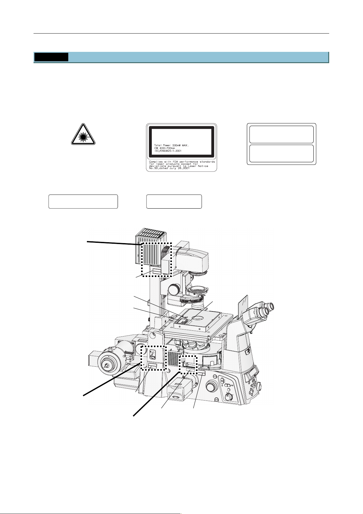
Chapter 1 System Configurations and Part Names
1.3 Safety Labels and Openings
1.3.2 Ti-E Microscope Body (with the Motorized TIRF Illuminator Unit)
Be sure to affix each label to the positions indicated in the figure below.
The microscope body has three openings, A to C, as shown below. Near each of the openings, affix the
following labels at the positions shown below.
(1) IEC warning label -
laser hazard symbol
(2) IEC explanatory label -
Class 3B laser product
(7) IEC caution label -
Class 3B area
LASER RADIATION
AVOID EXPOSURE TO BEAM
CLASS 3B LASER PRODUCT
(8) IEC aperture label 1 (9) IEC aperture label 2
AVOID EXPOSURE
LASER LIGHT IS EMITTED
OBJECTIVE APERTURE
FROM
A
(7)
(1)
(2)
AVOID EXPOSURE
LASER LIGHT IS EMITTED
THIS APERTURE
FROM
C
A
U
T
IO
N
–
C
L
A
S
S
3
L
B
A
S
E
R
R
A
D
IA
T
IO
N
W
A
V
H
O
E
ID
N
E
O
P
X
E
P
N
O
S
U
R
E
T
O
T
H
E
B
E
A
M
V
O
R
S
IC
H
T
–
L
A
S
E
K
R
L
S
A
T
S
R
S
A
E
H
3
L
B
U
,
N
G
W
E
N
N
A
B
D
E
C
K
U
N
N
G
IC
G
H
T
D
E
Ö
E
M
F
F
S
N
T
E
R
T
A
H
L
A
U
S
S
E
T
Z
E
N
(8)
CAUTION – CLASS 3B
LASER RADIATION WHEN OPEN
AVOID EXPOSURE TO THE BEAM
–
VORSICHT
KLASSE 3B,
WENN ABDECKUNG GEÖFFNET
NICHT DEM STRAHL AUSSETZEN
LASERSTRAHLUNG
M
T
A
C
E
U
B
D
O
O
T
R
N
P
E
O
I
R
R
T
U
E
A
S
I
S
E
D
O
A
R
L
A
P
U
D
T
E
X
R
B
R
T
E
E
3
E
R
IT
R
P
D
M
E
S
A
I
U
E
S
S
S
O
E
A
A
S
I
V
O
IV
L
L
A
T
P
T
C
C
X
H
E
G
E
J
I
B
L
D
O
I
R
E
O
M
S
V
O
A
A
R
L
F
C
A
U
T
IO
N
–
C
L
A
S
S
3
L
A
B
S
E
R
R
A
D
IA
T
IO
N
W
A
V
H
O
E
ID
N
E
O
X
P
P
E
O
N
S
U
R
E
T
O
T
H
E
B
E
A
M
V
O
R
S
IC
H
T
–
L
A
S
E
K
R
L
A
S
S
T
S
R
E
A
H
3
L
B
U
,
N
G
W
E
N
N
A
B
D
E
C
K
U
N
N
IC
G
G
H
T
D
E
E
Ö
M
F
F
S
N
T
E
R
T
A
H
L A
U
S
S
E
T
Z
E
N
B
(7)
(9) (both sides)
C
A
V
OID
E
X
P
O
S
LASE
U
R
E
R
LIG
HT
IS
FR
E
M
OM
ITTE
TH
D
IS
CAUTIO
A
PERTU
N
–
C
LASS 3B
R
E
LASER RAD
IA
TIO
N WHEN
AVOID
OPEN
EXPOSUR
E
TO
THE BEAM
VOR
S
IC
HT
–
LASER
KLA
S
TR
SSE
AH
3B
LU
NG
,
WENN ABDEC
KUNG GEÖFFN
NICHT DEM
STRAHL A
E
T
USSETZEN
(7) (both sides)
RESET
-
Coarse
Fine
ExFine
Obj.
ON/OF
F
6V30W
12V100W
MAX.
Z
DISPLAY
RECALL
BRIGHTNESS
Y
MEMOR
FOCUS
PFS
ON
EYE
R100
L100
L80
Figure 1.3-2
1-25
Page 40
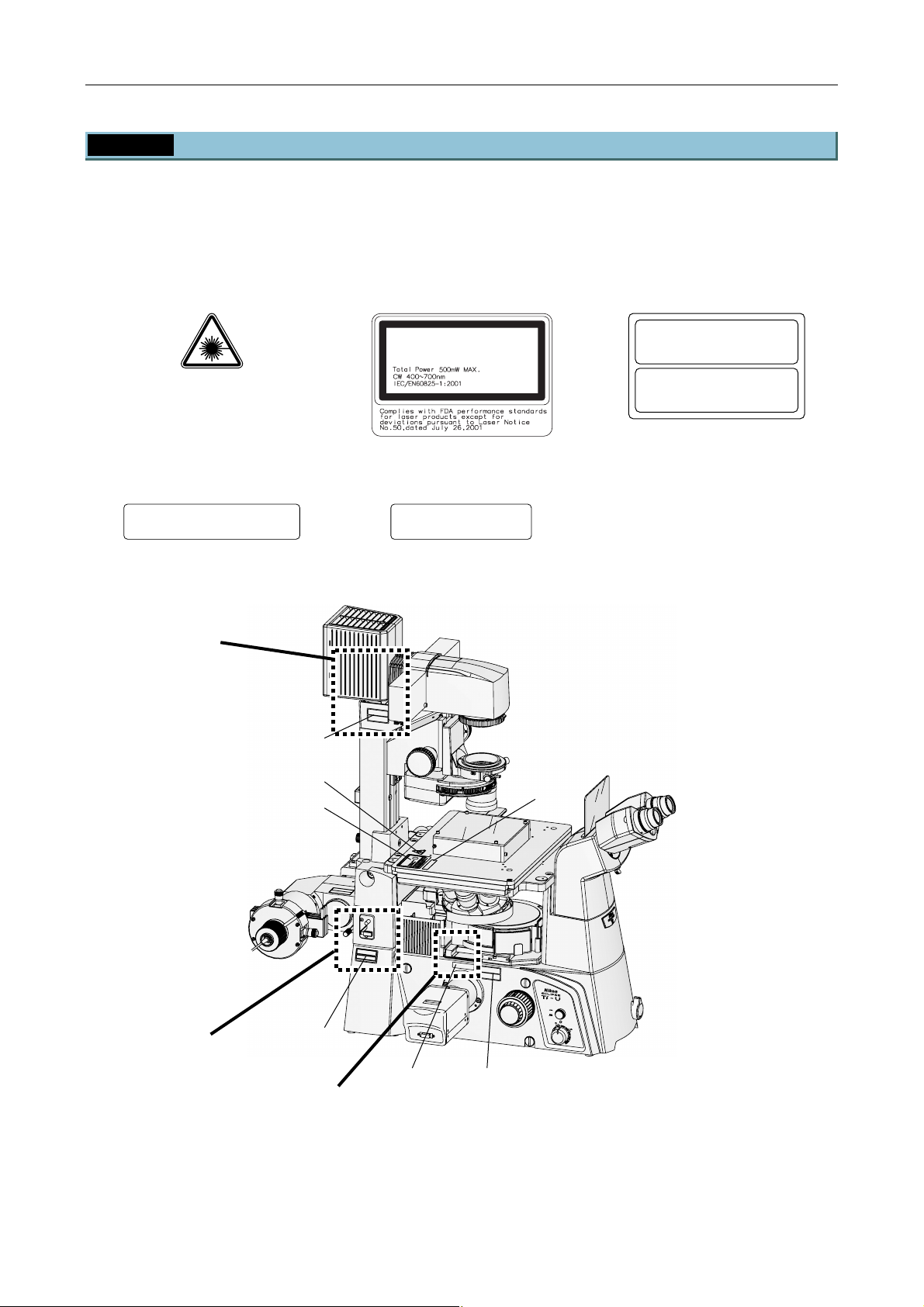
Chapter 1 System Configurations and Part Names
1.3 Safety Labels and Openings
1.3.3 Ti-U Microscope Body (with the TI-PAU Photo Activation Illuminator Unit)
Be sure to affix each label to the positions indicated in the figure below.
The microscope body has three openings, A to C, as shown below. Near each of the openings, affix the
following labels at the positions shown below.
(1) IEC warning label -
laser hazard symbol
(2) IEC explanatory label -
Class 3B laser product
(7) IEC caution label -
Class 3B area
LASER RADIATION
AVOID EXPOSURE TO BEAM
CLASS 3B LASER PRODUCT
(8) IEC aperture label 1 (9) IEC aperture label 2
AVOID EXPOSURE
LASER LIGHT IS EMITTED
FROM
OBJECTIVE APERTURE
AVOID EXPOSURE
LASER LIGHT IS EMITTED
THIS APERTURE
FROM
A
C
A
U
T
IO
N
–
C
L
A
S
S
3
L
B
A
S
E
R
R
A
D
IA
T
IO
N
W
A
V
H
O
E
ID
N
O
E
P
X
E
P
N
O
S
U
R
E
T
O
T
H
E
B
E
A
M
V
O
R
S
IC
H
T
–
L
A
S
E
K
R
L
S
A
T
S
R
S
A
E
H
3
L
B
U
,
N
G
W
E
N
N
A
B
D
E
C
K
U
N
N
G
IC
H
G
T
D
E
Ö
E
M
F
F
S
N
T
E
R
T
A
H
L
A
U
S
S
E
T
Z
E
N
(7)
CAUTION – CLASS 3B
LASER RADIATION WHEN OPEN
AVOID EXPOSURE TO THE BEAM
–
VORSICHT
KLASSE 3B,
WENN ABDECKUNG GEÖFFNET
NICHT DEM STRAHL AUSSETZEN
LASERSTRAHLUNG
(1)
(8)
(2)
M
M
T
T
A
A
C
C
E
E
U
U
B
B
D
D
O
O
O
O
R
R
T
T
N
N
E
E
P
P
IO
IO
R
R
R
R
T
T
U
U
E
E
S
S
IA
IA
E
E
S
S
R
R
D
D
O
O
A
A
U
U
D
D
A
A
P
P
L
L
T
T
E
E
X
X
R
R
T
T
B
B
R
R
E
E
T
T
E
E
E
E
I
I
R
R
3
3
P
P
R
R
M
M
E
E
S
S
A
A
ID
ID
U
U
E
E
S
S
S
S
S
S
E
E
O
O
S
S
A
A
A
A
V
V
I
I
V
V
O
O
I
I
L
L
L
L
T
T
A
A
P
P
T
T
C
C
C
C
H
H
X
X
E
E
G
G
E
E
J
J
I
I
B
B
L
L
O
O
ID
ID
R
R
O
O
E
E
M
M
S
S
V
V
O
O
A
A
A
A
R
R
L
L
F
F
C
A
U
T
IO
C
N
A
U
–
T
IO
C
L
N
A
L
–
S
A
S
C
S
3
L
E
A
B
R
S
R
S
3
A
L
D
A
B
IA
S
E
T
R
IO
A
R
V
N
O
A
W
D
ID
IA
H
E
E
T
X
IO
N
P
O
N
O
W
P
S
A
E
V
U
H
N
O
R
E
ID
E
N
T
E
O
O
X
P
T
P
E
O
H
N
S
E
U
B
R
E
E
A
T
M
V
O
O
T
R
H
S
E
IC
B
H
E
T
A
–
M
L
K
A
L
S
A
E
S
R
S
V
S
E
O
T
R
R
3
A
B
S
H
IC
,
L
H
W
U
T
N
E
–
N
G
L
N
A
A
S
B
E
K
D
R
L
A
E
S
S
T
C
N
S
R
K
IC
E
A
U
3
H
H
N
L
T
G
B
U
D
,
N
E
G
G
M
E
Ö
S
W
T
F
E
R
F
N
N
A
N
H
E
A
T
L
A
B
D
U
E
S
C
S
K
E
U
T
N
N
Z
IC
G
E
G
N
H
T
D
E
E
Ö
M
F
F
S
N
T
E
R
T
A
H
L
A
U
S
S
E
T
Z
E
N
B
(7)
A
V
O
ID
E
X
P
O
S
U
LASER
R
E
LIGHT
IS
FROM
EMITTED
THIS
C
AU
APERTURE
T
ION
–
C
LA
S
S
3B
LA
S
ER
R
A
D
IAT
IO
N
W
A
V
H
O
E
N
ID EX
O
P
E
PO
N
S
U
RE
T
O
TH
E B
EA
M
VO
R
S
IC
HT
–
LA
SE
K
R
LA
ST
S
RA
S
E
H
3B,
LU
NG
W
E
N
N
A
B
D
E
C
KU
N
N
G
IC
G
H
T
D
E
Ö
EM
F
FN
S
TR
E
T
A
H
L A
U
S
SE
TZ
E
N
ON
OFF
6V30W
12V100W
MAX.
C
(9) (both sides) (7) (both sides)
Figure 1.3-3
1-26
Page 41
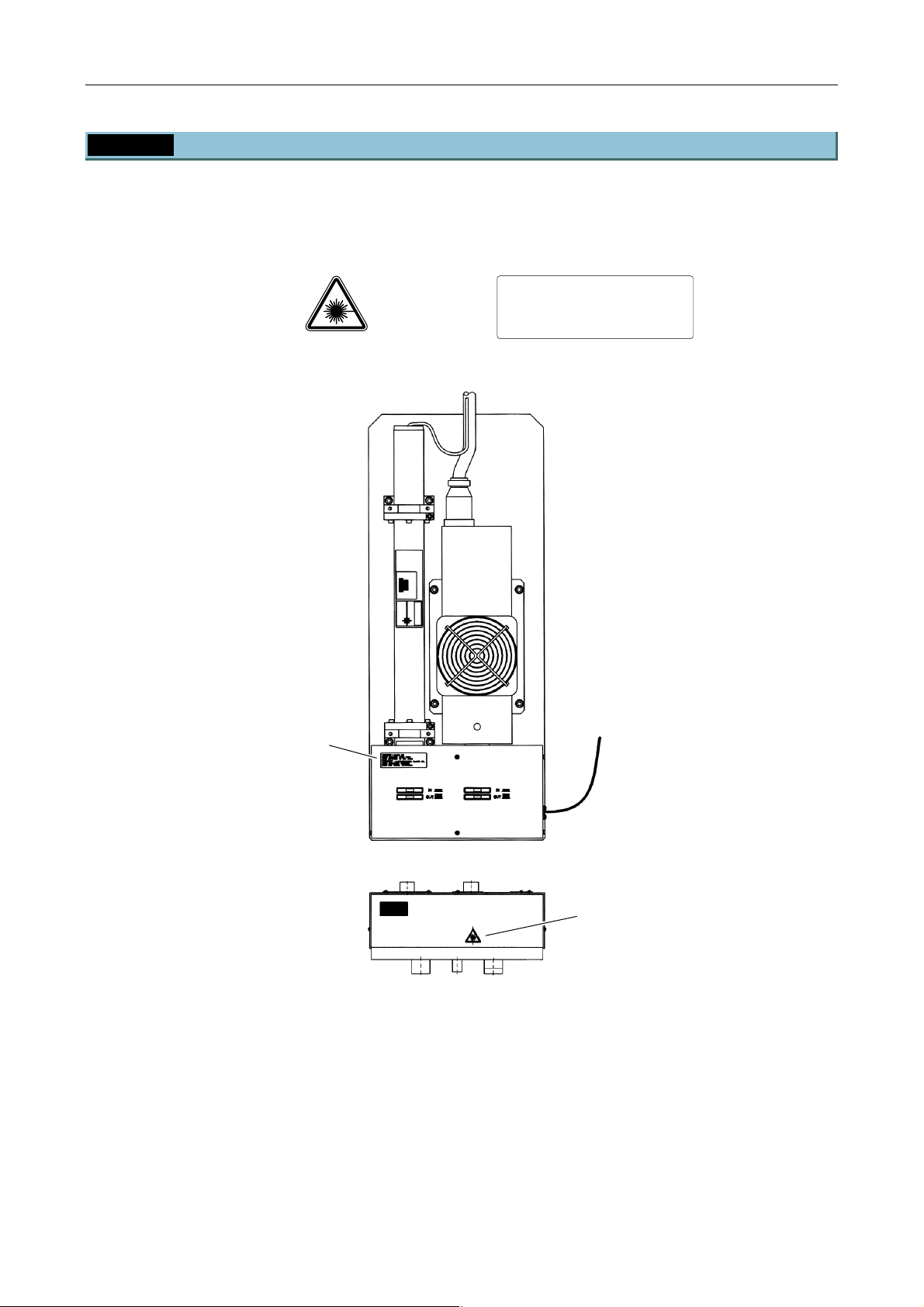
Chapter 1 System Configurations and Part Names
1.3 Safety Labels and Openings
1.3.4 C-LU2 Two-laser Unit
Make sure that the labels are affixed in place.
(1) IEC warning label -
laser hazard symbol
(6) IEC caution label -
Class 3B area
CAUTION
– CLASS 3B
RADIATION WHEN OPEN
LASER
AVOI D
EXPOSURE TO THE BEAM
VORSICHT
WENN
NICHT
– LASERSTRAHLUNG KLASSE 3B,
ABDECKUNG GEÖFFNET
DEM STRAHL AUSSETZEN
(6)
(1)
Figure 1.3-4
1-27
Page 42
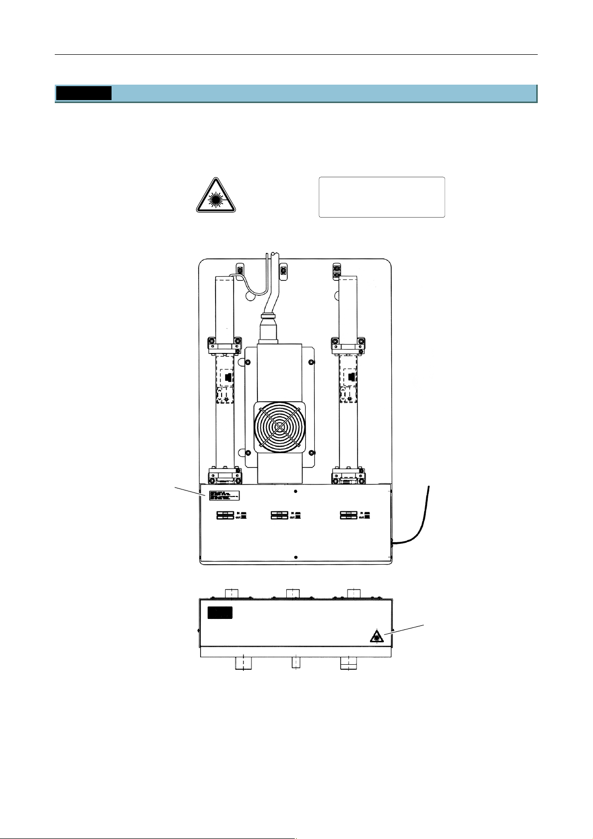
Chapter 1 System Configurations and Part Names
1.3 Safety Labels and Openings
1.3.5 C-LU3 Three-laser Unit
Make sure that the labels are affixed in place.
(1) IEC warning label -
laser hazard symbol
(6) IEC caution label -
Class 3B area
CAUTION
– CLASS 3B
RADIATION WHEN OPEN
LASER
AVOI D
EXPOSURE TO THE BEAM
VORSICHT
WENN
NICHT
– LASERSTRAHLUNG KLASSE 3B,
ABDECKUNG GEÖFFNET
DEM STRAHL AUSSETZEN
(6)
(1)
Figure 1.3-5
1-28
Page 43
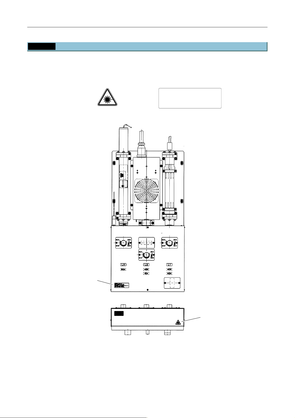
Chapter 1 System Configurations and Part Names
1.3 Safety Labels and Openings
1.3.6 C-LU3EX Three-laser Unit EX
Make sure that the labels are affixed in place.
(1) IEC warning label -
laser hazard symbol
(6) IEC caution label -
Class 3B area
CAUTION
– CLASS 3B
RADIATION WHEN OPEN
LASER
AVOI D
EXPOSURE TO THE BEAM
VORSICHT
WENN
NICHT
– LASERSTRAHLUNG KLASSE 3B,
ABDECKUNG GEÖFFNET
DEM STRAHL AUSSETZEN
(6)
(1)
Figure 1.3-6
1-29
Page 44
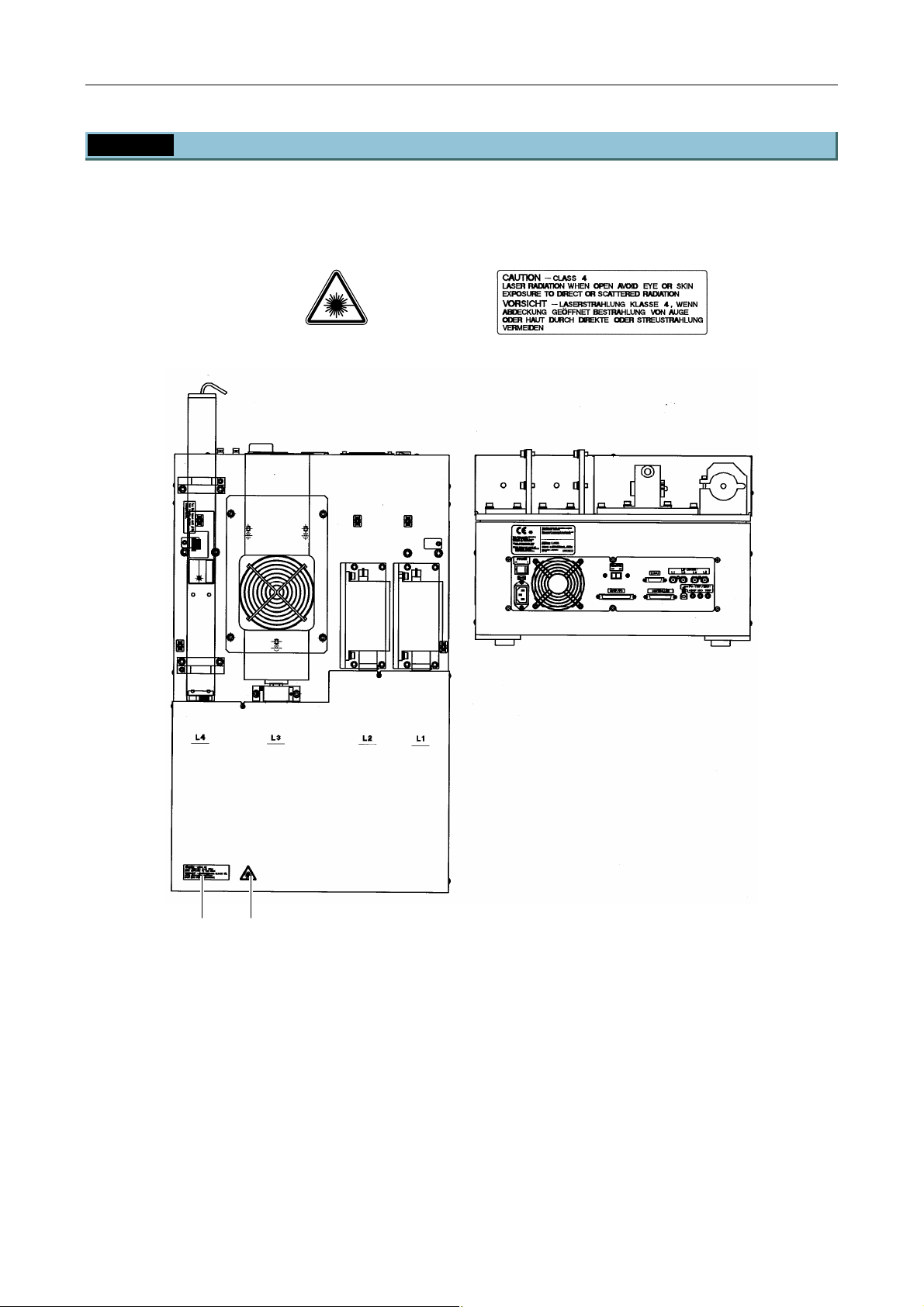
Chapter 1 System Configurations and Part Names
1.3 Safety Labels and Openings
1.3.7 LU4A Four-laser Module A
Make sure that the labels are affixed in place.
(1) IEC warning label -
laser hazard symbol
(12) IEC caution label - Class 4
area
(12)* (1)
Figure 1.3-7
* For the laser path inside the laser unit, see Section 1.2.1, “Laser Unit.”
1-30
Page 45
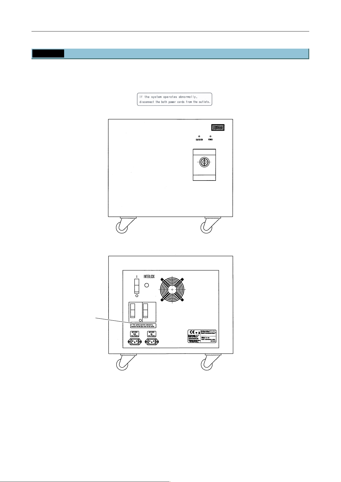
Chapter 1 System Configurations and Part Names
1.3 Safety Labels and Openings
1.3.8 LU-LR Four-laser PS Rack
Make sure that the label is affixed in place.
(11) Caution label
(Front view)
(11)
(Rear view)
Figure 1.3-8
1-31
Page 46
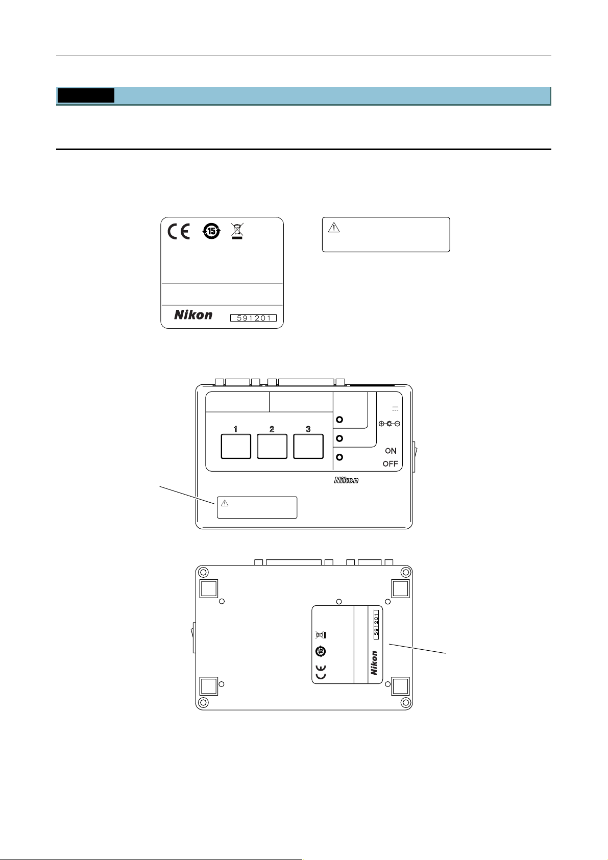
Chapter 1 System Configurations and Part Names
1.3 Safety Labels and Openings
1.3.9 TI-LUSU Shutter Unit
For the TIRF illuminator unit or the motorized TIRF illuminator unit
When used in combination with two-laser or three-laser unit
Make sure that the labels are affixed in place.
(4) Safety standard label (10) TI-TIRF special label
Exclusive use for TI-TIRF system
This device complies with Part 15 of the FCC Rules.
Operation is subject to the following two
conditions:
(1) this device may not cause harmful interference,
and
(2) this device must accept any interference received,
including interference that may cause undesired
operation.
This Class A digital apparatus complies with Canadian
ICES-003.
Cet appareil numérique de la classe A est confirme
à la norme NMB-003 du Canada.
Don't use this unit with other systems.
(10)
MADE IN JAPAN
RS-232C LASER UNIT
LASER SHUTTER
Exclusive use for TI-TIRF system
Don't use this unit with other systems.
(Top view)
SAFETY
COVER
CLOSE
BINO
CLOSE
POWER
12V
TI-LUSU
INPUT
1A
(Bottom view)
Figure 1.3-9
1-32
operation.
Cet appareil numérique de la classe A est confirme
à la norme NMB-003 du Canada.
This Class A digital apparatus complies with Canadian
ICES-003.
MADE IN JAPAN
including interference that may cause undesired
This device complies with Part 15 of the FCC Rules.
Operation is subject to the following two
conditions:
(1)this device may not cause harmful interference,
and
(2)this device must accept any interference received,
(4)
Page 47
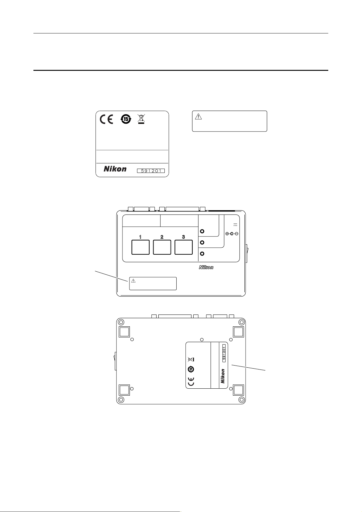
Chapter 1 System Configurations and Part Names
1.3 Safety Labels and Openings
For the photo activation illuminator unit
When used in combination with two-laser or three-laser unit
Make sure that the labels are affixed in place.
(4) Safety standard label (10) TI-PAU special label
Exclusive use for TI-PAU system
This device complies with Part 15 of the FCC Rules.
Operation is subject to the following two
conditions:
(1) this device may not cause harmful interference,
and
(2) this device must accept any interference received,
including interference that may cause undesired
operation.
This Class A digital apparatus complies with Canadian
ICES-003.
Cet appareil numérique de la classe A est confirme
à la norme NMB-003 du Canada.
Don't use this unit with other systems.
(10)
MADE IN JAPAN
RS-232C LASER UNIT
LASER SHUTTER
Exclusive use for TI-PAU system
Don't use this unit with other systems.
(Top view)
SAFETY
COVER
CLOSE
BINO
CLOSE
POWER
12V
TI-LUSU
INPUT
1A
ON
OFF
(Bottom view)
Figure 1.3-10
1-33
operation.
Cet appareil numérique de la classe A est confirme
à la norme NMB-003 du Canada.
This Class A digital apparatus complies with Canadian
ICES-003.
MADE IN JAPAN
including interference that may cause undesired
This device complies with Part 15 of the FCC Rules.
Operation is subject to the following two
conditions:
(1)this device may not cause harmful interference,
and
(2)this device must accept any interference received,
(4)
Page 48
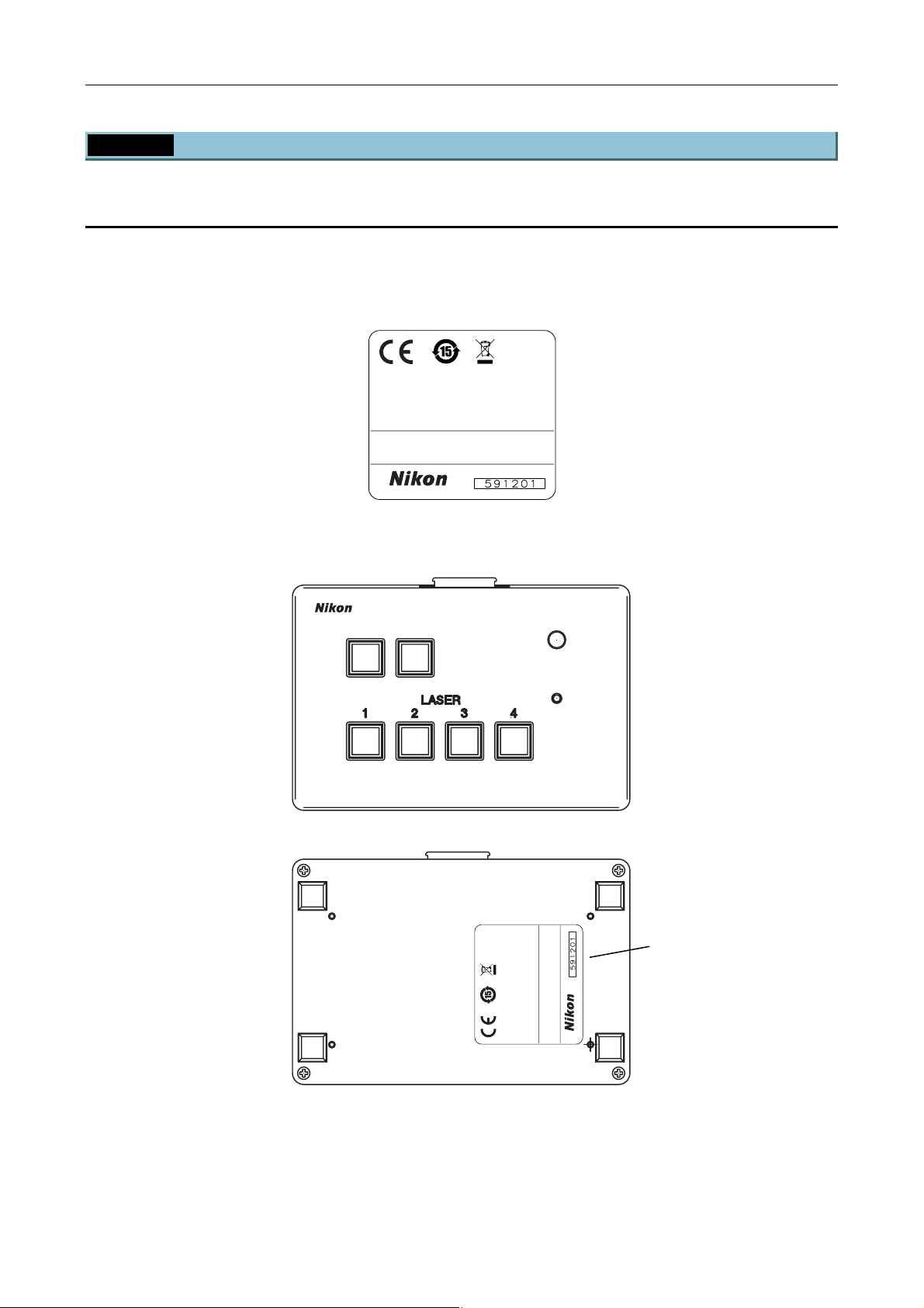
Chapter 1 System Configurations and Part Names
1.3 Safety Labels and Openings
1.3.10 TI-LU4SU Shutter Unit LU4
For the TIRF illuminator unit or the motorized TIRF illuminator unit
When used with four-laser module A
Make sure that the label is affixed in place.
(4) Safety standard label
This device complies with Part 15 of the FCC Rules.
Operation is subject to the following two
conditions:
(1) this device may not cause harmful interference,
and
(2) this device must accept any interference received,
including interference that may cause undesired
operation.
This Class A digital apparatus complies with Canadian
ICES-003.
Cet appareil numérique de la classe A est confirme
à la norme NMB-003 du Canada.
MADE IN JAPAN
TI-LU4SU
(Top view)
LASER
EMISSION
POWER
(4)
operation.
Cet appareil numérique de la classe A est confirme
This Class A digital apparatus complies with Canadian
ICES-003.
à la norme NMB-003 du Canada.
MADE IN JAPAN
This device complies with Part 15 of the FCC Ru les.
Operation is subject to the following two
conditions:
(1) this dev ice may not cause harmful interference,
and
(2) this dev ice must accept any interference received,
including interference that may cause undesired
(Bottom view)
Figure 1.3-11
1-34
Page 49
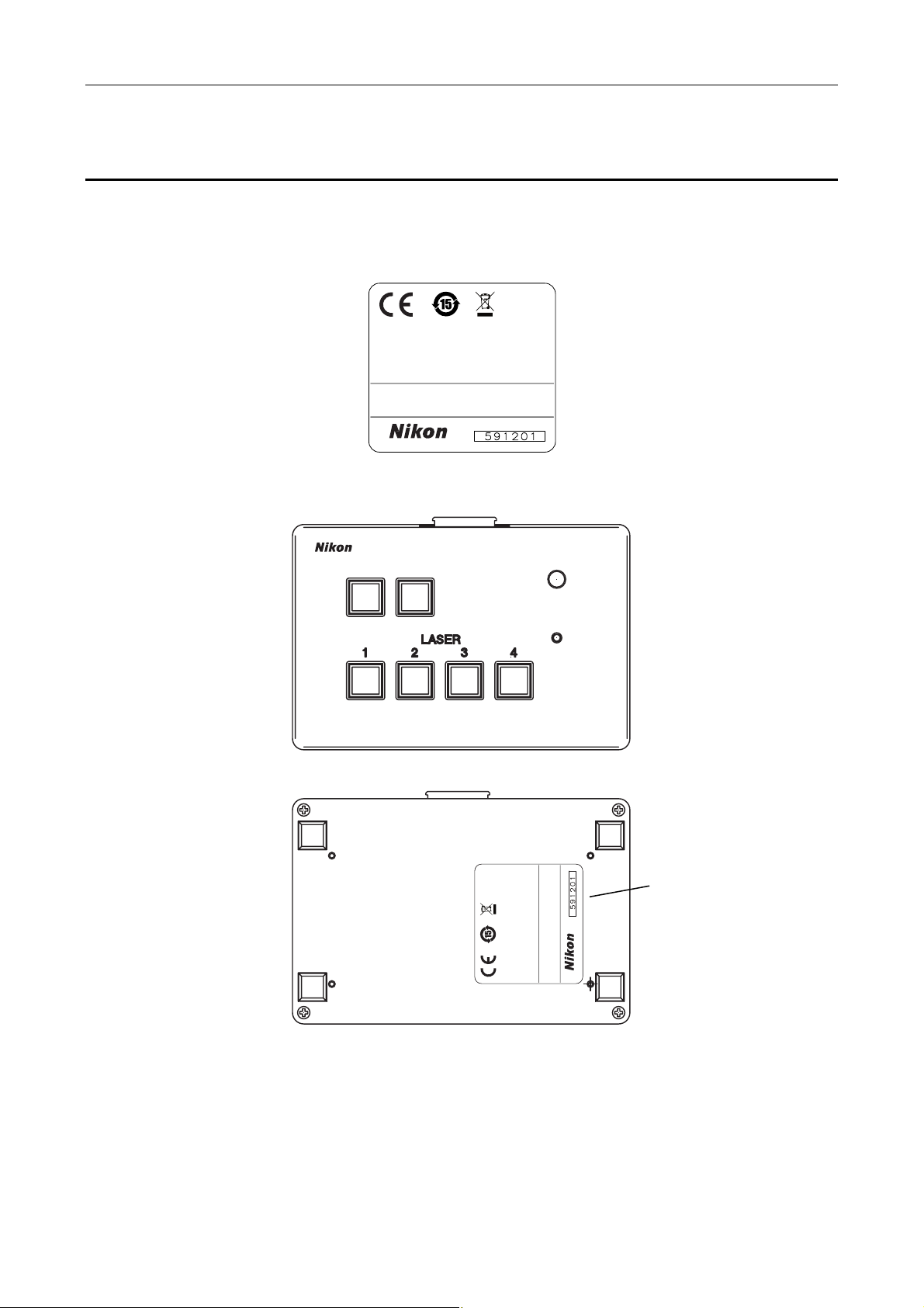
Chapter 1 System Configurations and Part Names
1.3 Safety Labels and Openings
For the photo activation illuminator unit
When used with four-laser module A
Make sure that the label is affixed in place.
(4) Safety standard label
This device complies with Part 15 of the FCC Rules.
Operation is subject to the following two
conditions:
(1) this device may not cause harmful interference,
and
(2) this device must accept any interference received,
including interference that may cause undesired
operation.
This Class A digital apparatus complies with Canadian
ICES-003.
Cet appareil numérique de la classe A est confirme
à la norme NMB-003 du Canada.
MADE IN JAPAN
TI-LU4SU
LASER
EMISSION
POWER
(Top view)
(4)
operation.
Cet appareil numérique de la classe A est confirme
This Class A digital apparatus complies with Canadian
ICES-003.
à la norme NMB-003 du Canada.
MADE IN JAPAN
This device complies with Part 15 of the FCC Ru les.
Operation is subject to the following two
conditions:
(1) this dev ice may not cause harmful interference,
and
(2) this dev ice must accept any interference received,
including interference that may cause undesired
(Bottom view)
Figure 1.3-12
1-35
Page 50
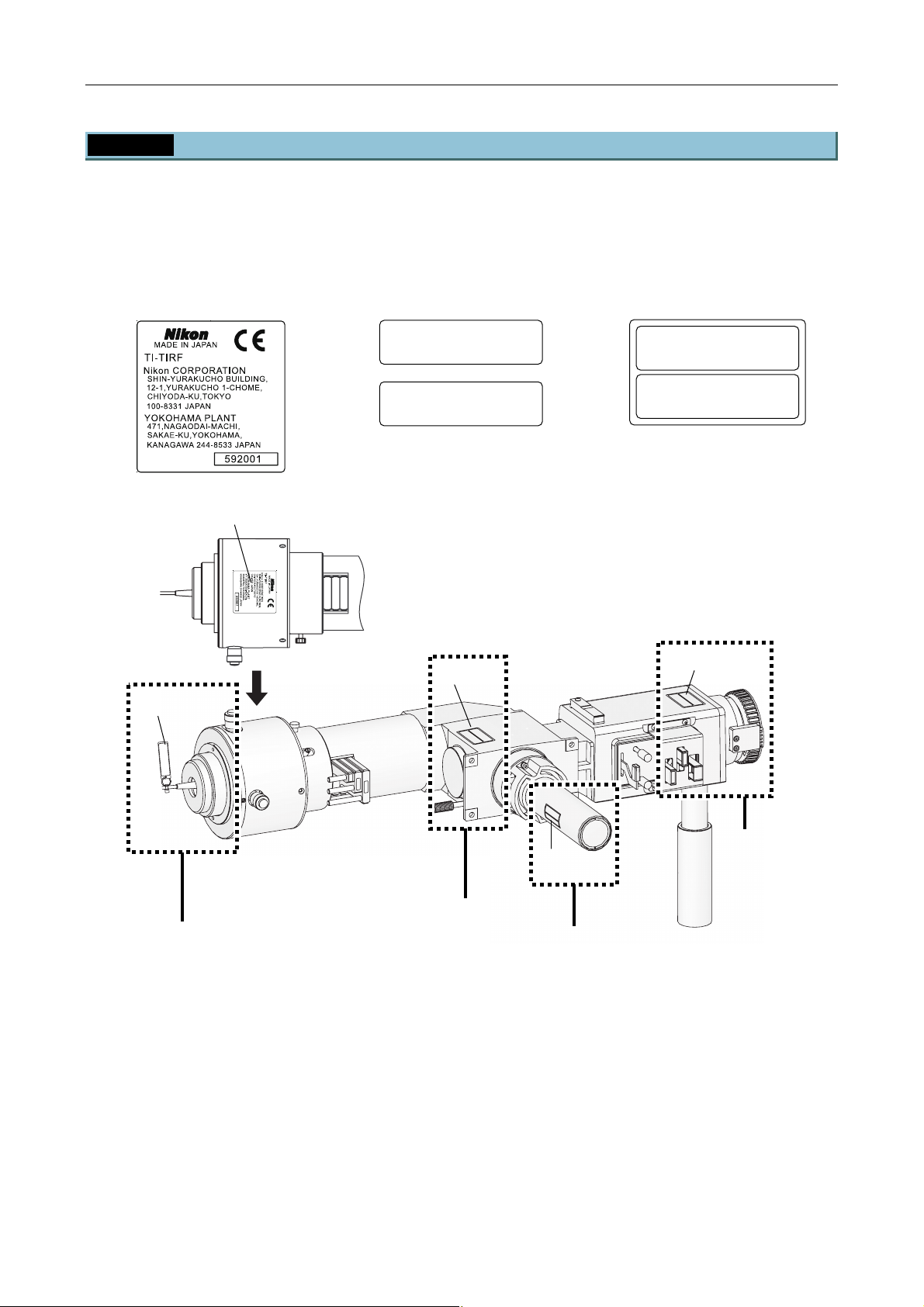
Chapter 1 System Configurations and Part Names
1.3 Safety Labels and Openings
1.3.11 TI-TIRF TIRF Illuminator Unit
Make sure that the labels are affixed in place.
This system has four openings, A to D, as shown below. Make sure that the following labels are affixed near
each of the openings.
(3) Model name and serial
number label
(5) IEC caution label -
Class 3B area
(7) IEC caution label -
Class 3B area
CAUTION – CLASS 3B
LASER RADIATION WHEN OPEN
AVOID EXPOSURE TO THE BEAM
–
VORSICHT
KLASSE 3B,
WENN ABDECKUNG GEÖFFNET
NICHT DEM STRAHL AUSSETZEN
LASERSTRAHLUNG
CAUTION – CLASS 3B
LASER RADIATION WHEN OPEN
AVOID EXPOSURE TO THE BEAM
–
VORSICHT
KLASSE 3B,
WENN ABDECKUNG GEÖFFNET
NICHT DEM STRAHL AUSSETZEN
LASERSTRAHLUNG
(5)
M
N
A
E
E
P
B
O
E
N
H
E
T
H
O
B
T
W
3
E
N
S
R
S
IO
U
A
T
L
S
IA
O
C
D
P
–
A
X
N
R
E
R
IO
ID
E
T
O
S
U
V
A
A
A
L
C
(3)
(7)
(7)
G
AUSSETZEN
HE BEAM
N OPEN
RSTRAHLUN
HE
RAHL
TO T
LASE
–
3B,
ABDECKUNG GEÖFFNET
CLASS 3B
–
NICHT DEM ST
WENN
ID EXPOSURE
KLASSE
VORSICHT
AVO
LASER RADIATION W
CAUTION
C
L
A
A
A
U
S
V
T
E
O
I
V
O
R
K
ID
O
N
W
L
R
R
E
A
N
–
S
E
A
S
IC
X
C
IC
N
D
S
P
H
N
L
I
H
E
A
O
A
T
T
T
A
S
D
S
3
IO
–
B
U
S
B
E
D
L
R
N
,
3
M
E
A
E
W
B
S
C
S
T
K
T
E
H
O
U
R
R
E
N
A
T
S
N
H
H
G
T
O
R
L
E
G
P
A
A
B
E
H
U
E
E
N
L
A
S
U
Ö
S
M
N
F
E
F
G
T
N
Z
E
E
T
N
.
S
.
N
D
2
N
N
D
D
8
6
1
C
A
U
T
I
LASER RADIA
O
N
–
A
C
VO
L
A
ID
S
E
TION W
S
X
PO
3
B
S
HEN OPE
U
V
R
O
E
R
T
S
K
O
I
L
C
T
AS
W
H
N
H
T
E
E
S
N
N
B
–
E
I
N
C
L
EA
H
3
A
A
T
M
B,
S
B
D
D
E
E
E
R
M
C
S
K
S
T
U
T
R
N
R
A
G
A
H
H
L
L
G
U
A
E
N
U
Ö
G
S
F
S
F
E
N
T
E
Z
T
E
N
A
R
E
FILT
8
D
N
4
D
N
N
D
8
N
D
4
D
(7)
B
A
C
Figure 1.3-13
1-36
Page 51
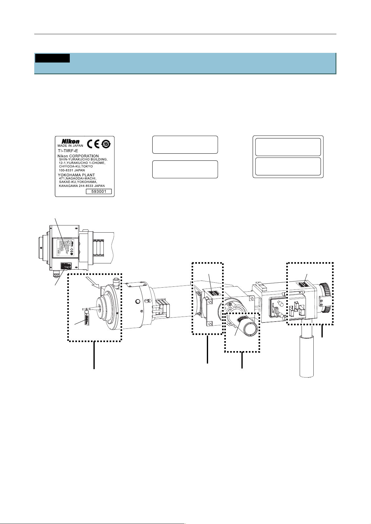
Chapter 1 System Configurations and Part Names
1.3 Safety Labels and Openings
1.3.12 TI-TIRF-E Motorized TIRF Illuminator Unit ― For Normal Microscopy
(Except N-STORM)
Make sure that the labels are affixed in place.
This system has four openings, A to D, as shown below. Make sure that the following labels are affixed near
each of the openings.
(3) Model name and serial
number label
(5) IEC caution label -
Class 3B area
(7) IEC caution label -
Class 3B area
CAUTION – CLASS 3B
LASER RADIATION WHEN OPEN
AVOID EXPOSURE TO THE BEAM
–
VORSICHT
KLASSE 3B,
WENN ABDECKUNG GEÖFFNET
NICHT DEM STRAHL AUSSETZEN
LASERSTRAHLUNG
CAUTION – CLASS 3B
LASER RADIATION WHEN OPEN
AVOID EXPOSURE TO THE BEAM
–
VORSICHT
KLASSE 3B,
WENN ABDECKUNG GEÖFFNET
NICHT DEM STRAHL AUSSETZEN
LASERSTRAHLUNG
(3)
Back view
(7)
(7)(7)
(5)
(7)
A
B
C
D
Figure 1.3-14
1-37
Page 52
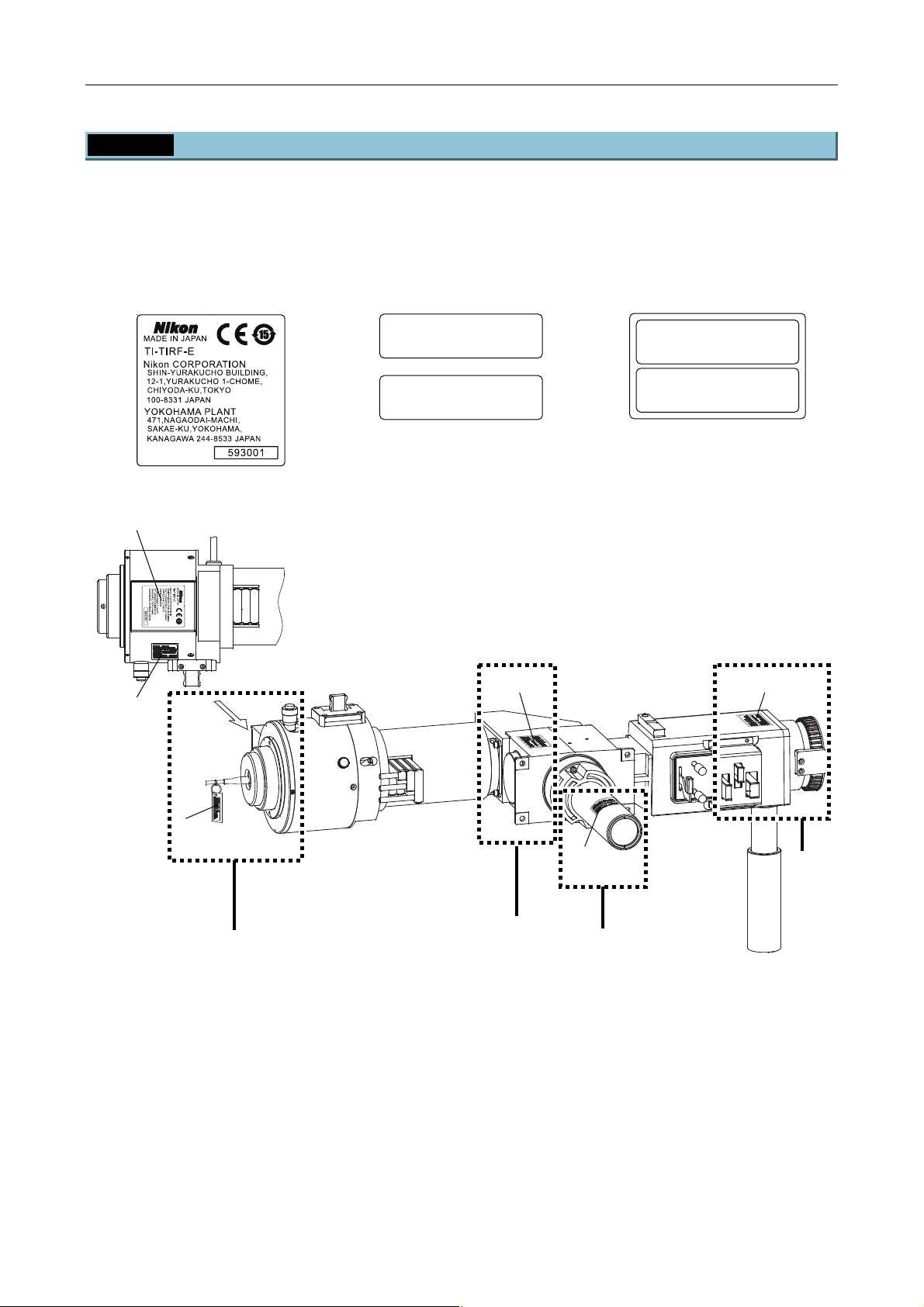
Chapter 1 System Configurations and Part Names
1.3 Safety Labels and Openings
1.3.13 TI-TIRF-E Motorized TIRF Illuminator Unit ― For N-STORM Microscopy
Make sure that the labels are affixed in place.
This system has four openings, A to D, as shown below. Make sure that the following labels are affixed near
each of the openings.
(3) Model name and serial
number label
(5) IEC caution label -
Class 3B area
(7) IEC caution label -
Class 3B area
CAUTION – CLASS 3B
LASER RADIATION WHEN OPEN
AVOID EXPOSURE TO THE BEAM
–
VORSICHT
KLASSE 3B,
WENN ABDECKUNG GEÖFFNET
NICHT DEM STRAHL AUSSETZEN
LASERSTRAHLUNG
CAUTION – CLASS 3B
LASER RADIATION WHEN OPEN
AVOID EXPOSURE TO THE BEAM
–
VORSICHT
KLASSE 3B,
WENN ABDECKUNG GEÖFFNET
NICHT DEM STRAHL AUSSETZEN
LASERSTRAHLUNG
(3)
Back view
(7)(7)
(7)
(5)
(7)
A
B
C
D
Figure 1.3-15
1-38
Page 53
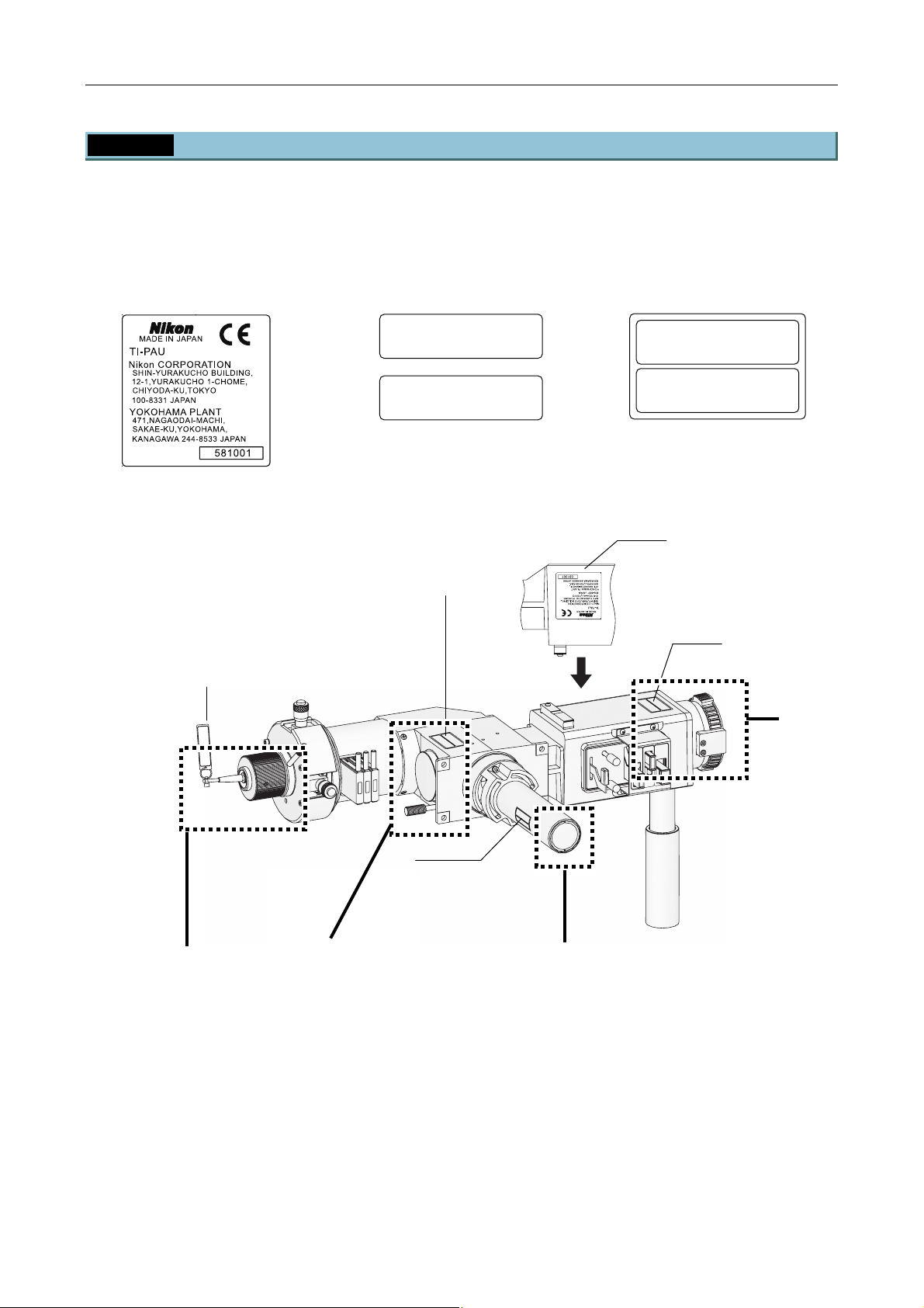
Chapter 1 System Configurations and Part Names
1.3 Safety Labels and Openings
1.3.14 TI-PAU Photo Activation Illuminator Unit
Make sure that the labels are affixed in place.
This system has four openings, A to D, as shown below. Make sure that the following labels are affixed near
each of the openings.
(3) Model name and serial
number label
(5) IEC caution label -
Class 3B area
(7) IEC caution label -
Class 3B area
CAUTION – CLASS 3B
LASER RADIATION WHEN OPEN
AVOID EXPOSURE TO THE BEAM
–
VORSICHT
KLASSE 3B,
WENN ABDECKUNG GEÖFFNET
NICHT DEM STRAHL AUSSETZEN
LASERSTRAHLUNG
CAUTION – CLASS 3B
LASER RADIATION WHEN OPEN
AVOID EXPOSURE TO THE BEAM
–
VORSICHT
KLASSE 3B,
WENN ABDECKUNG GEÖFFNET
NICHT DEM STRAHL AUSSETZEN
LASERSTRAHLUNG
(3)
(7)
Back
(7)
(5)
N
T
E
E
Z
N
T
G
F
E
N
M
F
S
A
U
Ö
N
L
S
E
E
E
H
U
B
P
G
A
A
E
O
R
L
H
T
N
G
H
S
T
E
N
A
R
O
H
U
R
E
T
K
T
B
S
W
E
C
S
A
3
N
E
R
,
L
M
S
D
U
IO
E
B
S
–
B
S
T
3
A
A
D
T
A
O
L
I
T
H
E
P
C
D
N
H
S
X
IC
A
N
C
–
S
E
I
S
E
A
R
N
R
N
D
L
W
I
R
O
K
IO
E
O
V
T
S
V
U
A
A
A
L
C
N
OPE
N
N WHE
CLASS 3B
–
N
ID EXPOSURE TO THE BEAM
AVO
LASER RADIATIO
CAUTIO
I
N
I
N
ND2
N
N
N
D
D
D
16
8
2
VORSICHT
KLASSE
WENN
NICHT DEM STRAHL AUSSETZEN
ABDECKUNG GEÖFFNET
AVO
3B,
–
LASERSTRAHLUNG
LASER RADIA
ID EXPOSURE
CAUTION
–
CLASS 3B
TION WHEN OPEN
TO THE BEAM
C
A
U
T
IO
LASER RAD
N
–
C
AVO
L
A
ID EXPOSURE
IATION W
S
S
3
B
HEN OPEN
V
O
R
TO T
S
K
I
L
C
A
W
H
HE BEAM
S
T
E
S
N
N
–
E
I
N
C
L
H
3
A
A
T
B
S
B
D
D
E
,
E
E
R
M
C
S
K
S
T
U
T
R
N
R
A
G
A
H
H
L
L
G
U
A
E
N
U
Ö
G
S
F
S
F
E
N
T
E
Z
T
E
N
ND8
ND4 FILTER
N
D
S.
A.
8
N
D
4
D
(7)
A
B
C
Figure 1.3-16
1-39
Page 54
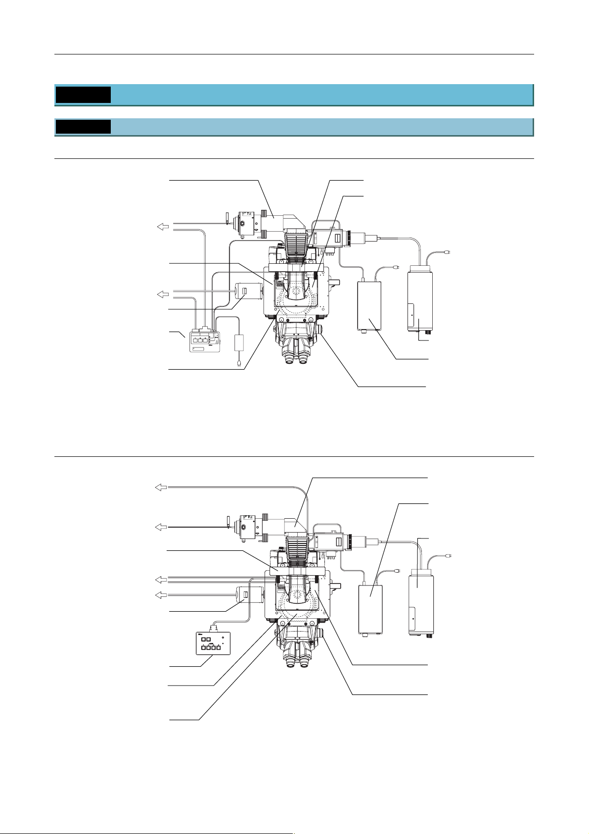
Chapter 1 System Configurations and Part Names
r
1.4 Name of Each Part
1.4 Name of Each Part
1.4.1 TIRF Illuminator Unit and Ti-U System
When used with two-laser or three laser-unit
TIRF illuminator unit
CLASS 3B
–
LASER RADIATION WHEN OPEN
AVOID EXPOSURE TO THE BEAM
CAUTION
To laser unit
Laser safety cove
To PC
TV camera (video camera)
TI-LUSU
shutter unit
Filter cube port cover retaining
RS-232C LASER UNIT
LASER SHUTTER
Exclusive use for TI-TIRF system
Don't use this unit with other systems.
INPUT
12V
SAFETY
1A
COVER
CLOSE
BINO
CLOSE
POWER
TI-LUSU
plate (part of laser safety kit)
When used with four-laser module A
SER RADIATIO
OID EXPOSU
CLASS 3B LASE
AVOID EXPOSURE
LASER LIGHT IS EMITTE
OBJECTIVE APERT
FROM
Figure 1.4-1
Filter slider cover (part of laser safety kit)
TI-FLC epi-fl filter turret
LASERSTRAHLUNG
CLASS 3B
–
–
KLASSE 3B,
WENN ABDECKUNG GEÖFFNET
NICHT DEM STRAHL AUSSETZEN
LASER RADIATION WHEN OPEN
AVOID EXPOSURE TO THE BEAM
VORSICHT
CAUTION
HG fiber light source
Power supply device for the
diascopic illumination
Optical path selector knob
To laser unit
To laser unit
Filter slider cover
(part of laser safety kit)
To laser unit
To PC
TV camera (video camera)
TI-LU4SU shutter unit LU4
Filter cube port cover retaining
plate
(part of laser safety plate)
TI-FLC epi-fl filter turret
TI-LU4SU
TIRF illuminator unit
Power supply device for the
CLASS 3B
–
CAUTION
LASER RADIATION WHEN OPEN
AVOID EXPOSURE TO THE BEAM
LASERSTRAHLUNG
CLASS 3B
–
–
KLASSE 3B,
WENN ABDECKUNG GEÖFFNET
NICHT DEM STRAHL AUSSETZEN
LASER RADIATION WHEN OPEN
AVOID EXPOSURE TO THE BEAM
VORSICHT
CAUTION
SER RADIATIO
OID EXPOSU
CLASS 3B LASE
AVOID EXPOSURE
LASER LIGHT IS EMITTE
FROM
OBJECTIVE APERT
LASER
EMISSION
POWER
diascopic illumination
HG fiber light source
Laser safety cover
Optical path selector knob
Figure 1.4-2
1-40
Page 55
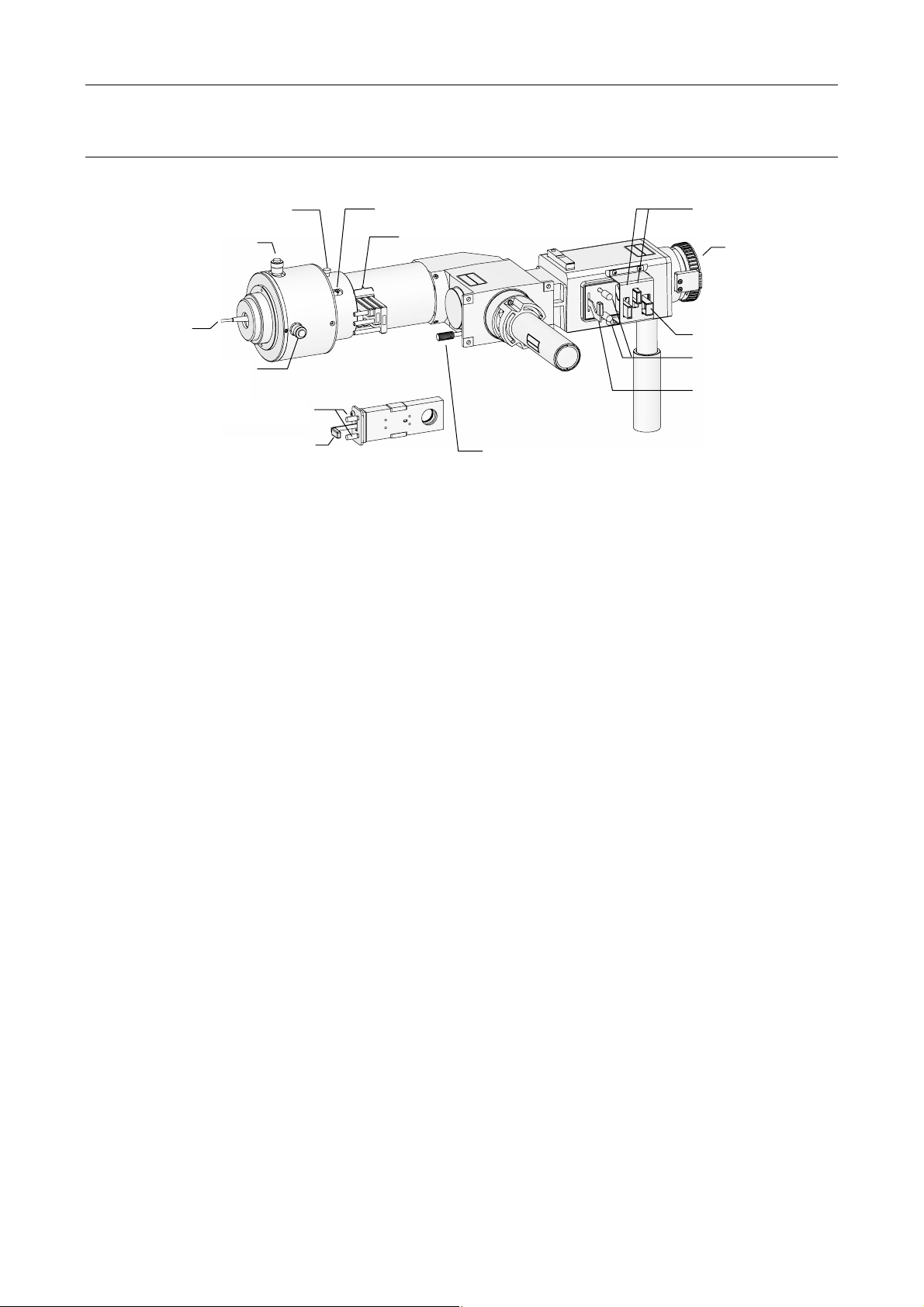
TI-TIRF illuminator unit
r
(7) Condenser lens locking screw
(3) Laser position adjustment knob
(for forward and backward
adjustment)
(1) Optical fibe
(2) Laser position adjustment knob
(for right and left adjustment)
(8) Field diaphragm centering screws
Chapter 1 System Configurations and Part Names
1.4 Name of Each Part
(6) Focal point adjustment knob
(4) ND filter sliders
N
D
2
N
N
D
D
8
16
VORSICHT
KLASSE 3B,
WENN ABDECKUNG GEFFNET
NICHT DEM STRAHL AUSSETZEN
CAUTION
LASER RADIATION WHEN OPEN
AVOID EXPOSURE TO THE BEAM
LASERSTRAHLUNG
CLASS 3B
ND4
S.
A.
N
D
4
CAUTI
LA
ON
S
ER
AVOI
R
CLASS 3B
ADIATION W
D EXPOSURE TO THE BEAM
H
V
EN OP
O
R
S
KLASS
I
C
E
WENN
H
N
T
NIC
E 3
LASE
HT
ABD
B,
D
EM STR
E
R
C
S
K
T
UNG
R
A
AHL A
H
G
LUNG
E
U
FFNE
S
SETZEN
T
(12) ND filter slider
FNET
F
AM
LUNG
E
H
A
E BE
R
AUSSETZEN
OPEN
L
T
N
RAH
SERS
WHE
3B
ST
N
LA
,
O
EM
ASS
D
ABDECKUNG G
L
C
N
SE 3B
ICHT
ADIATI
N
CHT
S
EXPOSURE TO TH
R
NI
RS
N
D
LA
WE
I
O
K
O
V
SER
UTIO
AV
LA
CA
FILTERND8
N
D
8
(14) Connector for the
HG fiber light
source adapter
(13) Excitation filter slider
(10) Aperture diaphragm
centering screws
(11) Aperture diaphragm
open/close lever
(9) Field diaphragm open/close lever
Parts used in the TIRF microscopy operation
(1) Optical fiber
(2) Laser position adjustment knob
(for right and left adjustment)
(3) Laser position adjustment knob
(for forward and backward adjustment)
(4) ND filter sliders
(5) Mirror switching lever
Push in: TIRF (60%) and Epi (40%)
Pull out: TIRF (100%)
(6) Focal point adjustment knob
(7) Condenser lens locking screw
(5) Mirror switching lever
Figure 1.4-3
Parts used in the epi-fl microscopy operation
(8) Field diaphragm centering screws
(9) Field diaphragm open/close lever
(10) Aperture diaphragm centering screws
(11) Aperture diaphragm open/close lever
(12) ND filter sliders
(13) Excitation filter slider
(14) Connector for the HG fiber light source
Push in: TIRF (60%) and Epi (40%)
Pull out: TIRF (100%)
adapter
1-41
Page 56
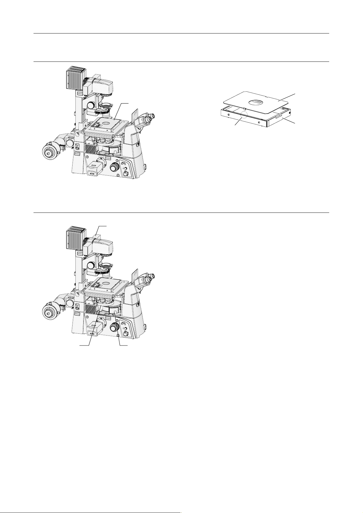
Laser safety cover
C
A
U
T
I
O
N
–
C
L
A
S
S
3
L
B
A
S
E
R
R
A
D
I
A
T
I
O
N
W
A
V
H
O
E
ID
N
O
E
X
P
P
E
O
N
S
U
R
E
T
O
T
H
E
B
E
A
M
V
O
R
S
I
C
H
T
–
L
A
S
E
K
R
L
A
S
S
T
R
S
E
A
H
3
L
B
U
,
N
G
W
E
N
N
A
B
D
E
C
K
U
N
N
G
I
C
H
T
G
D
E
Ö
E
M
F
F
S
N
T
E
R
T
A
H
L
A
U
S
S
E
T
Z
E
N
Chapter 1 System Configurations and Part Names
1.4 Name of Each Part
The laser safety cover prevents laser light from
leaking. If the laser safety cover is not attached, the
motorized shutters of the laser unit do not open.
Laser safety cover
BEAM
DUCT
E TO
PRO
TION
UR
E
R
DIA
U
D
T
E
R
T
T
E
I
P
M
ER RA
S 3B LASER
A
E
S
SURE
E
S
AS
I
V
I
L
T
AVOID EXPOS
T
CLA
C
H
E
G
EXPO
J
I
B
L
O
R
E
M
S
VOID
O
A
A
R
L
F
Safety interlock (both sides)
Figure 1.4-5
Upper cover
Body
C
A
U
T
I
O
N
–
C
L
A
S
S
3
L
A
B
S
E
R
R
A
D
IA
T
I
O
N
W
A
V
H
O
E
I
D
N
E
O
X
P
P
E
O
S
U
R
E
T
O
T
H
E
B
E
A
V
O
R
S
I
C
H
T
–
L
A
S
E
K
R
L
A
S
S
T
S
R
E
A
H
3
L
B
U
,
N
G
W
E
N
N
A
B
D
E
C
K
U
N
N
I
G
C
H
T
G
D
E
E
Ö
M
F
F
S
N
T
E
R
A
H
L
A
U
S
S
E
T
Z
E
Laser safety kit
C
A
U
T
I
O
N
–
L
A
S
E
R
R
A
A
V
O
I
D
E
X
V
O
R
S
I
C
H
T
K
L
A
S
S
E
3
W
E
N
N
A
B
N
I
C
H
T
D
E
C
A
U
T
I
O
N
–
C
L
A
S
S
L
3
A
B
S
E
R
R
A
D
I
A
T
I
O
N
W
A
V
H
O
E
I
D
N
E
O
X
P
P
E
O
S
U
R
E
T
O
T
H
E
B
E
A
V
O
R
S
I
C
H
T
–
L
A
S
E
K
R
L
A
S
S
T
S
R
E
A
H
3
L
B
U
,
N
G
W
E
N
N
A
B
D
E
C
K
U
N
N
I
G
C
H
T
G
D
E
E
Ö
M
F
F
S
N
T
E
R
A
H
L
A
U
S
S
E
T
Z
E
Protection plate
(for nosepiece)
N
M
T
N
Figure 1.4-4
C
L
A
S
S
3
B
D
I
A
T
I
O
N
W
H
E
N
O
P
P
E
O
N
S
U
R
E
T
O
T
H
E
B
E
A
M
–
L
A
S
E
R
S
T
R
A
H
L
B
U
,
N
G
D
E
C
K
U
N
G
G
E
Ö
M
F
F
S
N
T
E
R
T
A
H
L
A
U
S
S
E
T
Z
E
N
A
R
R
E
S
O
V
LA
A
N
M
T
N
Figure 1.4-6
A
V
O
ID
E
X
P
O
S
U
LASER
R
E
LIGHT
IS
FROM
EMITTED
THIS
C
A
APERTURE
U
T
I
O
N
–
C
L
A
S
S
3
L
B
A
S
E
R
R
A
D
IA
T
I
O
N
W
A
V
H
O
E
I
N
D
O
E
P
X
E
P
N
O
S
U
R
E
T
O
T
H
E
B
E
A
M
V
O
R
S
I
C
H
T
–
L
A
S
E
K
R
L
S
A
T
S
R
S
A
E
H
3
L
U
B
N
,
G
W
E
N
N
A
B
D
E
C
K
U
N
N
G
I
C
H
G
T
E
D
Ö
E
F
M
F
S
N
T
E
R
T
A
H
L
A
U
S
S
E
T
Z
E
N
Filter slider cover
AM
CT
U
BE
D
O
O
R
T
N
E
P
IO
R
R
T
E
SU
IA
E
S
R
D
O
U
D
P
LA
T
E
X
R
T
E
T
E
I
E
3B
P
R
M
S
A
ID
U
E
S
S
E
S
A
V
I
O
I
T
P
T
CL
C
H
E
G
EX
J
I
B
L
O
ID
R
O
E
M
S
V
O
A
A
R
L
F
A
V
O
ID
E
X
P
O
S
U
LASER
R
E
LIGHT
IS
FROM
EMITTED
THIS
C
A
APERTURE
U
T
I
O
N
–
C
L
A
S
S
3
L
B
A
S
E
R
R
A
D
I
A
T
I
O
N
W
A
V
H
O
E
I
N
D
O
E
P
X
E
P
N
O
S
U
R
E
T
O
T
H
E
B
E
A
M
V
O
R
S
I
C
H
T
–
L
A
S
E
K
R
L
S
A
T
S
R
S
A
E
H
3
L
U
B
N
,
G
W
E
N
N
A
B
D
E
C
K
U
N
N
G
I
C
H
G
T
E
D
Ö
E
F
M
F
S
N
T
E
R
T
A
H
L
A
U
S
S
E
T
Z
E
N
ON
OFF
6V30W
12V100W
MAX.
ON
OFF
6V30W
12V100W
MAX.
Filter cube port cover
retaining plate
* If the safety interlock part is touched or gotten wet,
misoperation may occur.
The laser safety kit is composed of the filter slider
cover, protection plate, filter cube port fixed plate, and
safety labels.
Before using the product, check that the part shown
in the left figure is attached.
* For the types and positions of safety labels, see
Section 1.3.1, “Ti-U Microscope Body.”
1-42
Page 57
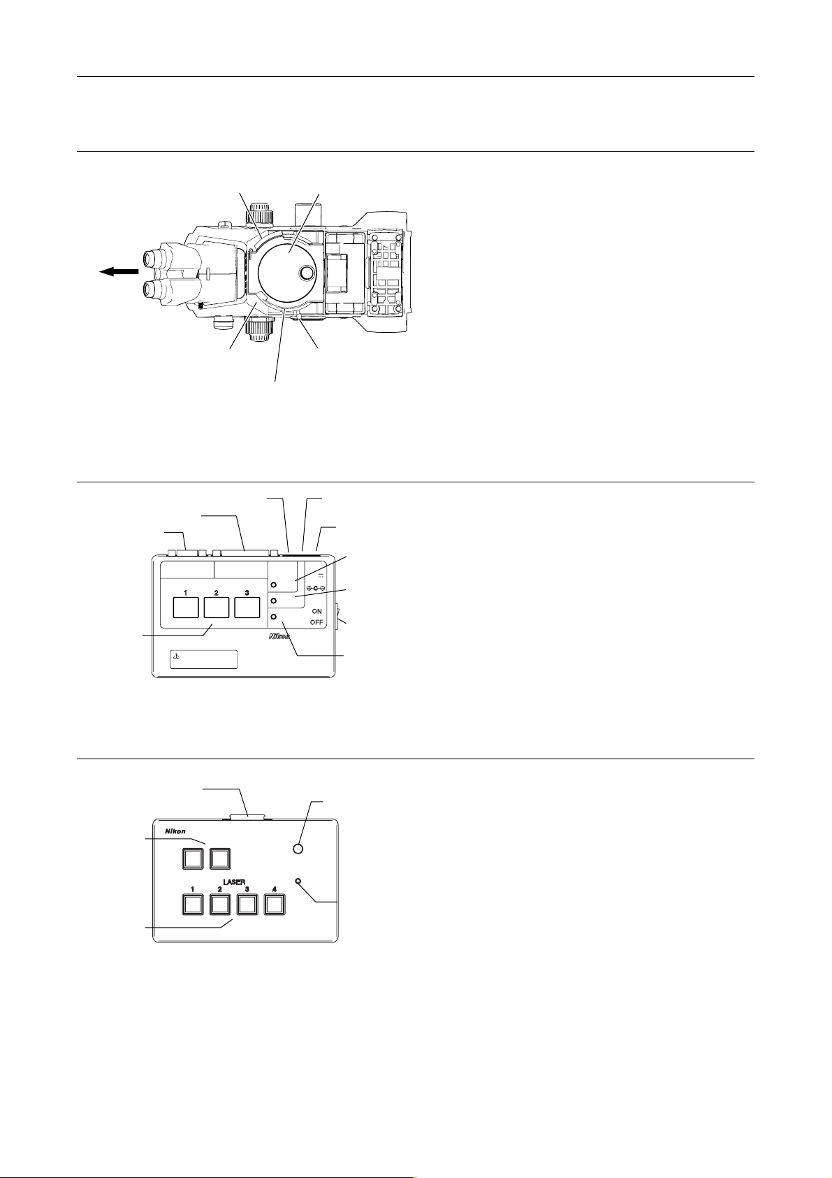
TI-FLC epi-fl filter turret
A
r
r
r
r
Chapter 1 System Configurations and Part Names
1.4 Name of Each Part
Filter cube port
(and its cover)
Front
Filter cube address and
name on the optical path
TI-LUSU shutter unit
Safety cover signal connector
Laser unit connecto
Serial IF connecto
RS-232C LASER UNIT
Laser shutter
switch / indicato
Exclusive use for TI-TIRF system
Don't use this unit with other systems.
Figure 1.4-7
LASER SHUTTER
Figure 1.4-8
TI-FLC epi-fl
filter turret
Shutter lever
(O: open, C: close)
Filter cube rotation control
Eyepiece optical path
TI-LUSU
INPUT
12V
1A
signal connector
C adapter
connector
Safety cover
close lamp
Eyepiece optical
path closed lamp
Power switch
SAFETY
COVER
CLOSE
BINO
CLOSE
POWER
Power lamp
The epi-fl filter turret is used to select an excitation
method by rotating the turret to change filter cubes
including a dichroic mirror.
The shutter unit controls motorized shutters in the
laser unit.
Use this unit in combination with the C-LU2, C-LU3 or
C-LU3EX laser unit.
TI-LU4SU shutter unit LU4
Laser unit connecto
Option switch
Laser shutter
switch
TI-LU4SU
Figure 1.4-9
Indicator lamp
LASER
EMISSION
POWER
Power lamp
The shutter unit controls motorized shutters in the
laser unit.
Use this unit in combination with the LU4A laser
unit.
If the safety interlock functions, all the shutters are
closed, and the lamp turns off.
To unlock the safety interlock, solve what caused
the safety interlock being locked, then cancel the
safety interlock from the software.
1-43
Page 58
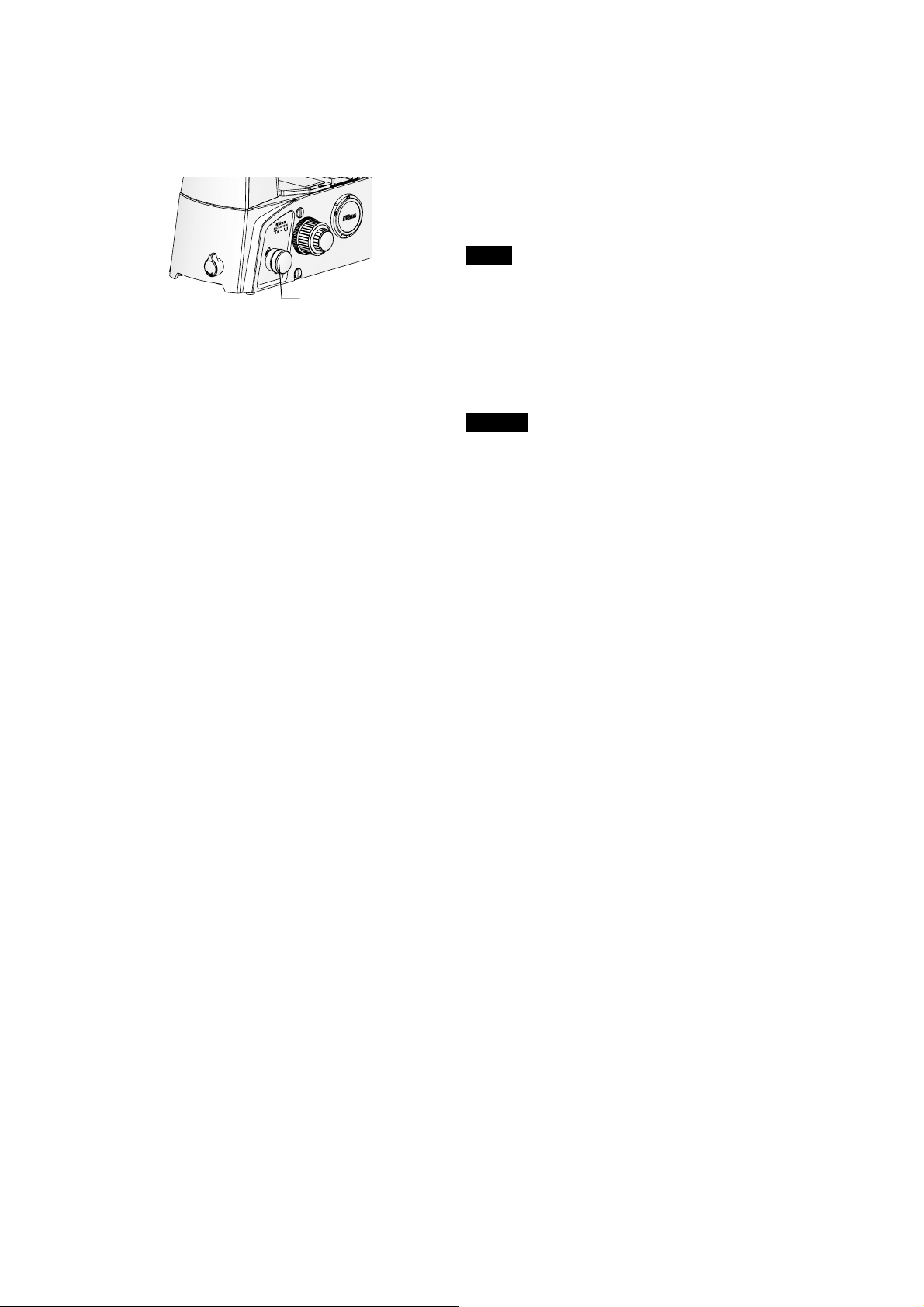
Chapter 1 System Configurations and Part Names
1.4 Name of Each Part
Optical path selector knob (on the microscope body)
The laser shutter does not open when the eyepiece
route of the optical path (“EYE”) is selected.
PORT
Ti-U *
PORT dial
(optical path selector knob)
Figure 1.4-10
EYE Observation port 100%
R Right port 100%
AUX Auxiliary port
(Observation/left port = 20:80)
(Observation/right port = 20:80)
L Left port 100%
Ti-U/B
EYE Observation port 100%
R Right port 100%
B Bottom port 100%
L Left port 100%
* The Ti-U is also available with an optical-path
splitter prism preinstalled at the auxiliary port. The
light intensity ratio of visual observation to left port
is 20 to 80.
In this case, set the optical path selector knob as
follows:
EYE Observation port 100%
R Right port 100%
L80 Visual observation/left port = 20:80
L Left port 100%
1-44
Page 59
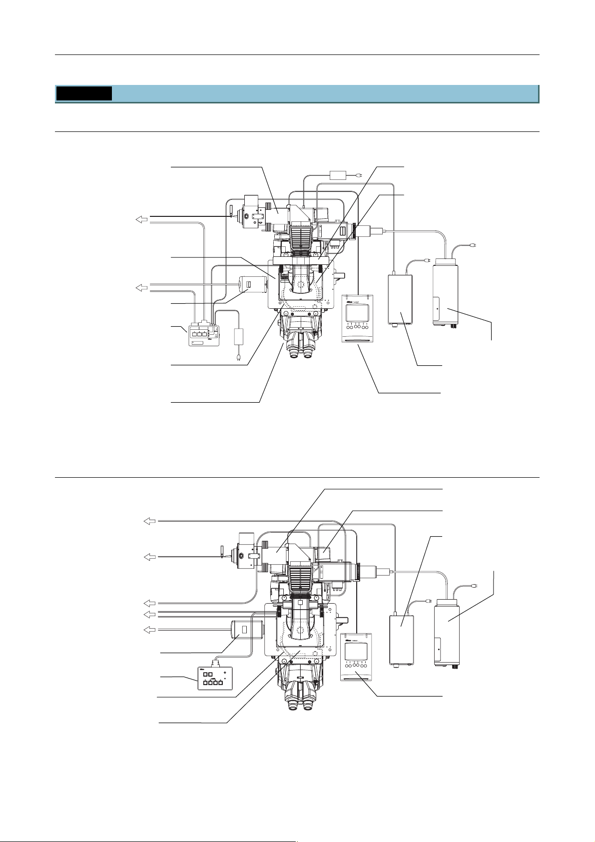
Chapter 1 System Configurations and Part Names
r
(
(
)
1.4 Name of Each Part
1.4.2 Motorized TIRF Illuminator Unit and Ti-E System
When used in combination with two-laser or three-laser unit
Motorized TIRF illuminator unit
CLASS 3B
CLASS 3B
–
–
CAUTION
LASER RADIATION WHEN OPEN
AVOID EXPOSURE TO THE BEAM
CAUTION
LASER RADIATION WHEN OPEN
To laser unit
Laser safety cove
To PC
TV camera (video camera)
TI-LUSU
shutter unit
Filter cube port cover retaining
.
plate
part of laser safety kit)
Optical path selector switch
(front panel)
RS-232C LASER UNIT
LASER SHUTTER
Exclusive use for TI-TIRF system
Don't use this unit with other systems.
AVOID EXPOSURE TO THE BEAM
LASERSTRAHLUNG
LASERSTRAHLUNG
CLASS 3B
CLASS 3B
–
–
–
–
CAUTION
KLASSE 3B,
WENN ABDECKUNG GEÖFFNET
NICHT DEM STRAHL AUSSETZEN
LASER RADIATION WHEN OPEN
AVOID EXPOSURE TO THE BEAM
VORSICHT
CAUTION
LASER RADIATION WHEN OPEN
AVOID EXPOSURE TO THE BEAM
VORSICHT
KLASSE 3B,
WENN ABDECKUNG GEÖFFNET
NICHT DEM STRAHL AUSSETZEN
SER RADIATIO
SER RADIATIO
OID EXPOSU
OID EXPOSU
CLASS 3B LASE
CLASS 3B LASE
AVOID EXPOSURE
AVOID EXPOSURE
LASER LIGHT IS EMITTE
LASER LIGHT IS EMITTE
FROM OBJECTIVE APERT
FROM
OBJECTIVE APERT
INPUT
12V
SAFETY
1A
COVER
CLOSE
BINO
CLOSE
POWER
TI-LUSU
Figure 1.4-11
Filter slider cover
(part of laser safety kit)
TI-FLC-E or TI-FLC-E/HQ
motorized epi-fl filter turret, with
Protection plate (part of laser safety kit)
HG fiber light source
Power supply device for
the diascopic illumination
TI-RCP remote control pad
When used with four-laser module A
To laser unit
CLASS 3B
CLASS 3B
–
–
CAUTION
LASER RADIATION WHEN OPEN
AVOID EXPOSURE TO THE BEAM
CAUTION
LASER RADIATION WHEN OPEN
TI-LU4SU
AVOID EXPOSURE TO THE BEAM
LASER
EMISSION
POWER
To laser unit
To PC
To laser unit
To PC
TV camera (video camera)
TI-LU4SU shutter unit LU4
Filter cube port cover
retaining plate
TI-FLC-E/HQ motor epi-fl
filter turret,
with protection plate
(part of laser safety kit)
Figure 1.4-12
Motorized TIRF illuminator
Hub controller A
with AC adapter
Power supply device for
the diascopic illumination
HG fiber light source
Remote control pad
1-45
Page 60
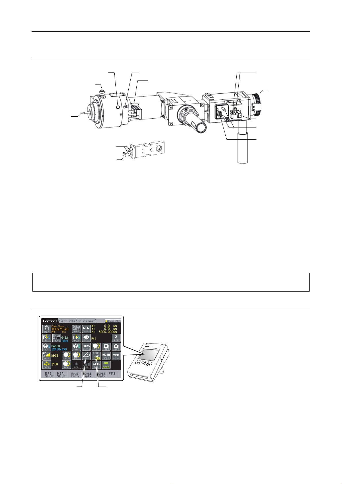
Chapter 1 System Configurations and Part Names
r
1.4 Name of Each Part
TI-TIRF-E motorized illuminator unit and remote control pad
(5) Condenser lens locking screw
(2) Laser position adjustment knob
(for forward and backward
adjustment)
(4) Focal point adjustment knob
(3) ND filter sliders
CAUT
L
A
A
V
VORSICH
S
KL
WEN
OID E
NICHT DEM
ER
I
A
O
S
R
N
S
N
–
AD
X
E
PO
A
3B,
C
T
B
IA
LAS
–
D
S
T
E
LASE
URE T
IO
S
C
S
TRAHL
N W
KUNG
3B
R
O T
HE
STR
N O
AUS
HE
G
AHLUNG
E
P
B
Ö
SET
E
E
FFNET
N
AM
Z
EN
M
G
NET
A
PEN
BE
O
N
THE
E
B
TO
WH
3
ERSTRAHLUN
RE
U
TION
CLASS
POS
–
N
RADIA
O
I
OID EX
UT
A
LASER
C
(10) ND filter sliders
AUSSETZEN
AHL
R
KUNG GEÖFF
T
S
LAS
–
DEC
M
3B,
HT
AB
DE
E
C
T
SI
ICH
N
WENN
KLASS
VOR
AV
(12) Connector for the
HG fiber light
source adapter
(1) Optical fibe
CAUTION
LASER R
–
AVO
CLASS 3B
A
DIA
ID EXPOSURE
TION WHEN OPE
V
O
RSIC
TO T
WE
H
N
T
NN
HE BEAM
I
N
CHT
–
LA
AB
D
S
DECK
EM ST
E
RS
UNG
T
R
RAHLU
AHL
G
A
EÖFFN
USSETZEN
NG
E
T
(11) Excitation filter slider
(8) Aperture diaphragm
centering screws
(9) Aperture diaphragm
(6) Field diaphragm centering screws
open/close lever
(7) Field diaphragm open/close lever
Figure 1.4-13
Parts used in the TIRF microscopy operation
(1) Optical fiber
(2) Laser position adjustment knob
(for forward and backward adjustment *)
(3) ND filter sliders
(4) Focal point adjustment knob
(5) Condenser lens locking screw
Parts used in the epi-fl microscopy operation
(6) Field diaphragm centering screws
(7) Field diaphragm open/close lever
(8) Aperture diaphragm centering screws
(9) Aperture diaphragm open/close lever
(10) ND filter sliders
(11) Excitation filter slider
(12) Connector for the HG fiber light source
adapter
The TI-RCP remote control pad (or TI-ERGC ergo controller) allows users to change illumination to TIRF
or episcopic as well as adjust the laser right or left (TIRF illumination angle adjustment).
TI-RCP remote control pad
TIRF Angle button
Figure 1.4-14
TIRF / EPI button
User can perform the following for the TI-TIRF-E
the remote control pad:
• TIRF/EPI button:
The illumination is changed to TIRF (laser light)
or episcopic.
• TIRF Angle button:
TIRF illumination position (illumination angle)
adjustment *
* The laser is adjusted right or left and the
illumination angle of TIRF illumination (total
reflection illumination) is adjusted.
1-46
Page 61
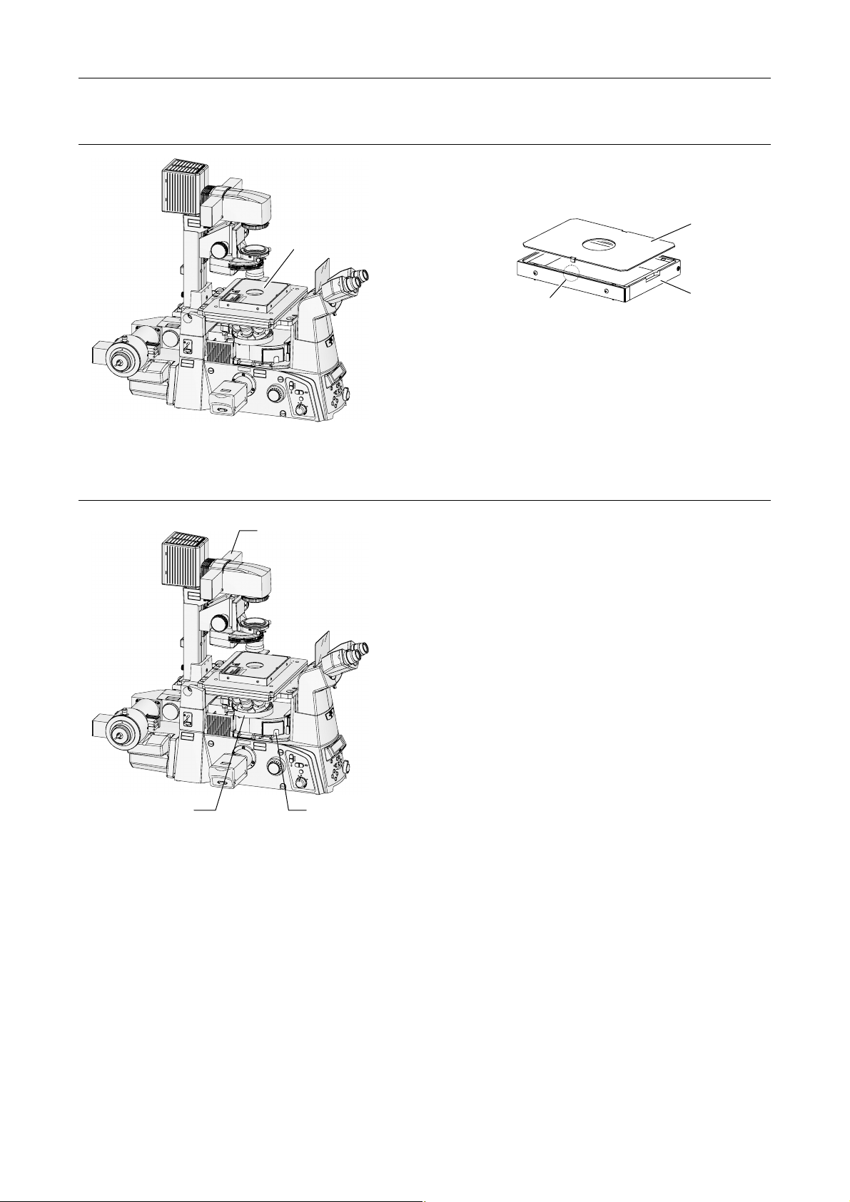
Laser safety cover
C
A
U
T
I
O
N
–
C
L
A
S
S
3
L
B
A
S
E
R
R
A
D
I
A
T
I
O
N
W
A
V
H
O
E
I
N
D
O
E
P
X
E
P
N
O
S
U
R
E
T
O
T
H
E
B
E
A
M
V
O
R
S
I
C
H
T
–
L
A
S
E
K
R
L
S
A
T
S
R
S
A
E
H
3
L
B
U
,
N
G
W
E
N
N
A
B
D
E
C
K
U
N
N
G
I
C
H
T
G
E
D
Ö
E
F
M
F
S
N
T
E
R
T
A
H
L
A
U
S
S
E
T
Z
E
N
Chapter 1 System Configurations and Part Names
1.4 Name of Each Part
The laser safety cover prevents laser light from
leaking. If the laser safety cover is not attached, the
motorized shutters of the laser unit do not open.
Laser safety cover
M
T
A
C
E
U
B
D
O
O
T
R
N
P
E
O
I
R
R
T
U
E
A
S
I
E
S
R
D
O
A
U
D
L
A
P
T
E
X
R
R
T
B
E
T
E
3
I
E
R
P
R
M
E
S
A
ID
U
E
S
S
S
E
O
S
A
A
V
I
V
O
I
L
L
T
A
P
T
C
C
H
X
E
G
E
J
I
B
L
D
O
I
R
O
E
M
S
V
O
A
A
R
L
F
Safety interlock (both sides)
Figure 1.4-16
Upper cover
Body
C
A
U
T
I
O
N
L
A
S
E
R
R
A
A
V
O
I
D
E
X
V
O
R
S
I
C
H
T
K
L
A
S
S
E
3
B
W
E
N
N
A
B
D
N
I
C
H
T
D
E
M
Laser safety kit
C
A
U
T
I
O
N
L
A
S
E
R
R
A
A
V
O
I
D
E
X
V
O
R
S
I
C
H
T
K
L
A
S
S
E
3
B
W
E
N
N
A
B
D
N
I
C
H
T
D
E
M
Protection plate
(for nosepiece)
–
C
L
A
S
S
3
B
D
I
A
T
I
O
N
W
H
E
N
O
P
P
E
O
N
S
U
R
E
T
O
T
H
E
B
E
A
M
–
L
A
S
E
R
S
T
R
A
H
L
U
,
N
G
E
C
K
U
N
G
G
E
Ö
F
F
S
N
T
E
R
T
A
H
L
A
U
S
S
E
T
Z
E
N
Figure 1.4-15
C
A
U
T
I
O
N
–
C
L
A
S
S
3
L
B
A
S
E
R
R
A
D
I
A
T
I
O
N
W
A
V
H
O
E
I
N
D
O
E
P
X
E
P
N
O
S
U
R
E
T
O
T
H
E
B
E
A
M
V
O
R
S
I
C
H
T
–
L
A
S
E
K
R
L
S
A
T
S
R
S
A
E
H
3
L
B
U
,
N
G
W
E
N
N
A
B
D
E
C
K
U
N
N
G
I
C
H
T
G
E
D
Ö
E
F
M
F
S
N
T
E
R
T
A
H
L
A
U
S
S
E
T
Z
E
N
A
E
B
O
T
R
N
P
E
O
I
R
R
T
U
E
A
S
I
S
D
O
A
L
A
P
X
R
B
E
R
3
E
S
ID
S
S
O
A
A
V
L
L
A
C
–
C
L
A
S
S
3
B
D
I
A
T
I
O
N
W
H
E
N
O
P
P
E
O
N
S
U
R
E
T
O
T
H
E
B
E
A
M
–
L
A
S
E
R
S
T
R
A
H
L
U
,
N
G
E
C
K
U
N
G
G
E
Ö
F
F
S
N
T
E
R
T
A
H
L
A
U
S
S
E
T
Z
E
N
Figure 1.4-17
A
V
O
I
D
E
X
P
O
S
L
U
A
R
S
E
E
R
L
I
G
H
T
I
S
F
E
R
M
O
I
M
T
T
E
T
D
H
I
S
C
A
U
A
T
P
I
O
E
N
R
–
T
C
U
L
R
A
S
E
S
3
L
B
A
S
E
R
R
A
D
I
A
T
I
O
N
W
A
H
V
O
E
N
I
D
O
E
P
X
E
P
N
O
S
U
R
E
T
O
T
H
E
B
E
A
M
V
O
R
S
I
C
H
T
–
L
A
S
E
K
R
L
S
A
T
S
R
S
A
E
H
L
3
U
B
N
,
G
W
E
N
N
A
B
D
E
C
K
U
N
N
G
I
C
H
G
T
E
D
Ö
E
F
M
F
N
S
E
T
R
T
A
H
L
A
U
S
S
E
T
Z
E
N
Filter slider cover
M
T
C
U
D
O
E
R
U
D
T
E
R
T
E
T
E
I
P
R
M
A
U
E
S
E
V
IS
O
I
T
P
T
C
H
X
E
E
J
IG
B
L
D
O
I
R
O
E
M
S
V
O
A
A
R
L
F
A
V
O
I
D
E
X
P
O
S
L
U
A
R
S
E
E
R
L
I
G
H
T
I
S
F
E
R
M
O
I
M
T
T
E
T
D
H
I
S
C
A
U
A
T
P
I
O
E
N
R
–
T
C
U
L
R
A
S
E
S
3
L
B
A
S
E
R
R
A
D
I
A
T
I
O
N
W
A
H
V
O
E
N
I
D
O
E
P
X
E
P
N
O
S
U
R
E
T
O
T
H
E
B
E
A
M
V
O
R
S
I
C
H
T
–
L
A
S
E
K
R
L
S
A
T
S
R
S
A
E
H
L
3
U
B
N
,
G
W
E
N
N
A
B
D
E
C
K
U
N
N
G
I
C
H
G
T
E
D
Ö
E
F
M
F
N
S
E
T
R
T
A
H
L
A
U
S
S
E
T
Z
E
N
RESET
-
Coarse
Fine
ExFine
ON/OFF
6V
30W
Coarse
Fine
ExFine
ON/OFF
6V30W
Z
DISPLAY
RECALL
BRIGHTNESS
Obj.
MEMORY
FOCUS
PFS
ON
EYE
R100
L100
12V100W
L80
MAX.
Obj.
12V100W
MAX.
RESET
Z
DISPLAY
RECALL
BRIGHTNESS
MEMORY
FOCUS
PFS
ON
EYE
R100
L100
L80
Filter cube port cover
retaining plate
* If the safety interlock part is touched or gotten wet,
misoperation may occur.
The laser safety kit is composed of the filter slider
cover, protection plate, filter cube port fixed plate, and
safety labels.
Before using the product, check that the part shown
in the left figure is attached.
* For the types and positions of safety labels, see
Section 1.3.2, “Ti-E Microscope Body.”
1-47
Page 62
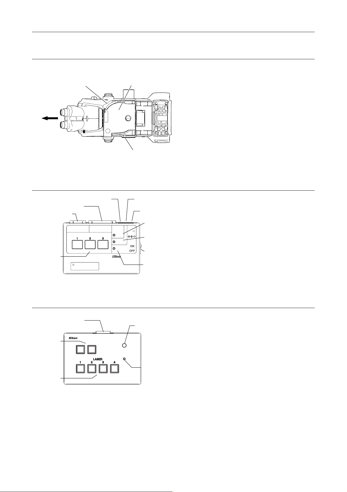
Chapter 1 System Configurations and Part Names
r
A
r
r
r
r
1.4 Name of Each Part
TI-FLC-E motorized epi-fl filter turret or TI-FLC-E/HQ motor epi-fl filter turret
Filter cube port
(and its cover)
Front
TI-LUSU shutter unit
Safety cover signal connecto
Laser unit connecto
Serial IF connecto
RS-232C LASER UNIT
Laser shutter
switch / indicato
Exclusive use for TI-TIRF system
Don't use this unit with other systems.
Shutter lever (O: open, C: close)
Figure 1.4-18
LASER SHUTTER
Figure 1.4-19
TI-FLC-E motorized epi-fl
filter turret or TI-FLC-E/HQ
motorized epi-fl filter turret
Eyepiece optical path
signal connector
C adapter
connector
Safety cover
INPUT
1A
close lamp
Eyepiece optical
path closed lamp
Power switch
SAFETY
COVER
CLOSE
BINO
CLOSE
POWER
12V
TI-LUSU
Power lamp
The epi-fl filter turret is used to select an excitation
method by rotating the turret to change filter cubes
including a dichroic mirror.
The shutter unit controls motorized shutters in the
laser unit.
Use this unit in combination with the C-LU2, C-LU3 or
C-LU3EX laser unit.
TI-LU4SU shutter unit LU4
Laser unit connecto
Option switch
Laser shutter
switch
TI-LU4SU
Figure 1.4-20
Indicator lamp
LASER
EMISSION
POWER
Power lamp
The shutter unit controls motorized shutters in the
laser unit.
Use this unit in combination with the LU4A laser unit.
If the safety interlock functions, all the shutters are
closed, and the lamp turns off.
To unlock the safety interlock, solve what caused the
safety interlock being locked, then cancel the safety
interlock from the software.
1-48
Page 63
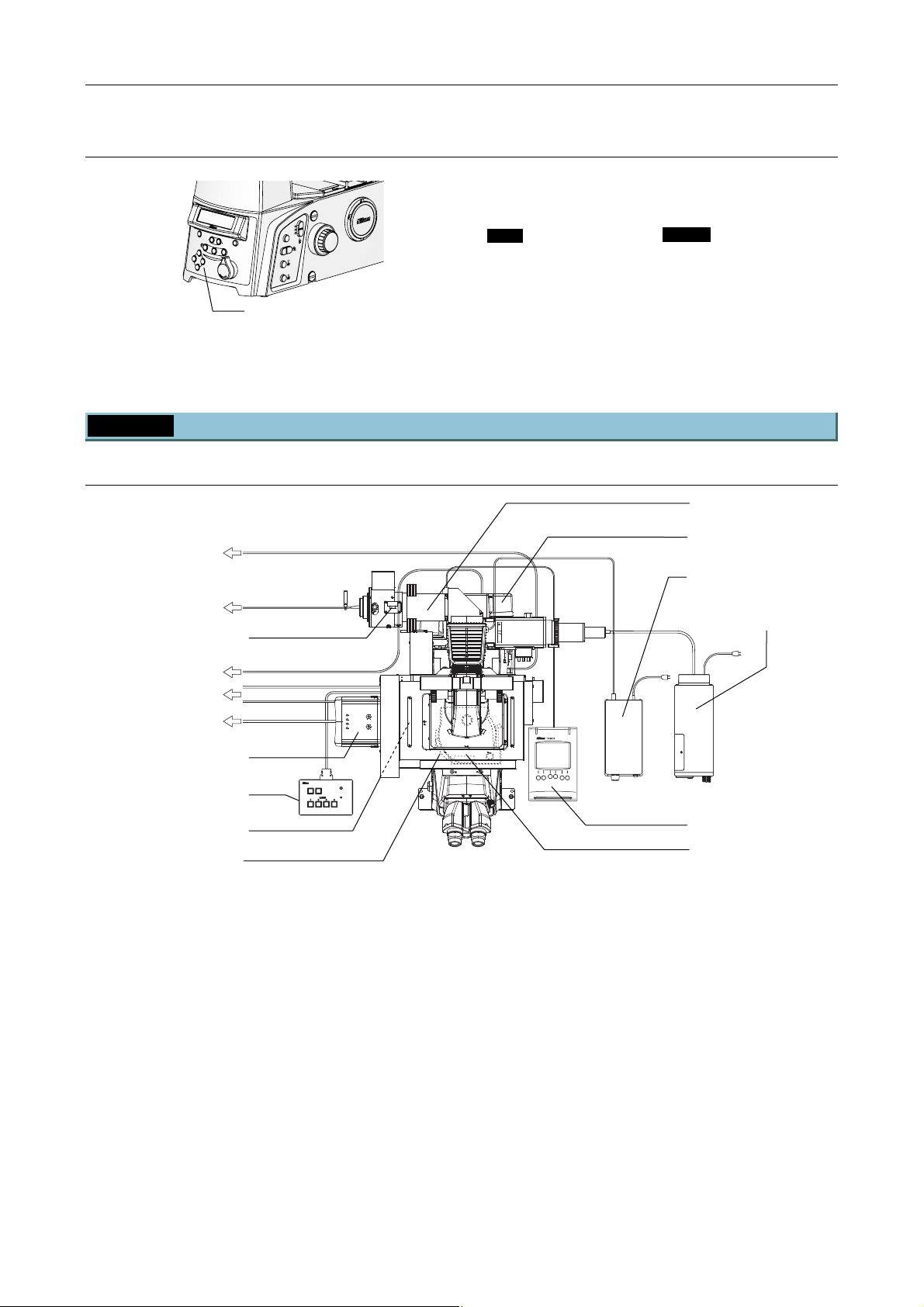
Chapter 1 System Configurations and Part Names
(
)
1.4 Name of Each Part
Optical path selector switch (on the microscope body)
The laser shutter does not open when the nosepiece
tube route of the optical path (“EYE”) is selected.
Coarse
Fine
BRIGHTNESS
FOCUS
DISPLAY
-
Z
RESET
EYE
ON
MEMORY
L100
PFS
R100
L80
1.5X
1X
Epi Shutter
ExFine
FL Block
Refocus
Escape
Optical path selector switch
Figure 1.4-21
Ti-E
EYE Observation port 100%
L100 Left port 100%
L80 Left port 80%
and observation port 20%
R100 Right port 100%
Ti-E/B
EYE Observation port 100%
L100 Left port 100%
L80 Left port 80%
and observation port 20%
B100 Bottom port 100%
1.4.3 Motorized TIRF Illuminator Unit, LU4A, N-STORM and Ti-E System
When used with four-laser module A
Motorized TIRF illuminator
unit
Hub controller A
with AC adapter
Power supply device for
the diascopic illumination
HG fiber light source
To laser unit
To laser unit
STORM slider
CLASS 3B
CLASS 3B
–
–
CAUTION
LASER RADIATION WHEN OPEN
AVOID EXPOSURE TO THE BEAM
LASER RADIATION WHEN OPEN
AVOID EXPOSURE TO THE BEAM
CAUTION
To PC
To laser unit
To PC
EM-CCD camera
TI-LU4SU shutter unit LU4
3D-STORM port
Filter cube cover retaining
plate
TI-LU4SU
LASER
EMISSION
POWER
Remote control pad
Figure 1.4-22
TI-FLC-E/HQ motor epi-fl
filter turret,
with protection plate
(part of laser safety kit)
1-49
Page 64
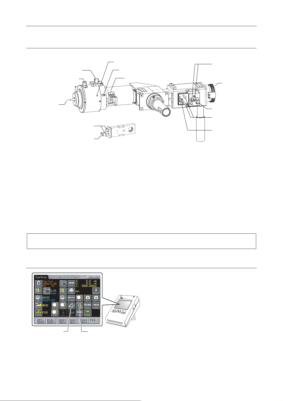
Chapter 1 System Configurations and Part Names
r
TI-TIRF-E motorized illuminator unit
(6) STORM slider
(2) Laser position adjustment knob
(for forward and backward
adjustment)
1.4 Name of Each Part
(5) Condenser lens locking screw
(4) Focal point adjustment knob
(3) ND filter sliders
CAUT
LA
AV
V
SER
KLASSE 3
W
O
O
NICHT DEM
I
ID
RSICH
E
O
NN
N
RADI
E
–
X
PO
ABDECKUNG
C
T
A
LASS
B
–
SUR
TI
,
LA
O
STR
N W
SE
E
3B
A
T
RSTR
HL
O
HEN OPEN
T
AUS
HE BEAM
G
AHLU
E
Ö
SETZEN
FFNET
NG
(11) ND filter sliders
N
G
NET
AM
N
TZE
E
OPEN
HE BE
GEÖFF
T
AUSS
O
T
NG
AHL
E
R
R
T
LASERSTRAHLU
TION WHEN
–
DECKU
M S
B,
CLASS 3B
T
–
ADIA
H
AB
DE
E 3
N
R
N
HT
ID EXPOSU
ASS
L
NIC
WEN
K
VORSIC
AVO
LASER
CAUTIO
(13) Connector for the
HG fiber light
source adapter
(1) Optical fibe
CAUTION
LASER RADIA
–
AVO
CLASS 3B
ID EXPOSURE
TION WHEN OPE
VO
RS
I
TO T
C
WE
HT
N
N
HE BEAM
ICHT DE
N
N
– L
A
A
BDE
SERST
M
C
K
S
UN
T
RAH
RAHL
G
L
G
AUSSET
UNG
EÖFF
NET
Z
E
N
(12) Excitation filter slider
(9) Aperture diaphragm
centering screws
(7) Field diaphragm centering screws
(10) Aperture diaphragm
open/close lever
(8) Field diaphragm open/close lever
Figure 1.4-23
Parts used in the TIRF microscopy operation
(1) Optical fiber
(2) Laser position adjustment knob
(for forward and backward adjustment)
(3) ND filter sliders
(For N-STORM, replace the ND16 by lambda
plate slider.)
(4) Focal point adjustment knob
(5) Condenser lens locking screw
(6) STORM slider
Parts used in the epi-fl microscopy operation
(7) Field diaphragm centering screws
(8) Field diaphragm open/close lever
(9) Aperture diaphragm centering screws
(10) Aperture diaphragm open/close lever
(11) ND filter sliders
(12) Excitation filter slider
(13) Connector for the HG fiber light source
adapter
The TI-RCP remote control pad (or TI-ERGC ergo controller) allows users to change the illumination to
TIRF or episcopic as well as adjust the laser right or left (TIRF illumination angle adjustment).
TI-RCP remote control pad
TIRF Angle button
TIRF / EPI button
Figure 1.4-24
User can perform the following for the TI-TIRF-E
the remote control pad:
• TIRF/EPI button:
The illumination is changed to TIRF (laser light)
or episcopic.
• TIRF Angle button:
TIRF illumination position (illumination angle)
adjustment *
* The laser is adjusted right or left and the
illumination angle of TIRF illumination (total
reflection illumination) is adjusted.
1-50
Page 65
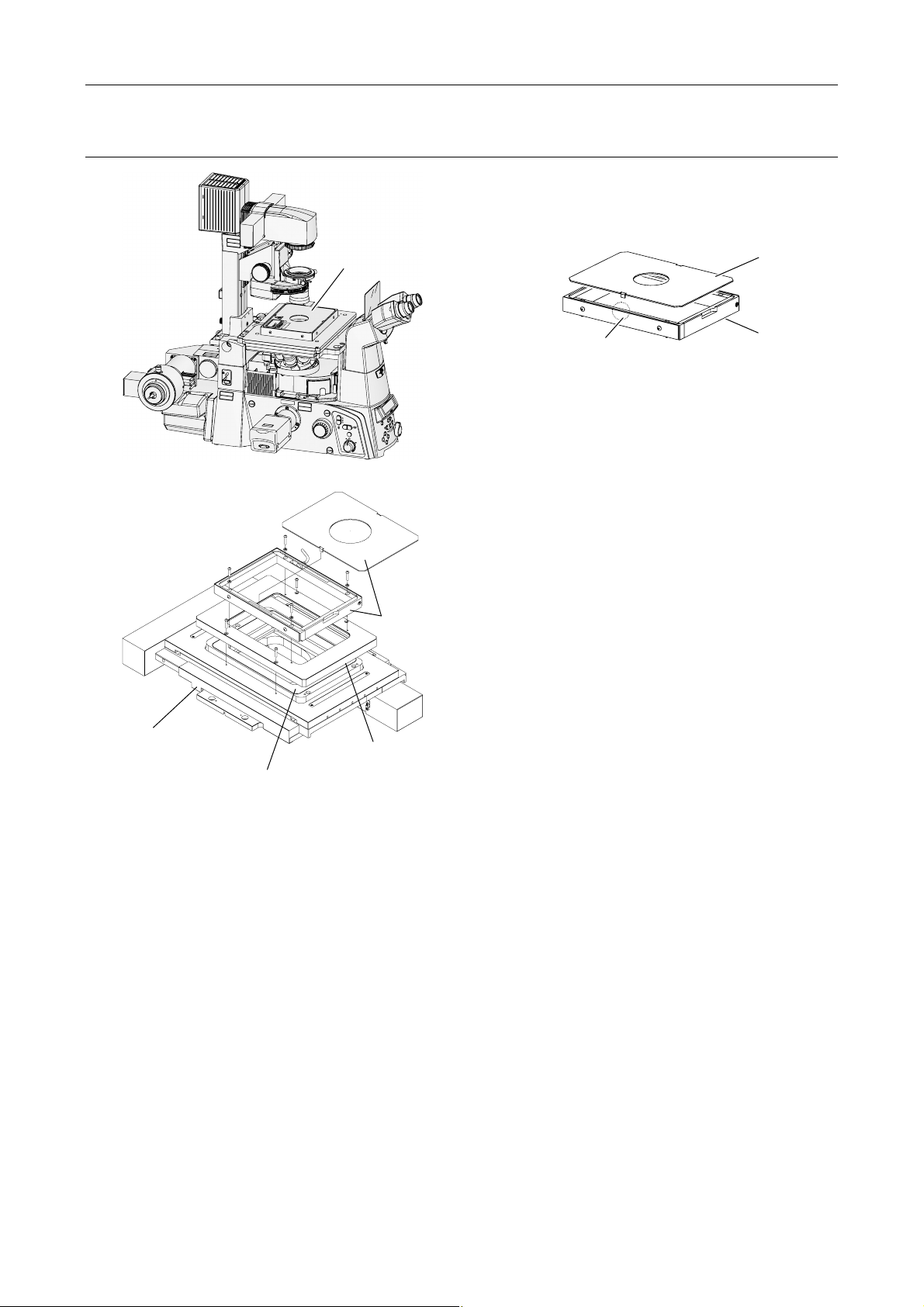
Laser safety cover
C
A
U
T
I
O
N
–
C
L
A
S
S
L
A
S
E
R
R
A
D
I
A
T
I
O
N
A
V
O
I
D
E
X
P
O
S
U
R
E
V
O
R
S
I
C
H
T
–
L
A
S
E
K
R
L
A
S
S
E
3
B
,
W
E
N
N
A
B
D
E
C
K
U
N
N
I
G
C
H
T
D
E
M
S
T
R
A
H
L
Chapter 1 System Configurations and Part Names
C
A
U
T
I
O
N
–
C
L
A
S
S
3
L
B
A
S
E
R
R
A
D
I
A
T
I
O
N
W
A
V
H
O
E
I
N
D
O
E
X
P
P
E
O
N
S
U
R
E
T
O
T
H
E
B
E
A
M
V
O
R
S
I
C
H
T
–
L
A
S
E
K
R
L
A
S
S
T
R
S
E
A
H
3
L
B
U
,
N
G
W
E
N
N
A
B
D
E
C
K
U
N
N
I
G
C
H
T
G
D
E
Ö
E
M
F
F
S
N
T
E
R
T
A
H
L
A
U
S
S
E
T
Z
E
N
M
T
A
C
E
U
B
D
O
O
T
R
N
E
P
IO
R
R
T
U
E
S
IA
E
S
R
D
O
A
U
D
A
P
L
T
X
R
TE
B
R
E
T
E
I
E
R
3
P
R
M
D
E
S
A
I
U
E
S
S
S
E
O
S
A
A
I
V
O
IV
L
L
T
A
P
T
C
C
H
X
E
E
J
IG
B
L
D
O
I
R
O
E
M
S
V
A
A
RO
L
F
3
B
W
H
E
N
O
P
E
N
T
O
T
H
E
B
E
A
M
S
T
R
A
H
L
U
N
G
G
E
Ö
F
F
N
E
T
A
U
S
S
E
T
Z
E
N
Figure 1.4-25
AVOID
EXPOSURE
L
A
S
E
R
L
I
G
H
T
I
S
F
E
R
M
O
IT
M
T
E
T
D
H
I
S
C
A
A
U
T
P
I
O
E
N
R
–
T
C
U
R
E
L
A
S
E
R
R
A
D
I
A
V
O
I
D
E
X
P
O
V
O
R
S
I
C
H
T
–
K
L
A
S
S
E
3
B
,
W
E
N
N
A
B
D
E
N
I
C
H
T
D
E
M
S
Laser safety cover
L
A
S
S
3
B
A
T
I
O
N
W
H
E
N
O
P
E
N
S
U
R
E
T
O
T
H
E
B
E
A
M
L
A
S
E
R
S
T
R
A
H
L
U
N
G
C
K
U
N
G
G
E
Ö
F
F
N
T
E
R
T
A
H
L
A
U
S
S
E
T
Z
E
N
Coarse
Fine
ExFine
Obj.
ON/OFF
6V30W
12V100W
MAX.
1.4 Name of Each Part
The cover prevents laser light from leaking. If the
laser safety cover is not attached, the motorized
shutters of the laser unit do not open.
Safety interlock (both sides)
RESET
Z
DISPLAY
RECALL
BRIGHTNESS
MEMORY
FOCUS
PFS
ON
EYE
R100
L100
L80
* If the safety interlock part is touched or gotten
wet, misoperation may occur.
When using piezo-stages:
Figure 1.4-26
Upper cover
Body
TI-S-ER Motorized
Stage with Encoders/
TI-S-E Motorized Stage
Piezo Z stage
Figure 1.4-27
Laser safety
cover
TI-TIRF-LSC Laser
Safety Cover/PZT
To use the piezo-stage together, the TI-TIRF-LSC Laser
safety cover/PZT is necessary. For how to attach the
TI-TIRF-LSC Laser safety cover/PZT, see “Setup
procedure and cautions” supplied with the TI-TIRF-LSC
Laser safety cover/PZT. Even when the TI-TIRF-LSC
Laser safety cover/PZT is attached, the motorized
shutters of the laser unit do not open unless the laser
safety cover is attached.
* If the safety interlock part is touched or gotten
wet, misoperation may occur.
1-51
Page 66
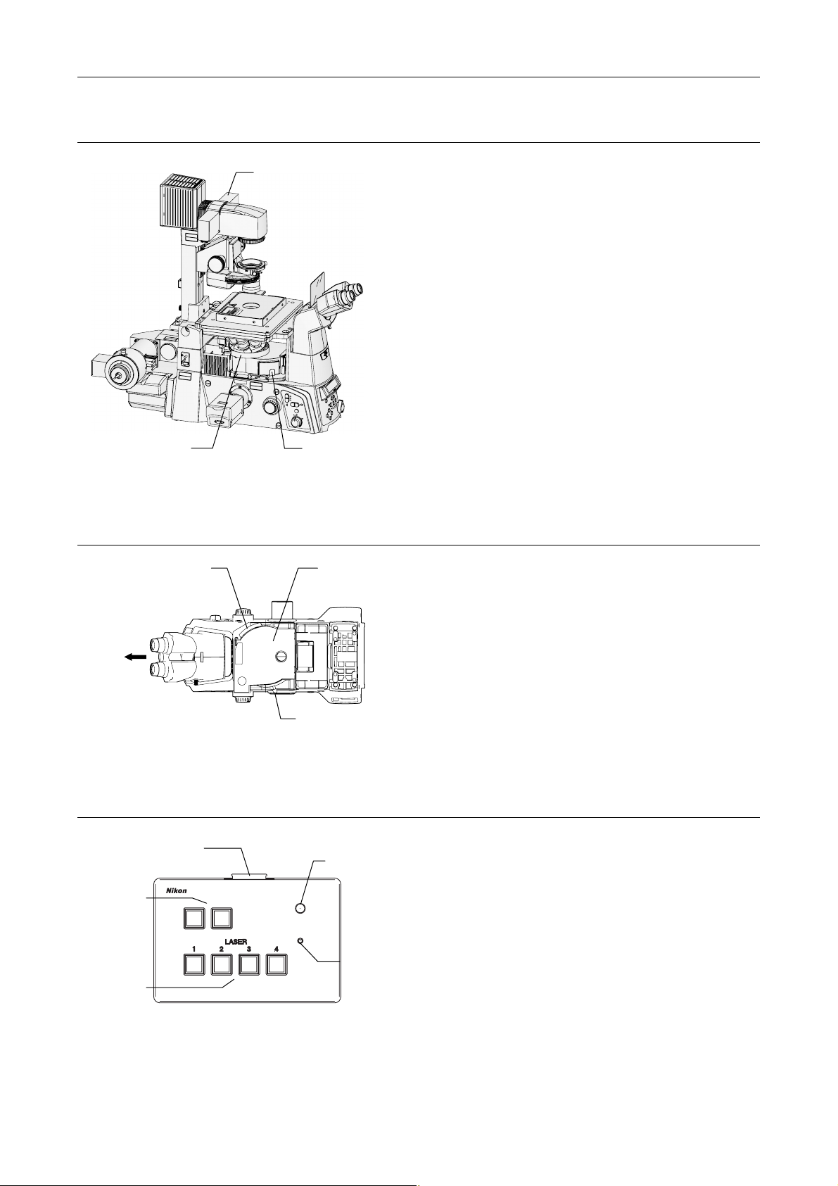
Laser safety kit
r
Chapter 1 System Configurations and Part Names
1.4 Name of Each Part
Filter slider cover
The laser safety kit is composed of the filter slider
cover, protection plate, filter cube port cover
retraining plate, and safety labels.
C
A
U
T
I
O
N
–
C
L
A
S
S
3
L
B
A
S
E
R
R
A
D
I
A
T
I
O
N
W
A
V
H
O
E
I
N
D
O
E
X
P
P
E
O
N
S
U
R
E
T
O
T
H
E
B
E
A
M
V
O
R
S
I
C
H
T
–
L
A
S
E
K
R
L
A
S
S
T
R
S
E
A
H
3
L
B
U
,
N
G
W
E
N
N
A
B
D
E
C
K
U
N
N
I
G
C
H
T
G
D
E
Ö
E
M
F
F
S
N
T
E
R
T
A
H
L
A
U
S
S
E
T
Z
E
N
Before using the product, check that the part
shown in the left figure is attached.
* For the types and positions of safety labels, see
Section 1.3.2, “Ti-E Microscope Body.”
Protection plate
(for nosepiece)
C
A
U
T
I
O
N
–
C
L
A
S
S
L
3
A
B
S
E
R
R
A
D
I
A
T
I
O
N
A
W
V
H
O
E
I
D
N
E
O
X
P
P
E
O
N
S
U
R
E
T
O
T
H
E
B
E
A
M
V
O
R
S
I
C
H
T
–
L
A
S
E
K
R
L
A
S
S
T
S
R
E
A
H
3
L
B
U
,
N
G
W
E
N
N
A
B
D
E
C
K
U
N
N
I
G
C
H
T
G
D
E
E
Ö
M
F
F
S
N
T
E
R
T
A
H
L
A
U
S
S
E
T
Z
E
N
Figure 1.4-28
M
T
A
C
E
U
B
D
O
O
T
R
N
E
P
IO
R
R
T
U
E
S
IA
E
S
R
D
O
A
U
D
A
P
L
T
E
X
R
B
R
E
E
ITT
E
R
3
P
R
M
D
E
S
A
I
U
E
S
S
S
E
O
S
A
A
I
V
O
L
L
TIV
A
P
T
C
C
H
X
E
E
J
IG
B
L
O
ID
R
O
E
M
S
V
O
A
A
R
L
F
AVOID
EXPOSURE
L
A
S
E
R
L
I
G
H
T
I
S
F
E
R
M
O
IT
M
T
E
T
D
H
I
S
C
A
A
U
T
P
I
O
E
N
R
–
T
C
U
L
R
A
S
E
S
3
L
B
A
S
E
R
R
A
D
I
A
T
I
O
N
W
A
V
H
O
E
I
N
D
O
E
P
X
E
P
N
O
S
U
R
E
T
O
T
H
E
B
E
A
M
V
O
R
S
I
C
H
T
–
L
A
S
E
K
R
L
S
A
T
S
R
S
A
E
H
3
L
U
B
N
,
G
W
E
N
N
A
B
D
E
C
K
U
N
N
G
I
C
H
G
T
E
D
Ö
E
F
M
F
S
N
T
E
R
T
A
H
L
A
U
S
S
E
T
Z
E
N
Coarse
Fine
ExFine
ON/OFF
6V30W
RESET
Z
DISPLAY
RECALL
BRIGHTNESS
Obj.
MEMORY
FOCUS
PFS
ON
EYE
R100
L100
12V100W
L80
MAX.
Filter cube port cover
retaining plate
TI-FLC-E motorized epi-fl filter turret or TI-FLC-E/HQ motor epi-fl filter turret
Filter cube port
(and its cover)
TI-FLC-E or
TI-FLC-E/HQ
The epi-fl filter turret is used to select an excitation
method by rotating the turret to change filter cubes
including a dichroic mirror.
Front
Figure 1.4-29
TI-LU4SU shutter unit LU4
Laser unit connecto
Option switch
Laser shutter
switch
TI-LU4SU
Figure 1.4-30
Shutter lever
(O: open, C: close)
Indicator lamp
LASER
EMISSION
POWER
Power lamp
The shutter unit controls motorized shutters in the
laser unit.
Use this unit in combination with the LU4A laser
unit.
If the safety interlock functions, all the shutters are
closed, and the lamp turns off.
To unlock the safety interlock, solve what caused
the safety interlock being locked, then cancel the
safety interlock from the software.
1-52
Page 67
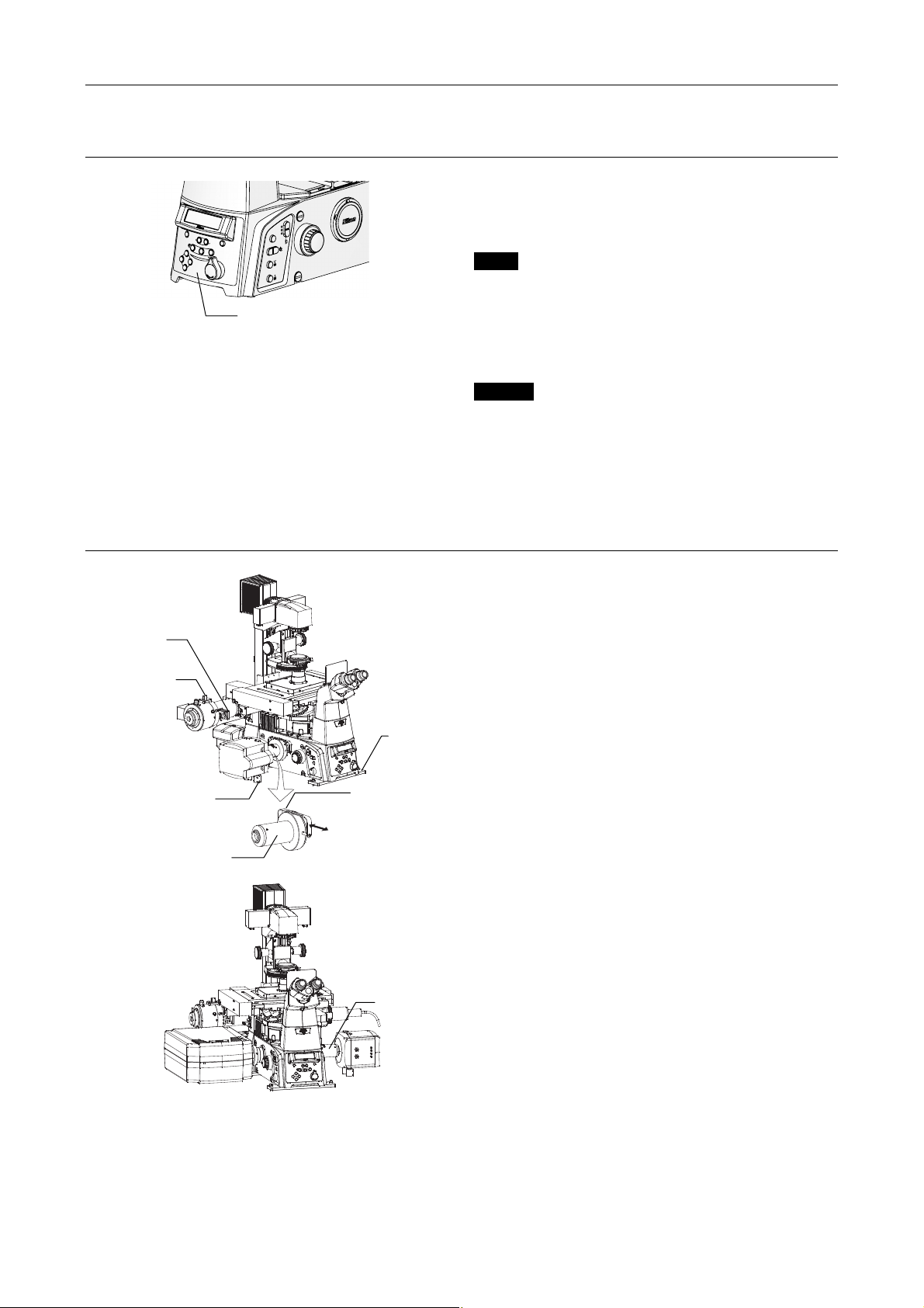
Chapter 1 System Configurations and Part Names
r
r
Optical path selector switch
Coarse
Fine
BRIGHTNESS
FOCUS
DISPLAY
Z
RESET
EYE
ON
MEMORY
L100
PFS
R100
L80
1.5X
1X
ExFine
Epi Shutter
FL Block
Refocus
Escape
Optical path selector switch
Figure 1.4-31
N-STORM
1.4 Name of Each Part
The laser shutter does not open when the
nosepiece tube route of the optical path (“EYE”) is
selected.
Ti-E
EYE Observation port 100%
L100 Left port 100%
L80 Left port 80% and observation port 20%
R100 Right port 100%
Ti-E/B
EYE Observation port 100%
L100 Left port 100%
L80 Left port 80% and observation port 20%
B100 Bottom port 100%
Lambda plate
slide
STORM slide
DSC support column
3D-STORM port
The 3D-STORM port connecting the Ti-E
microscope and EM-CCD camera when performing
the N-STORM microscopy is equipped with the
cylindrical lens that is placed in or out of the optical
imaging system to the camera by sliding the
handle. In normal microscopy and 2D-STORM
microscopy, remove the cylindrical lens out of the
optical path, and in capturing the 3D-STORM
Ti-E fixing
plate
image, insert it in the optical path.
If the cylindrical lens is installed during normal
microscopy and 2D-STORM microscopy, images
Cylindrical lens
IN/OUT handle
OUT
IN
are distorted. In 3D-STORM microscopy, the shape
of each bright spot changes to oval.
(When using this port together with the confocal
microscope A1, install the 3D-STORM port in the
right port. When using this port independently,
install it in the left port.)
3D-STORM port
Combination of A1 and 3D-STORM port
Figure 1.4-32
1-53
Page 68
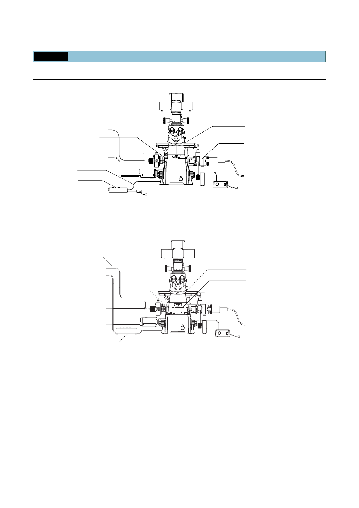
Chapter 1 System Configurations and Part Names
1.4 Name of Each Part
1.4.4 TI-PAU Photo Activation Illuminator Unit and Ti-U System
When used in combination with two-laser or three-laser unit
Specimen cover
TI-FLC epi-fl filter turret
Photo activation
illuminator unit
Interlock cable
TI-LUSU shutter
unit
CLASS 3B
–
LASER RADIATION WHEN OPEN
AVOID EXPOSURE TO THE BEAM
CAUTION
Figure 1.4-33
When used with four-laser module A
Interlock cable
Photo activation
illuminator unit
TI-LU4SU shutter
unit LU4
Specimen cover
TI-FLC epi-fl filter turret
CLASS 3B
–
CAUTION
LASER RADIATION WHEN OPEN
AVOID EXPOSURE TO THE BEAM
Figure 1.4-34
1-54
Page 69
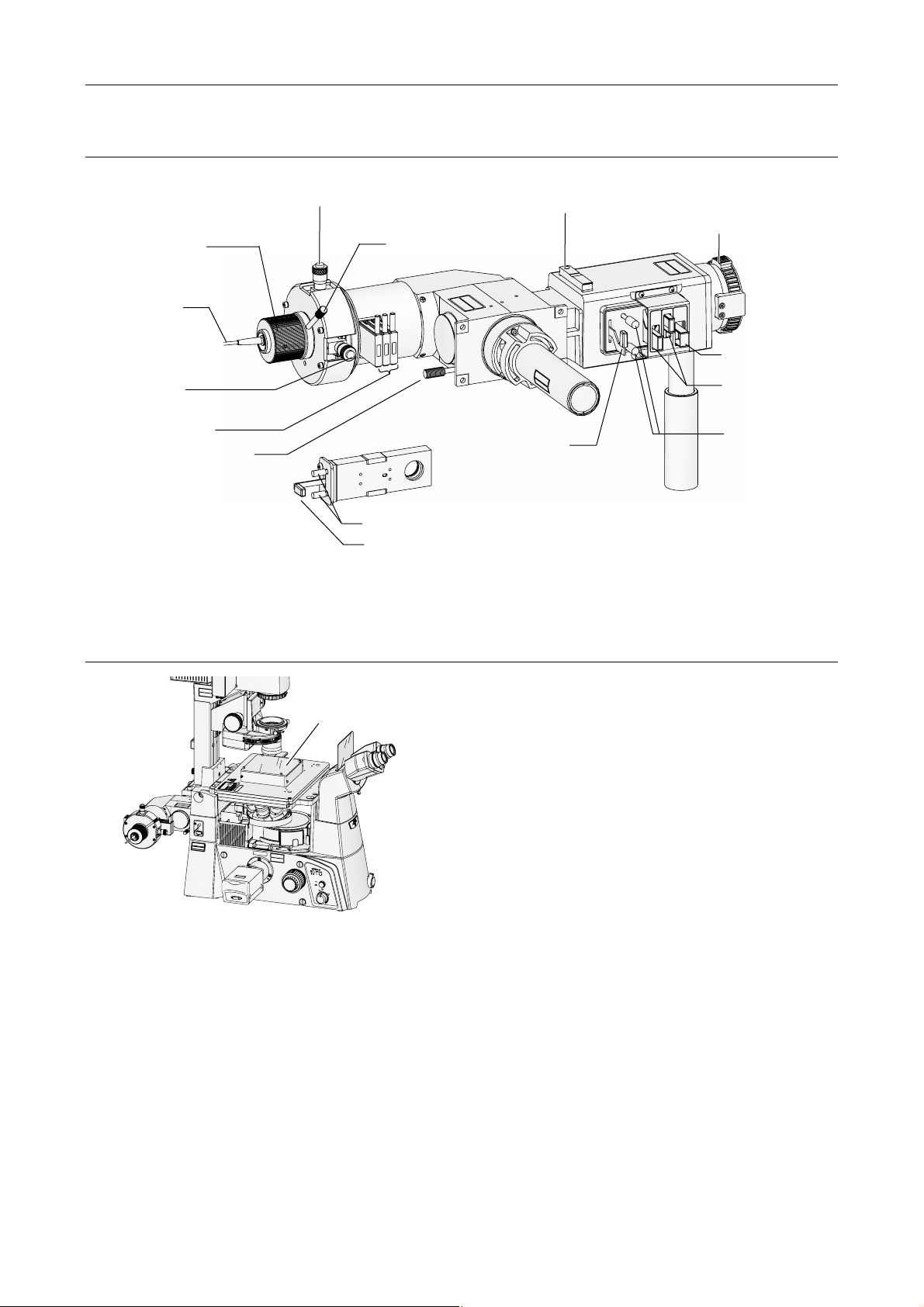
Chapter 1 System Configurations and Part Names
r
A
A
A
Photo Activation Illuminator Unit
1.4 Name of Each Part
Laser focus
adjustment knob
Optical fiber
Laser position
adjustment knob
(for right and left
adjustment)
ND filter sliders
Mirror switching lever
• Push in: Mirror IN
(epi illumination)
• Pull out: Mirror OUT
(laser light)
(* with the total reflection mirror)
Specimen cover
Laser position adjustment knob
(for forward and backward adjustment)
Laser focus adjustment
clamp screw
CAUTION
LASER RADIATION WHEN OPEN
AVOID EXPOSURE TO THE BEAM
VORSICHT
KLASSE 3B,
WENN ABDECKUNG GEFFNET
NICHT DEM STRAHL AUSSETZEN
LASERSTRAHLUNG
IN
IN
ND2
N
N
N
D
D
D
16
8
2
perture diaphragm
open/close lever
Field diaphragm centering screws
Field diaphragm open/close lever
Figure 1.4-35
HG fiber light source
uxiliary filter slider
adapter/lamphouse
mounting part for epi
illumination
TZEN
LASERSTRAHLUNG
CLASS 3B
NICHT DEM STRAHL AUSSE
WENN ABDECKUNG GEFFNET
KLASSE 3B,
VORSICHT
AVOID EXPOSURE TO THE BEAM
LASER RADIATION WHEN OPEN
CAUTION
CLASS 3B
S.
A.
CAUTION
LASER RADIATION WHEN OPEN
AVOID EXPOSURE TO THE BEAM
CLASS 3B
VORS
K
I
L
CHT LASERSTRAHLUNG
ASSE
WEN
N
I
N
CH
ABDECKUNG GE
3B
T
D
,
EM
S
TRAHL
A
USSETZ
FFNET
EN
FILTER
ND8
ND4
N
D
8
N
D
4
Excitation filter
slide
ND filter sliders
perture diaphragm
centering screws
CAUTION
–
C
LASS
3B
LAS
ER
RAD
IATIO
N W
A
VO
HEN OP
ID
EX
EN
POS
URE TO THE B
EAM
VORSI
CHT
–
LA
SERSTRAHLUNG
KLASS
E 3
B,
WENN ABDECKUNG G
NICHT DEM STRAHL AUSSET
EÖF
FNET
ZEN
The cover prevents illumination light from leaking.
Specimen cover
M
M
T
T
A
A
C
C
E
E
U
U
B
B
D
D
O
O
O
O
T
T
R
R
N
N
E
E
P
P
IO
IO
R
R
R
R
T
T
U
U
E
E
S
S
IA
IA
E
E
S
S
R
R
D
D
O
O
A
A
U
U
D
D
A
A
P
P
L
L
T
T
E
E
X
X
R
R
T
T
B
B
R
R
E
E
E
E
IT
IT
E
E
3
3
R
R
P
P
R
R
M
M
S
S
E
E
A
A
ID
ID
U
U
E
E
S
S
S
S
S
S
E
E
O
O
A
A
A
A
V
V
IS
IS
V
V
O
O
I
I
L
L
L
L
T
T
A
A
P
P
T
T
C
C
C
C
H
H
X
X
E
E
G
G
E
E
J
J
I
I
B
B
L
L
O
O
ID
ID
R
R
O
O
E
E
M
M
S
S
V
V
O
O
A
A
A
A
R
R
L
L
F
F
CAU
TION
CAUTIO
–
CLASS 3B
N
LAS
–
CLAS
ER
RAD
S 3
LAS
B
IAT
ER
IO
AVO
RADIAT
N WHEN O
ID
EXPOS
ION WH
PE
AVOID EX
URE
N
EN
TO TH
O
PEN
POSURE TO
E B
EAM
VO
THE
RSICHT
BE
AM
–
LASER
K
LAS
SE
STRAHL
VORSICH
3B,
WENN ABD
UNG
T
–
LASE
KLASSE
RSTRA
ECKUNG
NICHT DE
3B,
HLUNG
GEÖ
M STRAHL AUSSETZE
WEN
FFNET
N ABD
ECKUNG GEÖ
N
ICHT DEM STRAHL AUSSETZEN
N
FF
NET
AVOID
EX
POSUR
L
A
S
E
E
R
L
I
G
H
T
I
S
F
E
R
M
O
I
T
M
T
E
T
D
H
I
S
CAU
A
TI
P
O
E
N
R
–
T
C
U
L
R
AS
E
S 3B
L
AS
E
R
R
A
D
IAT
IO
N
W
A
H
V
O
E
N
ID
O
E
PE
X
PO
N
S
U
R
E TO
T
H
E
BE
A
M
V
O
R
S
IC
H
T
–
LA
S
ER
KL
S
A
TR
S
S
A
E 3
HL
U
B,
N
G
W
E
N
N
A
BD
EC
KU
N
N
G
IC
G
HT
D
E
Ö
E
FF
M
S
N
T
E
R
T
A
H
L A
U
S
SE
T
ZEN
ON
OFF
6V30W
12V100W
MAX.
Figure 1.4-36
1-55
Page 70
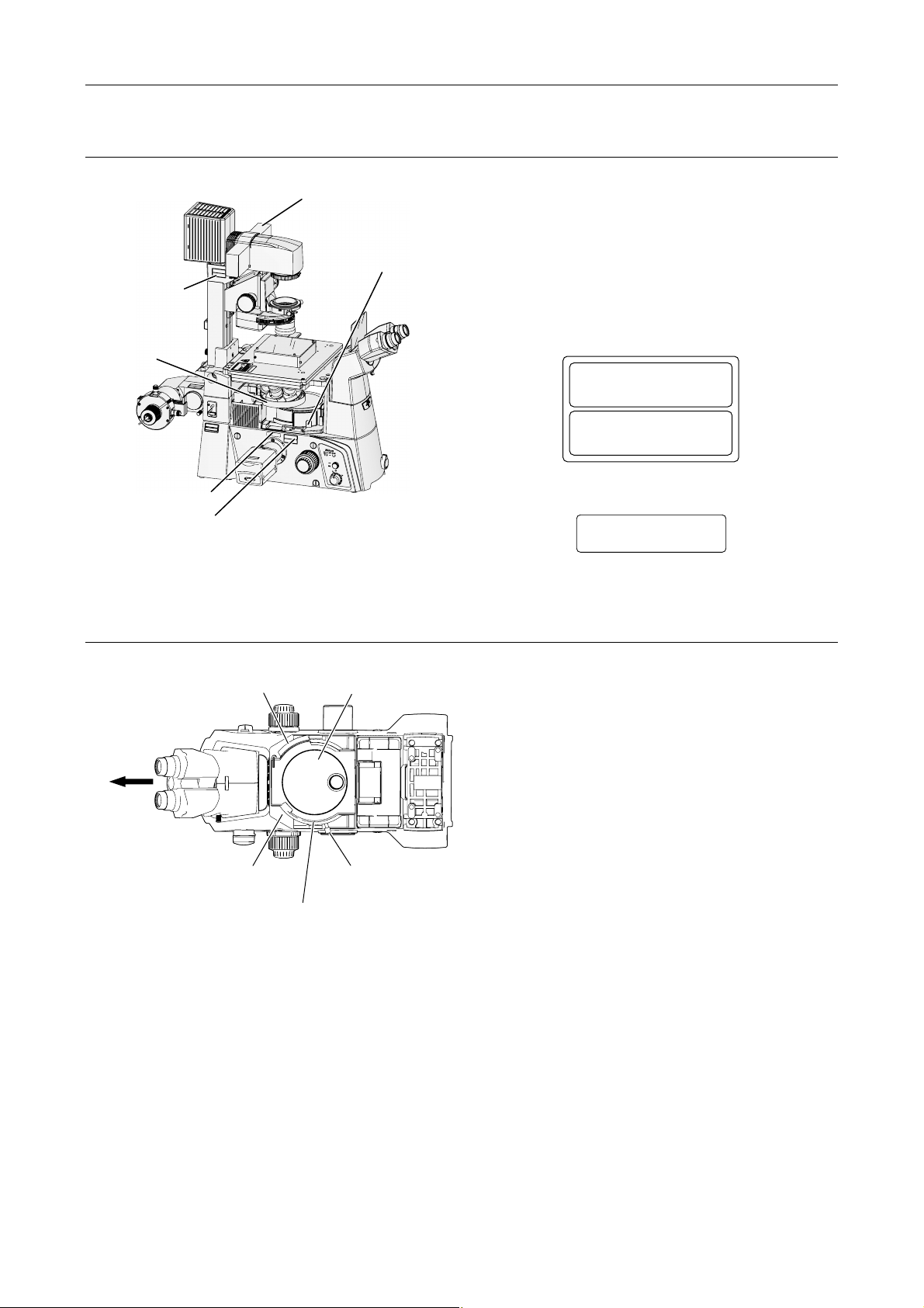
Laser safety kit
Chapter 1 System Configurations and Part Names
1.4 Name of Each Part
C
A
U
T
I
O
N
–
C
L
A
S
S
3
L
B
A
S
E
R
R
A
D
I
A
T
I
O
N
W
A
V
H
O
E
I
N
D
O
E
P
X
E
P
N
O
S
U
R
E
T
O
T
H
E
B
E
A
M
V
O
R
S
I
C
H
T
–
L
A
S
E
K
R
L
S
A
T
S
R
S
A
E
H
3
L
B
U
,
N
G
W
E
N
N
A
B
D
E
C
K
U
N
N
G
I
C
H
T
G
E
D
Ö
E
F
M
F
S
N
T
E
R
T
A
H
L
A
U
S
S
E
T
Z
E
N
Safety label (7)
Protection plate
(for nosepiece)
M
M
CT
CT
ODU
ODU
N
ION
T
TIO
URE TO BEA
URE TO BEA
IA
E
E
D
D
ADIA
POS
POS
LASER PR
LASER PR
TUR
TUR
R
R
TE
TE
E
E
E
E
3B
3B
MIT
MIT
ER RAD
S
S
AP
AP
ID EX
ID EX
E
E
SER R
S
SUR
SUR
E
E
IS
IS
VO
VO
LA
LA
TIV
TIV
A
A
T
T
CLAS
CLAS
H
H
EC
EC
EXPO
EXPO
LIG
LIG
OBJ
OBJ
R
R
E
E
S
S
OM
OM
AVOID
AVOID
R
R
LA
LA
F
F
C
A
U
T
I
O
C
N
A
U
–
T
I
C
O
L
N
A
L
–
S
A
S
C
S
L
3
E
A
B
R
S
S
R
A
L
3
D
B
A
I
S
A
E
T
R
I
A
O
V
R
N
O
A
W
D
I
D
IA
H
E
E
T
X
I
N
O
P
O
N
O
P
W
S
A
E
V
U
H
N
O
R
E
ID
E
N
E
T
O
O
X
P
P
T
E
O
H
N
E
S
U
B
R
E
E
A
T
M
V
O
O
T
R
H
S
E
I
C
B
H
E
T
A
M
–
L
K
A
L
S
A
E
S
R
S
S
V
E
O
T
R
R
3
A
B
S
H
I
,
C
L
H
W
U
T
N
E
–
G
N
N
L
A
A
S
B
E
K
D
R
L
A
S
E
S
T
C
N
R
S
K
I
E
A
U
C
H
N
H
3
L
G
T
B
U
,
D
N
E
G
G
M
E
Ö
S
W
T
F
E
R
F
N
N
A
N
E
H
T
L
A
B
A
D
U
E
S
C
S
K
E
U
T
N
N
Z
I
G
E
C
N
H
T
G
D
E
Ö
E
M
F
F
S
N
T
E
R
T
A
H
L
A
U
S
S
E
T
Z
E
N
Safety label (9)
(both sides)
Safety label (7)
(both sides)
Figure 1.4-37
TI-FLC epi-fl filter turret
Filter slider cover
A
V
O
ID
E
X
P
O
S
U
L
AS
R
E
E
R
L
IG
H
T
IS
F
E
R
M
O
IT
M
T
E
T
D
H
IS
C
A
A
U
T
PE
I
O
N
RT
–
C
U
L
R
A
S
E
S
3
L
B
A
S
E
R
R
A
D
I
A
T
I
O
N
W
A
H
V
O
E
N
I
D
O
E
P
X
E
P
N
O
S
U
R
E
T
O
T
H
E
B
E
A
M
V
O
R
S
I
C
H
T
–
L
A
S
E
K
R
L
S
A
T
S
R
S
A
E
H
L
3
U
B
N
,
G
W
E
N
N
A
B
D
E
C
K
U
N
N
G
I
C
H
G
T
E
D
Ö
E
F
M
F
N
S
E
T
R
T
A
H
L
A
U
S
S
E
T
Z
E
N
Filter cube port
cover retaining plate
ON
OFF
6V30W
12V100W
MAX.
The laser safety kit is composed of the filter slider
cover, protection plate for nosepiece, filter cube port
cover retaining plate, and safety labels, “(9) IEC
aperture label 2” and “(7) IEC caution label – Class
3B areas”. Before using the microscope, CHECK that
each part of the laser safety kit is correctly attached.
(See the figure left.)
(7) IEC caution label - Class 3B areas
CAUTION – CLASS 3B
LASER RADIATION WHEN OPEN
AVOID EXPOSURE TO THE BEAM
–
VORSICHT
KLASSE 3B,
WENN ABDECKUNG GEÖFFNET
NICHT DEM STRAHL AUSSETZEN
(9) IEC aperture label 2
AVOID EXPOSURE
LASER LIGHT IS EMITTED
FROM
LASERSTRAHLUNG
THIS APERTURE
Front
Filter cube port
(and its cover)
Filter cube address and
name on the optical path
Filter cube rotation control
Figure 1.4-38
TI-FLC epi-fl filter
turret
Shutter lever
(O: open, C: close)
The epi-fl filter turret is used to select an excitation
method by rotating the turret to change filter cubes
including a dichroic mirror.
1-56
Page 71
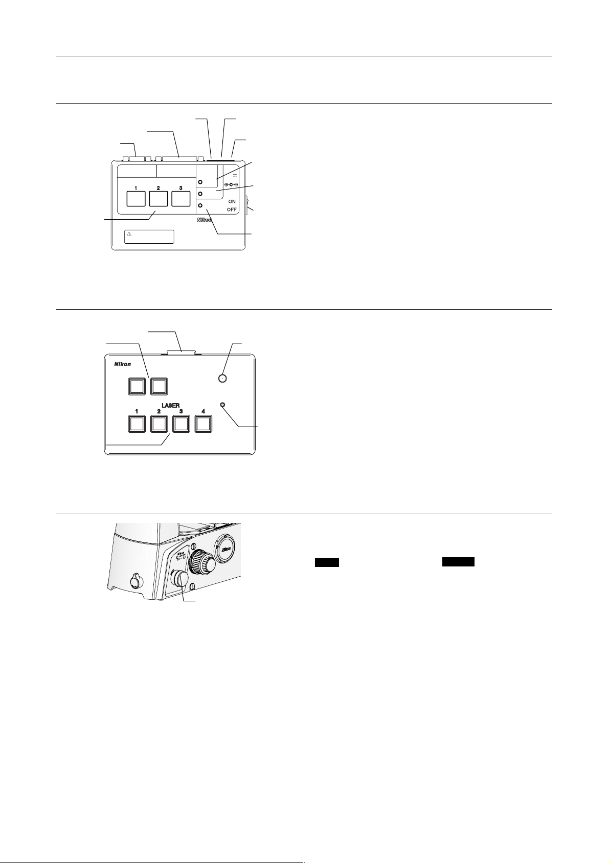
TI-LUSU shutter unit
A
r
r
r
r
Chapter 1 System Configurations and Part Names
1.4 Name of Each Part
Safety cover signal connector
Laser unit connecto
Serial IF connecto
RS-232C LASER UNIT
LASER SHUTTER
Laser shutter
switch / indicato
Exclusive use for TI-TIRF system
Don't use this unit with other systems.
Figure 1.4-39
TI-LU4SU shutter unit LU4
Laser unit connecto
Option switch
TI-LU4SU
Laser shutter
switch
Figure 1.4-40
Eyepiece optical path
TI-LUSU
INPUT
12V
1A
signal connector
C adapter
connector
Safety cover
close lamp
Eyepiece optical
path closed lamp
Power switch
SAFETY
COVER
CLOSE
BINO
CLOSE
POWER
The shutter unit controls motorized shutters in the
laser unit.
Use this unit in combination with the C-LU2, C-LU3 or
C-LU3EX laser unit.
Power lamp
Indicator lamp
The shutter unit controls motorized shutters in the
laser unit.
Use this unit in combination with the LU4A laser
LASER
EMISSION
POWER
unit.
If the safety interlock functions, all the shutters are
closed, and the lamp turns off.
To unlock the safety interlock, solve what caused
Power lamp
the safety interlock being locked, then cancel the
safety interlock from the software.
Optical path selector knob (on the microscope body)
The laser shutter does not open when the binocular
route of the optical path (“EYE”) is selected.
PORT
PORT dial
(optical path selector knob)
Ti-U *
EYE Visual observation 100%
R Right port 100%
AUX Auxiliary port
L Left port 100%
Figure 1.4-41
* The Ti-U is also available with an optical-path
splitter prism preinstalled at the auxiliary port. The
light intensity ratio of visual observation to left port
is 20 to 80.
In this case, set the optical path selector knob as
follows:
EYE Observation port 100%
R Right port 100%
L80 Visual observation/left port = 20:80
L Left port 100%
(Visual observation/left port
= 20:80)
(Visual observation/right port
= 20:80)
Ti-U/B
EYE Visual observation 100%
R Right port 100%
B Bottom port 100%
L Left port 100%
1-57
Page 72
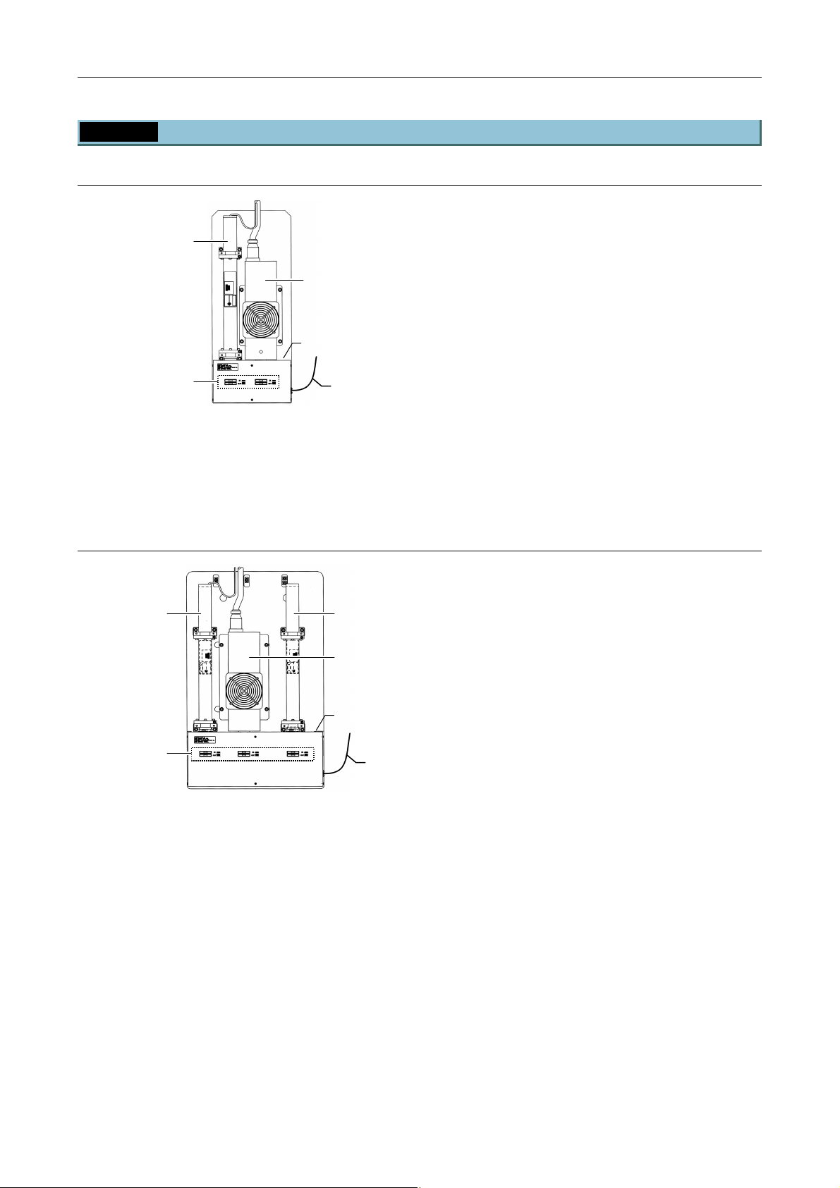
Chapter 1 System Configurations and Part Names
(5)
(6)
1.4 Name of Each Part
1.4.5 Laser Unit
Two-laser Unit (C-LU2)
(1) Laser mounting position L1
(2)
(1)
(3)
(4)
Figure 1.4-42
* For details of available lasers for each position of laser units, see Section 8.1.4, “Mountable Lasers” in
Chapter 8, “Specifications and Performance.”
(2) Laser mounting position L2
(3) Shutter unit connector
(4) ND filter slider
(5) Single-mode fiber
Three-laser unit (C-LU3)
(1) Laser mounting position L1
(2) Laser mounting position L2
(3) (1)
(3) Laser mounting position L3
(4) Shutter unit connector
(2)
(5) ND filter slider
(6) Single-mode fiber
(4)
(5)
Figure 1.4-43
* For details of available lasers for each position of laser units, see Section 8.1.4, “Mountable Lasers” in
Chapter 8, “Specifications and Performance.”
1-58
Page 73
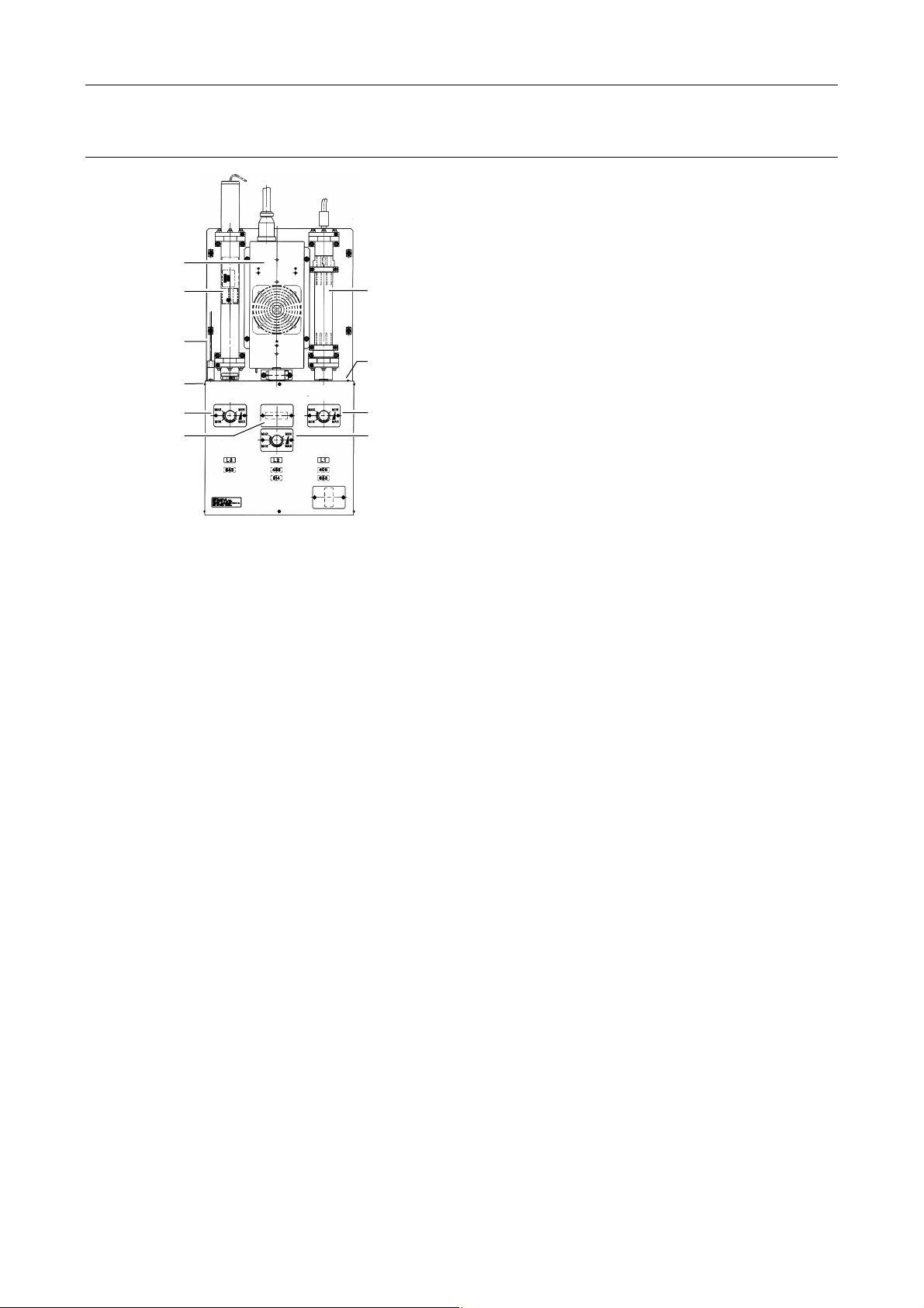
Chapter 1 System Configurations and Part Names
Three-laser unit EX (C-LU3EX)
(2)
(3)
(5)
(4)
1.4 Name of Each Part
(1) Laser mounting position L1
(2) Laser mounting position L2
(3) Laser mounting position L3
(4) Shutter unit connector
(1)
(5) Single-mode fiber
(6) Brightness control knob
(7) Ar wavelength selector (optional)
(8)
(8) AOM connector (optional)
(6)
(7)
Figure 1.4-44
(6)
(6)
* For details of available lasers for each position of laser units, see Section 8.1.4, “Mountable Lasers” in
Chapter 8, “Specifications and Performance.”
1-59
Page 74
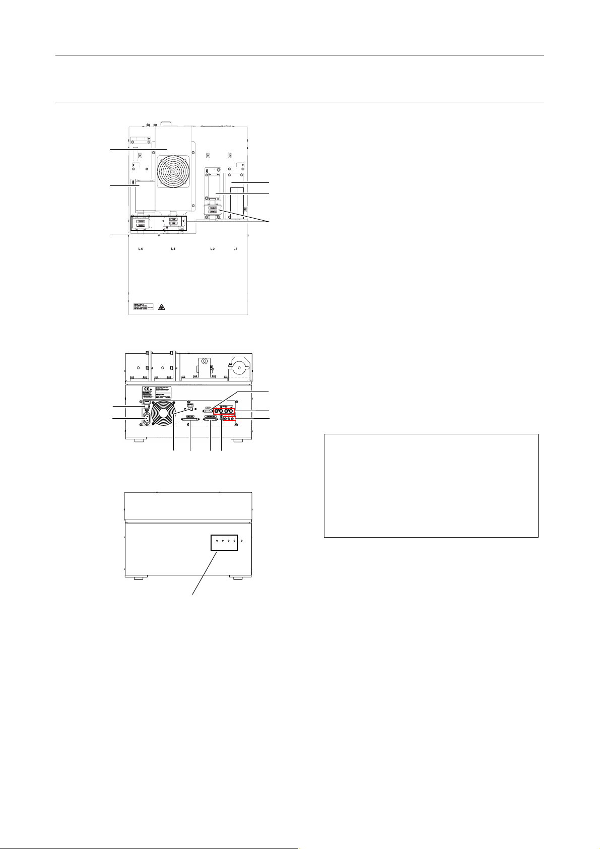
Chapter 1 System Configurations and Part Names
*
Four-laser module A (LU4A)
transportation.
Fix the laser unit with
(3)
(4)
(5)
(7)
(8)
four blocks during
Figure 1.4-45
(9) (14)
(11)
Figure 1.4-46
(10)
1.4 Name of Each Part
(1)
(2)
1
(6)
(13)
(15)
(12)
POWER
L3
L2
L4
L1
(1) Laser mounting position L1
(2) Laser mounting position L2
(3) Laser mounting position L3
(4) Laser mounting position L4
(5) Single-mode fiber
*1
(6)
ND filter sliders
(7) Power switch
(8) AC inlet
(9) Remote switch
(10) CONTROLLER connector
(Do not use in this system.)
(11) AOTF/PC connector
(Do not use in this system.)
(12) Interlock cable connectors
(13) LUSU connector
(14) USB connector
(15) LD connector
(Do not use in this system.)
*1: Installed only when the N-STORM kit is
mounted
Precautions when handling the laser unit
• The laser head and the optical fiber are
precisely aligned in these units.
Avoid subjecting the laser head or optical
fiber to vibration or shock. Contact the
distributor if you need to remove the laser
head from the unit due to laser malfunction
or other reasons.
Indicating shutter conditions
Figure 1.4-47
* For details of available lasers for each position of laser units, see Section 8.1.4, “Mountable Lasers” in
Chapter 8, “Specifications and Performance.”
1-60
Page 75
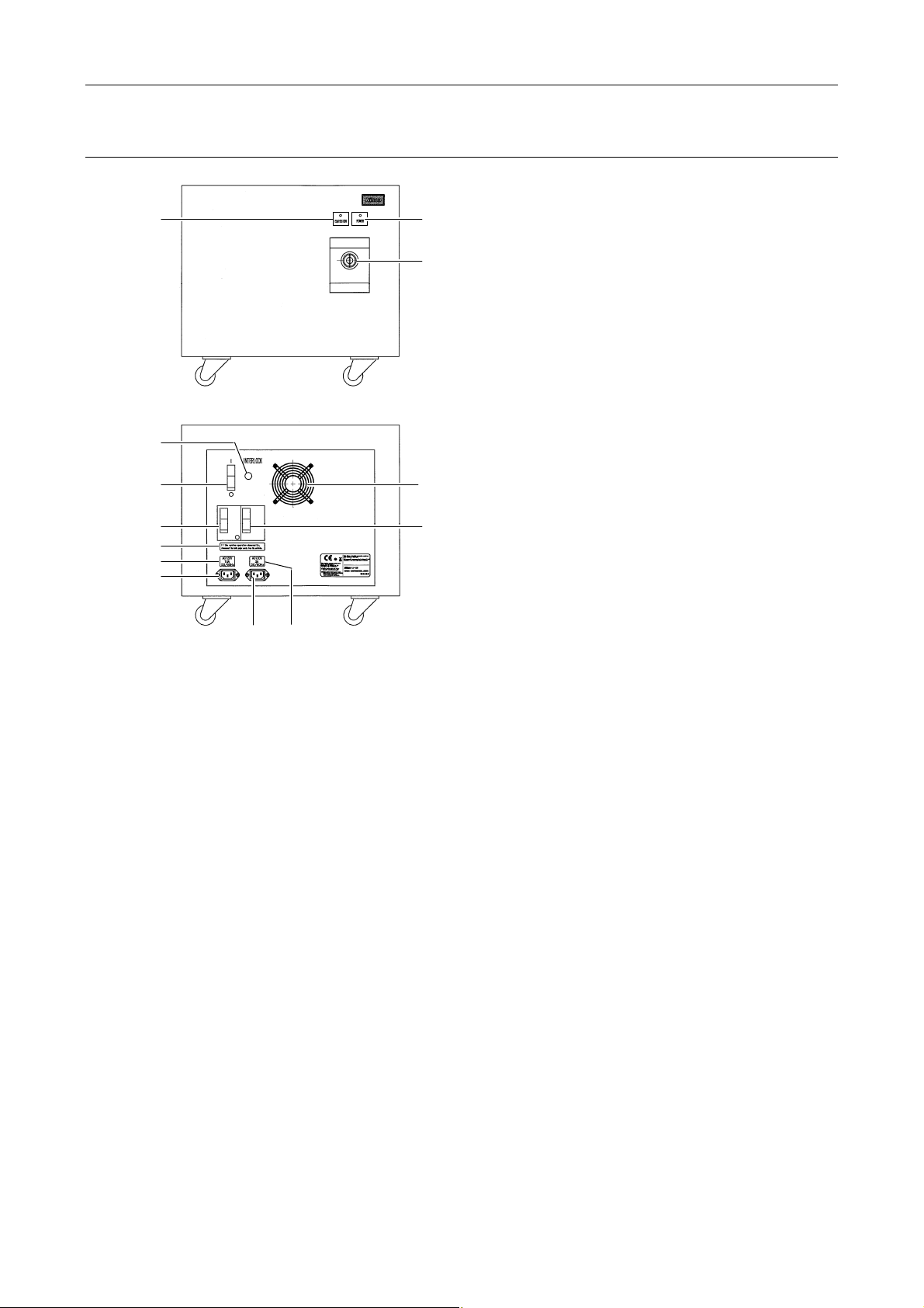
Chapter 1 System Configurations and Part Names
Four-laser PS rack (LU-LR)
(1)
(Front view)
(5)
(4)
1.4 Name of Each Part
(1) EMISSION laser indicator
(2)
(2) POWER laser indicator
(3) EMISSION key switch
(3)
(4) Power switch
(5) INTERLOCK connector
(6) Cooling fan
(7) Power breaker for 15 A line
(8) Power breaker for 5 A line
(9) Caution label
(10) Name plate for 15 A line ratings
(11) Name plate for 5 A line ratings
(12) AC inlet for 15 A line
(6)
(13) AC inlet for 5 A line
(7)
(9)
(10)
(12)
(11)
(13)
(Rear view)
Figure 1.4-48
(8)
1-61
Page 76
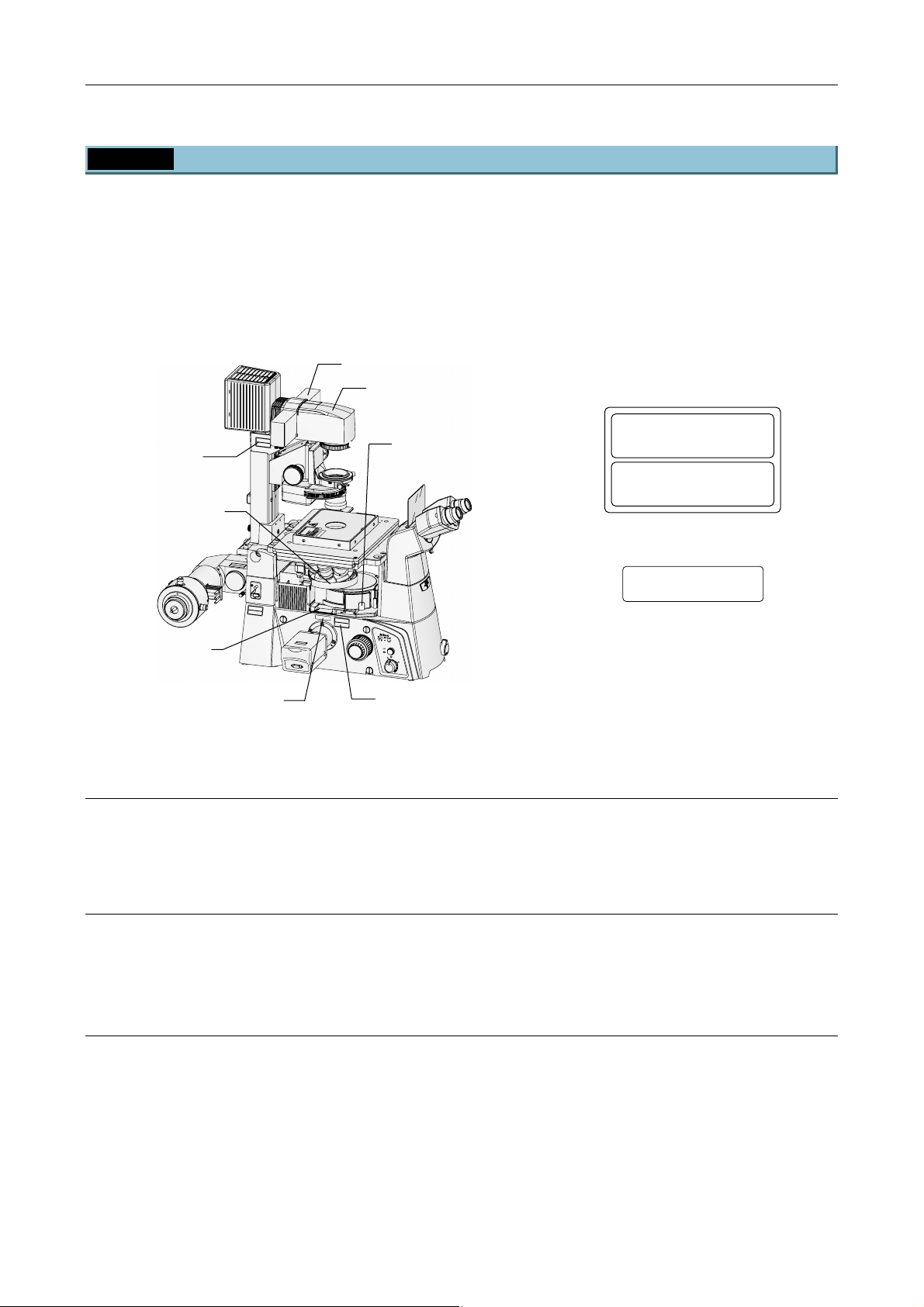
Chapter 1 System Configurations and Part Names
1.4 Name of Each Part
1.4.6 Laser Safety Kit
The laser safety kit is supplied with all laser products mounted onto a Ti microscope.
Labels affixed to each laser product include a name label and other types of necessary labels, both of which
are not shown here.
The laser safety kit is composed of the filter slider cover, protection plate for nosepiece, filter cube port cover
retaining plate, and safety labels, “(7) IEC caution label – Class 3B areas” and “(9) IEC aperture label”.
Before using the microscope, CHECK that each part of the laser safety kit is correctly attached. (See the
figure below.)
Safety label (7)
Protection plate
(for nosepiece)
Analyzer port
Safety label (9)
(Both sides)
Filter slider cover
C
A
U
T
IO
N
–
C
L
A
S
S
3
LA
B
S
E
R
R
A
D
I
A
T
I
O
N
W
A
V
H
O
E
ID
N
O
E
P
X
E
P
N
O
S
U
R
E
T
O
T
H
E
B
E
A
M
V
O
R
S
I
C
H
T
–
L
A
S
E
K
R
L
S
A
T
S
R
S
A
E
H
3
L
B
U
,
N
G
W
E
N
N
A
B
D
E
C
K
U
N
N
G
I
C
H
G
T
E
D
Ö
E
M
F
F
S
N
T
E
R
T
A
H
L
A
U
S
S
E
T
Z
E
N
A
R
R
E
S
O
A
V
L
A
C
A
U
T
IO
N
–
C
L
A
S
S
L
3
A
B
S
E
R
R
A
D
I
A
T
IO
N
W
A
V
H
O
E
I
D
N
E
O
X
P
P
E
O
N
S
U
R
E
T
O
T
H
E
B
E
A
M
V
O
R
S
I
C
H
T
–
L
A
S
E
K
R
L
A
S
S
T
S
R
E
A
H
3
L
B
U
,
N
G
W
E
N
N
A
B
D
E
C
K
U
N
N
I
G
C
H
T
G
D
E
E
Ö
M
F
F
S
N
T
E
R
T
A
H
L
A
U
S
S
E
T
Z
E
N
Figure 1.4-49
Filter slider cover
M
T
A
C
E
U
B
D
O
O
T
R
N
P
E
O
I
R
R
T
U
E
A
S
I
E
S
R
D
O
A
U
D
L
P
T
E
X
R
T
B
E
T
E
E
3
I
P
R
M
D
S
A
I
U
E
S
S
E
S
A
V
I
O
I
L
T
P
T
C
C
H
X
E
G
E
J
I
B
L
D
O
I
R
O
E
M
S
V
O
A
A
R
L
F
A
V
O
I
D
E
X
P
O
S
U
L
A
R
S
E
E
R
L
IG
H
T
IS
F
E
R
M
O
IT
M
T
E
T
D
H
IS
C
A
A
U
TI
P
O
E
N
R
–
T
C
U
L
R
A
S
E
S
3
L
B
A
S
E
R
R
A
D
IA
T
IO
N
W
A
V
H
O
E
N
ID
O
EX
PE
P
N
O
S
U
R
E
T
O
T
H
E
B
E
A
M
V
O
R
S
IC
H
T
–
L
A
S
E
K
R
L
S
A
T
S
R
S
A
E
H
3
L
U
B
N
,
G
W
E
N
N
A
B
D
E
C
K
U
N
N
G
IC
H
G
T
D
E
Ö
E
F
M
F
S
N
T
E
R
T
A
H
L
AU
S
S
ET
Z
E
N
Dia pillar illuminator
Filter cube port
cover retaining plate
ON
OFF
6V30W
12V100W
MAX.
Safety label (7)
(Both sides)
(7) IEC caution label -Class 3B areas
CAUTION – CLASS 3B
LASER RADIATION WHEN OPEN
AVOID EXPOSURE TO THE BEAM
–
VORSICHT
KLASSE 3B,
WENN ABDECKUNG GEÖFFNET
NICHT DEM STRAHL AUSSETZEN
LASERSTRAHLUNG
(9) IEC aperture label 2
AVOID EXPOSURE
LASER LIGHT IS EMITTED
THIS APERTURE
FROM
Figure 1.4-50
The filter slider cover is a component designed for preventing unintended exposure of eyes or skin at the
slider port to laser light emitted to the dia-pillar illuminator. To attach it to the Ti microscope, lay it over the
dia-pillar illuminator and secure it with the screws and nuts provided with the kit.
Filter cube port cover retaining plate
The filter cube port cover retaining plate is a component designed for preventing accidental leakage of laser
light upon occurrence of unintended opening of the filter cube port cover.
Attach it to the side of the epi-fl filter turret’s lower plate using the screws provided with the kit.
Safety labels
The label (7) affixed to the upper left side (when viewed from the Binocular eyepiece tube) of the dia pillar
indicates that the laser light may come out from the aperture when the lamphouse is removed for
replacement of the lamp inside.
Another labels (7) on both sides of the microscope base indicates that the laser light may come out from the
aperture while attaching the epi-fl filter turret or the nosepiece to the microscope.
The labels (9) on both sides of the microscope base indicates that the laser light may come out of the
analyzer port.
1-62
Page 77

Chapter 1 System Configurations and Part Names
1.4 Name of Each Part
Protection plate (for nosepiece)
The protection plate (for nosepiece) is a component designed for shielding the gap between the nosepiece
and the epi-fl filter turret to avoid accidental jamming of fingers inserted into the gap or the laser radiation
from the gap.
Two types of protection plate are prepared for the nosepiece being used. One for the TI-N6, TI-ND6 and
TI-ND6-E nosepieces is supplied with Ti-E and Ti-E/B, and the other for the TI-ND6-PFS nosepiece is
supplied with the nosepiece. Follow the procedure described in “4.2.3 Attaching the Laser Safety Kit” to
attach the protection plate in place.
1-63
Page 78
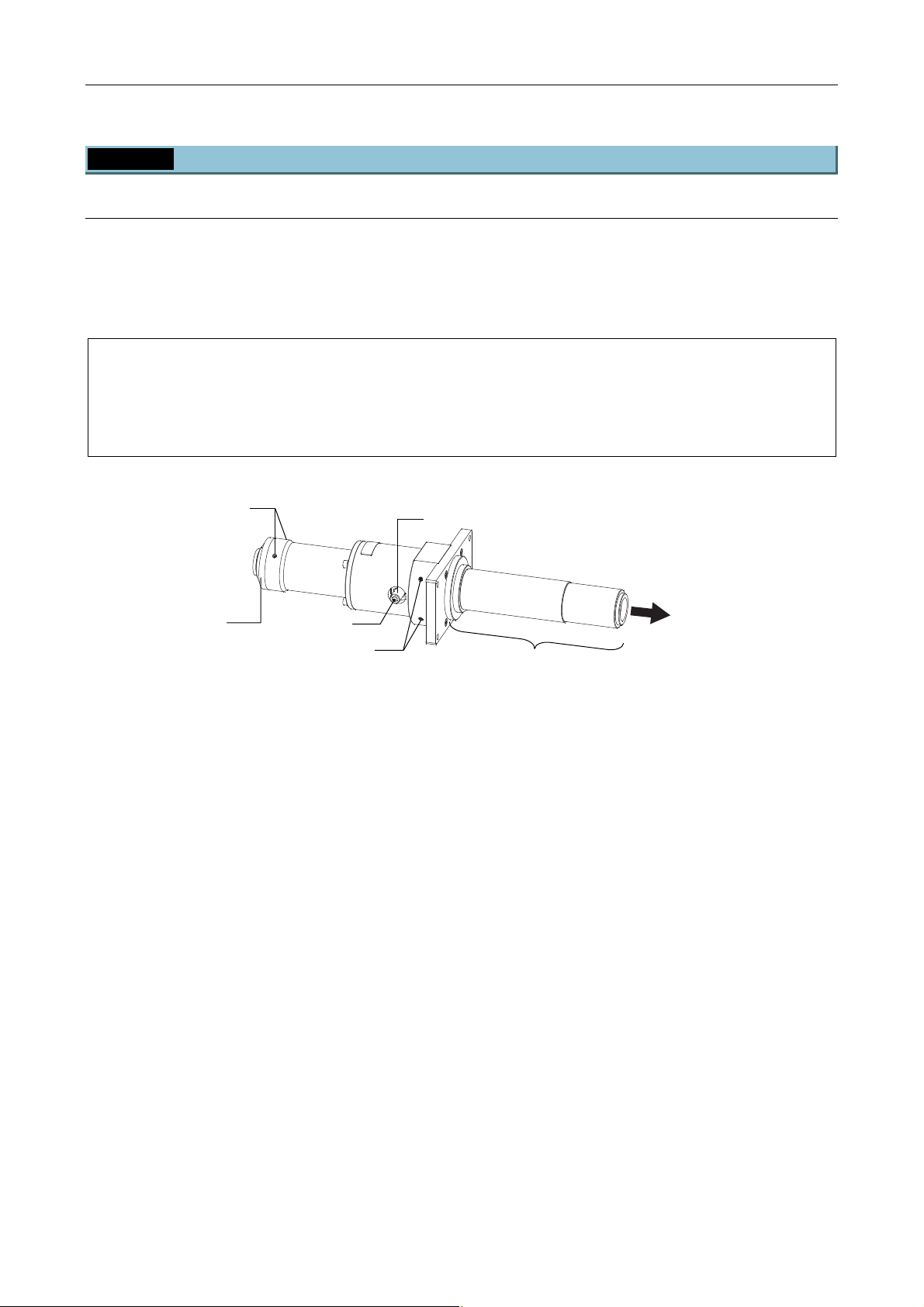
Chapter 1 System Configurations and Part Names
w
1.4 Name of Each Part
1.4.7 Related Product
TI-BPU back port unit
Adding a camera port by attaching the TI-BPU back port unit to the microscope base allows for a concurrent
image capture with two cameras.
Attach a C mount camera via a separate C mount adapter to the back port unit and perform focus adjustment
and centering.
Important
The dichroic mirror inside the filter cube is used to split the optical path, therefore, the dichroic mirror with
a poor flatness may cause lens effect due to a curved surface reflection, resulting in poor image
formation.
Use a dichroic mirror with higher flatness to be used for optical path split.
C mount adapter
clamp screws (two)
Focus knob
(separately available)
C mount adapter
Clamp scre
Centering screws (two)
Portion to be inserted into
the microscope
Figure 1.4-51
To eyepiece
1-64
Page 79
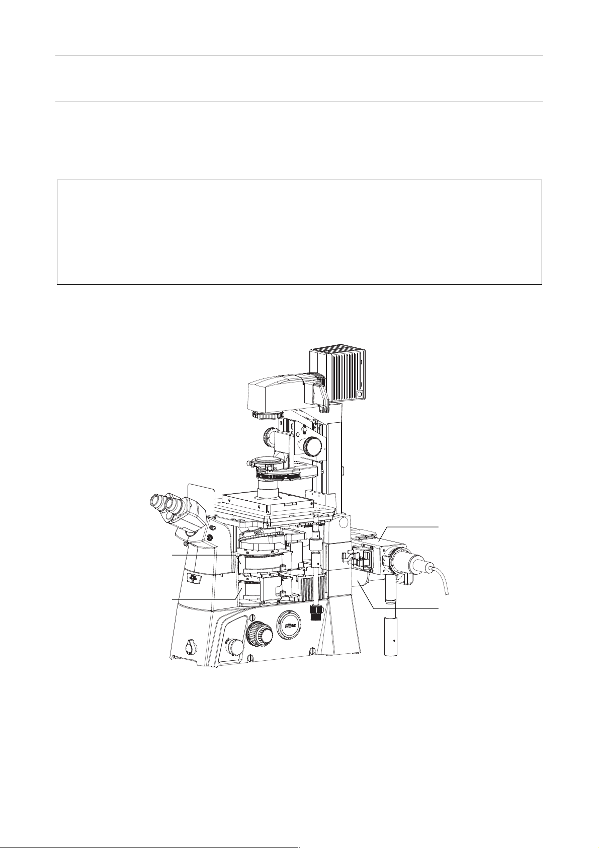
Chapter 1 System Configurations and Part Names
1.4 Name of Each Part
TI-BSUK70 70 mm stage up kit
By attaching the TI-BSUK70 70 mm stage up kit and doubly mounting the epi-fl filter turrets, you can attach
any of the TIRF illuminator unit/motorized TIRF illuminator unit/photo activation illuminator unit and TI-BPU
back port unit simultaneously.
The unit that can be attached to the upper or lower tier is selectable in accordance with the intended use.
Important
The condensing position will be misaligned when the TIRF illuminator unit/motorized TIRF illuminator
unit/photo activation illuminator unit is attached to the lower tier.
When attaching to the lower tier, embed the TI-TIRF stage up lens into the TIRF illuminator unit/motorized
TIRF illuminator unit/photo activation illuminator unit to correct the condensing position and provide the
optimum illumination performance.
Contact your own Nikon representative for details on the stage up lens.
The following figure shows the Ti-U with the stage up kit mounted, along with the TIRF illuminator unit on the
upper tier and the back port unit on the lower tier.
Epi-fl filter turret (upper tier)
Epi-fl filter turret (lower tier)
TIRF illuminator unit
Back port unit
Figure 1.4-52
1-65
Page 80
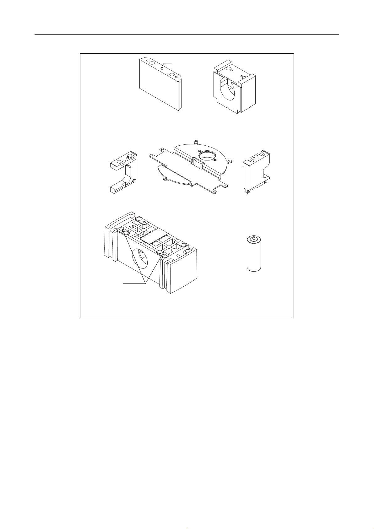
Chapter 1 System Configurations and Part Names
1.4 Name of Each Part
Positioning pin
Stage support block Nosepiece support block
Epi-fl filter turret
support block (left)
Positioning pin
Dia-illuminator pillar support block
TI-BSUK70 70 mm stage up kit
Shielding plate Epi-fl filter turret
Figure 1.4-53
support block (right)
Support pillar extension
1-66
Page 81
2
Preparations
2.1 Check Items and Tools
2.1.1 Required Items
Make sure you have all of the following items before starting.
• PC (complete set)
• PC-related devices
• Operating system
• Laser: Recommended laser (see Chapter 1, “System Configuration and Part Names”)
• Camera system (for TIRF and PAU image observation)
• Dichroic mirror (when the photo activation illuminator unit is used only.)
• One power cable
one cable for the four-laser module: 100 VAC area: 125 VAC 7 A or higher;
200 VAC area: 250 VAC 6 A or higher
one cable for the AOM controller: 100 VAC area: 125 VAC 7 A or higher;
200 VAC area: 250 VAC 6 A or higher
two cables for the laser PS rack: 100 VAC area: 125 VAC 7 A or higher;
200 VAC area: 250 VAC 6 A or higher, and
100 VAC area: 125 VAC 15 A or higher;
200 VAC area: 250 VAC 10 A or higher
CAUTION
Be sure to prepare power cables satisfying the ratings as specified above and complying with
the local safety standards. Extra care must be taken for the laser PS rack in particular, which
has a great current capacity.
1-67
Page 82
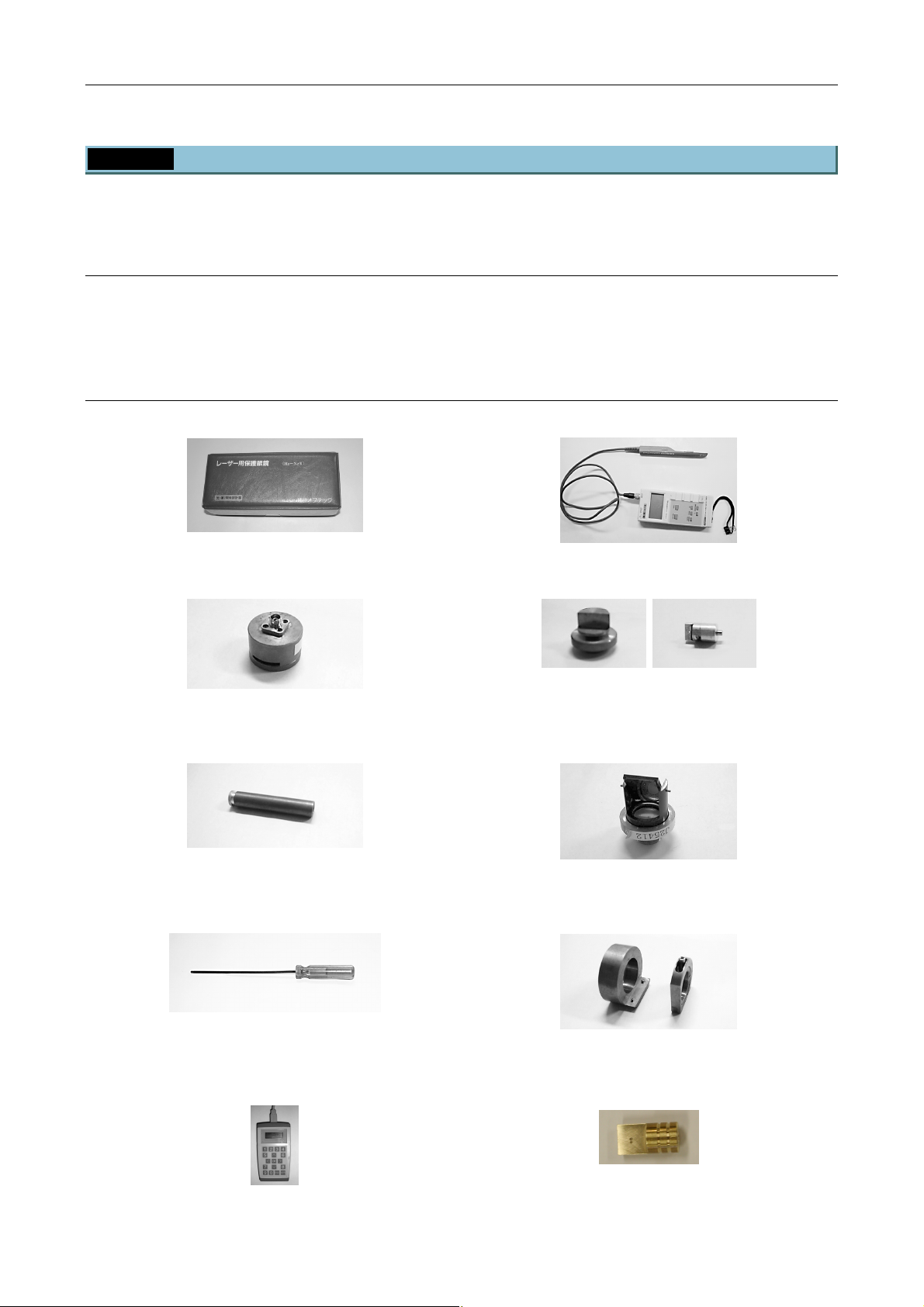
Chapter 2 Preparations
2.1 Check Items and Tools
2.1.2 Tools
The following are the tools required in the setup procedure. Before starting, make sure you have the
following tools required to set up the system.
General tools
• Allen wrench (mm, inch)
• Phillips screwdriver
• Fluorescent slide specimen (you can also use an HE-stained specimen)
Special tools
• Laser-protection goggles • Calibrated power meter
Figure 2.1-1 Figure 2.1-2
• Power measurement attachment • Dichroic mirror centering tool
Figure 2.1-3 Figure 2.1-4
• Coupler-centering tool • Centering tool for visual observations and mirror for
observing centering tool
Figure 2.1-5 Figure 2.1-6
• Nikon 2-piece M4 screwdriver set
(with red handles)
• Polarization orientation adjustment tool and
polarizer-equipped tool
Figure 2.1-7 Figure 2.1-8
• AOTF driver remote controller (for maintenance) • Centering tool (left: for LU4A)
* Two pieces of a type are required.
Figure 2.1-9 Figure 2.1-10
1-68
Page 83
Chapter 2 Preparations
2.2 Overview of Setup Procedure
2.2 Overview of Setup Procedure
1
2
3
4
5
Setting Up the PC and
Operation Software
(Chapter 3)
Setting Up the Microscope
(Chapter 4)
Laser Unit (Chapter 5)
Connection between the Laser
Unit and the Microscope
Confirmation and
(Chapter 6)
Check Sheet
(Chapter 7)
• Attaching the light source (TI-TIRF, TI-TIRF-E, or TI-PAU)
• Attaching the dichroic mirror (TI-PAU only)
• Attaching the epi-fl filter turret (TI-FLC, TI-FLC-E, or
TI-FLC-E/HQ)
• Assembling the microscope
• Attaching the field diaphragm unit
• Attaching the laser safety cover (TI-TIRF or TI-TIRF-E)
• Mounting the filter cubes
• Attaching the camera
• For two-laser unit and three-laser unit
• For three-laser unit EX
• For the four-laser module A
• For the four-laser PS rack
• Connection to the Shutter Unit
• Connection to the fiber light source (TI-TIRF, TI-TIRF-E, or
TI-PAU)
• Replacing the optical path switch mirror (if necessary)
• Laser safety check
• Check sheet entry
1-69
Page 84

3
Setting Up the PC and Operation Software
Using TIRF and PAU microscopy, images are observed on a monitor, via a camera attached to the
microscope camera port. TIRF images and laser port images from PAU microscopy cannot be observed
through the eyepieces. Make sure to set up the PC and operation software for the camera to be used.
1-70
Page 85
4
Setting Up the Microscope
4.1 List of Parts
The parts below have been added to the basic set of the Ti-E, Ti-E/B, Ti-U, and Ti-U/B.
The procedures for attaching sub-units and parts required for installing the TIRF-PAU illuminator are
described later in this section.
TIRF illuminator unit or motorized TIRF illuminator unit
Table 4.1-1
Unit Name of equipment Model Remarks
Ti-E
Microscope and
accessories
TIRF/
motorized TIRF
illuminator unit
Ti
Objectives for TIRF
Shutter Unit
AC adapter
Epi-fl filter turret for
epi-fl illumination
Episcopic light source
Stage ring
Stage up kit TI-BSUK70
Back port unit TI-BPU
TIRF illuminator unit
Fiber C1 single mode fiber
Straight fiber adapter TIRF2 S
Stage up lens
Ti-E/B
Ti-U
Ti-U/B
Apo TIRF 60xH/1.49
Apo TIRF 100xH/1.49
Plan Apo TIRF 60xH/1.45
Plan Apo TIRF 100xH/1.45
Plan Apo VC 60xH/1.4
Plan Apo VC 100xH/1.4
TI-LUSU
TI-LU4SU
AD-1260B
EA1050E-120
TI-FLC
TI-FLC-E
TI-FLC-E/HQ
Fiber optic light source
Lamphouse + power supply
26
32
TI-TIRF
TI-TIRF-E
TI-TIRF
Stage up lens
Use with the TI-DH dia-illuminator
100W.
Select the appropriate objective
for observation.
PC compatible
For TI-LUSU shutter unit
Three exclusive high-precision
filter cubes are supplied with the
TI-FLC-E/HQ as accessories.
Make sure to read the instruction
manuals for the product.
32 is made of glass.
TI-BSUK70 70 mm stage up kit is
required.
TIRF100 and TIRF60 - EPI40 are
interchangeable.
Straight fiber can be used
combined with the straight fiber
adapter.
When connecting an optical fiber
that has a straight tip, install a
straight fiber adapter to the
attachment.
When using the TIRF/motorized
TIRF illuminator unit on the lowest
step during stageup, install the
stage up lens to the
TIRF/motorized TIRF illuminator
unit. The TI-BSUK70 70 mm stage
up kit is required to stageup.
1-71
Page 86

Chapter 4 Setting Up the Microscope
4.1 List of Parts
Unit Name of equipment Model Remarks
Commerciallyavailable PC
Commerciallyavailable monitor
Commerciallyavailable TV camera
An adapter is required for
connection to the microscope port.
See “Chapter 5 Laser Unit” for
details on which lasers can be
mounted.
TIRF image
observation
Laser Unit
PC
Monitor
TV camera
Two-laser unit C-LU2
Three-laser unit C-LU3
Three-laser unit EX C-LU3EX
Four-laser module A LU4A
Filter slider cover
Ti laser safety kit
Filter cube port cover
retaining plate
Safety label
Protection plate
1-72
Page 87

Chapter 4 Setting Up the Microscope
Photo activation illuminator unit
Unit Name of equipment Model Remarks
Ti
Shutter Unit
AC adapter
Microscope and
accessories
Photo activation
illuminator unit
PA-GFP image
observation
Laser Unit
Epi-fl filter turret for
epi-fl illumination
Episcopic light source
Stage ring
Stage up kit TI-BSUK70
Back port unit TI-BPU
Photo activation
illuminator unit
Fiber C1 single mode fiber
PC Commercially-available PC
Monitor
TV camera
Two-laser unit C-LU2
Three-laser unit C-LU3
Three-laser unit EX C-LU3EX
Four-laser module A LU4A
Filter slider cover
4.1 List of Parts
Table 4.1-2
Ti-E
Ti-E/B
Ti-U
Ti-U/B
TI-LUSU
TI-LU4SU
AD-1260B
EA1050E-120
TI-FLC
TI-FLC-E
TI-FLC-E/HQ
Fiber optic light source
Lamphouse + power
supply
26
32
TI-PAU
Commerciallyavailable monitor
Commerciallyavailable TV camera
Use with the TI-DH dia-illuminator
100W.
PC compatible
For TI-LUSU shutter unit
Make sure to read the instruction
manuals for the product.
32 is made of glass.
TI-BSUK70 70 mm stage up kit is
required.
Switches PA-GFP/EPI. Requires an
optical path switch mirror.
An adapter is required for connection
to the microscope port.
See “Chapter 5 Laser Unit” for details
on which lasers can be mounted.
Ti laser safety kit
Filter cube port cover
retaining plate
Safety label
Protection plate
1-73
Page 88
Chapter 4 Setting Up the Microscope
4.2 Setup Procedure
4.2 Setup Procedure
4.2.1 Assembling Each Part and Attaching Them to the Microscope
Perform the steps below to assemble each part and attach them to the microscope.
Attach the light source (TIRF illuminator unit, motorized TIRF illuminator unit, or photo
1
activation illuminator unit).
⇒ Page 1-75
Attach the dichroic mirrors (photo activation illuminator unit only). ⇒ Page 1-77
2
Attach the field diaphragm unit. ⇒ Page 1-78
3
Attach the epi-fl filter turret. ⇒ Page 1-79
4
Assemble the remaining microscope parts. ⇒ Page 1-79
5
Attach the laser safety cover (TIRF illuminator unit or motorized TIRF illuminator unit
6
only).
Attach the light shielding plate. ⇒ Page 1-80
7
Attach the filter cubes. ⇒ Page 1-81
8
Attach the camera. ⇒ Page 1-81
9
⇒ Page 1-80
Affix the labels. ⇒ Page 1-82
10
1-74
Page 89
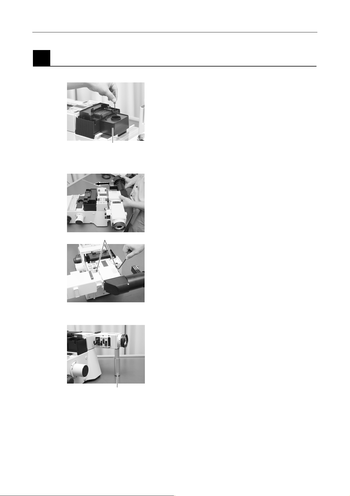
r
Chapter 4 Setting Up the Microscope
4.2 Setup Procedure
Attach the light source (TIRF illuminator unit, motorized TIRF illuminator unit, or photo
1
activation illuminator unit).
1. Remove the black cover on the center of the
microscope base.
(1) Using an Allen wrench, remove the two
screws securing the black cover.
(2) Remove the black cover.
Remove the black cover
Insert the light source
Figure 4.2-1
Four clamp screws
2. Attach the light source (TIRF illuminator unit,
motorized TIRF illuminator unit, or photo
activation illuminator unit) to the microscope main
body.
(1) Insert the light source into the guide on the
back of the microscope main body.
(2) Secure the light source by tightening the 4
clamp screws using the Allen wrench.
Figure 4.2-2
3. Attach the support pillar to the light source.
Support pilla
Figure 4.2-3
(1) Use an Allen wrench to loosen the clamp
screw securing the support pillar so that the
sliding part at the end slides freely.
(2) Screw the support pillar into the mounting
hole on the bottom of the light source to
attach it.
(3) Adjust the length of the support pillar so that
its tip touches the installation surface, and
then tighten the clamp screw with the Allen
wrench to secure it.
1-75
Page 90
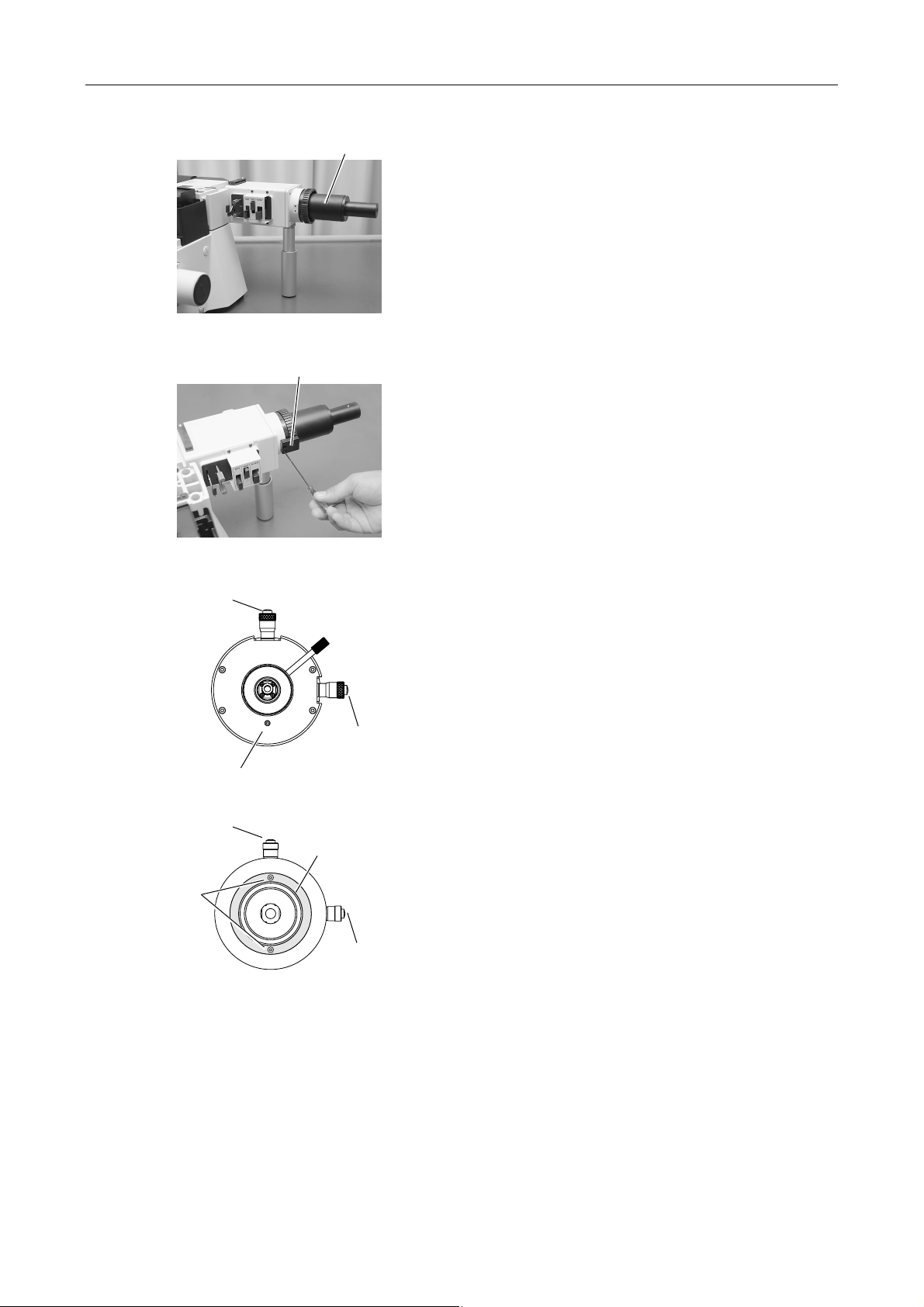
Chapter 4 Setting Up the Microscope
A
4.2 Setup Procedure
Laser position
adjustment knob
Laser position
adjustment knob
Two clamping
screws
Mercury episcopic light source adapter
Figure 4.2-4
Clamping hardware
Figure 4.2-5
Laser position
adjustment knob
Anchoring bolt
Laser connection port (TI-PAU)
nchoring ring
Laser position
adjustment knob
Laser connection port (TI-TIRF)
Figure 4.2-6
4. Connect the mercury episcopic light source
adapter (or mercury lamphouse) to the episcopic
light-source port (bayonet ring)
Connect the episcopic light source on the side
where you attached the support pillar in step 3.
For details about attaching the light source, see
the instructions of your mercury lamp power
supply or super-high pressure mercury lamp
power supply.
5. Attach the clamping hardware to the episcopic
light-source port.
Secure the clamping hardware by tightening the
two clamp screws using the Allen wrench.
The clamping hardware is provided to prevent the
PA-GFP irradiation attachment from being
removed by mistake. Be sure to attach the screw
for laser safety.
6. Remove the anchor on the laser side.
The laser position adjusting mechanism comes
equipped with an anchor for transportation. Be
sure to remove the anchor before turning the
laser position adjustment knobs.
Attempting to turn either of the knobs without
first removing the anchor may cause the
mechanism to malfunction.
(1) For TI-PAU:
The two laser position adjustment knobs are
loosened before transportation. Turn both
knobs gently clockwise until you feel
resistance, and then remove the anchoring
bolt.
(2) For TI-TIRF/TI-TIRF-E
The two laser position adjustment knobs are
loosened before transportation. Tighten both
knobs by turning them gently clockwise until
you feel resistance. Then, extract the two
locking screws and remove the brass
anchor ring.
1-76
Page 91
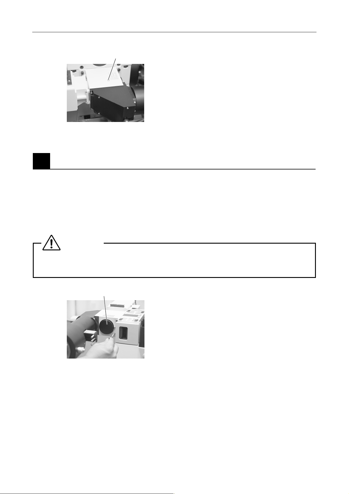
Chapter 4 Setting Up the Microscope
4.2 Setup Procedure
Anchoring bolt
Attach the dichroic mirrors (photo activation illuminator unit only).
2
It is necessary to attach a dichroic mirror (optical path switch mirror), which switches between laser light and
episcopic illumination, inside the photo activation illuminator unit. Since the attachment does not ship with a
mirror attached, you must attach one following the procedure below.
You can also change the light intensity ratio of laser light and episcopic illumination by switching the dichroic
mirror and operating the optical path switch lever.
Ordinarily, you should attach a total reflection mirror. When using a total reflection mirror, operating the
optical path switch switches between 100% laser light and 100% episcopic illumination.
WARNING
Figure 4.2-7
7. Remove the anchoring bolt from the optical path
switching module.
The optical path switching module comes
equipped with an anchor for transportation. Be
sure to remove the anchor before use.
1. Unscrew the anchoring bolt from the top of
the optical path switching module.
2. To plug the hole where the anchoring bolt
was, screw in the button bolt provided.
To prevent hazardous laser emission from the mirror replacement opening, turn off the laser
power before replacing mirrors.
Cap
Figure 4.2-8
1. Remove the retaining screw for the cap of the
mirror replacement opening using the Allen
wrench, and then remove the cap by turning it
counterclockwise.
1-77
Page 92
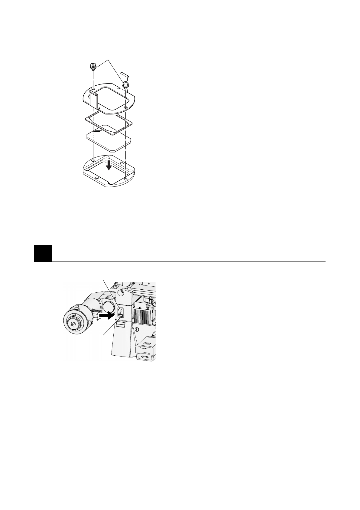
Chapter 4 Setting Up the Microscope
w
4.2 Setup Procedure
Holder plate locking screws
2. Remove the mirror unit from inside the
illuminator, and insert the dichroic mirror.
(1) When removing the mirror unit, pull out the
mirror switch lever, and then pull out the
mirror unit while holding the tab of the mirror
unit (magnetic lock).
Holder plate
(2) Remove the two holder plate locking
screws. Next, remove the holder plate and
flat spring to attach the mirror.
Flat spring
• Mirror size: 36 x 25.7 x 1
Mirror
(Place the
reflection
surface
downward.)
3. Attach the mirror unit in its original position, and
then close the cap of the mirror replacement
opening.
(1) There is a positioning hole on the mirror
unit. Securely attach the mirror unit to the
Mirror unit
Figure 4.2-9
illuminator to fit the pin on the main body.
(2) Screw the cap of the mirror replacement
opening until it is closed.
(3) Tighten the optical path switching module
screw using the Allen wrench, and secure
the cover.
Attach the field diaphragm unit.
3
Locking scre
Field diaphragm unit
Figure 4.2-10
1. Remove the rubber cap on the left side of the
microscope.
2. Insert the field diaphragm unit.
3. Tighten the locking screw using an Allen wrench,
and secure the field diaphragm unit.
C
A
U
T
IO
N
–
C
L
A
S
S
3
L
A
B
S
E
R
R
A
D
IA
T
IO
N
W
A
V
H
O
E
ID
N
E
O
X
P
P
E
O
N
S
U
R
E
T
O
T
H
E
B
E
A
M
V
O
R
S
IC
H
T
–
L
A
S
E
K
R
L
A
S
S
T
S
R
E
A
3
H
L
B
U
,
N
G
W
E
N
N
A
B
D
E
C
K
U
N
N
I
G
C
G
H
T
D
E
E
Ö
M
F
F
S
N
T
E
R
T
A
H
L
A
U
S
S
E
T
Z
E
N
1-78
Page 93
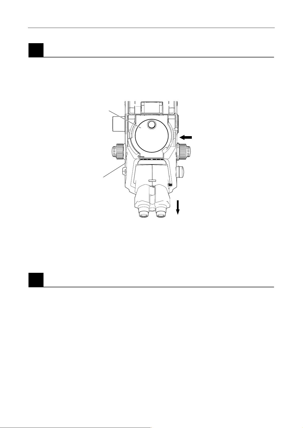
Chapter 4 Setting Up the Microscope
4.2 Setup Procedure
Attach the epi-fl filter turret.
4
Attach the epi-fl filter turret to the microscope main body.
Insert the epi-fl filter turret along the attachment groove from the right side of the microscope and
secure with screws on the left and right. (Use an Allen wrench. Note that the screws should be
tightened after the filter cube port cover is removed.)
Epi-fl filter turret
Insert from right
Filter cube port (and its cover)
Front side
Figure 4.2-11
When using the epi-fl filter turret in combination with the Ti-E or Ti-E/B, the protection plate (for
nosepiece) must be installed between the epi-fl filter turret and the nosepiece.
* For installation procedure, see Section 4.2.3, “Attaching the Laser Safety Kit.”
Assemble the remaining microscope parts.
5
Refer to the instruction manual included with the microscope main body before assembling the
remaining microscope parts.
1-79
Page 94
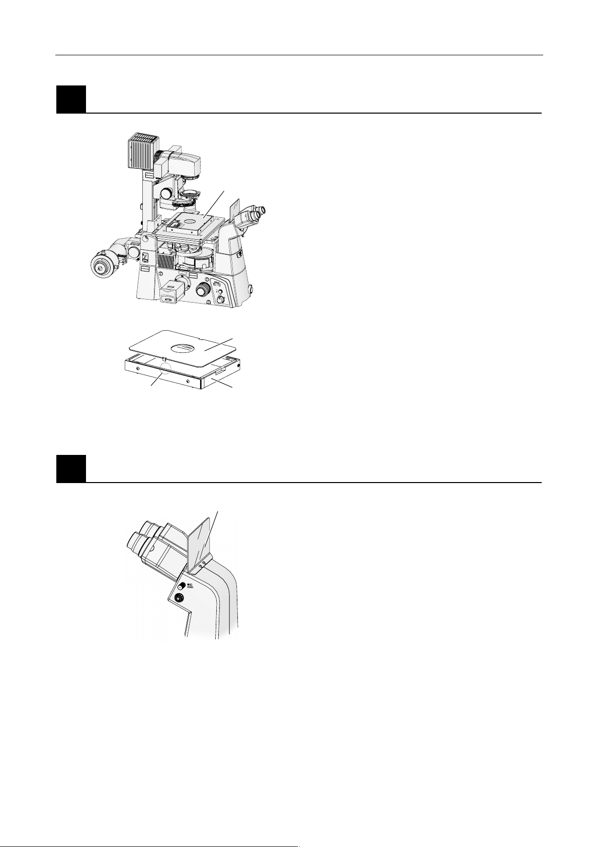
Attach the laser safety cover (TIRF illuminator unit or motorized TIRF illuminator unit only).
6
Safety interlock (both sides)
Chapter 4 Setting Up the Microscope
4.2 Setup Procedure
If you are using the TIRF illuminator unit or the
motorized TIRF illuminator unit, the motorized shutter
will not open unless the laser safety cover is attached
C
A
U
T
I
O
N
–
C
L
A
S
S
3
L
B
A
S
E
R
R
A
D
IA
T
IO
N
W
A
V
H
O
E
I
N
D
O
E
P
X
E
P
N
O
S
U
R
E
T
O
T
H
E
B
E
A
M
V
O
R
S
IC
H
T
–
LA
S
E
K
R
L
S
A
T
S
R
S
A
E
H
3
L
B
U
,
N
G
W
E
N
N
A
B
D
E
C
K
U
N
N
G
IC
H
G
T
D
E
Ö
E
M
F
F
S
N
T
E
R
T
A
H
L
A
U
S
S
E
T
Z
E
N
Laser safety cover
on the stage. Make sure it is attached in the prescribed
position.
1. Place the laser safety cover body on the stage,
and secure it by tightening the 4 screws with the
M
T
A
C
E
U
B
D
O
O
T
R
N
E
P
O
I
R
R
T
U
E
A
S
I
S
D
O
A
L
A
P
X
B
R
E
E
R
3
R
D
E
S
APERTURE
I
U
EMITTED
S
S
S
E
O
A
A
IS
V
O
L
L
A
P
C
HT
X
ECTIV
E
BJ
LIG
D
O
I
O
M
V
ASER
A
L
FRO
Allen wrench.
2. Connect the laser safety cover’s cable to the
safety-cover connector of the TI-LUSU shutter
CA
U
T
I
O
N
–
C
L
A
S
S
3
L
A
B
S
E
R
R
A
D
IA
T
IO
N
W
A
V
H
O
E
I
D
N
O
E
X
P
P
E
O
N
S
U
R
E
T
O
T
H
E
B
E
A
M
V
O
R
S
I
C
H
T
–
L
AS
E
K
R
LA
S
SS
T
R
E
A
H
3
L
B
U
,
N
G
W
E
N
N
A
B
D
E
CK
U
N
N
IC
G
H
T
G
D
E
E
Ö
M
F
F
S
NE
T
R
T
A
H
L
A
U
S
S
E
T
Z
E
N
A
V
O
ID
E
X
P
O
S
LA
U
R
S
E
E
R
L
IG
H
T
IS
F
E
R
M
O
I
T
M
T
E
T
D
H
I
S
C
A
A
UT
P
IO
E
N
R
–
T
C
U
L
R
A
S
E
S
3
LA
B
S
E
R
R
A
DIA
T
IO
N
W
A
H
V
O
EN
ID
O
E
PE
X
PO
N
S
U
R
E
T
O
T
H
E
B
E
AM
V
O
RS
IC
H
T
–
L
A
S
E
K
R
LA
S
TR
S
S
A
E
H
3
L
UN
B
,
G
W
E
NN
AB
D
E
C
K
U
NG
N
I
CH
G
T
E
D
Ö
E
F
M
F
S
NE
T
R
T
A
H
L
A
U
S
SE
T
ZE
N
ON
OFF
6V30W
12V100W
MAX.
unit.
3. Attach the cover on top of the body.
The interlock will close the motorized shutter of
the laser unit if the cover is removed during use.
* In the case of the photo activation illuminator unit,
Upper cover
you must attach a specimen cover on the stage
when using episcopic illumination or laser light.
* Touching the interlocking part or getting it wet could
cause it to malfunction.
Body
Figure 4.2-12
Attach the light shielding plate.
7
B
Figure 4.2-13
Light shielding plate
Using an Allen wrench, screw the light shielding plate
onto the eyepiece tube.
1-80
Page 95
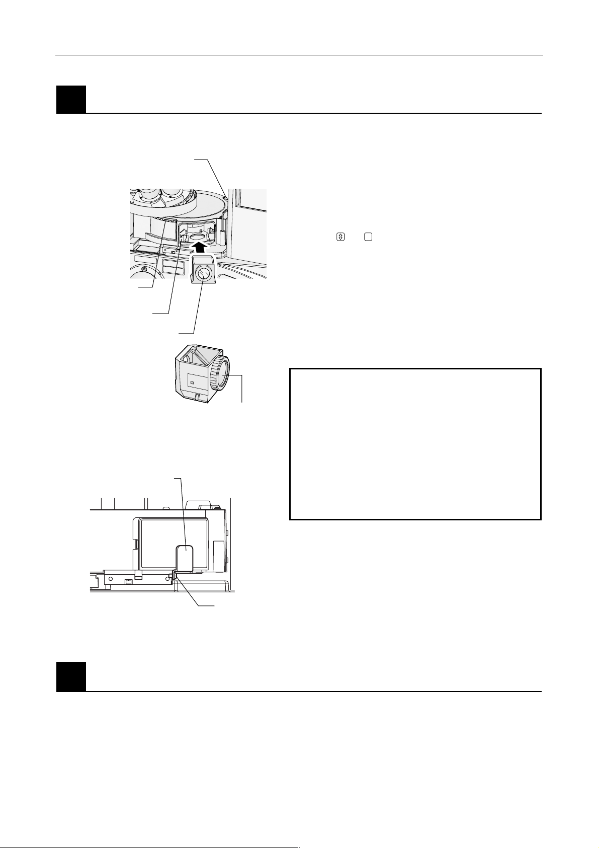
Chapter 4 Setting Up the Microscope
C
A
U
T
IO
N
–
C
L
A
S
S
3
B
L
A
S
E
R
R
A
D
I
A
T
IO
N
W
H
E
N
O
P
E
N
A
V
O
ID
E
X
P
O
S
U
R
E
T
O
T
H
E
B
E
A
M
V
O
R
S
I
C
H
T
–
L
A
S
E
R
S
T
R
A
H
L
U
N
G
K
L
A
S
S
E
3
B
,
W
E
N
N
A
B
D
E
C
K
U
N
G
G
E
Ö
F
F
N
E
T
N
I
C
H
T
D
E
M
S
T
R
A
H
L
A
U
S
S
E
T
Z
E
N
AVOID
EXPOSURE
LA
SER
LIGHT
IS
EM
ITTED
FROM
THIS
APERTURE
4.2 Setup Procedure
Attach the filter cubes.
8
You can attach up to six filter cubes in the epi-fl filter turret.
Excitation method
changeover ring
Address marking
Set the filter cube with its excitation filter
facing outside. (Do not set it in opposite way.)
Filter cube port cover
retaining plate
Indication of address
on the optical path
(position for ID sticker)
Filter cube
Figure 4.2-14
1. Remove the filter cube port cover, check the turret
address, and insert the filter cubes along the guide
groove.
2. Rotate the filter cube rotation control to display the
same address and affix an ID sticker that matches
the filter cube type.
Affix
or (a blank sticker that can be written
on freely) on spaces in which no filter cube is
inserted.
3. Re-attach the filter cube port cover.
Note: Excitation and barrier filters can be removed
4. Attach the filter cube port cover retaining plate.
from the filter cube and replaced with other
filters. (The filters are screwed into the filter
cube.)
Important
Excitation filter
• Three exclusive high-precision filter cubes are
supplied with the TI-FLC-E/HQ motorized epi-fl
filter turret as accessories. These filter cubes
are adjusted to the address of the epi-fl filter
turret. Make sure to attach the exclusive
high-precision filter cubes by matching the
inscribed addresses.
• If you use an excitation filter attached to the
excitation filter slider, attach the filter cube to
the excitation filter.
Fixing screw
Figure 4.2-15
Attach the camera.
9
Attach the camera to the camera port.
1-81
Page 96
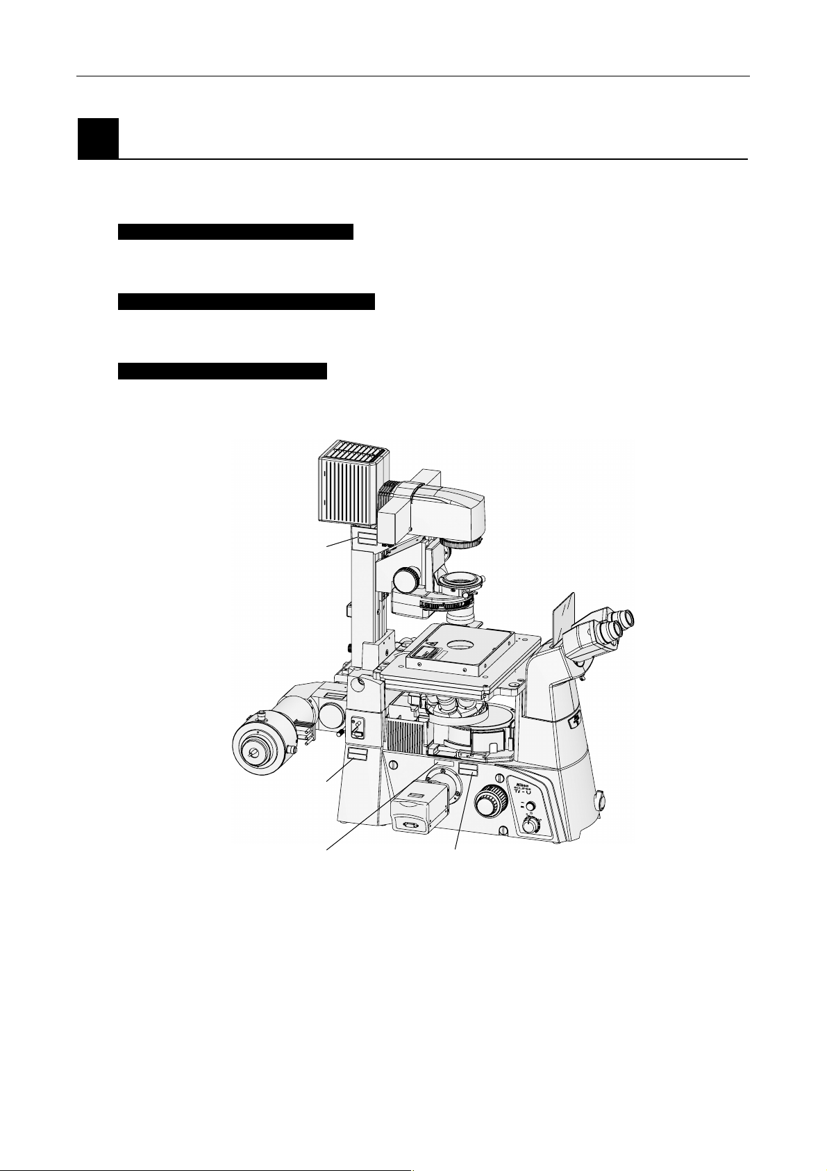
Chapter 4 Setting Up the Microscope
4.2 Setup Procedure
10
Affix the labels.
After confirming the safety of the laser (p.1-228 to 1-230), affix the specified warning labels to the
locations shown below.
Left side of microscope main unit
Affix “(7) IEC caution label - Class 3B area” on the left side of the microscope main unit, under the field
diaphragm.
Both sides of microscope main body
Affix “(7) IEC caution label - Class 3B area” and “(9) IEC aperture label 2” above the right and left ports
of the microscope main unit.
On 100W dia pillar illuminator
Affix
“(7) IEC caution label - Class 3B area” on the dia pillar illuminator 100W.
C
A
U
T
IO
N
–
C
L
A
S
S
3
L
B
A
S
E
R
R
A
D
IA
T
IO
N
W
A
V
H
O
E
ID
N
E
O
P
X
E
P
N
O
S
U
R
E
T
O
T
H
E
B
E
A
M
V
O
R
S
IC
H
T
–
L
A
S
E
K
R
L
S
A
T
S
R
S
A
E
H
3
LU
B
,
N
G
W
E
N
N
A
B
D
E
C
K
U
N
N
G
IC
G
H
T
D
E
Ö
E
M
F
F
S
N
T
E
R
T
A
H
L
A
U
S
S
E
T
Z
E
(7)
N
M
T
A
C
E
U
B
D
O
O
R
T
N
E
P
IO
R
R
T
U
E
S
IA
E
S
R
D
O
A
U
D
A
P
L
T
E
X
R
T
B
R
E
T
E
I
E
R
3
P
R
M
E
S
A
ID
U
E
S
S
S
E
O
S
A
A
I
V
O
IV
L
L
T
A
P
T
C
C
H
X
E
G
E
J
I
B
L
O
ID
R
O
E
M
S
V
O
A
A
R
L
F
C
A
U
T
IO
N
–
C
LA
S
S
3
L
A
B
S
E
R
R
A
D
IA
T
IO
N
W
A
V
H
O
E
ID
N
E
O
X
P
P
E
O
N
S
U
R
E
T
O
T
H
E
B
E
A
M
V
O
R
S
IC
H
T
–
L
A
S
E
K
R
LA
S
S
T
S
R
E
A
3
H
L
B
U
,
N
G
W
E
N
N
A
B
D
E
C
K
U
N
N
IC
G
G
H
T
D
E
E
Ö
M
F
F
S
N
T
E
R
T
A
H
L
A
U
S
S
E
T
Z
E
N
A
V
O
ID
E
X
P
O
S
U
LASER
R
E
LIGHT
IS
FRO
EM
ITTE
M
THIS
D
CA
A
UT
PER
ION
–
TUR
CL
ASS 3B
E
LAS
ER
RADIAT
IO
N W
AV
HE
OID
N
OPEN
EXPO
SUR
E
TO
TH
E BEAM
VO
RSICHT
–
L
ASER
KL
STRA
ASSE 3B,
HL
UN
G
W
EN
N A
BDEC
K
UN
NICH
G G
T D
EÖFF
EM
ST
N
ET
R
AH
L A
USSE
TZ
EN
(7)
ON
OFF
6V30W
12V100W
MAX.
(9) (both sides)
(7) (both sides)
Figure 4.2-16
1-82
Page 97
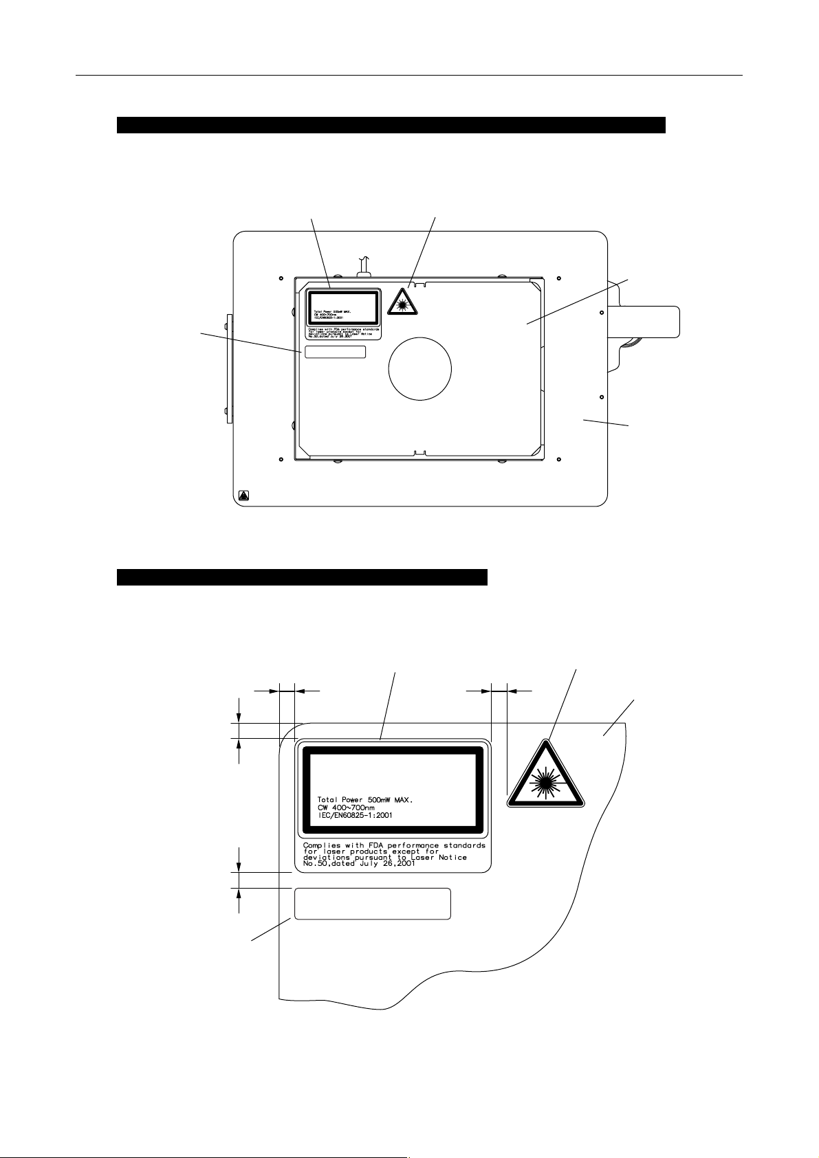
Chapter 4 Setting Up the Microscope
y
r
A
A
4.2 Setup Procedure
On the laser safety cover (TIRF illuminator unit or motorized TIRF illuminator unit)
Make sure that the following three warning labels at the rear left, when viewed from the Binocular
eyepiece tube: “(1) IEC warning label - laser hazard symbol”, “(2) IEC explanatory label - Class 3B
laser product”, and “(8) IEC aperture label 1” is affixed.
(8)
(2)
LASER RADIATION
AVOID EXPOSURE TO BEAM
CLASS 3B LASER PRODUCT
AVOID EXPOSURE
LASER LIGHT IS EMITTED
OBJECTIVE APERTURE
FROM
(1)
Figure 4.2-17
Top surface of stage (photo activation illuminator unit)
Make sure that the following three warning labels at the rear left, when viewed from the Binocular
eyepiece tube: “(1) IEC warning label - laser hazard symbol”, “(2) IEC explanatory label - Class 3B
laser product”, and “(8) IEC aperture label 1” is affixed.
Laser
cove
safet
Stage top surface
(2)
bout 5 mm
bout 5 mm
About 5 mm
(8)
LASER RADIATION
AVOID EXPOSURE TO BEAM
CLASS 3B LASER PRODUCT
AVOID EXPOSURE
LASER LIGHT IS EMITTED
OBJECTIVE APERTURE
FROM
About 5 mm
(1)
Stage top surface
Figure 4.2-18
1-83
Page 98
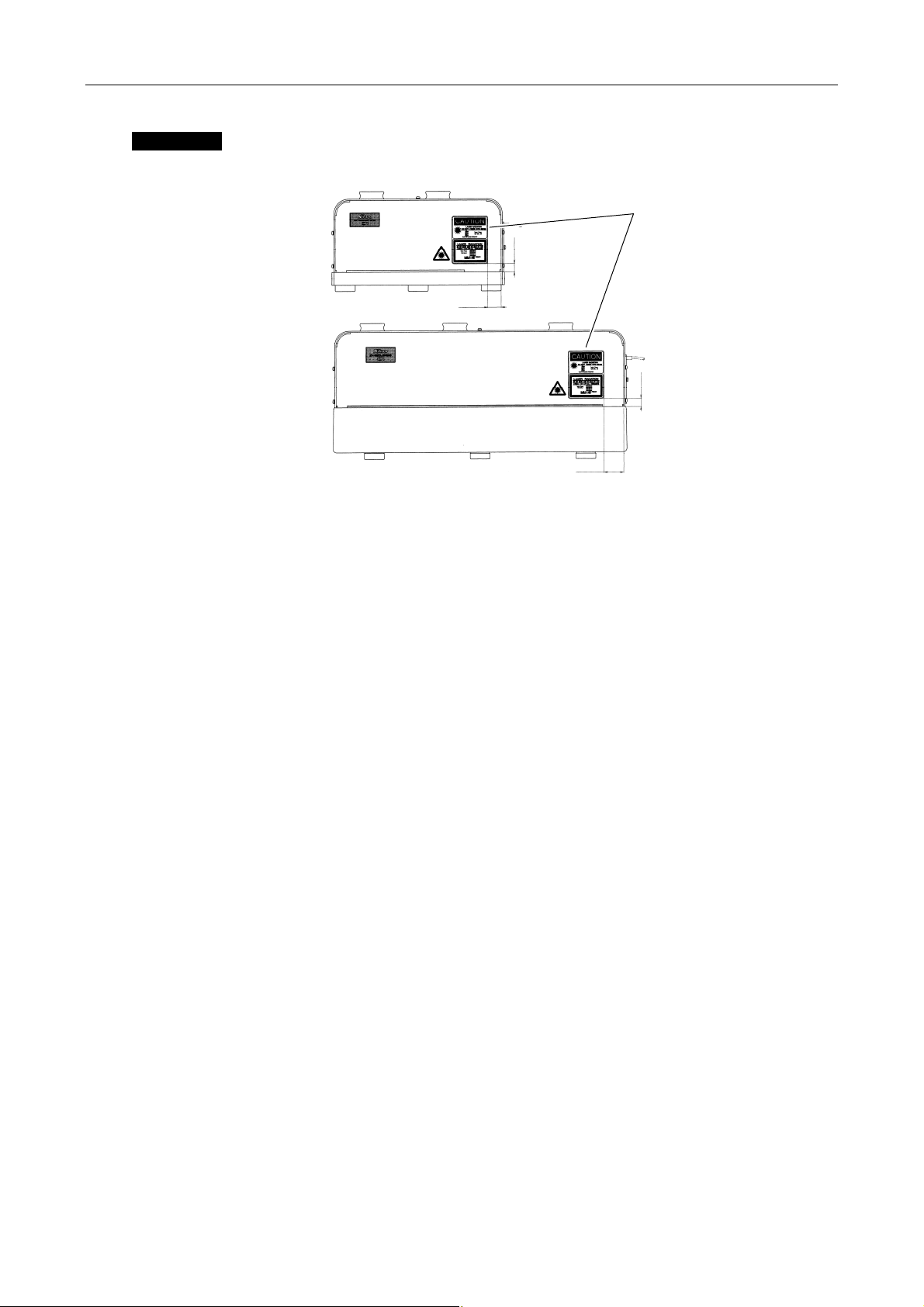
Chapter 4 Setting Up the Microscope
A
A
4.2 Setup Procedure
Laser unit
Remove the laser safety label if it is attached to the laser unit.
Remove the laser
safety labels.
bout 12 mm
About 20 mm
Figure 4.2-19
About 30 mm
bout 12 mm
1-84
Page 99
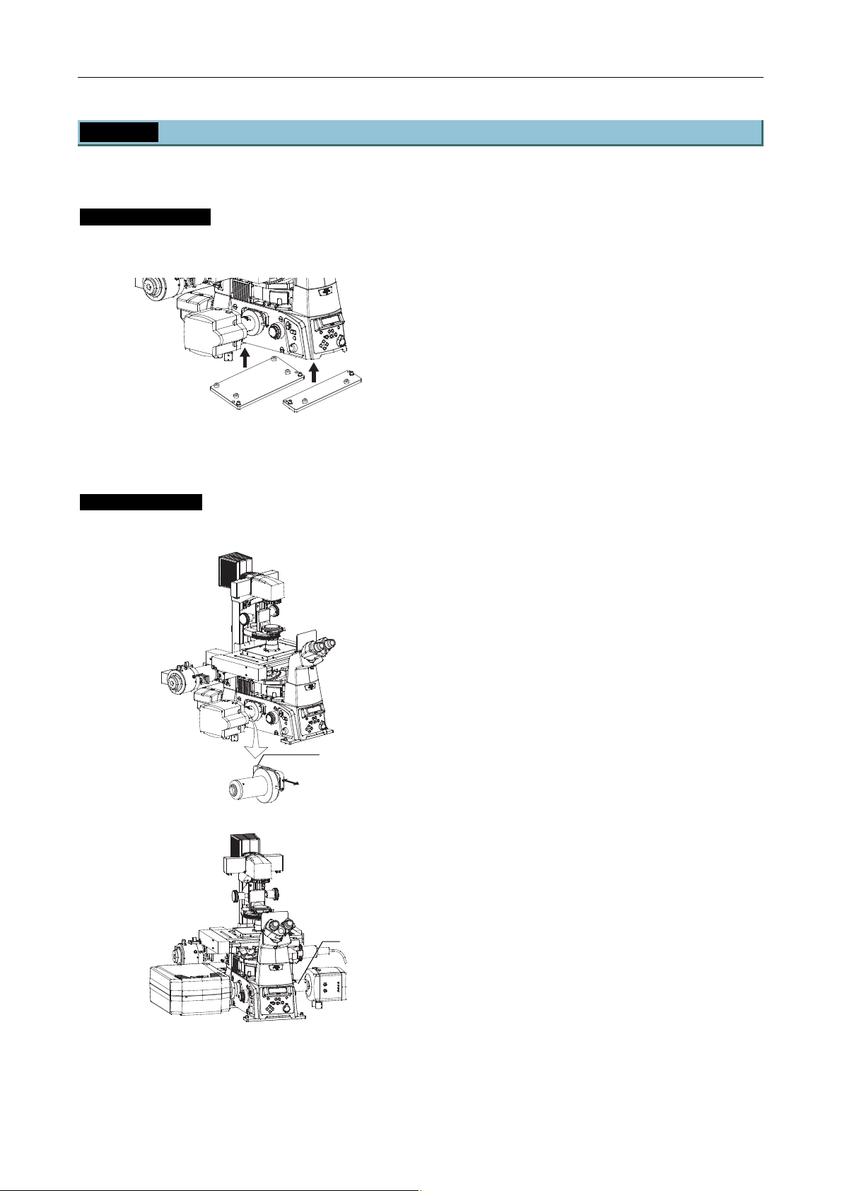
Chapter 4 Setting Up the Microscope
4.2 Setup Procedure
4.2.2 Attaching the N-STORM Kit
Install the following parts to the microscope to perform N-STORM microscopy.
Ti-E fixing plates
Attach plates to fix the microscope to the anti-vibration table.
Detach the front and rear rubber feet at the
bottom of the microscope and secure the fixing
plates (front and rear).
Install the microscope to the anti-vibration table
according to the inch holes or centimeter holes.
(Front) (Rear)
Ti-E fixing plates
Figure 4.2-20
3D-STORM port
Attach an optical system for N-STORM to the microscope.
Cylindrical lens
IN/OUT handle
OUT
IN
3D-STORM port
Detach the plastic cover on the side port of the
microscope and install the 3D-STORM port.
When using the port independently, install it in
the left side port. When using the port together
with the confocal microscope A1, install it in the
right side port.
Note: The 3D-STORM port cannot be installed
in the bottom port or the back port.
3D-STORM port
Combination of A1 and 3D-STORM port
Figure 4.2-21
1-85
Page 100
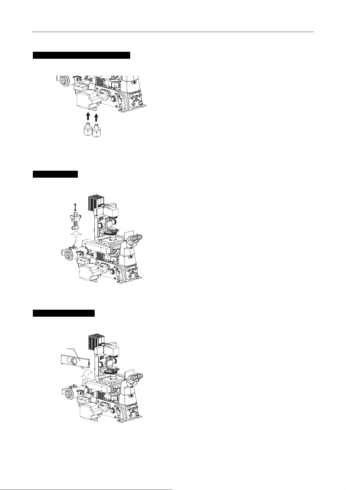
Chapter 4 Setting Up the Microscope
r
4.2 Setup Procedure
DSC support columns (2 pieces)
Attach supports to fix the camera to the anti-vibration table.
Screw the supports in the screw holes in the camera
(Andor iXon) body.
Secure the camera to the side 3D-STORM port of the
microscope and set the magnet base to ON.
DSC support columns
Figure 4.2-22
STORM slider
Insert the dedicated optical system into the TIRF optical system to perform N-STORM microscopy.
Detach the cover at the upper part of the laser
OUT
IN
STORM slider
introduction section in the motorized TIRF illuminator
unit.
You can see a slot to insert the STORM slider. Insert
the slider into the slot.
Then attach the cover to prevent the slider from
coming off.
Insert this slider during N-STORM microscopy, but
slide it out of the optical path in other cases.
Figure 4.2-23
Lambda plate slider
Insert an optical device for polarization adjustment to perform N-STORM microscopy.
Remove the stopper screw and detach the ND16 of
Lambda
plate slide
the motorized TIRF illuminator unit.
Insert the lambda plate slider into the same position.
Install the stopper screw.
Insert this slider during N-STORM microscopy, but
slide it out of the optical path in other cases.
Figure 4.2-24
1-86
 Loading...