

Nikon ECLIPSE E200 POL Instructions Manual

Microscope
ECLIPSE E200 POL
Instructions
M260E 04.2.CF.3(1/2)


1
Thank you for purchasing this Nikon product. This instruction manual is for the users of the Nikon Microscope ECLIPSE
E200 POL describing basic operation of the microscope.
To ensure correct usage, please read this manual thoroughly before using the microscope.
• It is prohibited to reproduce or transmit this manual in any form without the prior consent of Nikon.
• The instructions and specifications in this manual are subject to change without notice.
• Although every effort has been made to ensure the accuracy of this manual, if you find that any part of
this manual is unclear or incorrect, contact your nearest Nikon representative.
• Some ECLIPSE E200 POL microscope sets may come with different components and accessories from
those shown in this manual.
• Also read the manuals for the products used with the microscope, for example, the Nikon
photomicrographic equipment.
2
Safety Precautions
Warning and Caution Symbols Used in This Manual
Though Nikon products are designed to provide you with utmost safety during use, incorrect usage or disregard of the
instructions may cause personal injury or property damage and will lead to the forfeiture of all claims against warranty.
For your own safety, read the instruction manual carefully and thoroughly before using the product. Do not discard
this manual. Always keep it near the product for easy reference.
Inside this instruction manual, safety instructions are indicated with the symbols shown below. Be sure to follow the
instructions marked with these symbols for your safety.
Symbol Meaning
Disregarding instructions marked with this symbol may lead to death or serious injury.
Disregarding instructions marked with this symbol may lead to injury or property
damage.
Meaning of Symbols Used on the Equipment
The symbol appearing on the product indicates the need for caution at all times during use.
Always refer to the instruction manual and read the relevant instructions before manipulating any part to which the
symbol has been affixed.
Symbol Meaning
Caution! Biohazard
This symbol label attached on the stand reminds you of the following:
• WARNING: Contact of a living body sample to the microscope, presents a biohazard risk.
• To avoid biohazard contamination, do not touch the contaminated portion with your bare
hands.
• Decontaminate the contaminated portion according to the standard procedure of your
laboratory.
Caution for heat
This symbol label attached near the field lens unit (the lamp is set underneath the field lens
unit) reminds you of the following:
• Lamp and its surrounding areas (including the field lens unit) become very hot during and
immediately after illumination.
• Risk of burns. Do not touch the lamp or surrounding areas during and immediately after
illumination.
• Make sure the lamp and its surrounding areas have cooled sufficiently before attempting to
replace the lamp.
Caution
This symbol label attached near the AC inlet reminds you of the following:
• Check the input voltage before turning on the microscope.
(The input voltage is given on the "nameplate" and above the AC inlet.)
• If the input voltage shown differs from the local voltage level, do not turn on the microscope.
Do the following instead:
Different voltage on the nameplate Contact your nearest Nikon representative.
Different voltage above the AC inlet Change the input voltage setting; refer to P.35.
WARNING
CAUTION
Safety Precautions
3
VI
1. Intended use of the equipment
This microscope is intended mainly for use in microscopic observation of rock and mineral or polymer
materials or substance of living body, using polarized light illumination.
It is designed for the main purposes of analysis of the optical character, in laboratories or hospitals, of
such samples within the fields of mineralogy, high polymer chemistry, medicine.
2. Do not disassemble.
Disassembly may cause malfunction and/or electrical shock, and will lead to the forfeiture of all claims
against warranty. Do not disassemble any part other than those described in this manual. If you
experience any problem with the microscope, notify your nearest Nikon representative.
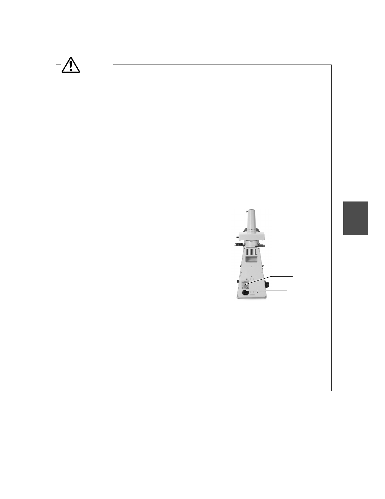
3. Check the input voltage.
The input voltage is indicated in two places at the rear of the microscope: on the nameplate and above
the AC inlet. Confirm that these input voltage indications correspond to the voltage provided in your
region. If not, follow one of the instructions below. The use of microscopes with the different input
voltage indications will cause overcurrent and overheating, which may result in fire or severe damage
to the microscope.
• If the voltage indication on the nameplate differs:
Î Do not plug in the microscope. Contact your nearest
Nikon representative.
• If the voltage indication above the AC inlet differs:
Î Refer to p. 35 and change the input voltage
setting before turning on the power switch.
• For the microscope with the nameplate showing
[100/110/120 V ~]:
The voltage can be set to: AC 100 V, 110 V or 120 V.
• For the microscope with the nameplate showing
[220/230/240 V ~]:
The voltage can be set to: AC 220 V, 230 V or 240 V.
4. Use the specified lamp, fuse, and power cord.
Use the specified lamp and fuse. Use the power cord provided. Using an incorrect lamp, fuse, or power
cord may damage the instrument or cause a fire. (Also see p. 50 on power cord.)
If using an extension cord, only use a cord that includes a protective earth (PE) wire.
• Specified Lamp
Halogen lamp 6 V-20 W (PHILIPS 7388 or OSRAM HLX64250) or
Halogen lamp 6 V-30 W (PHILIPS 5761)
• Specified Fuse
250 V, 1 A, time-lag low-breaking type, 5x20 miniature fuse x2
Input Voltage
Indications
WARNING
Safety Precautions
4
5. Heat at the light source
The lamp becomes hot during use. Do not remove the field lens unit while the lamp is on, and be sure
the lamp has been off for 30 minutes before touching it.
• When changing the lamp bulb, make sure that the lamp is cool enough to touch (the light should be
off at least 30 minutes).
• Do not touch the lamp while it is on or until the lamp has been off for 30 minutes, as doing so could
result in burns.
• Never bring cloth, paper or flammable volatile substances such as gasoline, petroleum benzine,
acetone, thinner, or alcohol near a hot lamp, as a fire could result.
6. Hazardous sample
This microscope is mainly for use in microscopic observation of rock and mineral or polymer materials
or substance of living body, using polarized light illumination.
When handling a living body sample, check to determine whether the sample is hazardous.
Handle hazardous samples according to the standard procedure of your laboratory.
If the sample is of an infectious nature, wear rubber gloves to avoid infection, and be careful not to
touch a sample. In the event of contact of a sample to the microscope, decontaminate the
contaminated portion according to the standard procedure of your laboratory.
1. Turn off power switch before assembling the microscope, replacing the lamp or fuse, and
plugging in or unplugging the power cord.
Turn off the power switch before you plug or unplug the power cord to prevent electrical shock or fire.
Also turn off the power switch and then unplug the power cord before assembling the microscope, and
before changing the lamp or fuse. To turn off the power, turn the power switch to {.
2. Keep the microscope free of moisture and foreign matter.
Keep the microscope free of moisture to prevent short circuiting that could result in overheating or
other malfunctions. If water splashes on the microscope, immediately turn off the power switch (turn
the switch to {) and unplug the power cord. Then, wipe off the water with a dry cloth. Short circuiting
can also result when foreign matter is trapped inside the microscope. If foreign matter or water has
entered the microscope, do not use the microscope and contact your nearest Nikon representative.
3. Disposal of the microscope
To avoid biohazard risk, dispose of the microscope as the contaminated equipment according to the
standard procedure of your laboratory.
WARNING
CAUTION
Safety Precautions
Notes on Handling the System
5
VI
Notes on Handling the System
(1)Installation
This microscope is a precision instrument. Using the microscope in an unfavorable environment
could result in malfunctions or degraded performance. Consider the following conditions when
choosing the installation location.
• Observation conditions are better if light from windows and bright room light can be avoided.
• Install the microscope in a location with a room temperature of 0° to 40°C and with a
maximum relative humidity of 85%. High temperature and humidity are to be avoided
because they promote mold growth and condensation, which may damage the microscope.
• Dirt and dust degrade optical performance and are to be avoided.
• Vibrations in the environment will degrade the image. Install the microscope in a location
free of vibrations.
• Install the microscope on a solid table and keep the microscope level.
• Select a layout that allows easy detachment of the power cord from the AC inlet of this
microscope in the event of emergency.
• This microscope emits a weak electromagnetic wave. Do not place a precision electronic
device near the microscope as precision could be degraded. Also, avoid placing a radio or TV
near the microscope as reception of sound and images may be hampered.
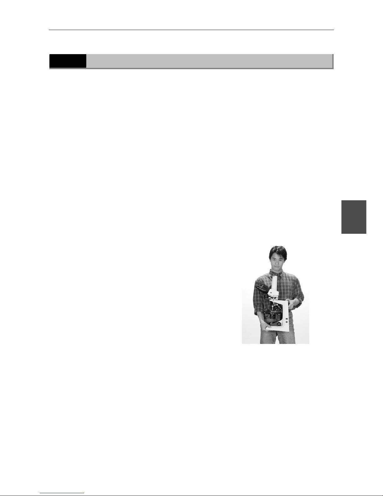
(2)Carrying the Microscope
This microscope is a precision instrument. Handle it
gently. Strong shocks and forcible operation will
damage the instrument. Shocks to the objectives,
especially, could degrade image precision.
• When carrying the microscope, hold it at its upper
rear and lower front ends.
• Do not hold the focus knobs, the eyepiece tube, or
the stage. These parts could easily come off and
could result in malfunctions.
(3)Handling the Lamp
Do not touch the glass part of the lamp with bare hands. Wear gloves or use a cloth when
handling the lamp so as not to leave fingerprints on the surface. Wipe off any fingerprints or
stains using a clean cloth moistened with alcohol. Fingerprints will etch into the hot surface of
the lamp and reduce the brightness, damage the lamp or reduce its service life.
Handle the lamp gently. Shocks and vibrations will damage the lamp or reduce its service life.
When changing the lamp, be sure that the contact is not damaged. If the contact is damaged,
the lamp may not light up or may overheat. Insert the lamp’s contact pins fully into the socket
holes. If the pins are loose, the lamp could come off or result in a contact failure, which will
cause overheating or smoke. Also, make sure that the field lens unit is securely attached.
Do not break the used lamps; instead dispose of them as special industrial waste or according to
the laws applicable to your municipal waste system.

Safety Precautions
Notes on Handling the System
6
VI
(4)Refocusing
When changing specimens using the refocusing
mechanism, gently lower the stage by hand taking
care not to hit the field lens with the condenser holder
(p. 15).
(5)Focus Knobs
Do not turn the right and left focus knobs
simultaneously in opposite directions. Do not turn the
coarse focus knob any further after the stage has
been moved up or down to its limit. These operations
will damage the focusing mechanism.
(The coarse focus knob has a protection device. The
knob turns freely for a while after it has reached its
upper limit.)
(6)Oil-Immersion Observation
Use only a minimum quantity of oil. If too much oil is applied, surplus oil could flow out to the
stage and the condenser which could lead to degraded performance.
When using petroleum benzine or absolute alcohol to wipe off immersion oil or
to clean the lenses, follow the instructions provided by their manufacturers.
Absolute alcohol and petroleum benzine are inflammable. Take great care when
handling them.
(7)Shipping Clamps
The microscope is held tightly by the clamps
during shipment. Be sure to remove the
clamps before use. For details, see p. 35.
Make sure not
to hit the field
l
ens
.
Do not turn the knobs in opposite directions.
Shipping Clamps
Shipping Clamps Shipping Clamps
WARNING

Contents
7
Contents
Safety Precautions .............................................................................................. 2
I Nomenclature of Each Part............................................................................. 8
II Switches and Controls..................................................................................10
III A Quick Microscopic Procedure.......................................................................12
IV Microscopy (Detailed Procedure) ....................................................................14
V Miscellaneous Operations..............................................................................31
1 Oil-Immersion Observation ................................................................................... 31
2 Adjusting the Torque of the Coarse Focus Knob....................................................... 32
3 Upper Limit Bolt .................................................................................................. 33
4 Cord Hangers...................................................................................................... 33
VI Assembly ...................................................................................................34
1 Assembly ........................................................................................................... 34
1) Input Voltage Check ...................................................................................... 34
2) Removal of Shipping Clamps .......................................................................... 35
3) Attaching the Intermediate Tube ..................................................................... 36
4) Attaching the Eyepiece Tube and the Eyepieces................................................. 36
5) Attaching the Analyzer Slider.......................................................................... 37
6) Attaching the Objectives ................................................................................ 37
7) Attaching the Condenser ................................................................................ 38
8) Connecting the Power Cord ............................................................................ 38
9) Other Accessories ......................................................................................... 38
2 Replacement of Consumable Materials ................................................................... 39
1) Replacing the Lamp ....................................................................................... 39
2) Replacing the Fuse ........................................................................................ 41
VII Optical Characteristics..................................................................................42
VIII Troubleshooting tables .................................................................................44
IX Care and Maintenance..................................................................................49
X Technical Specifications ................................................................................50

8
Nomenclature of Each Part
I
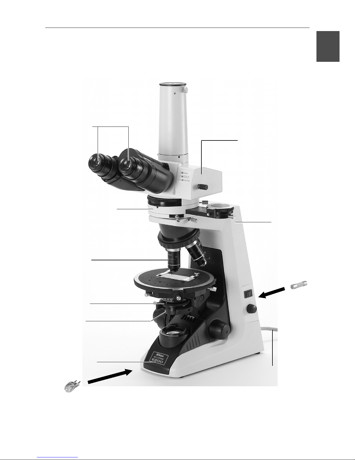
The microscope is made up of the following components.
(1) Basic unit
(2) Eyepieces
(3) Eyepiece tube
(4) Objectives
Objectives with various magnifying powers are available.
(5) Condenser
Used for condensing light. The condenser should be positioned slightly lower than its
upper limit.
Adjust the aperture diaphragm ring according to the objective.
(6) Polarizing intermediate tube
Used with the analyzer slider and the P-CL plate attached.
Equipped with the Bertrand lens.
(7) Polarizer
Adjust the vibration direction together with the analyzer before use.
(8) Field lens unit
Draw out the field lens unit when changing lamp.
(9) Lamp
Halogen lamp 6 V-20 W or 6 V-30 W is used.
(10) Fuse
Two 250 V 1 A time-lag low-breaking type fuses are used.
(11) Power cord
Use the power cord provided.
I Nomenclature of Each Part
9
I
(2)
Eyepieces
(6)
Polarizin
g
intermediate
t
ub
e
(4)
Ob
j
ectives
(5)
Condenser
(7)
Polarizer
(8)
Field lens unit
(9)
Lam
p
(3)
E
yep
iece tube
(1)
Basic unit
(10)
Fuse
(x2)
(11)
Power cord

10
Switches and Controls
II
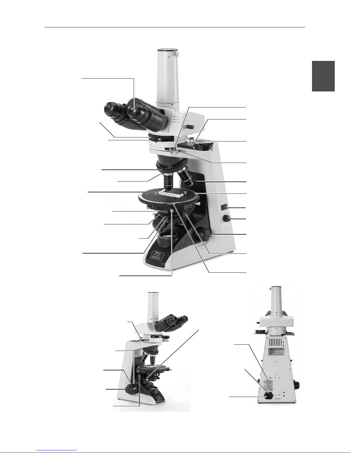
(1) Diopter ring
Adjust the diopter ring to
compensate for the
difference between your
right and left eyesight.
(2) Bertrand lens turret
Insert the Bertrand lens into
the optical path when
performing the conoscopic
observation.
(3) Bertrand lens focus ring
Used to focus on the
conoscopic image.
(4) Revolving nosepiece
Holds up to four objectives.
(5) Standard screw hole
mark
The marked objective screw
hole is the standard hole of
the nosepiece. Attach here,
the objective with the
highest magnification.
(6) Specimen clip
Holds the specimen.
(7) Condenser aperture scale
Indicates the numerical
aperture.
(8) Swing-out condenser
Swing-out the top lens when
performing the orthoscopic
observation with the 4x
objective.
(9) Condenser aperture
diaphragm ring
Usually, set to 70 to 80% of
the numerical aperture of
the objective.
(10) Polarizer
Insert into the bottom of the
condenser.
(11) Stage rotation clamp
screw
Fixes the stage in position.
(12) P-CL 1/4 λ and tint plate
Insert into the polarizing
intermediate tube.
(13) Eyepiece tube clamp
screw
Turn with the supplied
hexagonal wrench to fix the
eyepiece tube.
(14) Analyzer slider
Insert into the polarizing
intermediate tube.
(15) Intermediate tube clamp
screw
This is the eyepiece tube
clamp screw of the
microscope. It is used to fix
the intermediate tube in
place.
(16) Orientation plate
Shows the vibration
directions of the polarizer
and the analyzer.
(17) Circular graduated stage
Rotates 360 degrees.
Equipped with the
graduations which equally
divides the circumference in
360.
(18) Power switch
Press the l side to turn on
the power and to light the
lamp. Press the { side to
turn off the power and to
distinguish the lamp.
(19) Brightness control dial
Turn clockwise to increase
the voltage to make the
viewfield bright. Turn
counterclockwise to
decrease the voltage and to
darken the viewfield.
(20) Fine focus knob
Used for focusing. There is
no coarse focus knob on the
opposite side of the
condenser focus knob.
(21) Condenser top lens
swing-out knob
Used to swing-out the top
lens of the condenser.
(22) Vernier
Enables to readout the
angles in 0.1 degrees.
(23) Bertrand lens centering
screw
Used to center the
conoscopic image.
(24) Coarse focus knob torque
adjustment ring
Used to adjust the tension
(torque) of the coarse focus
knob.
(25) Coarse focus knob
There are both coarse and
fine focus knobs on the side
with the condenser focus
knob.
(26) Condenser focus knob
Located on the same side as
the coarse stage focus knob.
(27) Condenser clamp screw
(28) Nameplate
Indicates the input voltage.
(29) Voltage selector (Fuse
holder)
Match with the voltage
provided in your region.
(30) AC Inlet
Plug in the power cord. Turn
off the power switch before
plugging in the power cord.
II Switches and Controls
11
II
(23)
Bertrand lens centerin
g
screw
(24)
Coarse focus knob
torque adjustment ring
(25)
Coarse focus knob
(20)
Fine focus knob
(26)
Condenser focus knob
(27)
Condenser clamp
screw
(28)
Name
p
late
(29)
Voltage selector
(Fuse holder)
(30)
AC Inlet
(1)
Dio
p
ter ring
(2)
Bertrand lens turret
(3)
Bertrand lens focus rin
g
(4)
Revolvin
g
nosepiece
(5)
Standard screw hole mark
(6)
S
p
ecimen clip
(7)
Condenser a
p
erture scale
(8)
Swin
g
-out condenser
(9)
Condenser a
p
erture diaphragm ring
(10)
Polarizer
Stage rotation clamp screw
(12)
P-CL 1/4 λ and tint
plate
(13)
Eyepiece tube
clamp screw
(14)
Anal
y
zer slider
(15)
Intermediate tube
clamp screw
(16)
Orientation
p
late
(17)
Circular graduated
stage
(18)
Power switch
(19)
Brightness control
dial
(20)
Fine focus knob
(21)
Condenser top lens
swing-out knob
(22)
Vernier
(11)
12
A Quick Microscopic Procedure
III
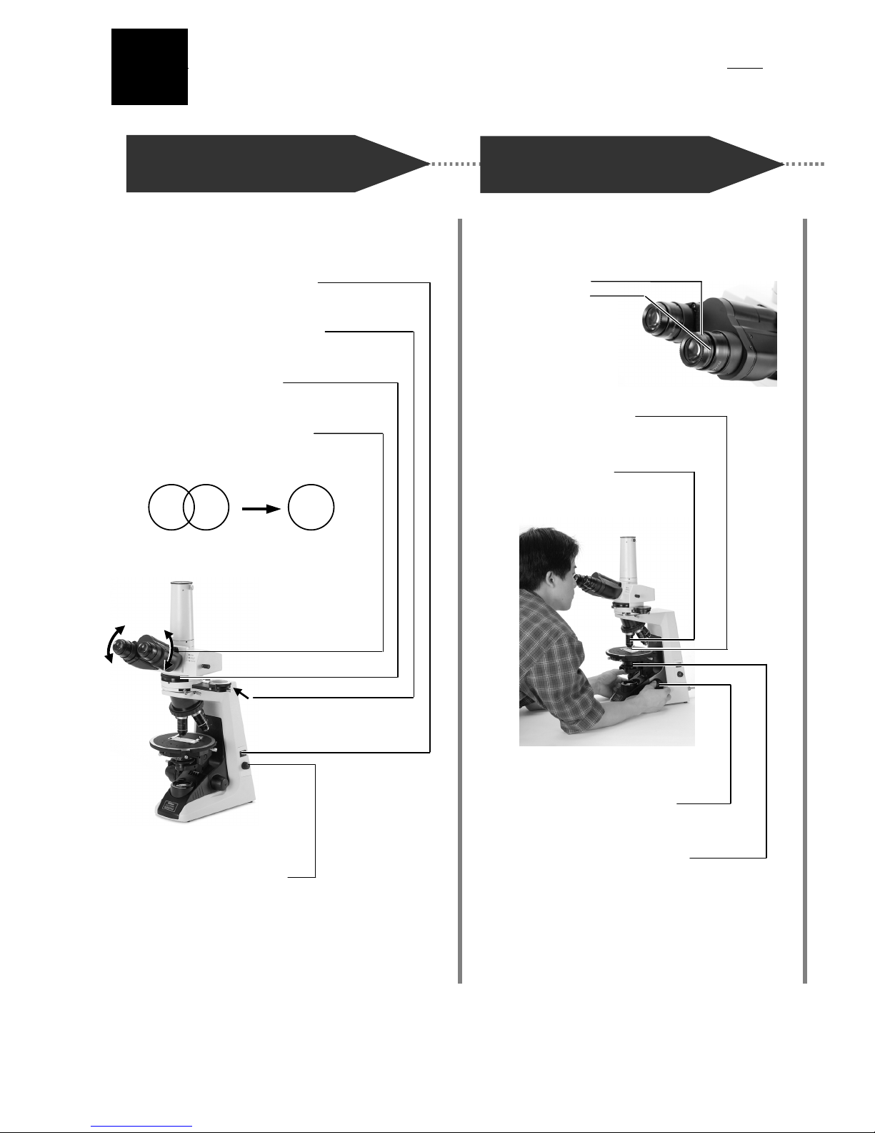
Turn on the lamp and adjust
interpupillary distance.
Focus with 10x objective.
1
Turn on the power switch.
2
Push the analyzer slider left.
3
Turn to position “0”.
4
Widen or narrow to merge
the viewfields into one.
5
Adjust brightness too.
Viewfields
1
Match the
bottom ed
g
e
of the
diopter ring
with the
engraved
base line.
2
Place specimen slide
on the stage.
(
Coverglass up.)
3
Swing the 10x in
the optical path.
Slightly lower the condenser
from its uppermost position.
Use this knob for focusin
g
.
III A Quick Microscopic Procedure
13
III
1
Use your right eye.
And focus on the crosshairs
with this ring.
2
Use your right eye.
3
Use your left eye.
And focus with this ring.
And focus on both the
crosshairs and the specimen.
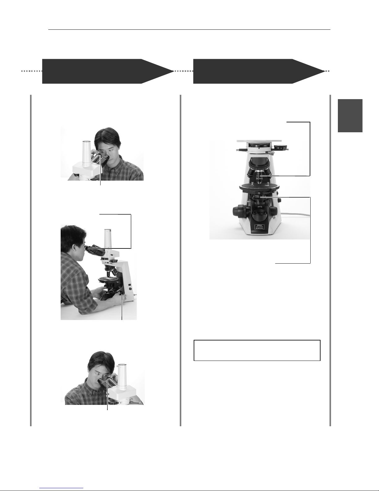
1
Check the magnifying power.
2
Move the ring to the
70-80% of the objective.
N.A.
3
Observe.
Turn off the power.
Wait till the microscope cools down before storing.
A
djust the diopter.
Magnify the image and
observe!
14
Microscopy (Detailed Procedure)
I
V
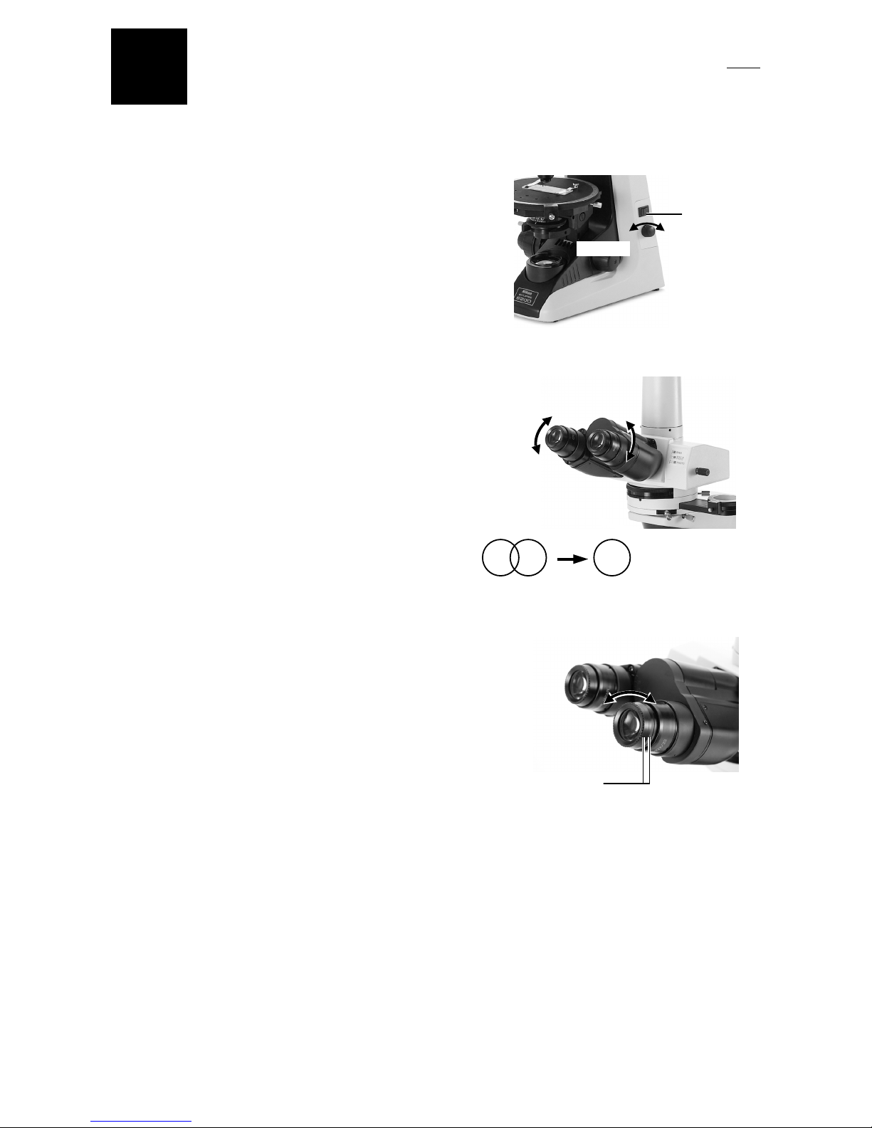
Lamp Illumination
1
Turn on the power switch (turn to |) and the lamp
will come on. Turn the brightness control dial to
adjust the brightness of the viewfield. (Turning the
dial clockwise increases the brightness; turning the
dial counterclockwise decreases it.)
Interpupillary Distance Adjustment
2
Adjust the distance between the eyepieces to
merge the right and left viewfields into one. (This is
an adjustment to match the distance between
eyepieces with the distance between your eyes).
Align the Diopter Ring with the Engraved Base Line
3
Turn the diopter ring on the right eyepiece to align
its bottom edge with the engraved base line. Turn
and align the diopter ring on the left eyepiece in
the same way.
4
Specimen Mounting
Place specimen slide on the stage with the coverglass facing upward and fix with the specimen
clips.
Power ON
Brightens.Darkens.
Viewfields
Merge the right
and left viewfields
into one.
Match the bottom
edge of the diopter
ring with the
engraved base line.
 Loading...