

Page 1

M362E 05.8.NF.1
Polarizing Microscope
ECLIPSE 50i POL
Instructions
Page 2

Page 3
Preface
Thank you for purchasing this Nikon product.
This instruction manual is intended for users of the Nikon’s Polarizing Microscope ECLIPSE 50i POL.
To ensure correct use, please read this manual carefully before operating the product.
• No part of this manual may be reproduced or transmitted in any form without the prior consent of Nikon.
• The contents of this manual are subject to change without notice.
• Every effort has been made to ensure the accuracy of this manual. If you find that any portion of this
manual is unclear or incorrect, please contact your nearest Nikon representative.
• This manual may describe products not included in the set purchased.
• Also be sure to read the manuals for any other products that you are using with this system (the super
high-pressure mercury lamp power supply, high-intensity light source, and such).
WARNING and CAUTION Symbols
Although Nikon products are designed to provide the utmost safety during use, incorrect usage or failure to follow the
safety instructions provided may cause personal injury or property damage. Damage or injury that may occur due to
mishandling is unwarranted. To ensure correct use, read the instruction manual carefully and thoroughly before using
the instrument. Do not discard the manual; keep it handy for easy reference.
Safety instructions within this manual are accompanied by the following symbols to highlight their importance. For
your safety, always follow the instructions accompanying these symbols.
Symbol Meaning
WARNING
CAUTION
Disregarding instructions accompanying this symbol may lead to serious injury or
death.
Disregarding instructions accompanying this symbol may lead to injury or property
damage.
1
Page 4
Preface
Meaning of symbols used on the equipment
The symbol appearing on the product indicates the need for caution at all times during use. Always refer to the
instruction manual and read the relevant instructions before manipulating any part to which the symbol has been
affixed.
Biohazard
This symbol on the microscope main unit calls your attention to the following:
•
Warning: If a specimen is spilled onto the microscope body, it may cause the danger of
biohazard.
•
To avoid biohazard contamination, do not touch the contaminated portion with your bare
hands.
•
Decontaminate the contaminated portion according to the standard procedure of your facility.
Caution for heat
This marking on the lamphouse of the Eclipse 50i POL calls your attention on the following;
•
The lamp and its surroundings (including the lamphouse) become very hot during and
immediately after the illumination.
•
Do not touch the lamp and its surroundings during and immediately after the illumination to
prevent the risk of burns.
•
Make sure that the lamp and its surroundings are sufficiently cool before the lamp
replacement.
2
Page 5

Safety Precautions
Take note of the following points to use this product safety and correctly.
1. Intended product use
2. Do not disassemble
3. Read the instructions carefully
WARNING
This microscope is intended primarily for microscopy and photomicrography of stones, rocks, minerals,
high-polymer materials, and biomedical materials using a polarized light illumination.
Besides, this microscope is intended for use in optical property analysis for laboratories, hospitals, and
other facilities in the fields of mineralogy, high polymer chemistry, and biomedicine.
Disassembling this product may result in electric shock or malfunctions. Damage or injury that may
occur due to mishandling is unwarranted.
Never attempt to disassemble any part other than the parts described in this manual. If you experience
problems with the product, contact your nearest Nikon representative.
To ensure safety, carefully read this manual and the manuals provided with any other equipment used
with this product. In particular, observe all warnings and cautions given at the beginning of each
manual.
4. Cautions about the power cord
Be sure to use the specified power cord. Using a wrong power cord may result in malfunctions or fire.
The product is classified as subject to Class I protection against electrical shock. Make sure it is
connected to an appropriate ground terminal (protective earth terminal).
Refer to Chapter 8 for the specified power cord.
To prevent electrical shock, always turn off the main power switch (press is to the “O” position) of the
product before attaching or detaching the power cord.
5. Cautions about heat from the light source
The lamp and its surroundings (including the lamphouse) become very hot during and immediately
after lighting.
• Do not touch the lamp and its surroundings during and immediately after lighting. They become
very hot and may cause burn injuries.
• Always mount the lamphouse cover when using the product.
• Make sure that the lamp and its surroundings are sufficiently cool before the lamp replacement.
• Do not allow cloth, paper, or highly flammable volatile materials, such as gasoline, benzine, paint
thinner or alcohol, to come near the lamphouse while the lamp is lit or within 30 minutes after
switching off the power. They become very hot and may cause fire or burn injuries.
6. Hazardous specimen
This microscope is intended primarily for microscopy of stones, rocks, minerals, high-polymer
materials, and biomedical materials using a polarized light illumination.
Check to determine whether the specimen is hazardous before handling. If the specimen is hazardous,
follow your standard facility procedures. If the specimen is a biomedical material and potentially
infectious, wear rubber gloves and avoid touching specimens. If the specimen is spilled onto this
product, decontaminate the portion according to the standard procedure of your facility.
3
Page 6

Safety Precautions
1. Isolate the products from the power source during assembly, connection/disconnection of cords,
CAUTION
lamp replacement, and maintenance
To prevent electric shock and/or malfunctions, always turn off the power switches of the product (press
to the “O” position) and unplug the power cord from the wall outlet before assembly, connecting or
disconnecting of cords, lamp replacement, and cleaning of the product and the objective.
2. Cautions in replacing lamps
To prevent burn injuries, wait at least 30 minutes after the lamp is turned off to give it sufficient time to
cool when replacing lamps. And, to avoid electric shock or malfunctions, never attempt to replace lamps
without turning off the power switches for the product and the peripheral devices (press them to the “O”
position). And then, unplug the power cords from the wall outlet.
Make sure the lamphouse cover is securely fitted to the lamphouse after replacing lamps. Never turn on
the lamp while the lamphouse cover is open.
When you dispose of the replaced lamp, do not break it up. Instead, dispose of the used lamp as special
industrial waste or dispose of it according to the local regulations and rules.
3. Use the specified lamp
The product's built-in power source is used for the halogen lamp that is a light source for the diascopic
illumination. A halogen lamp up to 6V-30W can be lit. But, always use the specified halogen lamp. Using
an unspecified lamp may cause malfunctions.
• Specified lamp: 6V-30W (PHILIPS 5761)
4. Prevent contact with moisture
Never allow water to come into contact with the product. And do not use the product in circumstances
where the product is splashed with water. Water splashed onto any component of this product may
cause short circuits, resulting in malfunction or abnormal over heat. If the product is subject to contact
with water, turn off the power switches for the product and the peripheral devices (press them to the
“O” position). And then, unplug the power cords from the wall outlet. And then, wipe off the water with
a piece of dry cloth. If water enters a component, immediately suspend use of this product, disconnect
the power cord from the outlet, and contact your nearest Nikon representative.
5. Do not place any object on top of the product
Do not place any object on top of the product or cover it with a piece of cloth or so on. The system
temperature will rise, resulting in malfunctions.
6. Cautions in assembling, installing, and carrying the product
• Take care to avoid pinching your fingers or hands during the product assembly and installation.
• Scratches or fouling such as fingerprints on optical components (such as lenses and filters) will
degrade microscope images. Be careful to avoid scratches or direct contact with the lenses and
filters when assembling the product.
• The main unit weighs approximately 11 kg. Grasp the main unit by the handle on the back of the
product and the recess at the base on the opposite side from the handle.
• Remove all attachments (if mounted) from the microscope before carrying the microscope.
• Do not install the product in a locker or cabinet.
4
Page 7

Safety Precautions
7. Cautions as to conditions for operation, transportation, and storage
CAUTION
The product must be operated, transported, or stored under the following conditions. Using or storing
the product in hot, humid locations may result in mold formation or condensation on lenses,
performance degradation, or malfunctions.
• Operating conditions: temperature (0 to 40°C), humidity (85% RH max., no condensation)
• Transportation/storage conditions: temperature (-20 to +60°C), humidity (90% RH max., no
condensation)
8. Remove any covers from the product before switching on.
Do not use the product while covered with a piece of cloth or so on, as this will result in abnormal heat
and fire hazards.
9. Cautions at to concerning long, sustained observations
To relieve fatigue resulting from long observation sessions, limit continuous observations to one hour.
Take at least 10- to 15-minute breaks between observation sessions. Adjust the layout of other
equipment and the height of your chair.
10. Disposal of the product
To avoid biohazard risks, dispose of the product as contaminated equipment according to the standard
procedure specified for your facility.
5
Page 8

Notes on handling the product
1. Handle with care
This product is a precision optical instrument. Avoid subjecting it to sudden impact and shocks.
Even relatively minor impacts are capable of affecting the precision of the objective.
Notes on handling the product
2. Weak electromagnetic waves
The product emits weak electromagnetic waves. Do not install the product near precision electronic
devices to avoid degrading their performance. If a TV or radio reception is affected, move the TV or radio
farther from the product.
3. Dirt on the lens
Scratches or fouling such as fingerprints on optical components (such as lenses and filters) will degrade
microscope images.
If these parts become dirty, clean them as described in “7. Care and Maintenance” at the end of this
manual.
4. Dirt on the lamp
Never touch the lamp with bare hands. Dirt or fingerprints on the lamp will result in uneven illumination
and reduce the service life of the lamp. Always wear gloves when handling lamps.
5. Installation location
This product is a precision instrument. The usage or storage in an inappropriate environment may result
in malfunctions or poor performance. Consider the following factors when selecting an installation
location:
• Select a vibration-free location. Install the product on a level surface.
• Install the product at least 10 cm away from walls.
• Choose a location less exposed to hazards in the event of collisions, earthquakes, or other potential
disasters. To keep the product from falling, use strong wire or other means if necessary to secure it
to the working desk or to another heavy, stable item.
• Avoid locations exposed to direct sunlight, locations immediately under room lights, and other bright
locations.
• Select a dust-free location.
• To avoid splashes, do not use the product near water.
• Make sure the ambient temperature is 0 to 40°C and humidity is 85% or less. And, to transport or to
store the product, the ambient temperature must be -20 to 60°C and humidity is 90% or less (with
no condensation). Using or storing the product in hot, humid locations may result in mold formation
or condensation on lenses, performance degradation, or malfunction.
• Do not install the product in a locker or cabinet.
• Select a layout that allows easy removal of the power cord from the product's AC inlet in the event of
an emergency.
• Room lights just above the product may enter the objective as extraneous light. If possible, switch
off room lights directly above the product when making observations.
• Do not use on a desk mat or the like.
6
Page 9

Notes on handling the product
6. Focusing knobs
• Never turn the focus knobs on the left and right sides of the product in opposite directions at the
same time. Doing so may damage the product.
• Turning the coarse focus knob past its farthest point will damage the product. Never use excessive
force when turning the knob.
7. Protect the ports from dust and extraneous light (when the trinocular eyepiece tube is attached).
To keep out extraneous light and dust, always attach the supplied cap to any port not currently in use.
7
Page 10

Expressions Used in This Manual
Microscope Eclipse 50i POL 50i POL
P-TB binocular eyepiece tube Binocular eyepiece tube
P-TT trinocular eyepiece tube Trinocular eyepiece tube
P-I intermediate tube Polarizing intermediate tube
P-N quintuple centering nosepiece Nosepiece or centering nosepiece
P swing-out condenser P swing-out condenser
PT polarizer Dia polarizer
LV-UEPI universal epi illuminator LV-UEPI or epi illuminator
YM-PO polarizer Epi polarizer
LV-LH50PC halogen precentered lamphouse Lamphouse
Expressions Used in This Manual
The product names and expressions used in this manual are given below.
The manual uses the following expressions:
Name of device
Expressions
Power supply device for the lamp Lamp power supply
P-ANH attachable mechanical stage Attachable mechanical stage
Y-TV TV vertical tube adapter TV vertical tube adapter
T-TV55 TV vertical tube adapter 0.55x TV vertical tube adapter 0.55x
DS camera head DS-5M Camera head
DS camera control unit DS-L1 DS-L1
DS camera cable Camera cable
8
Page 11

Contents
Contents
Preface ................................................................................................................ 1
WARNING and CAUTION Symbols ................................................................................... 1
Meaning of symbols used on the equipment .....................................................................2
Safety Precautions ................................................................................................ 3
WARNING ...................................................................................................... 3
CAUTION .......................................................................................................4
Notes on handling the product ......................................................................... 6
Expressions Used in This Manual ...................................................................... 8
1. Part Names.................................................................................................. 11
1.1 Components and Controls .................................................................................. 12
1.1.1 Front Left Side .......................................................................................... 12
1.1.2 Front Right Side ........................................................................................ 13
1.2 Microscope with the Epi Illuminator ..................................................................... 14
1.3 Rear Side ......................................................................................................... 15
1.3.1 Rear Side of the Microscope ........................................................................ 15
1.3.2 When the Lamphouse Cover Is Opened ........................................................ 15
2. Microscopy .................................................................................................. 16
2.1 Diascopic Bright-field Microscopy ............................................................................. 16
2.2 Orthoscopic Observation .................................................................................... 20
2.3 Conoscopic Observation ..................................................................................... 21
2.4 Episcopic Microscopy (with the Epi Illuminator Option)........................................... 22
2.5 Photomicroscopy ............................................................................................... 26
3. Individual Operations .................................................................................... 17
3.1 Power ON/OFF .................................................................................................. 29
3.1.1 Power Supply for the Microscope ................................................................. 29
3.1.2 Power Supply for the Epi Illuminator ............................................................ 29
3.2 Brightness Adjustment....................................................................................... 30
3.2.1 Adjusting the Brightness Control Knob ......................................................... 30
3.2.2 Adjustment Using the Preset Switch............................................................. 31
3.2.3 Adjustment Using the ND Filter IN/OUT Lever ............................................... 31
3.2.4 Adjustment Using the Brightness Control Knob on the Power Supply
for the Illuminator ..................................................................................... 31
3.2.5 Adjustment Using ND Filters on the Epi Illuminator ........................................ 32
3.2.6 Transmitted Image in the Episcopic Microscopy.............................................. 32
3.2.7 Camera Adjustment (Adjusting the Brightness of the Image on the Monitor) ..... 32
3.3 Optical Path Selection (for Trinocular Eyepiece Tube)................................................... 33
3.3.1 Light Distribution ....................................................................................... 33
3.3.2 Vertical Tube Adapter ................................................................................. 33
3.3.3 Disabling the Clicking of the Optical Path Selection Lever ................................ 33
3.4 Stage Vertical Movement (Focusing) .................................................................... 34
3.4.1 Prohibited Actions ...................................................................................... 34
9
Page 12

Contents
3.4.2 Knob Rotation and Stage Movement............................................................. 34
3.4.3 Number of Knob Turns and Distance of Stage Travel....................................... 34
3.4.4 Adjusting the Rotating Torque of the Coarse Focus Knob................................. 35
3.4.5 Coarse Focus Stopper Ring ......................................................................... 35
3.5 Stage Rotation.................................................................................................. 36
3.5.1 Stage Rotation .......................................................................................... 36
3.5.2 Attachable Mechanical Stage (Option) .......................................................... 36
3.6 Diopter Adjustment ........................................................................................... 37
3.7 Interpupillary Distance Adjustment ..................................................................... 37
3.8 Adjusting the Condenser Position ........................................................................ 38
3.9 Adjusting the Aperture Diaphragm ...................................................................... 39
3.9.1 For the Bright-field Microscopy and the Orthoscopic Microscopy ....................... 39
3.9.2 For Conoscopic Microscopy.......................................................................... 40
3.10 Selecting a Condenser ....................................................................................... 40
3.11 Adjusting the Field Diaphragm ............................................................................ 41
3.12 Setting a Filter on the Field Lens ......................................................................... 41
3.13 Centering the Objective ..................................................................................... 42
3.14 Oil Immersion Operation .................................................................................... 43
3.15 Water Immersion Operation ............................................................................... 44
3.16 Polarization Microscopy ...................................................................................... 45
3.16.1 Operation of the Polarizers .......................................................................... 45
3.16.2 Operation of the Analyzer ........................................................................... 46
3.16.3 Azimuth adjustment of the polarizer and analyzer.......................................... 47
3.16.4 Bertrand Lens Operation ............................................................................. 48
3.16.5 P-CL 1/4λ & Tint Plate ................................................................................ 49
3.17 Episcopic Microscopy ......................................................................................... 51
3.17.1 Switching the Episcopic Illumination ............................................................. 51
3.17.2 Field Diaphragm in the Epi Illuminator .......................................................... 51
3.17.3 Aperture Diaphragm in the Epi Illuminator .................................................... 52
3.17.4 Operating Filter on the Epi Illuminator .......................................................... 53
3.18 Image Capturing ............................................................................................... 54
3.18.1 Adjusting Light Intensity............................................................................. 54
3.18.2 Adjusting the Condenser............................................................................. 54
3.18.3 Confirming the Photomicrographic Range...................................................... 54
3.18.4 Confirming the Focus ................................................................................. 54
3.18.5 Making Adjustments to Keep out Ambient Light ............................................. 55
3.18.6 Anti-vibration Measures .............................................................................. 55
4. Assembly..................................................................................................... 18
4.1 System Configuration ........................................................................................ 56
4.2 Assembly Procedure .......................................................................................... 57
5. Replacing Consumables ................................................................................. 24
5.1 Replacing the lamp............................................................................................ 62
10
Page 13

Contents
6. Troubleshooting............................................................................................ 27
6.1 Optical System ................................................................................................. 65
6.2 Mechanical System ............................................................................................ 67
6.3 Electrical System .............................................................................................. 67
7. Care and Maintenance ................................................................................... 30
7.1 Lens Cleaning ................................................................................................... 68
7.2 Cleaning the Product ......................................................................................... 68
7.3 Disinfecting the Product ..................................................................................... 68
7.4 Storage ........................................................................................................... 69
7.5 Periodical Inspection (Fee Charged)..................................................................... 69
8. Specifications ............................................................................................... 32
8.1 Specifications ................................................................................................... 70
11
Page 14
p
1
Part Names
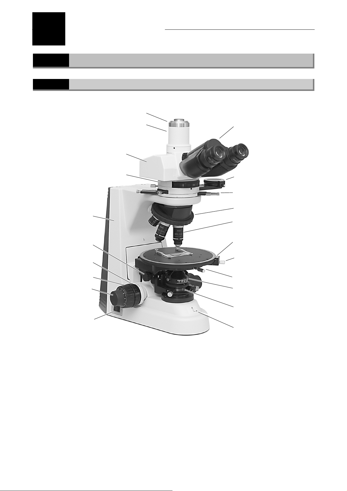
1.1
1.1.1
TV vertical tube adapter (option)
Trinocular eyepiece tube
Polarizing intermediate tube
Microscope main body
Condenser focus knob
Coarse focus torque
adjustment knob
Coarse focus knob
Fine focus knob
Power switch
Components and Controls
Front Left Side
C mount adapter (option)
Binocular part
Analyzer slider
P-CL 1/4λ & tint plate *1
Centering nosepiece
Objective
Vernier
Stage rotation clamp screw
Stage clamp screw
Condenser
(P swing-out condenser)
Dia polarizer
(bottom of the condenser)
Orientation
late
*1 It can be changed to the optional P-CS Senarmont compensator or P-CQ quartz wedge.
12
Page 15
Chapter 1 Part Names
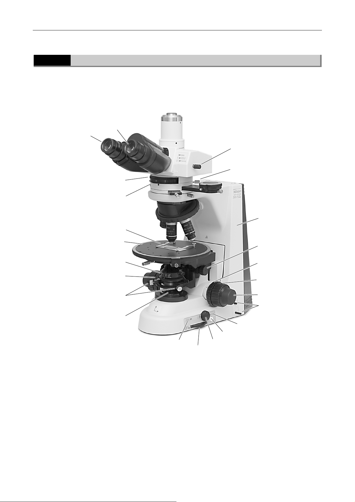
1.1 Components and Controls
1.1.2
Diopter adjustment
Bertrand lens focus ring
Circular graduated stage
Condenser aperture scale
Condenser centering screws
Front Right Side
Eyepiece
Bertrand lens turret
Specimen holders *2
Condenser aperture
diaphragm ring
Optical path selection lever
(only for the trinocular
eyepiece tube)
Bertrand lens centering screws
(both sides)
Microscope main body
Condenser focus knob
Coarse focus stopper ring
Coarse focus knob
Fine focus knob
ND filter IN/OUT levers
Field lens part
Preset brightness control
Preset switch
Power indicator
Field diaphragm control
Brightness control knob
*2 They are removed when the optional attachable mechanical stage is used.
13
Page 16
Chapter 1 Part Names
r
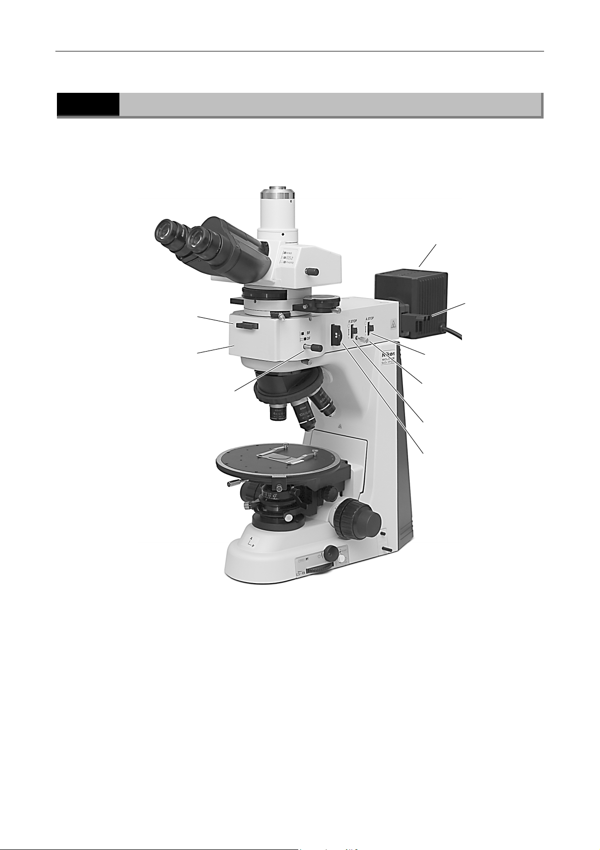
1.2 Microscope with the Epi Illuminator
1.2
Epi illuminator (LV-UEPI) Aperture diaphragm
Microscope with the Epi Illuminator
Dummy slide
Illumination selection lever
(bright-field/dark-field)
Lamphouse *3
Filter slider
open/close lever
Field diaphragm
centering screws (both sides)
Field diaphragm
open/close lever
Polarizer slider or
dummy slider
*3 The power supply for the epi illuminator is also required.
14
Page 17
Chapter 1 Part Names
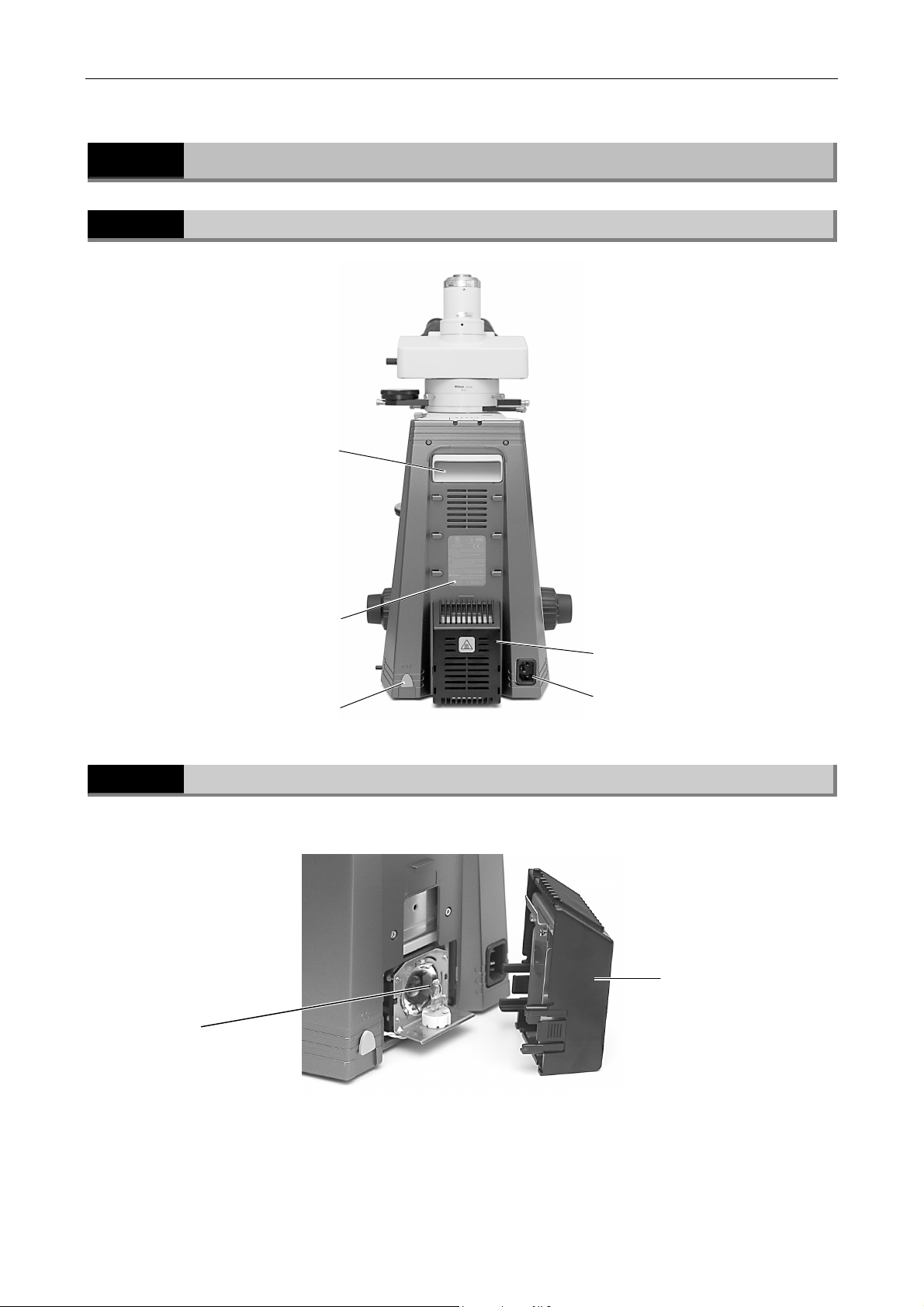
1.3 Rear Side
1.3
1.3.1
Rear Side
Rear Side of the Microscope
Handle
1.3.2
Halogen lamp
Input voltage indication
Tool
When the Lamphouse Cover Is Opened
Lamphouse
AC inlet
Lamphouse cover
15
Page 18
2
.
Microscopy
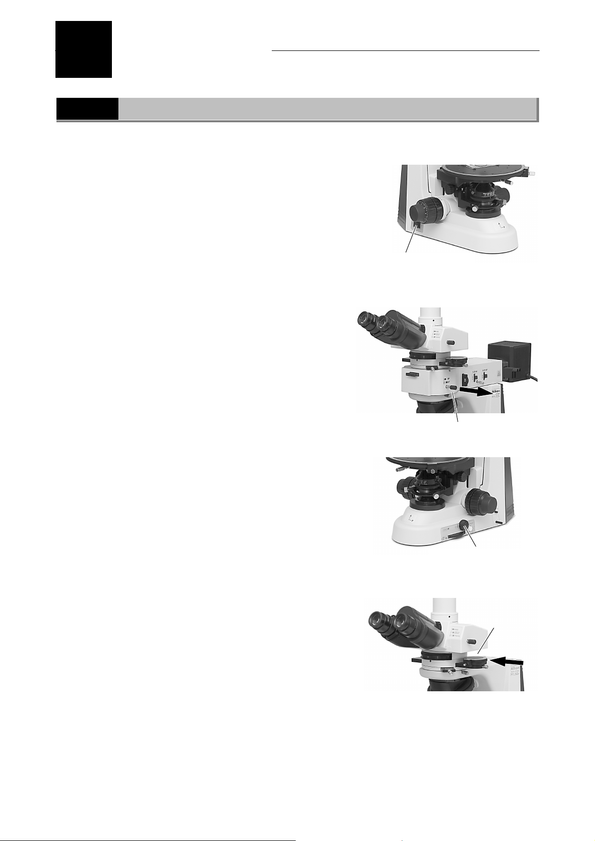
2.1 Diascopic Bright-field Microscopy
This section describes the diascopic bright-field microscopy using the built-in lamp of the
microscope.
1
2
Turn on the power.
When the microscope has power applied to it, the
power indicator on the right side of the microscope
is lit.
⇒ P.29
When the episcopic illuminator is
attached, turn off the episcopic
illuminator. And then, pull the
illumination selection lever to set
the dark-field position for it.
Push the power switch to
the “I” position.
3
4
⇒ P.51
Rotate the brightness control knob
to adjust the brightness.
Or, push the preset switch to apply the voltage that
wil make good color reproducibility.
⇒ P.30
Push in the analyzer slider on the
polarizing intermadiate tube to
remove the analyzer from the
optical path.
⇒ P.46
Set to the DF position.
Adjust the brightness, or
push the preset switch.
Remove the
analyzer from
the optical path.
16
Page 19
Chapter 2 Microscopy
p
2.1 Diascopic Bright-field Microscopy
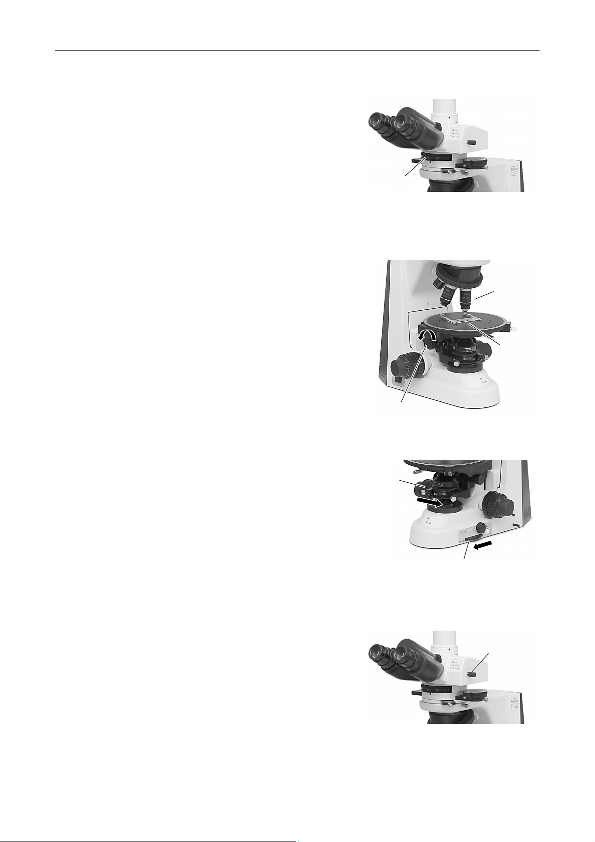
5
Move the Bertrand lens turret to
the “O” position to remove the
Bertrand lens from the optical
path.
6
7
8
9
10
⇒ P.48
Move the 10X objective into the
optical path.
Set the specimen in place with the
cover glass facing up.
Raise the condenser as high as it
will go.
Fully open the field diaphragm and
the condenser aperture
diaphragm.
Fully open the
aperture
diaphragm with
the aperture
diaphragm
knob.
Set the optical path to make
100% light go into the binocular
part when using the trinocular
eyepiece tube.
Remove the
Bertrand lens
from the optical
ath.
Raise the condenser
with the condenser
focus knob.
Set the 10X
objective.
Set the
specimen with
the specimen
holders.
Fully open the field
diapahram with the field
diaphragm control.
Set the optical path to
make 100% light go into
the binocular part.
⇒ P.33
17
Page 20
Chapter 2 Microscopy
2.1 Diascopic Bright-field Microscopy
11
12
13
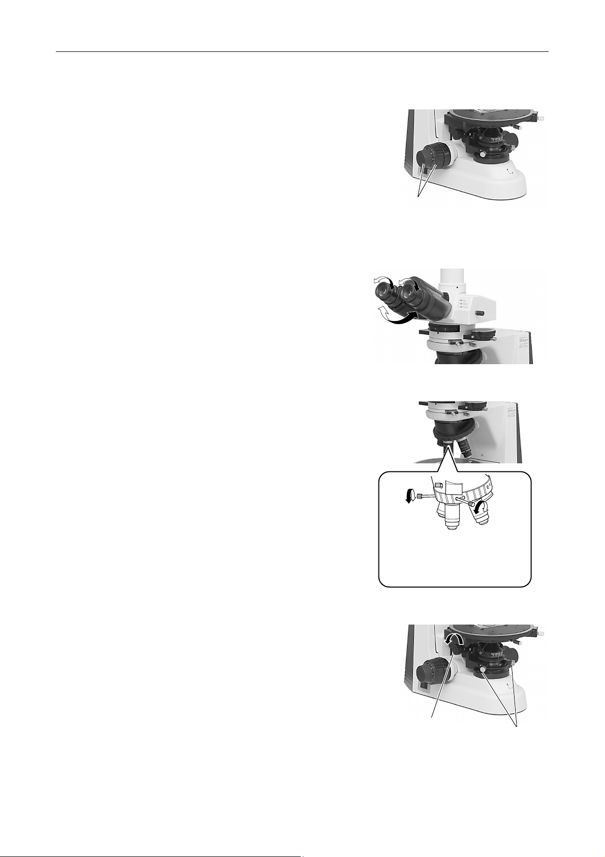
Focus on the specimen.
Fully loosen the coarse focus stopper ring.
⇒ P.34
Focus on the specimen
using the coarse focus
knob and the fine focus
knob.
Adjust the diopters and the
interpupillary distance.
⇒ P.37
Center the objective.
⇒ P.42
14
Special tools are provided with
the nosepiece. Insert the special
tools into the centering screw
holes on both sides to center the
objective.
Focus and center the condenser.
⇒ P.38
Move the condenser
with the condenser
focus knob.
Center the condenser
with the condenser
centering screws.
18
Page 21
Chapter 2 Microscopy
j
2.1 Diascopic Bright-field Microscopy
15
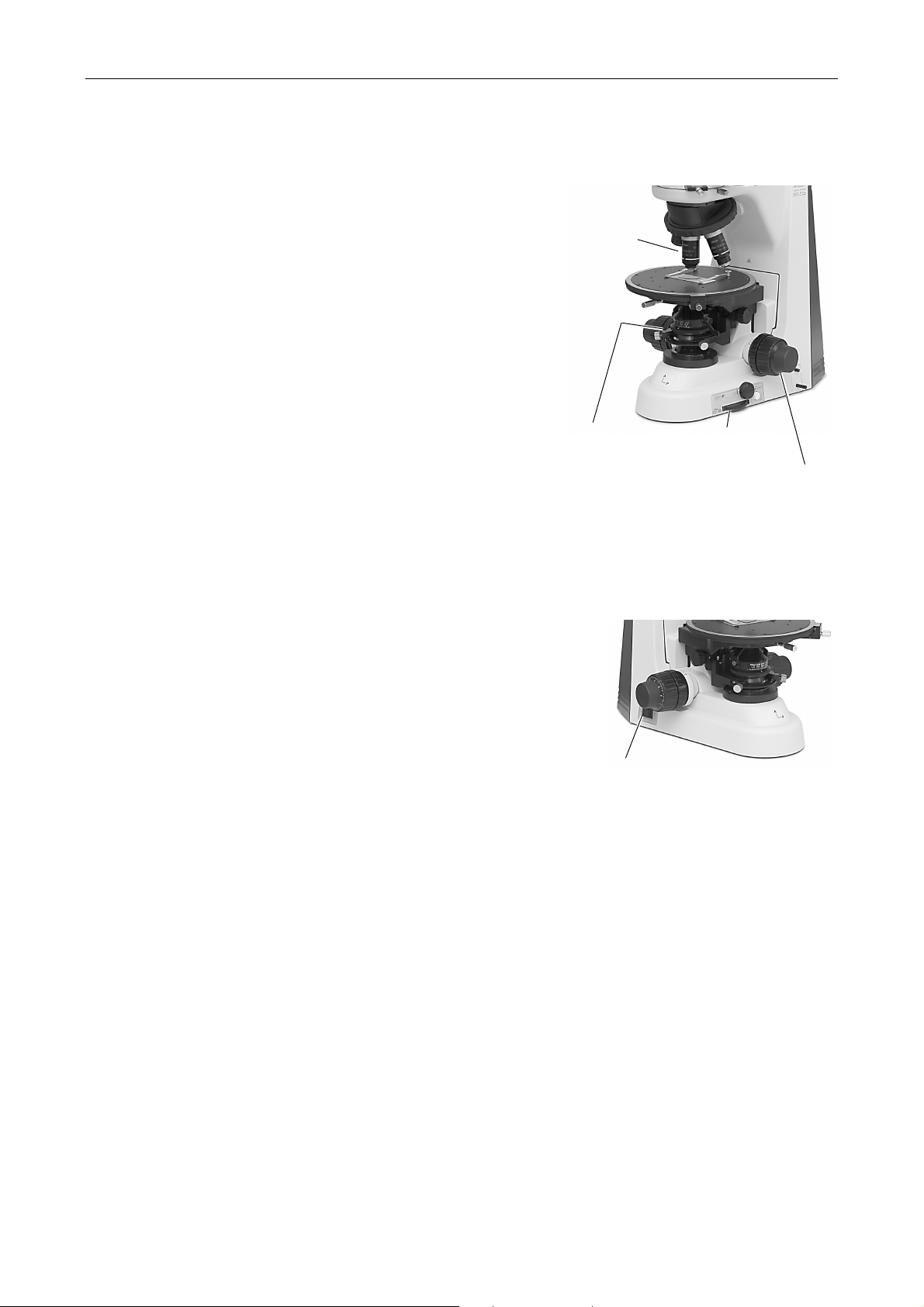
Switch to any desired objective
and view the specimen.
• Each time you change objectives, the field
diaphragm and the condenser aperture
diaphragm must be adjusted.
For the bright-field microscopy, the field aperture
should be adjusted so that its image
circumscribes the view field. And the condenser
aperture diaphragm should be 70% to 80% of
the numerical aperture of the objective.
⇒ P.39
⇒ P.41
• Focus on the specimen again using the fine focus
knob or the coarse focus knob.
⇒ P.34
• To use an oil immersion type objective or a water
immersion type objective, perform the oil
immersion or water immersion.
Switch to any
desired ob
Condenser aperture
diaphragm knob
ective
Field diaphragm
control
Focus on the specimen using
the coarse focus knob and the
fine focus knob.
16
Turn off the power after
completing the observation.
Push the power switch
to the “0” position.
19
Page 22
Chapter 2 Microscopy
2.2 Orthoscopic Observation
2.2
1
Orthoscopic Observation
This section describes the orthoscopic observation procedure. This is the characteristic
observation method of polarizing microscopes. In this method, the specimen is observed with
the polarizer and the analyzer placed in the optical path.
The shape of the specimen in the direction of the optical axis and its optical properties in the
direction of the thickness can be observed. The vibration direction of the light and the property
of the refraction can be measured with observations of light extinction or interference colors of
specimens and rotations of the stage.
Fosus on the specimen with the diascopic bright-field
microscopy. (Refer to “2.1 Diascopic Bright-field
Microscopy.”)
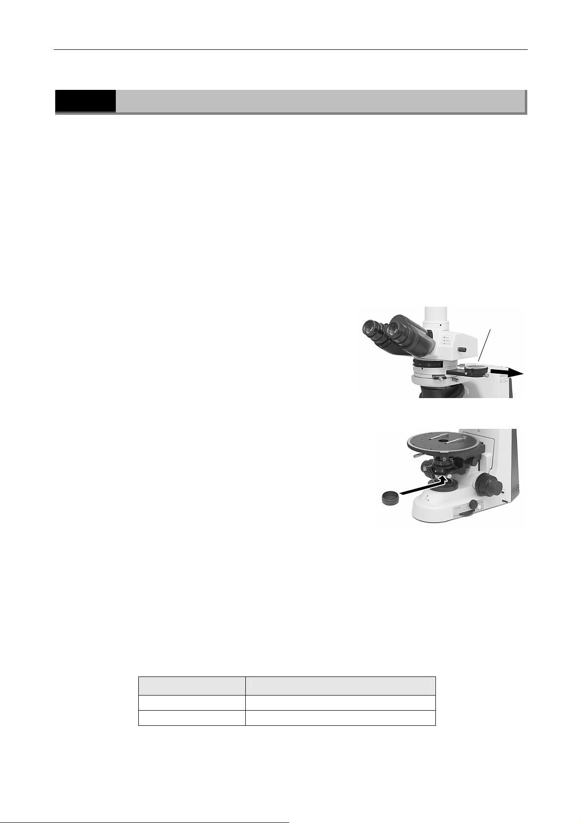
Pull the analyzer slider of the
2
intermediate tube to move the
Move the analyzer
into the optical path.
analyzer into the optical path.
Set the scale for the analyzer to the “0” position.
And, remove the Bertrand lens from the optical path.
Set the polarizer to the bottom of
3
the condenser.
Adjust the orientation of the
4
Set the polarizer.
polarizer and the analyzer.
⇒ P.47
After the adjustment, set the specimen again and focus
on it.
Perform the orthoscopic microscopy.
5
• You can measure the retardation in various range with the P-CL 1/4 λ & tint plate.(⇒ P.49)
• The condenser aperture diaphragm and the field diaphragm must be adjusted in the same
ways for the bright-field microscopy.
• The top lens of the P swing-out condenser is used depending on the magnification of the
objective.
Objective Top lens position of the swing-out condenser
10X or higher IN
4X or lower OUT
20
Page 23
Chapter 2 Microscopy
2.3 Conoscopic Observation
2.3
1
Conoscopic Observation
This section describes the conoscopic observation procedure. This is the characteristic
observation method of polarizing microscopes. In this method, the specimen is observed with
the polarizer, the analyzer, and the Bertrand lens placed in the optical path.
The specimen can be observed from various angles with diascopic light in the form of a single
image. However, the shape of the specimen itself is not visible with this observation. You can
distinguish the property of the specimen between uniaxial and biaxial and observe the optical
axial angle and optical characteristics of the specimen.
Perform the orthoscopic observation. (Refer to “2.2
Orthoscopic observation.”)
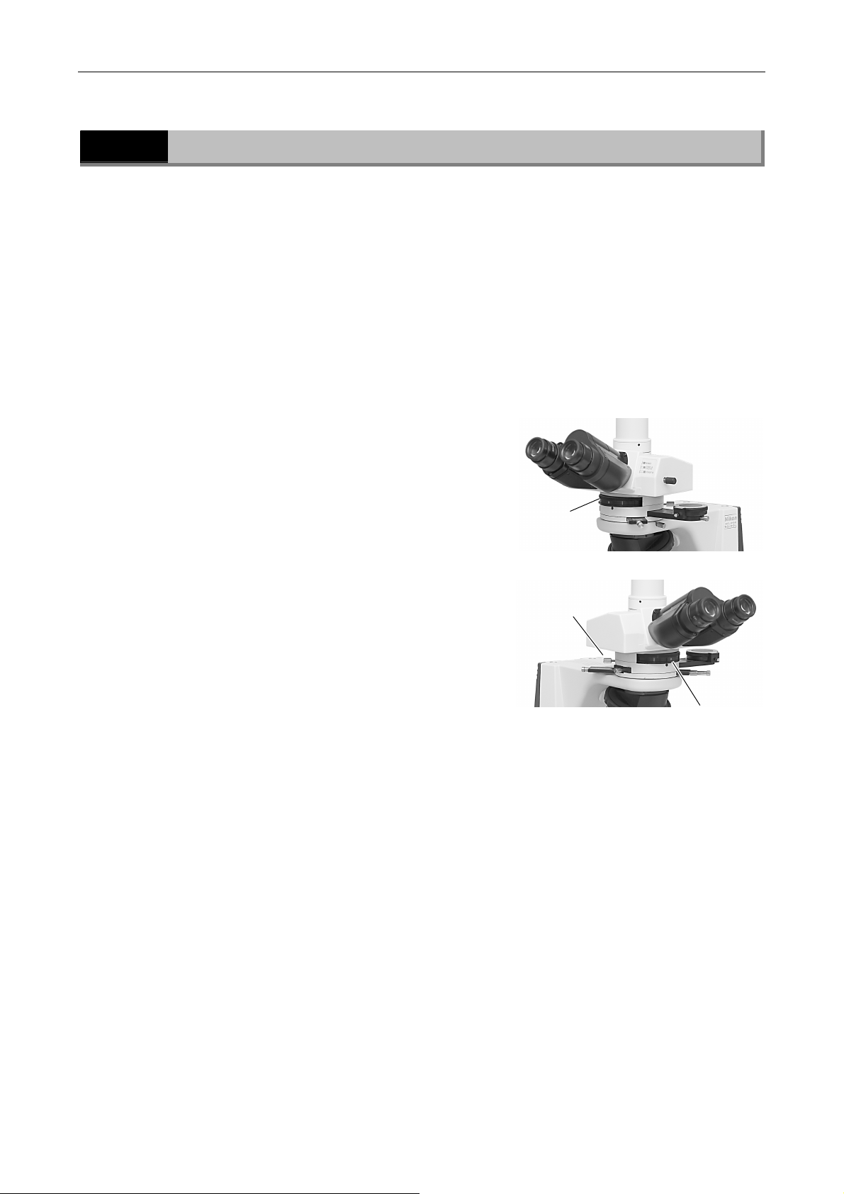
Rotate the Bertrand lens turret to
2
the “B” position to move the
Bertrand lens into the optical
path.
Focus and center the Bertrand
3
lens.
Move the
Bertrand lens
into the optical
path.
Center the Bertrand
lens using the two
screws.
⇒ P.48
Perform the conoscopic microscopy.
4
• The P-CL 1/4 λ & tint plate is not used in this microscopy. Move it to the vacant position.
• Select an objective having a large numerical aperture (high magnification: normally 40X or
higher)·
• The condenser aperture diaphragm should be adjusted so that its image circumscribes the
conoscopic view field or should be fully opened.
• The field diaphragm should be adjusted so that its image circumscribes the conoscopic view
field.
• The top lens of the swing-out condenser must be placed in the optical path.
Focus the
Bertrand lens.
21
Page 24
Chapter 2 Microscopy
2.4 Episcopic Microscopy (with the Epi Illuminator Option)
2.4
Episcopic Microscopy (with the Epi Illuminator
Option)
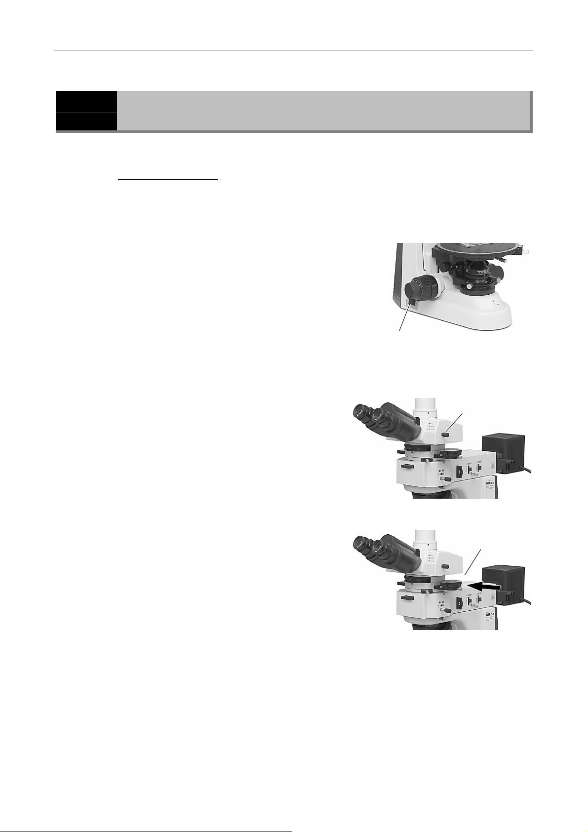
You can perform the episcopic microscopy with the epi illuminator option.
Before the microscopy
• If the cumulative lit-on time has exceeded the average operation life for lamps
of its kind, replace the lamp.
Turn off the power switch of the
1
microscope.
⇒ P.29
• If the power of the microscope is supplied, the
diascopic illumination will be lit. If you wish to
use the epi-illumination and the diascopic
illumination simultaneously, see “2.1 Diascopic
Bright-field Microscopy” to adjust the diascopic
illumination.
Set the optical path to make
2
100% light go into the binocular
eyepiece when using the
trinocular eyepiece tube.
Push the power
switch to the “O”
position.
Set the optical
path to make
100% light go
into the binocular
part
Push in the analyzer slider on the
3
polarizing intermediate tube to
Remove the
analyzer from the
optical path.
remove the analyzer from the
optical path.
22
Page 25
Chapter 2 Microscopy
2.4 Episcopic Microscopy (with the Epi Illuminator Option)
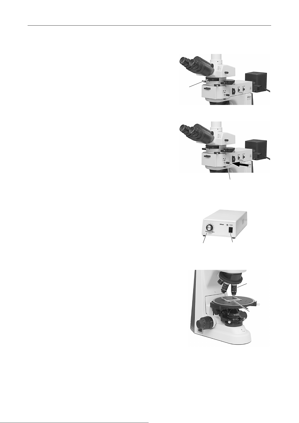
Move the Bertrand lens turret to
4
the “O” position to remove the
Bertrand lens from the optical
path.
Remove the
Bertrand lens from
the optical path.
Push in the illumination selection
5
lever on the epi illuminator to set
the bright-field position for it.
Turn on the lamp power supply for
6
Push in the
illumination
selection lever (BF).
the epi illumination. Rotate the
brightness control knob to adjust
the brightness.
Adjust the
brightness.
Turn on the power
supply.
Move the 10X objective into the
7
optical path.
Set the specimen in place with the
8
cover glass facing up.
Set the 10X
objective.
Set the specimen
with the specimen
holders
23
Page 26
Chapter 2 Microscopy
2.4 Episcopic Microscopy (with the Epi Illuminator Option)
9
10
11
12
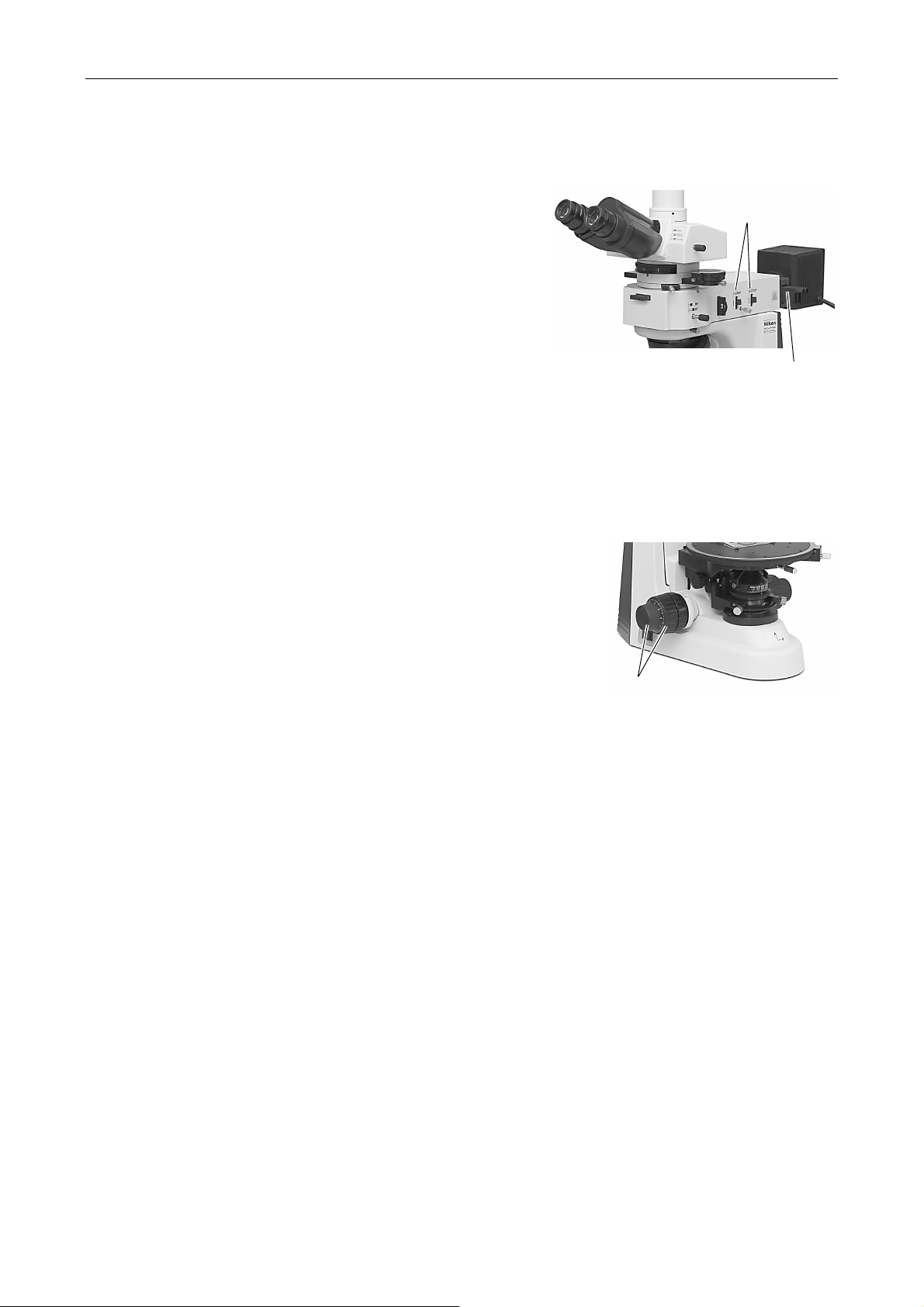
Fully open the field diaphragm and
the aperture diaphragm.
Move the open/close
lever to upper position
to fully open the field
diaphragm and the
aperture diaphragm.
Move the NCB 11 filter into the
optical path.
Move the NCB 11 filter into the
optical path. And adjust the
brightness with ND filters.
Adjust the brightness with the ND
filters.
Focus on the specimen.
Fully loosen the coarse focus
stopper ring.
⇒ P.34
Focus on the specimen
using the coarse focus knob
and the fine focus knob.
24
Page 27
Chapter 2 Microscopy
2.4 Episcopic Microscopy (with the Epi Illuminator Option)
13
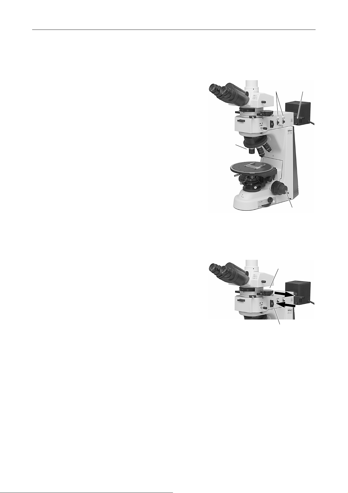
Switch to any desired objective
and view the specimen.
• Each time you change objectives, the field
diaphragm and the condenser aperture
diaphragm must be adjusted.
For the bright-field microscopy, the field aperture
should be adjusted so that its image
circumscribes the view field. And the aperture
diaphragm should be 70% to 80% of the
numerical aperture of the objective.
⇒ P.51
⇒ P.52
• Focus on the specimen again using the fine focus
knob or the coarse focus knob.
⇒ P.53
• Use the ND filters on the epi illuminator to adjust
the brightness.
• To use an oil immersion type objective or a water
immersion type objective, perform the oil
immersion or water immersion.
Switch to
any desired
objective.
Focus on the
specimen
using the
coarse focus
knob and the
fine focus
knob.
Adjust the field diaphragm
and the aperture diaphragm.
Adjust the
brightness
with the
ND filters.
14
15
To perform the episcopic
polarization microscopy, insert the
polarizer slider into the place on
Move the analyzer into
the optical path.
the side of the illuminator and
place the analyzer on the
intermediate tube into the optical
path.
• The polarizer azimuth should be adjusted with
the ring on the polarizer slider. For the
adjustment method, see P.45.
• To perform the conoscopic microscopy, move the
Bertrand lens into the optical path. (See “2.3
Conoscopic Observation.”)
Move the polarizer into
the optical path.
To return to the bright-field microscopy
• Turn off the power supply for the lamp.
• Pull the illumination selection lever on the epi illuminator to set the dark-field position for it.
• Turn on the power switch of the microscope to light the diascopic illumination.
• Remove the analyzer and the Bertrand lens from the optical path.
16
Turn off all the power after completing the observation.
25
Page 28
Chapter 2 Microscopy
2.5 Photomicroscopy
2.5
1
2
Photomicroscopy
For detailed discussions of the camera, photomicroscopic software, and PC, refer to the
operating manuals provided with the respective products. The following instructions assume a
DS camera head DS-5M and DS-L1 camera control unit.
Adjust the microscope for proper image observation.
See the directions given in sections from “2.1 Diascopic Bright-field Microscopy” to “2.4
Episcopic Microscopy.”
Adjust the camera head attaching position until the image is
displayed properly.
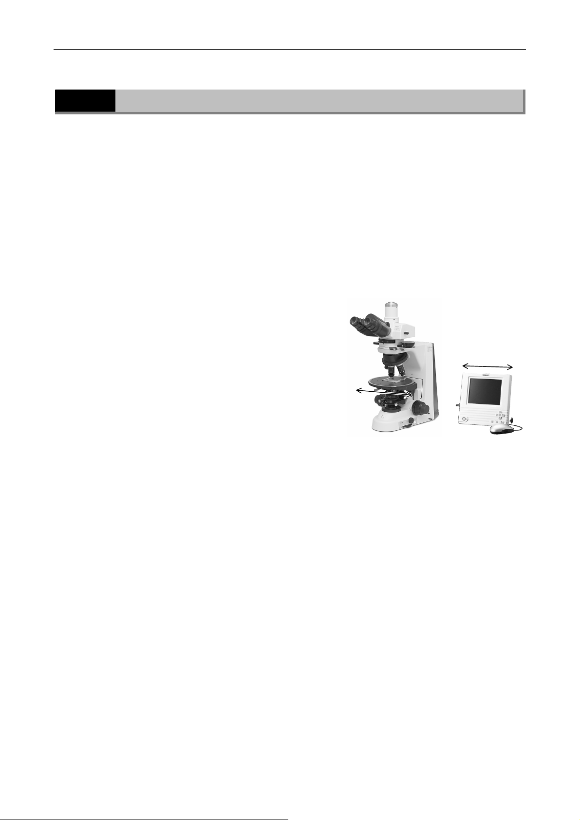
Loosen the attachment guide fixing screw on the C
mount and adjust the camera position so that
moving the stage left-right moves the image on the
monitor in the opposite direction. After making the
appropriate adjustments, tighten the screws firmly.
(B)
(A)
Adjust the directions (A) and (B).
Make camera settings.
3
For detailed information, refer to the operating manual provided with the camera.
When using the DS-L1, you must choose and enter at least the following information:
• Folder for data storage
• Name of file to be saved (You can select “Auto.”)
• File format and file size
• Date and destination of data
Select the camera scene mode suitable for the microscopy
4
method.
Set the camera white balance.
5
To adjust the white balance, press the WB button while capturing an image of a clear section of
a specimen slide. For fluorescent photomicrography, adjust the white balance under normal
lighting conditions before the image capturing.
26
Page 29

Chapter 2 Microscopy
2.5 Photomicroscopy
Capture and save images.
6
Position the specimen.
Readjust the focus.
Adjust the image brightness using the camera exposure compensation function.
Check the image using the Freeze button.
When the image is acceptable, press the CAPT. button to save the image.
The operating procedure differs if DF/FL scene mode is selected. For details, see the manual for
the camera.
27
Page 30

3
Item Title Operating sections
3.1 Power ON/OFF Power switch
3.2 Brightness adjustment Brightness control knob, preset switch, ND filter, and color
Individual Operations
compensating filter
3.3 Optical path selection (for trinocular
eyepiece tube)
3.4 Stage vertical movement Coarse/fine focus knobs, coarse focus torque adjustment
3.5 Stage rotation Circular graduated stage, vernier, and stage rotation clamp
3.6 Diopter adjustment Diopter adjustment rings
3.7 Interpupillary distance adjustment Eyepiece sleeve
3.8 Adjusting the condenser position Condenser focus knob, condenser centering screws
3.9 Adjusting the aperture diaphragm Condenser aperture diaphragm, objective
3.10 Selecting a condenser Condenser
3.11 Adjusting the field diaphragm Field diaphragm control
3.12 Setting a filter on the field lens NCB filter, ND 16 filter, GIF filter
3.13 Centering the objective Centering nosepiece, objective
3.14 Oil immersion operation Oil immersion type objective, oil immersion type condenser
3.15 Water immersion operation Water immersion type objective, water immersion type
3.16 Polarization microscopy Polarizer for diascopic microscopy, polarizer for episcopic
Optical path selection lever
knob, and coarse focus stopper ring
screw
condenser
microscopy, polarizing intermediate tube (analyzer, Bertrand
lens), P-CL 1/4 λ & tint plate, P-CS Senarmont compensator,
P-CQ quartz wedge
3.17 Episcopic microscopy Epi illuminator
3.18 Image capturing Camera
28
Page 31
Chapter 3 Individual Operations
3.1 Power ON/OFF
3.1
3.1.1
3.1.2
Power ON/OFF
Power Supply for the Microscope
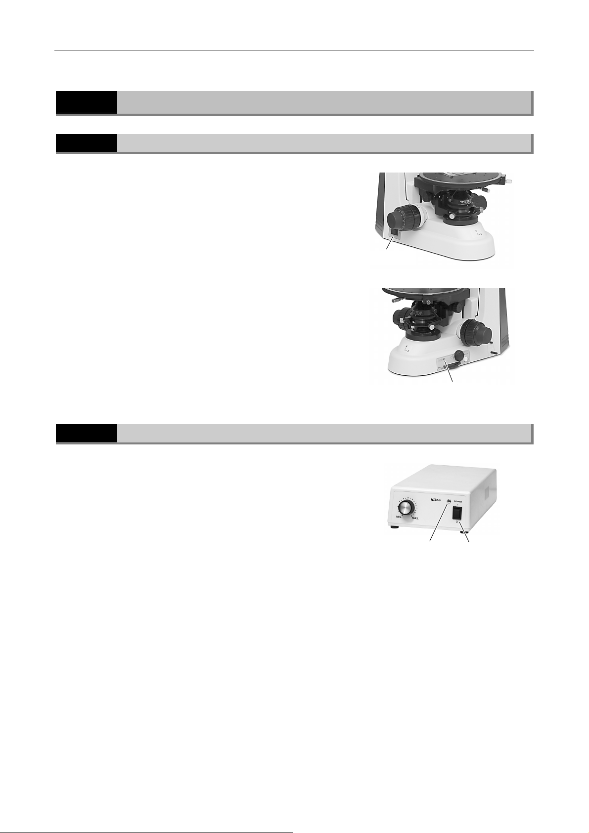
To turn on the microscope, press the power switch
to the “I” position.
To turn off the microscope, press the power switch
to the “O” position.
When the power to the microscope is on, the power
indicator on the right side of the microscope is lit.
Power Supply for the Epi Illuminator
To turn on the power supply, press the power
switch to the “I” position. The lamp will be lit.
To turn off the power supply, press the power
switch to the “O” position. The lamp will be turned
off.
When the power to the power supply is on, the
power indicator on the front of the power supply is
lit.
Power switch
Power indicator
Power indicator
Power switch
29
Page 32
Chapter 3 Individual Operations
3.2 Brightness Adjustment
3.2
Brightness Adjustment
The brightnesses of images are adjusted with the following methods:
Method Operating controls Section
Diascopic image
color temperature shifts)
Setting ND filters (free from color
temperature shifts)
Episcopic image
(Monitor image) Camera adjustment Application software for camera
3.2.1
Adjusting the Brightness Control Knob
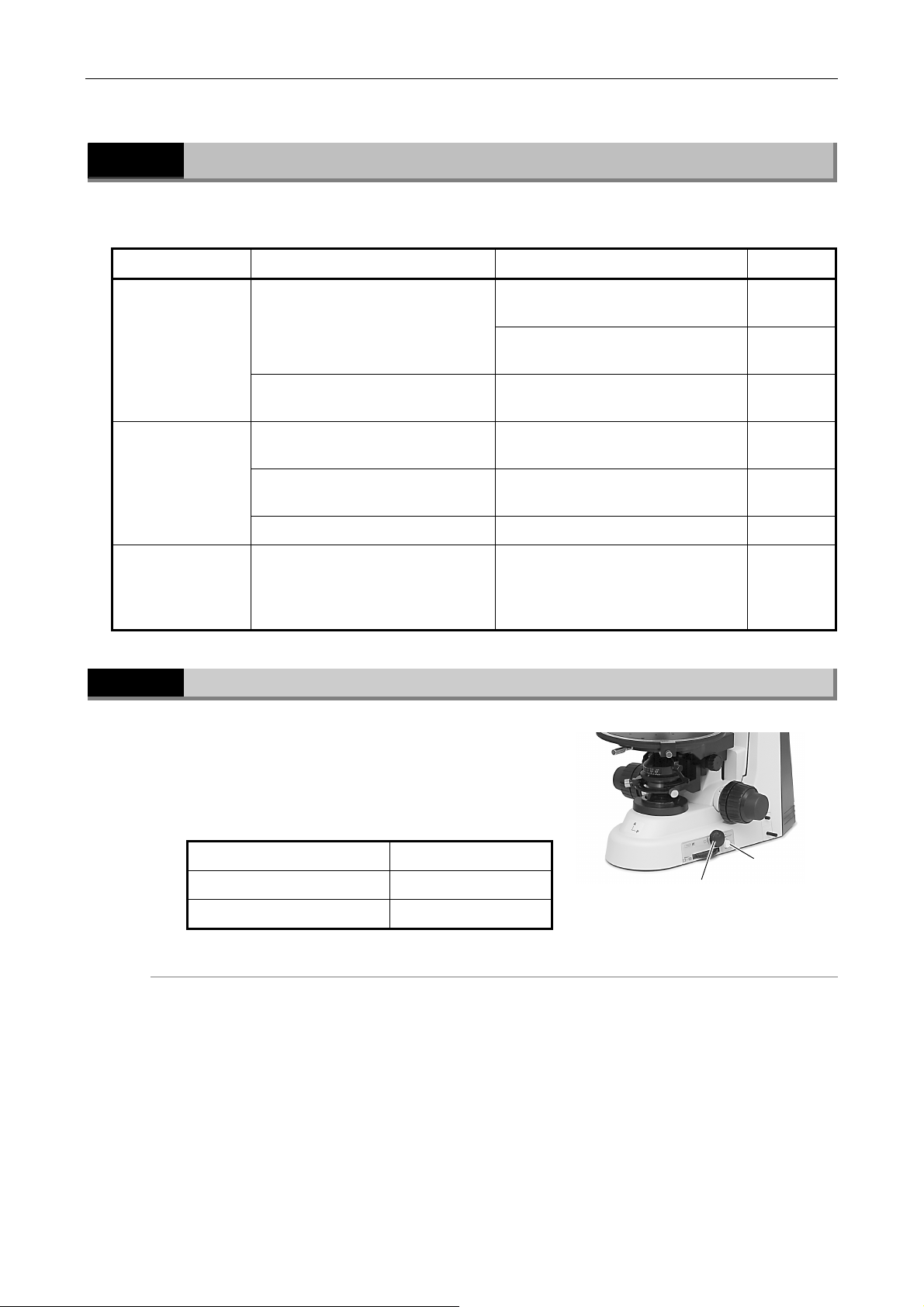
With the preset switch in the out position, rotate
the brightness control knob. (The brightness
control knob is disabled if the preset switch is
depressed.)
Adjusting the lamp voltage (causes
color temperature shifts)
Setting ND filters (free from color
temperature shifts)
Extincting episcopic images Power switch for the microscope 3.2.6
Brightness control knob (microscope
body)
Preset switch, preset brightness
volume-control
ND filter IN/OUT lever 3.2.3
Brightness control knob on the power
supply for the illuminator
Filter slider on the epi illuminator 3.2.5
control: display mode, exposure
mode, exposure compensation,
camera gain adjustment, and so on.
3.2.1 Adjusting the lamp voltage (causes
3.2.2
3.2.4
3.2.7
Brightness control knob Image brightness
Clockwise rotation Becomes brighter.
Counterclockwise rotation Becomes darker.
Brightness
control knob
The preset switch
must not be
depressed.
Color temperature shift
Adjusting brightness with the brightness control knob will affect the lamp color temperature and
alter the color balance of the image. When accurate color reproduction is critical, set the
brightness control knob to a midpoint setting and use the ND filters to make brightness
adjustments.
30
Page 33
Chapter 3 Individual Operations
3.2 Brightness Adjustment
3.2.2
How to use the preset brightness volume-control
3.2.3
Adjustment Using the Preset Switch
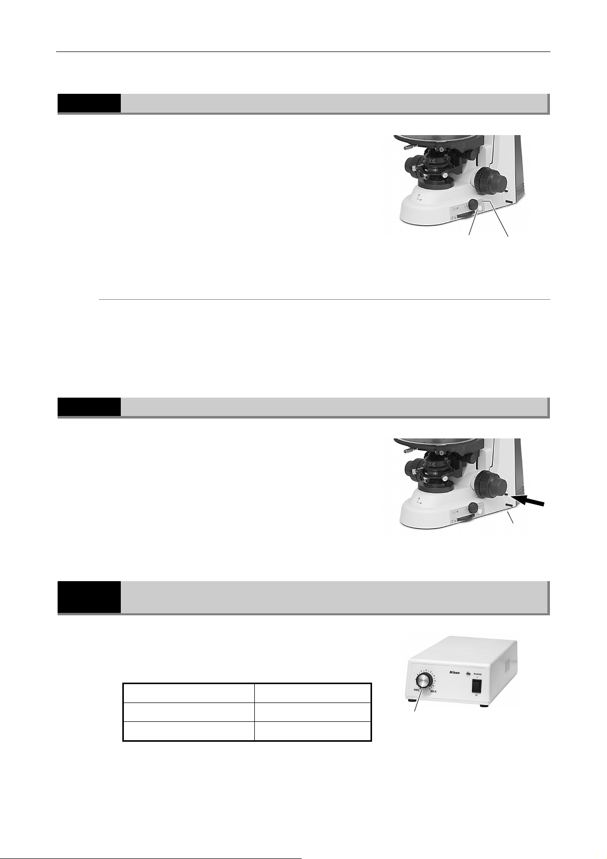
Push in the preset switch to enable the brightness
level (lamp voltage) previously set with the preset
brightness volume-control.
Toggle the preset switch – that is to say, return it
to the out position – to enable the brightness
control knob setting.
Preset switch
Push in the preset switch to set it to the depressed position.
While viewing the actual image, turn the volume-control with a precision screwdriver until the
desired brightness is achieved.
Setting the preset switch to the depressed position enables the brightness level set with the
preset brightness volume-control .
Preset brightness
volume-control
Adjustment Using the ND Filter IN/OUT Lever
Pushing in the upper lever moves the ND filter
(light intensity adjustment filter) into the optical
path and reduces brightness. The color balance of
the image remains unaffected.
Upper lever : filter IN
Lower lever : filter OUT
3.2.4
Adjustment Using the Brightness Control Knob on the Power Supply for the Illuminator
To perform the episcopic microscopy with the epi
illuminator, turn on the power supply for it and adjust
the brightness control knob.
Brightness control knob Image brightness
Rotate clockwise To brighten the image
Rotate counterclockwise To darken the image
Brightness control knob
31
Page 34
Chapter 3 Individual Operations
3.2 Brightness Adjustment
3.2.5
3.2.6
3.2.7
Adjustment Using ND Filters on the Epi Illuminator
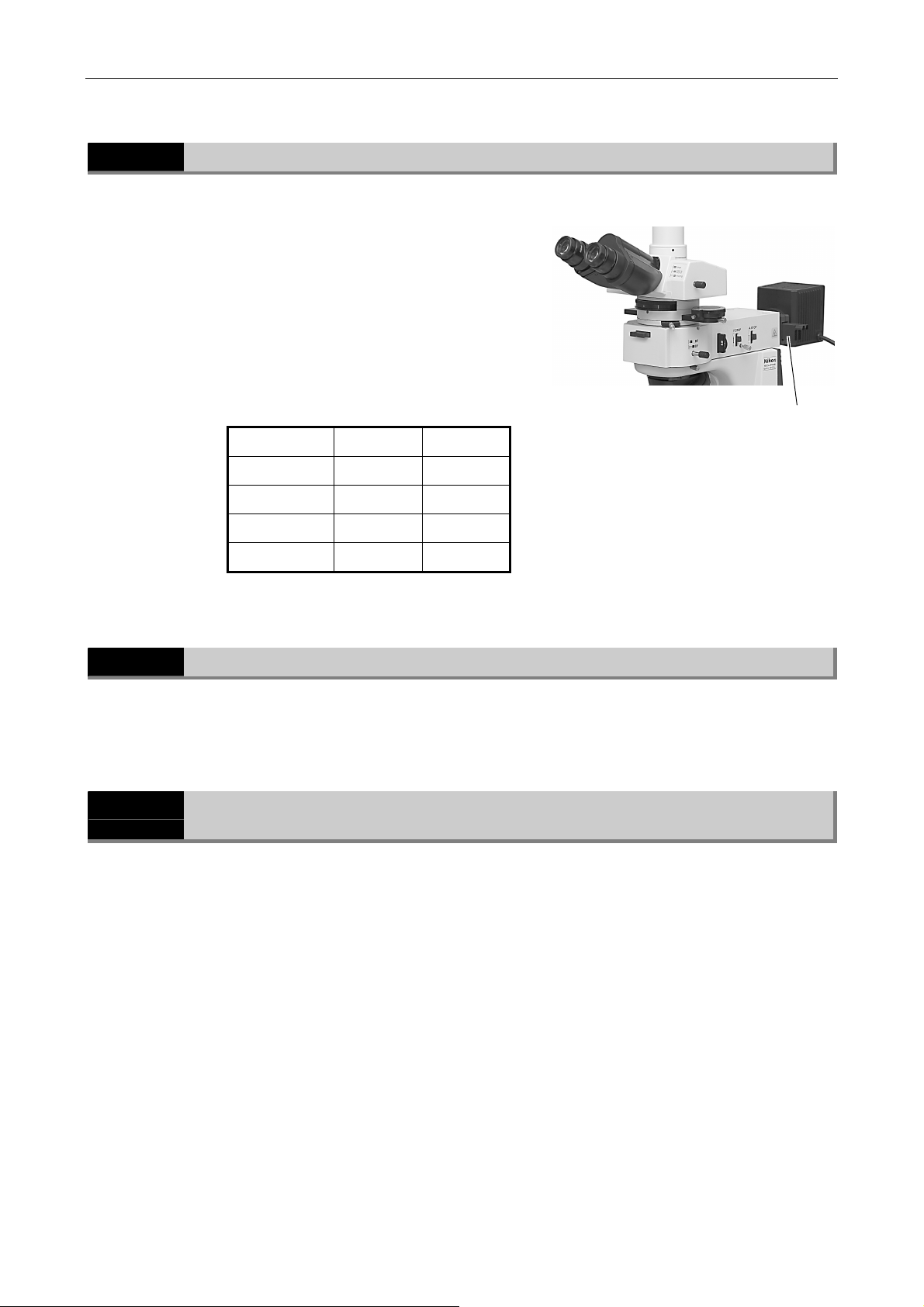
The LV-UEPI universal epi illuminator has two filter
sliders. You can use suitable ND filters by operating
the filter sliders.
ND filters are used to adjust the light intensity. A
large number filter has a low transmittance and is
used to get a dark image. ND filters do not affect
the color balance.
ND4 and ND16 filters are provided. You can get the
following four types of brightness by using these
filters.
Brightness
1 Out Out
1/4 In Out
1/16 Out In
1/64 In In
(Out: out of the optical path, In: in the optical path
ND4 ND16
)
Filter sliders
Transmitted Image in the Episcopic Microscopy
To perform the episcopic microscopy with the epi illuminator, turn off the power switch of the
microscope to extinct the transmitted image in normal times.
Camera Adjustment (Adjusting the Brightness of the Image on the Monitor)
When observing images captured by the camera and displayed on the monitor, you can adjust
brightness by varying camera adjustment parameters, such as display mode, exposure mode,
metering mode, exposure compensation, and image level adjustment.
For detailed information, refer to the operating manual provided with the camera or camera
control software.
32
Page 35
Chapter 3 Individual Operations
T
3.3 Optical Path Selection (for Trinocular Eyepiece Tube)
3.3
3.3.1
3.3.2
3.3.3
Optical Path Selection (for Trinocular Eyepiece Tube)
Light Distribution
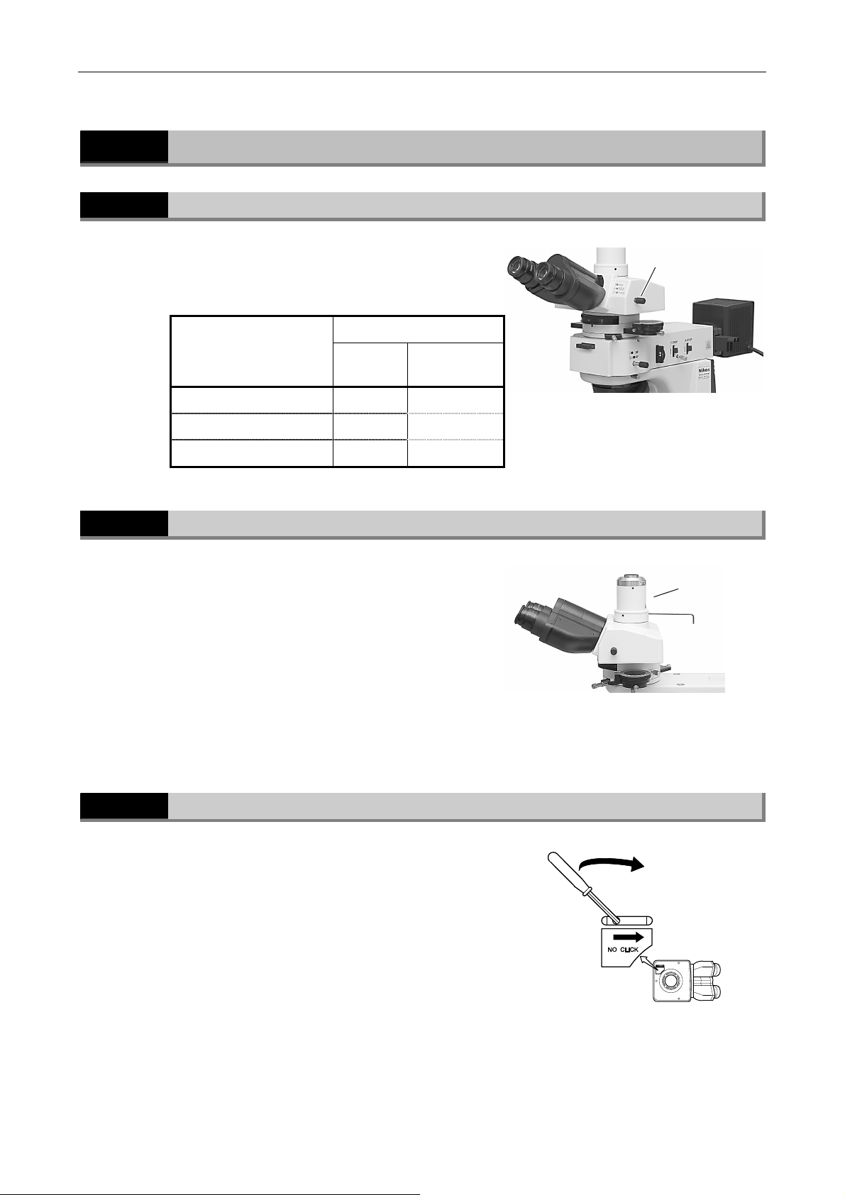
With the trinocular eyepiece tube, the optical path
selection lever allows the light distribution to the
binocular section and vertical tube section.
Optical path
selection lever
position
Pushed in 100 0
Pulled out one notch 20 80
Pulled out two notches 0 100
Light distribution (%)
Binocular
section
Vertical tube
section
Vertical Tube Adapter
The TV vertical tube adapter or the TV vertical tube
adapter 0.55X can be mounted on the vertical tube
section of the trinocular eyepiece tube. To mount
the adapter, remove the cap from the vertical tube
section of the trinocular eyepiece tube, insert the
vertical tube adapter, and fix it with three screws
on the vertical tube section with the attached tool.
his picture shows the TV vertical tube
adapter and C mount adapter.
Disabling the Clicking of the Optical Path Selection Lever
The trinocular eyepiece tube has a “NO CLICK”
switch on the tube attaching surface. Slide this
switch in the direction of the arrow with the tip of a
pointed tool to disable clicking for the optical path
switching lever. Set the switch to this position if
you need to eliminate the slight vibrations resulting
from the clicking action.
Optical path
selection lever
TV vertical tube
adapter
33
Page 36
Chapter 3 Individual Operations
3.4 Stage Vertical Movement (Focusing)
3.4
3.4.1
3.4.2
Stage Vertical Movement (Focusing)
Prohibited Actions
Avoid the following actions, which can cause equipment malfunctions. Never do them at all.
• Rotating the right and left coarse/fine focus knobs in opposite directions.
• Rotating the coarse focus knob past the stopper.
Knob Rotation and Stage Movement
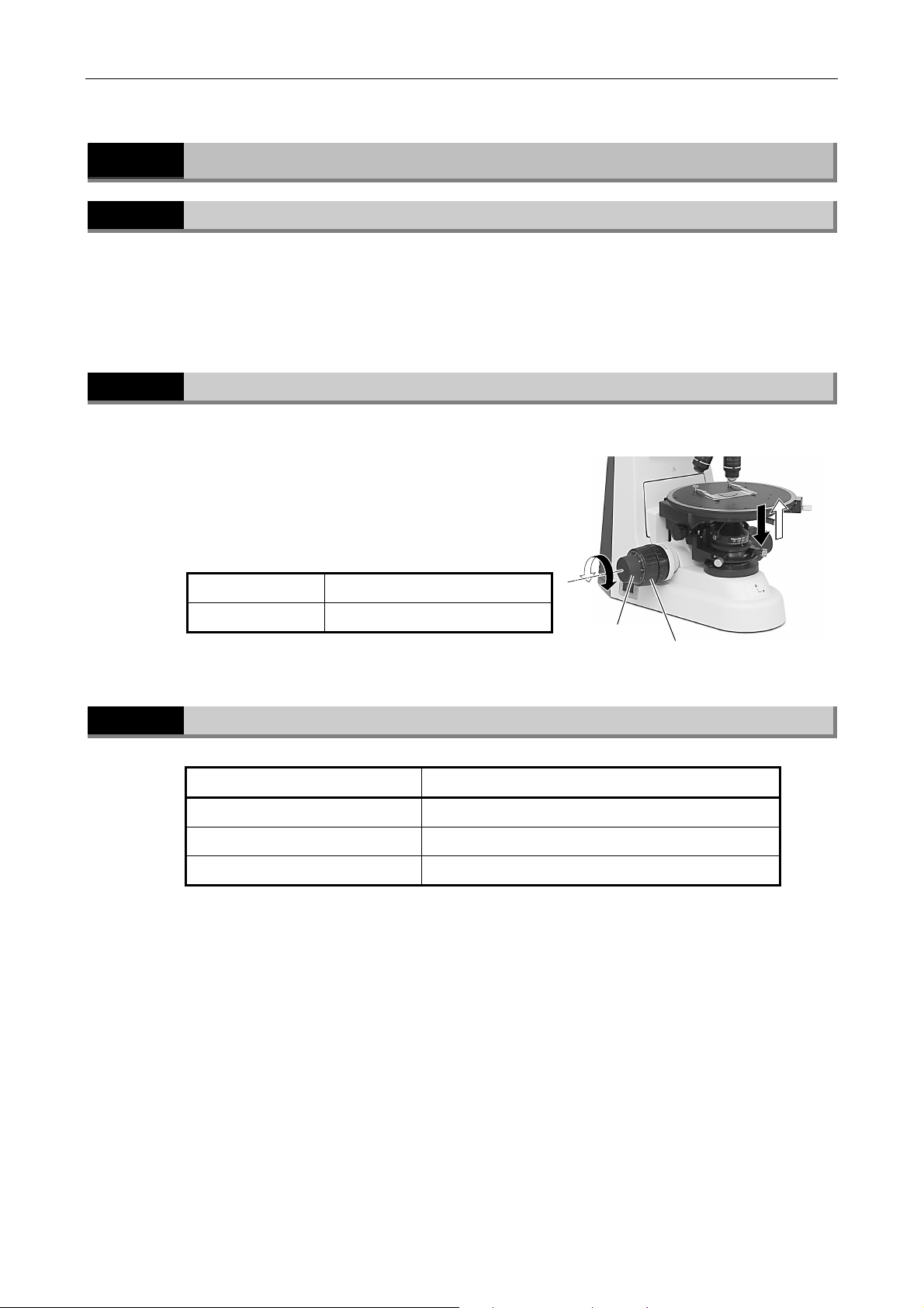
To move the stage up/down, rotate the coarse
focus knob or the fine focus knob located on both
sides of the microscope.
You can move the stage up/down to focus on the
specimen by rotating these knobs.
To lower the stage Turn the knob toward the front.
To raise the stage Turn the knob toward the back.
3.4.3
Number of Knob Turns and Distance of Stage Travel
Number of knob turns Distance of stage travel (vertical direction)
Coarse focus knob 1 turn Approx. 13.8 mm
Fine focus knob 1 turn Approx. 0.1 mm
Fine focus knob 1 notch
The vertical motion range (coarse/fine focus stroke) of the stage is from 2 mm above the focal
point (reference position) to approximately 28 mm below the focal point.
1 µm
Fine focus knob
Coarse focus knob
34
Page 37
Chapter 3 Individual Operations
3.4 Stage Vertical Movement (Focusing)
3.4.4
3.4.5
Adjusting the Rotating Torque of the Coarse Focus Knob
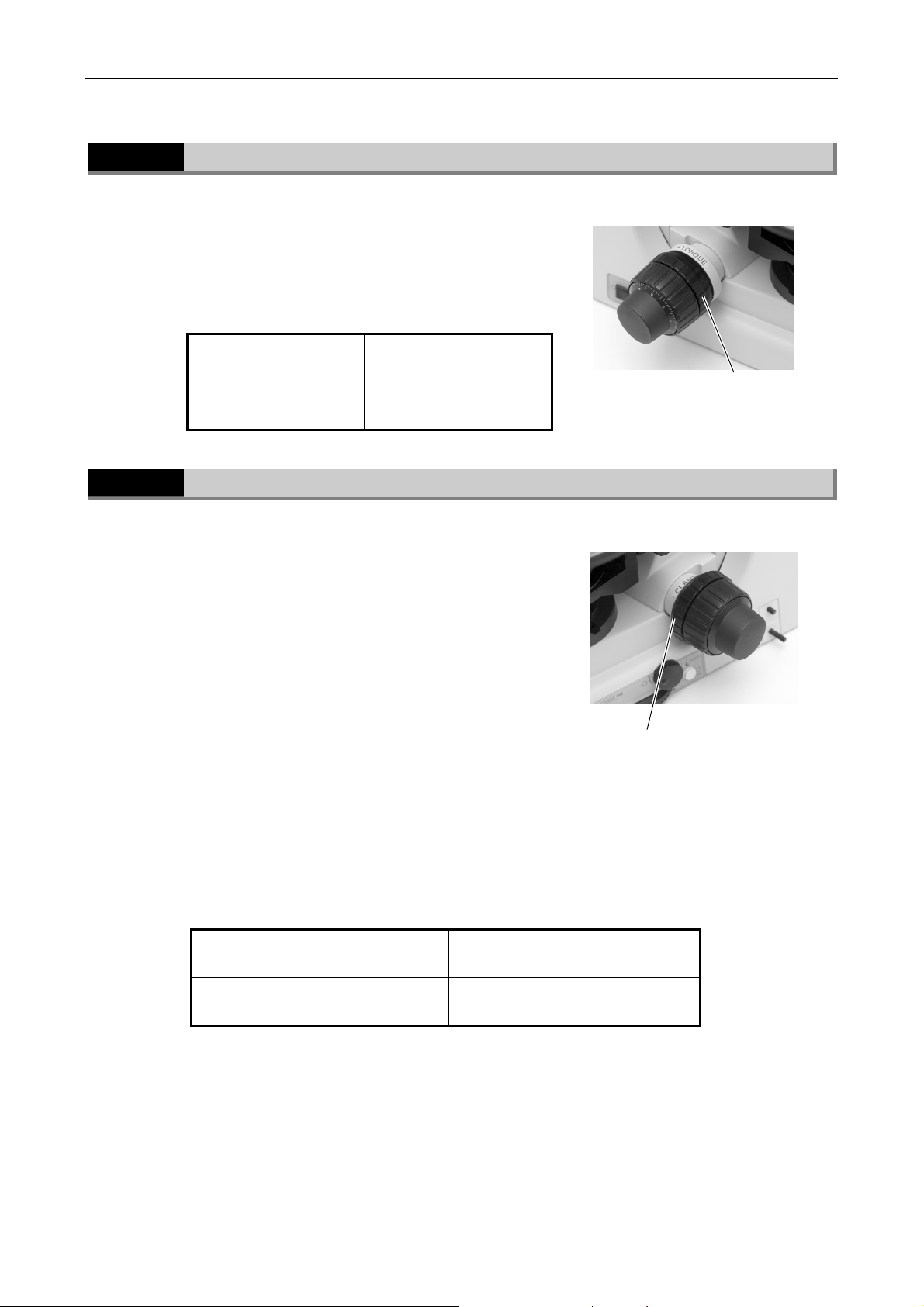
Adjust the rotation torque of the coarse focus ring
(rotation resistance) by turning the torque
adjustment ring (TORQUE) located at the base of
the coarse focus knob. If the torque is too low, the
stage may descend with its own weight.
Rotate the ring in the
direction of arrow
Rotate the ring in the
direction opposite to arrow
To make the knob harder to
turn
To make the knob easier to
turn
Coarse focus torque
adjustment ring
Coarse Focus Stopper Ring
When the coarse focus stopper ring is rotated in
the direction of the arrow (labeled “CLAMP→”), the
coarse focus knob cannot be used to move the
stage any higher.
(Movement of the stage by the fine focus knob is
not restricted.)
If you must change specimens and move the stage
up/down repeatedly, it will save your time for
focusing that the coarse focus stopper ring is fixed
at the focus point.
Example usage
With the sample in focus, turn the coarse focus
stopper ring as far as it goes in the direction of the
arrow (labeled “CLAMP→”). When changing the
sample, lower the stage by turning only the coarse
focus knob. After changing the sample, gently raise
the stage by turning only the coarse focus knob as
far as it goes. The sample should be roughly in
focus.
Rotate the ring in the direction of
arrow as far as it goes
Rotate the ring in the direction
opposite to arrow as far as it goes
To restrict the movement of the
coarse focus knob
To release the restriction
Coarse focus
stopper ring
35
Page 38
Chapter 3 Individual Operations
3.5 Stage Rotation
3.5
3.5.1
3.5.2
Stage Rotation
Stage Rotation
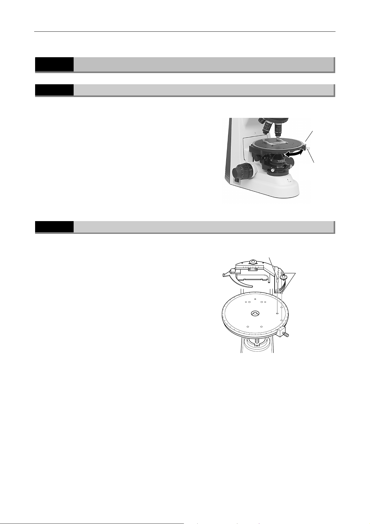
To rotate the circular graduated stage, loosen the
stage rotation clamp screw and turn the whole
stage carefully by hand.
The angle of rotation can be read to 0.1 degrees
with the two vernier scales.
Attachable Mechanical Stage (Option)
The optional attachable mechanical stage is
installed by inserting the two pins on the bottom
into the two pinholes on the stage surface. Tighten
the clamp screw using the supplied hexagonal
wrench.
Vernier
Stage rotation
clamp screw
Clamp screw
Positioning pins
To move the specimen position under observation,
rotate the knob on the stage. You can adjust the
position in the X-direction and Y-direction
individually. (Travel range: 35 x 25 mm) The travel
amount can be read to 0.1 mm with the two
vernier scales.
Specimens are fixed with a lever. So you can
change specimens with easy operation.
36
Page 39
Chapter 3 Individual Operations
3.6 Diopter Adjustment
3.6
Diopter Adjustment
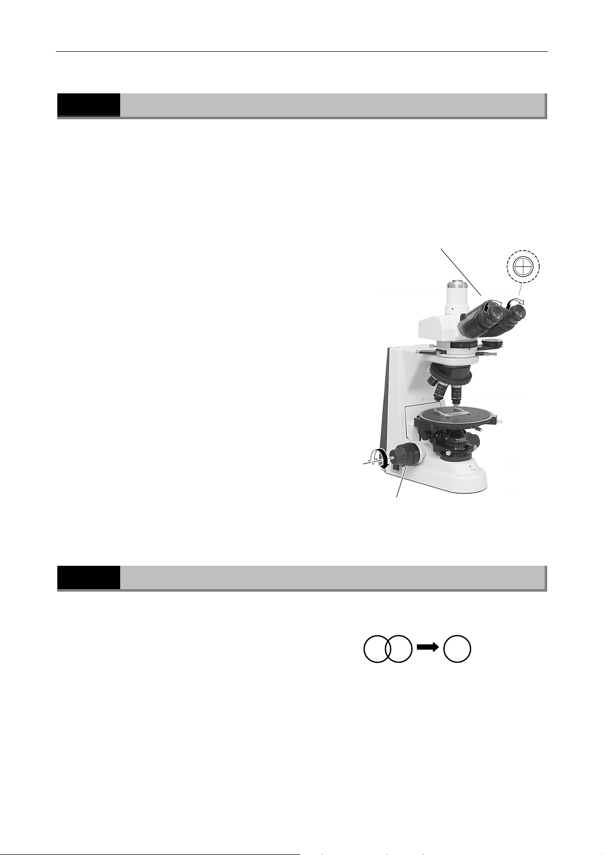
Diopter adjustment compensates for differences in visual acuity between the right and left eyes,
improving binocular observation. It also minimizes focal deviations when switching objectives.
In the case of a polarizing microscope, since an eyepiece containing crosshairs is used for the
right eye, the procedure for adjusting the diopter differs from that of an ordinary microscope.
(1) Observe the right eyepiece with the right eye.
Turn the diopter adjustment ring to bring the
crosshair in the eyepiece into focus.
(2) Still observe the right eyepiece with the right
eye. Turn the fine/coarse focus adjustment
knob to bring the specimen on the stage into
focus.
(3) Observe the left eyepiece with the left eye.
Turn the diopter adjustment ring on the
eyepiece to bring the specimen into focus.
(not the fine/coarse focus adjustment knob)
(3) Focus on the
specimen with
the left eye.
(1) Focus on the
crosshair with the
right eye.
(2) Focus on the specimen with the
right eye.
3.7
Interpupillary Distance Adjustment
Interpupillary adjustment improves the ease of
binocular observation.
Perform steps 1 to 12 in “2.1 Diascopic Bright-Field
Microscopy” and focus on the specimen using the
10x objective. Then, move the eyepiece sleeve until
the view fields for the right and left eyes coincide.
View field
Converge until
the right and left
view fields
coincide.
37
Page 40
Chapter 3 Individual Operations
3.8 Adjusting the Condenser Position
3.8
Adjusting the Condenser Position
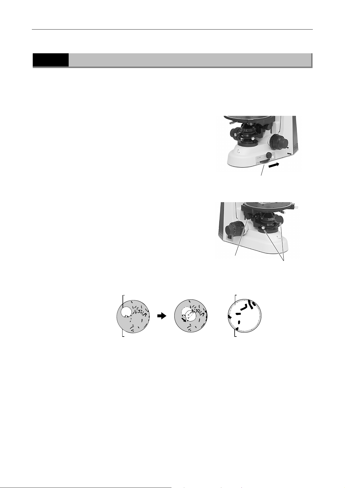
Adjust the condenser position (focusing and centering) so that the light passing through the
condenser forms an image at the correct location (center of the optical path) on the specimen
surface.
(1) Perform steps in “2.1 Diascopic Bright-Field
Microscopy” and focus on the specimen using
the 10x objective.
(2) Stop down the field diaphragm to the
minimum setting.
(3) Turn the condenser focus knob to form the
field diaphragm image on the specimen
surface.
(4) Turn the condenser centering screws so that
the field diaphragm image is positioned in the
center of the view field.
(5) Move the 40X objective into the optical path.
Turn the coarse/fine focus knobs and focus on
the specimen.
(6) Turn the condenser focus knob to form the
field diaphragm image on the specimen
surface.
Move the field diaphragm control to
stop down the field diaphragm to
its minimum setting.
(7) Turn the condenser centering screws so that
the field diaphragm image is positioned in the
center of the view field. This is easiest if you
set the field diaphragm aperture to slightly
smaller than the eyepiece view field.
Condenser
focus knob
Condenser
centering screw
Field diaphragm image Field diaphragm image
Eyepiece viewfield
Eyepiece viewfield
38
Page 41
Chapter 3 Individual Operations
3.9 Adjusting the Aperture Diaphragm
3.9
3.9.1
Adjusting the Aperture Diaphragm
The aperture diaphragm for the diascopic microscopy is adjusted with the condenser aperture
diaphragm knob.
For the diaphragms of the epi illuminator, refer to “3.17 Episcopic microscopy.”
For the Bright-field Microscopy and the Orthoscopic Microscopy
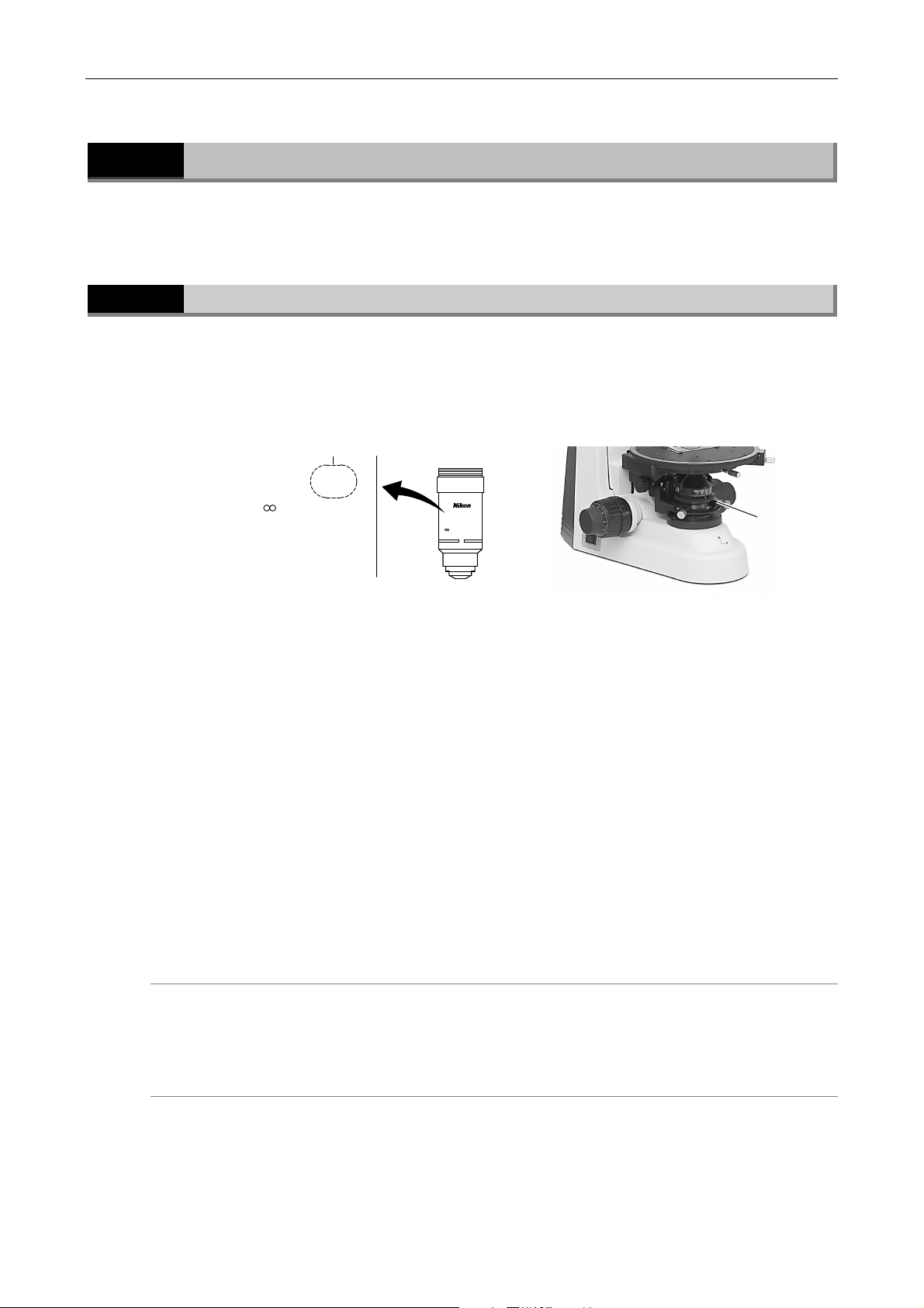
The numerical aperture for the condenser can be read with the scale on it. You can adjust the
numerical aperture with the scale. For the bright-field microscopy and the orthoscopic
microscopy, set the index of the aperture diaphragm to the point between 70% and 80% of the
numerical aperture of the objective in normal cases. The numerical aperture of the objective is
labeled on its side.
Numerical aperture
40
X/ 0.65
/0.17 WD 0.65
0.65 x 0.7 ~ 0.8 = 0.455 ~ 0.52
Objective
P
40
X/0.65
/0.17 WD 0.65
40x
P
Condenser
aperture
diaphragm
knob
The aperture diaphragm is important because it is related to the resolution, contrast, depth of
focus and brightness of the optical image. Turning the condenser aperture diaphragm ring
changes the size of the aperture diaphragm.
As the aperture diaphragm is stopped down, resolution and brightness are reduced while
contrast and depth of focus are increased. Conversely, as the aperture diaphragm is opened,
resolution and brightness are increased while contrast and depth of focus are reduced. It is not
possible to adjust one pair of characteristics without affecting the other. Generally, a satisfactory
image with appropriate contrast can be obtained with an aperture setting that is 70% to 80% of
the numerical aperture of the objective. The numerical aperture is indicated on the barrel of each
objective.
An indication of 40×/0.65 means that the magnification is 40× and the numerical
aperture is 0.65.
If the aperture diaphragm is stopped down too far, the resolution is reduced; therefore, except
when viewing a nearly transparent specimen, we do not recommend stopping down the aperture
to less than 60% of the numerical aperture of the objective.
Adjusting the size of the aperture diaphragm according to the condenser scale
Since the condenser scale indicates the numerical aperture, adjust the aperture diaphragm ring
according to the scale. (Normally, the index on the aperture diaphragm ring should be aligned
with the scale line corresponding to 70% to 80% of the numerical aperture of the objective.)
Adjusting the size of the aperture diaphragm using the Bertrand lens
Insert the Bertrand lens into the optical path (by placing in position “B”). Turn the diaphragm
control ring to stop down the aperture diaphragm to its minimum setting. Turn the Bertrand lens
focus ring to focus on the aperture diaphragm image. Turn the diaphragm control ring to adjust
the aperture diaphragm. (This is normally adjusted to 70-80% of the view field.)
39
Page 42
Chapter 3 Individual Operations
T
3.10 Selecting a Condenser
3.9.2
3.10
For Conoscopic Microscopy
For the conoscopic microscopy, the condenser aperture diaphragm functions as a field diaphragm
on the conoscopic image surface. Stop down the diaphragm until it circumscribes the
circumference of the view field of the conoscopic image (pupil of the objective).
Selecting a Condenser
To perform the polarization microscopy, the P swing-out condenser must be used.
Objective
magnification
1x
2x
4x
10x to 100x
Depending on the type of objective, the indicated numerical aperture of the objective may not be
achieved.
P swing-out condenser
(✓: suitable, -: not suitable)
-
Note 1
✓
✓
Note 1: Swing out the top lens before use.
For example, when an objective with an N.A. of 1.4 is used, the maximum aperture of the P
swing-out condenser will be only about 65% of the objective's N.A., even when the condenser
aperture diaphragm is fully open.
How to use the P swing-out condenser
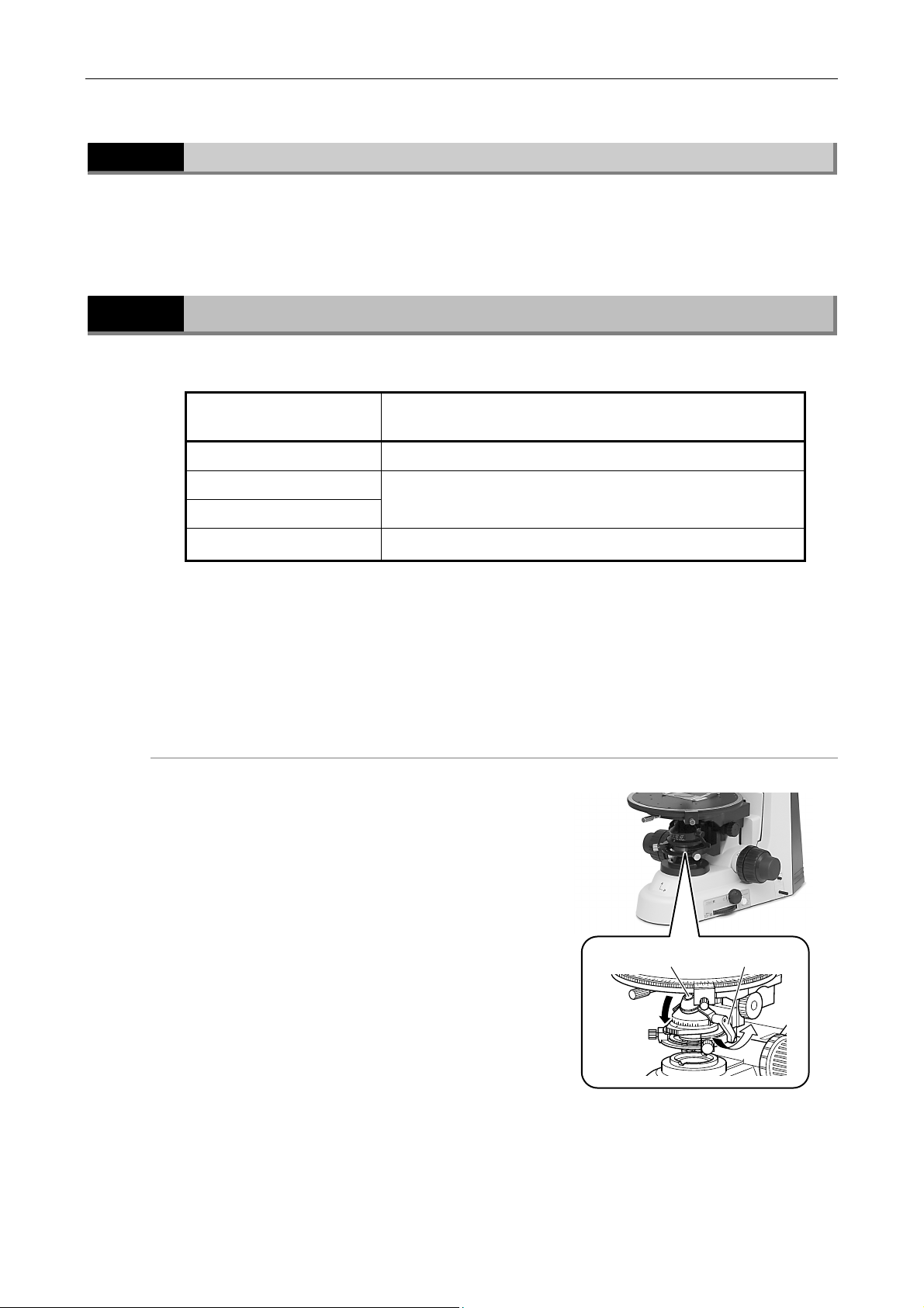
The top lens of the P swing-out condenser can be
moved outside the optical path with the swing-out
knob.
During normal bright-field microscopy or
orthoscopic microscopy using a low-power objective
of 4× or lower, swing out the top lens.
During microscopies using an objective of 10X or
higher or conoscopic microscopy, the top lens is
placed into the optical path.
During measurement of retardation or evaluation
by interference color, swing out the top lens (the
condenser aperture diaphragm may be stopped
down) and illuminate with light that is as parallel to
the optical axis as possible.
op lens
Swing-out knob
40
Page 43
Chapter 3 Individual Operations
3.11 Adjusting the Field Diaphragm
3.11
Adjusting the Field Diaphragm
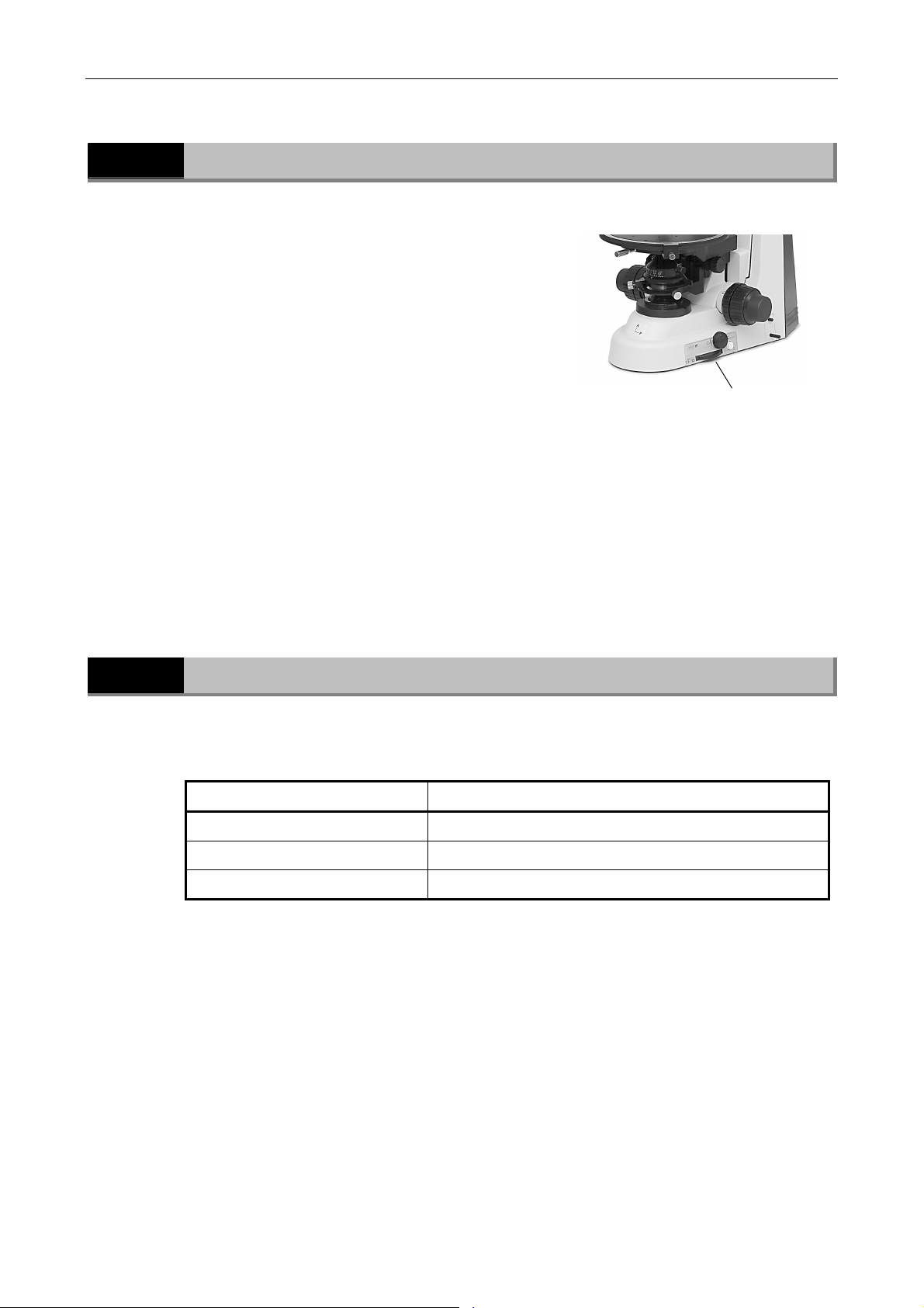
The field diaphragm restricts illumination to the
area of the specimen that is being viewed.
Operating the field diaphragm control changes the
size of the field diaphragm. For normal observation,
the size of the diaphragm should be such that it is
just outside the edge of the viewfield.
If a broader area than necessary is illuminated,
stray light will enter the optical system, creating
flaring, reducing the contrast of the optical image,
and expanding the area of color fading of the
specimen. Appropriate field diaphragm settings are
particularly important for photomicrography and
digital image capturing.
In general, good results will be obtained by
stopping down the field diaphragm to settings
slightly wider than the area to be reproduced within
the photo frame or monitor display.
*
For the field diaphragm of the epi illuminator,
refer to “3.16 Episcopic microscopy.”
Field diaphragm control
3.12
Setting a Filter on the Field Lens
You can attach a filter of 45 mm diameter into the filter pocket of the field lens part (beneath the
condenser). (option)
Filter Application
NCB 11 (color balancing filter) For color balance adjustment and color photomicrography
ND 16 (transmittance: 6%) For brightness adjustment
GIF For retardation measurement and contrast adjustment
41
Page 44
Chapter 3 Individual Operations
T
3.13 Centering the Objective
3.13
Centering the Objective
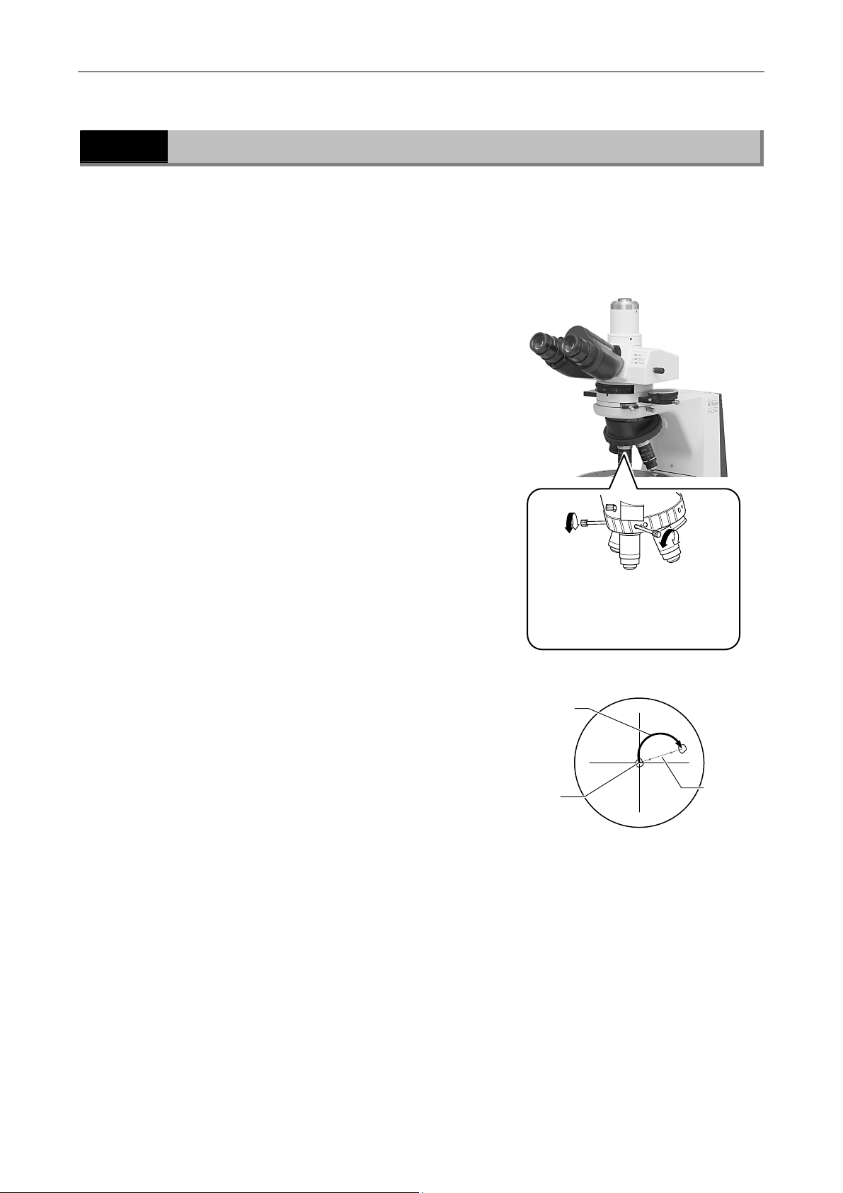
To perform the polarization microscopy, the center of the objective optical path must be aligned
to the rotation center of the circular graduated stage. This product comes with the centering
nosepiece. You can perform the centering adjustment for each objective.
Required tools: two centering tools (provided with the nosepiece)
(1) Before centering the objecives, focus on a
specimen using the 10X objective.
(2) Bring an appropriate target such as granules
that can be easily used as a marker in the
specimen to the center of the crosshairs of the
eyepiece.
(3) Insert the centering tools into the centering
screws on the nosepiece.
(4) Rotate the stage about 180°. Move the
objective using the centering tools so that the
center of the crosshairs moves by one-half the
amount of movement of the target.
(5) Move the specimen and bring the target to the
center of the crosshairs.
(6) Repeat this procedure several times. Carry out
this centering procedure for each objective.
Special tools are provided with
the nosepiece. Insert the special
tools into the centering screw
holes on both sides to center the
180°
rotation
arget
objective.
Middle point
of the
movement
42
Page 45
Chapter 3 Individual Operations
3.14 Oil Immersion Operation
3.14
Oil Immersion Operation
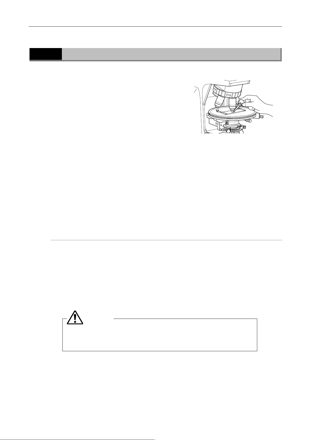
Objectives marked “oil” are oil-immersion type
objectives. These objectives are used with
immersion oil (option) between the specimen and
the tip of the objective.
Bubbles in the oil will adversely affect the viewing
of the image. Be careful to prevent bubbles from
forming. To check for air bubbles, fully open the
field diaphragm and aperture diaphragm, remove
the eyepiece, and examine the pupil (bright round
section) of the objective inside the eyepiece tube.
If it is difficult to ascertain the presence of bubbles,
place the Bertrand lens into the optical path. Then,
check for air bubbles while turning the Bertrand
lens focus ring to change the focus. (P.48):
• Turn the nosepiece slightly to move the oil-immersed objective back and forth once or
twice. (In the case of the condenser, gently turn the condenser focus knob to move the
condenser up and down slightly.)
• Apply more oil.
• Remove the oil and replace it with new oil.
Use as little oil as possible (just enough to fill the space between the tip of the objective and the
specimen, or between the tip of the condenser and the specimen). If too much oil is applied, the
excess oil will flow onto the stage or around the condenser.
Wipe off oil
Any oil remaining on the oil-immersion objective or adhering to the dry-type objective will
noticeably degrade image quality. After use, thoroughly wipe off all oil, and make sure that no oil
remains on the tips of other objectives. Oil on the condenser should also be wiped away carefully
after use.
Use petroleum benzine to wipe off immersion oil. For optimum results, we recommend following
up petroleum benzine with absolute alcohol (ethyl or methyl alcohol).
If petroleum benzine is unavailable, use methyl alcohol alone. However, methyl alcohol does not
clean as well as petroleum benzene, it will be necessary to wipe the surface repeatedly. (Usually,
three or four times are sufficient to clean the lenses.)
CAUTION
When using petroleum benzine or absolute alcohol, always follow the
instructions provided by the manufacturer. These liquids are highly
flammable and must be kept away from flames and sparks.
43
Page 46

Chapter 3 Individual Operations
3.15 Water Immersion Operation
3.15
Wipe off water
Water Immersion Operation
Objectives marked “WI” or “W” are water-immersion type objectives. These objectives are used
with immersion water (distilled water or physiological saline) applied between the specimen and
the tip of the objective. Microscopy procedures are the same as for oil-immersion type
objectives.
Since water evaporates readily, monitor the immersion water during observation. Avoid using
too much water, since excess water will flow onto the stage and around the condenser,
promoting corrosion.
After use, wipe off water from the tip of the objective and condenser, then follow up by wiping
with absolute alcohol.
If you observe water stains, apply a small amount of neutral detergent and wipe gently, then
follow up with absolute alcohol.
44
Page 47
Chapter 3 Individual Operations
3.16 Polarization Microscopy
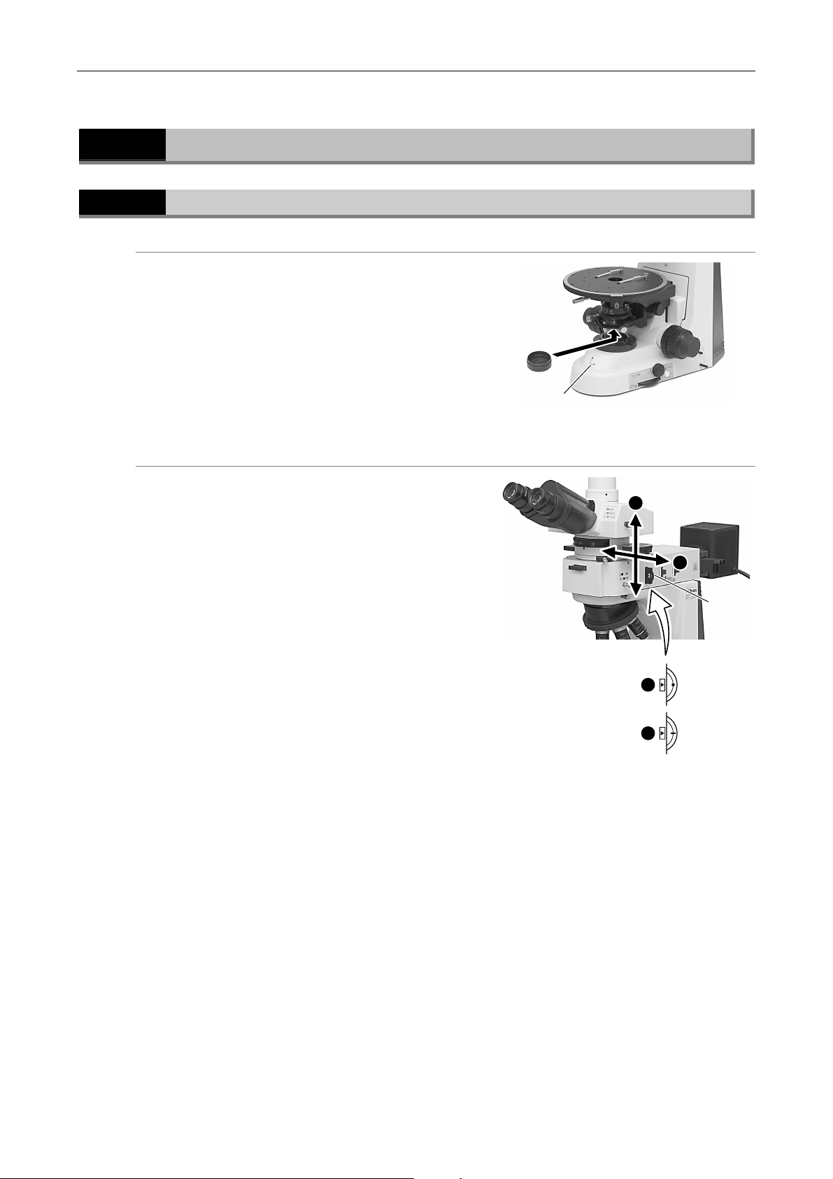
3.16
3.16.1
Polarizer for the diascopic microscopy
Polarizer for the episcopic microscopy
Polarization Microscopy
Operation of the Polarizers
To perform the diascopic polarization microscopy,
attach the polarizer for the diascopic microscopy at
the bottom of the condenser.
The orientation indicator (a circle mark on the outer
frame of the polarizer) must be facing toward the
operator. For farther information, refer to P.47.
To perform episcopic polarization microscopy,
attach the polarizer for the episcopic microscopy
into the epi illuminator.
Insert the polarizer slider with the orientation index
facing front side (eyepiece side).
Pushing the polarizer slider in to the first clickstop
position inserts the empty hole into the optical
path. Pushing it further in to the second clickstop
position inserts the polarizer into the optical path.
Dia polarizer
Orientation plate
2
1
Epi
polarizer
Set the orientation of the polarizer by turning the
polarizer rotating ring.
Polarizer orientation
(Polarizer rotating ring)
1
2
Lateral
direction
Vertical
direction
45
Page 48
Chapter 3 Individual Operations
3.16 Polarization Microscopy
3.16.2
Operation of the Analyzer
Attach/detach the analyzer
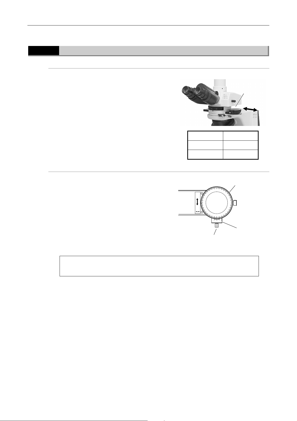
The intermediate tube has the analyzer slider. The
analyzer can be placed into the optical path with
the operation of the slider.
To place the analyzer into the optical path, pull out
the slider. To remove the analyzer from the optical
path, push in the slider.
The analyzer is designed to be inserted from the
right side in normal use, but it can be inserted from
the left. In the later case, its scale displays the
opposite way. Be careful.
Rotate the analyzer
The analyzer slider has a rotating dial. The
orientation of the analyzer can be rotated with it.
To adjust the analyzer, loosen the analyzer rotation
clamp screw and rotate the rotating dial.
The angle of rotation can be read from 0 to 180
degrees in steps of 0.1 degrees with the two
vernier scales.
The intermediate tube also has a de-polarizer. So, you can use the
photomicrography devices independently of the orientation of the polarizer.
Pulled out IN
Push in OUT
OUT
Analyzer rotation
clamp screw
Analyzer
slider
Slider Analyzer
110
120
150
160
170
Analyzer
rotating dial
130
140
Vernier
90
100
80
70
A
60
50
0.
40
IN
30
20
10
0
10
0
46
Page 49
Chapter 3 Individual Operations
3.16 Polarization Microscopy
3.16.3
Azimuth adjustment of the polarizer and analyzer
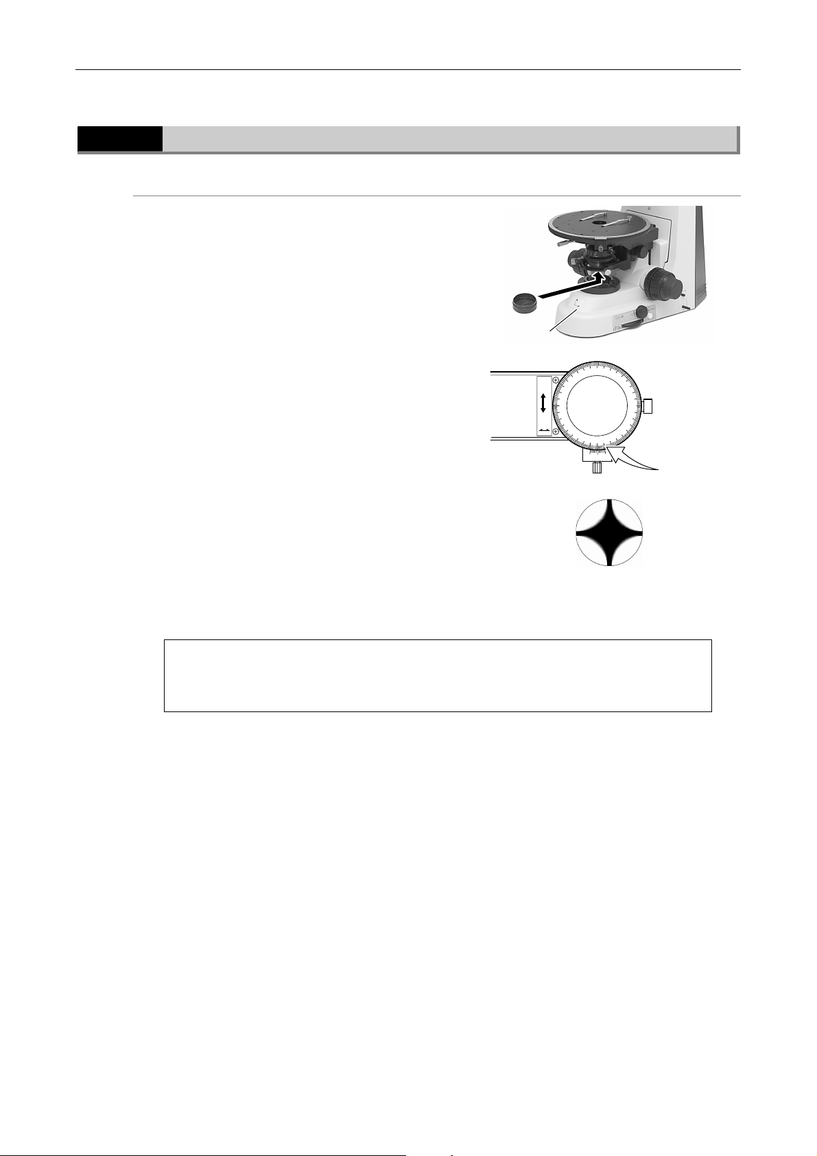
For the diascopic observation
(1) Push in the analyzer setting knob to move the
analyzer out of the optical path.
(2) Focus on the specimen.
(3) Pull out the analyzer setting knob to move the
analyzer into the optical path.
(4) Turn the analyzer rotation dial and align at
the “0” position on the scale.
(5) Move the dia polarizer into the optical path.
(6) Move the specimen out of the optical path.
(7) Move the Bertrand lens into the optical path.
The pupil of the objective will then be visible
through the eyepiece. Turn the dia polarizer
and adjust so that the dark cross image
appears in the pupil as shown in the figure.
This is so-called the crossed Nicols position,
where the orientations of the polarizer and
analyzer coincide with those of the orientation
plate on the top of the microscope base (the
polarizer, P, is in the X direction and the
analyzer, A, is in the Y direction).
Dia polarizer
Orientation
plate
A
OUT
70
60
50
0.
40
IN
30
90
100
80
110
20
160
170
10
0
10
0
Dark cross
120
150
130
140
Analyzer
scale: 0
It should be noted that the X direction is explained as that of the analyzer and Y
direction as that of the polarizer in some commercially available technical
manuals and reference books.
(1) Push in the analyzer setting knob to move the analyzer out of the optical path.
(2) Place a dummy specimen. It must have high reflectance with optical isotropy, for
example a mirror. And then, focus on the specimen.
(3) Pull out the analyzer setting knob to move the analyzer into the optical path.
(4) Turn the analyzer rotation dial and align at the “0” position on the scale.
(5) Push in the polarizer slider on the epi illuminator to place the epi polarizer into the
optical path.
(6) Move the Bertrand lens into the optical path. Turn the polarizer rotating ring on the
epi polarizer and adjust so that the dark cross image appears in the pupil as shown in
the figure.
47
Page 50
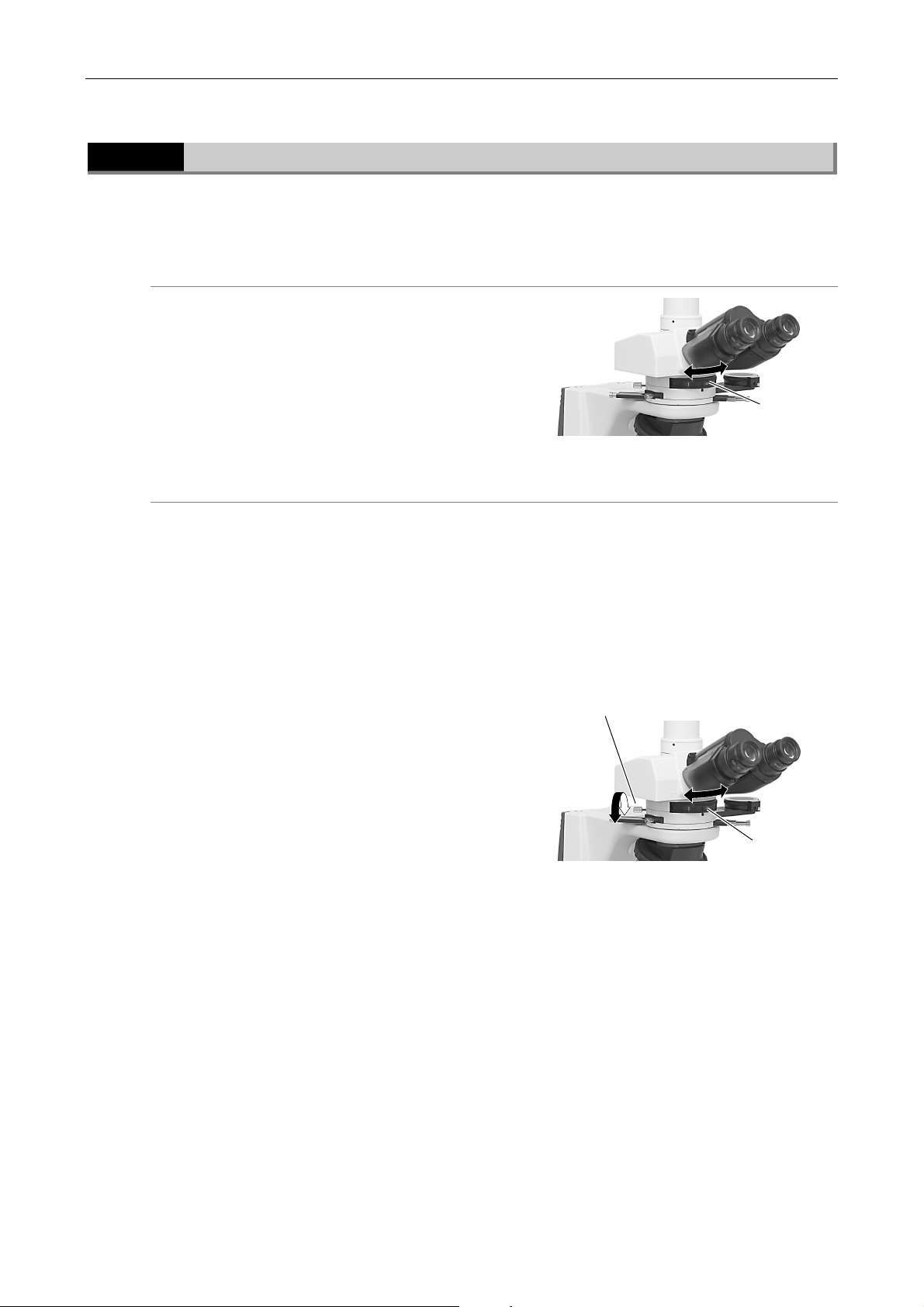
Chapter 3 Individual Operations
3.16 Polarization Microscopy
3.16.4
Setting the Bertrand lens
Focusing and centering the Bertrand lens
Bertrand Lens Operation
The intermediate tube has the Bertrand lens. The Bertrand lens can be placed into the optical
path to perform the conoscope observation.
Put the Bertrand lens turret in the “B” position to
move the Bertrand lens into the optical path.
Put the Bertrand lens turret in the “O” position to
remove the Bertrand lens from the optical path.
The objective pupil positions vary by magnification and type. So, when objectives are switched,
the Bertrand lens must be focused for each time.
Besides, the Bertrand lens must be centered so that it is aligned to the optical path of the
objective. Note that you need not center the Bertrand lens each time if you have centered the
objective already. (P. 42)
Bertrand lens
turret
In this adjustment, the aperture diaphragm image is used in the same manner as the condenser
lens adjustment. Do as follows:
(1) Refer to “2.1 Diascopic Bright-Field
Microscopy” to focus on the specimen. And
then, focus and center the condenser.
(2) Move the Bertrand lens into the optical path.
(3) Stop down the aperture diaphragm of the
condenser to get a diaphragm image into
view.
(4) Perform the focusing for the Bertrand lens.
Adjust the Bertrand lens focus ring on the
polarizing intermediate tube to get a clear
image of the diaphragm.
(5) Fully stop down the aperture diaphragm of
the condenser.
(6) Center the Bertrand lens. Rotate two
centering screws on the polarizing
intermediate tube so that the diaphragm
image comes to the center of the field of
view.
Bertrand lens
centering screws
Bertrand lens
focus ring
48
Page 51
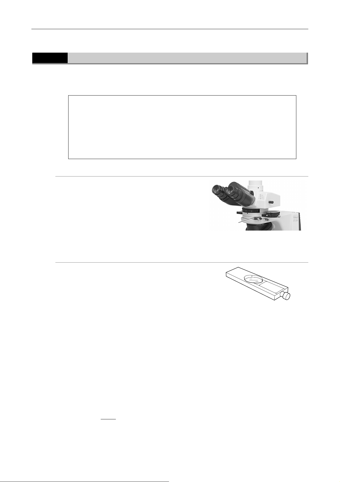
Chapter 3 Individual Operations
3.16 Polarization Microscopy
3.16.5
P-CL 1/4λ & tint plate
P-CL 1/4λ & Tint Plate
The intermediate tube has a slot for the P-CL 1/4λ & tint plate. It is used not only for the plate
but also for the optional P-CS Senarmont compensator or P-CQ quartz wedge to perform the
retardation measurement.
To use an objective of 10X or higher magnification in standard observation, place the top
lens of the P swing-out condenser into the optical path or pull out the slider of the slide
condenser.
To perform the retardation measurement or to perform evaluation by interference color, the
illumination light must be as parallel to the optical axis as possible. So, the condenser
aperture diaphragm must be stopped down or the top lens of the P swing-out condenser
must be swung out (the aperture diaphragm is fully opened) even if an objective of 10X or
higher is used.
The P-CL 1/4λ & tint plate has an empty hole in the
center. By pushing it into the slot, the sensitive
color plate (530 nm) is brought into the optical
path. Pulling it out brings the 1/4λ plate into the
optical path.
This plate is used for recognition of very weak
birefringence and the determination of X' and Z' of
the specimen.You can measure retardation of light
up to 1λ with the following steps.
P-CL 1/4 λ &
tint plate
P-CS Senarmont compensator
Remove the P-CL 1/4λ & tint plate from the slot of
the intermediated tube and insert the P-CS
Senarmont compensator into the slot.
You can measure retardation of light up to 1λ with
the following steps.
1 Determination of extinction position
Rotate the stage with the specimen under the crossed Nicols to find the direction where the
part of the specimen to be measured appears darkest.
2 Determination of subtraction position
Rotate the stage 45° from the extinction position to the diagonal position. If the interference
color changes toward the higher order side, rotate the stage another 90°.
3 Measurement
Place the GIF filter on the field lens and replace the P-CL 1/4λ & tint plate with the P-CS
Sénarmont compensator. Rotate the analyzer so that the section of the specimen to be
measured becomes darkest. When the rotation angle of the analyzer at that time is taken to
be theta (θ) degrees, then retardation (R) (nm) is determined with the following formula:
R = θ λ(λ: wavelength)
180
The value of λ when using the GIF filter is 546 nm.
P-CS senarmont compensator
49
Page 52
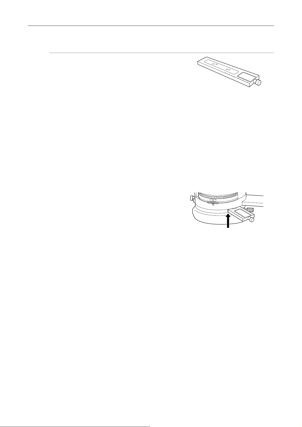
Chapter 3 Individual Operations
3.16 Polarization Microscopy
P-CQ quartz wedge
The P-CQ quartz wedge is used by inserting it into
the slot of the intermediate tube in place of the
P-CL 1/4λ & tint plate.
The quartz wedge is engraved with a scale and can
be used for rough measurement of retardation in
the range of 1λ to 6λ.
P-CQ quarts wedge
1 Determination of extinction position
Rotate the stage with the specimen under the crossed Nicols to find the direction where the
part of the specimen to be measured appears darkest.
2 Determination of subtraction position
Rotate the stage 45° from the extinction position to the diagonal position (direction where
the specimen appears brightest). Insert the P-CQ quartz wedge into the slot of the
intermediate tube and confirm that the interference color of the section of the specimen to
be measured changes toward the lower order side. If the interference color changes toward
the higher order side, rotate the stage another 90°.
3 Measurement
Move the section of the specimen to be measured
to the center of the crosshairs of the eyepiece.
Next, slide the P-CQ quartz wedge along the slot
and observe that the interference color sequentially
changes. Stop sliding the quartz wedge where the
dark stripe covers the section of the specimen to
be measured. Reading the value from the quartz
wedge scale at that time can make a rough
measurement of retardation.Retardation can be
measured even more accurately by using the P-CS
Sénarmont compensator in combination with the
P-CQ quartz wedge.
Read the scale.
50
Page 53
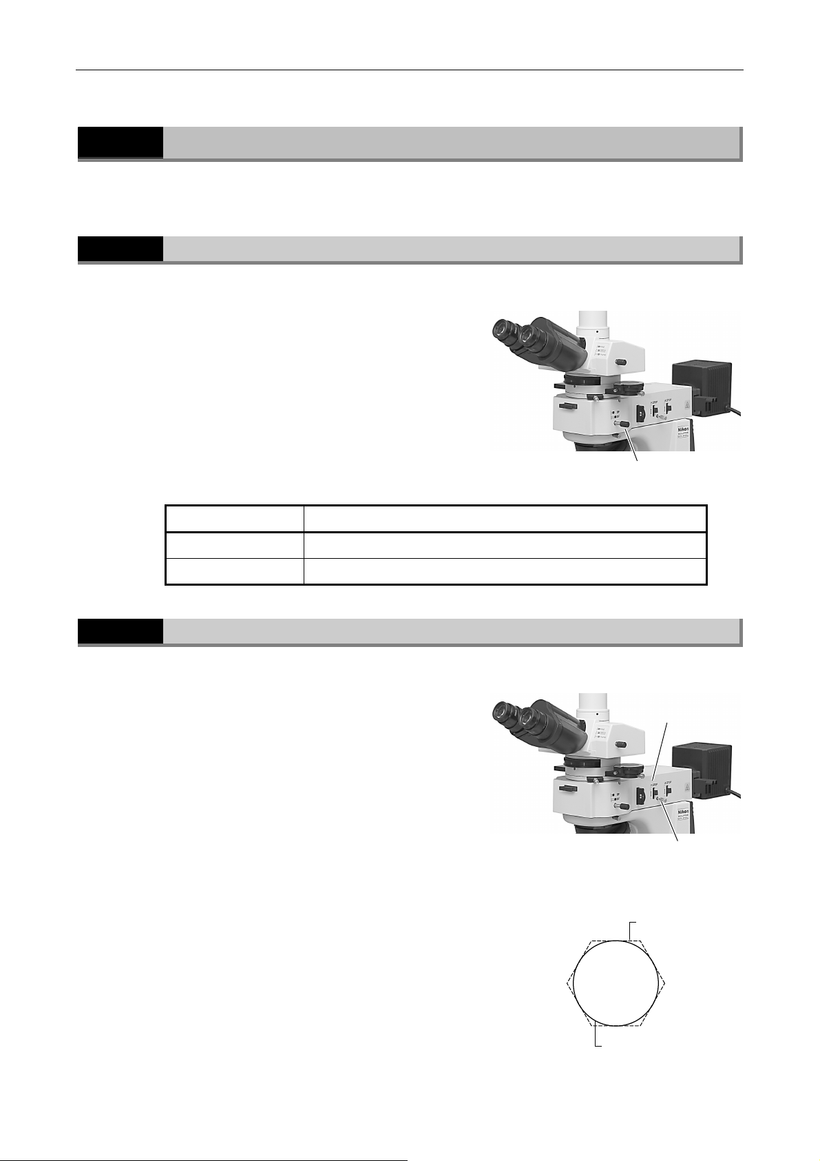
Chapter 3 Individual Operations
g
3.17 Episcopic Microscopy
3.17
3.17.1
Episcopic Microscopy
To perform episcopic microscopy, attach the LV-UEPI universal epi illuminator to the microscope.
Switching the Episcopic Illumination
You can switch the illumination between the
bright-field and the dark-field to be used for the
episcopic microscopy by operating the illumination
selection lever on the right side of the epi illuminator.
For the bright-field, push in the lever.
When the lever is pulled out, the dark-field is specified.
But you cannot perform the episcopic dark-field
microscopy using this microscope.
* The dark-field setting (DF) is used for the diascopic
illumination.
Lever position Illumination method
Illumination selection lever
3.17.2
Push in (BF) Episcopic bright-field ( and Episcopic polarization microscopy)
Pull out (DF) Diascopic illumination (The dark-field microscopy is not available.)
Field Diaphragm in the Epi Illuminator
The field diaphragm restricts illumination to the area of
the specimen that is being viewed. Operating the field
diaphragm open/close lever changes the size of the
field diaphragm. For normal observation, the size of
the diaphragm should be such that it is just outside (or
inside) the edge of the viewfield. If a broader area than
necessary is illuminated, stray light will enter the
optical system, creating flaring, and reducing the
contrast of the optical image.
Appropriate field diaphragm settings are particularly
important for photomicrography and digital image
capturing. In general, good results will be obtained by
stopping down the field diaphragm to settings slightly
wider than the area to be reproduced within the photo
frame or monitor display.
Field diaphragm
open/close lever
Field diaphragm
centering screw
(both side)
Field diaphragm
ima
e
Eye piece viewfield
51
Page 54
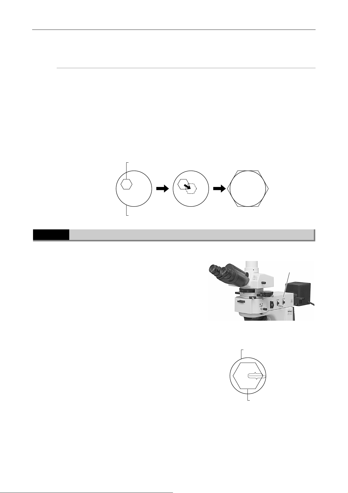
Chapter 3 Individual Operations
pen/
3.17 Episcopic Microscopy
Centering the field diaphragm
(1) Perform steps in “2.4 Episcopic Microscopy (with the Epi Illuminator Option)” and focus on
the specimen using the 10X objective under the episcopic illumination.
(2) Lower the field diaphragm open/close lever to stop down the field diaphragm.
(3) Turn the field diaphragm centering screws (on both sides) so that the field diaphragm
image is positioned in the center of the view field.
(4) Adjust the field diaphragm image with the field diaphragm open/close lever and centering
screws so that it inscribes the view field.
(5) To observe the specimen, raise the field diaphragm open/close lever so that the field
diaphragm image circumscribes the view field.
Field diaphragm image
3.17.3
Eye piece viewfield
Aperture Diaphragm in the Epi Illuminator
Since the aperture diaphragm is for adjusting the
numerical aperture of the illumination system, this
diaphragm is related to the resolution, contrast, and
depth of focus of the optical image.
The aperture diaphragm open/close lever will change
the opening of the aperture diaphragm. Remove one of
the eyepieces, and then adjust the aperture diaphragm
opening while observing the objective's exit pupil in the
eyepiece tube. Generally, the aperture diaphragm
should be adjusted to about 70 to 80% of the
numerical aperture of the objective.
The diaphragm image may not appear in the case of
samples with low reflectivity. In this case, change to a
sample with a near-polished surface.
Aperture diaphragm
o
close lever
Eye piece viewfield
70~80
100
Aperture diaphragm image
52
Page 55
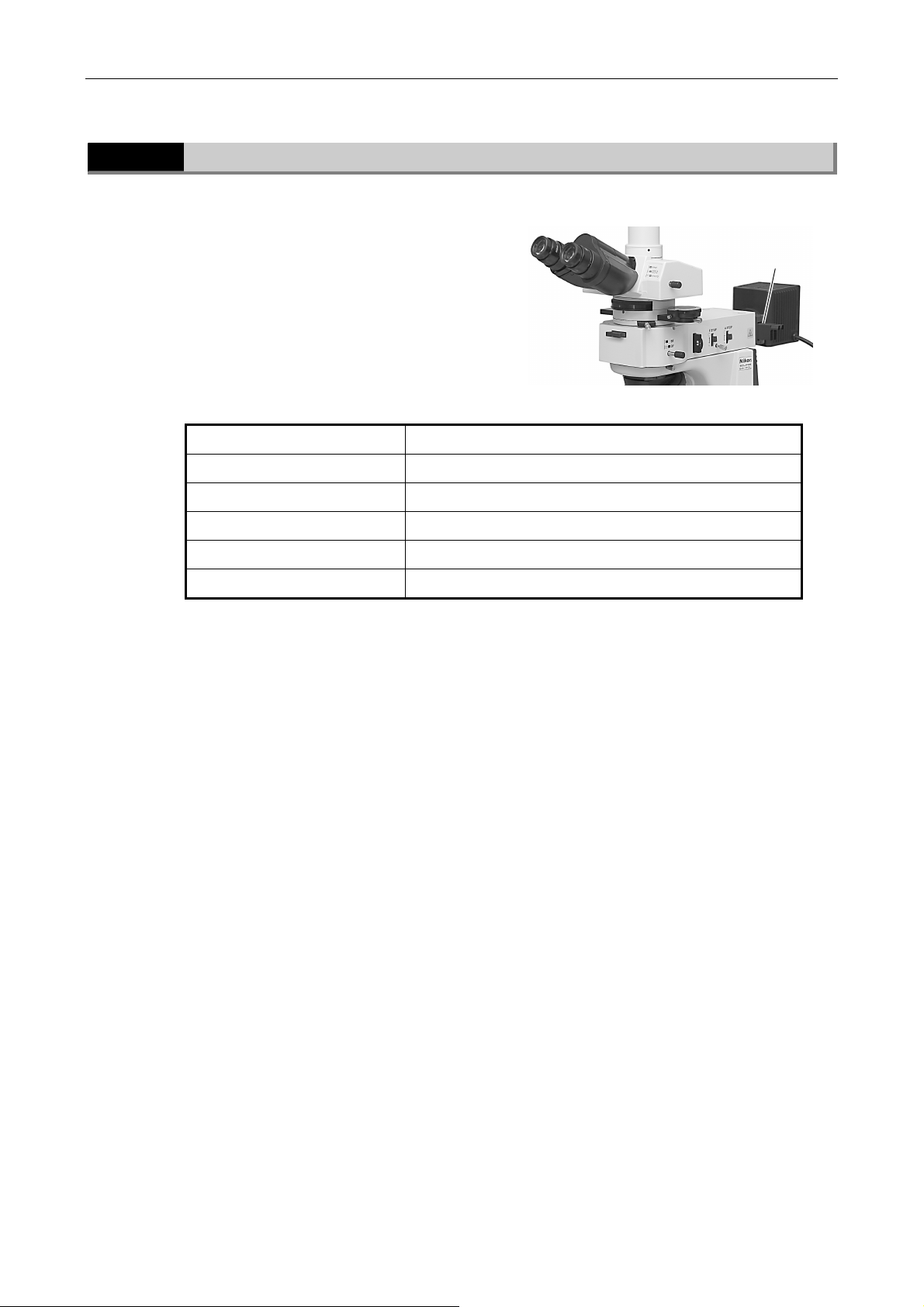
Chapter 3 Individual Operations
3.17 Episcopic Microscopy
3.17.4
Operating Filter on the Epi Illuminator
The LV-UEPI universal epi illuminator has two filter
sliders. You can use suitable filters by operating the
filter sliders.
Filters Usage
NCB11 (color balancing filter) For color balance adjustment and color photomicrography
ND4 (ND filter) Brightness adjustment (transmittance 25%)
ND16 (ND filter) Brightness adjustment (transmittance 6%)
GIF (green interference filter) Contrast adjustment
IF (interference filter) For interference
Filter sliders
53
Page 56

Chapter 3 Individual Operations
3.18 Image Capturing
3.18
3.18.1
3.18.2
Image Capturing
Microscopy images can be captured by attaching a camera head to the trinocular eyepiece tube.
For detailed information, refer to the operating manual provided with the camera head or
camera control software.
Proper adjustment of light intensity and focus on the microscope are important for obtaining
clear images. Listed below are key considerations in capturing clear images.
Adjusting Light Intensity
• Lamp voltage: If accurate color reproduction is critical, set the brightness control
knob to a midpoint setting and use the ND filters to make brightness
adjustments.
• Filter: Place a commercially available color compensation filter on the filter
pocket at the microscope base, as necessary.
Adjusting the Condenser
• Focus and center the condenser always.
3.18.3
3.18.4
• Center the annular diaphragm for the phase contrast microscopy.
• For normal operations, set the diaphragm aperture to 70 to 80% of the N.A. of the
objective.
Confirming the Photomicrographic Range
The image on the monitor represents the photomicrographic range.
Confirming the Focus
Check the focus by viewing through the eyepiece and viewing the monitor. If the focal positions
for the two images differ, adjust the focal position adjustment screw at the camera port.
54
Page 57

Chapter 3 Individual Operations
3.18 Image Capturing
3.18.5
3.18.6
Making Adjustments to Keep out Ambient Light
• Field diaphragm: Stop down the diaphragm to a setting just slightly wider than the
area shown on the monitor.
• Eyepiece: Cover the eyepiece with a piece of cloth.
Anti-vibration Measures
If the exposure is less than 1/8 of a second, reduce light intensity with ND filters to make
exposures longer than 1/8 of a second. (If accurate color reproduction is not important, you can
use the brightness control knob to reduce light intensity.)
55
Page 58
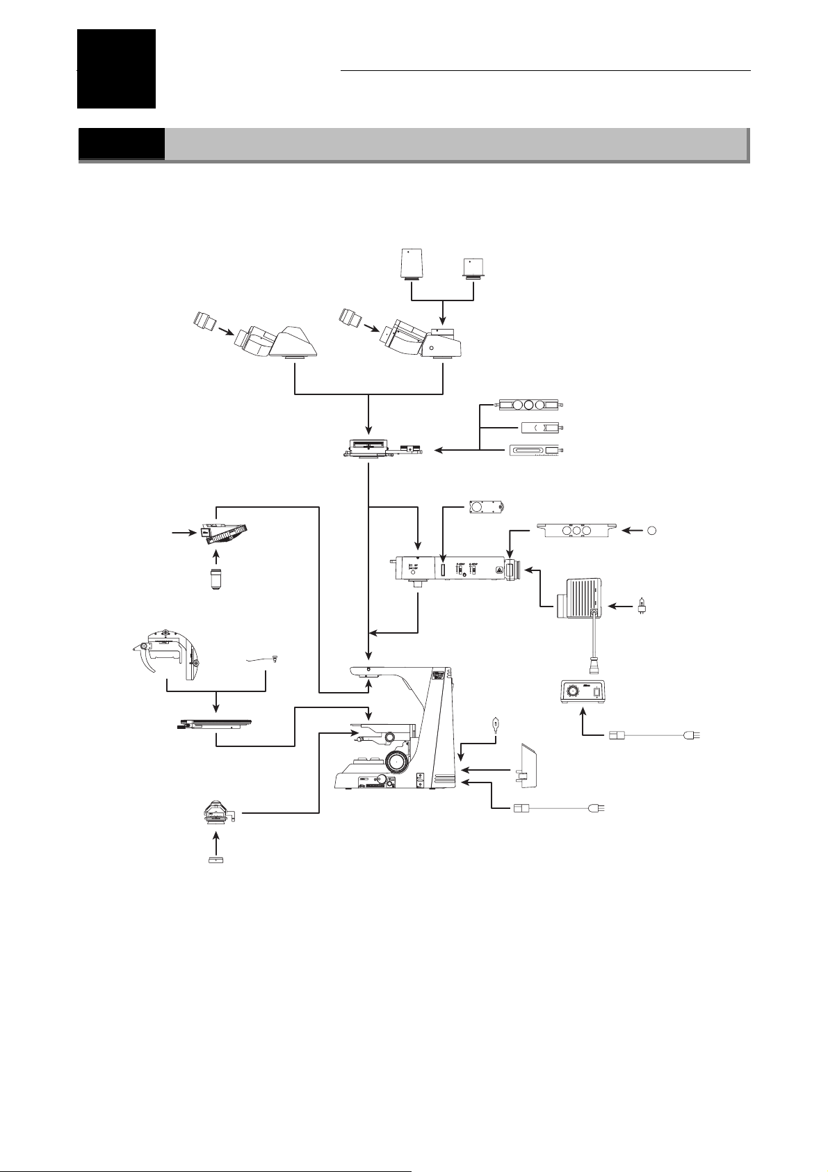
4
Assembly
4.1
Eyepieces
Polarizing intermediate tube
(with analyzer slider)
DIN slot
Attachable
mechanical stage
40 50 60 70 80
System Configuration
TV vertical
tube adapter
Eyepieces
Binocular
eyepiece tube
Quintuple
centering
nosepiece
Objectives
Specimen
holders (x2)
3020100
or
Trinocular
eyepiece tube
TV vertical
tube adapter
0.55X
or
Polarizer
slider
Epi illuminator
6V 30W
halogen lamp
P-CL 1/4λ & tint plate
P-CS Senarmont compensator
P-CQ quartz wedge
Filter slider (x2)
Lamphouse
Lamp cable
POWER
MIN. MAX.
Lamp power
supply
Filters
12V 50W
halogen lamp
Circular
graduated stage
Dia polarizer
P swing-out
condenser
A
0.90
JAPAN
0.20.8 0.6 0.4
0
1
0
0
9
2
0
0
8
3
0
0
7
4
0
0
6
50
50i POL main unit
56
Power cord
Lamp cover
Power cord
Page 59
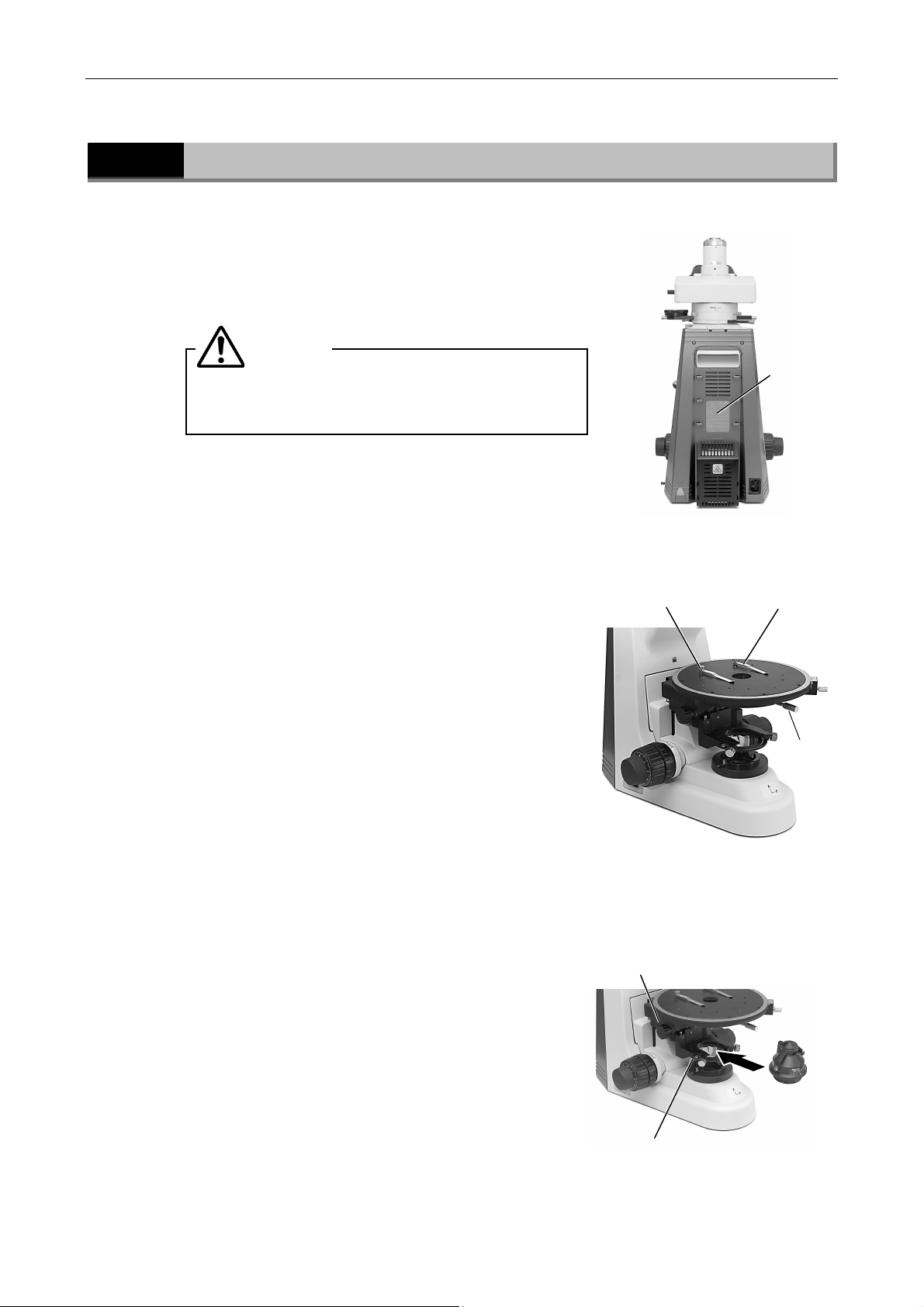
Chapter 4 Assembly
4.2
1
2
Assembly Procedure
Checking the input voltage
Make sure that the input voltage indicated on the back
panel of the microscope is the same as the voltage
provided in your area.
Attaching the circular graduated stage
(1) Remove the cushioning material from the substage
CAUTION
If the indicated voltage is different, do not
use the microscope. Contact your nearest
Nikon representative.
section and turn the coarse focus handle until the
elevating section is brought to the lowermost
position.
Specimen holder
Input
voltage
indication
Specimen holder
(2) Loosen the clamp screw for the circular graduated
stage.
(3) Place the circular graduated stage on the substage.
The stage must be level when fixed and its clamp
screw must be located facing the front side.
(4) If necessary, attach the specimen holders into the
hole on the stage.
For information about the optional attachable
mechanical stage, see “3.5.2 Attachable Mechanical
Stage (Option).”
Attaching the condenser
3
To perform the polarization microscopy, the P swing-out
condenser must be attached.
(1) Turn the coarse focus knob until the elevating
section is raised to the uppermost position.
(2) Turn the condenser focus knob until the substage is
brought to the lowermost position.
(3) Insert the condenser and adjust so that it faces
toward the front. Secure in place with the tool
stored in the back of the microscope.
(4) Turn the condenser focus knob until the substage is
raised to the uppermost position.
Condenser focus knob
Clamp screw for the condenser
Clamp screw
for the stage
57
Page 60
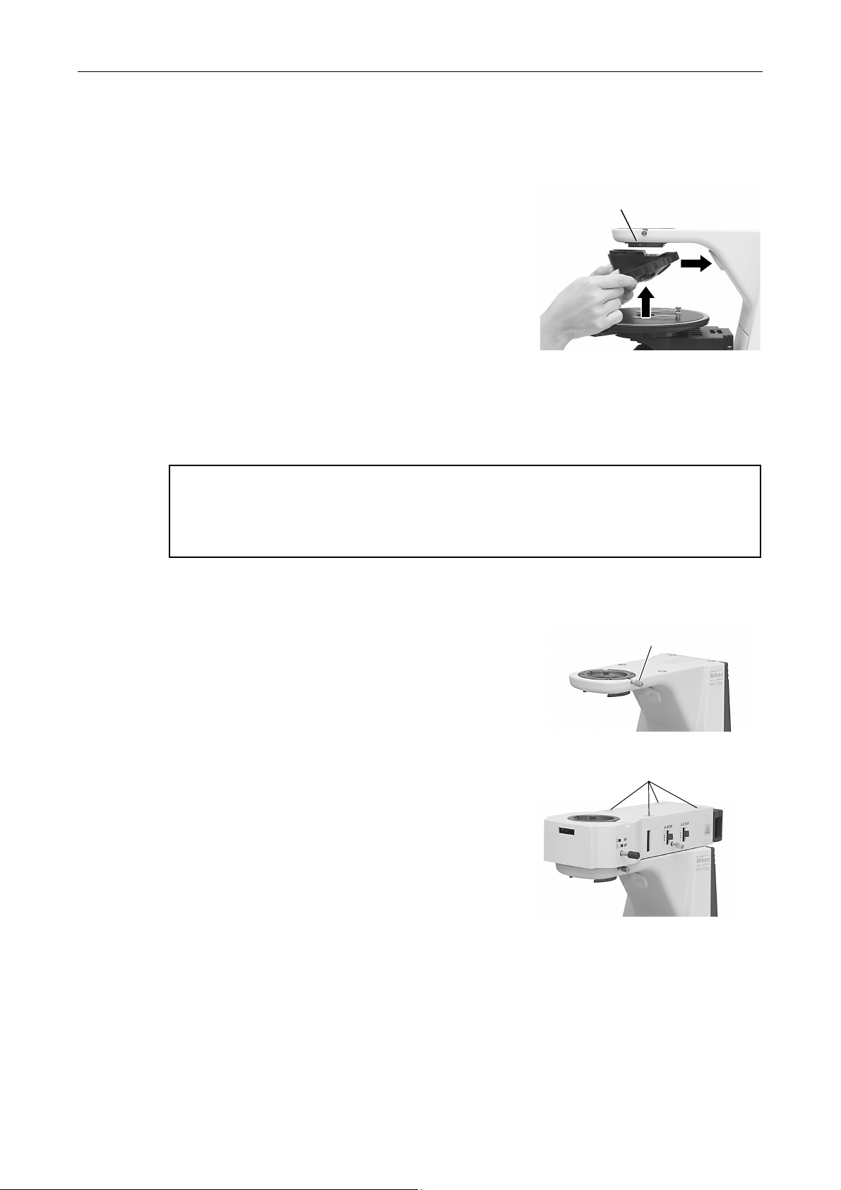
Chapter 4 Assembly
Attaching the nosepiece
4
Attach the P-N quintuple centering nosepiece on this
microscope.
(1) Lift the nosepiece from a position just forward of
the point directly below the fitting part and slide
toward the back to attach.
Continue sliding the nosepiece until its front
position is aligned with that of the fitting part.
(2) Secure in place with the tool stored in the back of
the microscope.
Attaching objectives
5
Lower the stage completely. Screw objectives into the nosepiece so that the magnification
increases with the clockwise rotation (as viewed from above the microscope) of the nosepiece.
Caution when removing objectives
When removing the objectives, remove the sample from the stage. Lower the stage
completely, and hold each objective using both hands so that it does not fall during the
removal.
Clamp screw for the nosepiece
Attaching the epi illuminator (for the episcopic microscopy)
6
The LV-UEPI universal epi illuminator can be attached to
this microscope.
(1) Loosen sufficiently the illuminator clamp screw on
the side of the microscope arm.
(2) Mount the illuminator onto the microscope arm and
fix it by tightening the illuminator clamp screw.
(3) Secure the illuminator on the microscope arm. Do
this by tightening the four hex screws supplied with
the illuminator using the hexagonal wrench.
(4) Cover the screw holes with the protective stickers
supplied with the illuminator.
(5) Refer to the instruction manual for the epi
illuminator. And attach the filter slider, polarizer
slider, dummy slider, and so on to the epi
illuminator.
Illuminator clamp screw
Hex screws to fix the
epi illuminator
Epi illuminator in place
58
Page 61
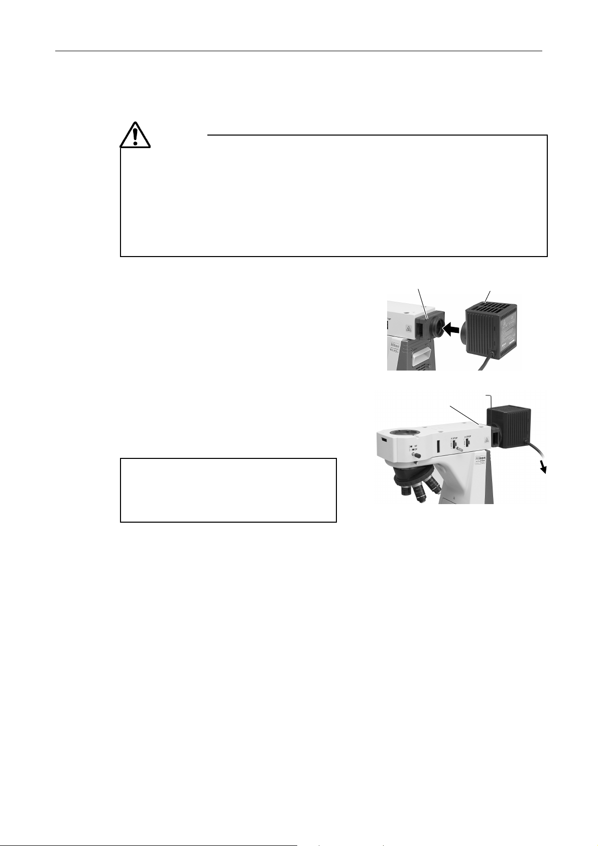
Chapter 4 Assembly
p
T
7
Attaching the lamphouse for the epi illuminator
CAUTION
• To prevent electrical shock and damage to the microscope, always turn off the
power switch (flip it to the “O” side) and unplug the power cord from the
outlet before attaching or detaching the lamphouse.
• To prevent burn injury, allow the lamp and the lamphouse to cool down
sufficiently (for at least 30 minutes after the lamp is turned off), before
replacing the lamp.
• Use the Nikon LV-LH50PC halogen lamphouse for the lamphouse.
(1) Loosen the clamp screw on the top side of the
lamphouse connector by using the hexagonal
screwdriver.
(2) Mount the lamphouse to the connection port on
the rear of the illuminator and press the
lamphouse as far as it goes.
(3) Using the hexagonal screwdriver supplied with
the microscope, tighten the clamp screw on the
top of the connection port of the lamphouse to
secure it.
(4) Connect the cable of the lamphouse with the
connector on the power supply device using an
extension cord.
Mount the lamphouse
ighten the clamp csrew.
house
lam
The power line connection for the power supply
device must be performed after attachment steps
for other devices. For details, refer to the
instruction manuals provided with the power
supply device.
To power
supply
59
Page 62
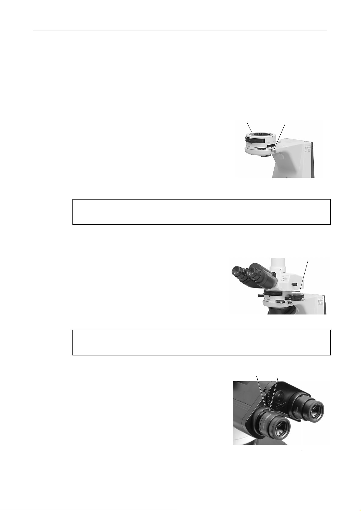
Chapter 4 Assembly
yep
yep
8
9
Attaching the polarizing intermediate tube
(1) Loosen sufficiently the clamp screw for the intermediate tube (or the illuminator) on the
microscope arm.
Use the tool provided with the microscope to loosen the clamp screw for the epi illuminator.
(2) Fit the circular dovetail of the polarizing
intermediate tube into the circular dovetail groove
of the microscope arm (or of the epi illuminator).
When fitting, insert the positioning pin on the
polarizing intermediate tube into the receiving
groove on the arm (or the epi illuminator).
(3) Secure the polarizing intermediate tube by
tightening the clamp screw.
Use the tool provided with the microscope to
tighten the clamp screw for the epi illuminator.
Remove any looseness between the positioning pin and groove by pushing in the
intermediate tube while rotating in the clockwise direction.
Attaching the eyepiece tube
(1) Completely loosen the eyepiece tube clamp screw
on the intermediate tube with the provided tool.
(2) Fit the circular dovetail of the eyepiece tube into
the circular dovetail groove of the intermediate
tube.
Plarizing intermediate
tube
Clamp screw for
the e
Clamp screw for
the e
iece
iece tube
10
When fitting, insert the positioning pin on the
eyepiece tube in the receiving groove on the
intermediate tube.
(3) Secure the eyepiece tube by tightening the clamp
screw.
Remove any looseness between the positioning pin and groove by pushing in the eyepiece
tube while rotating in the clockwise direction.
Attaching the eyepieces
Attach eyepieces of the same magnification. Attach the
eyepiece containing crosshairs on the right side so as to
be viewed with the right eye.
The sleeve has positioning pins. Insert the eyepieces by
aligning the notches of the eyepieces with the
protrusions of the eyepiece tube sleeves.
※
If necessary, insert the optional rubber eyeguard so
that they fit into the grooves around the outside of
the eyepieces.
Protrusion
Notch
Eyepieces attached in place
60
Page 63
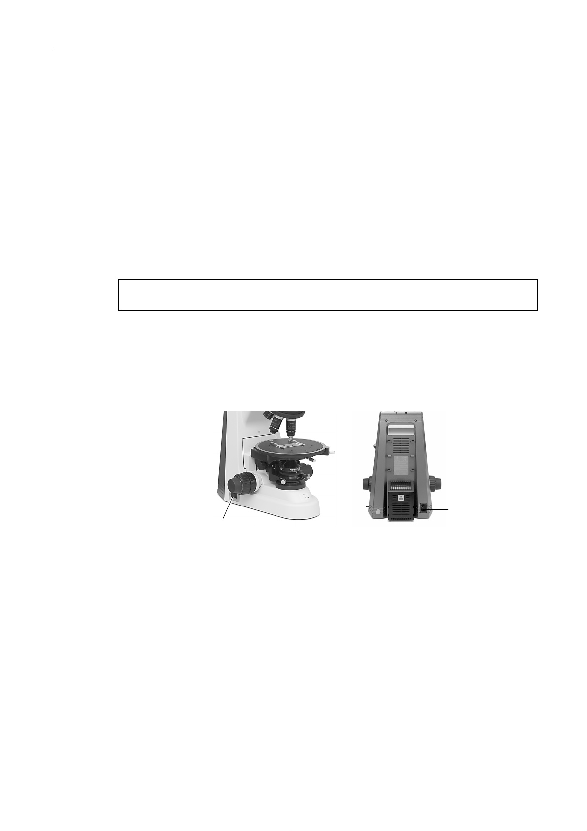
Chapter 4 Assembly
11
12
Attaching a camera (for the trinocular eyepiece tube)
To attach a photomicrography device such as a camera onto the vertical tube of the trinocular
eyepiece tube, you must use two adapters: First, attach the TV vertical tube adapter or the TV
vertical tube adapter 0.55X onto the trinocular eyepiece tube. Second, attach a suitable adapter
for the camera mount part (C mount adapter or so on) onto the TV vertical adapter.
Check the mount part type of your camera and prepare the suitable adapter beforehand.
(1) Mount the TV vertical tube adapter or the TV vertical tube adapter 0.55X onto the vertical
tube section of the trinocular eyepiece tube.
(2) Attach the suitable adapter for the camera onto the tip of the TV vertical tube adapter.
(3) Attach the camera head to the adapter tip.
(4) Attach the camera cable to the camera head.
Adjust the camera head position before using the camera.
Attaching the power cord
(1) Check to confirm that the microscope power switch is off.
(2) Insert the power cord into the AC inlet at the back of the microscope.
(3) Insert the other end of the power cord into a wall outlet.
AC inlet
The microscope assembly is now completed.
Power switch for
the microscope
61
Page 64
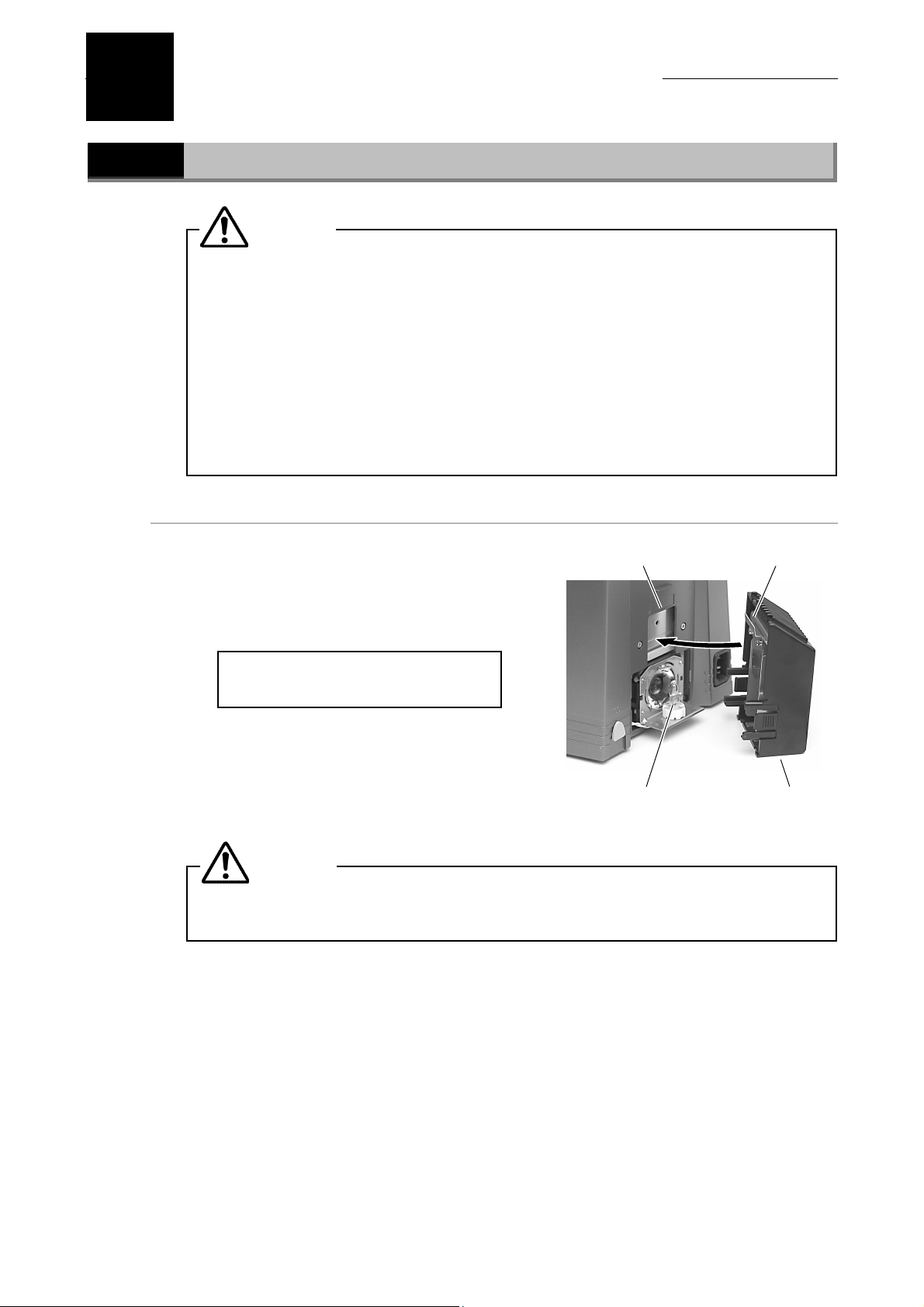
5
Replacing Consumables
5.1
Replacing the lamp for the diascopic illumination
(1) Remove the lamphouse cover on the back of
(2) Attach a new lamp.
(3) Replace the cover.
Replacing the lamp
CAUTION
• Be careful to avoid burns:
Wait until the lamp and nearby parts have cooled before attempting to
replace the lamp.
• Be careful to avoid electrical shock:
Turn off the power switch and unplug the power cord from the outlet.
• Be careful to avoid abnormal heat generation:
Use only the lamp specified.
• Be careful to avoid soiling:
Avoid touching the bare lamp bulb with bare hands. Soiling will reduce the
service life of the lamp.
the microscope. Remove the old lamp.
Avoid touching the bare lamp bulb with your
bare hands.
Use only the lamp specified (PHILIPS
5761).
Engage the cover hook in the slot on the rear
of the unit in the direction indicated by the
arrow in the figure.
CAUTION
Be sure to attach the lamphouse cover. Failure to do so may result in burns or
fire from the heat generated by the lamp.
Slot for cover hook
Lamp
Cover hook
Lamphouse cover
62
Page 65

Chapter 5 Replacing Consumables
5.1 Replacing the lamp
Replacing the lamp for the episcopic illumination
The lamp can be replaced without having to detach the lamphouse from the microscope.
Before starting the procedure below, be aware the following.
CAUTION
• To prevent electrical shock and damage to the microscope, always turn off
the power switch (flip it to the “O” side) and unplug the power cord from
the outlet before attaching or detaching the lamphouse.
• To prevent burn injury, allow the lamp and the lamphouse to cool down
sufficiently (for at least 30 minutes after the lamp is turned off), before
replacing the lamp.
• Use the Nikon LV-HL50W 12V 50W LONGLIFE halogen lamp or non-Nikon
12V 50W SHORTLIFE halogen lamp (model OSRAM HLX 64610, OSRAM HLX
64611, or PHILIPS 7027) for the lamp. If you wish to buy these lamps,
please contact your nearest Nikon representative.
• Do not touch the glass surface of the lamp with bare hands. Fingerprints or
grease on the bulb surface will reduce the illumination intensity of the
lamp. Wipe clean any fingerprints or grease attached to the surface.
• Securely attach the lamphouse cover to the lamphouse after replacing the
lamp. Never light the lamp with the lamphouse cover removed.
• When you dispose of the replaced lamp, do not break it up. Instead,
dispose of the used lamp as special industrial waste or dispose of it
according to the local regulations and rules.
63
Page 66
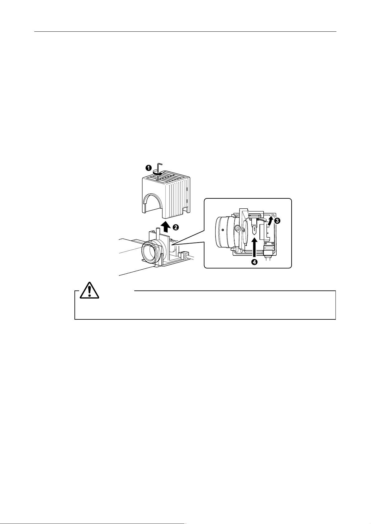
Chapter 5 Replacing Consumables
5.1 Replacing the lamp
(1) Loosen the lamphouse cover clamp screw using the hexagonal wrench.
(2) Remove the lamphouse cover.
(3) Push down the lamp clamp lever and remove the old lamp.
(4) With the lamp clamp lever held down, insert the electrodes of a new lamp into the pin
holes of the socket. Press the lamp as far as it goes, and then release the lamp clamp
lever to secure the lamp.
Be careful not to touch the glass surface with bare hands.
When releasing the lamp clamp lever, use care so that the lamp does not tilt.
(5) Close the lamphouse cover and secure it by tightening the clamp screw.
CAUTION
Be sure to attach the lamphouse cover. Failure to do so may result in burns or
fire from the heat generated by the lamp.
64
Page 67

6
Troubleshooting
When the product does not function properly, take appropriate action as described below. If the
problem is still not resolved after referring to "Troubleshooting," please contact your nearest Nikon
representative.
6.1
Problem Cause Countermeasure
The viewfield is invisible,
vignetted, or uneven in
brightness.
Dir t or dust is s e e n i n t h e
viewfield
The image quality is
poor (too much or too
little contrast, or poor
resolution).
Optical System
Some parts are attached incorrectly.
Some movable part is not moved
correctly.
The field diaphragm image is not
focused on the specimen surface.
The field diaphragm is stopped down
too far.
Dirt or dust exists on the lens or other
optical element, or on the container.
The Bertrand lens is in the optical
path
The top lens of the P swing-out
condenser is not positioned properly.
The P-CL, P-CS, or P-CQ plate is not
inserted correctly.
Dirt or dust exists on the lens or other
optical element, or on the container.
The field diaphragm image is not
focused on the specimen surface.
Dirt or dust exists on the lens or other
optical element, or on the container.
Objective correction ring does not
match the thickness of the
container’s bottom plate.
The field diaphragm image is not
focused on the specimen surface.
The cover glass is not suitable for the
objective.
The cover glass is too thick.
There is no oil on the tip of an oil
immersion type objective. The
specified immersion oil is not being
used.
There are bubbles in the immersion
oil.
There is immersion oil on the tip of a
dry type objective.
Attach the parts (nosepiece, condenser,
filters, lamp, and so on) correctly.
Move parts (optical path select lever,
nosepiece, filter slider and so on) to a
clickstop position.
Focus and center the condenser.
Open the field diaphragm so that it is just
outside of the viewfield.
Clean off the dirt. Use a clean container.
Place it out of the optical path.
Move them fully.
Move it to the correct position.
Clean off the dirt. Use a clean container.
Focus and center the condenser.
Clean off the dirt. Use a clean container.
Adjust the correction ring.
Focus and center the condenser.
Use a cover glass and an objective in the
correct combination.
Use the specified type of cover glass
(thickness: 0.17 mm).
Apply Nikon Immersion Oil.
Remove the bubbles.
Clean the components.
65
Page 68

Chapter 6 Troubleshooting
6.1 Optical System
Problem Cause Countermeasure
The nosepiece is not attached
correctly. Or its rotation has not
stopped at the click stop position.
The focus is uneven.
The image is elongated.
The image is tinged
yellow.
The image is too bright.
The brightness is
insufficient.
The specimen is not secured in place
on the stage surface.
The stage has been attached in out of
perpendicular.
The specimen is tilted relative to the
stage surface.
The nosepiece is not attached
correctly. Or its rotation has not
stopped at the click stop position.
The condenser has not been
centered.
The stage has been attached in out of
perpendicular.
The lamp voltage is too low.
No NCB filter is placed in the optical
path.
No ND filter is placed in the optical
path.
The lamp voltage is too high.
The condenser aperture diaphragm is
stopped down too far.
The field diaphragm image is not
focused on the specimen surface.
The optical path selection knob is not
set to the 100% eyepiece.
Attach the nosepiece correctly. And rotate
it to the click stop position.
Place the specimen properly on the stage.
Install the stage correctly.
Locate the specimen correctly on the
stage.
Attach the nosepiece correctly. And rotate
it to the click stop position.
Center the condenser.
Install the stage correctly.
Increase the lamp voltage with the
brightness control knob. Or, push the
preset switch.
Place it into the optical path.
Place it into the optical path.
Decrease the lamp voltage with the
brightness control knob.
It should normally set to 70 to 80% of the
numerical aperture of the objective.
Focus and center the condenser.
Set to the 100% eyepiece position.
66
Page 69
Chapter 6 Troubleshooting
6.2 Mechanical System
6.2
Problem Possible causes Remedy
The image is not in focus
although the objective is
raised to the highest
position.
Focusing is not possible
with high-power
objectives.
The objective strikes the
specimen when
changing from a
low-power objective to a
high-power objective.
When viewing through
the binocular eyepiece,
the image does not
resolve into a single
image.
Eye strain develops
while viewing.
Mechanical System
The stage has been attached
incorrectly.
The specimen is placed upside-down.
The cover glass is too thick.
The specimen is placed upside-down.
The cover glass is too thick.
The diopter adjustment has not been
performed.
The interpupillary distance has not
been adjusted.
The diopter adjustment has not been
performed.
The interpupillary distance has not
been adjusted.
The diopter adjustment has not been
performed.
The brightness is not suitable.
Install the stage correctly.
Set the specimen on the stage with the
cover glass facing up.
Use the specified type of cover glass
(thickness: 0.17 mm).
Set the specimen on the stage with the
cover glass facing up.
Use the specified type of cover glass
(thickness: 0.17 mm).
Perform the diopter adjustment.
Adjust the interpupillary distance.
Perform the diopter adjustment.
Adjust the interpupillary distance.
Perform the diopter adjustment.
Adjust the brightness with the brightness
control knob or ND filters.
6.3
Problem Possible causes Remedy
There is no power even
though the power switch
is on.
The lamp does not light.
The lamp burns out
quickly.
The lamp flickers; the
brightness is unstable.
Electrical System
The power cord is not connected, or
is connected improperly.
No lamp is attached, or the lamp has
burned out.
The lamp type is incorrect. Replace the lamp with a specified one.
The lamp has reached the end of its
operational life.
The power cord is not connected
securely.
The lamp has not been plugged into
its socket securely.
Connect it properly.
Replace the lamp with a specified one.
Replace the lamp with a new one.
Connect it properly.
Install the lamp correctly.
67
Page 70

7
Care and Maintenance
7.1
Lens Cleaning
Do not let dust, fingerprint, etc. get on the lenses. Dirt on the lenses, filters, etc. will adversely
affect the view of image. If any of the lenses get dirty, clean them as described below.
• Either brush away dust with a soft brush, or else gently wipe it off with a piece of gauze.
• Only if there are fingerprints or grease on a lens, dampen lightly a piece of soft, clean
cotton cloth, lens tissue, or gauze with absolute alcohol (ethyl or methyl) and gently wipe
off the dirt.
• When removing the immersion oil off from the objective, use only petroleum benzine. For
optimum results, we recommend following up petroleum benzine with absolute alcohol
(ethyl or methyl alcohol). If petroleum benzine is unavailable, use methyl alcohol alone.
However, methyl alcohol does not clean as well as petroleum benzine, it will be necessary
to wipe the surface repeatedly. (Usually, three or four times are sufficient to clean the
lenses.)
• Never use petroleum benzine to clean the entrance lens of the eyepiece tube or prism
surface of the eyepiece tube.
• Absolute alcohol and petroleum benzine are highly flammable. Be careful when handling
it, when around open flames, when turning the power switch on/off, etc.
• When using petroleum benzine or absolute alcohol, always follow the instructions
provided by the manufacturer.
7.2
7.3
Cleaning the Product
• We recommend that you use a piece of silicon cloth to clean this product.
• For persistent dirt, dampen a piece of gauze with neutral detergent and wipe gently.
• Using organic solvents could result in discoloration of the plastic parts.
Disinfecting the Product
• We recommend that you use 70% medical alcohol for normal disinfection of this product.
• In case of spillage of a specimen onto this product, determine whether the specimen is
hazardous. If the specimen is hazardous, follow your standard facility procedures.
• Using organic solvents could result in discoloration of the plastic parts.
68
Page 71

Chapter 7 Care and Maintenance
7.4 Storage
7.4
7.5
Storage
• Store this product in a dry place where mold is not likely to form.
• Store the objectives and eyepieces in a desiccator or similar container with a drying
agent.
• Put the dust-proof cover over this product to protect it from dust.
• Before putting on the dust-proof cover, turn off the power switch of the microscope (flip it
to the “O” position) and wait until the lamphouse gets cool sufficiently
Periodical Inspection (Fee Charged)
Periodical inspections (expenses charged) of this product are recommended in order to maintain
peak performance. Contact your nearest Nikon representative for details.
69
Page 72

8
Specifications
8.1
Specifications
Nikon microscope ECLIPSE 50i POL
Model ECLIPSE 50i POL
Optical system Infinity-corrected CF optical system
Objective: CFI60
Eyepiece: Field number 22 (for binocular eyepiece tube)
Field number 25 (the trinocular eyepiece tube)
Nosepiece: quintuple (with centering mechanism for objectives)
Focusing mechanism Driving type: manual coarse/fine focusing type (calibration marking for fine
motion: 1 µm/marking)
Stroke: 2 mm up and 28 mm down from the reference (focused) position
with coarse focus stopper mechanism
Stage Provided with verniers
Provided with a rotation mechanism with a clamp
Provided with specimen holders
Illumination Internal Koehler-type diascopic illumination optics
Provided with a preset switch (and a preset brightness control)
Provided with a brightness control knob
Lamp ratings: 6V 30W halogen lamp (Philips 5761)
Average service life of the lamp: 100 hours
Input ratings
Power cord When used in 100-120V areas:
Operating conditions
100-120VAC/230VAC ±10%, 50/60Hz, 0.9A/0.5A.
UL-listed detachable power cord set (3 conductor grounding Type
SVT, AWG 18, 3 m long maximum, rated at 125V AC minimum)
When used in 220-240V areas:
EU/EN-approved 3-conductor power cord set (3 conductor
grounding Type H05VV-F, 3 m long maximum, rated at 250V AC
minimum)
Temperature: 0°C to +40°C
Humidity: 85%RH max.(no condensation)
Altitude: 2000 m max.
Pollution degree: Degree 2
Installation category: Category II
Electric shock protection class: Class I
Transport/storage
conditions
Indoor use only
Temperature: -20°C to +60°C
Humidity: 90% RH max. (no condensation)
70
Page 73

Chapter 8 Specifications
8.1 Specifications
External dimensions and
weight (main unit)
Safety standard
External dimensions:
269 (W) x 375 (H) x 357 (D) mm
(including intermediate tube and stage but excluding protrusions)
Weight: Approx. 11 kg
• This is UL-listed product. (UL61010A-1)
• This product meets FCC Part 15B Class A requirements.
This equipment has been tested and found to comply with the limits for a
Class A digital device, pursuant to Part 15 of the FCC Rules.
These limits are designed to provide reasonable protection against harmful
interference when the equipment is operated in a commercial environment.
This equipment generates, uses, and can radiate radio frequency energy
and, if not installed and used in accordance with the instruction manual, may
cause harmful interference to radio communications.
Operation of this equipment in a residential area is likely to cause harmful
interference in which case the user will be required to correct the
interference at his own expense.
• This Class A digital apparatus complies with Canadian ICES-003.
Cet appareil numérique de la classe A est conforme à la norme NMB-003 du
Canada.
• This product complies with Australian EMC (AS/NZS CISPR11 Group 1 Class B).
CE Marking
• This product meets EU IVD Directive requirements.
(GM-approved: In vitro diagnostic medical device)
• This product meets EU Low Voltage Directive requirements.
• This product meets EU EMC Directive requirements.(EN61326)
71
 Loading...