

Page 1

Total Station DTM-302 Series
Instruction Manual
DTM-332
DTM-352
DTM-362
H165E 05.10.TH.10
Page 2

Contact Information
Nikon-Trimble Co. Limited
Copyright and Trademarks
© 2005, Nikon-Trimble Co. Limited. All rights
reserved.
All trademarks are the property of their
respective owners.
It is prohibited to alter this manual in part or
whole without express permission.
The contents of this manual are subject to change
without notice. Although every effort has been
made to ensure the accuracy of this manual,
please contact your dealer if you find anything in
it that is incorrect or unclear.
Release Notice
This is the October 2005 release of the Total
Station DTM-302 Series Instruction Manual, part
number H165E. It applies to release 05.10.TH.10
of the Total Station DTM-302 series.
Notices
USA
FCC 15B Class B satisfied.
This equipment has been tested and found to
comply with the limits for a Class B personal
computer and peripherals, pursuant to Part 15 of
the FCC Rules. These limits are designed to
provide reasonable protection against harmful
interference in a residential installation. This
equipment generates, uses and can radiate radio
frequency energy and, if not installed and used in
accordance with the instructions, may cause
harmful interference to radio communications.
However, there is no guarantee that interference
will not occur in a particular installation.
If this equipment does cause harmful interference
to radio or television reception, which can be
determined by turning the equipment off and on,
the user is encouraged to try to correct the
interference by one or more of the following
measures:
– Reorient or relocate the receiving antenna.
– Increase the separation between the equipment
and receiver.
– Connect the equipment into an outlet on a
circuit different from that to which the receiver
is connected.
– Consult the dealer or an experienced radio/TV
technician for help.
C
Warning – This equipment has
been certified to comply with the
limits for a Class B personal
computer and peripherals,
pursuant to Subpart B of Part 15
of FCC Rules. Only peripherals
(computer input/output devices,
terminals, printers, etc.) certified
to comply with the Class B limits
may be attached to this
equipment. Operation with
non-certified personal computer
and/or peripherals is likely to
result in interference to radio and
TV reception. The connection of
a non-shielded equipment
interface cable to this equipment
will invalidate the FCC
Certification of this device and
may cause interference levels
which exceed the limits
established by the FCC for this
equipment.
You are cautioned that changes
or modifications not expressly
approved by the party
responsible for compliance could
void your authority to operate the
equipment.
European Union
EU EMC Directive satisfied.
Canada
This Class B digital apparatus meets all
requirements of the Canadian InterferenceCausing Equipment Regulations.
Cet appareil numérique de la Class B respecte
toutes les exigences du Règlement sur le matériel
brouilleur du Canada.
Page 3

Taiwan
Battery Recycling
Requirements
The product contains a
removable battery. Taiwanese
regulations require that waste batteries are
recycled.
Notice to Our European
Union Customers
For product recycling instructions and
more information, please go to:
www.trimble.com/environment/summ
ary.html
Recycling in Europe
To recycle Trimble WEEE,
call: +31 497 53 2430,
and ask for the “WEEE associate,”
or mail a request for recycling instructions to:
Trimble Europe BV
c/o Menlo Worldwide Logistics
Meerheide 45
5521 DZ Eersel, NL
Page 4

Page 5

Safety 1
In this chapter:
Q Introduction
Q LED Safety
Q Warnings and Cautions
Page 6

Safety
Introduction
For your safety, read this instruction manual carefully and thoroughly before using
the DTM-302 series instrument. Although Nikon products are designed for
maximum safety, using them incorrectly or disregarding the instructions can cause
personal injury or property damage.
You should also read the instruction manual for the battery charger, and the
documentation for any other equipment that you use with a DTM-302 series
instrument.
Note – Always keep the manual near the instrument for easy reference.
vi Total Station DTM-302 Series Instruction Manual
Page 7
Safety
LED Safety
The DTM-362/352/332 is a Class 1 LED instrument.
Class 1 LED instruments do not require any special precautions, signage or training
for LED safety.
Specifications for LED emission
Wave length 850 nm
Drive method CW
Output power < 200 µW
Repetition rate 15 KHz
Safety class
E.U. EN60825-1/Am.2:2001 (IEC60825-1/Am.2:2001), class 1
Japan JIS C6802-1997, class 1
Total Station DTM-302 Series Instruction Manual vii
Page 8

Safety
Warnings and Cautions
The following conventions are used to indicate safety instructions:
Warning – Warnings alert you to situations that could cause death or serious
C
injury.
Caution – Cautions alert you to situations that could cause injury or property
C
damage.
Always read and follow the instructions carefully.
Warnings
Before using the instrument, read the following warnings and follow the
instructions that they provide:
Warning – Never look at the sun through the telescope. If you do, you may
C
damage or lose your eyesight.
Warning – DTM-302 series instruments are not designed to be
C
explosion-proof. Do not use the instrument in coal mines, in areas
contaminated with coal dust, or near other flammable substances.
Warning – Never disassemble, modify, or repair the instrument yourself. If you
C
do, you may receive electric shocks or burns, or the instrument may catch fire.
You may also impair the accuracy of the instrument.
Warning – Use only the specified battery charger (part number Q-75U/E) to
C
charge the battery pack (part number BC-65). Using other chargers, such as
a charger with part number Q-7U/E or Q-7C, may cause the battery pack to
catch fire or rupture. (The BC-65 cannot be charged by the Q-7U/E or Q-7C.)
viii Total Station DTM-302 Series Instruction Manual
Page 9

Warning – Do not cover the battery charger while the battery pack is being
C
recharged. The charger must be able to dissipate heat adequately. Coverings
such as blankets or clothing can cause the charger to overheat.
Warning – Avoid recharging the battery pack in humid or dusty places, in
C
direct sunlight, or near heat sources. Do not recharge the battery pack when it
is wet. If you do, you may receive electric shocks or burns, or the battery pack
may overheat or catch fire.
Warning – Although the battery pack (part number BC-65) has an auto-reset
C
circuit breaker, you should take care not to short circuit the contacts. Short
circuits can cause the battery pack to catch fire or burn you.
Warning – Never burn or heat the battery. Doing so may cause the battery to
C
leak or rupture. A leaking or ruptured battery can cause serious injury.
Warning – Before storing the battery pack or battery charger, cover the
C
contact points with insulation tape. If you do not cover the contact points, the
battery pack or charger may short circuit, causing fire, burns, or damage to
the instrument.
Safety
Warning – The battery BC-65 is not waterproof on its own. Do not get the
C
battery wet when it is removed from the instrument. If water seeps into the
battery, it may cause a fire or burns.
Total Station DTM-302 Series Instruction Manual ix
Page 10

Safety
Cautions
Before using the instrument, read the following cautions and follow the instructions
that they provide:
Caution – Do not use controls or adjustments, or carry out any procedures,
C
other than those specified in this document. Otherwise you may be exposed
to hazardous radiation.
Caution – The tops of the tripod ferrules are very sharp. When handling or
C
carrying the tripod, take care to avoid injuring yourself on the ferrules.
Caution – Before carrying the tripod or the instrument in the carrying case,
C
check the shoulder strap and its clasp. If the strap is damaged or the clasp is
not securely fastened, the carrying case may fall, causing personal injury or
instrument damage.
Caution – Before setting up the tripod, make sure that no-one’s hands or feet
C
are underneath it. When the legs of the tripod are being driven into the
ground, they could pierce hands or feet.
Caution – After mounting the instrument on the tripod, securely fasten the
C
thumb screws on the tripod legs. If the thumb screws are not securely
fastened, the tripod may collapse, causing personal injury or instrument
damage.
Caution – After mounting the instrument on the tripod, securely fasten the
C
clamp screw on the tripod. If the clamp screw is not securely fastened, the
instrument may fall off the tripod, causing personal injury or instrument
damage.
Caution – Securely fasten the leveling base clamp knob. If the knob is not
C
securely fastened, the leveling base may come loose or fall off when you lift
the instrument, causing personal injury or instrument damage.
x Total Station DTM-302 Series Instruction Manual
Page 11

Caution – Do not stack objects on the plastic carrying case, or use it as a
C
stool. The plastic carrying case is unstable and its surface is slippery.
Stacking or sitting on the plastic carrying case may cause personal injury or
instrument damage.
Caution – Do not swing or throw the plumb bob. You could injure yourself or
C
other people.
Caution – Before charging the battery pack, read the instruction manual for
C
the quick charger (part number Q-75U/E).
Safety
Total Station DTM-302 Series Instruction Manual xi
Page 12

Safety
xii Total Station DTM-302 Series Instruction Manual
Page 13

Contents
Safety . . . . . . . . . . . . . . . . . . . . . . . . . . . . v
Introduction . . . . . . . . . . . . . . . . . . . . . . . . . . . .vi
LED Safety . . . . . . . . . . . . . . . . . . . . . . . . . . . vii
Warnings and Cautions . . . . . . . . . . . . . . . . . . . . . viii
1 Introduction . . . . . . . . . . . . . . . . . . . . 1
Welcome . . . . . . . . . . . . . . . . . . . . . . . . . 2
Instrument accuracy and display. . . . . . . . . . . 2
Parts of the Instrument . . . . . . . . . . . . . . . . . . . 4
Maintenance . . . . . . . . . . . . . . . . . . . . . . . . 6
2 Preparation. . . . . . . . . . . . . . . . . . . . . 9
Unpacking and Packing the Instrument . . . . . . . . . . . . 10
Unpacking . . . . . . . . . . . . . . . . . . 10
Packing . . . . . . . . . . . . . . . . . . . 10
Charging and Discharging the Battery Pack . . . . . . . . . . 10
Detaching and Re-Attaching the Battery Pack. . . . . . . . . 13
Setting Up the Tripod. . . . . . . . . . . . . . . . . . . . 14
Centering . . . . . . . . . . . . . . . . . . . . . . . . . 15
Centering using the optical plummet . . . . . . . . 15
Centering using a plumb bob . . . . . . . . . . . 16
Leveling. . . . . . . . . . . . . . . . . . . . . . . . . . 16
Sighting . . . . . . . . . . . . . . . . . . . . . . . . . . 17
Setting Up the Prism Reflector. . . . . . . . . . . . . . . . 18
Adjusting the height of the tribrach adapter . . . . . 19
Changing the direction of the prism . . . . . . . . 19
Setting the prism constant . . . . . . . . . . . . 19
Setting the position of the target plate . . . . . . . 20
Total Station DTM-302 Series Instruction Manual xiii
Page 14

Contents
Face-1/Face-2 Measurements . . . . . . . . . . . . . . . . 20
3 Getting Started . . . . . . . . . . . . . . . . . . . 23
Turning the Instrument On and Off . . . . . . . . . . . . . . 24
Turning on the instrument . . . . . . . . . . . . 24
Turning off the instrument . . . . . . . . . . . . 25
Selecting a Language . . . . . . . . . . . . . . . . . . . . 26
Changing Regional Configuration Pre-sets . . . . . . . . . . 27
Display and Key Functions . . . . . . . . . . . . . . . . . 29
Status bar . . . . . . . . . . . . . . . . . . . 32
Adjusting lighting and sound levels . . . . . . . . . 34
[DSP] key . . . . . . . . . . . . . . . . . . . 35
[MODE] key . . . . . . . . . . . . . . . . . . . 37
[COD] key . . . . . . . . . . . . . . . . . . . 38
[HOT] key . . . . . . . . . . . . . . . . . . . 39
Bubble indicator . . . . . . . . . . . . . . . . 41
[USR] keys . . . . . . . . . . . . . . . . . . . 42
[DAT] key . . . . . . . . . . . . . . . . . . . 43
List Display . . . . . . . . . . . . . . . . . . . . . . . . 44
Inputting Data . . . . . . . . . . . . . . . . . . . . . . . 45
Entering a point name or number . . . . . . . . . 45
Entering a code. . . . . . . . . . . . . . . . . 48
Advanced feature: Searching for a code
by using the first character . . . . . . . . 50
Entering values in feet and inches . . . . . . . . . 51
Jobs . . . . . . . . . . . . . . . . . . . . . . . . . . . . 52
Creating a new job . . . . . . . . . . . . . . . 52
Measuring Distances . . . . . . . . . . . . . . . . . . . . 54
Sighting a prism reflector. . . . . . . . . . . . . 54
Measuring distances . . . . . . . . . . . . . . . 55
Measurement settings . . . . . . . . . . . . . . 56
xiv Total Station DTM-302 Series Instruction Manual
Page 15

Contents
4 Applications . . . . . . . . . . . . . . . . . . . . 59
HA Reset and Angle Operations . . . . . . . . . . . . . . . 60
Setting the horizontal angle to 0 . . . . . . . . . . 60
Entering the horizontal angle . . . . . . . . . . . 60
Recording a foresight point after
repeat angle measurement . . . . . . . . . 60
Face-1/Face-2 measurement . . . . . . . . . . . 61
Horizontal angle hold . . . . . . . . . . . . . . 62
Station Setup. . . . . . . . . . . . . . . . . . . . . . . . 62
Setting up a station with known
coordinates or azimuth . . . . . . . . . . . 63
Advanced feature: Measuring F1 and F2 . . . 65
Setting up a station using multiple point resection . . . 67
Advanced feature: Viewing and deleting a
measurement in resection . . . . . . . . . 70
Setting up the station quickly without coordinates . . . 71
Determining station elevation . . . . . . . . . . . 72
Checking and resetting the backsight direction . . . . 73
Two-point resection along a known line . . . . . . . 75
Stakeout . . . . . . . . . . . . . . . . . . . . . . . . . . 77
Specifying the stakeout point by angle and distance . . 77
Specifying the stakeout point by coordinates . . . . . 80
Advanced feature: Specifying a stakeout list
by range input . . . . . . . . . . . . . . . 82
DivLine S-O . . . . . . . . . . . . . . . . . 83
RefLine S-O . . . . . . . . . . . . . . . . . 84
Program Key. . . . . . . . . . . . . . . . . . . . . . . . 86
Measuring distance and offset values
along a specified line . . . . . . . . . . . 86
Measuring distance and offset values
on the arc-curve . . . . . . . . . . . . . 88
Total Station DTM-302 Series Instruction Manual xv
Page 16

Contents
Remote distance measurement. . . . . . . . . . . 91
Measuring remote elevation . . . . . . . . . . . 94
Measuring distance and offset values
on the vertical plane . . . . . . . . . . . . 95
Measuring distance and offset values on the slope . . . 97
Recording Measurement Data . . . . . . . . . . . . . . . . 99
Recording data from any observation screen . . . . . 99
Outputting data to the COM port . . . . . . . . .100
Measuring Offsets . . . . . . . . . . . . . . . . . . . . 101
Measuring taped offsets . . . . . . . . . . . . .101
Measuring angle offsets . . . . . . . . . . . . .102
Two-prism pole . . . . . . . . . . . . . . . .103
Extending a line by horizontal angle offset. . . . . .104
Entering a horizontal distance
after an angle-only shot . . . . . . . . . . .106
Calculating a corner point . . . . . . . . . . . .107
Measuring circle offsets . . . . . . . . . . . . .108
Extending the slope distance . . . . . . . . . . .110
5 Menu Key . . . . . . . . . . . . . . . . . . . . . 111
Introduction . . . . . . . . . . . . . . . . . . . . . . . 112
Job Manager . . . . . . . . . . . . . . . . . . . . . . . 112
Opening an existing job . . . . . . . . . . . . .112
Creating a new job . . . . . . . . . . . . . . .113
Deleting a job . . . . . . . . . . . . . . . . .114
Setting the control job . . . . . . . . . . . . . .115
Displaying job Information . . . . . . . . . . . .116
Cogo . . . . . . . . . . . . . . . . . . . . . . . . . . 116
Calculating angle and distance
between two coordinates . . . . . . . . . .116
Calculating and manually inputting coordinates . . . .119
xvi Total Station DTM-302 Series Instruction Manual
Page 17

Contents
Calculating area and perimeter. . . . . . . . . . .121
Advanced feature:
Entering a range of points . . . . . . . . .123
Calculating coordinates from line and offset . . . . .123
Calculating coordinates using intersection functions . .125
Advanced feature:
Entering angle and distance offsets . . . .130
Settings . . . . . . . . . . . . . . . . . . . . . . . . . 131
Angle . . . . . . . . . . . . . . . . . . . .131
Distance . . . . . . . . . . . . . . . . . . .132
Coordinate . . . . . . . . . . . . . . . . . .134
Power saving . . . . . . . . . . . . . . . . .134
Communications . . . . . . . . . . . . . . . .134
Stakeout . . . . . . . . . . . . . . . . . . .134
Unit . . . . . . . . . . . . . . . . . . . . .135
Recording . . . . . . . . . . . . . . . . . . .135
Others settings . . . . . . . . . . . . . . . . .136
Data. . . . . . . . . . . . . . . . . . . . . . . . . . . 137
Viewing records . . . . . . . . . . . . . . . .137
Deleting records . . . . . . . . . . . . . . . .142
Editing records . . . . . . . . . . . . . . . . .144
Searching records . . . . . . . . . . . . . . .147
Entering coordinates. . . . . . . . . . . . . . .150
Point name list and code list . . . . . . . . . . .150
Communication . . . . . . . . . . . . . . . . . . . . . 155
Downloading data . . . . . . . . . . . . . . .156
Uploading coordinate data . . . . . . . . . . . .156
Advanced feature:
Editing the data order for upload . . . . .158
Uploading a point name list or code list . . . . . . .158
Total Station DTM-302 Series Instruction Manual xvii
Page 18

Contents
1sec-Keys . . . . . . . . . . . . . . . . . . . . . . . . 159
[MSR] key settings . . . . . . . . . . . . . . . .159
[DSP] key settings . . . . . . . . . . . . . . . .160
[USR] key settings . . . . . . . . . . . . . . . .161
[S-O] key settings . . . . . . . . . . . . . . . .161
[DAT] key settings . . . . . . . . . . . . . . . .162
Calibration . . . . . . . . . . . . . . . . . . . . . . . 162
Time . . . . . . . . . . . . . . . . . . . . . . . . . . 162
6 Checking and Adjustment . . . . . . . . . . . . . 165
Checking and Adjusting the Plate Level . . . . . . . . . . 166
Checking and Adjusting the Circular Level . . . . . . . . . 166
Checking and Adjusting the Optical Plummet . . . . . . . . 167
Zero Point Errors of Vertical Scale and
Horizontal Angle Corrections . . . . . . . . . . . . 168
Checking . . . . . . . . . . . . . . . . . . .168
Adjusting . . . . . . . . . . . . . . . . . . .168
Checking the Instrument Constant . . . . . . . . . . . . . 170
7 Specifications. . . . . . . . . . . . . . . . . . . 173
Main Body . . . . . . . . . . . . . . . . . . . . . . . 174
Telescope . . . . . . . . . . . . . . . . . . .174
EDM. . . . . . . . . . . . . . . . . . . . .174
Dual-axis tilt sensor (DTM-332 single-axis) . . . . .174
Angle measurement . . . . . . . . . . . . . . .175
Precision . . . . . . . . . . . . . . . . . . .175
Measurement intervals . . . . . . . . . . . . .176
Clamps/tangent screws . . . . . . . . . . . . .176
Tribrach . . . . . . . . . . . . . . . . . . .176
Level vial sensitivity . . . . . . . . . . . . . .176
Optical plummet . . . . . . . . . . . . . . . .177
xviii Total Station DTM-302 Series Instruction Manual
Page 19

Contents
Display and keypad . . . . . . . . . . . . . . .177
Connections in the base of instrument . . . . . . .177
Battery pack BC-65 . . . . . . . . . . . . . . .177
Environmental performance . . . . . . . . . . .178
Dimensions . . . . . . . . . . . . . . . . . .178
Weight . . . . . . . . . . . . . . . . . . . .178
Standard Components. . . . . . . . . . . . . . . . . . . 178
External Device Connector . . . . . . . . . . . . . . . . 179
8 System Diagrams . . . . . . . . . . . . . . . . . 181
System Components . . . . . . . . . . . . . . . . . . . 182
9 Communications . . . . . . . . . . . . . . . . . 185
Uploading Coordinate Data . . . . . . . . . . . . . . . . 186
Settings . . . . . . . . . . . . . . . . . . .186
Record format . . . . . . . . . . . . . . . . .186
Data example . . . . . . . . . . . . . . . . .187
Uploading Point Lists and Code Lists . . . . . . . . . . . 187
Settings . . . . . . . . . . . . . . . . . . .187
File format . . . . . . . . . . . . . . . . . .188
Data example . . . . . . . . . . . . . . . . .189
Downloading Data . . . . . . . . . . . . . . . . . . . . 190
Settings . . . . . . . . . . . . . . . . . . .190
Nikon raw record formats . . . . . . . . . . . .190
SDR2x and SDR33 record formats . . . . . . . . .193
Data examples . . . . . . . . . . . . . . . . .198
10 Error Messages . . . . . . . . . . . . . . . . . . 201
Angle . . . . . . . . . . . . . . . . . . . . . . . . . . 202
Cogo . . . . . . . . . . . . . . . . . . . . . . . . . . 202
Communications . . . . . . . . . . . . . . . . . . . . . 202
Data. . . . . . . . . . . . . . . . . . . . . . . . . . . 203
Total Station DTM-302 Series Instruction Manual xix
Page 20

Contents
Job Manager . . . . . . . . . . . . . . . . . . . . . . . 204
Programs . . . . . . . . . . . . . . . . . . . . . . . . 205
Recording Data . . . . . . . . . . . . . . . . . . . . . 205
Searching . . . . . . . . . . . . . . . . . . . . . . . . 207
Settings . . . . . . . . . . . . . . . . . . . . . . . . . 207
Stakeout . . . . . . . . . . . . . . . . . . . . . . . . . 207
Station Setup. . . . . . . . . . . . . . . . . . . . . . . 208
xx Total Station DTM-302 Series Instruction Manual
Page 21

CHAPTER
1
Introduction 1
In this chapter:
Q Welcome
Q Parts of the Instrument
Q Maintenance
Total Station DTM-302 Series Instruction Manual 1
Page 22

1 Introduction
Welcome 1.1
Thank you for purchasing this Nikon product.
This instruction manual was written for the users of Electronic Total Station
DTM-302 series instruments. Before you operate a DTM-302 series instrument,
read this manual carefully. In particular, pay attention to the warnings and cautions
that appear in the Safety section at the front of the manual. Before you begin, you
should also read the maintenance instructions. For more information, see
Maintenance, page 6.
Instrument accuracy and display 11.1
One of the benefits of the Nikon DTM-302, NPL-302, and DTM-502 series
products is ease-of-use. The software for these three product series has been
designed to make it easy for you to learn to operate one model of instrument and
apply that knowledge to the other models with little additional training. A
DTM-302 series user can easily operate the non-prism NPL-302 series instruments
or the higher accuracy DTM-502 series instruments.
There are some subtle differences in the software between these different product
families. Some of these differences stem from additional capabilities or features
available in some models. For example, the DTM-502 series offers the Lumi-Guide
functionality, which guides the rodman to the correct stake-out position quickly and
easily. The NPL-302 series offers reflectorless operation, allowing you to take
measurements to points inaccessible with a prism. This manual shows the unique
capabilities and features available in the DTM-302 series instrument.
Other differences stem from the accuracy specifications of the different product
families. Each instrument model is specified to different performance levels, and the
instrument’s display resolution then varies depending on the instrument’s accuracy.
2 Total Station DTM-302 Series Instruction Manual
Page 23

Introduction 1
The following table describes the instrument accuracy and the corresponding angle
and distance resolution displayed on the instrument’s screen.
Model Angle
performance
accuracy
DTM-332 5'' 1'' 3
DTM-352 5'' 1'' 3
DTM-362 3'' 1'' 3
NPL-332 5'' 1'' 3
NPL-352 5'' 1'' 3
NPL-362 3'' 1'' 3
DTM-522 3'' 1'' 4
DTM-532 2'' 1'' 4
DTM-552 1'' 0.5'' 4
Displayed angle
resolution
Displayed distance
resolution (decimal
places)
The manuals for all of these total station product families show the measurement
screens with the higher resolution data for the highest accuracy DTM-552.
Total Station DTM-302 Series Instruction Manual 3
Page 24

1 Introduction
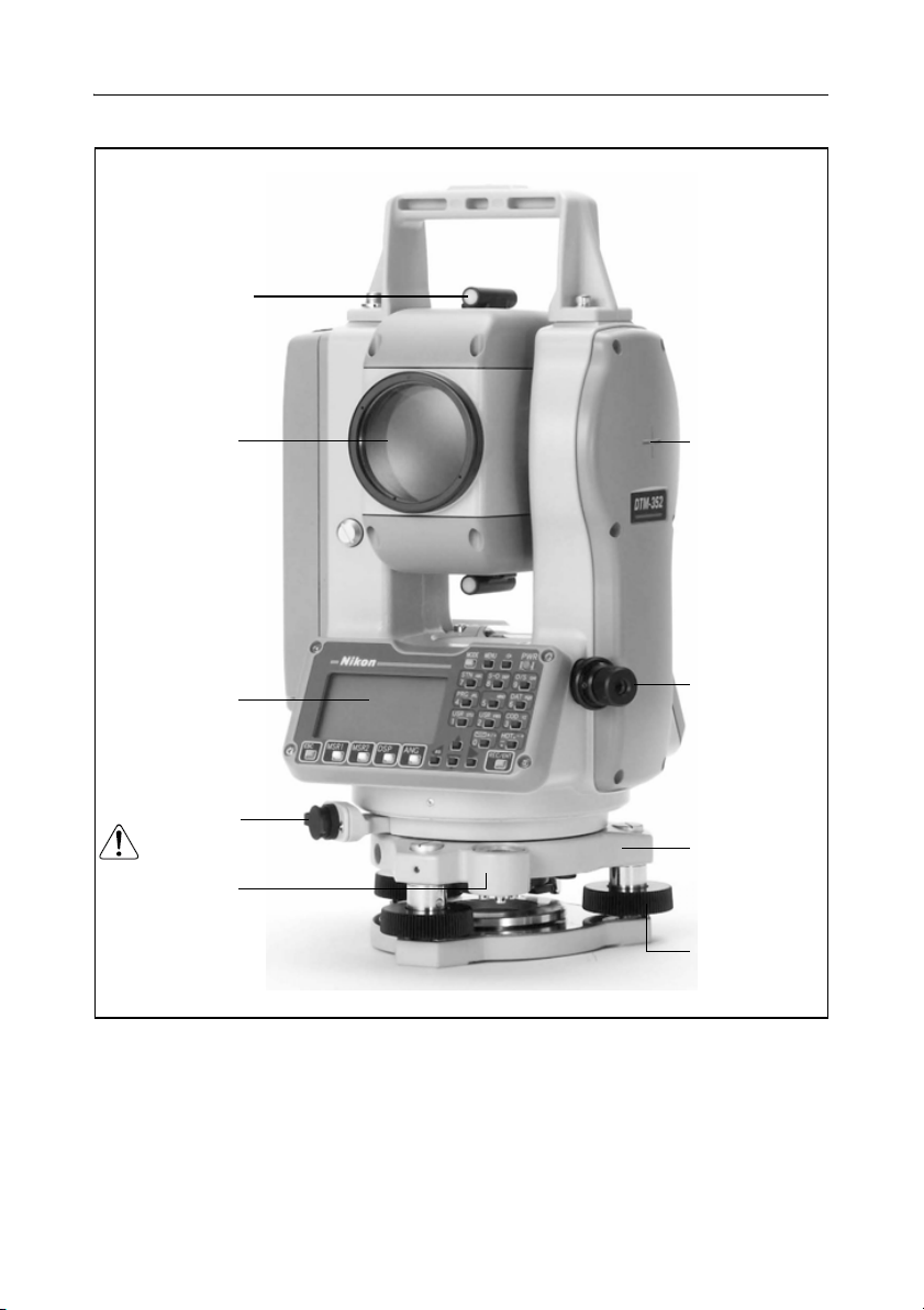
Parts of the Instrument 1.2
Figure 1.1 and Figure 1.2 show the main parts of the DTM-302 series instrument.
Carrying
handle
Telescope
focusing ring
Telescope
eyepiece
Diopter ring
Plate level
Display
and face-1
keyboard
Battery mounting
button
Vertical tangent
screw
Vertical clamp
Upper plate clamp
Upper plate
tangent screw
Leveling base
clamp knob
Figure 1.1 Electronic Total Station DTM-302 series – Face-1
4 Total Station DTM-302 Series Instruction Manual
Page 25
Optical sight
(finder)
Introduction 1
Objective
Display and
face-2 keyboard
Data output/
external power
input connector
(Input voltage
7.2 – 11 V DC)
Circular level
Figure 1.2 Electronic Total Station DTM-302 series – Face-2
Horizontal axis
indication mark
Optical plummet
Leveling base
Leveling screw
Total Station DTM-302 Series Instruction Manual 5
Page 26

1 Introduction
Maintenance 1.3
Before using the instrument, read and follow the following maintenance
instructions:
• Do not leave the instrument in direct sunlight or in a closed vehicle for
prolonged periods. Overheating the instrument may reduce its efficiency.
• If the DTM-302 series instrument has been used in wet conditions, immediately
wipe off any moisture and dry the instrument completely before returning the
instrument to the carrying case. The instrument contains sensitive electronic
assemblies which have been well protected against dust and moisture. However,
if dust or moisture gets into the instrument, severe damage could result.
• Sudden changes in temperature may cloud the lenses and drastically reduce the
measurable distance, or cause an electrical system failure. If there has been a
sudden change in temperature, leave the instrument in a closed carrying case in a
warm location until the temperature of the instrument returns to room
temperature.
• Do not store the DTM-302 series instrument in hot or humid locations. In
particular, you must store the battery pack in a dry location at a temperature of
less than 30 °C (86 °F). High temperature or excessive humidity can cause mold
to grow on the lenses. It can also cause the electronic assemblies to deteriorate,
and so lead to instrument failure.
• Store the battery pack with the battery discharged.
• When storing the instrument in areas subject to extremely low temperatures,
leave the carrying case open.
• Do not overtighten any of the clamp screws.
• When adjusting the vertical tangent screws, upper plate tangent screws, or
leveling screws, stay as close as possible to the center of each screw’s range. The
center is indicated by a line on the screw. For final adjustment of tangent screws,
rotate the screw clockwise.
• If the leveling base will not be used for an extended period, lock down the
leveling base clamp knob and tighten its safety screw.
• Do not use organic solvents (such as ether or paint thinner) to clean the
non-metallic parts of the instrument (such as the keyboard) or the painted or
printed surfaces. Doing so could result in discoloration of the surface, or in
peeling of printed characters. Clean these parts only with a soft cloth or a tissue,
lightly moistened with water or a mild detergent.
6 Total Station DTM-302 Series Instruction Manual
Page 27
Introduction 1
• To clean the optical lenses, lightly wipe them with a soft cloth or a lens tissue
that is moistened with alcohol.
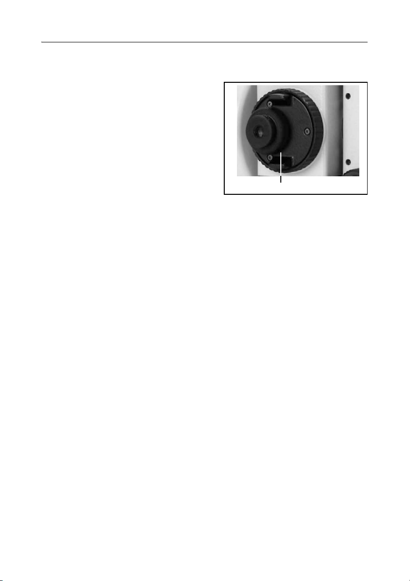
• The reticle plate cover has been correctly
mounted. Do not release it or subject it to
excessive force to make it watertight.
• Before attaching the battery pack, check
that the contact surfaces on the battery
and instrument are clean. Press the
battery pack into place until the batterymounting button rises up to the battery
pack top surface. If the battery pack is not
Reticle plate cover
attached securely, the instrument is not
watertight.
• Press the cap that covers the data output/external power input connector terminal
until it clicks into place. The instrument is not watertight if the cap is not
attached securely, or when the data output/external power input connector is
used.
• The carrying case is designed to be watertight, but you should not leave it
exposed to rain for an extended period. If exposure to rain is unavoidable, make
sure that the carrying case is placed with the Nikon nameplate facing upward.
• The BC-65 battery pack contains a Ni-MH battery. When disposing of the
battery pack, follow the laws or rules of your municipal waste system.
• The instrument can be damaged by static electricity from the human body
discharged through the data output/external power input connector. Before
handling the instrument, touch any other conductive material once to remove
static electricity.
Total Station DTM-302 Series Instruction Manual 7
Page 28

1 Introduction
8 Total Station DTM-302 Series Instruction Manual
Page 29

CHAPTER
2
Preparation 2
In this chapter:
Q Unpacking and Packing the Instrument
Q Charging and Discharging the Battery Pack
Q Detaching and Re-Attaching the Battery Pack
Q Setting Up the Tripod
Q Centering
Q Leveling
Q Sighting
Q Setting Up the Prism Reflector
Q Face-1/Face-2 Measurements
Total Station DTM-302 Series Instruction Manual 9
Page 30
2 Preparation
Unpacking and Packing the Instrument 2.1
Note – Handle the DTM-302 instrument gently to protect it from shocks and
excessive vibration.
Unpacking 21.1
To unpack the instrument, grip the carrying
handle and gently remove the instrument
from the carrying case.
Packing 21.2
Note – Store the instrument with the battery
pack attached.
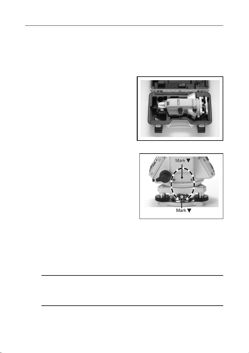
To pack the instrument back into the carrying
case:
1. Set the telescope in the horizontal face-1 position.
2. Align the W storage mark on the bottom of
the face-1 keyboard with W the mark on the
leveling base clamp knob.
3. Lightly fasten the clamp knobs.
4. Place the instrument in the carrying case.
Note – When packing the charger (Q-75U/E) in
the plastic carrying case, make sure that you
store it as shown on the sticker inside the case.
Make sure that the battery charger cable is not
pinched when you close the case cover.
Charging and Discharging the Battery Pack 2.1
Before charging the battery pack, read the warnings (also listed in the Safety section
at the front of this manual) and the following notes.
Warning – Use only the specified battery charger (part number Q-75U/E) to
C
charge the battery pack (part number BC-65). Using other chargers, such as
a charger with part number Q-7U/E or Q7C, may cause the battery pack to
catch fire or rupture.
10 Total Station DTM-302 Series Instruction Manual
Page 31

Warning – Do not cover the battery charger while the battery pack is being
C
recharged. The charger must be able to dissipate heat adequately. Coverings
such as blankets or clothing can cause the charger to overheat.
Warning – Avoid recharging the battery pack in humid or dusty places, in
C
direct sunlight, or near heat sources. Do not recharge the battery pack when it
is wet. If you do, you may receive electric shocks or burns, or the battery pack
may overheat or catch fire.
Warning – Although the battery pack (part number BC-65) has an auto-reset
C
circuit breaker, you should take care not to short circuit the contacts. Short
circuits can cause the battery pack to catch fire or burn you.
Warning – Never burn or heat the battery. Doing so may cause the battery to
C
leak or rupture. A leaking or ruptured battery can cause serious injury.
Warning – Before storing the battery pack or battery charger, cover the
C
contact points with insulation tape. If you do not cover the contact points, the
battery pack or charger may short circuit, causing fire, burns, or damage to
the instrument.
Preparation 2
Warning – The battery BC-65 is not waterproof on its own. Do not get the
C
battery wet when it is removed from the instrument. If water seeps into the
battery, it may cause a fire or burns.
Caution – Before charging the battery pack, read the instruction manual for
C
the quick charger (part number Q-75U/E).
Important notes
• Charge the battery pack indoors where the ambient temperature is between
0 °C and 40 °C (between 32 °F and 104 °F). If you try to charge the battery
when the ambient temperature is outside this range, the protective circuit will
work and prevent it from being charged normally.
Total Station DTM-302 Series Instruction Manual 11
Page 32

2 Preparation
• To prevent malfunction, keep the charging plug clean.
• If the CHARGE indicator blinks repeatedly after charging starts, there is a
problem with the battery pack. Do not use or charge the battery pack any further,
and contact your dealer.
• If the ambient temperature drops below 0 °C (32 °F) while the battery pack is
charging, the charger stops charging the battery pack. When the ambient
temperature rises above 0 °C (32 °F), charging resumes. Charging will be
completed within three hours from restarting.
• If the CHARGE indicator remains lit for more than four hours, and the ambient
temperature during charging was within the specified operational range
(0 °C through 40 °C or 32 °F through 104 °F), there is a problem with the
battery pack. Do not use or charge the battery pack any further, and contact your
dealer.
• During charging or discharging, the battery pack and quick charger will become
warm. This is normal.
• After charging the battery pack, do not recharge it until it has been fully
discharged. Recharging a fully charged battery pack lowers its performance.
• If the battery pack is used at low temperatures (below –20 °C or –4 °F), its
capacity is reduced, and it will allow less operation time than a battery pack used
at normal (room) temperature.
• If a battery pack is not used for a long period, it cannot be charged to its full
capacity again. To improve the battery pack’s capacity, charge and discharge it
several times.
• You can use a battery charger with part number Q-70U/E or Q-70C to charge a
battery pack with part number BC-65. However, these chargers cannot fully
charge this battery pack.
Charging the battery pack
Connect the power plug on the charger to
1.
an AC power outlet.
2. Connect the charging plug on the charger
cable to the charging connector on the
battery pack.
The CHARGE indicator lights up, and
charging starts automatically.
When the battery pack is fully charged, the
CHARGE indicator turns off.
12 Total Station DTM-302 Series Instruction Manual
To AC outlet
Air holes
CHARGE
indicator
DISCHARGE
indicator
DISCHARGE
button
Page 33

Preparation 2
Discharging the battery pack
1.
Connect the power plug on the charger to an AC power outlet.
2. Connect the charging plug on the charger cable to the charging connector on the
battery pack.
3. Press the DISCHARGE button on the battery charger.
The DISCHARGE indicator lights up, and the charger starts to discharge the
battery. When discharging is completed, the DISCHARGE indicator turns off.
Then the CHARGE indicator lights up, and charging starts automatically.
To stop discharging the battery pack, press the DISCHARGE button again.
Note – The battery pack can be recharged repeatedly. If you recharge the battery
pack while it still has enough power to operate the instrument, however, it will last
for a shorter period. This is called the memory effect. If you experience the memory
effect, discharge the battery pack as described above and then recharge it. This
returns the battery pack to its full capacity. We recommend that you discharge the
battery pack in this way at least once every ten charges.
Detaching and Re-Attaching the Battery Pack 2.1
Detaching the BC-65 battery pack
If the instrument is turned on, press [PWR] to turn it off.
1.
2. Depress the battery mounting button while holding the battery pack.
Caution – Avoid touching the contacts on the battery pack.
C
Total Station DTM-302 Series Instruction Manual 13
Page 34

2 Preparation
Attaching the BC-65 battery pack
Before you attach the battery pack, clear any dust or other foreign particles from the
battery socket.
1. Fit the two projections at the bottom of
the battery pack into the concave sections
at the bottom of the socket on the
instrument.
2. Hold the instrument steady with one hand
and push the battery pack against the
instrument.
3. Make sure that the battery mounting
button is securely locked.
Caution – If the battery pack is not attached securely, this could adversely
C
affect the watertightness of the instrument.
Note – An external battery is available as an optional accessory for DTM-302
instruments. When the external battery is connected and the BC-65 battery pack is
mounted on the instrument, the instrument automatically uses the power source that
has the most available power.
1
4
3
2
Setting Up the Tripod 2.1
Caution – The tops of the tripod ferrules are very sharp. When handling or
C
carrying the tripod, take care to avoid injuring yourself on the ferrules.
Open the tripod legs enough to for the instrument to be stable.
1.
2. Locate the tripod directly over the station point. To check the tripod’s position,
look through the center hole in the tripod head.
3. Firmly press the tripod ferrules into the ground.
4. Level the top surface of the tripod head.
Note – If you want to use the plumb bob to center the instrument (see Centering,
page 15), you must level the tripod head precisely.
5. Securely fasten the thumb screws on the tripod legs.
6. Place the instrument on the tripod head.
14 Total Station DTM-302 Series Instruction Manual
Page 35

Preparation 2
7.
Insert the tripod mounting screw into the center hole of the base plate of the
instrument.
8. Tighten the tripod mounting screw.
Note – Do not carry the instrument while it is attached to a tripod.
Centering 2.1
When you center the instrument, you align its central axis precisely over the station
point. To center the instrument, you can either use the optical plummet or a plumb
bob.
Centering using the optical plummet 21.1
Note – If you require high accuracy, check and adjust the optical plummet before
you center the instrument. For detailed instructions, see Checking and Adjusting the
Optical Plummet, page 167.
To center the instrument using the optical plummet:
1. Set up the instrument on the tripod. For detailed instructions, see Setting Up the
Tripod, page 14.
2. While looking through the optical plummet, align
the reticle with the station point. To do this, turn
the leveling screws until the center mark of the
reticle is directly over the image of the station
point.
3. While supporting the tripod head with one hand,
loosen the tripod leg clamps and adjust the lengths
of the legs until the air bubble is in the center of
the circular level.
4. Tighten the tripod leg clamps.
5. Use the plate level to level the instrument. For detailed instructions, see
Leveling, page 16.
6. Look through the optical plummet to check that the image of the station point is
still in the center of the reticle mark.
7. If the station point is off center, do one of the following:
– If the station point is slightly off center, loosen the tripod mounting screw
and then center the instrument on the tripod. Use only direct movement to
center the instrument. Do not rotate it.
Total Station DTM-302 Series Instruction Manual 15
Page 36

2 Preparation
When the instrument is centered, tighten the mounting screw.
– If the displacement of the station point is major, repeat this procedure from
Step 2.
Centering using a plumb bob 20.1
1. Set up the instrument on the tripod. For detailed instructions, see Setting Up the
Tripod, page 14.
2. Hang the plumb line on the hook of the tripod mounting screw.
3. Adjust the length of the plumb line so that the tip of the plumb bob is at the
height of the station point.
4. Loosen the tripod mounting screw slightly.
5. Using both hands to support the outer side of the leveling base, carefully slide
the instrument about on the tripod head until the tip of the plumb bob is
positioned over the exact center of the station point.
Note – To confirm that the instrument is precisely aligned, check its position
from two directions at right angles to each other.
Leveling 2.1
When you level the instrument, you make the vertical axis of the instrument exactly
vertical. To level the instrument, use the plate level.
To level the instrument:
1. Loosen the upper plate clamp.
2. Rotate the alidade until the plate level is
parallel with any two of the leveling screws
(B and C).
3. Use leveling screws B and C to move the
bubble into the center of the level.
4. Rotate the alidade approximately 90°.
A
CB
16 Total Station DTM-302 Series Instruction Manual
1
Page 37

Preparation 2
5.
Use leveling screw A to move the bubble
into the center of the level.
6. Repeat Step 1 through Step 5 to center the
bubble in both positions.
7. Rotate the alidade 180°.
8. If the bubble in the plate level remains
centered, the instrument is level. If the
bubble moves off center, adjust the plate
A
CB
2
level. For detailed instructions, see
Checking and Adjusting the Plate Level, page 166.
Sighting 2.1
When you sight the instrument, you aim the
telescope at the target, bring the target image
into focus, and align the image with the center
crosshairs of the reticle.
To sight the instrument:
1. Adjust the diopter:
a. Aim the telescope at a blank area, such
as the sky or a piece of paper.
Center
crosshairs
Warning – Never look at the sun through the telescope. If you do, you may
C
damage or lose your eyesight.
b.
Looking through the eyepiece, rotate
the diopter ring until the reticle
crosshairs are in sharp focus.
2. Eliminate parallax:
a. Aim the telescope at the target image.
b. Rotate the focusing ring until the
target image is in sharp focus on the
reticle crosshairs.
c. Move your eye vertically and laterally
Diopter ring
Telescope focusing
ring
to check whether the target image
moves relative to the reticle crosshairs.
If the target image does not move, there is no parallax.
Total Station DTM-302 Series Instruction Manual 17
Page 38

2 Preparation
d.
If the target image does move, rotate the telescope focusing ring. Then repeat
from Step c.
Setting Up the Prism Reflector 2.1
1. Assemble the prism reflector as shown in Figure 2.1.
Target plate for single prism
Tribrach adapter 13/14
Target pole
Leveling base
Tiltable single
prism holder
Tr i po d
Figure 2.1 Assembling the prism reflector
2. Adjust the height of the tribrach adaptor (see page 19).
3. If necessary, change the direction of the prism (see page 19).
4. Set the prism constant (see page 19).
5. If you are using a single prism holder, set the position of the target plate (see
Prism C
Triple prism holder
page 20).
Detailed instructions for Step 2 through Step 5 are provided on the following pages.
18 Total Station DTM-302 Series Instruction Manual
Page 39

Preparation 2
Adjusting the height of the tribrach adapter 20.1
The tribrach adapter has two height settings. To use the prism reflector with a
DTM-302 series instrument, use the lower height setting.
To adjust the height of the tribrach adapter:
1. Remove the height adjustment screw from
the tribrach adapter.
2. Slide the tribrach adapter up or down the
Prism holder mount
prism holder mount until the height
adjustment screw holes on the prism holder
mount and on the tribrach adapter are
Height adjustment
screw
aligned.
3. Replace and tighten the adjustment screw.
Changing the direction of the prism 20.1
The prism mounted on the tribrach adapter can be rotated to face in any direction.
To change the direction of the prism:
1. Release the rotation clamp. To do this, turn
the clamp lever counterclockwise.
2. Turn the upper plate of the tribrach adapter
until the prism is facing in the required
direction.
3. Fasten the rotation clamp. To do this, turn
the clamp lever clockwise.
Clamp
Clamp lever
Unclamp
Setting the prism constant 20.1
1. Attach the prism to the single prism holder or triple prism holder.
Tip – To use a triple prism holder as a single prism holder, attach the prism to
B
the center thread of the prism holder.
Total Station DTM-302 Series Instruction Manual 19
Page 40

2 Preparation
2.
Set the prism constant. To do this, hold down
[MSR1] or [MSR2] for one second. For more
information, see Measurement settings,
page 56.
Note – The prism constant of a Nikon prism is
always 0, whether it is attached to a single
prism holder or a triple prism holder.
If your prism constant is not 0mm, then directly enter the prism constant value
in the Const field. For example, if your prism constant is 30mm, enter 30mm in the
Const field on the instrument.
Setting the position of the target plate 20.1
If using a single prism, make sure that the target plate is aligned with the tribrach
adapter and the prism.
To set the position of the target plate:
1. Use the two set screws supplied to attach
the target plate to the single prism holder.
2. Move the target plate within the screw
holes until the apex of the wedge pattern is
aligned with the vertical axis of the prism
and the tribrach adapter.
Center on axis
Face-1/Face-2 Measurements 2.1
You can take a measurement from either face of the instrument. To change the face,
rotate the instrument 180° on its base, and rotate the telescope 180° within the
standard.
By averaging the Face-1 and Face-2 measurement values, you can cancel out most
constant mechanical errors. Some errors, such as vertical axis error, cannot be
cancelled out by averaging Face-1 and Face-2 measurements.
Caution – When rotating the telescope, take care not to catch your finger in
C
the gap between the instrument’s standard and the telescope.
20 Total Station DTM-302 Series Instruction Manual
Page 41

Preparation 2
A Face-1 measurement is made with the vertical circle positioned to the left of the
telescope eyepiece. A Face-2 measurement is made with the vertical circle
positioned to the right of the telescope eyepiece. See Figure 2.2.
Face- 1 Face-2
Figure 2.2 Face-1 and Face-2
Total Station DTM-302 Series Instruction Manual 21
Page 42

2 Preparation
22 Total Station DTM-302 Series Instruction Manual
Page 43

CHAPTER
3
Getting Started 3
In this chapter:
Q Turning the Instrument On and Off
Q Selecting a Language
Q Changing Regional Configuration Pre-sets
Q Display and Key Functions
Q List Display
Q Inputting Data
Q Jobs
Q Measuring Distances
Total Station DTM-302 Series Instruction Manual 23
Page 44
3 Getting Started
Turning the Instrument On and Off 3.1
Turning on the instrument 31.1
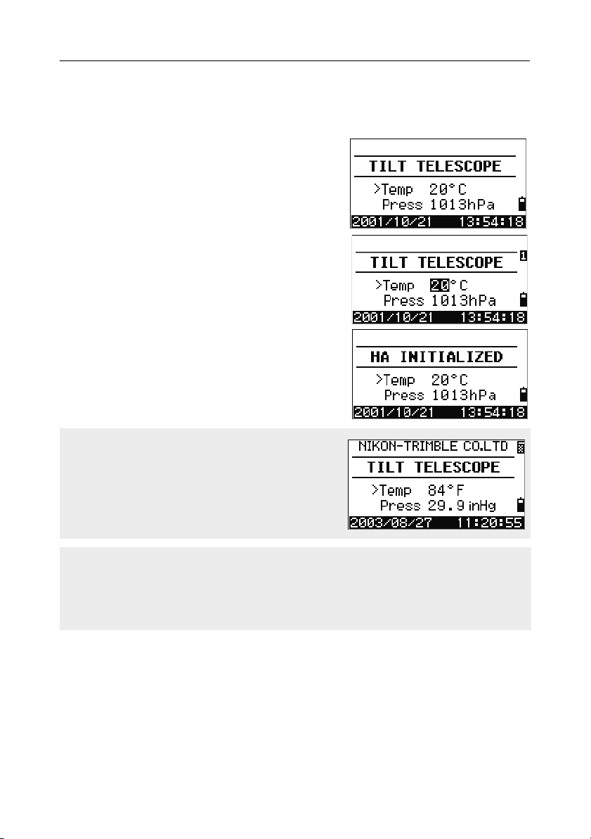
1. To turn on the instrument, press [PWR]. The
start-up screen appears. It shows the current
temperature, pressure, date, and time.
2. To change the temperature or pressure value,
use
[^] or [v] to move the cursor to the field that
you want to change. Then press
3. If you want to initialize the horizontal angle,
rotate the alidade.
4. Tilt the telescope until it passes the horizontal
position on Face-1.
If you have entered your name or your company’s
name in the Owner’s detail field, the text from this
field appears on the start-up screen. To set the
Owner’s detail field, go to MENU > Settings
> Other
. For more information, see page 136.
[ENT].
Once you start to use an initialized HA, you must rotate the alidade to initialize the
HA every time you turn on the instrument. If you do this, you can maintain a fixed HA
orientation even if the instrument has moved while it is turned off.
If you tilt the telescope before you rotate the alidade, the horizontal angle is not
initialized, and the instrument uses the previous HA reading.
24 Total Station DTM-302 Series Instruction Manual
Page 45

Getting Started 3
Turning off the instrument 30.1
To turn the instrument off, press [PWR] and [ENT].
Then do one of the following:
Press ... To ...
[ENT] again turn off the instrument
Reset softkey reboot the program and re-start the instrument
the
Sleep softkey put the instrument into power-saving mode
the
[ESC] cancel the power-off process and return to the
previous screen
If you press the Reset softkey, the software is rebooted and the Basic
Measurement Screen (BMS) appears without an open job.
Sleep mode
If you press the Sleep softkey in the Press [ENT]
→ OFF screen, or enable the Power Save setting
(see Power saving, page 134), the instrument goes
into sleep mode.
When the instrument is in sleep mode, it wakes up
if any of the following occurs:
• You press a key
• The instrument receives a remote control command
• You rotate the alidade
• You tilt the telescope
Total Station DTM-302 Series Instruction Manual 25
Page 46
3 Getting Started
Selecting a Language 3.1
The Nikon total station supports one Language Pack at a time. The Language Pack
is a set of up to three different languages installed on the instrument from which the
user can select. Several Language Packs are available for the Nikon total stations.
• Language Pack #1: English, French, Spanish
• Language Pack #2: English, German, Italian
• Language Pack #3: English, Chinese, Russian
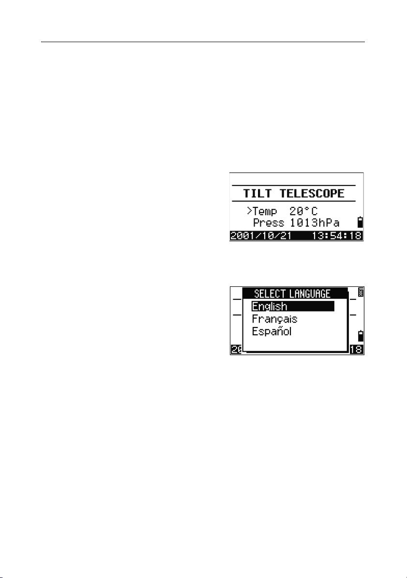
1. To select a different language, power on
the instrument and press
Tilt Telescope screen.
The Select Language screen appears. Up to
three languages are available in the
installed Language Pack. The screen shows
which languages are currently available on
the instrument.
The current language selection is highlighted.
2. Press [^] or [v] to highlight the required
language and then press
3. The instrument reboots and displays the
start-up Tilt Telescope screen in the
selected language.
[ESC] and [3] at the
[ENT.]
Language Pack #1 is the default Language Pack installed at the factory. Other
Language Packs can be installed at an authorized Nikon total station service
provider.
26 Total Station DTM-302 Series Instruction Manual
Page 47
Getting Started 3
Changing Regional Configuration Pre-sets 3.1
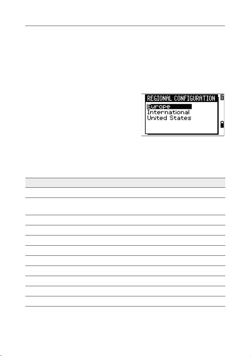
To provide easier configuration for common regional settings, you can quickly
configure the Nikon total station to a pre-set combination of default regional
settings. The Regional Configuration screen appears only after the language
configuration is complete, the instrument has rebooted, and the telescope has been
tilted. To change the regional configuration pre-sets:
1. Follow the steps in Selecting a Language, page 26 .
Once the instrument reboots and the
telescope is tilted, the Regional
Configuration screen appears.
2. Press [^] or [v] to highlight the required
regional settings and then press
3. If you do not want to change the current
settings, press
[ESC] and quit. The
instrument will continue to use the last settings that were configured.
The settings affected by the Regional Configuration screen are:
Table 3.1 Regional Configuration Pre-sets
Category Setting Europe International United States
Angle
VA zero Zenith Zenith Zenith
[ENT].
Distance
Coordinates
Resolution 1" 1" 1"
HA Azimuth Azimuth Azimuth
Scale 1.000000 1.000000 1.000000
T-P corr. On On On
Sea Level Off Off Off
C&R corr. 0.132 0.132 0.132
Order ENZ ENZ NEZ
Label ENZ ENZ NEZ
Total Station DTM-302 Series Instruction Manual 27
Page 48

3 Getting Started
Table 3.1 Regional Configuration Pre-sets
Category Setting Europe International United States
AZ zero North North North
Power Save
Main Unit Off Off Off
EDM Unit 3 minutes 3 minutes 3 minutes
Sleep 5 minutes 5 minutes 5 minutes
Communication
Ext. Comm Nikon Nikon Nikon
Baud 4800 4800 4800
Length 8 8 8
Parity None None None
Stop bit 1 1 1
Stakeout
Add PT 1000 1000 1000
Units
Angle GON GON DEG
Distance meters meters US-ft
Temp ° C ° C ° F
Press mm Hg mm Hg In Hg
Rec
Store DB RAW&XYZ RAW&XYZ RAW&XYZ
Data Rec Internal Internal Internal
Others
XYZ disp Fast Fast Fast
2nd Unit None None None
Sig Beep On On On
Split ST No No No
28 Total Station DTM-302 Series Instruction Manual
Page 49

Getting Started 3
Table 3.1 Regional Configuration Pre-sets
Category Setting Europe International United States
CD Input <ABC> <ABC> <ABC>
Owner’s
Detail
Blank Blank Blank
The default regional configuration pre-set is “United States” settings. For more
information, see Settings, page 131.
Display and Key Functions 3.1
Figure 3.1 shows the keys on the DTM-302 series instrument keyboard and the
LCD display.
Figure 3.1 DTM-302 keyboard and display
Total Station DTM-302 Series Instruction Manual 29
Page 50

3 Getting Started
Table 3.2 summarizes the functions of the DTM-302 keys.
Table 3.2 Key functions
Key Function Details
Turns the instrument on or off. page 24
Illumination key. Turns the backlight on or off.
Provides access to the 2-switch window if held down for
one second.
Displays the MENU screen. page 111
Changes the key input mode between alphanumeric
and numeric if pressed when you are in a PT or CD
field.
Activates Qcode mode if pressed when you are In the
Basic Measurement Screen (BMS).
Records measured data, moves on to the next screen,
or confirms and accepts the entered data in input mode.
You have the option to record the measurement as a CP
record instead of an SS record, if you hold this key down
for one second in the Basic Measurement Screen
(BMS).
The instrument outputs the current measurement data
(PT, HA, VA, and SD) on the COM port if you press this
key in the BMS or in a Stakeout observation screen.
(The Data Rec settings must be set to COM.)
Returns to the previous screen.
In numeric or alphanumeric mode, deletes input.
page 34
page 37
page 99
Starts distance measurement, using the measure mode
settings for the [MSR1] key.
Displays measurement mode settings, if held down for
one second.
30 Total Station DTM-302 Series Instruction Manual
page 54
Page 51

Getting Started 3
Table 3.2 Key functions (continued)
Key Function Details
Starts distance measurement, using the measure mode
settings for the [MSR2] key.
Displays measurement mode settings, if held down for
one second.
Moves to the next available display screen.
Changes the fields that appear on the DSP1, DSP2,
and DSP3 screens, if held down for one second.
Displays the Angle menu. page 60
Displays the Station Setup menu.
In numeric mode, enters 7. In alphanumeric mode,
enters A, B, C, or 7.
Displays the Stakeout menu.
Shows stakeout settings, if held down for one second.
In numeric mode, enters 8. In alphanumeric mode,
enters D, E, F, or 8.
Displays the Offset Point Measurement menu.
In numeric mode, enters 9. In alphanumeric mode,
enters G, H, I, or 9.
Displays the Programs menu, which contains additional
measuring programs.
In numeric mode, enters 4. In alphanumeric mode,
enters J, K, L, or 4.
In numeric mode, enters 5. In alphanumeric mode,
enters M, N, O, or 5.
page 54
page 57
page 62
page 77
page 101
page 86
Displays RAW, XYZ, or STN data, depending on your
setting.
In numeric mode, enters 6. In alphanumeric mode,
enters P, Q, R, or 6.
Total Station DTM-302 Series Instruction Manual 31
page 43
Page 52

3 Getting Started
Table 3.2 Key functions (continued)
Key Function Details
Executes the function that is assigned to the [USR1] key.
In numeric mode, enters 1. In alphanumeric mode,
enters S, T, U, or 1.
Executes the function that is assigned to the [USR2] key.
In numeric mode, enters 2. In alphanumeric mode,
enters V, W, X, or 2.
Opens a window where you can enter a code. The
default code value is the last code entered.
In numeric mode, enters 3. In alphanumeric mode,
enters Y, Z, a space, or 3.
Displays the (HOT) menu, which includes Height of
Target, Temp-Press, Target, Note recording, and Default
PT settings.
In numeric mode, enters – (minus). In alphanumeric
mode, enters . (period), – (minus), or + (plus).
Displays the Bubble indicator.
In numeric mode, enters 0. In alphanumeric mode,
enters *, /, =, or 0.
page 42
page 38
page 39
page 41
Status bar 31.1
The status bar appears on the right side of
every screen. It contains icons that indicate
the status of various system functions.
Status bar
Signal indicator
The signal indicator shows the reflected light intensity:
Level 4 (maximum)
Level 3
32 Total Station DTM-302 Series Instruction Manual
Page 53

Getting Started 3
Level 2
Level 1 (minimum)
If this icon is blinking, the signal is flickering.
If this icon is blinking rapidly, the signal is low.
If this icon is blinking slowly, there is no signal.
If there is no icon, analog power for EDM is off.
Input mode indicator
The Input mode indicator only appears when you are entering points or coordinates.
It shows the data input mode:
Input mode is numeric. Press a key on the number pad to enter the
number printed on the key.
Input mode is alphabetic. Press a key on the number pad to enter the first
letter printed beside the key. Press the key repeatedly to cycle through all
the letters assigned to that key.
For example, to enter the letter O in alphabetic mode, press [5] three times.
Battery indicator
The battery indicator shows the battery voltage level:
Level 4 (Full)
Level 3
Level 2
Level 1
Battery low
If the battery level is critically low, the following
message appears:
Total Station DTM-302 Series Instruction Manual 33
Page 54

3 Getting Started
Adjusting lighting and sound levels 31.2
LCD backlight
To turn the LCD backlight on or off, press the illumination key . To adjust the
backlight level, use the 2-switch window described below.
2-switch window
Use the 2-switch window to adjust lighting and
sound settings for the instrument.
To open the 2-switch window from any screen,
hold down the Illumination key for one second.
To cycle through the settings for a switch, press
the number beside that switch. For example, to
turn the backlight on or off, press
Alternatively, to highlight the switch that you want to set, press
[ENT] to cycle through the settings for that switch.
Switch 1 (backlight)
LCD backlight is on.
LCD backlight is off.
[1].
[^] or [v]. Then press
Switch 2 (Sound)
Sound is on.
Sound is off.
Contrast adjustment window
When the 2-switch window is open, press [<] or [>]
to display the contrast adjustment window. Then
press
[^] or [v] to change the contrast level. The
arrow indicates the current contrast level. To
return to the 2-switch window, press
[<] or [>].
When you have finished changing display light
and sound settings, press
[ESC] to close the
2-switch or contrast adjustment window.
34 Total Station DTM-302 Series Instruction Manual
Page 55

Getting Started 3
[DSP]
key 31.3
Use the key to change the current display screen or to change display settings.
Switching between display screens
When several display screens are available, the
DSP indicator appears at the top left of the screen,
and the screen indicator (for example,
1/4)
appears at the top right.
To move to the next available screen, press
[DSP].
For example, if the DSP2 screen is currently
displayed, press
The screen indicator changes from
When the secondary distance unit is set, an
additional screen is available. It shows the HD,
VD, and SD values. For information on setting the
secondary distance unit, see page 136.
The smallest unit of display for distances
measured in feet-and-inches is 1/16 in. Smaller
units are impractical in the field. When the actual
value is greater than 99999'11''15/16, the “>”
symbol is shown. If the actual distance is less than -9999'11''15/16, the “`” (solid
triangle) symbol is shown. This does not affect calculations. The precise value is
used internally in all cases.
[DSP] to move to the DSP3 screen.
2/4 to 3/4.
Total Station DTM-302 Series Instruction Manual 35
Page 56

3 Getting Started
Customizing items in the Basic Measurement Screen (BMS)
To customize the items that are displayed on the DSP1, DSP2, and DSP3 screens:
1. Hold down [DSP] for one second.
2. Use the arrow keys [^], [v], [<], and [>] to
highlight the item that you want to change.
3. Use the and softkeys to scroll through the
list of items that can be displayed for this item.
The items that you can choose from are HA,
AZ, HL, VA, V%, SD, VD, HD, Z, and (none).
4. To save your changes, press the Save softkey. Alternatively, highlight the last
item for DSP3 and press
[ENT]. The DSP screens show the items you have
selected.
Except for the (none) item, you cannot display the same item on more than one line
of the same screen.
The items displayed in the DSP1, DSP2, DSP3, and DSP4 screens are also used in
the corresponding Stakeout screens (SO2, SO3, SO4, and SO5).
You can also customize the displayed items in Stakeout.
Header characters
The following header characters can be used in DSP screens:
A colon (:) indicates that tilt correction is applied
to the value.
A hash symbol (#) indicates that tilt correction is
off.
An underscore (_) under the tilt correction
character indicates that Sea Level Correction or
Scale factor is applied.
36 Total Station DTM-302 Series Instruction Manual
Page 57

Getting Started 3
[MODE] key 30.1
Use the [MODE] key to change the keyboard mode for the current screen.
Changing input mode while entering points or codes
When the cursor is in a point (PT) or code (CD)
field, press
between alphanumeric (
The input mode indicator in the status bar changes
to show the current input mode.
When the cursor is in a height (HT) field, only numeric input mode is available.
Pressing [MODE] has no effect when the cursor is in a HT field.
Quick code measurement mode
To activate Quick code measurement mode,
1.
press
[MODE] to change the input mode
A) and numeric (1).
[MODE] in the BMS.
The PT field shows the default point name.
2. Press any numeric key ([0] through [9]) to start
measuring and recording points.
A list of the numeric keys and their assigned
feature codes appears on the right side of the
screen.
For example, when you press
[6], the code
assigned to 6 is selected, and the instrument
starts a measurement.
Total Station DTM-302 Series Instruction Manual 37
Page 58

3 Getting Started
3.
If you have set the record mode to Confirm
(see Measurement settings, page 56), the
Record PT screen appears after each
measurement.
Do one of the following:
– To record the point, press
– To return to the BMS, press
To assign a new feature code to a numeric key, press [^] or [v] to highlight the code
that you want to change. Then press the Edit softkey.
You can use the DSP softkey to change the values shown in the measurement box,
in the same way as you use the [DSP] key in the Basic Measurement Screen (BMS).
4. To return to the BMS from the Qcode screen, press [MODE] or [ESC].
[ENT].
[ESC].
[COD] key 30.1
In the BMS, press [COD] to change the default feature code that will appear in the CD
field when you record a point.
Setting the default code
When you press [COD] in the BMS, a window for
entering the feature code appears.
You can use the
enter the code.
List and Stack softkeys to
Qcode observations
To enter the Quick code observation routine, press
the
Qcode softkey.
In this function, you can use the ten numeric keys
to both select a feature code and shoot a point.
To change the measurement mode for the Quick
code observation, press the
38 Total Station DTM-302 Series Instruction Manual
Sett softkey.
Page 59

Getting Started 3
In Quick code measurement, the Rec mode can only be set to Confirm or ALL.
[HOT] key 30.2
The HOT key menu is available on any
observation screen. To display the HOT key menu,
press
[HOT].
Changing the height of the target
To change the height of the target, press [HOT] to
display the HOT menu. Then either press
select
HT and press [ENT].
Enter the height of the target, or press the
softkey to display the HT stack. The HT stack
stores the last 20 HT values entered.
Setting the temperature and pressure
To set the current temperature and pressure, press
[HOT] to display the HOT menu. Then either press
[2] or select Temp-Press and press [ENT]. Enter
the ambient temperature and pressure. The ppm
value is updated automatically.
[1] or
Stack
Selecting the target set
A target set specifies settings for the target type,
the prism constant, and height of target. When you
change the selected target set, all three settings are
changed. You can use this function to quickly
switch between two types of target, such as a
reflector sheet and a prism. You can prepare up to
five target sets.
Press
[HOT] to display the HOT menu. Then either press [3], or select Target and
press
[ENT]. A list of the five target sets appears. To select a target set, either press the
corresponding numeric key (
in the list and press
[ENT].
[1] through [5]), or use [^] or [v] to highlight the target set
Total Station DTM-302 Series Instruction Manual 39
Page 60

3 Getting Started
To change the settings defined in a target set, highlight the target set in the list.
Then press the
Type Prism/Sheet
Const –999 to 999 mm
HT –9.990 to 99.990 m
HT can be left blank in the target set. If you leave it blank, the current HT value is
always applied to the measurement.
When a target set is selected, the Type and Const values are copied to both [MSR1]
and [MSR2] settings, and to the measurements in Qcode. If you have specified a
value for HT, this value is also copied to the current HT.
Entering a field note
Edit softkey.
To enter a field note, press [HOT] to display the
HOT menu. Then either press
and press
[ENT].
[4], or select Note
This function can be used at any time on any
observation screen.
Each note can be up to 50 characters.
The note is stored as a CO record in the raw data.
To display a list of previously used notes, press
the
Stack softkey. The stack stores the last 20
notes.
Use
[^] or [v] to highlight a note in the list. Then
press
[ENT] to select the note.
40 Total Station DTM-302 Series Instruction Manual
Page 61

Getting Started 3
Setting the default point name
To change the default point name, press [HOT] to
display the HOT menu. Then press
Default PT and press [ENT].
[5], or select
This function is available from any observation
screen.
Modify the default point name for the next record.
Press
[ENT] to confirm the new default point name.
The new point name is appears as the default PT
name on the input screen.
Bubble indicator 30.3
The bubble indicator is automatically displayed if the instrument goes out of level
while the compensators are turned on.
To display the bubble indicator in an observation screen, press .
The DTM-362/352 has two-axis level
compensation. To turn the leveling compensators
on or off, press
compensators are turned off, the text OFF appears
on the screen.
[<] or [>]. When the leveling
If the instrument is more than ±3'30" out of level,
the text OVER appears on the screen.
To return to the observation screen, press
[ENT] .
[ESC] or
The DTM-332 has vertical axis adjustment only.
To turn the leveling compensators on or off, press
[<] or [>].
The current setting of leveling compensators is indicated by header characters (:, #,
:, and #) after field labels (such as HA, VA, SD, and HD) in observation screens. For
more information, see Header characters, page 36.
Total Station DTM-302 Series Instruction Manual 41
Page 62

3 Getting Started
[USR] keys 30.4
If you use a function frequently in the field, you can assign it to the [USR1] or [USR2]
key. Whenever you press a
activated directly.
The following functions can be assigned to the
• Input HT
• BS Check
• Base XYZ
• Default PT
• Select Target
• Input Temp-Press
• Input Note
• The following menus, or a single function from one of these menus:
– Cogo
–O/S
–PRG
By default, Input HT is assigned to
Hold down the
[USR] key for one second to display
the list of functions that can be assigned to the
key. The currently assigned function is indicated
by an asterisk (*) beside the function name.
To change the function that assigned to the key,
press
[^] or [v] to highlight the function. Then press
[ENT].
If an item on the list has an arrow (
this item is a menu. If you highlight a menu item
and then press
[ENT], a sub-menu appears.
[USR] key, the function that is assigned to that key is
[USR] keys:
[USR1], and no function is assigned to [USR2].
->) beside it,
The first item on the sub-menu ends with the text
[MENU]. If you select this item, the whole menu
is assigned to the
42 Total Station DTM-302 Series Instruction Manual
[USR] key.
Page 63

Getting Started 3
To assign a specific function from the sub-menu, press [^] or [v] to highlight the
function. Then press
Once you have assigned a function to a
it is called directly whenever you press that
[ENT].
[USR] key,
[USR]
key in the BMS.
To change the type of data that is assigned to the
[USR] keys in MENU > 1sec-Keys > [USR].
For more information, see [USR] key settings,
page 161.
[DAT] key 30.5
Use the [DAT] key to quickly access data in the current job from observation screens.
When you press
observation screens in functions such as Stakeout,
2Pt RefLine, and Arc RefLine, the assigned data
in the current job appears.
Hold down
observation screen to display the Select Format
screen. Use this screen to change the type of data
that is assigned to
DAT [MENU] to display the Data menu
whenever you press
[DAT] in the BMS or in
[DAT] for one second in the BMS or an
[DAT]. Press [1] or select
[DAT].
Total Station DTM-302 Series Instruction Manual 43
Page 64

3 Getting Started
When you select an option from this screen, the
change is applied immediately, and the selected
data type appears.
Press
[ESC] to return to the previous observation
screen.
To change the type of data that is assigned to
[DAT], go to MENU > 1sec-Keys > [DAT].
For more information, see [DAT] key settings,
page 162.
List Display 3.1
Available jobs or data appear in a list display when you do any of the following:
• view or edit data (
• open the code list, point list, or Job Manager (
• search for points or codes
In the list, the current cursor position is shown in
reverse video (it appears as white text on a black
background).
Press
[^] or [v] move the cursor one line up or down.
If the Page Up icon appears, there are more
pages before the current page. Press
one page.
If the Page Down icon appears, there are more pages after the current page. Press
[>] to move down one page.
To select an item from the list, move the cursor onto the item and press
MENU > Data)
MENU > Job)
[<] to move up
[ENT].
44 Total Station DTM-302 Series Instruction Manual
Page 65

Getting Started 3
Inputting Data 3.2
Entering a point name or number 32.1
You can use numeric or alphanumeric names up to 16 characters long to identify
points.
The default name for a new point is the last point name entered, with the last digit
incremented. For example, if the last point name was A100, the default name for the
next point is A101.
If the last character of the previous point name is alphabetic, the default point name
is the last point name.
When the cursor is in a PT (point) field, there are several ways to specify a point, or
input coordinates.
Entering an existing point
When you enter a known point name or number,
the coordinates of that point are displayed briefly.
A short beep sounds before the next screen
appears or the next field is selected.
To adjust the duration of the coordinate window
display, go to MENU > Settings >
Others
press [ENT], set the XYZ disp field to +ENT. For
more information, see page 136.
. To leave the window open until you
Total Station DTM-302 Series Instruction Manual 45
Page 66

3 Getting Started
Entering a new point
When you input a new point name or number, a
coordinate input screen appears. Enter the point’s
coordinates in NE, NEZ, or elevation-only (Z)
format.
Press
[ENT] on the last line (the CD field) to store
the point in the current job.
Pressing [ENT] without a point name
To use a point without recording the coordinates,
press
[ENT] in a PT field, without entering a point
name.
The input coordinates are used in the calculation.
They are not saved in the database.
Specifying a wildcard (*)
If you include an asterisk (*) when you enter a
point or code name, a list of points that match the
entered text appears.
Use
[^] or [v] to move the cursor to the point that
you want to use. Then press
[ENT].
If the Page Up or Page Down icons are
displayed, use
[<] or [>] to page up or page down
the list.
46 Total Station DTM-302 Series Instruction Manual
Page 67

When you select a point from the list, its
coordinates are displayed and a beep sounds.
Recording an instant measurement
You can also input a point by recording an instant
measurement. To do this, press the
MSR softkey.
An observation screen appears.
Press
[MSR1] or [MSR2] to start a measurement. To
change the height of the target, press the
HT
softkey.
To go to the point recording screen when you have
finished the measurement, press
Enter the point or code name. Press
[ENT].
[ENT].
Getting Started 3
When you move the cursor to a field, the current
or default value appears in inverted text (this is
the default “Replace All” input mode).
Press [>] to change the input mode to Overwrite
mode and highlight the first character. Press [<] to
move the cursor the end of the string.
Total Station DTM-302 Series Instruction Manual 47
Page 68

3 Getting Started
Entering a point from the stack
The point stack is a list of recently used points. To
display the stack, press the
Stack softkey when
the cursor is in the PT field.
Use
[^] or [v] to move the cursor to the point that
you want to use. Then press
[ENT].
When you return to the point input screen, the
selected point name is entered in the PT field,
incremented by one. For example, if you selected
the A101 point, A102 appears in the PT field.
The stack shows the last 20 point names used, in chronological order from last used
to first used.
Entering a point from the point list
To display a list of existing points, press the List
softkey when the cursor is in the PT field.
Use
[^] or [v] to move the cursor to the point that
you want to use. Then press
[ENT].
When you return to the point input screen, the
selected point name is entered in the PT field. You
can add digits or alphabetic characters if required.
Entering a code 32.2
The CD (Code) field always defaults to the last code used. You can change the
selected code on the input point screen, or you can press
information, see [COD] key, page 38.
You can use numeric or alphanumeric names up to 16 characters long to identify
codes.
48 Total Station DTM-302 Series Instruction Manual
[COD] in the BMS. For more
Page 69

Entering a code directly
To enter a code directly, press [MODE] to change the
input mode to alphanumeric or numeric mode.
Then use the keypad to enter the code.
Entering a code from the stack
The code stack is a list of recently used codes. The
stack may contain up to 20 codes.
To display the stack, press the
Stack softkey
when the cursor is in the CD field.
Use
[^] or [v] to move the cursor to the code that
you want to use. Then press
[ENT].
The selected code is copied to the CD field.
When the instrument is rebooted, the code stack is cleared.
Getting Started 3
Entering a code from the code list
To display a list of existing codes, press the List
softkey when the cursor is in the CD field.
To edit the code list, go to
Code List
. For more information, see Editing
MENU > Data >
an item in the point list or code list, page 152.
[^] or [v] to highlight the feature code that you
Use
want to use. Then press
[ENT].
Total Station DTM-302 Series Instruction Manual 49
Page 70
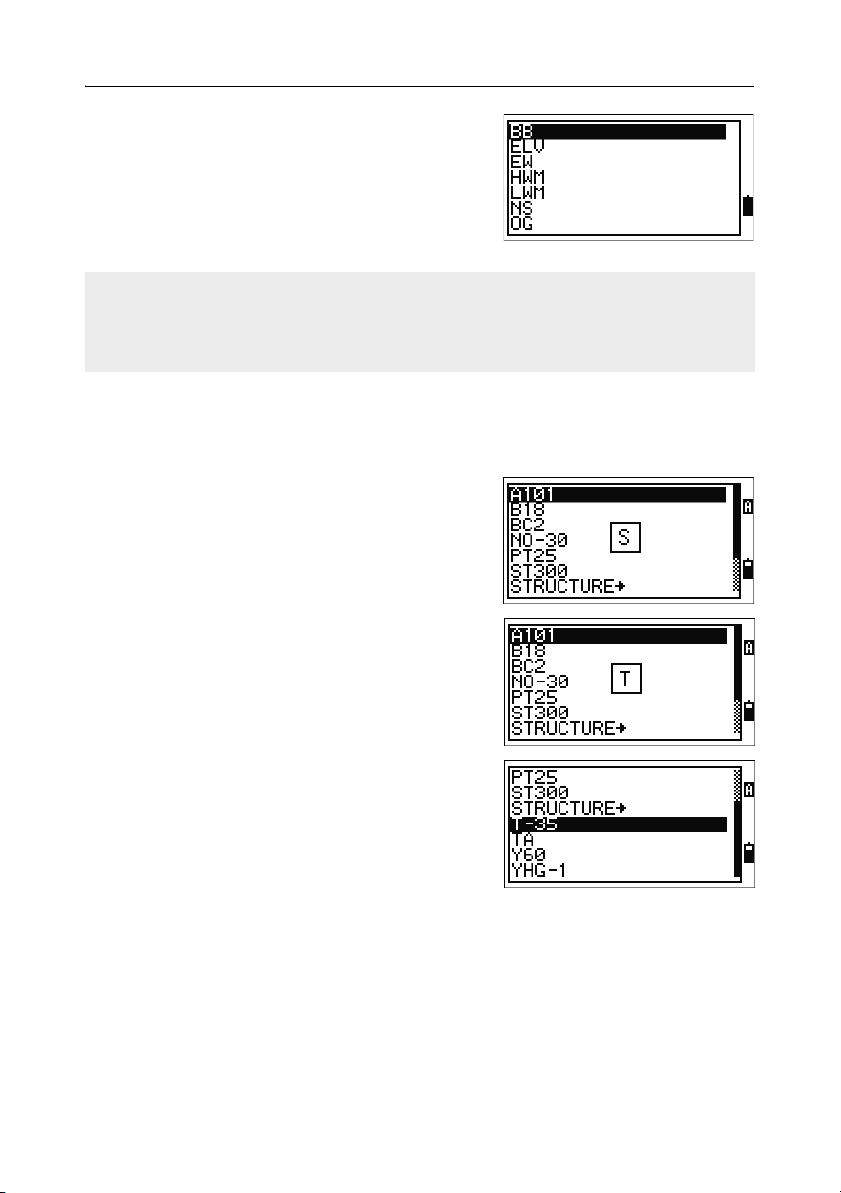
3 Getting Started
A layer has an arrow at the end of the code label.
If you highlight a layer in the list and then press
[ENT], the codes and layers in that layer are
displayed.
When you return to the input screen, the selected
code is entered in the CD field.
Items are shown in alphabetic order.
You can also use the first character search to quickly find a code. For more
information, see Advanced feature: Searching for a code by using the first
character, page 50.
Advanced feature: Searching for a code by using the first
character
To find a code quickly when the code list appears,
use the first-character search.
For example, to see feature codes that begin with
T, use the keypad to enter the letter T. To do this,
press
[1] twice.
After each press of the key, the input mode field
displays the selected letter. For example, if you
press
[1], S appears. If you quickly press [1] again,
T appears. If you do not press the [1] key again, the
letter T is selected.
Once you have selected a letter, the cursor moves
to the feature code beginning with that letter.
If there is no code beginning with that letter, the
cursor moves to the next available letter.
50 Total Station DTM-302 Series Instruction Manual
Page 71
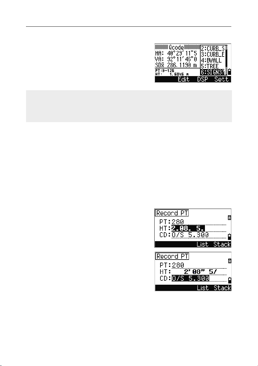
Getting Started 3
Qcodes
Quick codes (Qcodes) let you shoot and record
many points with feature codes in the field. You
can register up to ten Quick codes. To register
Qcodes, press the
Edit softkey. For more
information, see Quick code measurement mode,
page 37.
Press [MODE] to switch Qcodes on or off.
Press the Edit softkey to change the Qcode. You can edit the entire code, or just
the number at the end of the code.
You can still use [DSP] to change the background displays.
Entering values in feet and inches 32.3
When either US Survey Feet (US-Ft) or International Feet (I-Ft) is selected as the
distance unit, you can enter and display distances, HIs, HTs, and coordinate values
either in decimal feet, or in feet and inches For more information, see Unit,
page 135, and Others settings, page 136.
To enter values in feet and inches in an input screen, enter the elements, separated
by periods (.), in the following format:
<Feet> [.] <Inches> [.] <Numerator> [.] <Denominator> [ENT]
(0–11) (0–15) (0–99)
The default denominator is 16. If the denominator
is 16, you do not have to enter it, and it is not
displayed on the screen.
For example, if you enter
[2] [.] [0] [8] [.] [5] [.] [ENT], it appears as 2'08& 5/ (2
feet, 8 and 5/16ths inches).
Total Station DTM-302 Series Instruction Manual 51
Page 72

3 Getting Started
The following examples show how various values are entered:
To enter ... Type .. .
65' 5 3/8" [6] [5] [.] [5] [.] [3] [.] [8] [ENT]
65' [6] [5] [ENT]
65' 5" [6] [5] [.] [5] [ENT]
65' 5 3/8" [6] [5] [.] [5] [.] [6] [ENT]
5 3/8" [0] [.] [5] [.] [3] [.] [8] [ENT] or [0] [.] [5] [.] [6]
[ENT]
The numerator and denominator that you enter are automatically converted to the
closest value from the following list: 0, 1/8, 1/4, 3/8, 1/2, 5/8, 3/4, 7/8, 1/16, 3/16,
5/16, 7/16, 9/16, 11/16, 13/16, 15/16.
If the denominator is 16, it is not shown on the screen.
Jobs 3.3
To record data on the instrument, you must create or open a job.
Caution – Before you use the instrument for the first time, check the job
C
settings.
Creating a new job 33.1
1. Press [MENU] to open the MENU screen.
2. Press [1] to open the Job Manager.
3. Press the Creat softkey to open the Create
Job screen.
4. Enter the job name.
52 Total Station DTM-302 Series Instruction Manual
Page 73

Getting Started 3
5.
Press the Sett softkey to check the job
settings. You cannot change a job’s settings
once you have created the job.
6. Press [ENT] in the last field of the Job Sett
screen to create the new job.
If either of the messages MAX 32JOBs or Data Full appears, delete at least one
existing job to free space. You cannot free space by deleting records in an existing
job.
Creating a control job
A control job, or common file, stores coordinate data that is used by several field
jobs. You can create a control job in the office.
1. Press [MENU] to open the MENU screen.
2. Press [1] or select Job to open the Job
Manager.
3. Move the cursor to the job that you want to use
as the control job.
4. Press the Ctrl softkey.
5. Press the Yes softkey.
For more information, see Creating a control job,
page 53.
When you enter a point name or number, the system searches in the current job
first. If the point is not found in the current job, the search is automatically extended
to the control job. If the point is found in the control job, the selected point is copied
to the current job as a UP record.
Total Station DTM-302 Series Instruction Manual 53
Page 74

3 Getting Started
Jobs created before version 1.10
The current database version is 1.10. Jobs prefixed
with ? were created in earlier versions of the
database, and cannot be used in version 1.10.
If a job is from an earlier version, you cannot open
it, set it as the control job, or display its job
information. However, you can use the
softkey to delete it.
Jobs created in version 1.02 or earlier are not compatible with version 1.10 or later.
Download all jobs before you update the software that is running on the instrument.
DEL
Measuring Distances 3.1
Sighting a prism reflector 31.1
Warning – Never look at the sun through the telescope. If you do, you may
C
damage or lose your eyesight.
For information on how to assemble the prism reflector, see Setting Up the Prism
Reflector, page 18.
Sight the telescope to see crosshairs at the center of the
prism reflector.
Sighting a single prism
54 Total Station DTM-302 Series Instruction Manual
Page 75

When a reflected lightwave is detected, the signal level is
indicated.
Measuring distances 31.2
To take a distance measurement, press [MSR1] or
[MSR2] in the Basic Measurement Screen (BMS) or
in any observation screen.
While the instrument is taking a measurement, the
prism constant appears in a small font.
If the average count is set to 0, measurements are
taken continuously until you press
or
[ESC]. Each time a measurement is taken, the
distance is updated.
If the average count is set to a value from 1 to 99,
the averaged distance appears after the last shot.
The field name SD changes to SDx
averaged data.
[MSR1], [MSR2],
to indicate the
Getting Started 3
Sighting a tiltable single prism
Total Station DTM-302 Series Instruction Manual 55
Page 76

3 Getting Started
If the signal level is insufficient to take a measurement, the signal icon flashes on
and off. For more information, see Status bar, page 32.
To change the height of target (HT), temperature,
or pressure, press [HOT]. For more information,
see [HOT] key, page 39.
Settings that relate to corrections
(T-P corr, Sea Level, C&R corr., and Map
projection) are included in the job settings. These
settings are job-specific. If you need to change
any of these settings, you must create a new job.
For more information, see Job settings, page 113,
and Settings, page 131.
Measurement settings 31.3
To view the measurement settings,hold down
[MSR1] or [MSR2] for one second.
Use
[^] or [v] to move the cursor between the fields.
Use
[<] or [>] to change the value in the selected
field.
Field Values
Ta rg e t P r is m
Sheet
Const (prism constant) –999 mm through 999 mm
Mode Precise
Normal
AVE (Average count) 0 (Continuous) through 99
Rec mode One of the following:
MSR only
Confirm
ALL
56 Total Station DTM-302 Series Instruction Manual
Page 77

Getting Started 3
Targ e t f i el d
If the measurement is started with the Target field
set to Prism, there is a dash “–” in front of the
prism constant.
If the measurement is started with the Target field
set to Sheet, there is a right parenthesis “)” in
front of the prism constant.
The symbol then constantly runs from left to right over the prism constant in the
display.
The Target setting is used to apply better cyclic-error adjustment in distance
measurement. It efficiently eliminates multipath reflection.
Rec mode field
The Rec mode setting controls how the [MSR1] and [MSR2] keys operate in the BMS.
The MSR only setting is the default measurement mode. After a measurement, the
instrument stops in the BMS and waits for you to press [ENT] before recording the
point.
The Confirm setting displays the Record PT screen before data is recorded.
The ALL setting is a quick shooting and recording mode. The instrument
automatically records the point using the default PT/CD. The instrument then
returns to the BMS for the next measurement.
Total Station DTM-302 Series Instruction Manual 57
Page 78

3 Getting Started
58 Total Station DTM-302 Series Instruction Manual
Page 79

CHAPTER
4
Applications 4
In this chapter:
Q HA Reset and Angle Operations
Q Station Setup
Q Stakeout
Q Program Key
Q Recording Measurement Data
Q Measuring Offsets
Total Station DTM-302 Series Instruction Manual 59
Page 80

4 Applications
HA Reset and Angle Operations 4.1
To open the Angle menu, press [ANG] in the BMS.
To select a command from this menu, either press
the corresponding number key, or press
highlight the command and then press
F1/F2 is not supported by the DTM-332.
Setting the horizontal angle to 0 41.1
To reset the horizontal angle to 0, press [1] or select 0-Set in the Angle menu. The
display returns to the Basic Measurement Screen (BMS).
Entering the horizontal angle 41.2
To display the HA Input screen, press [2] or select
Input in the Angle menu. Use the numeric keys
to enter the horizontal angle. Then press
[<] or [>] to
[ENT].
[ENT].
To enter 123°45'50", type [1] [2] [3] [.] [4] [5] [5] [0].
The displayed value is rounded to the minimum angle increment.
Recording a foresight point after repeat angle measurement 41.3
1. To activate repeat angle measurement, press
[3] or select Rept. in the Angle menu.
HR=0 appears.
2. Sight the backsight and press [ENT].
3. Sight the foresight and press [ENT].
The horizontal angle is accumulated and the
value is held again.
4. To end repeat angle measurement, press [ESC].
60 Total Station DTM-302 Series Instruction Manual
Page 81

Applications 4
5.
When you have accumulated enough
horizontal angle between the backsight and the
foresight, press
[MSR1] or [MSR2] to take a
measurement to the foresight.
The averaged horizontal angle appears. This
value is fixed until the process is finished or
cancelled.
HRx = HR∑ ÷ N
HA = BSAz + HRx (normalized)
HRx is not updated even if the instrument is
moved.
6. Press [ENT] to store the foresight as a CP
record. Check the PT, HT, and CD values.
Then press
In repeat angle measurement, the HA is replaced by HR∑. The number of repeat
angles appears at the top of the screen (for example, N= 5).
Horizontal angles can be measured up to 1999°59'59".
This function stores both raw and XYZ data as CP records, regardless of the Store
DB setting.
[ENT] to record.
Face-1/Face-2 measurement 40.1
Use Face-1/Face-2 (F1/F2) measurements to obtain maximum accuracy for
measuring angles. Using F1/F2 measurements effectively cancels out mechanical
constant error, except for some special errors such as the vertical axis error. For
more information, see Face-1/Face-2 Measurements, page 20.
F1/F2 measurements are not available with the DTM-332.
To take F1/F2 data without taking a distance
measurement, press
Angle menu.
[4] or select F1/F2 in the
Total Station DTM-302 Series Instruction Manual 61
Page 82

4 Applications
If you have already taken a distance measurement
to the target, you can initiate F1/F2 averaging by
flipping the telescope to the other face.
For the HA to be adjusted from a F1/F2
measurement, the Backsight must also have
been measured in F1/F2 during the station setup.
Horizontal angle hold 40.2
To hold the horizontal angle to the current value,
press
[5] or select Hold in the Angle menu.
To set the horizontal angle to the displayed value,
press
[ENT] or the Set softkey.
To cancel the process and return to the Basic
Measurement Screen (BMS), press
Abrt softkey.
[ESC] or the
Station Setup 4.1
To open the Stn Setup menu, press [STN] in the
BMS.
To select a command from this menu, press the
corresponding number key. Alternatively, press
or
[>] to highlight the command and then press
[ENT]. Press [^] or [v] to move up or down one page.
The last function used is highlighted.
62 Total Station DTM-302 Series Instruction Manual
[<]
Page 83

Applications 4
Setting up a station with known coordinates or azimuth 41.1
1. Press [1] or select Known in the Stn Setup
menu.
2. Enter a point name or number in the ST field.
– If the input point number or name is an
existing point, its coordinates are displayed
and the cursor moves to the HI (Height of
instrument) field.
– If the point is new, a coordinate input
screen appears. Enter the coordinates for
the point. Press
you press
point is stored.
– If the specified point has a code, the code
appears in the CD field.
3. Enter the instrument height in the HI field and
then press
[ENT].
[ENT] after each field. When
[ENT] in the CD field, the new
The Backsight screen appears.
4. Select an input method for defining the
backsight point.
– To sight the backsight by entering
coordinates, see below.
– To sight the backsight by entering the
azimuth and angle, see page 66.
Total Station DTM-302 Series Instruction Manual 63
Page 84

4 Applications
Sighting the backsight by entering coordinates
Z
X0
1.
To enter coordinates for the backsight point
(BS), press
[1] or select Coord in the
X
Xb
Instrument height
Y0 Yb
Station point
(Xi, Yi, Zi)
Backsight screen.
2. Enter the point name. If the point exists in the
job, its coordinates are shown.
3. If you intend to take a distance measurement
to the BS, enter the height of target in the HT
field.
4. Sight the BS on Face-1 (F1). Press [ENT] to
complete the setup.
– To record a full shot (with HA, VA, and SD
values) to the BS, press
AZ Azimuth calculated by coordinates
[MSR1] or [MSR2].
Backsight point
(Xb, Yb, Zb)
Y
– If you are measuring to a known
coordinate BS, press
[DSP] to display a QA
screen. The QA screen shows the dHD and
dVD values, which indicate the difference
between the measured distance and the
distance calculated from the known
coordinates.
64 Total Station DTM-302 Series Instruction Manual
Page 85

5.
To record the station, press [ENT].
6. To finish the station setup after taking a
distance measurement, press
[ENT]. ST and F1
records are stored to the current job.
Advanced feature: Measuring F1 and F2
F1/F2 measurements are not available with the DTM-332.
To take an angle shot and proceed to the next
measurement on Face-2, press the
To go directly to the Face-2 measurement after
taking a distance measurement to the BS on
Face-1, flip the telescope. The instrument
automatically detects F1/F2.
F2 softkey.
Applications 4
Press
[ENT] on Face-2. The delta screen appears.
To record a CP record which stores the averaged
HA, VA, and SD from the F1/F2 data, press the
CP softkey. To record only the ST and F1/F2
records, without a CP record, press the
OK
softkey.
Total Station DTM-302 Series Instruction Manual 65
Page 86

4 Applications
Sighting the backsight by entering the azimuth angle
Z
X0
To enter the azimuth angle to the backsight
1.
point, press
X
Azimuth
Station point
(Xi, Yi, Zi)
Instrument height
Y0
[2] or select Angle in the
Backsight point
Backsight screen.
2. If there is no point name for the BS, press [ENT]
on the BS field.
3. In the AZ field, enter the azimuth angle to the
BS point.
Y
If you press
[ENT] without entering a value in
the AZ field, the azimuth is automatically set
to 0°00'00".
4. Sight the BS point and press [ENT]. ST and F1
records are stored in the job.
You can also use the
F2 softkey for F1/F2
measurements. See Advanced feature:
Measuring F1 and F2, page 65.
66 Total Station DTM-302 Series Instruction Manual
Page 87

Applications 4
The F2 softkey is not available on the DTM-332.
Setting up a station using multiple point resection 40.1
A resection sets up the station using angle/distance measurements to known points.
X
Z
X1
X2
X0
Y1 Y0 Y2
Height 1
Known point 1
(X1, Y1, Z1)
Station point (Xi, Yi, Zi)
Instrument height
Height 2
Known point 2
(X2, Y2, Z2)
Y
You can use a maximum of 10 points in a resection. Measurements can be distance
and angle, or angle only. Calculation starts automatically when enough
measurements are taken.
You can delete poor observations and recalculate if necessary. You can also select
the BS point.
If the angle between known point 1 and known point 2 (measured from the station
point) is extremely acute or extremely oblique, the resulting solution will be less
reliable geometrically. For geometric reliability, select known point locations (or
station point locations) that are widely spaced.
Total Station DTM-302 Series Instruction Manual 67
Page 88

4 Applications
1.
To start the resection, press [2] or select
Resection in the Stn Setup menu.
2. Enter the point name for the first observation
point (PT1).
3. Enter the target height and press [ENT].
4. Sight PT1 and press [MSR1] or [MSR2].
To use the
F2 softkey for F1/F2
measurements, see Advanced feature:
Measuring F1 and F2, page 65.
The F2 softkey is not available on the DTM-332.
5. To proceed to the next point, press [ENT].
6. Enter the second point (PT2) and its height of
target.
68 Total Station DTM-302 Series Instruction Manual
Page 89

7.
Measure to PT2 and press [ENT].
When the instrument has enough data, it
calculates the station (STN) coordinates.
– If more than the minimum required data is
available, a standard deviation screen
appears.
– To take measurements to strengthen
geometry of the resection, press the
softkey. For information about the
Add
View
softkey, see Advanced feature: Viewing
and deleting a measurement in resection, page 70.
8. When the results are satisfactory, record the
station. To do this, press
[ENT] or the REC
softkey.
9. Enter the height of instrument, if required.
Press
[ENT]. The ST field defaults to the last
recorded PT + 1.
10. To change the station name, move to the ST
field and edit or replace the text.
Applications 4
If you have set Split ST to Yes, the ST field defaults to the last recorded ST
value + 1. For more information, see Others settings, page 136.
BS defaults to the first observed point.
11. To change the BS, press the Change softkey.
Total Station DTM-302 Series Instruction Manual 69
Page 90

4 Applications
12.
Select the BS point that you want to use and
press
[ENT].
13. To finish the resection setup, move the cursor
to the BS field and press
The minimum data required for a resection is either three angle shots, or one angle
shot and one distance shot. If you use a distance shot, the distance between the
target points must be greater than the measured distance.
Stn-Z is calculated from distance-measured data. If no distances are measured,
then Stn-Z is calculated using angle-only measurements to points with 3D
coordinates.
[ENT].
Advanced feature: Viewing and deleting a measurement in
resection
To check the measurements to each known point,
press the
View softkey on the calculated STN
(sigma or coordinate) screen.
dHA Distributed HA errors in each direction
dVD VD errors between measured distance
and calculated distance
dHD HD errors between measured distance
and calculated distance
To delete a measurement (because of large sigma
values, for example), highlight the measurement
data or display the detail screen for the measurement. Then press the
The STN coordinates are automatically recalculated.
70 Total Station DTM-302 Series Instruction Manual
DEL softkey.
Page 91

Applications 4
To continue resection observations, press the Add
softkey. The input screen for the next PT appears.
Setting up the station quickly without coordinates 40.1
The station point (ST) in this function defaults to a new point number. For the new
point, MP (0, 0, 0) is stored as the coordinates. When the ST is manually changed to
a known point name, the station is set up on the coordinates of the known point.
1. To enter Quick Station setup, press [3] or select
Quick in the Stn Setup menu.
ST Station point (defaults to the last
recorded PT + 1, or ST + 1, depending
on the Split ST setting)
HI Height of instrument
BS Backsight point (blank)
AZ Backsight azimuth (defaults to zero)
2. No default PT is assigned to the BS. Leave this
field blank, or enter a BS point name.
3. The backsight azimuth (AZ) defaults to zero,
but you can change this.
4. To complete the station setup, sight the BS and
press
[ENT].
When you press
have entered.
[ENT] in the AZ field, both HA and AZ are reset to the value you
Even if both ST and BS are known points, this function does not calculate the
backsight angle (AZ) automatically. To calculate the AZ between two known points
(ST and BS), use Station Setup > Known. For more information, see
Setting up a station with known coordinates or azimuth, page 63.
Total Station DTM-302 Series Instruction Manual 71
Page 92

4 Applications
Determining station elevation 40.1
1. Press [4] or select Remote BM in the Stn
Setup menu.
2. Enter the BM point and press [ENT]. When the
point is found, it appears briefly. The cursor
then moves to the HT field.
3. Enter the HT and press [ENT].
4. Sight the BM point and press [MSR1] or [MSR2].
5. To take an F1/F2 measurement, press the F2
softkey or flip the telescope to Face-2 after a
distance measurement.
The F2 softkey is not available on the DTM-332.
The updated station coordinates are displayed.
You can change the HI in this screen.
6. To record the updated STN, press [ENT].
When the HI is changed, the Z coordinate is updated before the station is recorded.
You must complete a station setup before you use the Remote Benchmark function.
72 Total Station DTM-302 Series Instruction Manual
Page 93

Applications 4
Checking and resetting the backsight direction 40.1
You must complete a station setup before you use the BS check function.
This function always refers to the backsight point from the last ST record stored in
the current open job.
1. To enter the backsight (BS) check function,
press
[5] or select BS Check in the Stn Setup
menu.
HA Current HA reading
BS The HA to the BS in the last station
setup. Enter station coordinates for
observations without recording data
Do one of the following:
2.
– To reset the horizontal angle to the HA set
in the last station setup sight the BS and press the
[ENT].
– To cancel the process and return to the BMS, press the
press
[ESC].
Reset softkey or press
Abrt softkey or
Total Station DTM-302 Series Instruction Manual 73
Page 94

4 Applications
Base XYZ function:
Base XYZ does not store a ST record, so the BS Check cannot check the backsight
when you enter a station using Base XYZ.
To store raw data, use one of the other functions in the Stn Setup menu. This
function does not store an ST record in the job.
You can use this function without an open job. If there is an open job when you use
this function, a CO record is stored to indicate that the instrument’s base
coordinates have changed.
To enter the Base XYZ function, press [6] or
1.
select
Base XYZ in the Stn Setup menu.
The current instrument XYZ values are shown
as the default.
2. Enter the new instrument XYZ values and
press
[ENT].
3. Do one of the following:
– To reset the horizontal angle, enter a value in the HA field and press
[ENT].
– If you do not need to reset the HA, leave
the HA field blank and press
[ENT].
The display returns to the BMS.
74 Total Station DTM-302 Series Instruction Manual
Page 95

Applications 4
Two-point resection along a known line 40.1
1. To enter the Known Line function, press [7] or
select
Known Line in the Stn Setup menu.
2. Enter a known point as P1.
If you enter a new point name, a coordinate
input screen appears.
Sight P1 and press
measurement. Press
3. Choose how you want to define a known line:
[MSR1] or [MSR2] to take a
[ENT].
– To define the line by entering P2
coordinates, press
[1] or select By Coord.
– To define the line by entering the azimuth,
press
[2] or select By Angle.
4. If you select By Angle, the azimuth input
screen appears. Enter the angle value and press
[ENT].
A measurement screen appears.
5. Sight P2 and press [MSR1] or [MSR2] to take a
measurement. Press
[ENT].
Total Station DTM-302 Series Instruction Manual 75
Page 96
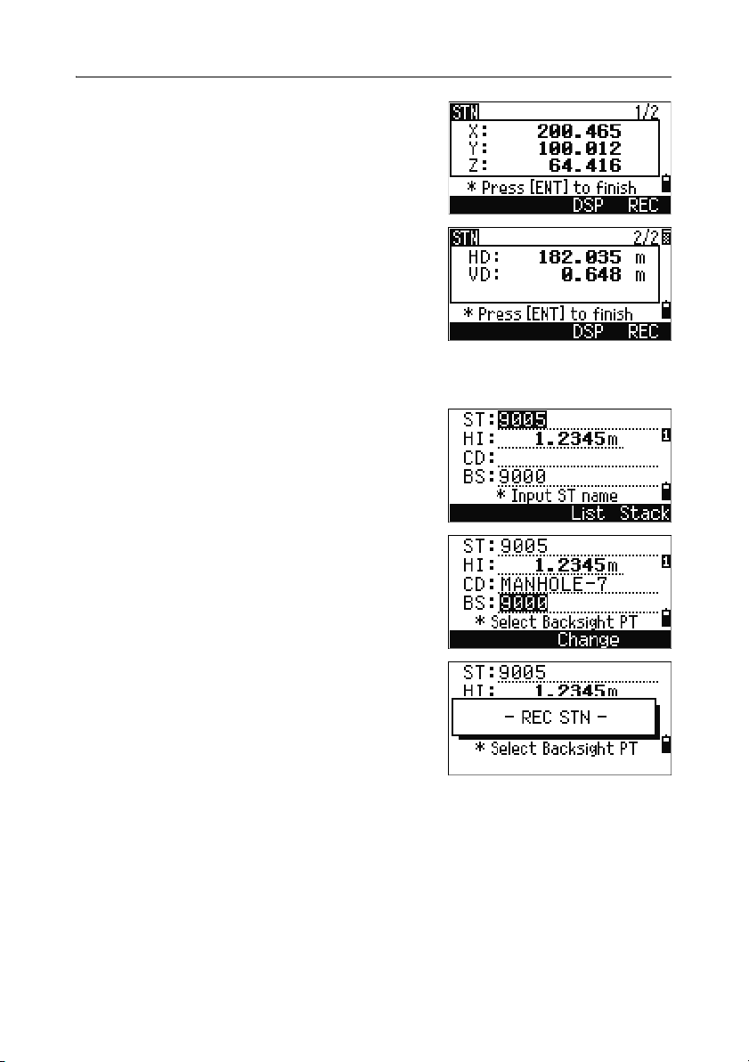
4 Applications
After the measurement to P2 is completed, the
coordinates of the station are calculated.
6. To record the station, press [ENT] or the REC
softkey.
7. To check your measurement, press the DSP
softkey. If you defined the line by entering its
azimuth, HD and VD between P1 and P2 are
displayed.
If you defined the line by entering the P2
coordinates, the difference of HD (dHD) and
VD (dZ) between your measurement data and
input coordinate data are displayed.
8. Enter the station name, the height of
instrument (HI), and a feature code (CD) if
required. The station name defaults to the last
recorded PT + 1, or last recorded ST + 1,
depending on the Split ST setting.
9. Backsight (BS) defaults to the first point (P1).
To change it, highlight the BS field and then
press the
Change softkey.
10. To finish the setup and record the station, press
[ENT] in the BS field.
Sample records
CO, Temperature:20C Pressure:1013hPa Prism:0 …
ST,9005, ,265, ,1.2350,150.40300,150.40300
F1,265,1.6040,79.0010,90.30150,89.35260,
F1,200,1.4590,50.2300,269.4035,93.50110,
CO, P1-P2 HD=122.0350 VD=0.5600
76 Total Station DTM-302 Series Instruction Manual
Page 97

Applications 4
Stakeout 4.1
FiLL
R
IN
OUT
CUT
L
To display the Stakeout menu, press [S-O].
IN OUT
Height
of target
R
L
FILL
CUT
Specifying the stakeout point by angle and distance 41.1
1. To display the input screen for the distance and angle to the target, press [1] or
select
HA-HD in the Stakeout menu.
2. Enter the values and press [ENT].
HD Horizontal distance from station point to
stakeout point
dVD Vertical distance from station point to
stakeout point
HA Horizontal angle to stakeout point
Total Station DTM-302 Series Instruction Manual 77
Page 98

4 Applications
If you press [ENT] without entering HA, the current HA is used.
3.
Rotate the instrument until the dHA is close to
0°00'00".
4. Sight the target and press [MSR1] or [MSR2].
When the measurement is completed, the
differences between the target position and the
stakeout point are displayed.
dHA Difference in horizontal angle to the
target point
R/L Right/Left (Lateral error)
IN/OUT In/Out (Longitudinal error)
CUT/FIL Cut/Fill
Once a measurement is taken, the Cut/Fill value and Z coordinate are updated as
the VA is changed.
If you press [HOT] in any observation screen, the
HOT key menu appears. You can use this menu at
any time to change HT and T-P.
78 Total Station DTM-302 Series Instruction Manual
Page 99

Applications 4
Using [DSP] to switch between display screens
Press [DSP] to switch between the Stakeout display screens. The following screens
are available:
S-O1 S-O2 S-O3 S-O4
dHA←
R←
OUT↑
CUT↑
S-O5 S-O6 S-O7 S-O8
X
Y
Z
HA
VA
SD
dX
dY
dZ
HA
VD
HD
rSD
rVD
rHD
HL
V%
HD
HD
VD
SD
The S-O8 screen is only available if the secondary distance unit is set. For more
information, see Others settings, page 136.
Every time you press
[DSP], the next screen appears. If you press [DSP] in the last
screen (S-O7, or S-O8 if the secondary distance unit is set), the S-O1 screen
appears.
To customize the S-O2, S-O3, and S-O4 screens, hold down
[DSP] for one second.
For more information, see Customizing items in the Basic Measurement Screen
(BMS), page 36.
To record the stakeout point, press
[ENT]. PT
defaults to the last recorded PT+1.
Press
[ENT] to record the point.
After recording the point, it returns to the
observation screen. You can continue observation,
or press
[ESC] to input another angle and distance
for stakeout.
Total Station DTM-302 Series Instruction Manual 79
Page 100

4 Applications
Specifying the stakeout point by coordinates 40.1
1. To start a stakeout by coordinates, press [2] or
select
XYZ in the Stakeout menu.
2. Enter the point name that you want to stake
and press
You can also specify the point by code or
radius from the instrument.
If several points are found, they are displayed
in a list. Use
list. Use
3. Highlight a point in the list and press [ENT].
The delta angle and the distance to the target
are shown.
4. Rotate the instrument until the dHA is close to
0°00'00". Press
dHA Difference in horizontal angle to the
HD Distance to the target point
Ask the rodman to adjust the target position.
5.
When the target is on the intended position,
the displayed errors become 0.000 m (or
0.000 ft).
dHA Difference in horizontal angle to the
R/L Right/Left (Lateral error)
IN/OUT In/Out (Longitudinal error)
CUT/FIL Cut/Fill
[ENT].
[^] or [v] to move up and down the
[<] or [>] to move up or down one page.
[MSR1] or [MSR2].
target point
target point
80 Total Station DTM-302 Series Instruction Manual
 Loading...