

Nikon D70 Repair manual
作成承認印 配布許可印
Copyrighc2004 by Nikon Corporation.
All Rights Reserved.
無断転載を禁ず
!!
Printed in Japan February 2004
VBA10401-R.3623.A
社 外 秘
TEMPORARY
VBA10401
REPAIR MANUAL
修 理 指 針
- M1・ -
VBA10401-R.3623.A
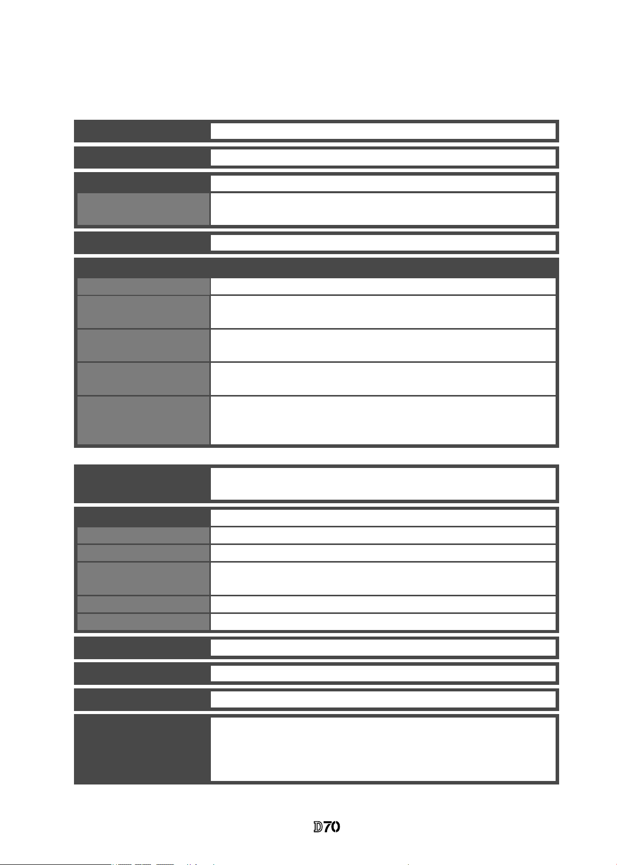
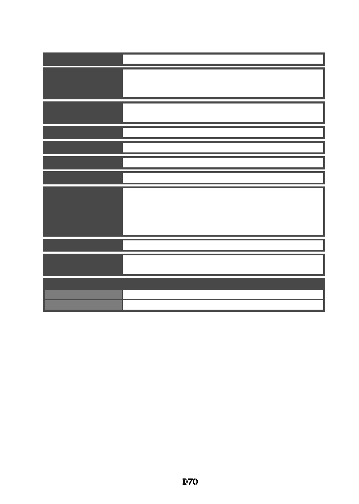
Type
Single-lens reex digital camera with interchangeable lenses
CCD
23.7 × 15.6 mm; total pixels: 6.31 million
Image size (pixels)
• 3008 × 2000 (Large)
Effective pixels
6.1 million
Lens mount
Nikon F mount (with AF coupling and AF contacts)
Compatible lenses
*
Type G or D AF Nikkor
All functions supported
Other AF Nikkor
†
All functions supported except 3D color matrix metering
and i-TTL Balanced Fill-Flash for Digital SLR
Micro Nikkor 85 mm
f/2.8D
All functions supported except autofocus and some
exposure modes
AI-P Nikkor
All functions supported except 3D color matrix metering,
i-TTL Balanced Fill-Flash for Digital SLR,
and autofocus
Non-CPU
Can be used in mode M, but exposure meter does not
function; electronic range nder can be used if maximum
aperture is f/5.6 or faster
Picture angle
Equivalent in 35-mm format is approximately 1.5 times
lens focal length
Viewnder
Diopter adjustment
– 1.6 – +0.5 m
– 1
Focusing screen
Type B BriteView clear matte screen Mark V with
superimposed focus brackets and On-Demand grid lines
Eyepoint
18 mm ( – 1.0 m
– 1
)
Frame coverage
Approximately 95% of lens (vertical and horizontal)
Magnication
Approximately 0.75 × (50-mm lens at innity; –1.0 m
– 1
)
Optical xed pentaprism
* IX Nikkor lenses can not be used † Excluding lenses for F3AF
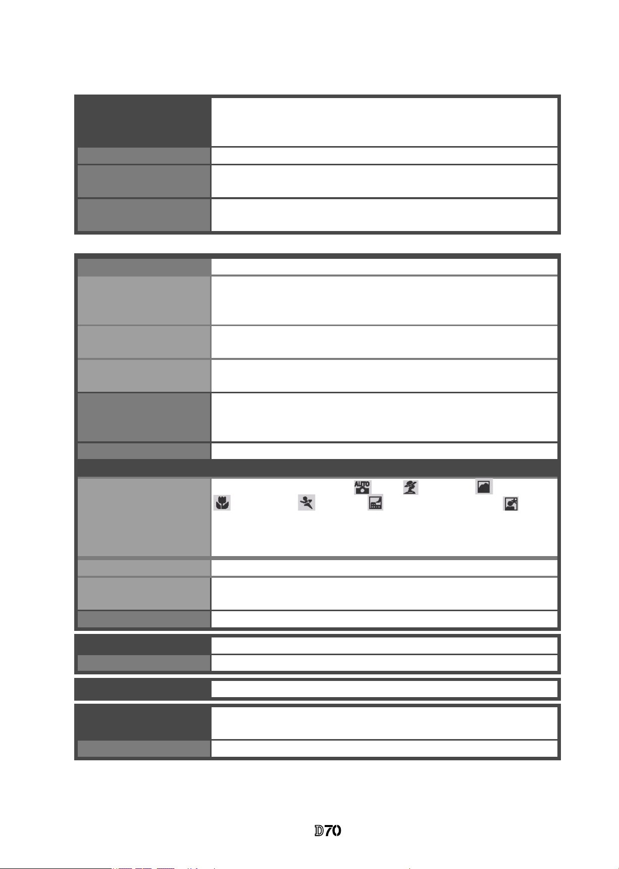
Reex mirror
Quick return
Lens aperture
Instant return with depth-of-eld preview
Focus-area selection
Can be selected from 5 focus areas
Lens servo
• Autofocus (AF): Instant single-servo AF (AF-S);
continuous-servo AF (AF-C); predictive focus tracking
automatically activated according to subject status
• Manual focus (M)
• 2240 × 1448 (Medium)
• 1504 × 1000 (Small)
Specications
- M2・ -
VBA10401-R.3623.A
Autofocus
Detection range
– 1 – +19 EV (ISO 100 at 20 ° C/68 ° F)
AF-area mode
Single-area AF, dynamic-area AF, dynamic-area AF with
closest subject priority
Focus lock
Focus can be locked by pressing shutter-release button
halfway (single-servo AF) or by pressing AE-L/AF-L
button
TTL phase detection by Nikon Multi-CAM900 autofocus
module with AF-assist illuminator (range approximately
0.5 –3.0 m / 1 ´ 8˝–9´ 10˝)
Exposure
Metering
Three-mode through-the-lens (TTL) exposure metering
Matrix
3D color matrix metering (type G and D lenses); color
matrix metering (other CPU lenses); metering performed
by 1,005-pixel RGB sensor
Center-weighted
Weight of 75% given to 6, 8, 10, or 12-mm circle in
center of frame
Spot
Meters 2.3-mm circle (about 1% of frame) centered on
active focus area
Range
(ISO 100 equivalent, f/1.4
lens, 20 °
C/68 ° F)
0 – 20 EV (3D color matrix or center-weighted metering)
3 – 20 EV (spot metering)
Exposure meter coupling
CPU coupling
Exposure control
Operating mode
Digital Vari-Program ( auto, portrait, landscape,
c l o se u p , s p o rts, ni g h t l a n d s c a p e , ni g h t
portrait), programmed auto (P) with exible program;
shutter-priority auto (S); aperture priority
auto (A);
manual (M)
Exposure compensation
– 5 – +5 EV in increments of
1
/
3
or EV
Bracketing
Exposure and / or ash bracketing (2 – 3 exposures in
increments of
1
/
3
or EV)
Exposure lock
Luminosity locked at detected value with AE-L/AF-L
button
Shutter
Speed
30 –
1
/
8000
s in steps of
1
/
3
or EV, bulb, remote
Combined mechanical and CCD electronic shutter
Sensitivity
200 – 1600 (ISO equivalent) in steps of
1
/
3
EV
White balance
Bracketing
2 –3 exposures in increments of 1
Auto (TTL white-balance with 1,005 pixels RGB sensor),
six manual modes with ne-tuning, preset white balance
- M3・ -
VBA10401-R.3623.A
Storage
Media
Type I and II CompactFlash memory cards; Microdrives
File system
Compliant with Design Rule for Camera File System (DCF)
2.0 and Digital Print Order Format (DPOF)
Compression
• NEF (RAW): compressed 12-bit
• JPEG: JPEG baseline-compliant
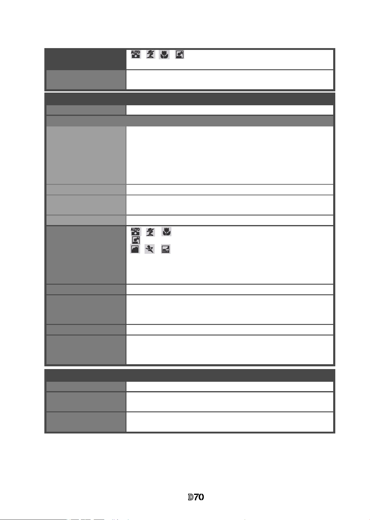
Built-in Speedlight
Guide number
(m / ft at 20 °
C/68 °F)
• ISO 200: approximately 15/49 (manual 17/56)
• ISO 100: approximately 11/36 (manual 12/39)
• , , , : auto ash with auto pop-up
• P, S, A, M: manual pop-up with button release
Flash
Sync contact
X-contact only; ash synchronization at up to
1
/
500
s
Sync modes
•
, , : front curtain sync, red-eye reduction
• : slow sync, slow sync with red-eye reduction
• , , : front curtain sync and red-eye reduction
available with optional Speedlights
• P, S, A, M: front curtain sync, slow sync, rear-curtain
sync, red-eye reduction, slow sync with red-
eye reduction
Flash-ready
indicator
Lights when SB-series Speedlight such as 800, 600,
80DX, 28DX, 50DX, 28, 27, or 22s is fully charged;
blinks for 3 s after ash is red at full output
Flash control
TTL
TTL ash control by 1,005-pixel RGB sensor (CPU lenses only)
• Built-in Speedlight: i-TTL balanced ll-ash for digital
SLR, or standard i-TTL ash for digital SLR (spot metering
or mode dial set to M)
• SB-800 or 600: i-TTL balanced ll-ash for digital
SLR, or
standard i-TTL ash for digital SLR (spot metering)
Auto aperture
Available with SB-800 with CPU lens
Non-TTL auto
Available with such Speedlights as SB-800, 80DX, 28DX,
28, 27, and 22s
Range-priority
manual
Available with SB-800
Flash compensation
– 3 – +1 EV in increments of
1
/
3
or EV
Creative Lighting
System
Supports Flash Color Information Communication and
FV lock with built-in Speedlight, SB-800, and SB-600.
SB-800 and 600 also support Advanced Wireless Lighting.
Accessory shoe
Standard ISO hot-shoe contact with safety lock
- M4・ -
VBA10401-R.3623.A
Video output
Can be selected from NTSC and PAL
External interface
USB
Tripod socket
˝ (ISO)
Power source
• One rechargeable Nikon EN-EL3 Li-ion battery; charging
voltage (MH-18 quick charger or optional MH-19 multi
charger): 7.4 V DC
• Three CR2 lithium batteries (with MS-D70 battery holder)
• EH-5 AC adapter (available separately)
Dimensions
(W × H × D)
Approximately 140 × 111 × 78 mm (5.5˝ × 4.4˝ × 3.1˝)
Weight
Approximately 595 g (1 lb 5 oz) without battery, memory
card, body cap, or monitor cover
Operating environment
Temperature
0 – 40 ° C (32 – 104 ° F)
Humidity
Less than 85% (no condensation)
• Unless otherwise stated, all gures are for a camera with a fullycharged battery operating at an ambient temperature of 20 °C (68 °F).
Self-timer
Electronically controlled timer with 2 – 20 s duration
Depth-of-eld
preview
When CPU lens is attached, lens aperture can be stopped
down to value selected by user (A and M modes) or value
selected by camera (Digital Vari-Program, P, and
S modes)
Monitor
1.8˝, 130,000-dot, low-temperature polysilicon TFT LCD
with brightness adjustment
Firmware upgrades
Firmware can be upgraded by user
VBA10401-R.3623.A
- D1 ・ -
Disassembly
�
内部に高電圧部あり。カバーを外す 時は感電に注意すること。
カバーを外した後は、修理指針の指 示に従ってメインコンデン
サーの放電を必ず行うこと。
警告
Note
: ①
When disassembling/(re)assembling, be sure to use the conductive mat (J5033) and wrist strap
(J5033-5) for static protection of electrical parts.
②
Before disassembling, be sure to remove batteries or AC power wires.
③
When disassembling, make sure to memorize the processing state of wires and FPC, screws to be
xed and their types, etc.
④
Because the low pass lter of the imaging CCD PCB is easily damaged, handle it with enough
care.
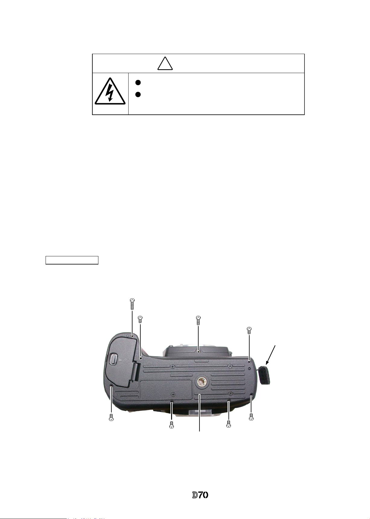
1. Separate Front and Rear bodies
#692
#697
#677×6
Bottom cover
Open I/F cover
WARNING
Due to an internal high voltage area, take extra care not to get an
electric shock when detaching covers.
After removing covers, be sure to discharge the main condenser
according to the instructions of the repair manuals.
Bottom Cover
VBA10401-R.3623.A
- D2 ・ -
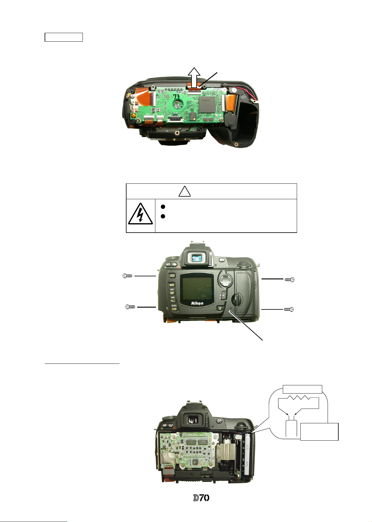
Rear cover
・
Remove the TFT-PCB connection FPC from the connector.
・
Take out 4 screws (#612).
・
Remove the rear cover.
#612×4
Rear cover
�
内部に高電 圧部 あり 。カ バーを外す時は感電に注意す るこ と。
カバーを外 した 後は 、修 理指針の指示に従ってメイン コン デン
サーの放電 を必 ず行 うこ と。
警告
TFT-PCB connection FPC
Discharge Main condenser
・
Discharge the main condenser from its both ends.
2KΩ/5W
Main
condenser
WARNING
Due to an internal high voltage area, take extra care not to get an
electric shock when detaching the covers.
After removing the covers, be sure to d is ch arge t he main
condenser according to the instructions of the repar manuals.
VBA10401-R.3623.A
- D3 ・ -
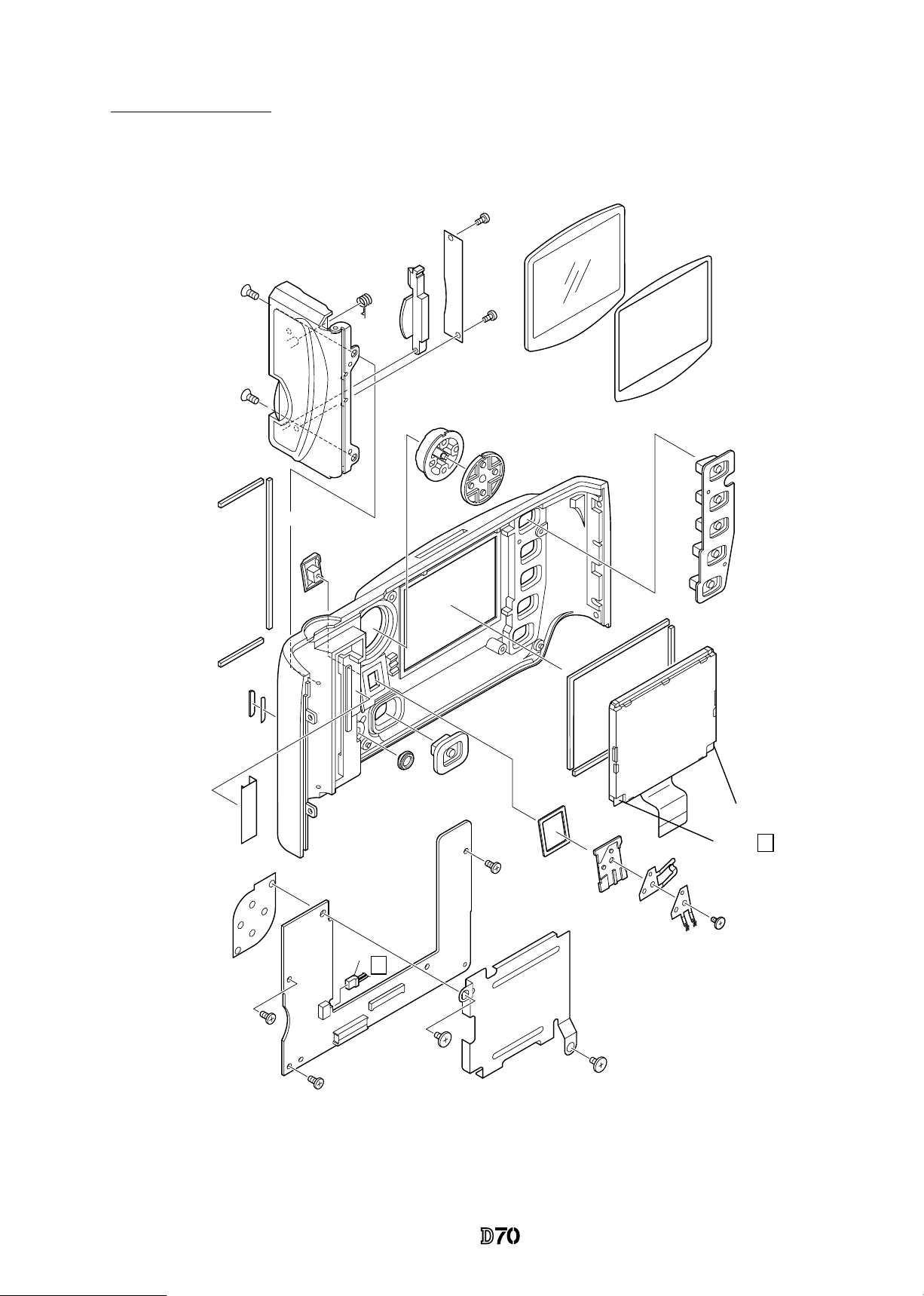
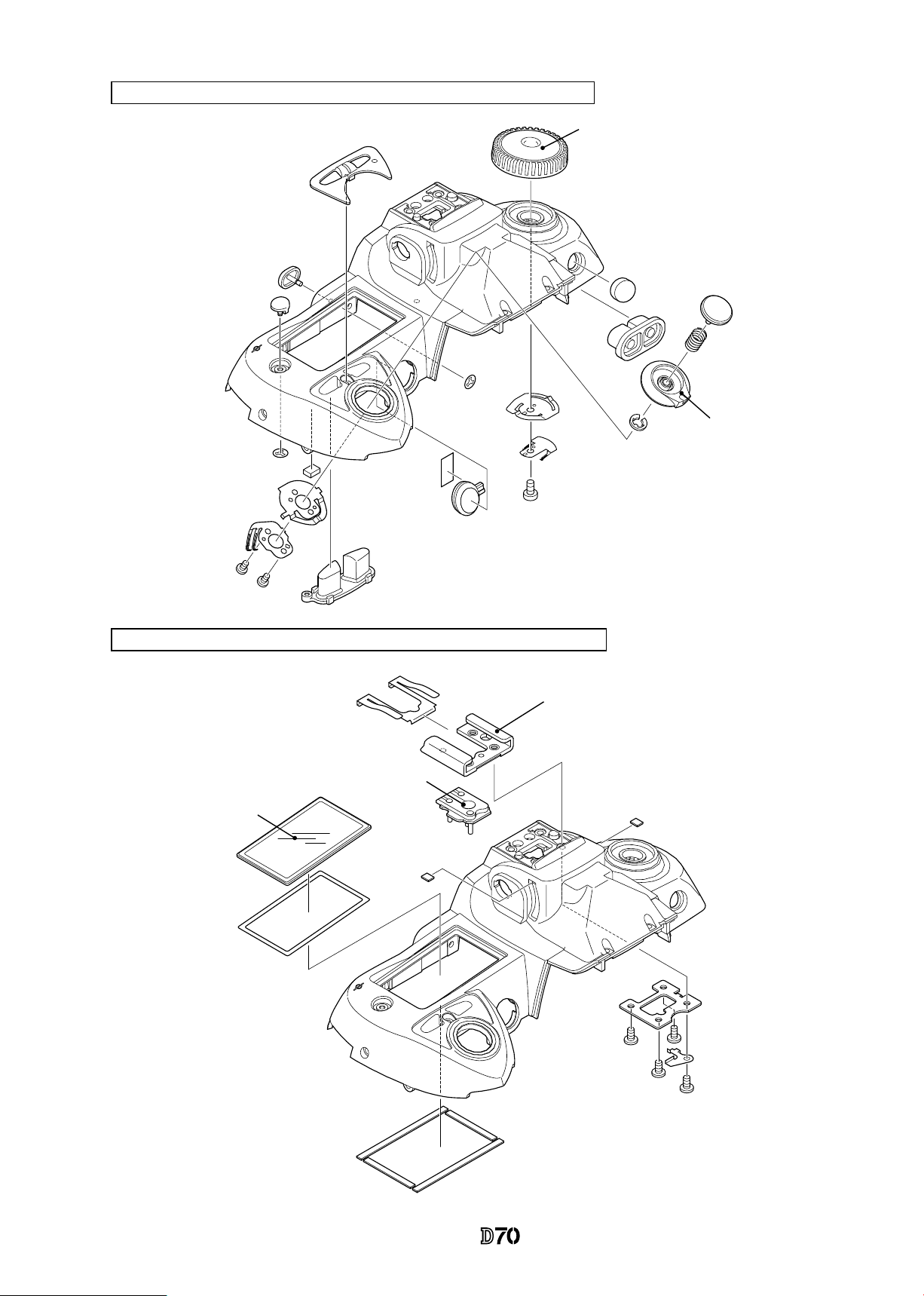
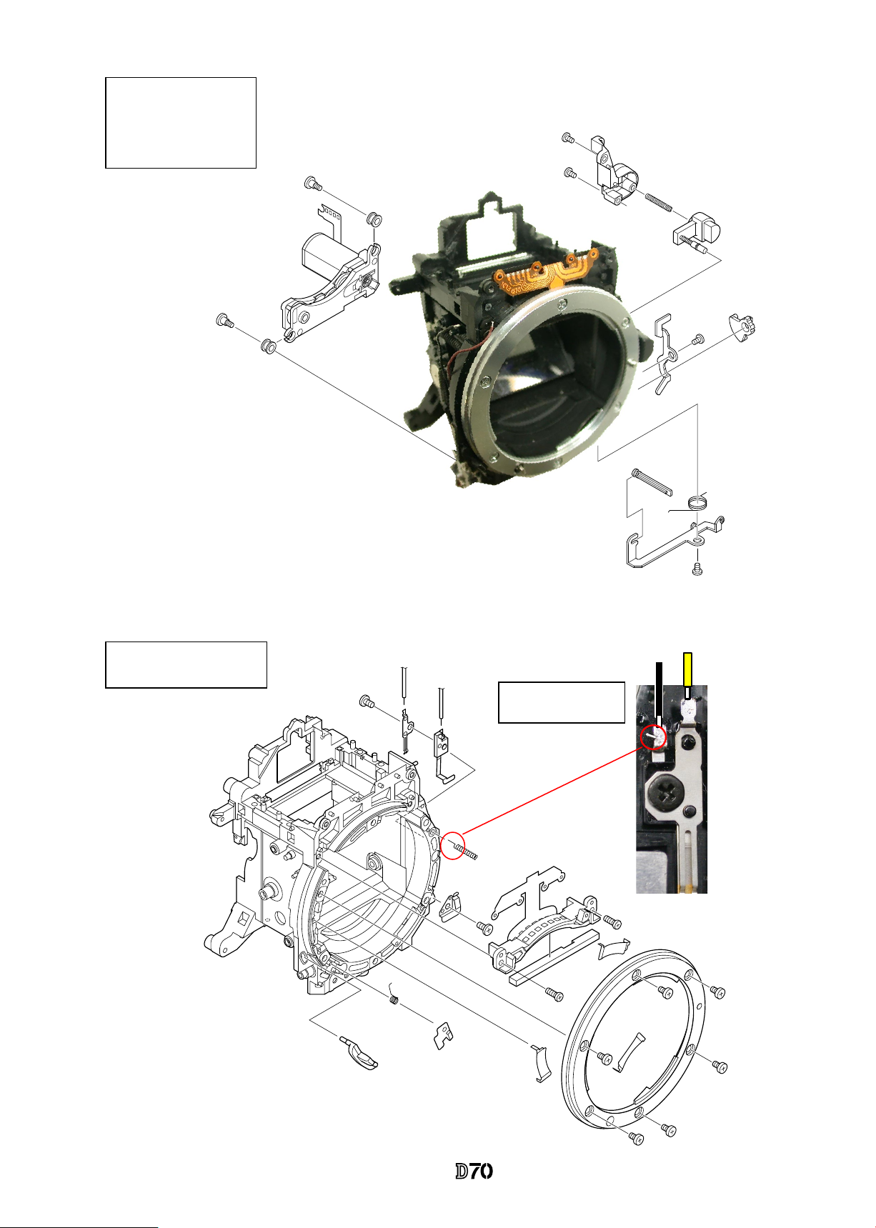
Disassemble Rear cover
Black
Gray
A
A
#402
#403
#421
#B431
#413
#412
#423
#408
#416
#443
#444
#409
#414
#B2036
#665×3
#406
#666×2
#668
#419
#418
#417
#420
#404×2
#1031
#1071
#435
#432
#605×2
#437
#426×2
#425
#678×2
VBA10401-R.3623.A
- D4 ・ -
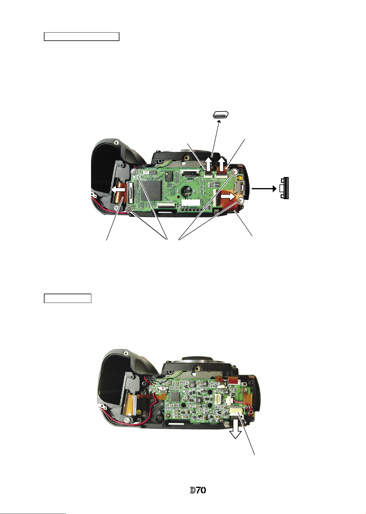
Memory compression PCB
・
Remove the USB gasket (#B481) from the memory compression PCB (#B2033).
・
Remove the connection FPCs from each connector which are connected from the CF PCB, I/F PCB, main
PCB, and CCD PCB.
・
Remove the ferrite core (#1133) from I/F PCB connection FPC.
・
Take out 4 screws (#679) to detach the memory compression PCB (#B2033).
CCD-PCB unit
・Remove the CCD-PCB connection harness.
CCD-PCB connection harness
Main PCB connection FPC
I/F PCB connection FPC
CF PCB connection FPC
CCD PCB connection FPC
#B481
#1133
#679×4
#B2033
VBA10401-R.3623.A
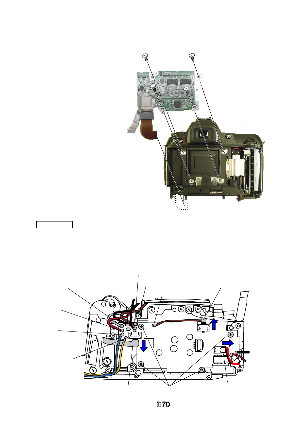
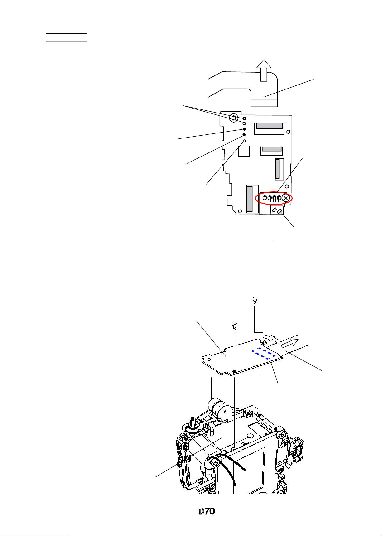
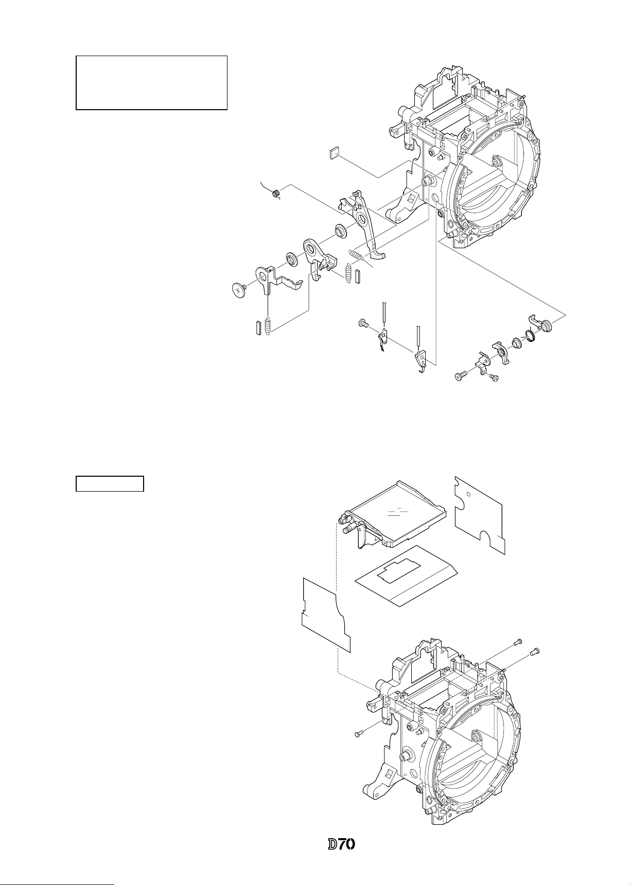
- D5 ・ -
・
Take out 4 screws (#669) to detach the CCD PCB unit (#B3031).
DC/DC PCB
・
Remove the solders of 10 wires.
・
Disconnect 3 connectors.
・
Take out 4 screws (#679) to detach DC/DC PCB (#B1030).
#669×4
#B3031
#1065
#B1030
#679×4
Black
Red
Orange:
Battery
contact+
Blue:
Battery
contact-
Red:
SB PCB
Gray:
SB PCB
Black:
SB PCB
Brown: Front body FPC
Brown: Main PCB
#1025
#1059
: I/F PCB
Black: Top cover GND
: I/F PCB
VBA10401-R.3623.A
- D6 ・ -
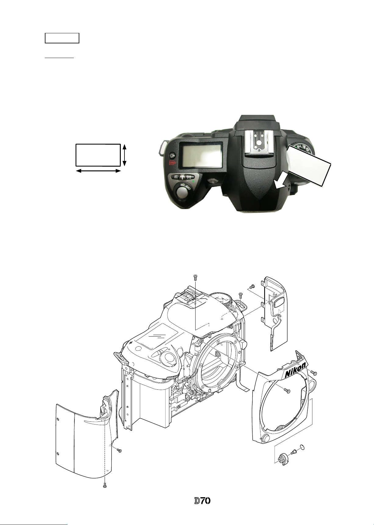
Approx.2cm
Approx. 4cm
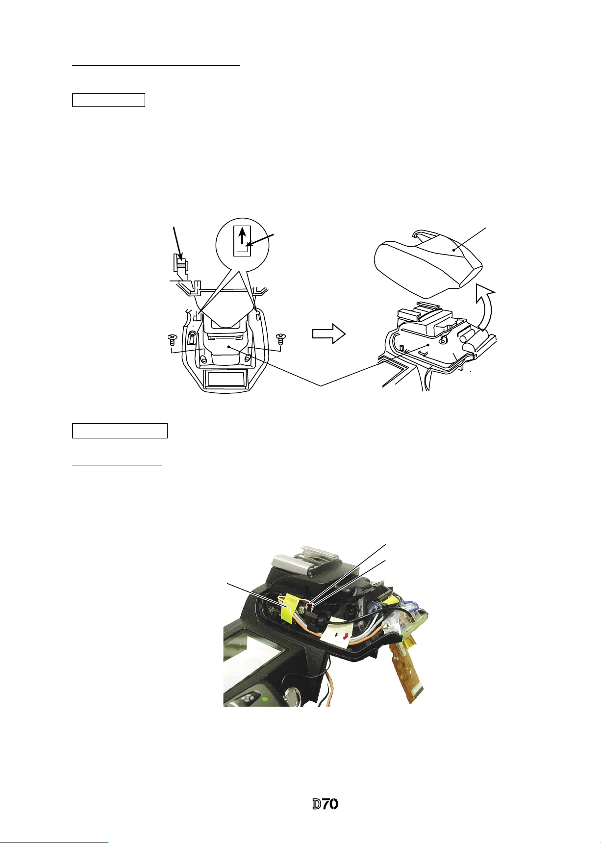
SB pop-up
・
Cut the tracing lm sheet, etc into the below size of piece. Then insert it into
the clearance of the top cover pop-up part as shown right, and pop it up by
sliding the sheet in the direction of the arrow.
#124
#659
#B26
#121
#684
#631
#611×2
#611×2
#776
#28
#608
#B24
Covers
・
First, remove the front cover (#B24).
VBA10401-R.3623.A
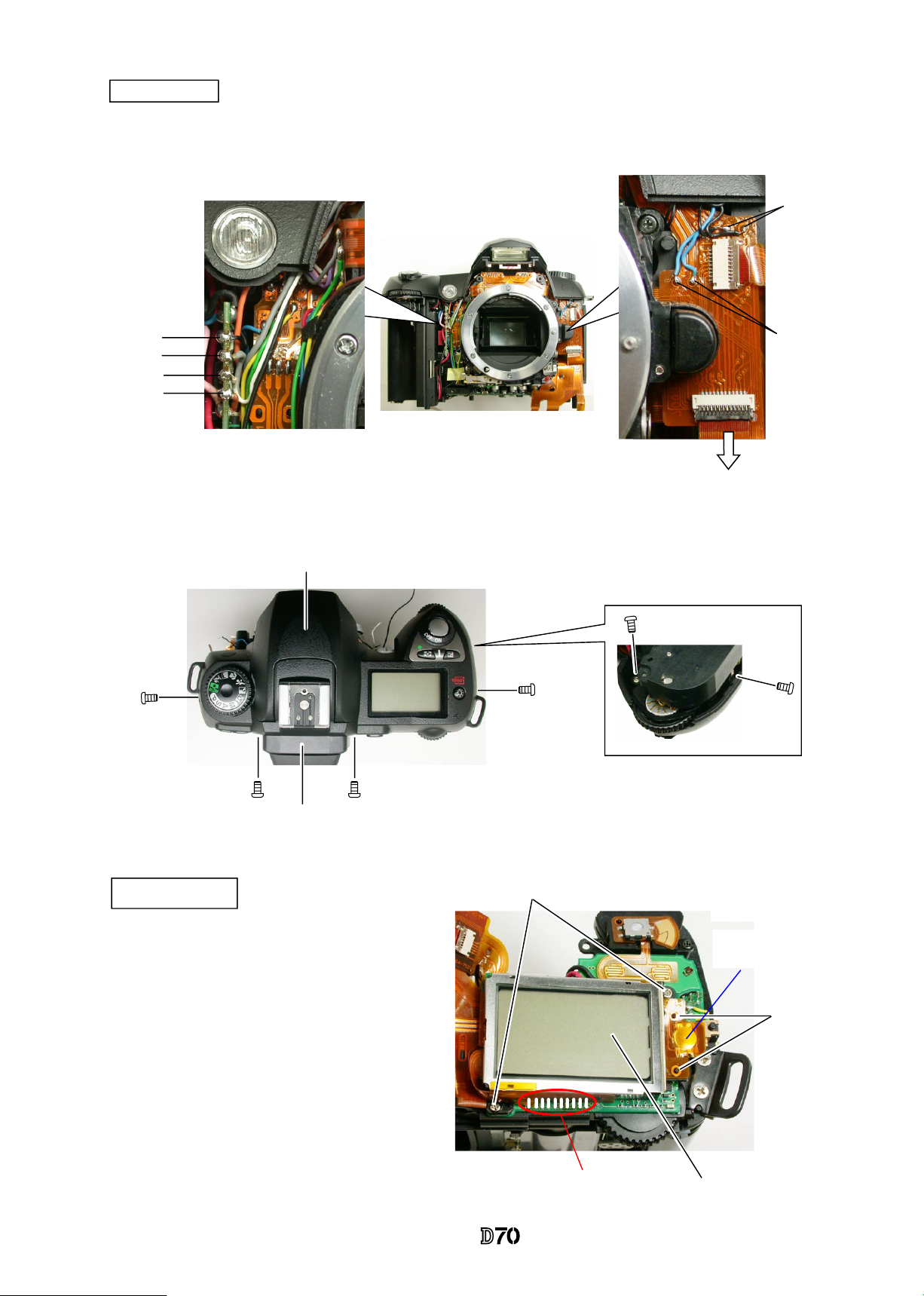
- D7 ・ -
・
Take out 6 screws to detach the top cover (#B23). The eyepiece frame (#B271) comes off, too.
・
Remove the solders of 8 wires.
・
Remove FPC#1026 from the connector.
#
642
#
618
#
618
#642
#635
#613
#B271
#B23
Blue×2
Black×2
#1026
Black
Gray
White
Orange
Top Cover
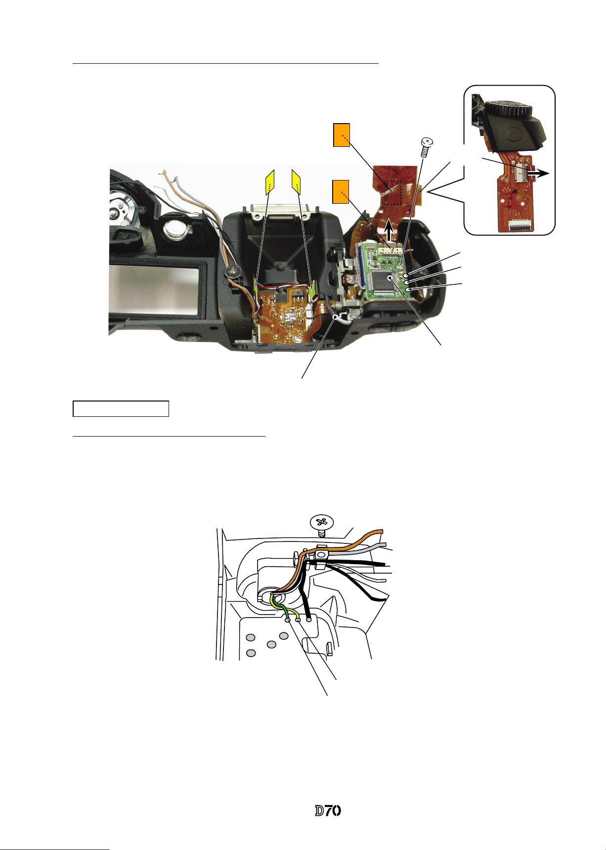
External LCD unit
Soldering bridges
#
613×2
Boss×2
#B2006
・
Remove soldering bridges.
・
Lift up the illuminator sw part
from the bosses(hub).
・
Take out 2 screws(#613) to detach
the External LCD (#B2006).
Illuminator sw part
: Lighting unit
: Main PCB
: Buzzer
Both-sided adhesive tape
on backside of FPC
VBA10401-R.3623.A
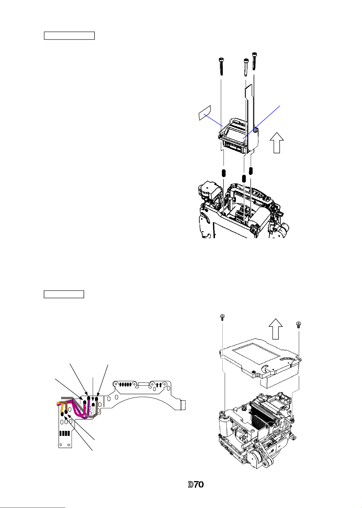
- D8 ・ -
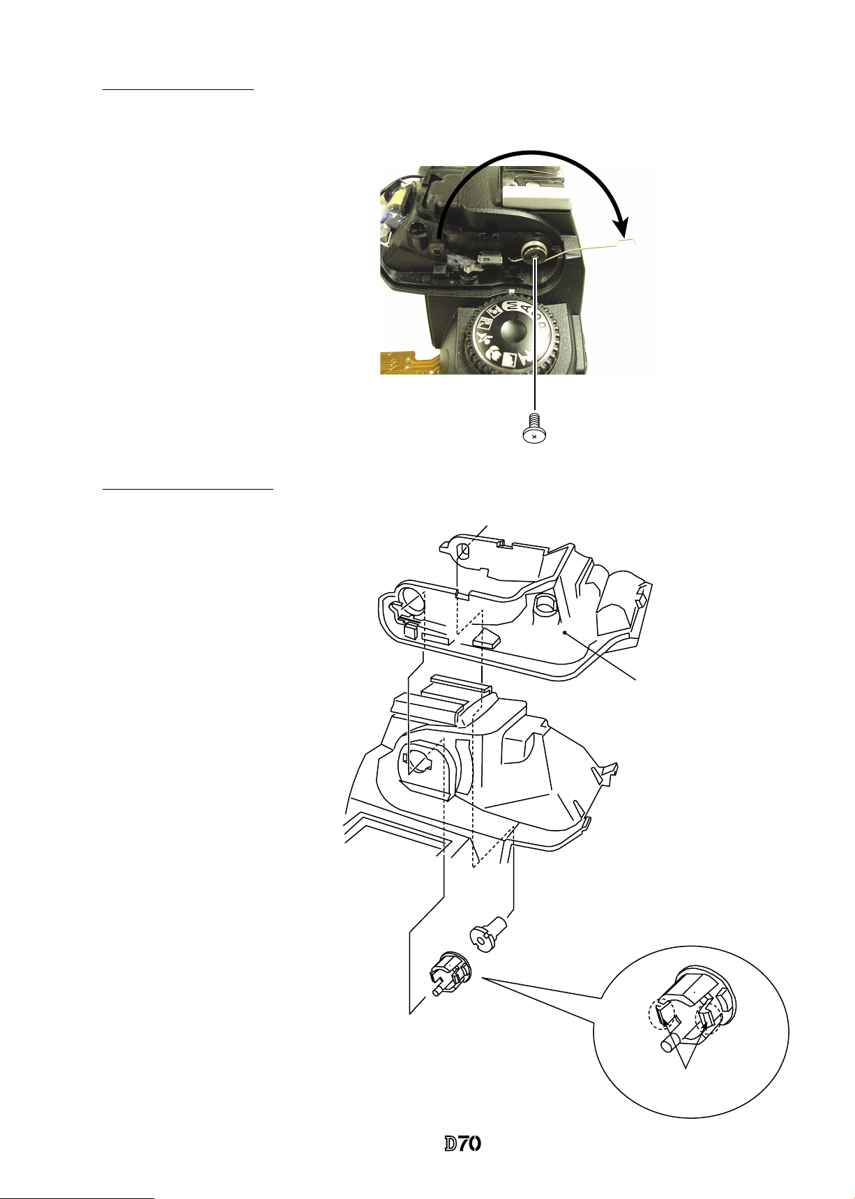
SB upper case
・
Press the pop-up lever A part of the top cover unit so that the built-in SB pops up.
・
Take out 2 screws (#631).
・
Push from beneath the hooking lever of the SB upper case as shown in Fig.1 . Then slide 2 hooks in the
direction of the arrow to remove the lever.
・
Deactivate pop-up of the SB lower case unit, and remove the SB upper case. (Fig.2)
Hooking lever
Fig.1
#631×2
Pop-up lever A part
SB lower case unit
SB upper case
Lighting unit PCB
Fig.2
Red: Lighting unit control PCB
White: Lighting unit control PCB
Tape (#709)
Unsolder Shield wires
Disassembly of Top cover unit
VBA10401-R.3623.A
- D9 ・ -
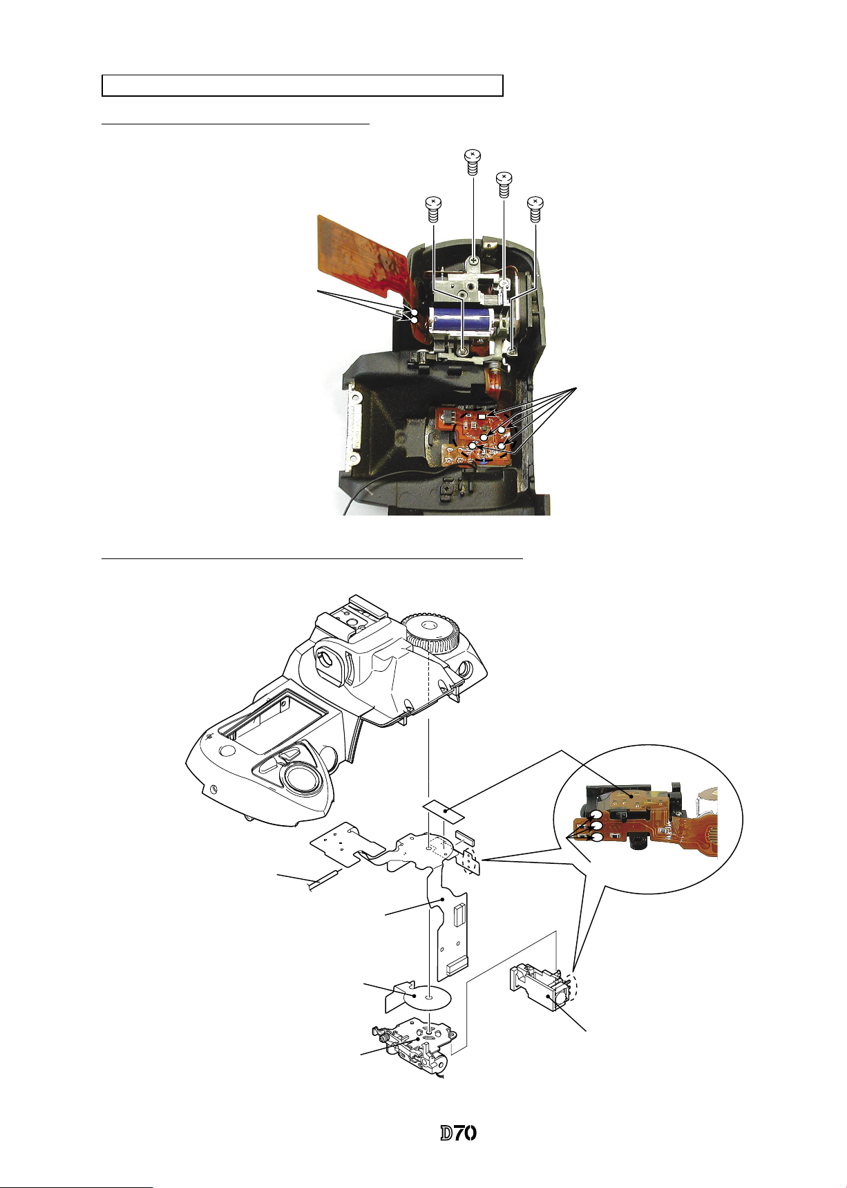
SB lower case unit
Remove Lighting unit control PCB, connection FPC, and Shield wires
#742
#607
#742
Tapes (#709×2)
Lighting unit control PCB
Black
Red
White
Shield wires
#646
Yellow: SB pop-up SW
Green: SB pop-up SW
Remove wire-holding screw/Unsolder wires
Connection
FPC
VBA10401-R.3623.A
- D10 ・ -
Remove Flash-up spring
Remove SB lower case unit
2 hooks
・Pull each wire out of holes.
・Losen 2 hooks of the collar (#308)
to remove it.
・Remove the SB case axle (#306).
・Detach the SB lower case unit
from the top cover.
・Unhook the Flash-up spring
(#305).
・Take out the screw (#646) and
remove the Flash-up spring
(#305).
#308
#306
#308
SB lower case unit
#646
#305
VBA10401-R.3623.A
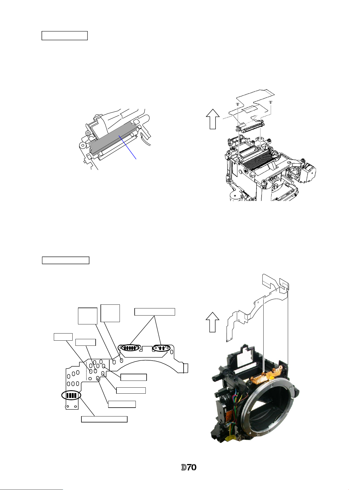
- D11 ・ -
Mode dial PCB unit, Remote control unit, Top cover FPC
Remove attaching screws, soldering bridges
#642
#635
#608×2
5 soldering bridges
Solder: Pop-up solenoid
Detach Mode dial PCB and Remote control unit from Top cover FPC
3 soldering bridges
Tape (#733)
Both-sided adhesive tape (#464)
Top cover FPC
Black: DC/DC PCB
Mode dial PCB
Remote control unit
Remote control unit
VBA10401-R.3623.A
- D12 ・ -
Mode dial unit, Release button, Power-supply dial, other small parts
Accessory shoe, Shoe mold unit, Outer LCD window, other small parts
#463
Mode dial unit
#142
#386
#339
#340
#340
#604×2
#381
#326
#766
#788
#347
#348
#640
#452
#453
#350
#351
#352
Power-supply dial
#387
Shoe base
Shoe mold unit
Outer LCD window
#318
#321
#322
#654×4
#336×2
#337×2
#338
#311×2
VBA10401-R.3623.A
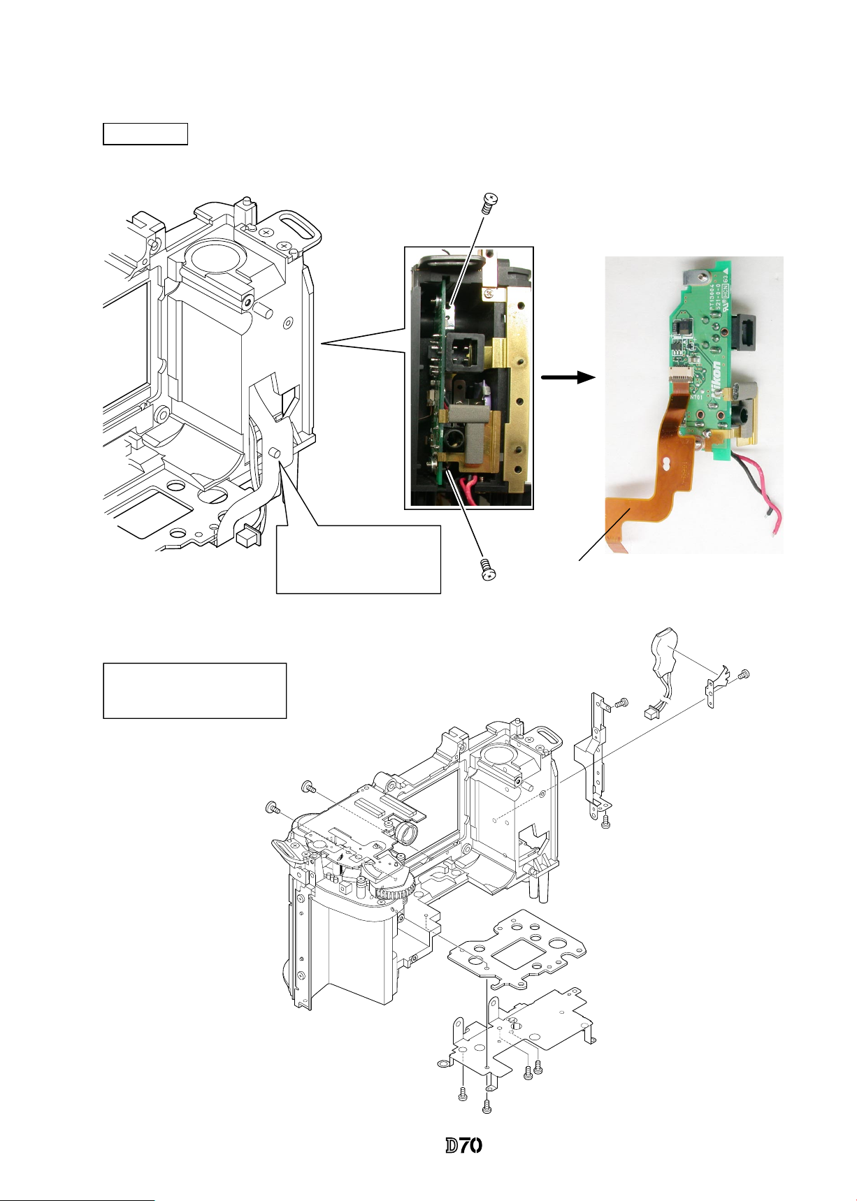
- D13 ・ -
Preview SW unit
Yellow
Green
Blue
#649
Preview SW unit
・
Remove the solders of 3 wires as shown right, and
take out the screw (#649) to detach the preview SW
unit.
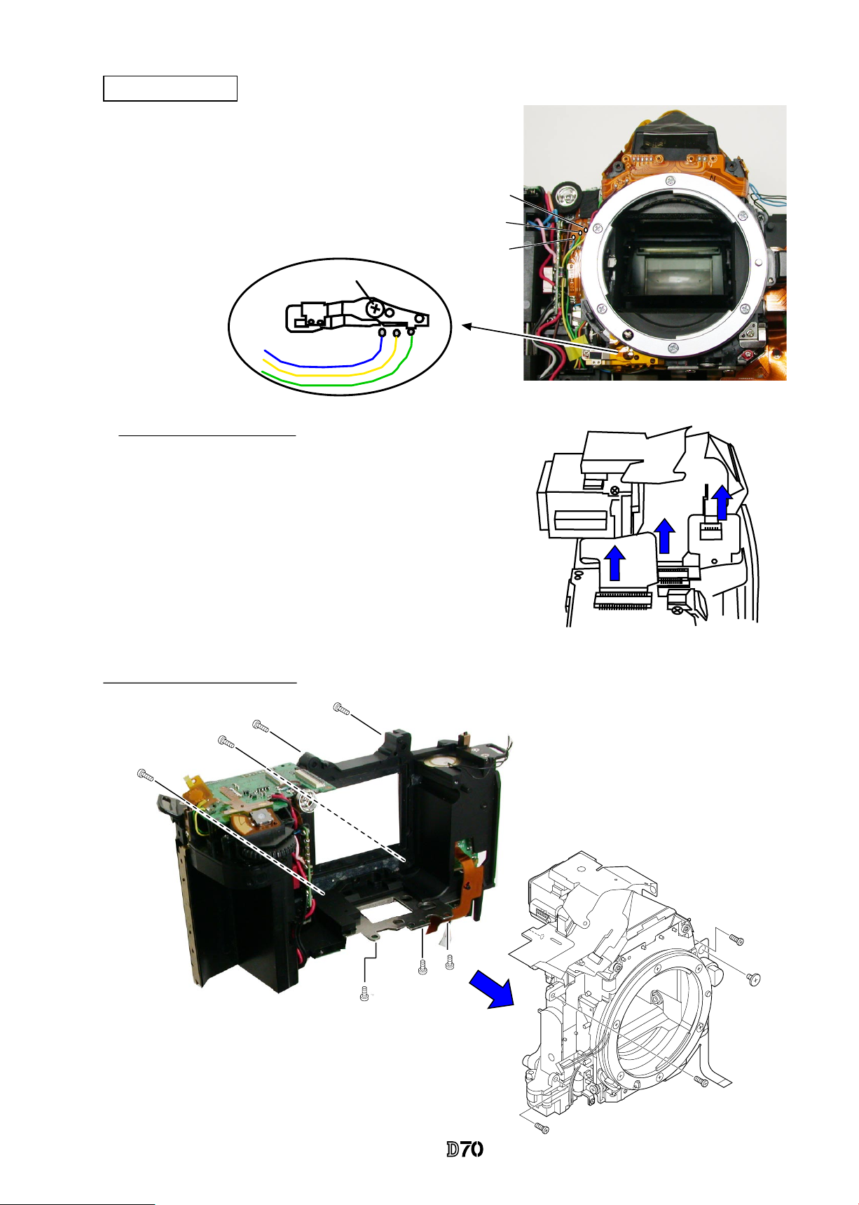
Separate Front and Rear bodies
Disconnect from Connectors
・
Remove the FPC
①
,
②
, and
③
from each connector in order.
①
②
③
#642×3
#646
#699×3
#634×4
Front body
Rear body
VBA10401-R.3623.A
- D14 ・ -
Disconnect Connectors
Eyepiece unit
Metering FPC unit
#631×2
・
Take out 2 screws (#631) so that the eyepiece unit
(#B261) with the Metering FPC unit(#B2008)
attached can be removed.
・
Disconnect the FPC①, ②, ③, and ④ from each connector in order.
#B2008
#B261
#B261
#B2008
#291×2
#290
Note: The eyepiece unit (#B261) and
Metering FPC
unit
(#B2008) is attached with the adhesive. Unless
replacement is necessary, do NOT disassemble them.
In case of disassembling them or turning the screws
(#291), AE CCD position adjustment (ref. Assembly
Chapter) is necessary.
①
#B2163
②
#1026
①
#B1008
④
#B1025
2. Front Body
VBA10401-R.3623.A
- D15 ・ -
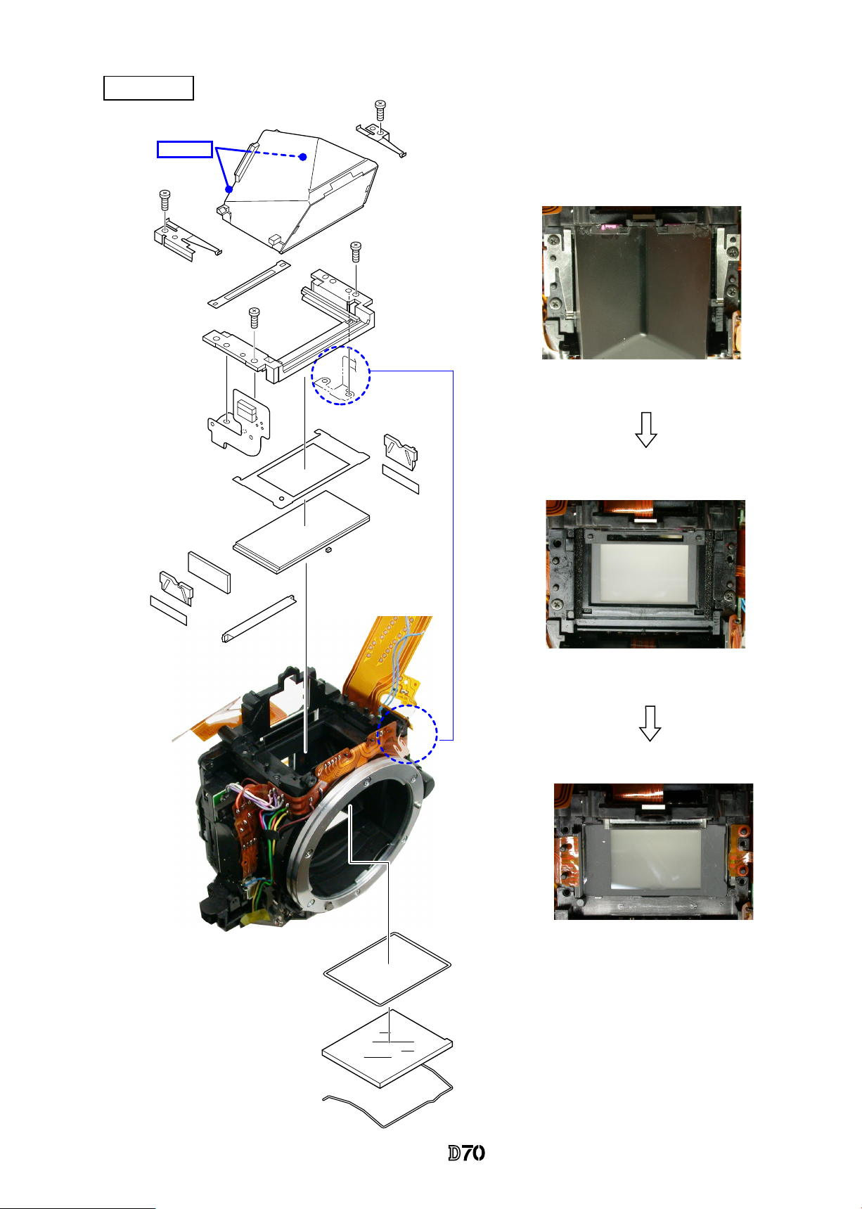
Penta unit
#284
#283
#G9
#1046
#B279
#280
#280
#B279
#282
#B1021
#278
#B277
#642×2
#B4
#255
#256
#642×2
#297
#G3
#739
Adhesive
VBA10401-R.3623.A
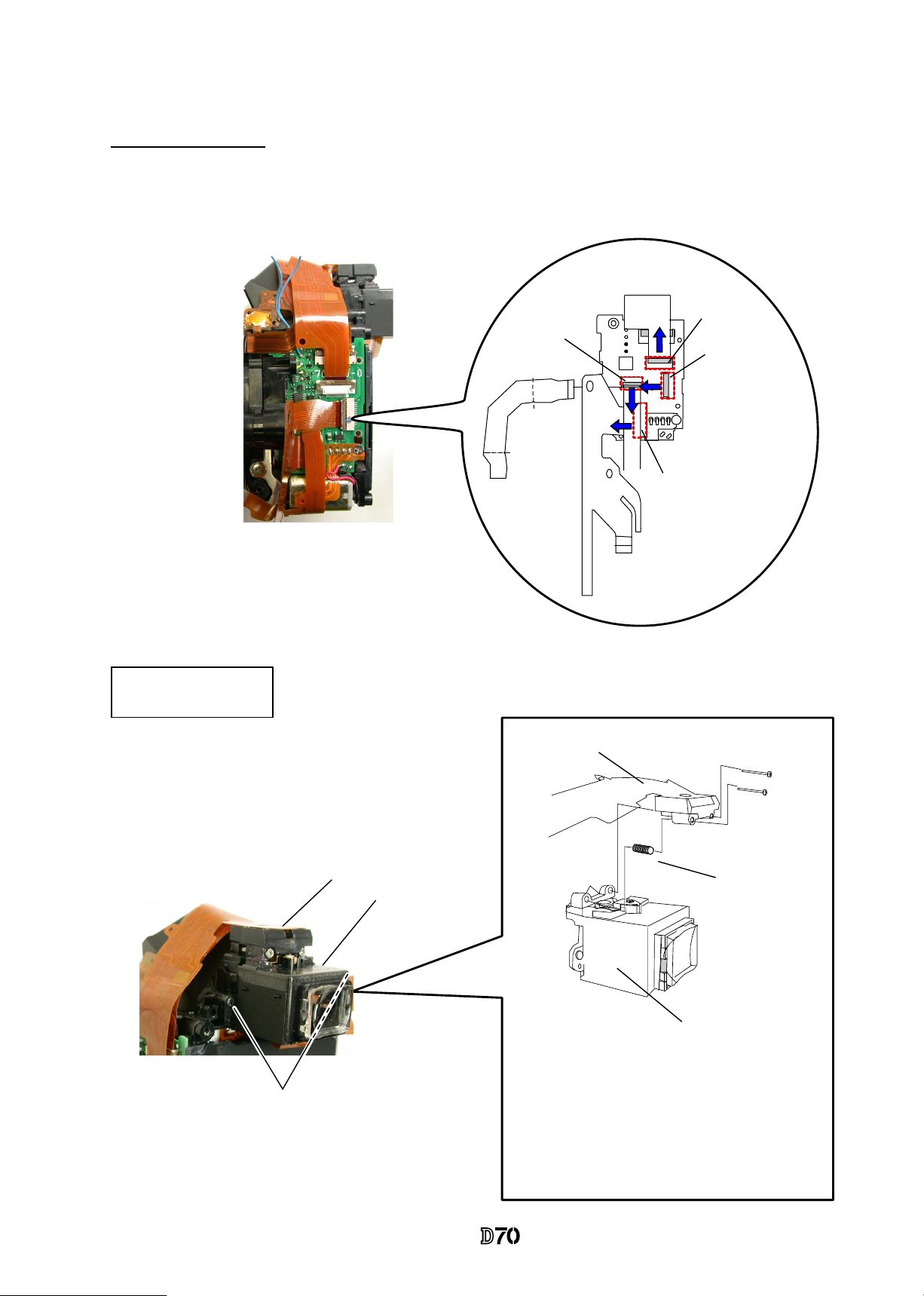
- D16 ・ -
・
Take out the screws (#658 and #632) to
detach the main PCB (#B2001) from the
front plate.
・
Remove the connection FPC (#B1004)
from the connector.
#B1004
#B2001
#632
#658
Connector (backside)
Front plate
・
Remove the front body FPC (#B1009) from the
connector.
・
Remove the solders and soldering bridges of 7
wires.
Blue×2:
Top cover FPC
Yellow:
A/M change sw
Red:AF motor
Black:AF motor
Soldering bridge
#B1009
Brown:DC-DC
Main PCB
Black:
A/M change sw
VBA10401-R.3623.A
- D17 ・ -
・
Take out 3 screws (#636) with Hexagonal
wrench, and remove the AF sensor unit
(#B2163).
・
3 springs (#170) come off, too.
AF sensor unit
#B2163
#
170×3
#
636×3
#728
Orange
Brown
Pink
Purple
White
Gray
・
Remove the solders of 6 wires.
・
Take out the screws (#607 and #627) to
detach the shutter unit (#B31).
#B31
#607
#627
AF sensor unit
Shutter unit
VBA10401-R.3623.A
- D18 ・ -
・
Remove the tape (#797).
・
Take out 2 screws (#653) to remove the inner LCD unit (#B2010).
Black
:
Fmin
Brown
:
Fmin
Soldering bridges
Green:SQ
Orange:SQ
Yellow:SQ
Blue:Mg
Red:Mg
Soldering bridges
#B2010
#653×2
Front body FPC
:
#1009
Inner LCD unit
Front body FPC
#797
VBA10401-R.3623.A
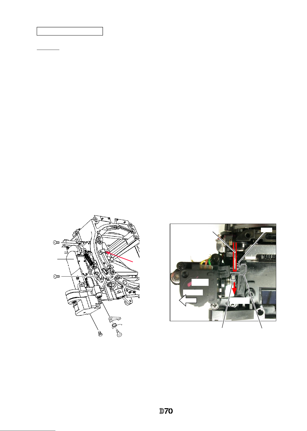
- D19 ・ -
Procedure
1.
Take out 3 screws (#642).
2. Remove the screw (#661), spring (#214) and lever (#254).
3.
Lock the mirror-up lever (#203) with the preview locking lever (#222).
4.
When the aperture lever is pressed down with nger, the aperture coupling lever (#207) moves in the
direction of arrow (①).
5.
In state of 4., remove the aperture control unit (#B241) by pulling it in the direction indicated by
arrow (②) while letting the arm (#B241) escape.
Arm of #B241
#207
#203
Lock #203 with this lever.
#222
Arrow
②
Arrow
①
#B241
#642×3
#254
#214
#661
#B241
Aperture lever
Front body viewed from the bottom
Aperture control unit
VBA10401-R.3623.A
- D20 ・ -
Soldering bridge of
#126 and #114
AF driving unit
Lens release button
Vertical lever
Horizontal lever
#B172
#637×2
#185
#122
#191
#630
#B116
#195
#193
#630
#B125
#126
#642
#607
#123
#B2113
#645×2
#113×3
#132
#135
#131
#114
Bayonet unit
A/M-change SW unit
#648×5
#660
#111
#115
#119
#642
#621
#189
・
First, remove the
horizontal lever
(#193).
VBA10401-R.3623.A
- D21 ・ -
Aperture lever unit
F-min Switch unit
Preview locking lever unit
#639
#208
#213
#375
#375
#203
#206
#209
#207
#210
#212
#205
#642
#134
#133
#222
#224
#223
#221
#202
#652
#624
#190
#239
#238
#234
#199
#199
#B2231
#236
Mirror unit
・
Note that 2 pins (#199) and the pin (#236)
are attached with the Super X.(C-8008B)
VBA10401-R.3623.A
- D22 ・ -
IF-PCB
・
Take out 2 screws (#610) to remove the IF-PCB from the rear body.
#610×2
Rear body
IF-PCB
Remove the connection FPC
(#1061) from the rear body
pin.
#75
#610×2
#635×4
#B103
#66
#633×2
#1059
#73
#691
#1061
Bottom Base unit
Secondary battery unit
3. Rear body
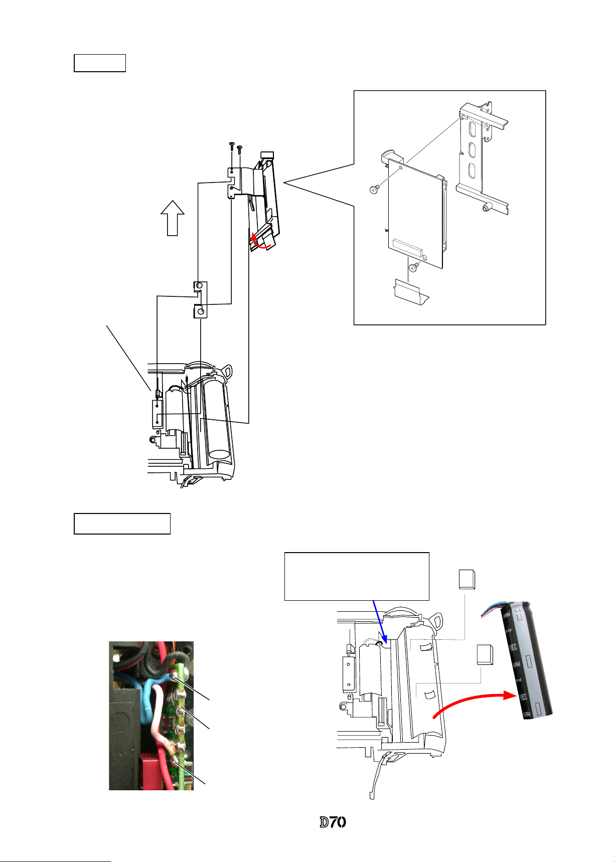
VBA10401-R.3623.A
- D23 ・ -
#1064
#663×2
#B1034
#B467
CF-PCB
・
Take out 2 screws (#635) to remove the
CF-PCB and CF ground plate (#469).
Remove FPC by pulling
aside in the direction of
the arrow.
#635×2
CF-PCB
#467
Rear body
Main condenser
Remove the 2 wires (pink and blue) as
described left while setting aside by
passing them through this hole.
#754×2
Remove the solders of 2 wires (pink
and blue) on the SB-PCB of the front
of the rear body.
SB-PCB
Blue:Main condenser
Pink:Main condenser
#1043
 Loading...