

Page 1

M349 E 06.8.NF.1
*M349EN01*
INTENSILIGHT
C-HGFI / C-HGFIE
Precentered Fiber Illuminator
Instructions
Page 2

Page 3

Introduction
Thank you for purchasing the Nikon product.
This instruction manual is written for the users of the Nikon "C-HGFI Intensilight (Precentered Fiber Illuminator),"
manual operation type, or the "C-HGFIE Intensilight (Precentered Fiber Illuminator)," motorized operation type.
To ensure correct usage, read this manual carefully before operating the product.
• Copyright laws prohibit the copying of this manual, in whole or in part, without written permission from Nikon.
• The contents of this manual are subject to change without notice.
• Although every effort has been made to ensure the accuracy of this manual, errors or inconsistencies may remain. If
you note any points that are unclear or incorrect, please contact your nearest Nikon representative.
• Some of the products described in this manual may not be included in the set you have purchased.
• Be sure to read the manuals for any other products that you are using with this system (the microscope, epi-fl
illuminator, or so on).
• If the products are used in a manner not specified by the manufacturer, the protection provided in the products may be
impaired.
1
Page 4
Safety Precautions
WARNING and CAUTION symbols used in this manual
Although Nikon products are designed to provide the utmost safety during use, incorrect usage or failure to follow the
safety instructions provided may cause personal injury or property damage. Damage or injury that may occur due to
mishandling is unwarranted. To ensure correct usage, read the instruction manual carefully and thoroughly before using
the product. Do not discard the manual; keep it handy for easy reference.
Safety instructions within this manual are described with the following symbols to highlight their importance. For your
safety, always follow the instructions accompanied by these symbols.
Symbol Meaning
Disregarding instructions accompanying this symbol may lead to serious injury or
WARNING
CAUTION
death.
Disregarding instructions accompanying this symbol may lead to injury or property
damage.
Meaning of the symbol used on the product
The symbol appearing on the product indicates the need for caution at all times during use.
Always refer to the instruction manual and read the relevant instructions before manipulating any part to which
the symbol has been affixed.
Symbol Meaning
Caution for heat
The symbols are labeled near the lamp replace cover on the top of the product and above the air vents
on the back of the product. The symbols indicate that the lamp and the surrounding parts become
extremely hot while the lamp is lit and immediately after it is turned off and that extremely hot air flows
from the air vents while the lamp is lit. Follow the cautions below to avoid burn injury and to prevent
fire.
• Never touch the lamp and the surrounding parts while the lamp is lit or within 30 minutes after
the lamp is turned off.
• Keep hands away from the air vents when the lamp is lit. Do not block the airflow from the air
vents.
• Allow the lamp and surrounding parts to cool sufficiently before replacing the lamp.
• Do not allow walls, curtains, or papers to contact the product.
• Do not allow cloth, paper, or highly flammable volatile materials, such as gasoline, benzine, paint
thinner or alcohol, to come near the lamp or the surrounding area while the lamp is lit or within 30
minutes after switching off the power.
• Do not draw any power cord on the product body.
CAUTION
The symbol is labeled near the lamp replace cover on the top of the product and above the air vents on
the back of the product. The symbol indicates the following cautions:
• Before changing the lamp, turn off the product and pull out the power cord from the wall outlet.
Before opening the lamp replace cover, check that the power switch is set to the "0" side (the "|"
side is Off and the "0" side is On) and that the power cord is disconnected with the wall outlet.
• Before changing the lamp, read the instruction manual carefully.
When replacing the lamp, refer to page 14, "Installing/replacing the mercury lamp" and be careful
for safety.
2
Page 5
Safety Precautions
1. Intended application
WARNING
This product must be used only for microscopic observation. Do not use this product for other purpose.
2. Do not disassemble
Disassembling this product may result in electric shock or other hazards. Malfunctions and damage due to
disassembling are unwarranted. Never attempt to disassemble any part other than the parts described in this
manual. If you experience problems with this product or the microscope system, contact your nearest Nikon
representative.
3. Power supply ratings and power supply cords
The power supply circuit in this product is designed for AC power of 100 to 240 VAC and 50/60 Hz. Before
connecting the power cord, check that the AC power supply to be used conforms to the voltage and frequency
described above.
Always use power cords that satisfy local safety regulations. Always use three-pole grounded outlets.
For specifications of the power cord, refer to "VII. Specifications."
4. Use the specified mercury lamp
Use the specified mercury lamp. If a wrong lamp is used, it may cause a malfunction, a fire, or an electric
shock.
• Mercury lamp: Nikon C-LHGFI HG lamp
For details about the lamp handling, refer to page 7, "3. When handling mercury lamp" and follow the
instructions.
5. Turn off the power before assembling and connecting the illuminator or replacing
lamps.
To prevent an electric shock and fire, turn off the power by pressing down the "0" side of the power switch and
disconnect the power cable from the outlet before operations such as assembling the illuminator or replacing
lamps.
6. Heat from the light source
The symbol of is attached near the lamp replace cover on the top of the product and above the air vents
on the back of the product. The symbol indicate that the lamp and the surrounding parts become extremely hot
while the lamp is lit and immediately after it is turned off and that extremely hot air flows from the air vents
while the lamp is lit. Follow the cautions below to avoid burn injury and to prevent fire.
• Never touch the lamp, its surrounding parts, and the air vents while the lamp is lit or within 30 minutes after
the lamp is turned off.
• Keep hands away from the air vents when the lamp is lit. Do not block the airflow from the air vents.
• Allow the lamp and surrounding parts to cool sufficiently before replacing the lamp.
• Do not allow walls, curtains, or papers to contact the product.
• Do not allow cloths, papers, or highly flammable volatile materials, such as gasoline, benzine, thinner or
alcohol, to come near the lamp, its surrounding parts, or the air vents while the lamp is lit or within 30
minutes after the lamp is turned off.
• Do not draw any power cord on the product body.
3
Page 6
Safety Precautions
7. Ultraviolet light
WARNING
A mercury lamp radiates ultraviolet light that is harmful to the eyes and skin when the lamp is turned on. Direct
viewing of light from the lamp may result in snow blindness at a light case or blindness at the worst case. To
prevent injury, follow the guidelines below:
• Use a filter or a collector lens with UV cut specification in the optical path of the microscope or the
illuminator unless UV excitation light is necessary for epi-fl microscopy.
• When performing the epi-fl microscopy by using the UV excitation light, attach the filter cube dedicated to
the UV excitation light. And then, if you must see the objective or its surroundings, be sure to see through
the ultraviolet light shield.
8. For safety
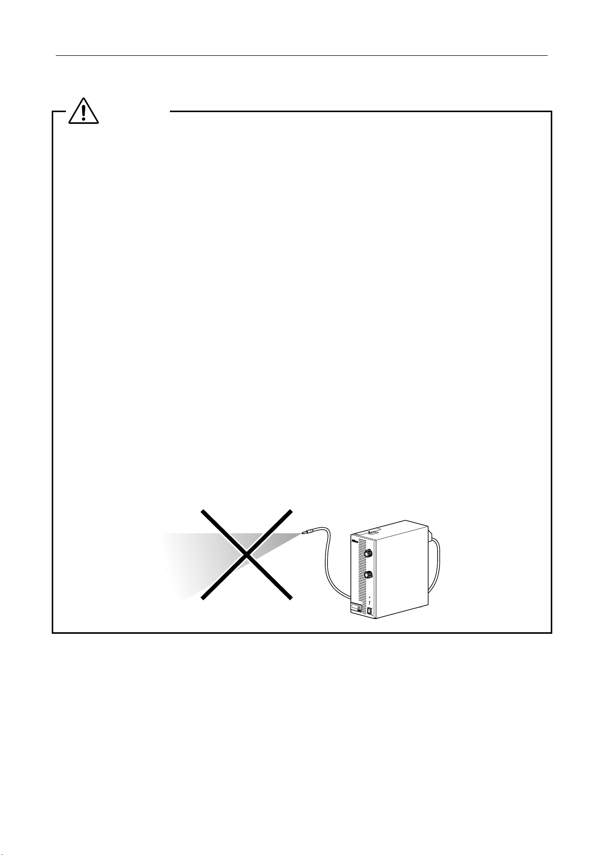
While the mercury lamp is lit, it emits the very strong light beam, which includes ultraviolet light and is harmful to
human eyes and skin, through the light guide fiber connected to the product. The beam is so intense that there
are possibilities of danger, such as fire or burn, and especially, leading to blindness if one sees the beam directly.
In order to avoid an accident, the following instructions must be always observed:
• Attach the light guide fiber to the microscope before turning on the lamp.
While the mercury lamp is lit, it is strictly prohibited that removing the light guide fiber from the microscope
or looking into the light guide fiber tip.
• Before removing the light guide fiber from the product, turn off the lamp.
Also, before removing the light guide fiber from the microscope, turn off the lamp.
• Before turning on the power of the product, connect the light guide fiber correctly.
If the light guide fiber is not connected correctly and the power of the product is turned on, the connection
part of the light guide fiber becomes hot and it may cause a burn injury.
IN
T
E
N
S
IL
IG
H
T
C
HGFI
SHUTTER
ND
8
4
16
2
32
1
LAMP
RUN TIME hrs.
POWER
4
Page 7

Safety Precautions
9. Mercury lamp (HG lamp) burst and gas leak
WARNING
If the lamp is scratched or used over the life, the lamp may burst or gas may leak from the lamp.
If the lamp bursts, the broken glass may be scattered and hurt human beings and/or the product. Besides, the
gas inside the lamp (vaporized mercury and Ar inert gas) is released into the air bringing about the danger of
inhaling the gas. To avoid these dangers and to cope effectively with these abnormal situations, please read
the articles below before using the product. For details about the lamp handling, refer to page 7, "3. When
handling mercury lamp" and follow the instructions.
• The inorganic mercury is said to be less harmful and less absorbed by human beings than the organic
mercury (methyl mercury), but sill is harmful and an utmost care is needed in handling them.
• If the lamp bursts or the gas leaks, all the personnel must immediately leave the room so as not to inhale
the mercury vapor. Further, thoroughly ventilate the room for at least 30 minutes.
• If you happen to inhale the mercury vapor, immediately rinse your mouth and throat with a plenty amount
of water. If mercury or mercury vapor contacts on your skin or gets into your eyes, wash it off with a plenty
amount of water likewise. If you feel sick, or notice any sign of illness, please at once consult your doctor.
• Before cleaning up the mess, wait till the lamp and the surrounding parts cool down.
• To gather the scattered liquid mercury, use a special material for absorbing the mercury (available from vendors
handling experimental materials). Dispose of them as the special industrial waste or dispose of them according
to the laws or rules of your local waste system.
• Pick up the broken pieces of glass with the greatest care so as not to cut your fingers. Put the broken
pieces of glass in a hard container and dispose of them as the special industrial waste or dispose of them
according to the laws or rules of your local waste system.
• Because safety is a top priority in the design of Nikon products, the hazards described above should not
pose any danger as long as you heed all of the warnings and cautions in the manuals and use the system
only for its intended purpose. However, the hazards described above could lead to an accident if you fail to
heed all of the warnings and cautions in the manuals, if you strike the system, or if you attempt to
disassemble the system. Therefore, always be sure to heed all of the warnings and cautions.
• If the lamp bursts, contact your nearest Nikon representative immediately. Never continue to use the
product in "as is" condition, because some glass shreds may remain in the product.
5
Page 8
Safety Precautions
CAUTION
1. Do not wet the product or allow foreign matter to get inside
If the product gets wet, a short circuit may cause malfunction or abnormal heating of the product. Similarly, if
foreign matter gets inside, a short circuit may occur. If you accidentally spill water on the product, immediately
turn off the power switch (flip it to the "0" side) and unplug the power cord from the wall outlet. (Take care not
to touch the cord with wet hands at this time.) And then, wipe off the water with a dry cloth.
Check the connectors such as AC inlet on the back of the product. If you find any moisture, wipe them away.
If any liquid or foreign matter gets inside, do not use the equipment, but contact your nearest Nikon
representative.
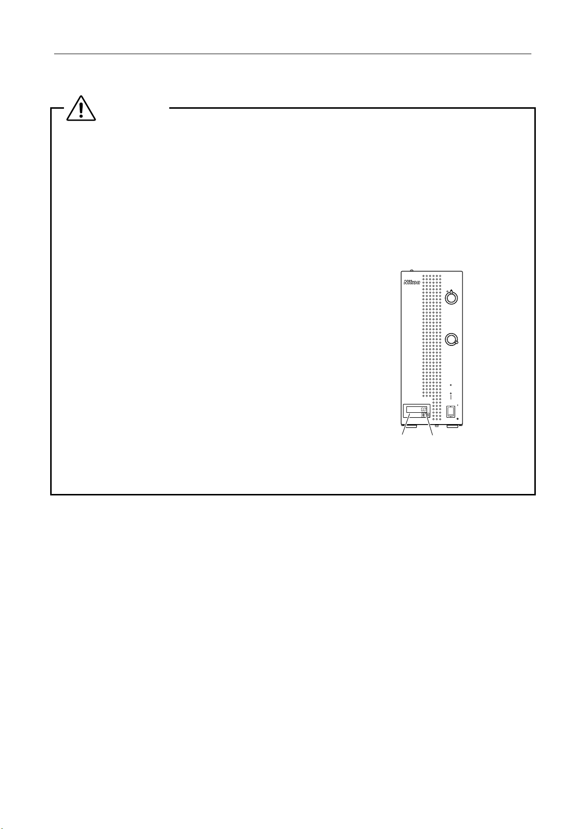
2. Mercury lamp life expectancy
The average life expectancy of a Nikon HG lamp C-LHGFI is 2000
hours. Exceeding 2000 hours of use may lead to an accident such
as burst of the lamp. Always replace with a new lamp once the
RUN TIME counter reading exceeds "2000.0." (Hour meter reads
2000.0 which equals 2000 hours.)
INTENSILIGHT
C-HGFI
SHUTTER
ND
4
8
2
16
1
32
After replacing a lamp, be sure to reset the RUN TIME counter
display to "000.0" by pressing the reset button. The RUN TIME
counter shows the total accumulated time that the lamp has been
RUN TIME hrs.
LAMP
POWER
lit. Do not press the reset button except when replacing with a new
lamp. Doing so will cause you to lose track of the accumulated time
of operation.
* If the lamp bulb becomes noticeably blackened, replace with a
new lamp regardless of the accumulated time of operation.
RUN TIME Hrs.
counter
Front view (C-HGFI)
Reset button
6
Page 9

Safety Precautions
3. When handling mercury lamp
CAUTION
When handling the mercury lamp, follow the guidelines given below and take enough care in order to avoid
accidents and injury caused by the lamp burst.
• Do not subject the lamp to shock or vibration.
• Do not allow dirt or fingerprints to get on the inner surface of the reflector.
• Do not scratch the inner surface of the reflector.
• Do not exert excessive force on the electrode or the reflector. (Particularly when installing the lamp into
the socket.)
• When attaching the lamp into the lamp holder, insert the lamp as far as it goes and fix the lamp with the
wire form hooked.
• When connecting the lamp cord, securely insert the connector.
• Take care not to cut your hands when cleaning up the glass shreds of the burst lamp.
• Do not use a lamp beyond its life expectancy.
• Store lamps in a proper storage environment. Storage of the lamp in an inappropriate environment may
cause the lamp to burst.
<Storage conditions>
Temperature: -20 to +60ºC
Humidity: relative humidity 90% maximum (no condensation)
Miscellaneous: Do not subject the lamp to vibration or shock as these may cause the lamp to burst or
shorten its life expectancy.
• Do not break the used up lamps, but dispose of them as the special industrial waste or dispose of them
according to the laws or rules of your local waste system.
<Supplemental notes>
• If fingerprints or dirt stuck on the reflector surface, wipe them with a piece of soft, clean cotton cloth or
gauze lightly dampened with absolute alcohol.
• The glass shards should be placed in a hard container for disposal.
• If you notice an abnormality while using a lamp, immediately stop operation and contact your nearest
Nikon representative.
• The product is designed to keep the glass shreds within the product even if the lamp bursts during
illumination (when a burst occurs inside the product).
• If the lamp bursts during illumination, wait till the periphery of the lamp cools sufficiently before cleaning
up.
• For details on installing a lamp, see page 14, "Installing/replacing the mercury lamp."
4. Ozone
It is assumed that a small amount of ozone is produced during mercury lamp illumination. Since ozone can
irritate the mucous membranes of the eyes and nose upon contact, be sure to provide sufficient ventilation
while the lamp is illuminated. Never inhale the air exhausted from the mercury lamp directly, or never let the
same air hit your face.
7
Page 10

Safety Precautions
Notes on handling the product
1. Handle with care
This product is a precision optical instrument. Make sure that the product is not subject to shock; handle the
product gently. Also be sure to handle cables with care. Light guide fiber, in particular, must not be bent or pulled
with excessive force, to prevent failure, malfunction, or broken wires.
2. Installation conditions
If this product is used or stored under unsuitable conditions, it may get damaged or loose accuracy. Consider the
following factors when arranging an installation location or storing the product:
• Use the product at ambient temperatures of between 0 and +35ºC and in conditions of relative humidity 85% or
less (no condensation) in a room. Store the product at ambient temperatures of between -20 to +60ºC and in
conditions of relative humidity 90% or less (no condensation). Using or storing the product in hot, humid
locations may result in mold formation or condensation on lenses, performance degradation, or malfunctions.
• Install the product in a surrounding clear area of 10 cm or more (20 cm or more for the rear). In particular, do
not block the airflow form the cooling fan and the air vents on the back of the product. Do not place any
obstacle near the cooling fan and the air vents.
• Do not place anything on the product.
• Do not install or use the product in a closed place such as a shelf or a locker.
• Install the product in a place with little dust and dirt.
• Install the product in a place with little vibration.
• Install or store the product on a sturdy horizontal desk or table that is able to bear the weight of the system.
• During storage, cover the product so that it does not gather dust.
• Arrange a layout that allows easy removal of the power cord from the inlet of the product in the event of an
emergency.
8
Page 11

Contents
Introduction .........................................................................................................................................................................1
Safety Precautions .............................................................................................................................................................. 2
WARNING and CAUTION symbols used in this manual ....................................................................................... 2
Notes on handling the product............................................................................................................................... 8
I Names of Component Parts ....................................................................................................................................... 10
C-HGFI Precentered fiber illuminator (manual operation type) .........................................................................10
C-HGFIF15/C-HGFIF30 HG fiber...................................................................................................................... 10
C-HGFIE Precentered fiber illuminator (motorized operation type)................................................................... 11
C-HGFIE-C HG controller ................................................................................................................................. 11
II Connecting the Equipment ......................................................................................................................................... 12
Connecting the light guide fiber ........................................................................................................................... 12
Power code connection .......................................................................................................................................13
Connecting the HG controller (only for the C-HGFIE).......................................................................................... 13
Affxing the luminous sticker (only for the C-HGFIE) ............................................................................................ 13
Connecting the RS-232C cable (only for the C-HGFIE)....................................................................................... 13
Connecting the external shutter control signal I/O cable (only for the C-HGFIE)................................................. 13
III Instructions for Use..................................................................................................................................................... 14
Installing/replacing the mercury lamp ..................................................................................................................14
Turning on/off the lamp........................................................................................................................................ 16
Opening/closing the shutter .................................................................................................................................17
Controlling the lamp............................................................................................................................................. 17
Operating the HG controller (only for the C-HGFIE) ............................................................................................18
Operating the RUN TIME hrs. counter................................................................................................................. 18
IV Troubleshooting.......................................................................................................................................................... 19
Safety protection circuit .......................................................................................................................................20
V Care and Maintenance ...............................................................................................................................................21
Cleaning optical parts .......................................................................................................................................... 21
Cleaning painted components .............................................................................................................................21
Cleaning the fan................................................................................................................................................... 21
Battery for the RUN TIME hrs. counter ................................................................................................................ 21
Storage ................................................................................................................................................................ 21
Periodical inspection (charged)............................................................................................................................ 21
VI Controlling by External Equipment (C-HGFIE) ........................................................................................................... 22
RS-232C interface ...............................................................................................................................................22
Overview..................................................................................................................................................... 22
Command format ........................................................................................................................................ 23
Communication sequence .......................................................................................................................... 24
Communication buffer................................................................................................................................. 24
Communication command .......................................................................................................................... 25
Shutter control by external signal......................................................................................................................... 28
VII Specifications ............................................................................................................................................................. 29
VIII Connection to a Microscope ....................................................................................................................................... 31
9
Page 12

r
A
A
I
Names of Component Parts
For connecting this equipment to the microscope and illumination system, refer to "II. Connecting the Equipment" on
page 12.
For attaching and replacing lamps, refer to "Installing/replacing the mercury lamp" on page 14.
C-HGFI Precentered fiber illuminator (manual operation type)
The knobs on the front panel enable the shutter open/close control and the six step light control.
Lamp replace cover plate
SHUTTER knob (shutter
open/close control knob)
ND select knob (six step
light control knob)
RUN TIME hrs.
counter (hour mete
of lamp)
Reset button
INTENSILIGHT
C
-
HGFI
16
32
RUN TIME hrs.
Power switch
SHUTTER
ND
8
LAMP
POWER
<Rear view>
ir vents
Light guide fiber
This device complies with Part 15
of the FCC Rules. Operation is subject
to the following two conditions
:
(1) This device may not cause harmful
interference, and (2) this device must
4N75
TÜV
accept any interference received,
INSPECTION
Rheinland
geprüfte
Sicherheit
Product Safety
EQUIPMENT
including interference that may
cause undesired operation.
This Class A digital apparatus
complies with Canadian ICES-003.
Cet appareil numérique de la
classe A est confirme à la norme
NMB-003 du Canada.
AC-IN 100-240~
50/60Hz 2.0A
4
2
1
C-HGFI
JAPAN
870001
connection port
Cooling fan
C inlet
LAMP indicator (yellow)
POWER indicator (green)
C-HGFIF15/C-HGFIF30 HG fiber
Source side connector (to be
connected to the light source)
Emission side tip (to be connected
to the microscope)
10
Cable length
・C-HGFIF15: 1.5 m
・C-HGFIF30: 3.0 m
Page 13

I Names of Component Parts
r
A
C-HGFIE Precentered fiber illuminator (motorized operation type)
This type of illuminator has motorized shutter open/close function and light control function. You can operate the
shutter open/close control and the light control by using the C-HGFIE-C HG controller. Also, you can operate them
by external equipment through RS-232C interface and shutter control signal I/O connector.
RUN TIME hrs.
counter (hour mete
Reset button
Lamp replace cover plate
INTENSILIGHT
C
-
HGFIE
RUN TIME hrs.
of lamp)
Power switch
LAMP
POWER
LAMP indicator (yellow)
POWER indicator (green)
<Rear view>
ir vents
Light guide fiber
connection port
AC-IN 100-240~
50/60Hz 2.0A
This device complies with Part 15
of the FCC Rules. Operation is subject
:
to the following two conditions
(1) This device may not cause harmful
interference, and (2) this device must
4N75
TÜV
accept any interference received,
INSPECTION
Rheinland
geprüfte
Sicherheit
Product Safety
EQUIPMENT
including interference that may
cause undesired operation.
-
232C
RS
This Class A digital apparatus
complies with Canadian ICES-003.
Cet appareil numérique de la
classe A est confirme à la norme
NMB-003 du Canada.
SHUTTER
C-HGFIE
JAPAN
870001
REMOTE
Cooling fan
RS-232C connector
AC inlet
Shutter control signal I/O connector
Remote controller connector
C-HGFIE-C HG controller
This is the specially-designed remote controller for the C-HGFIE.
Indicator brightness select
OPEN indicator (lit when the
LAMP indicator (lit when
the lamp turns on)
SHUTTER button
(toggles between open
and close when pushed)
ND select buttons
(six steps, up/down)
shutter opens)
LAMP OPEN
32 16 8 4 2 1
SHUTTER
ND
C-HGFIE
HG CONTROLLER
switch (changes indicator
brightness in three steps)
POWER
POWER indicator (lit
when the power is on)
ND indicator
Connector
L
A
M
P
O
P
E
N
P
3
O
2
W
E
R
1
S
68
H
U
T
T
E
R
4
N
D
2
1
H
G
C
-
C
H
O
G
N
F
T
I
E
R
O
L
L
E
R
11
Page 14

II
Before connecting the illuminator, read all precautions written in "Safety Precautions" found at the beginning of this
instruction manual.
For attaching and replacing lamps, refer to "Installing/replacing the mercury lamp" on page 14.
• Required tool: M2.5 Hex driver (or hex key)
Connecting the Equipment
Connecting the light guide fiber
When the lamp is lit, illumination light including ultraviolet light harmful to skin and eyes is emitted from the
tip of the light guide fiber.
The light guide fiber must be connected to the microscope or illuminator whenever the lamp is lit. And if the
light guide fiber is removed from the microscope, be sure the lamp is turned off.
Do not remove the light guide fiber when the lamp is lit. Do not take a look at the light guide fiber tip while
the lamp is lit.
1
WARNING
Attach the bayonet mount of the fiber adapter to the
connection port of the microscope or illuminator to be
used.
Bayonet
3
ring
Fiber adapter
(C-HGFIA, option)
Rotate the bayonet ring to the (
positioning pin to the groove and connect them (
rotate the bayonet ring to the (
position.
Insert the emission side tip of the light guide fiber into the
2
fiber adapter C-HGFIA connection port up to the limited
position. And then, tighten the clamp screw.
Use a hex driver to tighten the clamp screw.
Insert the source side connector of the light guide fiber
3
into the light guide fiber connection port of the illuminator
up to the limited position. And then, tighten the clamp
screw.
Use a hex driver to tighten the clamp screw.
* For safety, this illuminator has a mechanical shutter in the
light guide fiber connection port. When the source side
connector of the light guide fiber is detached, the
mechanical shutter closes together.
) direction. Align the
) direction up to the limited
). Then,
1
Clamp screw
2
Clamp screw
Emission side tip
Source side
connector
Light guide fiber connection port
Connection to a microscope
Some microscope systems connect the light guide fiber to an epi-fl
attachment or epi illuminator. Some microscope systems connect
the light guide fiber directly to the microscope. And most industrial
microscope and metallographic microscope must use an adapter to
connect the light guide fiber. For information about adapters, refer
to "VIII. Connection to a Microscope." For information about
connecting devices other than those described in the list, contact
your nearest Nikon representative.
12
An example of other connection
Fiber adapter clamp screw
Fiber clamp screw
LAMP
DC12V 50W
Emission side tip
Page 15

II Connecting the Equipment
r
Power code connection
This equipment is powered by 100 to 240 VAC, and 50 or 60 Hz. Before connecting the power cord to an outlet, check
that the input voltage and frequency meet requirements of this equipment.
Check that the power switch of the equipment is off. (The "0" side is pressed.)
1
Insert the power cord into the AC inlet on the back of the equipment.
2
Insert the other end of the power cord into a wall outlet.
3
Connecting the HG controller (only for the C-HGFIE)
To use the C-HGFIE (motorized type illuminator) with the C-HGFIE-C
HG controller, connect the remote controller cable to the remote
controller connector on the back of the equipment.
At this time, check the direction of the connector beforehand.
Remote controller cable
Remote controller
connector
Affxing the luminous sticker (only for the C-HGFIE)
C-HGFIE
32 16 8 4 2
32
16
ND
Luminous sticker
1
LAMP
OPEN
POWER
SHUTTER
84
2
1
The C-HGFIE-C HG controller is provided with a luminous sticker.
Affix the luminous sticker above the ND indicator on the HG controller
as shown in the figure in case the ND indicator markings are difficult to
read in the dark place such as a dark room.
Location to affix
the sticke
HG CONTROLLER
Connecting the RS-232C cable (only for the C-HGFIE)
The C-HGFIE (motorized type illuminator) has a RS-232C interface that can be used to control the illuminator by
external equipment such as a PC. To utilize the RS-232C connector, see "RS-232C interface" in "VI. Controlling by
External Equipment (C-HGFIE)."
Connecting the external shutter control signal I/O cable (only for the C-HGFIE)
The C-HGFIE (motorized type illuminator) has a shutter control interface that can be used to control the shutter by
external equipment. To utilize the shutter control signal I/O connector, see "Shutter control by external signal" in "VI.
Controlling by External Equipment (C-HGFIE)."
13
Page 16
cover plate
III
Instructions for Use
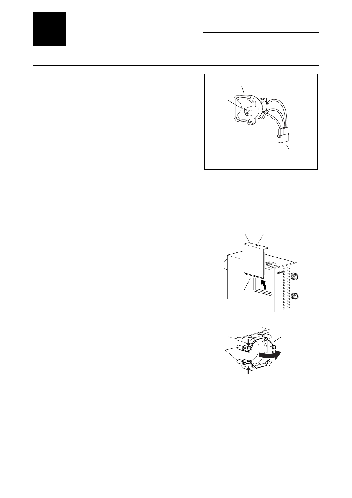
Installing/replacing the mercury lamp
Before installing or replacing a lamp, read all precautions written in
"Safety Precautions" found at the beginning of this instruction manual
and observe them.
Use the Nikon C-LHGFI HG lamp for the mercury lamp.
* Do not touch the inner surface of the reflector and the surface of
the bulb with bare hands.
The mercury lamp is installed to the appropriate position when the
lamp is attached into the lamp holder. There is no need of centering
or focusing the lamp.
• Required tool: M2.5 Hex driver (or hex key)
Turn off the power switch (push down the "0" side). And then, disconnect the power cord from the
1
equipment main body.
Wait for 30 minutes or more to allow the lamp and its
2
surroundings to cool.
Loosen the clamp screw of the lamp replace cover plate,
3
and then remove the lamp replace cover plate.
Lamp with reflector
Bulb
C-LHGFI HG lamp
Lamp replace
Clamp screw
Lamp cable connector
There is a clamping latch on the back of the lamp replace
cover plate. Slide the cover plate up, and then remove it.
Unhook the wire form of the lamp holder.
4
Remove the old lamp when replacing lamps.
(1) Disconnect the lamp cable connector from the
connector on the equipment.
(2) Unhook the wire form and move it to the innermost.
(3) Pull out the old lamp from the lamp holder.
Do not break the used up lamps, but dispose of them as the
special industrial waste or dispose of them according to the
laws or rules of your local waste system.
SHUTTER
INTENSILIGHT
HGFI
-
C
ND
4
8
Latch
Hook
Unhook the wire
form.
2
16
1
32
Wire form
14
Page 17

III Instructions for Use
Attach a new lamp.
5
Set the new lamp with its "TOP" label side up. (See the right
figure.)
(1) Align the lamp with the socket and insert the lamp.
(See the arrow symbol in the right figure.)
Temporarily fix the lamp with the flat springs of the lamp
holder.
(2) While pushing the lamp against the lamp holder,
hook the wire form.
Check that the lamp is fixed firmly.
(3) Connect the lamp cable connector to the connector
on the equipment.
Be careful about the direction of the connector.
Flat springs
Hook
Flat springs
Hook the wire form.
"TOP"
Put the lamp replace cover plate to its original position,
6
and then fix it by tightening the clamping screw.
Slide down the lamp replace cover plate to insert the latch on
the back of the plate into the panel.
Lamp replace
cover plate
Latch
Clamp screw
INTENSILIGHT
HGFI
-
C
Lamp cable
connector
SHUTTER
ND
4
8
2
16
1
32
15
Page 18

III Instructions for Use
Turning on/off the lamp
The mercury lamp turns on/off with the equipment power on/off.
Before turning on the power supply
1
•
Always follow all precautions written in "Safety Precautions" found at the beginning of this instruction
manual.
•
Check that 10 minutes or more elapse after turning off the lamp before turning it on again.
•
Check that the total accumulated lit time of the lamp with RUN TIME hrs. counter. If the indicator of the
counter exceeds the average life expectancy, 2,000 hours or "2000.0" in the indication of the counter, replace
lamp.
Turn on the power by pressing down the power switch to
2
"|" side.
•
The power of the equipment turns on, and the mercury lamp
turns on too.
•
The POWER indicator on the front panel is lit. And the
LAMP indicator flashes. When the mercury lamp is lit
correctly, the LAMP indicator becomes lit.
•
The arc of the lamp will stabilize in about 10 minutes after
being turned on.
RUN TIME hrs.
LAMP
POWER
LAMP indicator
POWER indicator
POWER switch
"|" side: ON
"0" side: OFF
•
For C-HGFIE (motorized type illuminator), indicators on the
HG controller display the equipment status.
(See "HG controller operation for C-HGFIE" on P. 18.)
Open the shutter.
3
Only when the shutter is opened, Illumination is emitted from the equipment.
For details about the shutter operation, see the next page "Opening/closing the shutter."
To turn off the lamp, turn off the power by pressing down the power switch to "0" side.
4
To turn on the lamp again, wait for 10 minutes or more to cool down the lamp.
16
Page 19

III Instructions for Use
Opening/closing the shutter
This equipment has a mechanical shutter. You can control the light transmit/shield by operating the illuminator by the
following operations:
For C-HGFI (manual operation type illuminator)
Rotate the shutter knob on the front side of the equipment to
open/close the shutter.
The shutter closes when "●" is selected. And the shutter opens when
"ο" is selected.
For C-HGFIE (motorized type illuminator)
Push the shutter button on the HG controller to open/close the
shutter.
The shutter open/close state toggles when the shutter button is
pressed. The OPEN indicator turns on when the shutter opens.
Controlling the lamp
You can control the light in six steps by the optical system inside the equipment.
INTENSILIGHT
FI
HG
-
C
R
E
T
T
U
H
S
D
N
4
8
2
6
1
1
2
3
SHUTTER
○: Shutter opens.
●: Shutter closes.
SHUTTER (shutter open/close) knob
LAMP OPEN
SHUTTER
32168421
ND
C-HGFIE
HG CONTROLLER
OPEN indicator
POWER
SHUTTER button
SHUTTER (shutter open/close) button
ND scale 32 16 8 4 2 1
Transmittance
(Brightness)
3%
(1/32)
6.25%
(1/16)
12.5%
(1/8)
For C-HGFI (manual operation type illuminator)
Rotate the ND select knob on the front of the equipment to control the
light.
Be sure to stop the knob at its click stop positions.
For C-HGFIE (motorized type illuminator)
Push the ND select button on the HG controller to control the light.
There are two buttons for controlling the light. The right button is
used to increase the amount of light, and the left button to decrease
the amount of light. The current brightness is displayed on the ND
indicator.
25%
(1/4)
50%
(1/2)
R
E
T
T
U
H
S
T
H
ILIG
S
N
E
T
IN
HGFI
-
C
D
N
4
8
2
6
1
1
2
3
ND select knob
32168421
ND select button
100%
(Not reduced)
ND:Neutral Density
ND
8
16
32
LAMP OPEN
POWER
SHUTTER
ND
C-HGFIE
HG CONTROLLER
ND indicator
ND select button
4
2
1
17
Page 20

III Instructions for Use
Operating the HG controller (only for the C-HGFIE)
For the C-HGFIE, you can control operations of shutter open/close and lamp light control from the HG controller.
Operation parts and indicators of the HG controller are described below.
SHUTTER
ND
C-HGFIE
POWER
Indicator brightness select switch
It changes indicator (LED) brightness in three
steps (bright/dark/off).
SHUTTER button
It toggles the shutter open/close status.
When the shutter opens, the OPEN indicator is
lit.
ND indicator
It displays the current light amount. To control
the light, use the right/left ND select buttons.
ND scale 32 16 8 4 2 1
Transmittance
(brightness)3%(1/32)
6.25%
(1/16)
12.5%
(1/8)
25%
(1/4)
50%
(1/2)
POWER indicator (green)
It is lit when the power turns on.
If the safety interlock activates, this
indicator flashes.
OPEN indicator (green)
It is lit when the shutter opens.
The shutter opens/closes with the shutter
button.
LAMP indicator (yellow)
It is lit when the mercury lamp lights up.
Before the lamp lights up correctly, it
flashes after power on. When the lamp
turns off, this indicator turns off too.
ND select buttons
It switches the light of the equipment in
six steps. The selected amount of light
(brightness) is displayed on the ND
indicator.
The right button is used to increase the
amount of light, and the left button to
decrease the amount of light.
LAMP OPEN
32 16 8 4 2 1
HG CONTROLLER
C-HGFIE-C HG controller
100%
(not
reduced)
Operating the RUN TIME hrs. counter
The RUN TIME hrs. counter on the front panel is an hour meter of the
lamp to check the total accumulated lit time.
The counter is incremented in 0.1 hour step (6 minutes) while the
power is on (the power switch is the "|" side) and displays the total
accumulated lit time of the lamp.
When a new lamp begins its life time, push the reset button of the
counter to set the display as "0.0." When the counter displays "2000.0
(2,000 hours)," the average life expectancy, replace the lamp with new
one.
Do not push the reset button except when the lamp replacing. That will
confuse the replacement period.
RUN TIME hrs.
RUN TIME hrs.
counter
RUN TIME hrs. counter
LAMP
POWER
Reset button
18
Page 21

IV
Even though it is not an equipment failure, this product performance itself can be adversely affected by misuse. If any of
the following symptoms arise, be sure to first check the following table for possible causes before requesting service.
Contact your nearest Nikon representative if the problem cannot be resolved using the following table.
The equipment does not work
even though the power is turned
on (the power switch is "|" side).
The power is on. But the
mercury lamp does not light up
and the LAMP indicator flashes.
The LAMP indicator is lit. But no
illumination light is emitted from
the light guide fiber.
The illumination from the light
guide fiber is dark.
The mercury lamp turns off, the
POWER indicator flashes.
(For the C-HGFIE, an electronic
sound beeps too.)
Indicators on the HG controller
do not light up. (Only for the
C-HGFIE)
The RUN TIME hrs. counter
display disappeared. Or, the
counter does not work correctly.
Troubleshooting
Problem Cause Countermeasure
The power cord is not connected to the
wall outlet, or connected incompletely.
A power rating such as voltage does not
meet the requirements.
The fuse in the equipment is blown. Contact your nearest Nikon
The used lamp is not the specified type. Use the specified lamp (Nikon C-LHGFI
The lamp life is over. Replace the lamp with a new.(P.14)
The lamp cable connector is not
connected correctly.
The source side connector of the light
guide fiber is not connected correctly.
The shutter in the optical path is closed. Operate the shutter open/close knob or
The ND select knob stops at an
intermediate position.
The light guide fiber is not connected
correctly.
The light guide fiber is broken. Replace the light guide fiber with a new
An ND filter with low transmittance is in
the optical path.
The safety protection circuit was
activated.
The indicator brightness select button is
pressed to select "OFF" status.
The internal lithium battery for the RUN
TIME hrs. counter is just about dead.
Connect the power cord securely.
Check the power ratings, voltage and
frequency, of the wall outlet with the
input range of this equipment.
representative.
HG lamp).
Connect the lamp cable connector
properly.(P.14)
Push in the light guide fiber up to the
limited position, and tighten the clamp
screw.
shutter button on the remote controller to
open the shutter.
Rotate the knob to the click stop position.
Connect the light guide fiber correctly.
one.
Adjust the brightness with the ND select
knob (for the manual operation type) or
the ND select button on the HG
controller.
Turn off the power and wait for 10
minutes or more to cool down the lamp.
Take measures to the cause of
protection circuit activation. Then, turn
on the power again.(P.20)
For C-HGFIE (motorized type
illuminator), the ND indicator of the HG
controller displays the cause.(P.20).
Check it before turning off the power.
Press the indicator brightness select
button to change to "bright" or "dark"
status. (The status changes each time
the button is pressed.)
Change the battery. Contact your
nearest Nikon representative.
19
Page 22

IV Troubleshooting
Safety protection circuit
This equipment is provided with a safety protection circuit. The safety protection circuit is activated in the following cases:
• The lamp replace cover plate is opened.
• The temperature around the lamp rises abnormally.
• The number of revolutions of the cooling fan for the lamp mounted in the equipment drops below a predetermined
level.
• The number of revolutions of the cooling fan mounted on the rear panel drops below the predetermined level.
If the safety protection circuit is activates, the following procedures are performed: the mercury lamp turns off, the lamp
indicator turns off, and the power indicator flashes. For C-HGFIE (motorized type illuminator), an electronic sound beeps
and the ND indicator on the HG controller displays the detected problem. (See the followings.)
Indication of detected abnormality (only for C-HGFIE)
In case of C-HGFIE (motorized type illuminator), when the safety protection circuit is activated, one of 1, 2, 4, or 8 ND
indicators on the HG controller lights up to indicate the cause of the problem.
Indicator Cause of problem
1 The lamp replace cover plate is opened.
2 Abnormal temperature around lamp
4 Abnormal rotation of lamp cooling fan
8 Abnormal rotation of rear cooling fan
Resetting the protection circuit
Power off the equipment by turning off the power switch (the "0" side), and remove the problem that caused the
activation of the protection circuit. Then, after waiting for 10 minutes or more until the lamp cools down, power on the
equipment by turning on the power switch (the "|" side).
If the safety protection circuit is activated again after the above procedure, the equipment may be broken. In such cases,
contact your nearest Nikon representative.
20
Page 23

V
Care and Maintenance
Cleaning optical parts
Do not let dust, fingerprint, and such get on the tip of the light guide fiber. Dirt will adversely affect the view of image. If
the tip of the light guide fiber gets dirty, clean it as described below.
• Brush away dust with a soft brush, or else gently wipe it off with gauze.
• Only if there are fingerprints or grease, dampen lightly a piece of soft, clean cotton cloth, lens tissue, or gauze with
absolute alcohol (ethyl or methyl) and gently wipe off the dirt.
• Do not use any organic solvent other than absolute alcohol. The light guide fiber joint surface may be degraded.
• Absolute alcohol is highly flammable. Be careful when handling around open flames and when turning the power
switch on/off, and so on.
• Follow the instructions provided by the manufacturer when using absolute alcohol.
Cleaning painted components
• Do not use organic solvents such as alcohol, ether, or paint thinner. Doing so may result in discoloration of painted
components or plastic components or in peeling of printed letters.
• We recommend that you use a piece of silicon cloth to clean the equipment.
• For persistent dirt, dampen a piece of gauze with neutral detergent and wipe gently.
Cleaning the fan
The filter for the cooling fan on the back of the equipment may be clogged with dust and dirt. (See the figures on P. 10
and 11.) Clean the filter with a vacuum cleaner periodically.
Battery for the RUN TIME hrs. counter
The RUN TIME hrs. counter is equipped with a lithium battery. The life of the battery is approximately 7 years. When the
battery goes dead, the counter display disappears or the counter does not work correctly. In such cases, contact your
nearest Nikon representative.
Storage
• Store this equipment in a dry place where mold is not likely to form.
• Put the dust-proof cover over this equipment to protect it from dust.
• Before putting on the dust-proof cover, turn off the power switch of the equipment (flip it to the "0" position) and wait
until the lamp gets cool sufficiently
• Store the light guide fiber and fiber adapter in a container or desiccator, with a drying agent.
Periodical inspection (charged)
Periodical inspections (expenses charged) of this equipment are recommended in order to maintain peak performance.
Contact your nearest Nikon representative for details.
21
Page 24

V
Controlling by External Equipment (C-HGFIE)
I
C-HGFIE (motorized type illuminator) has a RS-232C interface and a shutter control signal I/O connector. You can
control the illuminator with external equipment such as PCs through these interfaces.
For programming and creating control hardware, follow the descriptions of this chapter.
RS-232C interface
Overview
The C-HGFIE (motorized type illuminator) has a RS-232C interface. You can connect the illuminator with a PC or other
equipment. Read the followings to use the RS-232C interface.
Communication parameters
Baud rate 9600 bps (fixed)
Data length 8 bits (fixed)
Parity bit None
Stop bit 1 bit (fixed)
Flow control None
Connector pin assignments and cable specifications
Use a crossed type cable with D-sub 9 pin connectors.
(Reference) Crossed type cable on the market
22
Page 25

VI Controlling by External Equipment (C-HGFIE)
Command format
The data format used when this illuminator receives data from external equipment is referred to as "command format,"
while that used when the system sends data is called "response format." In the following description, [ ] indicates a
delimiter for explanation purpose and not data (characters) that is actually sent or received.
Command format
[ A ] [ B B B ] [ C . . . C ] [ C R ]
[ A ] Command identifier (following three types)
Identifier Description
f Command with response when received
c Command without response when received
r Data request command
[BBB] Command name
[C...C] Parameter (if required)
Response Format
[ D ] [ B B B ] [ E . . . E ] [ C R ] [ L F ]
[ D ] Response identifier (following four types)
Identifier Description
q Response to f command
o Response when [f] or [c] command processing is normally terminated
n Response if an error occurs during [f], [c], or [r] command processing
a Response to [r] command (requested data)
[BBB] Command name
[E...E] Data ("A", error code, or requested data)
Error Code
Code Type Description
1 Command error Command identifier or command name is bad.
2 Parameter error Parameter is bad.
3 Process timeout Timeout error occurred in the motorized mechanism control.
4 Receive buffer overflow Received data exceeds the limit.
6 Command overflow Number of commands exceeds the limit for the drive table.
7 Processing inhibit error Processing is disabled in the software. Limit error or such.
8 Initialization error This illuminator has not initialized.
* Code number 5 does not occur on this illuminator.
23
Page 26

Communication sequence
[f] command
[c] command
VI Controlling by External Equipment (C-HGFIE)
[C-HGFIE] [External equipment such as PC]
[f] command
[q] response
Command processing
[o] response
* If an error occurs in the command processing, [n] response is issued.
[C-HGFIE] [External equipment such as PC]
[r] command
Communication buffer
[c] command
Command processing
[o] response
* If an error occurs in the command processing, [n] response is issued.
[C-HGFIE] [External equipment such as PC]
[r] command
Command processing
[a] response
* If an error occurs in the command processing, [n] response is issued.
Communication commands can be sent up to 100 commands (or 2048 characters) in a row without waiting for
responses.
However, the process sequence may be differ from the sent command order when multiple commands are sent.
Normally, the sent order will be kept when drive commands for the same equipment are sent in a row.
24
Page 27

Communication command
ND control
1. Command list
Description of operation Command Response
ND forward rotation
Rotate the ND to the next stop in the forward direction.
(address increment)
ND reverse rotation
Rotate the ND to the next stop in the reverse direction.
(address decrement)
ND position specification
Move the ND to the specified position.
ND position read
Read the ND position.
2. Parameter
VI Controlling by External Equipment (C-HGFIE)
fNCW
cNCW
fNCC
cNCC
fNDM(1)
cNDM(1)
rNAR aNAR(1)
qNCWA
oNCW
nNCW(2) (error response)
qNCCA
oNCC
nNDD(2) (error response)
qNDMA
oNDM
nNDM(2) (error response)
nNAR(2) (error response)
(1) Position (address): 1 = ND1, 2 = ND2, 3 = ND4, 4 = ND8, 5 = ND16, and 6 = ND32
(2) Error code (See P.23.)
Shutter control
1. Command list
Shutter control
Control the shutter to the specified status.
hutter status read
Read the shutter status.
Shutter control by schedule
Control the shutter to the specified status and reverse its
status at the specified time.
2. Parameter
(1) Status: 0 = reverse, 1 = open, or 2 = close
(2) Open time (4 bytes fixed): 0000 to 1000
(3) Error code (See P.23.)
Description of operation Command Response
fSXC(1)
cSXC(1)
rSXR aSXR(1)
fSXT(1):(2)
cSXT(1):(2)
* See the note on the next page.
* 0001 denotes 0.1 second. Up to 100.0 seconds can be set in 0.1 second step.
However, 0000 denotes continuous open status.
qSXCA
oSXC
nSXC(3) (error response)
nSXR(3) (error response)
qSXTA
oSXT
nSXT(3) (error response)
25
Page 28

VI Controlling by External Equipment (C-HGFIE)
[
]
3. Note for the shutter control by schedule (SXT command)
<Protocol>
C-HGFIE
cSXT1:0010
[PC or so on]
Shutter opens.
oSXT
1 sec.
Shutter closes.
(No response)
<NOTE>
The following limitations must be noted about this command.
When a shutter control by schedule command is sent to this illuminator and the shutter open/close schedule is
set, the following cases occur.
(A) If a communication command other than shutter control commands is issued, that communication
command is processed.
(B) If a shutter control command is issued, the shutter control command is processed.
The new shutter control command is processed, and the shutter control by schedule command is
disabled.
(C) If another shutter control by schedule command is issued, the new command is processed.
The new schedule is enabled.
The items of (A) and (B) are applied for shutter controls by the remote controller or external signals.
<Example>
[C-HGFIE]
[External equipment such as PC]
Shutter opens.
(1.5 sec.)
Shutter opens.
(1.0 sec.)
Shutter closes.
cSXT1:0020
oSXT
cSXT2:0040
oSXT
cSXC1 (shutter close)
oSXC
(1) Setting to close the
shutter after 2.0 sec.
Before 2.0 sec. time-lapse
(2) Setting to close the
shutter after 4.0 sec.
Before 4.0 sec. time-lapse
(3) Shutter close command
(4) Close the shutter and
return a response.
Specified schedule is
disabled.
26
Page 29

Remote controller
1. Command list
Remote controller enable set
Set the remote controller enabled.
Remote controller enable read
Read the remote controller validity.
Remote controller LED brightness change
Change the remote controller LED brightness.
Remote controller LED brightness read
Read the remote controller LED brightness.
2. Parameter
(1) Validity: 0 = disabled (initial condition), 1 = enabled
(2) LED brightness: 0 = off, 1 = dark, 2 = bright, 9 = toggle (off → dark →bright → off
(3) Error code (See P.23.)
VI Controlling by External Equipment (C-HGFIE)
Description of operation Command Response
cREM(1) oREM
nREM(3) (error response)
rREN aREN(1)
nREN(3) (error response)
cRIL(2) oRIL
nRIL (3) (error response)
rRIR aRIR(2)
nRIR(3) (error response)
* When the validity is disabled, the button operation on the remote controller is
disabled. (No reaction even if a button is pressed.)
→...)
Program version read
1. Command list
Description of operation Command Response
Version read *
Read the program version number.
2. Parameter
(1) Program version (5 bytes fixed): "V*.**"
(2) Error code (See P.23.)
Program checksum read
1. Command list
Description of operation Command Response
Checksum read *
Read the checksum of the program.
2. Parameter
(1) Program checksum (4 bytes fixed): "0000" to "FFFF" (hex)
(2) Error code (See P.23.)
rVEN aVEN(1)
nVEN(2) (error response)
rSUM aSUM(1)
nSUM(2) (error response)
27
Page 30

VI Controlling by External Equipment (C-HGFIE)
Shutter control by external signal
C-HGFIE (motorized type illuminator) has a connector to control opening/closing of the shutter by external equipment.
You can use an external switch box, PC and so on, to control the shutter and to read the shutter status.
To use the shutter control signal I/O connector, connect signals according to the description below.
Connector pin configuration
For the equipment side connector, a 3.5 mm diameter audio mini-stereo jack is adopted. Follow the instruction
below to make the connection.
1: GND Ground
2: EX-SHT-IN Shutter control signal input
3: EX-SHT-OUT Shutter control signal output
Connector circuit
diagram
Usage
1. Opening/closing of the shutter
Making a short circuit between the pin No. 2 (EXT-SHT-IN) and
No.1 (GND) performs switching of the shutter opening/closing.
By connecting a momentary type switch, the shutter status can
be switched every time the switch is pressed.
Or, the shutter opening/closing is also possible by TTL level
logical input. In this case, the shutter status is switched at every
fall edge (from high to low) of a signal.
Signal
input
Control
signal
The input signal terminal is configured to
feed the signal to the Schmidt trigger inverter
through a 10 kΩ resistor.
2. Shutter status read-out
The pin No.3 (EXT-SHT-OUT) outputs the open collector output
of the transistor. The transistor is ON when the shutter is open,
and OFF when it is closed.
Input terminal condition:
High level threshold value: 2.31 V (min.)
Low level threshold value: 0.3 V (max.)
Signal
output
Control
signal
Pull-up condition
I: 30 mA (max.)
Pull-up voltage: +12 V (max.)
28
Page 31

V
II
Model C-HGFI Intensilight (Precentered Fiber Illuminator) (manual operation type)
Shutter Shutter system: light shield plate insertion/removal type
Light control function Light control system: punching metal rotation
Available mercury lamp Model name: Nikon C-LHGFI HG lamp
Specifications
C-HGFIE Intensilight (Precentered Fiber Illuminator) (motorized type)
Drive system: manual operation type (C-HGFI) or motorized type (C-HGFIE)
Light control range: ND1, ND2, ND3, ND4, ND8, ND16, and ND32 (6 steps)
Wavelength range: 380 to 600 nm
Drive system: manual operation type (C-HGFI) or motorized type (C-HGFIE)
Ratings: 130 W DC
Lighting system: DC lighting
Average service life*:2,000 hrs.
* The average service life is defined as the hours at which 50% or more
normally working lamps still light up with the brightness of 50% or more of
the initial optical characteristics after the usage of lifetime lighting (lighting
cycle: repetition of 3.5 hours on, and then 0.5 hour off).
Available light guide fiber Model name: Nikon HG fiber 15 C-HGFIF15 (cable length 1.5 m)
Nikon HG fiber 30 C-HGFIF30 (cable length 3.0 m)
Core diameter: 3 mm
Input ratings 100 to 240 VAC (±10%), 50/60 Hz, 2.0 A
Power cord For Japan:
Detachable cord set with a PSE mark, 3 conductor type
(3 conductor grounding Type HVCTF, 1.25 mm
maximum, rated at 125 VAC minimum.)
For countries excluding Japan where the power supply is 100 to 120 VAC:
UL Listed detachable cord set, 3 conductor grounding Type
SVT, No.18 AWG, 3 m long maximum, rated at 125 VAC
minimum.
For countries where the power supply is 220 to 240 VAC:
Approved according to EU/EN standards, 3 conductor
grounding Type HO5VV-F, 3 m long maximum, rated at 250
VAC minimum.
Dimensions and weight Dimensions: 110 (W) x 283 (H) x 258 (D) mm
(C-HGFI/C-HGFIE main body excluding protruding portion)
Weight: approximately 6.0 kg (C-HGFI)
approximately 6.0 kg (C-HGFIE)
2
, 3 m long
Remote controller
(only for C-HGFIE)
Model name: C-HGFIE-C HG controller
Connector: mini DIN 8 pin
Cable length: 2.8 m
Dimensions: 67 (W) x 122 (H) x 20 (D) mm (excluding protruding portion)
Weight: Approximately 0.2 kg
29
Page 32

Communication function
(only for C-HGFIE)
VII Specifications
Communication type:RS-232C compliance serial interface
Connector: D-sub 9 pin
Shutter control signal
Connector: 3.5 mm diameter type stereo mini jack
(only for C-HGFIE)
Operating environment Temperature: 0 to +35°C
Relative humidity: 85% relative humidity maximum (no condensation)
Altitude: 2000 m maximum
Pollution degree: Degree 2
Installation category: Category II
Electric shock protection class: Class I, indoor use only
Storage environment Temperature: -20 to +60°C
Relative humidity: 90% relative humidity maximum (no condensation)
Safety standard
compliance
• CE marking
• This product meets EU Low Voltage Directive requirements.
• This product has obtained GS mark. (EN61010-1:2001)
• This product meets EU EMC Directive requirements. (EN61326)
• This is the UL-listed product.(UL61010-1 (Second Edition))
• This product meets FCC Part 15B Class A requirements.
This equipment has been tested and found to comply with the limits for a Class A digital
device, pursuant to Part 15 of the FCC Rules.
These limits are designed to provide reasonable protection against harmful interference when
the equipment is operated in a commercial environment.
This equipment generates, uses, and can radiate radio frequency energy and, if not installed
and used in accordance with the instruction manual, may cause harmful interference to radio
communications.
Operation of this equipment in a residential area is likely to cause harmful interference in
which case the user will be required to correct the interference at his own expense.
• This Class A digital apparatus complies with Canadian ICES-003.
Cet appreil numérique de classe A est conforme à la norme NMB-003 du Canada.
• This product complies with Australian EMC. (AS/NZS C1SPR11 Group1 Class B)
Acoustic Noise Less than 70 dB
Maschinenlärminformations-Verordnung - 3. GPSGV, 06.01.2004:
Der höchste Schalldruckpegel beträgt 70 dB(A) oder weniger gemäß EN ISO 7779
30
Page 33

V
III
Connection to a Microscope
Microscope
main body
TE2000-E
TE2000-U
TE2000-S
90i
80i
55i
50i
TS-100 T1-FM HG Adapter T1-HGFIA
LV100DA
LV150
LV150A
Epi illumination
attachment
T-FL
T-FL- E
D-FL
U-EPI-FL
D-DH-E DIH E
D-DH-E DIH M
J-FL
LV-UEPI2
LV-UEPI2A
Adapter HG fiber Fiber illuminator
FL Adapter T-FLA
FL Zoom Adapter
T-FLZA
HG Adapter C-HGFIB
HG Fiber Adapter LV-HGFA LV100D
Double Light Source Adapter
LVUEPI2-DLS
HG Adapter
C-HGFIA
HG Fiber (1.5 m)
C-HGFIF 15
HG Fiber (3 m)
C-HGFIF 30
Precentered Fiber Illuminator
(manual operation type)
Intensilight C-HGFI
Precentered Fiber Illuminator
(motorized type)
Intensilight C-HGFIE
31
 Loading...