


 Loading...
SERVICE MANUAL
ECG9010K
ECG9020K
cardiofax GEM
ELECTROCARDIOGRAPH
ECG-9010K
ECG-9020K
0634-001307A
|
|
CONTENTS |
|
Contents |
|
|
Conventions Used in this Manual and Instrument .................................................................... |
i |
|
Warnings, Cautions and Notes ...................................................................................... |
i |
|
Explanations of the Symbols in this Manual and Instrument ......................................... |
i |
Section 1 |
General ................................................................................... |
1C.1 |
|
Introduction ......................................................................................................................... |
1.1 |
|
Service Policy ..................................................................................................................... |
1.2 |
|
Specifications ...................................................................................................................... |
1.3 |
|
Panel Description ................................................................................................................ |
1.5 |
|
ECG-9010K Electrocardiograph ............................................................................... |
1.5 |
|
Top View ......................................................................................................... |
1.5 |
|
Operation Panel .............................................................................................. |
1.6 |
|
Right Side Panel ............................................................................................. |
1.7 |
|
ECG-9020K Electrocardiograph ............................................................................... |
1.8 |
|
Top View ......................................................................................................... |
1.8 |
|
Operation Panel .............................................................................................. |
1.9 |
|
Right Side Panel ........................................................................................... |
1.10 |
|
Composition ...................................................................................................................... |
1.11 |
|
ECG-9010K Electrocardiograph ............................................................................. |
1.11 |
|
ECG-9020K Electrocardiograph ............................................................................. |
1.12 |
|
Location ............................................................................................................................ |
1.13 |
|
Block Diagram ................................................................................................................... |
1.14 |
|
Connection Diagram ......................................................................................................... |
1.15 |
Section 2 |
Maintenance ........................................................................... |
2C.1 |
|
Replacement ....................................................................................................................... |
2.1 |
|
Periodic Replacement Schedule ............................................................................... |
2.1 |
|
Cleaning .............................................................................................................................. |
2.2 |
|
Cleaning and Greasing Schedules ........................................................................... |
2.2 |
|
Cleaning the Paper Mark Sensor and Paper Empty Sensor ..................................... |
2.2 |
|
Cleaning the Motor Rotation Sensor and |
|
|
Greasing the Motor Gear and Gear Meshed with Motor Gear .................................. |
2.3 |
Section 3 |
Troubleshooting and System Error Message ...................... |
3C.1 |
|
Troubleshooting Flowchart .................................................................................................. |
3.1 |
|
Troubleshooting Table.......................................................................................................... |
3.4 |
|
Troubleshooting General Operation Problem ............................................................ |
3.4 |
|
Troubleshooting Recording Problem ......................................................................... |
3.6 |
|
System Error Message ....................................................................................................... |
3.7 |
Service Manual ECG-9010/9020 Rev A |
C.1 |
CONTENTS
Section 4 |
System Test, Adjustment and Setting .................................. |
4C.1 |
|
System Test ........................................................................................................................ |
4.1 |
|
Overall ...................................................................................................................... |
4.1 |
|
Calling up the Test Level 1 ........................................................................................ |
4.2 |
|
Calling up the Test Level 2 ........................................................................................ |
4.3 |
|
Entering the System Test Number ............................................................................ |
4.4 |
|
Executing the System Test ........................................................................................ |
4.5 |
|
Quitting the System Test ........................................................................................... |
4.6 |
|
Exiting the System Test Mode ................................................................................... |
4.6 |
|
Demonstration .................................................................................................................... |
4.7 |
|
Recorder ............................................................................................................................. |
4.8 |
|
Thermal Head ................................................................................................................... |
4.11 |
|
Key .................................................................................................................................... |
4.12 |
|
Memory ............................................................................................................................. |
4.13 |
|
Single Memory Test Mode ...................................................................................... |
4.14 |
|
Continuous Memory Test Mode .............................................................................. |
4.14 |
|
LCD/LED ........................................................................................................................... |
4.15 |
|
Input Unit .......................................................................................................................... |
4.17 |
|
Calibration ......................................................................................................................... |
4.18 |
|
Communication ................................................................................................................. |
4.19 |
|
CRO/EXT1 ........................................................................................................................ |
4.21 |
|
System Setup Initialization ................................................................................................ |
4.23 |
|
ECG Findings List Recording ............................................................................................ |
4.24 |
|
Recording Resolution Setting ........................................................................................... |
4.25 |
|
Cue Mark Adjustment ....................................................................................................... |
4.26 |
|
Date and Time Setting ...................................................................................................... |
4.28 |
|
Setting the Date and Time ............................................................................ |
4.28 |
Section 5 |
Board/Unit Description .......................................................... |
5C.1 |
|
Block Diagram ..................................................................................................................... |
5.1 |
|
Power Unit........................................................................................................................... |
5.2 |
|
ECG Control Board ............................................................................................................. |
5.2 |
|
Flash ROM Board ............................................................................................................... |
5.3 |
|
Inverter Board ..................................................................................................................... |
5.3 |
Section 6 |
Disassembly and Assembly .................................................. |
6C.1 |
|
Before You Begin ................................................................................................................. |
6.1 |
|
Warnings and Cautions ............................................................................................ |
6.1 |
|
Required Tools .......................................................................................................... |
6.1 |
|
Board and Unit Location ........................................................................................... |
6.2 |
|
Cable Connection ..................................................................................................... |
6.3 |
|
Removing the Top Casing ................................................................................................... |
6.4 |
|
Removing the LCD Assy ..................................................................................................... |
6.5 |
|
Removing the Thermal Head Assy ..................................................................................... |
6.6 |
|
Removing the Motor Assy ................................................................................................... |
6.8 |
|
Removing the Speaker Assy ............................................................................................... |
6.9 |
C.2 |
Service Manual ECG-9010/9020 Rev A |
|
CONTENTS |
Removing the Inverter Board ............................................................................................ |
6.10 |
Removing the ECG Control Board .................................................................................... |
6.11 |
Removing the Power Unit.................................................................................................. |
6.12 |
Replacing the Thermistor and Termistor Cable ....................................................... |
6.14 |
Removing the Battery Terminal Assy ................................................................................ |
6.15 |
Removing the Magazine Assy .......................................................................................... |
6.16 |
Removing the Bottom Casing ........................................................................................... |
6.17 |
Replacing the Fuse on the Power Board ........................................................................... |
6.18 |
Replacing the Lithium Battery on the ECG Control Board ................................................ |
6.19 |
Section 7 |
Replaceable Parts List ........................................................... |
7C.1 |
|
General Parts List ............................................................................................................... |
7.2 |
|
Top Casing Assy ................................................................................................................. |
7.4 |
|
Top Casing Assy, RK-0007 for ECG-9010K .............................................................. |
7.4 |
|
Top Casing Assy, RK-0009 for ECG-9020K .............................................................. |
7.5 |
|
Thermal Head Assy, YZ-011H8 ........................................................................................... |
7.6 |
|
Motor Assy, GC-0011 .......................................................................................................... |
7.7 |
|
Speaker Assy, RK-0005 ...................................................................................................... |
7.8 |
|
Magazine Assy, RH-0001 ................................................................................................... |
7.9 |
|
Battery Terminal Assy, RK-0006 ....................................................................................... |
7.10 |
|
LCD Assy, VL-0001 ........................................................................................................... |
7.11 |
|
Cart and Fixing Plate ........................................................................................................ |
7.12 |
|
Patient Cable Hanger ........................................................................................................ |
7.14 |
Section 8 |
Connector Pin Assignment ................................................... |
8C.1 |
|
Power Unit........................................................................................................................... |
8.1 |
|
CN11 (to AC Inlet) .................................................................................................... |
8.1 |
|
CN21 (to ECG control board) ................................................................................... |
8.1 |
|
CN31 (to Thermal Head) .......................................................................................... |
8.1 |
|
CN51 (to Battery)...................................................................................................... |
8.1 |
|
ECG Control Board ............................................................................................................. |
8.2 |
|
CNJ011 (to Thermal Head) ....................................................................................... |
8.2 |
|
CNJ012 (to Inverter Board) ....................................................................................... |
8.2 |
|
CNJ013 (to LCD) ...................................................................................................... |
8.3 |
|
CNJ021 (to Flash ROM Board) ................................................................................. |
8.3 |
|
CNJ031 (to SIO Connector)...................................................................................... |
8.5 |
|
CNJ032 (to Key Connector) ...................................................................................... |
8.5 |
|
CNJ033 (to Speaker) ................................................................................................ |
8.6 |
|
CNJ035 (to Power Unit) ............................................................................................ |
8.7 |
|
CNJ036 (to Motor) .................................................................................................... |
8.8 |
|
CNJ041 (to CRO Connector) .................................................................................... |
8.8 |
|
CNJ043 (to EXT INPUT Connector) ......................................................................... |
8.8 |
|
CNJ091 (to ECG Connector) .................................................................................... |
8.9 |
|
Flash ROM Board ............................................................................................................. |
8.10 |
|
CNJ021 (to ECG Control Board) ............................................................................ |
8.10 |
Service Manual ECG-9010/9020 Rev A |
C.3 |
CONTENTS
Inverter Board ................................................................................................................... |
8.12 |
CN1 (to ECG Control Borad) .................................................................................. |
8.12 |
CN2 (to LCD module) ............................................................................................. |
8.12 |
External Input/Output Socket ............................................................................................ |
8.13 |
SIO Socket .............................................................................................................. |
8.13 |
EXT Input and CRO Output .................................................................................... |
8.13 |
C.4 |
Service Manual ECG-9010/9020 Rev A |
Conventions Used in this Manual and Instrument
Warnings, Cautions and Notes
Warnings, cautions and notes are used in this manual to alert or signal the reader to specific information.
WARNING
A warning alerts the user to the possible injury or death associated with the use or misuse of the instrument.
CAUTION
A caution alerts the user to possible injury or problems with the instrument associated with its use or misuse such as instrument malfunction, instrument failure, damage to the instrument, or damage to other property.
NOTE
A note provides specific information, in the form of recommendations, prerequirements, alternative methods or supplemental information.
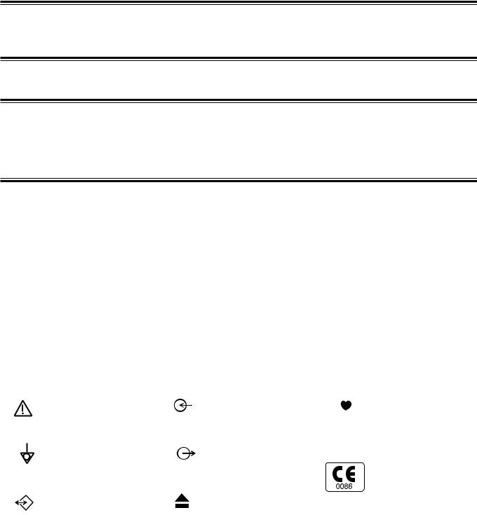
Explanations of the Symbols in this Manual and Instrument
The following symbols found in this manual/instrument bear the respective descriptions as given.
Cardiograph
Attention, consult |
Input terminal for analog |
|
|
Type CF applied part |
|
||||
operator’s manual |
signal |
|
|
|
|
|
|
||
|
|
|
|
|
Equipotential terminal |
Output terminal for analog |
|
|
The CE mark is a protected |
signal |
|
|
conformity mark of |
|
|
|
|
|
European Community. |
|
|
|
|
The products herewith |
|
|
|
|
|
|
|
|
|
comply with the |
Serial input/output terminal |
Eject (magazine release |
|
|
requirements of the |
button) |
|
|
Medical Device Directive |
|
|
|
|
|
93/42/EEC. |
|
|
|
|
|
Service Manual ECG-9010/9020 Rev A |
i |
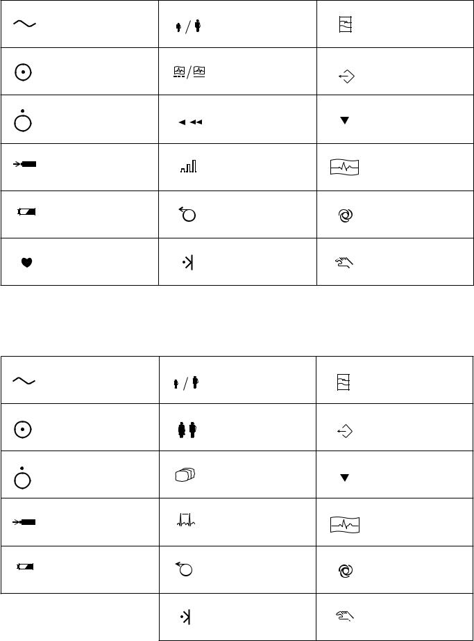
Operation panel (for ECG-9010K onlly)
Alternating current |
Age |
Filter |
|
“On” only for a part of |
REST/PERIODIC |
Copy |
|
equipment |
recording |
||
“Off” only for a part of |
Paper speed |
Calibration |
|
equipment |
|||
|
|
||
Battery charging (lamp/on |
Gain |
START/STOP recording |
|
screen) |
|||
|
|
||
Battery check (lamp/on |
Paper feed |
Automatic control |
|
screen) |
|||
|
|
||
QRS sync lamp |
Mark |
Manual control |
Operation panel (for ECG-9020K only)
Alternating current |
Age |
Filter |
|
|
|
||
“On” only for a part of |
Sex |
Copy |
|
equipment |
|||
|
|||
“Off” only for a part of |
Mode |
Calibration |
|
equipment |
|
||
|
|
||
Battery charging (lamp/on |
Rhythm |
START/STOP recording |
|
screen) |
|
||
|
|
||
Battery check (lamp/on |
Paper feed |
Automatic control |
|
screen) |
|||
|
|||
|
Mark |
Manual control |
ii |
Service Manual ECG-9010/9020 Rev A |

Display (for ECG-9020K only)
QRS sync lamp
Patient cable
Attention, consult |
|
|
|
|
|
Defibrillation-proof |
|
|
|
|
|||
operator’s manual |
|
|
|
|
|
Type CF applied part |
|
|
|
||||
|
|
|
|
|
|
|
Service Manual ECG-9010/9020 Rev A |
iii |
Section 1 General
Introduction ........................................................................................................................ |
1.1 |
Service Policy .................................................................................................................... |
1.2 |
Specifications ..................................................................................................................... |
1.3 |
Panel Description ............................................................................................................... |
1.5 |
ECG-9010K Electrocardiograph .............................................................................. |
1.5 |
Top View ........................................................................................................ |
1.5 |
Operation Panel ............................................................................................. |
1.6 |
Right Side Panel ............................................................................................ |
1.7 |
ECG-9020K Electrocardiograph .............................................................................. |
1.8 |
Top View ........................................................................................................ |
1.8 |
Operation Panel ............................................................................................. |
1.9 |
Right Side Panel .......................................................................................... |
1.10 |
Composition ..................................................................................................................... |
1.11 |
ECG-9010K Electrocardiograph ............................................................................ |
1.11 |
ECG-9020K Electrocardiograph ............................................................................ |
1.12 |
Location ........................................................................................................................... |
1.13 |
Block Diagram .................................................................................................................. |
1.14 |
Connection Diagram ........................................................................................................ |
1.15 |
Service Manual ECG-9010/9020 Rev A |
1C.1 |

1. GENERAL
Introduction
This service manual provides useful information to qualified service personnel to understand, troubleshoot, service, maintain and repair the ECG-9010K/9020K Electrocardiograph (referred to as “the instrument” in this service manual).
All replaceable parts or units of this instrument and its optional units are clearly listed with exploded illustration to help you locate the parts quickly.
The System test, Adjustment and Setting section in this service manual describes the maintenance that should be performed by qualified service personnel. The Maintenance section in the operator’s manual describes the maintenance that can be performed by the user.
The information in the operator’s manual is primarily for the user. However, it is important for service personnel to thoroughly read the operator’s manual and service manual before starting to troubleshoot, service, maintain or repair this instrument. This is because service personnel needs to understand the operation of the instrument in order to effectively use the information in the service manual.
Service Manual ECG-9010/9020 Rev A |
1.1 |
1. GENERAL
Service Policy
Nihon Kohden Corporation’s basic policy for technical service is to replace faulty units, printed circuit boards or parts. We do not support component-level repair of boards and units outside the factory for the following reasons:
•A special facility is necessary to repair multi-layer boards because most of the components on the board are SMD (surface mount devices) and most of the circuits employ a gate array method.
•To fulfill safety certification requirements, a special facility is necessary to verify safety as medical equipment after the power unit is repaired.
NOTE
•When ordering parts or accessories from your nearest Nihon Kohden Corporation’s distributor, please quote the NK code number and part name which is listed in this service manual, and the name or model of the unit in which the required part is located. This will help us to promptly attend to your needs.
•Always use parts and accessories recommended or supplied by Nihon Kohden Corporation to assure maximum performance from your instrument.
1.2 |
Service Manual ECG-9010/9020 Rev A |

1. GENERAL
Specifications
ECG input |
|
Input impedance |
10 MΩ or more |
Electrode offset tolerance |
±500 mV or more |
Input unit protection |
Isolated and defibrillator protected |
Standard sensitivity |
10 mm /mV ±2% |
Common mode rejection ratio |
100 dB or more |
Frequency response |
0.05 to 150 Hz (– 3 dB or more) |
Waveform data processor |
|
Sample rate |
500 samples/s (input unit: 8,000 samples/s) |
AC line filter |
50/60 Hz, OFF |
High-cut filter |
75, 100, 150 Hz |
EMG filter |
25/35 Hz |
Time constant |
3.2 s or more |
Waveform status detection |
Electrode detachment (polarization voltage), |
|
Noise (high frequency) |
Sensitivity selection |
5, 10 , 20 mm/mV |
LCD (monochrome with CCFT backlight) (for ECG-9020K only)
Size |
5.6 inch |
|
|
Number of dots |
320 × 240 |
|
|
ECG waveform |
3 channel:Real time 12 ECG lead complexes |
||
|
6 channel: 2.5 s |
|
|
|
Rhythm lead: 10 s |
|
|
Displayed data |
Waveform, patient information, recording settings, |
||
|
operation mode, heart rate, QRS sync mark, error message, |
||
|
electrode detachment, noise |
|
|
Recorder |
|
|
|
Printing method |
High resolution thermal printer head |
|
|
Printing density |
200 dpi (8 dots/mm) |
|
|
Scanning line density |
1 ms |
|
|
Recording width |
104 mm |
|
|
Number of recording channels |
2, 3, 4, 6 |
|
|
Paper speed |
10, 12.5, 25, 50 mm/s |
|
|
|
(10 and 12.5 mm/s available for ECG-9020K only) |
||
Printed data |
Program type, version, date and time, paper speed, sensitivity, |
||
|
lead name, filter, hospital name, patient information, |
||
|
timing mark, event mark, electrode detachment, noise |
||
Mechanical noise |
48 dB or less at paper speed 25 mm/s |
|
|
External input/output |
|
|
|
External input |
10 mm/0.5 V ±5%, input impedance 100 k Ω |
or more |
|
Signal output |
0.5 V/1 mV ±5%, output impedance 100 Ω |
or less |
|
Serial I/O |
Communication method: |
RS-232C |
|
Baud rate: |
2400, 4800, 9600, 19200, 38400, |
|
57600, 115200 |
Service Manual ECG-9010/9020 Rev A |
1.3 |
1. GENERAL
Power requirement |
|
|
|
|
Line voltage |
100 to 127 VAC, 220 to 240 VAC ±10% |
|
||
Line frequency |
50 or 60 Hz |
|
||
Power input |
Up to 120 VA |
|
||
Power consumption |
49 W or less |
|
||
Built-in battery) |
Voltage: |
12 V |
|
|
(LCT-1912ANK) |
Current consumption: 6A or less |
|
||
Environment |
|
|
|
|
Operating temperature |
|
10 to 40°C |
|
|
Operating humidity |
|
25 to 90% RH |
|
|
Operating atmospheric pressure |
|
70 to 106 kPa |
|
|
Storage duration and temperature |
|
2 weeks or less: |
− 20 to 65°C |
|
(Depends on the battery) |
|
Between 2 weeks and One year: |
− 15 to 40°C |
|
|
|
Over one year: |
− 15 to 25°C |
|
Storage humidity |
|
10 to 95% RH (non condensing) |
|
|
Storage atmospheric pressure |
|
70 to 106 kPa |
|
|
Recording paper storage temperature |
− |
20 to 50°C |
|
|
Recording paper storage humidity |
|
25 to 90% RH |
|
|
Electromagnetic compatibility |
|
Class B |
|
|
Other |
|
Indoor portable |
|
|
Dimensions and weight
Dimensions |
280 W × 52 H × 216 D mm (excluding protrusions) |
Weight |
ECG-9010K: approx. 2.5 kg (with battery), approx. 1.9 kg (without battery) |
|
ECG-9020K: approx. 2.9 kg (with battery), approx. 2.1 kg (without battery) |
Safety
Safety standard:
IEC601-1 Amendment 1,2
IEC601-2-25
Type of protection against electric shock:
AC power: Class I
Batty power: Internally powered equipment
Degree of protection against electric shock:
Defibrillator proof type CF applied part when patient cable BJ-901D, BJ-902D or BJ-903D is used
Degree of protection against harmful ingress of water:
Ordinary equipment
Degree of safety of application in the presence of a flammable anaesthetic mixture with air, oxygen or nitrous oxide:
Not suitable for use in the presence of a flammable anaesthetic mixture with air, oxygen or nitrous oxide
Mode of operation:
Continuous
1.4 |
Service Manual ECG-9010/9020 Rev A |
1. GENERAL
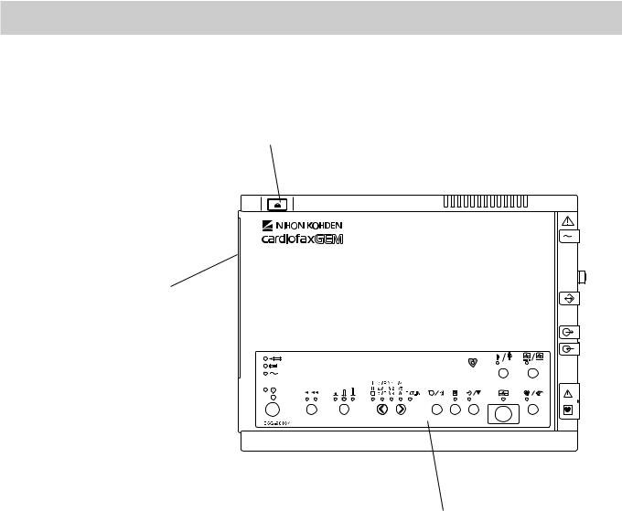
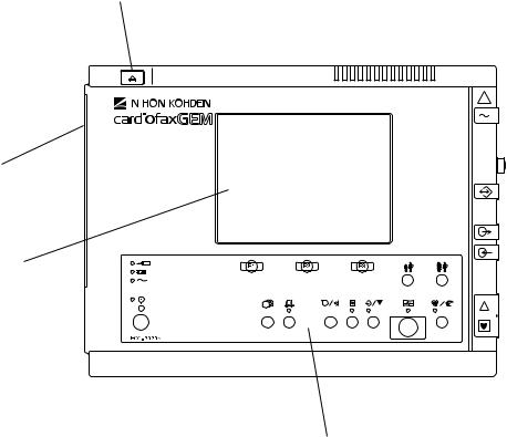
Panel Description
ECG-9010K
Electrocardiograph
Top View
3
2
1
Name
1.Operation panel
2.Magazine (recording paper container)
3.Magazine release button
Service Manual ECG-9010/9020 Rev A |
1.5 |
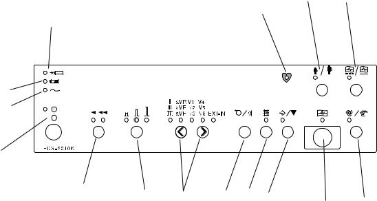
1. GENERAL
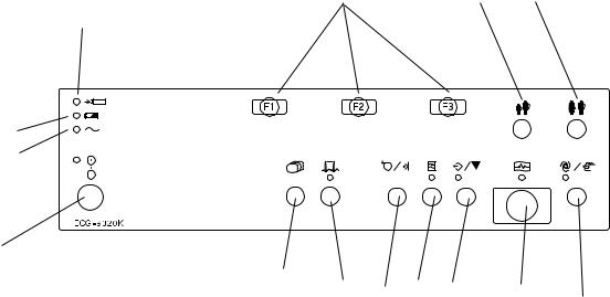
Operation Panel
14 13
18
4
5
6
7
15 |
16 |
17 |
8 |
9 |
10 |
|
|
12 |
|||||
|
|
|
|
|
11 |
Name
4.Battery charge lamp
5.Battery operation lamp
6.AC power lamp
7.POWER key/lamp
8.FEED/MARK key
9.FILTER key/lamp
10.COPY/CAL key/lamp
11.START/STOP key/lamp
12.AUTO/MANUAL key/lamp
13.REST/PERIODIC key/lamp
14.AGE key/lamp
15.SPEED key/lamp
16.GAIN key/lamp
17.LEAD keys/lamp
18.QRS sync lamp
1.6 |
Service Manual ECG-9010/9020 Rev A |

1. GENERAL
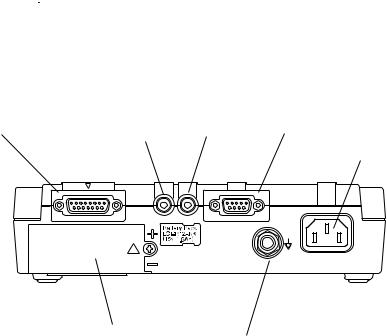
Right Side Panel
For the  mark, refer to the descriptions for the Right Side Panel in Section 1 “Panel Descriptions” of the ECG-9010K Operator’s Manual.
19 |
20 |
21 |
22 |
|
|
23
24
25
Name
19.Patient input connector
20.EXT-IN connector
21.CRO-OUT
22.SIO connector
23.AC power cord socket
24.Battery compartment
25.Equipotential ground terminal
Service Manual ECG-9010/9020 Rev A |
1.7 |
1. GENERAL
ECG-9020K |
Top View |
|
Electrocardiograph |
|
|
|
3 |
|
|
|
|
|
|
|
|
|
|
|
|
|
|
|
|
|
|
|
2
4
1
Name
1. Operation panel
2. Magazine (recording paper container)
3. Magazine release button
4. LCD screen
1.8 |
Service Manual ECG-9010/9020 Rev A |
1. GENERAL
Operation Panel
16 |
17 |
18 |
5
6
7
8
9 |
10 |
11 |
12 |
13 |
14 |
|
15
Name
5.Battery charge lamp
6.Battery operation lamp
7.AC power lamp
8.POWER key/lamp
9.MODE key
10 RHYTHM key/lamp
11.FEED/MARK key
12.FILTER key/lamp
13.COPY/CAL key/lamp
14.START/STOP key/lamp
15.AUTO/MANUAL key/lamp
16.F1, F2, F3 function keys
17.AGE key
18.SEX key
Service Manual ECG-9010/9020 Rev A |
1.9 |
1. GENERAL
Right Side Panel
For the  mark, refer to the descriptions for the Right Side Panel in Section 1 “Panel Descriptions” of the ECG-9020K Operator’s Manual.
19 |
20 |
21 |
22 |
|
|
23
24
25
Name
19.Patient input connector
20.EXT-IN connector
21.CRO-OUT
22.SIO connector
23.AC power cord socket
24.Battery compartment
25.Equipotential ground terminal
1.10 |
Service Manual ECG-9010/9020 Rev A |

1. GENERAL
Composition
ECG-9010K
Electrocardiograph
ECG-9010K |
|
|
|
|
|
|
|
|
|
|
|
|
|
|
|
|
|
|
RK-0002 |
|
|
Bottom Casing Assy |
|||
|
|
|
|
|
|
|
|
|||||
|
|
|
|
|
|
|
|
|
|
|
|
|
|
|
|
|
|
|
|
|
|
|
|
|
|
|
|
|
|
|
|
|
|
|
|
|
|
|
|
|
|
|
|
|
|
RK-0003 |
Internal Parts |
||||
|
|
|
|
|
|
|
||||||
|
|
|
|
|
|
|
|
|
|
|
|
|
|
|
|
|
|
|
|
|
|
|
|
|
|
|
|
|
|
|
|
|
|
|
|
GC-0011 |
Motor Assy |
|
|
|
|
|
|
|
|
|
|
||||
|
|
|
|
|
|
|
|
|
||||
|
|
|
|
|
|
|
|
|
|
|
|
|
|
|
|
|
|
|
|
|
|
|
|
||
|
|
|
|
|
|
|
|
|
|
RH-0001 |
Magazine Assy |
|
|
|
|
|
|
|
|
|
|
|
|||
|
|
|
|
|
|
|
|
|
|
|
|
|
|
|
|
|
|
|
|
|
|
|
|
||
|
|
|
|
|
|
|
|
|
|
RK-0004 |
Thermal Head Assy |
|
|
|
|
|
|
|
|
|
|
|
|||
|
|
|
|
|
|
|
|
|
|
|
|
|
|
|
|
|
|
|
|
|
|
|
|
||
|
|
|
|
|
|
|
|
|
|
RK-0005 |
Speaker Assy |
|
|
|
|
|
|
|
|
|
|
|
|||
|
|
|
|
|
|
|
|
|
|
|
||
|
|
|
|
|
|
|
|
|
|
RK-0006 |
Battery Terminal Assy |
|
|
|
|
|
|
|
|
|
|
|
|||
|
|
|
|
|
|
|
|
|
|
|
||
|
|
|
|
|
|
|
|
|
||||
|
|
|
|
|
|
|
RK-0007 |
ECG-9010K Top Casing Assy |
||||
|
|
|
|
|
|
|
||||||
|
|
|
|
|
|
|
|
|
|
|
|
|
|
|
|
|
|
|
|
|
|
|
|
|
|
|
|
|
|
|
|
|
SC-903D |
|
|
Power Unit |
||
|
|
|
|
|
|
|
|
|
||||
|
|
|
|
|
|
|
|
|
|
|||
|
|
|
|
|
|
|
|
|
||||
|
|
|
|
|
|
|
UT-23561 |
ECG Control Board |
||||
|
|
|
|
|
|
|
||||||
|
|
|
|
|
|
|
|
|
|
|
|
|
|
|
|
|
|
|
|
|
|
|
|
|
|
(Optional) |
|
|
|
|
|
UT-2357 |
|
|
Flash ROM Board |
|||
|
|
|
|
|
|
|
||||||
|
|
|
|
|
|
|
|
|
|
|
||
|
|
|
|
|
|
|
|
|
|
|
||
|
|
|
|
|
|
|
|
|
|
|
||
|
|
|
|
|
|
|
|
|
|
|
|
|
|
|
|
|
|
|
|
KD-103E |
|
|
Cart |
||
|
|
|
|
|
|
|
|
|
||||
|
|
|
|
|
|
|
|
|
|
|
|
|
|
|
|
|
|
|
|
|
|
|
|
|
|
|
|
|
|
|
|
|
|
|
|
|
|
|
|
|
|
|
|
|
|
KH-801E |
Patient Cable Hanger |
||||
|
|
|
|
|
|
|
||||||
|
|
|
|
|
|
|
|
|
|
|
|
|
|
|
|
|
|
|
|
|
|
|
|
|
|
|
|
|
|
|
|
|
|
|
|
|
|
|
|
|
|
|
|
|
|
|
|
|
|
|
|
|
|
|
|
|
|
|
DI-106D |
|
|
Fixing Plate for Cart |
||
|
|
|
|
|
|
|
|
|
||||
|
|
|
|
|
|
|
|
|
|
|||
|
|
|
|
|
|
|
|
|
|
|
|
|
|
|
|
|
|
|
|
|
|
|
|
|
|
|
|
|
|
|
|
|
|
|
|
|
|
|
|
|
|
|
|
|
|
YC-901D |
Carrying Case |
||||
|
|
|
|
|
|
|
||||||
|
|
|
|
|
|
|
||||||
|
|
|
|
|
|
|
|
|
|
|
|
|
•To order a replacement assembly above, use the Code No.
•To order a replacement component inside an assembly, refer to “Section 7 Replaceablet Parts List”.
Service Manual ECG-9010/9020 Rev A |
1.11 |
1. GENERAL
ECG-9020K
Electrocardiograph
ECG-9020K |
|
|
|
|
|
|
|
|
|
|
|
|
|
|
|
|
|
|
RK-0002 |
|
|
Bottom Casing Assy |
|||
|
|
|
|
|
|
|
|
|||||
|
|
|
|
|
|
|
|
|
|
|
|
|
|
|
|
|
|
|
|
|
|
|
|
|
|
|
|
|
|
|
|
|
|
|
|
|
|
|
|
|
|
|
|
|
|
RK-0003 |
Internal Parts |
||||
|
|
|
|
|
|
|
||||||
|
|
|
|
|
|
|
|
|
|
|
|
|
|
|
|
|
|
|
|
|
|
|
|
|
|
|
|
|
|
|
|
|
|
|
|
GC-0011 |
Motor Assy |
|
|
|
|
|
|
|
|
|
|
||||
|
|
|
|
|
|
|
|
|
|
|
|
|
|
|
|
|
|
|
|
|
|
|
|
|
|
|
|
|
|
|
|
|
|
|
|
RH-0001 |
Magazine Assy |
|
|
|
|
|
|
|
|
|
|
|
|||
|
|
|
|
|
|
|
|
|
|
|
|
|
|
|
|
|
|
|
|
|
|
|
|
|
|
|
|
|
|
|
|
|
|
|
|
RK-0004 |
Thermal Head Assy |
|
|
|
|
|
|
|
|
|
|
|
|||
|
|
|
|
|
|
|
|
|
|
|
|
|
|
|
|
|
|
|
|
|
|
|
|
|
|
|
|
|
|
|
|
|
|
|
|
RK-0005 |
Speaker Assy |
|
|
|
|
|
|
|
|
|
|
|
|||
|
|
|
|
|
|
|
|
|
|
|
|
|
|
|
|
|
|
|
|
|
|
|
RK-0006 |
Battery Terminal Assy |
|
|
|
|
|
|
|
|
|
|
|
|||
|
|
|
|
|
|
|
|
|
|
|
|
|
|
|
|
|
|
|
|
|
|
|
|||
|
|
|
|
|
|
|
RK-0009 |
ECG-9020K Top Casing Assy |
||||
|
|
|
|
|
|
|
||||||
|
|
|
|
|
|
|
|
|
|
|
|
|
|
|
|
|
|
|
|
|
|
|
|
|
|
|
|
|
|
|
|
|
SC-903D |
|
|
Power Unit |
||
|
|
|
|
|
|
|
|
|
||||
|
|
|
|
|
|
|
|
|
|
|||
|
|
|
|
|
|
|
|
|
|
|||
|
|
|
|
|
|
|
UT-23561 |
ECG Control Board |
||||
|
|
|
|
|
|
|
||||||
|
|
|
|
|
|
|
|
|
|
|
|
|
|
|
|
|
|
|
|
|
|
|
|
|
|
|
|
|
|
|
|
|
UT-2357 |
|
|
Flash ROM Board |
||
|
|
|
|
|
|
|
|
|
||||
|
|
|
|
|
|
|
|
|
|
|
|
|
|
|
|
|
|
|
|
|
|
|
|
||
(Optional) |
|
|
|
|
|
VL-0001 |
|
|
LCD Assy |
|||
|
|
|
|
|
|
|
||||||
|
|
|
|
|
|
|
||||||
|
|
|
|
|
|
|
|
|
|
|
||
|
|
|
|
|
|
|
|
|
|
|
||
|
|
|
|
|
|
|
|
|
|
|
||
|
|
|
|
|
|
|
|
|
|
|
|
|
|
|
|
|
|
|
|
KD-103E |
|
|
Cart |
||
|
|
|
|
|
|
|
|
|
||||
|
|
|
|
|
|
|
|
|
|
|
|
|
|
|
|
|
|
|
|
|
|
|
|
|
|
|
|
|
|
|
|
|
|
|
|
|
|
|
|
|
|
|
|
|
|
KH-801E |
Patient Cable Hanger |
||||
|
|
|
|
|
|
|
||||||
|
|
|
|
|
|
|
||||||
|
|
|
|
|
|
|
|
|
|
|
||
|
|
|
|
|
|
|
|
|
|
|
||
|
|
|
|
|
|
|
|
|
|
|
||
|
|
|
|
|
|
|
DI-106D |
|
|
Fixing Plate for Cart |
||
|
|
|
|
|
|
|
|
|
||||
|
|
|
|
|
|
|
|
|
||||
|
|
|
|
|
|
|
|
|
||||
|
|
|
|
|
|
|
YC-901D |
Carrying Case |
||||
|
|
|
|
|
|
|
||||||
|
|
|
|
|
|
|
||||||
|
|
|
|
|
|
|
||||||
|
|
|
|
|
|
|
|
|
|
|
|
|
• To order a replacement assembly above, use the Code No.
• To order a replacement component inside an assembly, refer to “Section 7 Replaceable Parts List”.
1.12 |
Service Manual ECG-9010/9020 Rev A |
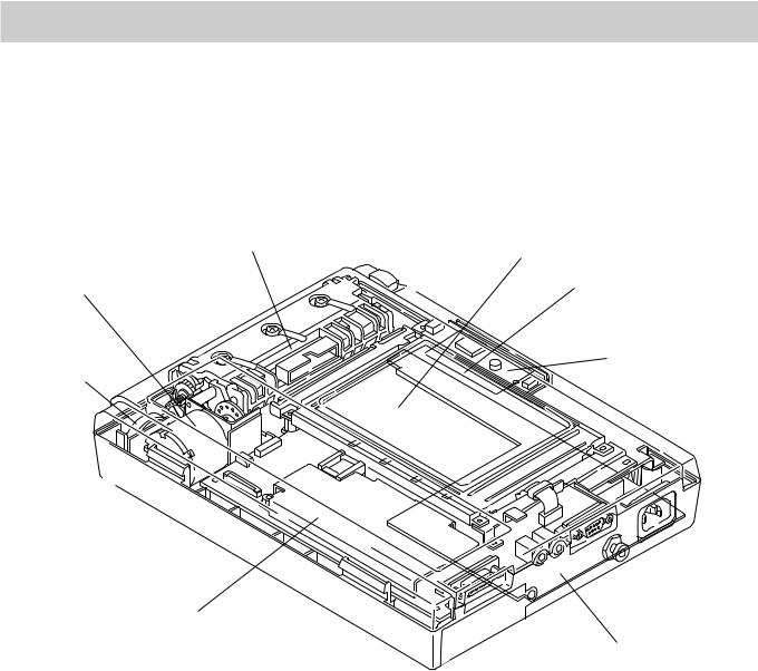
1. GENERAL
Location
|
Thermal Head Assy |
LCD Assy (for ECG-9020K only) |
|
|
|
Motor Assy |
|
Flash ROM Board |
|
|
Speaker Assy |
Inverter Board |
|
(for ECG-9020K |
||
|
||
|
only) |
ECG Control Board
Power Unit
Service Manual ECG-9010/9020 Rev A |
1.13 |

1. GENERAL
Block Diagram
NOTE
The LCD module and inverter board are used for the ECG-9020K only.
|
|
|
|
|
|
|
|
|
|
|
|
|
|
|
|
|
|
|
|
Piezo-electric |
CNA011 |
|
|
|
CNJ032 (2pin) |
||||||||
|
|
|
|
|
|
|||||||||||
|
|
|
|
|
|
|
|
|
|
|
||||||
|
|
|
buzzer |
|
|
|
|
|
|
|
|
|
||||
|
|
|
|
|
|
|
|
|
|
|
|
|||||
|
|
|
|
|
|
|
|
|
|
|
|
|
|
|
|
|
|
|
|
|
|
|
|
|
|
|
|
|
|
|
|
|
|
|
|
Motor, Motor sensor, |
|
|
|
|
|
|
|
|
||||||
|
|
CNA012 |
|
|
CNJ036 (12pin) |
|||||||||||
|
|
Mark sensor |
|
|
|
|
|
|
|
|
||||||
|
|
|
|
|
|
|
|
|
|
|
||||||
|
|
|
|
|
|
|
|
|
|
|
|
|
|
|
|
|
|
|
|
|
|
|
|
|
|
|
|
|
|
|
|
|
|
|
|
|
Membrane key |
|
|
|
|
|
|
|
|
CNJ033 (40pin) |
||||
|
|
|
|
|
|
|
|
|
|
|
||||||
|
|
|
|
|
|
|
|
|
|
|||||||
|
|
|
|
|
|
|
|
|
|
|
|
|
|
|
|
|
|
|
|
|
|
|
|
|
|
|
|
|
|
|
|
|
|
|
|
|
|
|
|
|
|
|
|
|
|
|
|
|
|
|
|
|
|
LCD module |
|
|
|
|
|
|
|
|
CNJ012 (12pin) |
||||
|
|
|
|
|
|
|
|
|
|
|||||||
|
|
|
|
|
|
|
|
|
|
|
|
|
|
|
|
|
|
|
|
|
|
|
|
|
|
|
|
|
|
|
|
|
|
|
|
|
|
|
|
|
|
|
|
|
|
|
|
|
|
|
|
|
|
2 pin |
|
|
|
|
|
|
|
|
|
|
|
|
|
|
|
|
|
|
|
5 pin |
|
CNA015 |
|
|
CNJ013 (6pin) |
|||||
|
|
|
|
|
|
|
|
|
||||||||
|
|
|
Inverter board |
|
CNA013 |
|
|
|
|
|||||||
|
|
|
|
|
|
|
|
|
||||||||
|
|
|
|
|
|
|
|
|||||||||
|
|
|
|
|
|
|
|
|
|
|
|
|
||||
|
|
|
|
|
|
|
|
|
|
|
|
|
||||
|
|
|
Thermal head |
|
|
|
CNJ011 (12pin) |
|||||||||
|
|
|
|
|
|
|
|
|
|
|
|
|||||
|
|
|
|
|
|
|
|
|
|
|
|
|
|
|
|
|
|
|
|
|
|
|
|
|
|
|
|
|
|
|
|
|
|
|
|
|
|
|
|
|
|
|
|
|
|
|
|
|||
|
|
|
|
|
|
|
|
|
|
|
|
|
|
|
|
|
|
|
|
|
|
|
|
|
|
|
|
|
|||||
|
|
|
CN11 (3pin) |
CN31 (16pin) |
|
|||||||||||
AC |
|
|
|
|
|
|
|
|
|
|
||||||
|
Power Unit (SC-903D) |
CN021 |
||||||||||||||
source |
|
|||||||||||||||
|
(30pin) |
|||||||||||||||
|
|
|
|
|
|
|
|
|
|
|
|
|
|
|
|
|
Flash ROM Board
(UT-2357)
CNJ011 (80pin)
CNJ021 (80pin)
CNJ031 (D-SUB 9pin)
ECG Control Board (UT-23561)
CNJ043 (mini jack)
CNJ041 (mini jack)
CNJ035 (30pin) |
CNJ091 (D-SUB15pin) |
SIO
EXT-IN
CRO
Patient Input
CN51 (4pin)
CNA014
Battery
1.14 |
Service Manual ECG-9010/9020 Rev A |

1. GENERAL
Connection Diagram
Index |
Connector No. |
NK Code No. |
Description |
1* |
CNA011 |
543993A |
ZHR-2 speaker cable (L50) |
2 |
CNA012 |
544002A |
ZHR-12 motor cable (L120, 65) |
3 |
CNA013 |
544029B |
FCN723/DF11(100)/51021(40) |
4 |
CNA014 |
544011A |
EHR-4 battery terminal cable (L150) |
5 |
CNA015 |
544038A |
51021-0500/51021-0600 (L50) |
*We cannot provide this cable seperately; we can only provide it as part of a complete Speaker assy. Refer to “Speaker Assy” in Section 8.
® CNA013
- CNA012
° CNA015
¬ CNA011
¯ CNA014
Service Manual ECG-9010/9020 Rev A |
1.15 |
Section 2 Maintenance
Replacement ...................................................................................................................... |
2.1 |
Periodic Replacement Schedule .............................................................................. |
2.1 |
Cleaning ............................................................................................................................. |
2.2 |
Cleaning and Greasing Schedules .......................................................................... |
2.2 |
Cleaning the Paper Mark Sensor and Paper Empty Sensor .................................... |
2.2 |
Cleaning the Motor Rotation Sensor and |
|
Greasing the Motor Gear and Gear Meshed with Motor Gear ................................. |
2.3 |
Service Manual ECG-9010/9020 Rev A |
2C.1 |

2. MAINTENANCE
This section describes the periodic replacement and cleaning of parts which are required to maintain the instrument in good working condition.
Replacement
This subsection only describes replacement schedule for parts that need to be periodically replaced. The actual replacement procedures are described in the section for Disassembly and Assembly. Read the whole “Disassembly and Assembly” section, especially its Warnings and Cautions, before replacing any of the parts described here.
Periodic Replacement
Schedule
To maintain the performance of the instrument, the parts listed in the table below must be periodically replaced by qualified service personnel.
Part |
NK Code No. Description Recommendation |
LCT-1912ANK |
332543B |
KPT-104-8MGF1-NKC 541816 |
|
LM32019T |
545946 |
Motor ASSY |
GC-0011 |
BR2032/1F2 |
390765 |
Battery |
* See below. |
Thermal head |
After 30 km of |
|
recording |
LCD Module |
After 10000 hours |
Motor ASSY |
After 1000 hours |
Lithium battery ** See below.
*Replace the battery when it cannot last for 30 minutes during battery operation at the temperatures between 20 and30° C.
**Replace the lithium battery on the ECG control board when the No. 08 or 09 system error message appears or after the lithium battery is used for 7 years. The life time of the battery is approx. 7 years.
Service Manual ECG-9010/9020 Rev A |
2.1 |

2. MAINTENANCE
Cleaning and Greasing
Cleaning and Greasing
Schedules
Cleaning the Paper Mark
Sensor and Paper Empty
Sensor
This subsection describes the cleaning and greasing procedures for parts that must be cleaned and greased by qualified service personnel. The cleaning procedures for parts that can be cleaned by the user are described in the Operator’s Manual.
To maintain the performance of the instrument, the parts listed in the table below must be regularly cleaned or greased.
Part |
Frequency |
Performed by |
Instrument (external) |
After each use |
User |
Thermal Head |
Once a month |
User |
Platen Roller assy |
Once a year |
User |
Paper Mark Detection Sensor |
Once a month |
Qualified service personnel |
Paper Empty Sensor |
Once a month |
Qualified service personnel |
Motor Sensor |
Once a year |
Qualified service personnel |
Motor Gear and Gear |
Once a year |
Qualified service personnel |
Meshed with Motor Gear |
|
|
1.Remove the magazine. The illustration below shows the location of the paper mark sensor and paper empty sensor.
2.Use a piece of cotton moistened with alcohol to clean both sensors.
Paper mark sensor
Paper empty sensor
2.2 |
Service Manual ECG-9010/9020 Rev A |
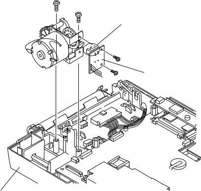
Cleaning the Motor Rotation Sensor and Greasing the Motor Gear and Gear Meshed with Motor Gear
2. MAINTENANCE
1.Detach the top casing from the bottom casing as described in the “Disassembly and Assembly” section.
2.Remove the two screws holding the motor assy to the bottom casing and remove the motor assy.
3.Remove the two screws to expose the motor rotation sensor and photodiode.
Motor assy |
Motor rotation sensor and |
|
photodiode |
Motor SENS board
Bottom casing
4.Use a piece of cotton moistened with alcohol to clean the sensor and photodiode.
5.Use a brush to clean the holes in the gear.
Service Manual ECG-9010/9020 Rev A |
2.3 |
2. MAINTENANCE
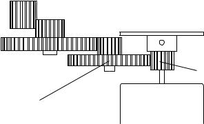
6.Use EM-50L (NK code No. 547712) grease to grease the motor gear and the gear which directly meshes with the motor gear as shown below.
Top view
Motor gear
Gear meshed |
Motor |
with motor gear |
|
7.Reattach the MOTOR SENS board to the motor with the two screws.
8.Reattach the motor assy to the bottom casing with the two screws.
9.Reattach the top casing to the bottom casing as described in the “Disassembly and Assembly” section.
2.4 |
Service Manual ECG-9010/9020 Rev A |
Section 3 Troubleshooting and
System Error Message
Troubleshooting Flowchart ................................................................................................. |
3.1 |
Troubleshooting Table......................................................................................................... |
3.4 |
Troubleshooting General Operation Problem ........................................................... |
3.4 |
Troubleshooting Recording Problem ........................................................................ |
3.6 |
System Error Message ...................................................................................................... |
3.7 |
Service Manual ECG-9010/9020 Rev A |
3C.1 |
Loading...