

Nieco 952E, 932E, 922E User Manual

AUTOMATIC
FOODSERVICE
EQUIPMENT
AUTOMATIC ELECTRIC BROILER
MODELS 952E, 932E and 922E
OWNER’S MANUAL
IMPORTANT: RETAIN THIS MANUAL IN A SAFE PLACE FOR FUTURE REFERENCE.
Broiler area must be kept free of combustible materials, and the flow of combustion and ventilation air must not
be obstructed. Operating personnel must not perform any maintenance or repair functions. Contact your Nieco
Authorized Dealer.
FOR YOUR SAFETY:
Do not store or use gasoline or other flammable vapors or
liquids in the vicinity of this or any other appliance.

2

3
TABLE OF CONTENTS
A. Machine Installation.....................................................................................................................4
Pre-Installation
Mounting
Hood Requirements
Clearance
Electrical Connection
Pre-Operation Check
B. Operation......................................................................................................................................5
Controls and Indicators
Broil Temperature Stabilizer Control
Step-by-Step Starting Procedure
Shutdown Procedure
C. Parts and Location.......................................................................................................................8
952
932
922
D. Cleaning........................................................................................................................................17
E. Periodic Maintenance ..................................................................................................................17
F. Conveyor Belt Removal
...............................................................................................................18
G. Conveyor Belt Tension................................................................................................................19
Broil Belt Problems
H. Trouble Shooting Guide..............................................................................................................20
I. Wiring Diagrams
..........................................................................................................................22

4
A. INSTALLATION
PRE-INSTALLATION
Uncrate the broiler, and inspect for shipping damage. Contact the factory if there is obvious damage. Remove
the tape securing the machine parts, and install the parts in their proper location. Refer to the Parts and
Location section of this manual. If you find concealed damage to any part of this unit, contact your freight carrier immediately. The factory warranty does not cover freight damage.
MOUNTING
If the broiler was shipped with a tubular stand, refer to seperate tubular stand assembly instructions.
Note: The four legs of the broiler stand are equipped with casters. Always set the brakes on the casters to prevent the broiler from shifting during operation or cleaning.
HOOD REQUIREMENTS
This appliance must be installed under a ventilation hood of adequate size and capacity (approximately 600
CFM). The hood should be at least 6" larger in all dimensions than the appliance top, and be 12" to 18" above
the top. Do not obstruct the flow of combustion and ventilation air. An adequate air supply must be available
for safe and proper operation.
Note: See the National Fire Prevention Association booklet on ventilation of cooking equipment. Write
to: NFPA, 470 Atlantic Ave., Boston, MA 02210. Local codes on venting must also be complied with.
CLEARANCE
For proper installation, the minimum clearance from combustible and non-combustible construction is 6" from
the back and 6" from the front of the machine. Keep appliance area free from combustibles.
To facilitate disassembly and service of the unit a minimum of 24" should be allowed on the control panel
(right) side of the broiler, as well as in front of the broiler.
ELECTRICAL CONNECTION
Power requirements are stated on the unit nameplate and must be connected accordingly. Before starting
broiler, tighten all electrical connections in control box.
Note: This appliance must be electrically grounded in accordance with local codes or in the absence
of local codes, the National Electrical Code, ANSI/NFPA No. 70-1990. In Canada, in accordance with
the Canadian Electrical Code CSA 22.1 part 1, or local codes.
WARNING: This appliance should be connected with a five-pronged grounding plug for your
protection against shock hazard. Be sure to plug directly into a properly grounded five-prong
receptacle. Do not cut or remove grounding prong from plug.
Note:
This appliance cannot be safely operated in the event of a power failure. No attempt should be
made to operate during a power failure. Disconnect power supply before servicing.
PRE-OPERATION CHECK
Be sure that all parts are installed in the proper location. Refer to OPERATION section for lighting procedure.
Start broiler and test for proper operation.
5
B. OPERATION
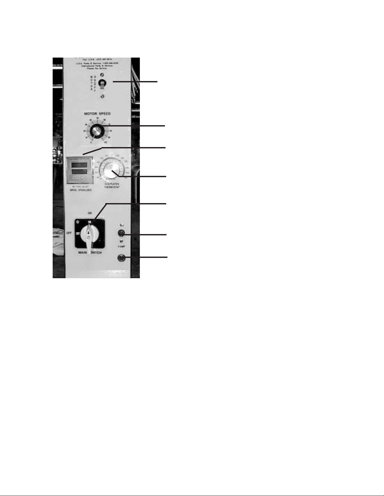
CONTROLS AND INDICATORS
(Note: Controls for the 922E are in a slightly different position)
Motor Breaker Switch
Motor Speed Control - adjusts the speed of the conveyor belt.
Broil Temperature Stabilizer Control:
Top Number = Actual Temperature
Bottom Number = Set Temperature
Meat Holding Unit Temperature Control. (Use a setting of 200°
F to start)
Main Power Switch
Fuse - 5 amp
Power on indicator light.
After the hamburgers are cooked, they drop into the Holding Unit, which uses an electrically heated base to
maintain a set temperature for holding the hamburgers or chicken.

6
BROIL TEMPERATURE STABILIZER CONTROL
The Models 952, 932E & 922E are equipped with a Broil Temperature Stabilizer Control that
senses when the broiler is being used, and adjusts the temperature to keep the broiler hot during heavy use. The control consists of two parts - a temperature probe to sense the internal
temperature of the broiler, and the control itself.
CALIBRATING THE BROIL STABILIZER CONTROL
In order to assure proper operation, the Broil Stabilizer Control must be calibrated for operation
in the restaurant. Every broiler will calibrate slightly differently, depending on supply voltage,
ventilation, etc. Follow these step by step instructions when the broiler is new, and once per
month after.
Step 1: Be sure all pieces of the broiler are in place. Make sure the broiler is plugged in and
the exhaust hood is turned on. Turn the broiler on by turning the main power switch to
the right. Turn on the conveyor belts using the motor breaker switch.
Step 2: Set the temperature (bottom number) to 200° F. Use the up or down arrows on the con-
trol to set the temperature. The bottom number is the set temperature and the top number is the actual temperature.
Step 3: Allow the broiler to heat up for 40 minutes. During this time, the actual temperature will
climb. Wait until the actual temperature stabilizes before proceeding.
Step 4: Set the ATC (bottom number) to 200° F higher than the actual temperature. For exam-
ple, if the broiler stabilizes at 700° F, then the proper setting should be 900° F.
WARNING
The broiler can be damaged if this control is not set according to instructions.
TROUBLE SHOOTING ERROR MESSAGES
Message Action
ER 4 Turn power on and off several times. If the message remains, replace control. If
the message disappears, the control may need to be reprogrammed. Call Nieco
or your local distributor for instructions.
ER 6 Cycle power on and off several times. If message remains, replace temperature
probe (P/N 4073).
7
Before starting broiler, ensure that all parts are installed in the proper location, and the ventilation hood is turned on.
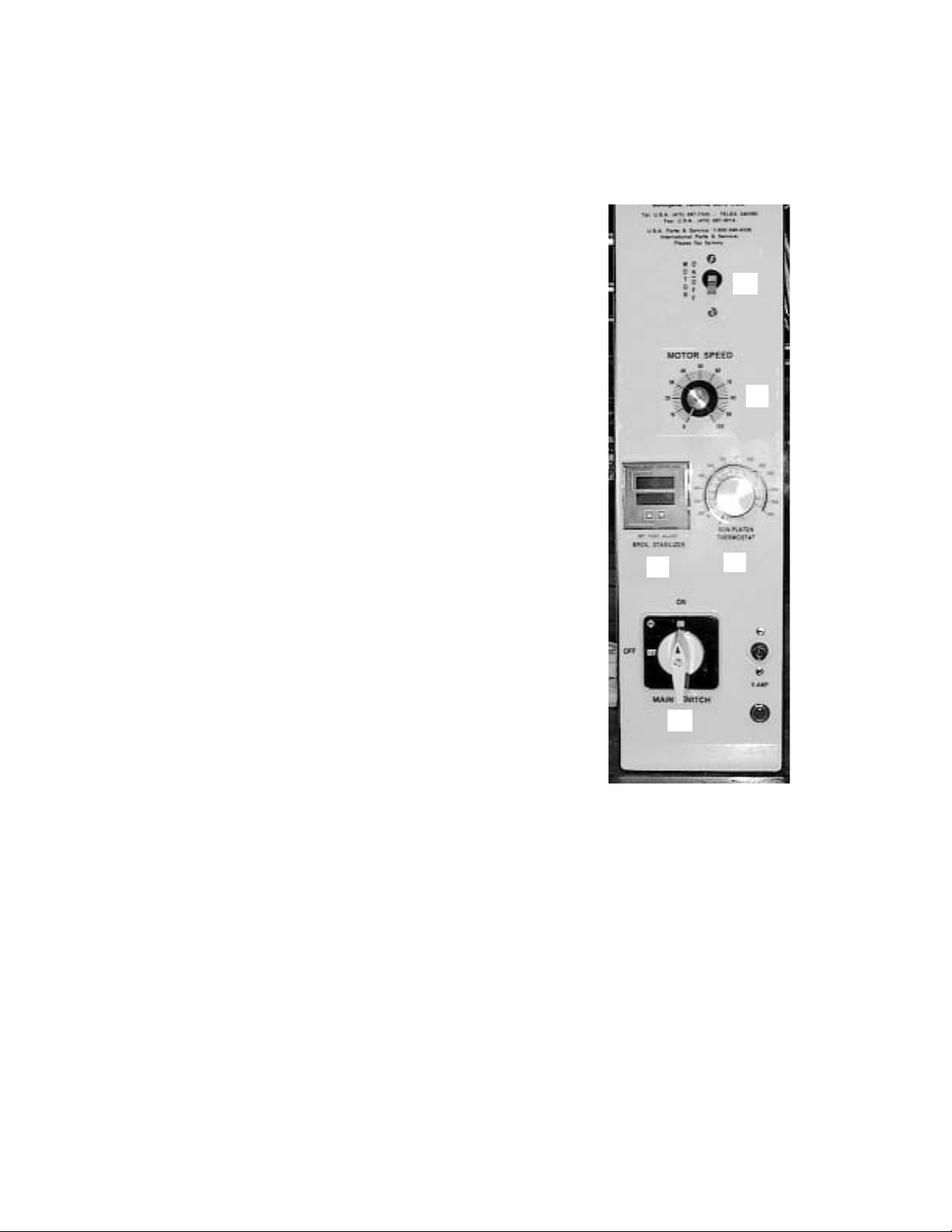
STEP-BY-STEP STARTING PROCEDURE
1. Turn on Main Power by turning the Main
Power Switch (A) to the right.
2. Turn on Motor Power Switch (B) and set
Motor Speed Control (C) to desired setting. (Use a setting of “50” to start.)
3. Check the Broil Temperature Stabilizer
(D). Daily setting should not be necessary.
Top Number = Actual Temperature
Bottom Number = Set Temperature
4. Set the temperature on the holding section (E). Use a setting of 200° F to start.
Recommended maximum holding time is 10
minutes.
SHUTDOWN PROCEDURE
For EMERGENCY Shutdown, turn the Main Power Switch off. Rotate the switch to the left.
For planned shutdowns, perform the following procedure:
1. Clear machine of all food products.
2. Turn Main Power Switch off.
3. Turn Motor Switch off.
CAUTION: Always turn machine completely off before unplugging power cord.
CAUTION: Allow machine to cool before removing any parts.
A
B
C
D
E
8
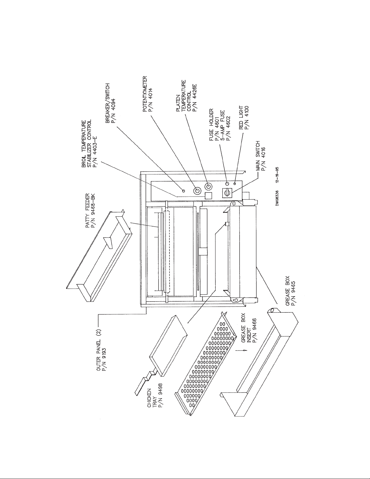
C. PARTS AND LOCATION
Model 952 Electric - Feed End View
9
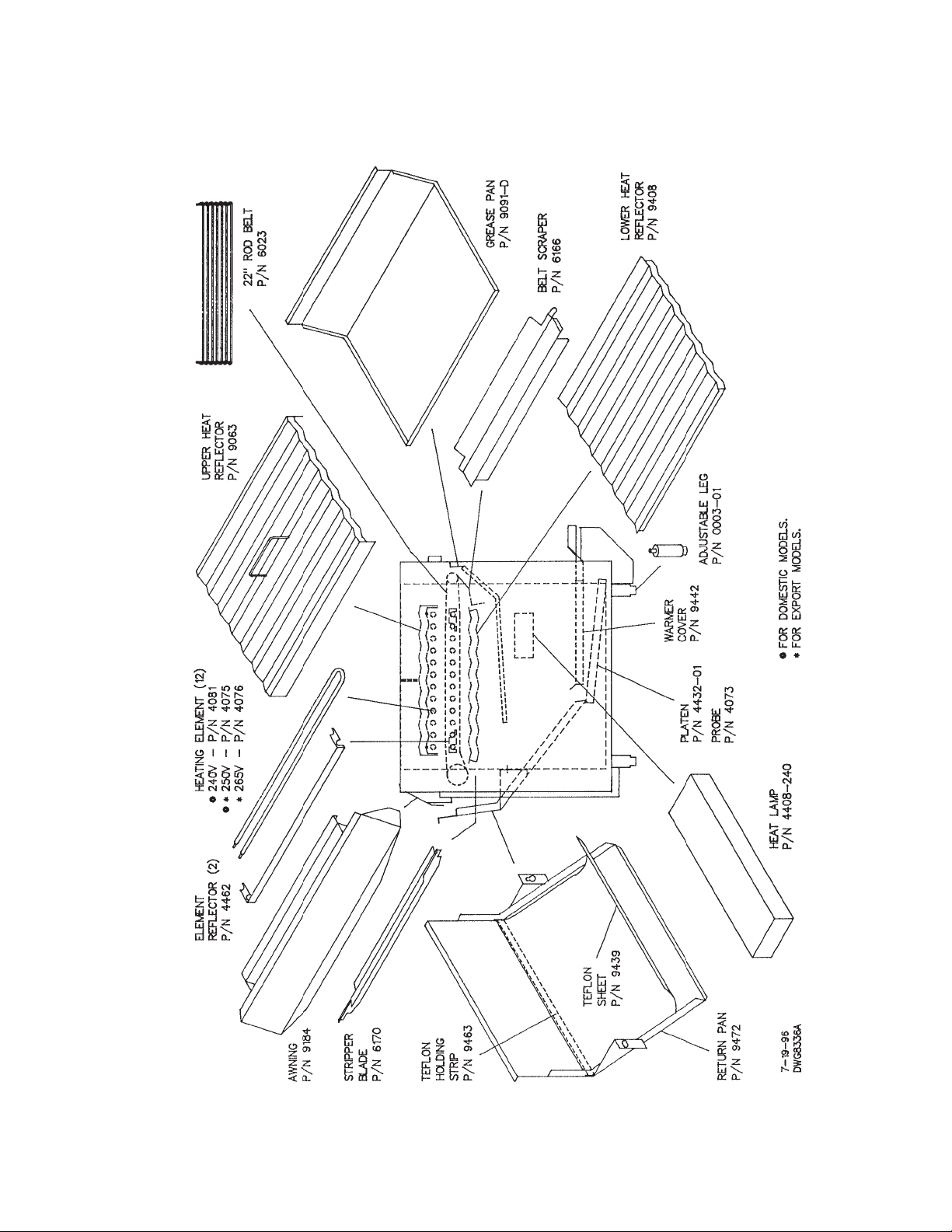
C. PARTS AND LOCATION
Model 952 Electric - Left Side View
 Loading...