

Nieco 815E Installation Manual

AUTOMATIC
FOODSERVICE
EQUIPMENT
FLEXI-CHEF SYSTEM
®
AUTOMATIC ELECTRIC BROILER
MODEL 815E
OWNER’S MANUAL
IMPORTANT: RETAIN THIS MANUAL IN A SAFE PLACE FOR FUTURE REFERENCE.
Broiler area must be kept free of combustible materials, and the flow of combustion and ventilation air
must not be obstructed. Operating personnel must not perform any maintenance or repair functions.
Contact your Nieco Authorized Dealer.
FOR YOUR SAFETY:
Do not store or use gasoline or other flammable vapors or
liquids in the vicinity of this or any other appliance.

2
TABLE OF CONTENTS
A. General Information.......................................................................................................3
Description
Food Preparation
B. Machine Installation.......................................................................................................4
Pre-Installation
Mounting
Hood Requirements
Clearance
Electrical Connection
Pre-Operation Check
C. Operation........................................................................................................................5
Controls and Indicators
Starting Procedure
Shutdown Procedure
D. Replacement Parts List .................................................................................................6
E. Parts and Location.........................................................................................................7
F. Assembly/Disassembly and Cleaning
..........................................................................9
Condensed Cleaning Instructions
Maintenance
G. Conveyor Belt Removal.................................................................................................13
H. Conveyor Belt Tension
..................................................................................................15
Broil Belt Problems
I. Trouble Shooting Guide.................................................................................................16
J. Specifications
.................................................................................................................17
K. Wiring Diagram
...............................................................................................................18
3
A. GENERAL INFORMATION
MODEL 815E
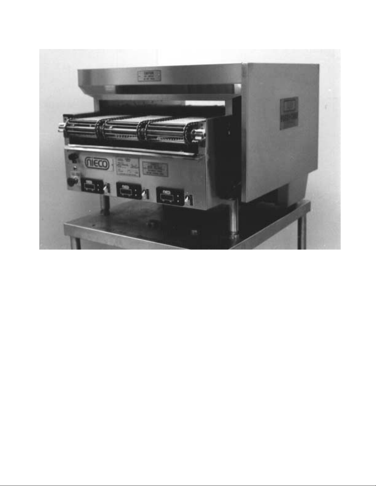
DESCRIPTION
The Nieco Model 815E is an electrically heated conveyorized radiant broiler. Elements on the top
and bottom of the conveyor belts cook a wide variety of products quickly and consistently. The
815E can be equipped with up to three independently controlled cooking belts.
Backed by the Nieco worldwide distributor network, your 815E and all other Nieco equipment
comes with a full service system that provides on-time delivery, start-up, and training assistance,
as well as 24 hour help, should you ever need it.
FOOD PREPARATION
In order to cook properly on the 815E, the operator must prepare the food in a consistent and
appropriate manner. The portions need to be uniform, the product temperature going into the
broiler must be consistent, and if pans or plates are used to cook on, they must be the same.
In automating the kitchen, individual portions of each dish are prepared for cooking in advance of
demand. Items to be broiled are cut into appropriate portions, and held in a refrigerator until needed. Some products, such as hamburgers can be frozen and do not have to be thawed before broiling.

4
B. INSTALLATION
PRE-INSTALLATION
Uncrate the broiler, and inspect for shipping damage. Contact the factory if there is obvious damage. Remove the
tape securing the machine parts, and install the parts in their proper location. Refer to the Parts and Location section
of this manual. If you find concealed damage to any part of this unit, contact your freight carrier immediately. The factory warranty does not cover freight damage.
MOUNTING
If the broiler was shipped with a tubular stand, refer to separate tubular stand assembly instructions.
Note: The four legs of the broiler stand are equipped with casters. Always set the brakes on the casters to
prevent the broiler from shifting during operation or cleaning.
HOOD REQUIREMENTS
This appliance must be installed under a ventilation hood of adequate size and capacity (approximately 600 CFM).
The hood should be at least 6" larger in all dimensions than the appliance top, and be 12" to 18" above the top. Do
not obstruct the flow of combustion and ventilation air. An adequate air supply must be available for safe and proper
operation.
Note: See the National Fire Prevention Association booklet on ventilation of cooking equipment. Write to:
NFPA, 470 Atlantic Ave., Boston, MA 02210. Local codes on venting must also be complied with.
CLEARANCE
For proper installation, the minimum clearance from combustible and non-combustible construction is 6" from the
back and 6" from the front of the machine. Keep appliance area free from combustibles.
To facilitate disassembly and service of the unit a minimum of 24" should be allowed on each end of the broiler to
allow the drip trays and reflectors to be removed.
ELECTRICAL CONNECTION
Power requirements are stated on the unit nameplate and must be connected accordingly. Before starting broiler,
tighten all electrical connections in control box.
Note: This appliance must be electrically grounded in accordance with local codes or in the absence of local
codes, the National Electrical Code, ANSI/NFPA No. 70-1990. In Canada, in accordance with the Canadian
Electrical Code CSA 22.1 part 1, or local codes.
WARNING: This appliance should be connected with a five-wire (3 phase, neutral, ground) plug for
your protection against shock hazard. Be sure to plug directly into a properly grounded five-prong
receptacle. Do not cut or remove grounding prong from plug.
Note:
This appliance cannot be safely operated in the event of a power failure. No attempt should be made
to operate during a power failure. Disconnect power supply before servicing.
PRE-OPERATION CHECK
Be sure that all parts are installed in the proper location. Refer to OPERATION section for starting procedure. Start
broiler and test for proper operation.
5
C. OPERATION
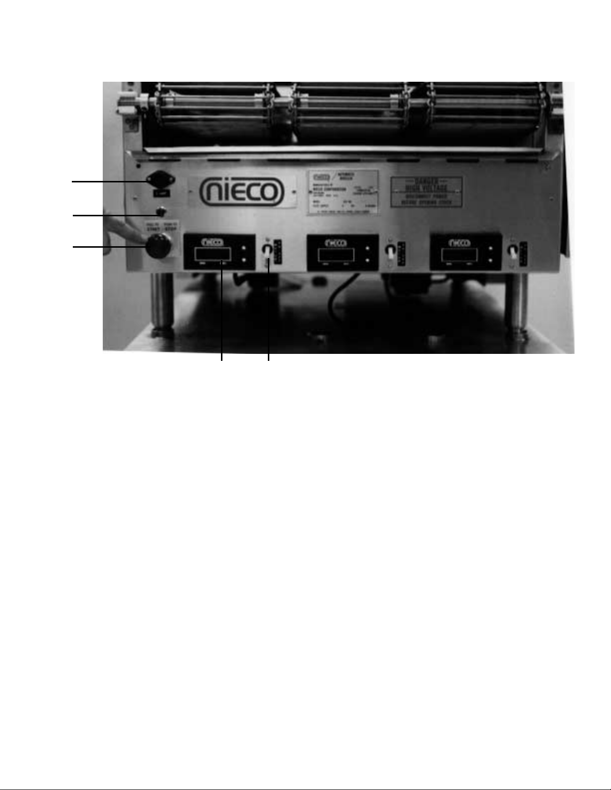
CONTROLS AND INDICATORS
A. 5 Amp fuse D. Digital Speed Controller (3)
B. Power On Indicator Light (Red) E. Motor On/Off Switches (White) (3)
C. Main Power On/Off Switch (Red)
STARTING PROCEDURE
Before starting broiler, ensure that all parts are installed in the proper location, the plug is properly
inserted in the socket, and the ventilation hood is turned on.
1. Turn on the power to the broiler by pulling out the red On/Off switch (C).
2. Turn on the motor switches (E) and set the cook times on the digital speed controller (D).
SHUTDOWN PROCEDURE
For EMERGENCY Shutdown, turn the Main Power Switch off. (PUSH Red Switch in.)
For planned shutdowns, perform the following procedure:
1. Clear machine of all food products.
2. Turn Main Power Switch off.
3. Turn Motor Switches off.
CAUTION: Always turn machine completely off before unplugging power cord.
CAUTION: Allow machine to cool before removing any parts.
A
B
C
DE

6
D. REPLACEMENT PARTS LIST
MODEL 815E
PART NO. DESCRIPTION
0005 6” Adjustable Legs
4022 208V Heating Element
4031 230V Heating Element
4056 50A Circuit Breaker
4067 Contactor
4075 250V Heating Element
4076 265V Heating Element
4081 240V Heating Element
4094 Motor Switch - green
4100 Red Indicator Light
4144-02 Carbon Brushes for 4144-05 Motor
4144-05 Drive Motor - 120V
4145-05 Drive Motor - 240V
4145-06 Carbon Brushes for 4145-05 Motor
4149 200V Heating Element
4220 Switch, Main on/off, 1Ø
4390 Element Reflector
4575 Digital Speed Controller - 120V
4576 Blue Motor Pick Up for 4575 & 4579 Speed Controllers
4579 Digital Speed Controller - 240V
4601 Fuse Holder
4602 Fuse, SC-5
6006 10T Sprocket, Motor Drive
6027 #35 Drive Chain
6038 30T Sprocket, Patty Belt
6048 Master Link, Drive Chain
6053 Offset Link, Drive Chain
6066 5/8” Teflon Bearing
6024 24” Rod Belt
6124 7” Rod Belt
6667 7” Stripper Blade
6673 24” Stripper Blade
9063 Upper Heat Reflector
9128 Shaft Cleaning Tool
9301 Side Panel
9302 Discharge Pan
9322 Discharge Pan Shield
9326-E Awning, Discharge End
9327-E Awning, Feed End
9331 Front Drip Pan
9332 Drip Tray
9345 Grease Collection Box
9362 Insert, Discharge Pan
9372 Discharge Shelf
9395 Feed End Hanging Shield
9408 Lower Heat Reflector
 Loading...