

Page 1
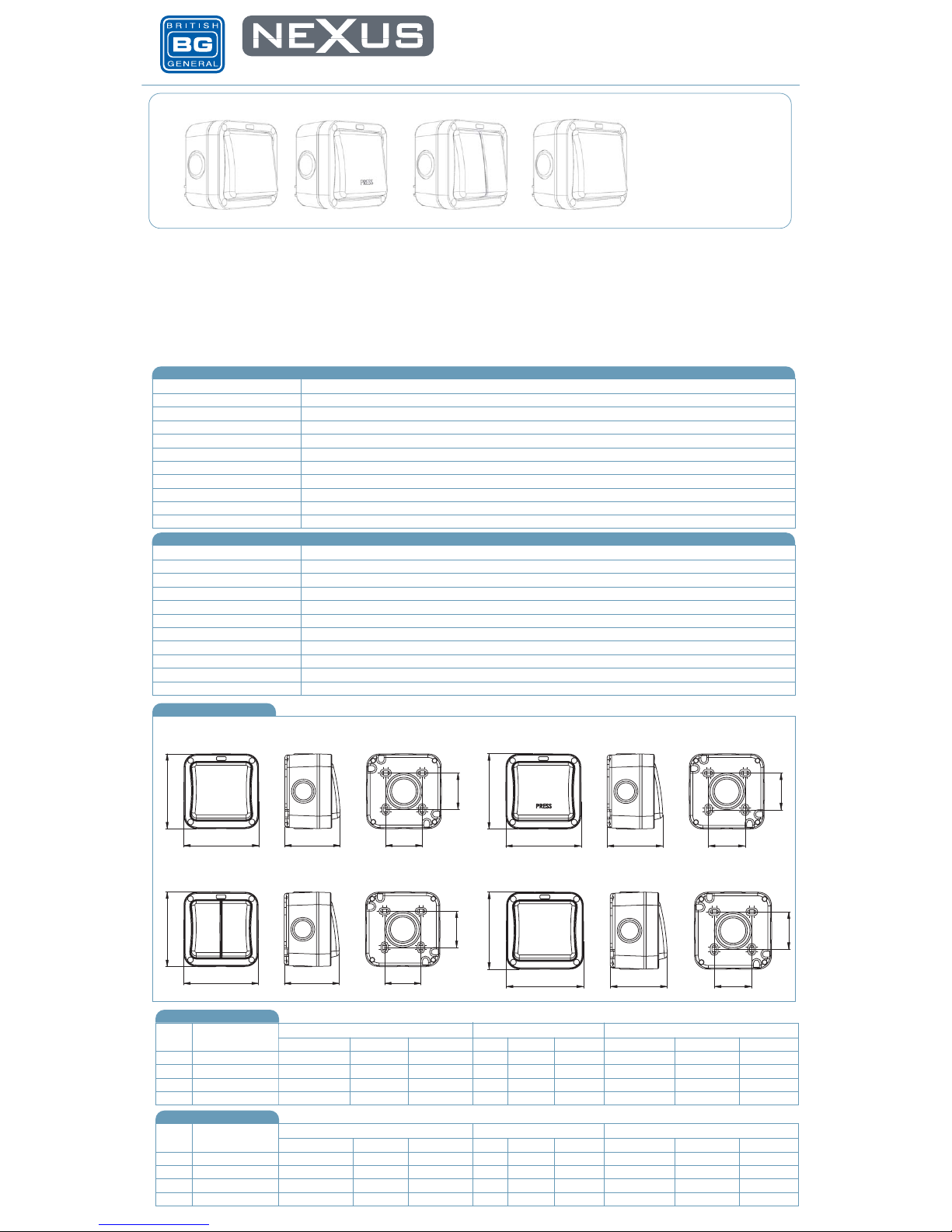
20 AMP 20AX SWITCHES
Product Images
Brief Description of Products Features
Technical Specifications ( WP12, WP14, WP42 products)
Standard(s)
IP66
3.0mm minimum
4 x 1.0mm² 4 x 1.5mm² 2 x 2.5mm² 1 x 4.0mm²
Single pole
20 Amp 250V~ (20AX - no derating for inductive or fluorescent loads)
BS EN 60669-1
No
No
91mm x 91mm x 67mm
5 x 20mm. 1 in each of 3 sides and 2 in the remaining side
1 drill out entry 20/25mm in rear face
Rating
Switch type
Contact Gap
Terminal Capacity
IP rating
Covered by RoHS directive
Covered by WEEE directive
Size
Number of 20mm cable entries
Technical Specifications ( WP30 products)
Standard(s)
IP66
3.0mm minimum
4 x 1.0mm² 4 x 1.5mm² 2 x 2.5mm² 1 x 4.0mm²
Double pole
20 Amp 250V~ (20AX - no derating for inductive or fluorescent loads)
BS EN 60669-1
No
IP66
91mm x 91mm x 67mm
5 x 20mm. 1 in each of 3 sides and 2 in the remaining side
1 drill out entry 20/25mm in rear face
Rating
Switch type
Contact Gap
Terminal Capacity
IP rating
Covered by RoHS directive
Covered by WEEE directive
Size
Number of 20mm cable entries
Line Diagrams
A range of IP rated accessories designed to protect the potentially dangerous electricity
supply in the most arduous of conditions
Clearly marked terminals with backed out captive screws for easy
installation
20 Amp, 20AX inductive rated
Covers to seal the fixing screws
Earth terminal in mounting box
All cable entries in the 4 sides have removable blanking caps.
Housing will accept alternative switch modules from the Grid range
Neon indicator that can be wired to illuminate when off or on
depending on wiring
Packaging Information
WP12 20AX 1G, 2 Way Printed Box /
/
/
/
/
/
/
/
/
/
/
/
/
/
/
/
/
/
/
/
/
/
/
/
Printed Box
Printed Box
Printed Box
20AX 2G, 2 Way
20A 1G, Double Pole
20AX 1G, 1 Way, PRESS
20AX 1G, 2 Way
20AX 2G, 2 Way
20A 1G, Double Pole
20AX 1G, 1 Way, PRESS
WP42
WP14
WP30
WP12
WP42
WP14
WP30
Cat.No Description
Packaging Type Pack Quantity Barcode
Product Inner Box Outer Box Each Inner Box Outer Box Individual Inner Box Outer Box
Weights and Dimensions
Cat.No Description
Dimension ( W x L X H ) unit : cm Weight (g) CBM (m³)
Product Inner Box Outer Box Each Inner Box Outer Box Individual Inner Box Outer Box
WP12 WP14 WP42 WP30
WP12
WP42 WP30
WP14
6791
19
44
44
6791
19
44
44
6791
19
44
4
4
6791
1
9
44
44
Printed Outer Box 1 10 5050765022132 5050765022231
10 5050765022149 5050765022248
10 5050765022156 5050765022255
10 5050765022163 5050765022262
1
1
1
Printed Outer Box
Printed Outer Box
Printed Outer Box
10 x 7.5 x 10 40 x 22 x 12 210 0.00075
0.00075
0.00075
0.00075
0.01056
0.01056
0.01056
0.01056
250
210
210
170
200
170
180
40 x 22 x 12
40 x 22 x 12
40 x 22 x 12
10 x 7.5 x 10
10 x 7.5 x 10
10 x 7.5 x 10
Page 2
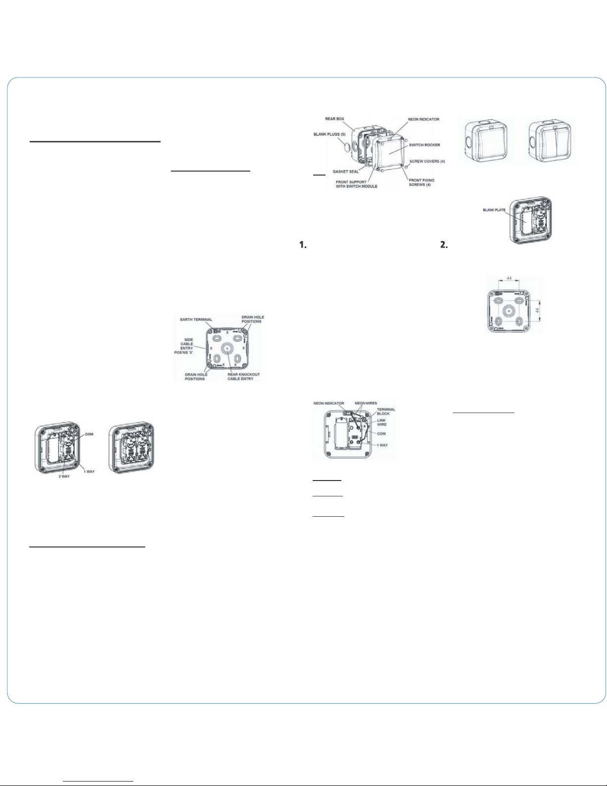
Installation Information
10. 11.8. 9.
7. Each standard Switch Module is a 2-way, single pole type & has 3 clearly
marked terminals: - COM, 2 WAY & 1 WAY as shown.
7b) For TWO WAY Switching using this Switch & another remote switch,
wire the module as follows:-
On one switch:-
Connect LIVE wire to COM terminal
Connect SWITCHED LIVE wire to 1 WAY/L1 terminal
On remote switch, using 3–core cable between switches
Connect wire core 1 between COM terminals
Connect wire core 2 between 1 WAY/L1 terminals
Connect wire core 3 between 2 WAY/L2 terminals
Note - the colours of the wires will be dependent on the type of cable used. See
Wire Identification section for reference.
If a supplied Module has been changed for another compatible Switch Module
type from the Grid range, the appropriate wiring instructions for the changed
Module must be followed.
8. The unit has Neon Indicator pre-wired between the COM terminal & terminal
block, with a Link wire to 1 WAY terminal. The Neon can be wired in one of
three ways depending on presence of Neutral supply.
1. Power Mode: Neon ALWAYS ON when POWER is ON.
2. Switch Mode: Neon ONLY ON when switch is ON.
3. Locator Mode: Neon ONLY ON when switch is OFF.
7a) For ONE WAY Switching, wire the module as follows:-
Connect LIVE wire to COM terminal
Connect SWITCHED LIVE wire to 1 WAY terminal
Locator Mode:
If Neutral supply wire is NOT present the indicator can ONLY be wired in this
mode, which is pre-wired configuration. In this case,
ensure pre-wired connections are as diagram above
Note – 2 Gang switch ONLY
For Locator & Switch Modes the Neon can ONLY be wired to
work with one switch, it CAN NOT function with both switches.
9. Ensure all terminal screws are tight & all wires are neatly routed & not unduly
stretched or pinched.
10. Any earth connections MUST be made & continuity maintained.
11. Where any earth conductor is a bare wire, it MUST be sleeved with
green/Yellow sleeving.
12. After wiring Switch, refit Front Support onto Rear Box using fixing screws –
DO NOT OVERTIGHTEN. Ensure the Gasket Seal is properly fitted over front
edge of Rear Box before tightening screws.
13. Fit Screw Covers to complete installation.
14. Switch power back on & check Switch is working. The product is now ready
to use.
15. During life of product, any cleaning should only be carried out with a damp
cloth using a mild solution of detergent & warm water. DO NOT USE solvent
based cleaners as these may cause damage.
All other connections should be as section 7.
1 gang switch 2 gang switch
Power Mode:
Switch Mode:
Discard Link wire & connect Neutral wire to terminal block
Discard Link wire & connect Neutral wire to terminal block
disconnect Neon wire from COM & connect to 1 WAY terminal
If Neutral supply wire is present, the Neon Indicator can be wired in Power or
Switch Mode (or Locator Mode if required). In this case,
12. 13.
CHANGES TO BUILDING REGULATIONS – IMPORTANT!
As from 1 January 2005, any electrical work done in domestic, fixed wiring
installations in England and Wales, will have to follow new rules & changes to
the Building Regulations Part P. These rules have been introduced to help
reduce the number of deaths, injuries and fires caused by faulty installations.
The installation work may be carried out by anyone providing it is in accordance
with the Regulation standards.
Certain electrical work (non-notifiable or minor work) may be carried out
without having to use a registered electrician or notify Local Authority Building
Control, such as: -
• replacing any electrical fitting (for example, socket outlets, light fittings,
control switches)
• adding fused spurs, sockets or lights to an existing circuit (but not in a
kitchen, bathroom or outdoors)
• any repair or maintenance work
For minor work done by a non-qualified electrician, it is highly recommended it
is checked by a qualified electrician to ensure it is safe.
For all other work (notifiable or major work) a Building Regulations application
is required & it must be checked to make sure it is safe.
This may be done by either an electrician who is part of a competent person
self-certification scheme, or by notifying the Local Authority Building Control
Department who will make required arrangements.
An application must be made to the Local Authority before commencing work
such as: -
• adding a new circuit
• adding/altering any circuit in a room with water (kitchen, bathroom, etc)
• adding/altering any circuit outdoors (outdoor sockets, lights, etc)
Where work is done by a qualified electrician, they will be responsible for
checking the work, & Local Authority does not need notification.
Where a qualified electrician or Local Authority is responsible for checking the
work, they will provide a certificate or notice to confirm that the installation is
tested & safe to use.
IT IS RECOMMENDED TO USE A QUALIFIED ELECTRICIAN
If there is any doubt whether electrical work needs notification of
the Local Authority, they should be contacted first for advice.
TECHNICAL HELPLINE: 0845 194 7584
If in doubt consult a competent electrician.
SAFETY WARNING
Before use please read carefully and use in accordance with these safety wiring instructions.
Before commencing any electrical work ensure the supply is switched off at the mains.
Either by switching off the consumer unit or by removing the appropriate fuse.
Wiring should be in accordance with the latest edition of the IEE regulations (BS 7671)
6. 7.
4.
5.
Wire Identification – Twin & Earth Cable
Note - As from 1st April 2004 new colour codes for hard wire installations was
introduced.
EARTH = Green/Yellow Sleeving
NEUTRAL = BLACK (pre Apr 04) / BLUE (after Apr 04)
LIVE = RED (pre Apr 04) / BROWN (after Apr 04)
To prevent fire hazard always use cable of the correct rating, size and type for the
application.
PRODUCT APPLICATION & FEATURES
The Weatherproof Switch range comprises a robust polycarbonate enclosure
incorporating a 1 or 2 gang Grid Switch Module arrangement. It provides a
convenient & safe wall-mounted control for outdoor equipment such as lighting,
garden pond pumps, etc up to 20A current rating. Modules can be changed for
others from the Grid range such as a 20A Double Pole or retractive ‘PRESS’
switch.
The enclosure is IP66 rated in use, which means that the sealed construction
provides a very high level of protection against the ingress of both water & dust.
The Neon indicator can be used to illuminate the switch in a number of ways
depending on wiring, & presence of supply Neutral.
The Front Assembly comprises the Front Support, Switch Module(s) & Switch
Rocker(s) which is mounted to the Rear Box using 4 captive fixing screws.
A Gasket Seal is located on the front edge of Rear Box. Re-usable Blank Plugs are
pre-fitted & are pushed out from the inside. Screw Covers are provided to hide
fixings after installation.
The 1 gang Switch has one Switch Module & one wide Rocker, the 2 gang has
two Switch Modules & two half-width Rockers. The internal arrangement is
identical except 1 gang has a Blank Plate fitted in place of one Switch Module
as shown below.
WIRING & OPERATING
INSTRUCTIONS
WEATHERPROOF
20A SWITCHES
WPSWIL/A
1 gang switch – exploded view
3.
SAFETY INSTRUCTIONS – IMPORTANT
Please read ‘CHANGES TO BUILDING REGULATIONS’ (page 12)
1. An outdoor location should be chosen ensuring adequate access to a mains
supply circuit. The circuit MUST be protected by an appropriate fuse, circuit
breaker or RCD (Residual Current Device) in accordance with current IEE wiring
regulations.
2. Where conduit is used for cable runs, water condensation MUST be
prevented from collecting inside the unit & conduit. Drain holes MUST be drilled
out (see Installation Instructions)
3. If metal conduit is used, earth continuity across the conduit must be
maintained using appropriate connections (not supplied). An earth terminal in
the Rear Box is provided as required.
4. Where outdoor cable runs occur, ensure cable recommended for outdoor
installations is used. In general, rubber insulated cable & plastic M20 cable
glands can be used. Alternatively standard flat PVC twin & earth mains cable
inside 20mm plastic or metal conduit may be used. Where necessary, SWA
(Steel Wire Armoured) cable with metal cable glands should be used.
The outdoor use of unprotected flat PVC insulated cable is NOT recommended.
INSTALLATION INSTRUCTIONS
ENSURE SAFETY INSTRUCTIONS HAVE BEEN READ FIRST
The Rear Box has multiple cable entry positions on sides & one rear knockout
cable entry. One side has 2 cable entry positions. Four drain hole positions are
provided in relation to conduit positions as shown. Note position of earth
terminal.
NOTE
The drilling out of a drain hole or removing rear knock-out will reduce the IP
rating of the product.
5. To ensure continued safe & proper weatherproof operation, unused cable
entries MUST have Blank Plugs fitted.
1. The unit should be mounted on a clean, rigid vertical surface suitable to
accept screw type fixings. Surface should be reasonably flat as unevenness
could cause product damage or affect operation.
2. Undo fixing screws & remove Front Assembly from Rear Box.
3. For cable entry, decide if conduit is being used & entry positions.
For side, top or rear entry the lowermost drain hole position MUST be drilled
out using a 5mm drill. ONLY ONE drain hole position must be drilled.
For bottom entry a drain hole MUST NOT be drilled in Rear Box, but a drain hole
MUST be drilled at lowermost point of conduit run.
For rear entry, remove rear knock-out. For extra sealing protection, a channel
around knock-out is provided to accept a bead of sealant (not supplied) when
fixing to mounting surface.
4. Mount the Rear Box using No.8 screws in all four, or at least two diagonal
positions on fixing centres shown. The fixing holes are slotted to enable some
rotation adjustment if required. Fit supplied Bungs over all used fixing screw
positions to seal aperture recesses.
5. Make cable entry into Rear Box as required. Only remove Blank Plugs for
positions used. Ensure adequate excess lengths of cable for connection to
socket. Install & seal all cable glands & conduit to manufacturer’s instructions.
Ensure the Gasket Seal is properly fitted over front edge of Rear Box.
6. Offer up Front Assembly to Rear Box to determine final lengths of cables &
cut to suit. Strip outer insulation as required & then trim insulation on individual
wires 8-10mm to expose conductor ends.
1 gang switch 2 gang switch
 Loading...