


 Loading...
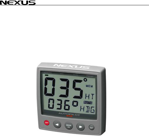
Autopilot
- Instrument -
Installation and Operation Manual
English
English

AUTOPILOT
1
AUTOPILOT
This manual is written for NX2 Autopilot version 2.01 – 2.11
Edition: March 2007
2

AUTOPILOT
1 |
Part specification.................................................................................................................... |
6 |
|
|
1.1 |
Welcome aboard!............................................................................................................ |
8 |
|
1.2 |
Capabilities ..................................................................................................................... |
8 |
|
1.3 |
Principle of operation...................................................................................................... |
8 |
|
1.4 |
Components ................................................................................................................... |
9 |
|
1.4.1 |
Autopilot instrument............................................................................................... |
9 |
|
1.4.2 |
Servo Unit (A-1500 and A-1510) ........................................................................... |
9 |
|
1.4.3 |
Rudder Angle Transmitter...................................................................................... |
9 |
|
1.1.1 |
Compass transducer ............................................................................................. |
9 |
|
1.1.2 |
Pumpset .............................................................................................................. |
10 |
|
1.1.3 |
Linear Drive ......................................................................................................... |
10 |
|
1.4.4 |
Solenoid Valve Drive ........................................................................................... |
10 |
|
1.5 |
Registering this product................................................................................................ |
10 |
|
1.6 |
About this manual......................................................................................................... |
10 |
2 |
Installation............................................................................................................................. |
11 |
|
|
2.1 |
Installing the instrument................................................................................................ |
12 |
|
2.1.1 |
Installing instrument to the Server ....................................................................... |
13 |
3 |
First start ............................................................................................................................... |
14 |
|
|
3.1 |
Initialising the instrument in a Nexus Network.............................................................. |
14 |
|
3.2 |
Re-initialising the instrument ........................................................................................ |
14 |
4 |
Operation............................................................................................................................... |
16 |
|
|
4.1 |
Instrument overview...................................................................................................... |
16 |
|
4.1.1 |
Instrument display................................................................................................ |
16 |
|
4.1.2 |
Instrument pages and functions .......................................................................... |
16 |
|
4.1.3 |
Instrument modes................................................................................................ |
16 |
|
1.1.4 |
Instrument power on/off ....................................................................................... |
17 |
|
4.2 |
How to use the push-buttons........................................................................................ |
17 |
|
4.2.1 |
MODE.................................................................................................................. |
17 |
|
4.2.2 |
LEFT.................................................................................................................... |
17 |
|
4.2.3 |
RIGHT.................................................................................................................. |
17 |
|
4.2.4 |
SET...................................................................................................................... |
17 |
|
4.2.5 |
OFF...................................................................................................................... |
17 |
|
4.2.6 |
Tack..................................................................................................................... |
17 |
|
4.2.7 |
Setup mode ......................................................................................................... |
18 |
|
4.2.8 |
Lighting ................................................................................................................ |
18 |
5 |
Function ................................................................................................................................ |
19 |
|
|
5.1 |
Standby mode............................................................................................................... |
19 |
|
5.2 |
Autopilot mode.............................................................................................................. |
19 |
|
5.2.1 |
Activate automatic steering ................................................................................. |
19 |
|
5.2.2 |
Turn off automatic steering.................................................................................. |
19 |
|
5.2.3 |
Automatic steering by compass........................................................................... |
19 |
|
5.2.4 |
Automatic steering by navigator .......................................................................... |
20 |
|
5.2.5 |
Automatic steering by wind.................................................................................. |
20 |
|
5.2.6 |
Power steering..................................................................................................... |
22 |
|
5.2.7 |
Dodging and returning to last automatic steering function .................................. |
22 |
6 |
Setup...................................................................................................................................... |
23 |
|
|
6.1 |
Setup mode .................................................................................................................. |
23 |
|
6.1.1 |
The setup mode is divided into 4 setup groups ................................................... |
23 |
|
6.1.2 |
How to access setup mode ................................................................................. |
23 |
|
6.1.3 |
How to change a setting ...................................................................................... |
23 |
|
6.1.4 |
How to return to previous mode........................................................................... |
23 |
|
6.1.5 |
Factory default settings........................................................................................ |
23 |
|
6.2 |
Lighting setup group [Lit] .............................................................................................. |
25 |
3

|
|
|
AUTOPILOT |
|
6.3 |
Autopilot setup group [P]............................................................................................... |
25 |
|
6.3.1 |
P0, Return [RET] .................................................................................................. |
25 |
|
6.3.2 |
P1, Rudder [RUD] ................................................................................................ |
25 |
|
1.1.5 |
P2, Damping of compass heading [SEA] ............................................................. |
26 |
|
6.3.3 |
P3, Counter Rudder [CRD]................................................................................... |
26 |
|
6.3.4 |
P4, Damping of wind [WSE]................................................................................. |
26 |
|
6.3.5 |
P5, Automatic Trim Calibration [ATC] .................................................................. |
27 |
|
6.3.6 |
P6, Adaptive Control [ADC].................................................................................. |
27 |
|
6.3.7 |
P7, Automatic Pilot Calibration [APC] .................................................................. |
27 |
|
6.3.8 |
P8, Rudder Reduction Speed [RRS].................................................................... |
27 |
|
6.3.9 |
P9, Rudder angle limit [LIM]................................................................................. |
28 |
|
6.4 |
Alarm setup group [A].................................................................................................... |
28 |
|
6.4.1 |
A0, Return [RET] .................................................................................................. |
28 |
|
6.4.2 |
A1, Pilot Course Alarm [PCA] .............................................................................. |
28 |
|
6.4.3 |
A2, Timer watch alarm [TMR]............................................................................... |
28 |
|
6.4.4 |
A3, Cross Track Error alarm [XTA]....................................................................... |
28 |
|
6.4.5 |
A4, Push-button beep [KEY] ................................................................................ |
29 |
|
6.5 |
Compass setup group [C].............................................................................................. |
29 |
|
6.5.1 |
C0, Return [RET].................................................................................................. |
29 |
|
6.5.2 |
C1, Magnetic heading [MAG] ............................................................................... |
29 |
|
6.5.3 |
C2, Local magnetic variation [VAR] ..................................................................... |
29 |
|
6.5.4 |
C3, Auto-deviation [Auto DEV]............................................................................. |
29 |
|
6.5.5 |
C4, Check auto-deviation [Auto CHK].................................................................. |
30 |
|
6.5.6 |
C5, Clear auto-deviation [Auto CLR].................................................................... |
30 |
|
6.5.7 |
C6, Adjust compass alignment [ADJ]................................................................... |
31 |
7 |
Maintenance .......................................................................................................................... |
32 |
|
|
7.1 |
Instrument maintenance................................................................................................ |
32 |
|
7.2 |
Drive unit maintenance and inspection schedule.......................................................... |
32 |
8 |
Fault finding........................................................................................................................... |
33 |
|
|
8.1 |
General.......................................................................................................................... |
33 |
|
8.2 |
Symptom - Cause - Action ............................................................................................ |
33 |
|
8.3 |
Nexus Network error messages with cause and remedy .............................................. |
36 |
9 |
Specifications........................................................................................................................ |
38 |
|
|
9.1 |
Technical Specifications................................................................................................ |
38 |
|
9.1.1 |
Autopilot instrument ............................................................................................. |
38 |
|
9.1.2 |
Servo Unit A-1500................................................................................................ |
38 |
|
9.1.3 |
Servo Unit A-1510................................................................................................ |
38 |
|
9.1.4 |
Rudder Angle Transmitter .................................................................................... |
38 |
|
9.2 |
Nexus Network specification ......................................................................................... |
39 |
|
9.3 |
Accessories................................................................................................................... |
39 |
|
9.3.1 |
Autopilot instrument ............................................................................................. |
39 |
|
9.3.2 |
Nexus Remote Control instrument ....................................................................... |
39 |
|
9.3.3 |
Nexus analog Rudder Angle instrument............................................................... |
40 |
|
9.3.4 |
Nexus Multi Control instrument with Server ......................................................... |
40 |
|
9.3.5 |
External alarm buzzer .......................................................................................... |
40 |
|
9.3.6 |
NFU jog lever ....................................................................................................... |
40 |
|
9.3.7 |
Other NX2 Accessories........................................................................................ |
40 |
|
9.4 |
Abbreviations ................................................................................................................ |
43 |
10 |
Warranty ........................................................................................................................... |
46 |
|
11 |
Installation........................................................................................................................ |
48 |
|
|
11.1 |
Installation general ........................................................................................................ |
48 |
|
11.2 |
Installation alternatives.................................................................................................. |
49 |
|
11.3 |
Wire thickness............................................................................................................... |
49 |
|
11.4 |
Servo Unit...................................................................................................................... |
49 |
4

AUTOPILOT
11.4.1 |
Location of Servo Unit ......................................................................................... |
49 |
|
11.4.2 |
Installing Servo Unit............................................................................................. |
49 |
|
11.4.3 |
Connecting Servo Unit......................................................................................... |
50 |
|
11.4.4 |
Safety switch........................................................................................................ |
52 |
|
11.4.5 |
Dip switches ........................................................................................................ |
52 |
|
11.4.6 |
Trim potentiometers............................................................................................. |
52 |
|
11.4.7 |
NMEA connections .............................................................................................. |
52 |
|
11.5 |
Rudder angle transmitter .............................................................................................. |
53 |
|
11.6 |
Pumpset ....................................................................................................................... |
53 |
|
11.7 |
Linear drive................................................................................................................... |
53 |
|
11.8 |
Solenoid valve controlled pumpset............................................................................... |
55 |
|
11.9 |
Other Accessories ........................................................................................................ |
55 |
|
12 |
Dockside Testing ............................................................................................................ |
56 |
|
12.1 |
Preparations ................................................................................................................. |
56 |
|
12.2 |
Dockside First Start ...................................................................................................... |
56 |
|
12.3 |
How to remove air from system .................................................................................... |
56 |
|
13 |
Sea Trials ......................................................................................................................... |
57 |
|
13.1 |
Preparations ................................................................................................................. |
57 |
|
13.2 |
Compass calibration ..................................................................................................... |
57 |
|
13.3 |
Automatic Pilot Calibration [APC] ................................................................................. |
57 |
|
14 |
Fine tuning....................................................................................................................... |
59 |
|
5

AUTOPILOT
1 Part specification
___________________________________________________________
Items delivered with the instrument
1 |
NX2 Autopilot instrument |
4 |
1 |
Instrument cover |
5 |
5 |
Cable protectors, 0,25 mm (0.1 inch) |
6 |
5 |
Cable protectors, 0,75 mm (0.3 inch) |
6 |
4 |
Instrument mounting screws |
7 |
4 |
Rubber caps for screws |
7 |
1 |
Connection back cover |
7 |
1 |
4-pole jack plug |
7 |
1 |
Silicon paste tube |
7 |
2 |
Plastic cable strap |
7 |
1 |
Adhesive drill template for instrument |
8 |
1 |
Nexus Network cable, 8 m (26 ft) |
9 |
1 |
Quick guide laminated |
10 |
1 |
Inter-connection cable, 0,3 m (1 ft ) |
|
1 |
Installation and Operating manual |
11 |
1 |
Warranty card |
12 |
1 |
National distributor list |
13 |
Registering this product
Once you have checked that you have all the listed parts, please take time to fill in the warranty document and return it to your national distributor.
By returning the warranty card, it will assist your distributor to give you prompt and expert attention. Keep your proof of purchase. Also, your details are added to our customer database so that you automatically receive new product catalogues when they are released.
Warranty conditions see 16.
6

AUTOPILOT
7

AUTOPILOT
1.1Welcome aboard!
Thank you for choosing a Nexus Autopilot. Through this manual we would like to help you install and operate your Nexus product. We are convinced that you will appreciate the useful functions. To get the most out of your Nexus product, please read through this manual carefully before you start your installation. If you see us at a show, please stop by and say hello.
Good luck and happy boating!
1.2Capabilities
Accuracy, reliability and simplicity of use, are key features of the Nexus microprocessor controlled Autopilot. Whether the need is for minimised fuel consumption, improved navigational accuracy or simply more enjoyable yachting, the Nexus Autopilot is the right navigational aid to provide precision steering under all sea conditions. Due to the very stable fluid dampened compass with high gimbaling angles and automatic trim feature, this Autopilot is suitable for sailing and powerboats. User adjustable settings make it possible to fine tune each boat, yet factory default settings and automatic calibration allow simple operation with minimal operator input.
The Nexus Autopilot is capable of operating either as a "Stand Alone" Autopilot, or as a "Network" application by connecting it to the Nexus Network. Many options are available, including GPS and wind transducers, Nexus Remote Control instrument and other Nexus digital and analog instruments.
The Autopilot Servo Unit A-1500 is designed for sailing and power boats from 35 ft. (11 m.) to over 160 ft. (50 m.), depending on drive units used. Hydraulic drive units provide precise control with low power consumption. Connection can also be made to solenoid valves of electro-hydraulic steering systems, allowing use on very large boats. Hydraulic linear drives provide powerful and accurate control when connected to mechanical steering systems and also provide independent hydraulic steering for added safety.
The Autopilot Servo Unit A-1510 is designed for sailing and power boats from 26 ft. (8 m.) to over 50 ft. (15 m.), depending on drive units used. Hydraulic drive units provide precise control with low power consumption. Hydraulic linear drives provide powerful and accurate control when connected to mechanical steering systems and also provide independent hydraulic steering for added safety.
Power steering through the instrument’s push-buttons may be used to avoid heavy wheel effort when manoeuvring. Alarms for off course, off track or watch alarm are included with provision for an optional external alarm buzzer.
1.3Principle of operation
Any difference between the set and actual course, is compared along with rate of change and trends in change*, to drive the pumpset motor or solenoid valve. The ,
8

AUTOPILOT
rudder is moved as necessary to return the boat back on course. The sensitivity to course errors andamount of correction are user adjustable to suit different boats under various sea conditions.
NB * (PID control, terminology as known by control technicians,
P = proportional part, I = integral part and D = derived part)
Factory default settings and automatic calibration, establish a basis for normal steering and may be further fine tuned if necessary. During set up routines, the compass is automatically compensated and installation errors such as reversed rudder feedback and reversed pumpset wiring or piping are automatically diagnosed and corrected. During this routine also the rudder speed is automatically optimised. This greatly reduces installation set up and sea trials time while eliminating possible Autopilot malfunction.
1.4Components
1.4.1Autopilot instrument
Control and display of all Autopilot functions are provided by the Autopilot instrument. It is waterproof and may be mounted below or above deck. Multiple Autopilot instruments can be connected and the Autopilot may be activated by pressing the push-buttons of any instrument.
1.4.2Servo Unit (A-1500 and A-1510)
The Servo Unit contains the course computer and pumpset motor drive circuitry and acts as a centre for interconnecting wiring. It is splash proof and should be located centrally to minimise lengths of wiring. The powerful microprocessor in the Servo Unit accepts heading information direct from an electronic compass or gyro compass (A- 1500 only), wind transducer, navigators and compares this against the course set by the instrument and rudder.
1.4.3Rudder Angle Transmitter
The Rudder Angle Transmitter provides the Autopilot with accurate rudder position information. It is mounted near the rudder shaft and connected to the tiller arm or quadrant with an adjustable ball joint linkage.
1.1.1Compass transducer
No Autopilot can steer better than the compass stability will allow. The Nexus compass excels in this characteristic, where the liquid dampening provides for stability even at high speeds in heavy seas. The high gimbaling angle, eliminates compass disturbance with boat heeling or rolling. The compass provides a stable heading reference for the Autopilot and should be bulkhead mounted below deck near the centre of pitch and roll for maximum stability. Construction is splash proof. The Autopilot Servo Unit or the Nexus Server can re-transmit the compass heading on the NMEA output port to receivers such as radars, plotters, compass repeaters etc.
9
AUTOPILOT
1.1.2Pumpset
Various sizes and types of pumpsets can be mounted into a hydraulic steering system. The pumpset only operates when carrying out a rudder command. When the boat is on course, the pumpset motor stops. A variable speed motor drive adjusts optimal rudder speed and provides for minimum power consumption and maximising of rudder positioning accuracy.
1.1.3Linear Drive
A hydraulic linear drive is used to drive the tiller arm or quadrant of mechanical steering systems. The linear drive is driven by a pumpset. The linear drive provides a cleaner installation, being entirely below deck, and delivers more torque to the rudder than wheel driven units. In case the mechanical steering should fail, the linear drive will provide a back-up hydraulic steering.
1.4.4Solenoid Valve Drive
On larger boats the main hydraulic steering may be fitted with solenoid valve controlled power steering. In this case the Autopilot does not need to be supplied with a pumpset since the Nexus Servo Unit output can be reconfigured with its board mounted DIP switch to provide drive for steering solenoids or relays having coil voltages of 12 or 24 VDC.
1.5Registering this product
Please take time to fill in the warranty cards and return them to your national distributor.
By returning the warranty card, it will assist your expert distributor to give you prompt attention. Keep your proof of purchase. Also, your details are added to our customer database so that you automatically receive new product catalogues when they are released.
1.6About this manual
•Each time a push-button is referred to in this manual, the push-button name will appear in bold and CAPITAL letters, e.g. MODE.
•Unless otherwise stated, the push-button presses are momentary.
•Each time a function is mentioned in the text, it will be in brackets and in the same format, where possible, as displayed, e.g. [HDG] for HeaDinG.
•With the word navigator we mean a GPS, Loran or Decca instrument.
•Which instrument is navigating? By the term navigating, we mean the active instrument in which the waypoint memory is used for navigation to calculate the navigation data, i.e. BTW, DTW etc. There can only be one instrument on the Nexus Network which is keeping the waypoints in memory, but the waypoints can be reached from all instruments.
Note! We have put in a lot of effort, in order to make this manual correct and complete. However, since we have a policy of continuous improvement, some information may differ from the product functions. If you need further information, do not hesitate to contact your national distributor.
10

AUTOPILOT
2 Installation
•The installation includes 6 major steps:
1.Read the installation and operation manual.
2.Plan where to install the transducers and instruments.
3.Run the cables.
4.Install the transducers and instruments.
5.Take a break and admire your installation.
6.Learn the functions and calibrate your system.
Before you begin drilling ... think about how you can make the installation as neat and simple as your boat will allow. Plan where to position the transducers, Server and instruments. Think about leaving space for additional instruments in the future.
•A few ”do nots” you should consider:
−Do not cut the cables too short. Allow extra cable length at the Server so it
can be disconnected for inspection without having to disconnect all attached cables.
−Do not place sealant behind the display. The instrument gasket eliminates the need for sealant.
−Do not run cables in the bilge, where water can appear.
−Do not run cables close to fluorescent light sources, engine or radio transmitting equipment to avoid electrical disturbances.
−Do not rush, take your time. A neat installation is easy to do.
•The following material is needed:
Wire cutters and strippers.
Small and large Philips and small flat head screw driver.
Hole saw for the instrument clearance hole 63 mm (2½"). 5 mm (1/4") drill for the mounting holes.
Plastic cable ties
If you are doubtful about the installation, obtain the services of an experienced technician.
11
AUTOPILOT
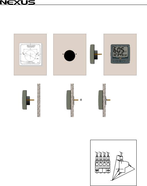
2.1Installing the instrument
•Place the adhesive drill template on the desired location for the instrument. Drill the 2 holes using a 5 mm (1/4") drill for the two pin bolts. Use a 63 mm (2½") hole saw to machine the clearance hole for the instrument connection socket. Remove the template.
•Screw the two pinbolts to the instrument
•Put the instrument in place
•Screw the two nuts from the back
Note! The two nuts must just be tighten by hand
•Run the Nexus Network cable from the Server to the instrument.
•If you want to cut the Nexus Network cable to length, disconnect 4-pole jack plug and cut the cable. Peel off about 35 mm (1,4") of the cable insulation. Remove about 6 mm (1/4") from the 3 isolated wires (the 4th wire is an earth / screen). Attach the 4 cable protectors to the wires using a pair of flat pliers.
•Connect the 4 cable protectors to the 4-pole jack plug as shown. Apply silicon paste on all locations as
shown.
Note: Must be done to avoid corrosion.
Silicon paste
12
AUTOPILOT
•Apply silicon paste to the instrument connection pins at the back of the instrument. Press the jack plug onto the instrument pins. Press the cable in to the cable leads.
•Mount the connection back cover with the screw.
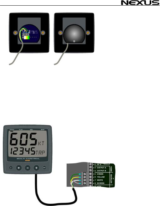
2.1.1Installing instrument to the Server
All NX2 instruments are connected directly to the Nexus Network in a daisy chain. They all use the same colour coded 4-pole jack plugs. (For instrument installation, see 2.2).
13

AUTOPILOT
3 First start
At each power on, the instrument will perform a self test. The display will first show all segments, then the software version and the Nexus Network ID number.
3.1 Initialising the instrument in a Nexus Network
At the first power on after installation, you will be asked to press SET [PrSKEY]. This will give the instrument a logical ID number from 16 and upwards on the Nexus Network.
To initialise the instrument, press SET, one instrument at a time, on all installed digital instruments,.
Warning! Always wait for the text [Init OK] to be displayed, before you press SET on the next instrument!
The Nexus Servo Unit or the Server automatically gives the first unit ID number 16, then 17 and so on. The order in which you press SET, will be the same order as the instruments will be given a logical ID number on the Nexus Network, and the same order they will be addressed by the Remote Control instrument if used.
The example shows that the instrument version number is 1.6 and the logical ID number given is 17.
Warning! Do not activate any Autopilot functions until Dockside
Testing and Sea Trials APC routine have been performed.
3.2Re-initialising the instrument
If two instruments have been given the same ID number by mistake, you must re-initialise the instruments to avoid Network disturbance and blockage of data.
To re-initialise the instrument, be prepared to press CLR during the short power up sequence, i.e. when version and ID numbers are displayed.
The display test is then re-started on all instruments and you will be asked to press SET on one instrument at the time as explained above.
Note! If you do not succeed to re-initialise, we suggest you disconnect (just pull out the connection plug) on all, except one of
14

AUTOPILOT
the instruments that had the same ID number, then re-install the instruments and repeat the above procedure.
15

|
|
AUTOPILOT |
4 Operation |
|
|
4.1 |
Instrument overview |
Top-line |
Page- |
|
|
|
Heading |
|
arrow |
|
|
Function
|
Autopilot on |
Reference |
Lower -line |
course / |
|
angle |
function text |
OFF |
|
SET |
LEFT |
MODE |
RIGHT |
4.1.1Instrument display
The display consists of two lines, a top-line with 24 mm (1”) digits and a lower-line with 13 mm (0.5”) digits.
4.1.2Instrument pages and functions
The Autopilot instrument has its functions divided into 4 pages. The page names are printed above the display:
COMPASS, NAV (Navigation), WIND and PWR ST (Power steer)
The selected function is indicated by the page-arrow at top of the display.
4.1.3Instrument modes
Standby mode: The instrument functions as a passive compass repeater. Autopilot mode: When any Autopilot function is activated.
Setup mode: It allows calibrating your Network settings.
Edit mode: It allows editing settings (when digits are flashing).
16

AUTOPILOT
1.1.4Instrument power on/off
You will switch on/off your Nexus instruments by using the instrument switch on your electrical panel as the instruments have no separate power on/off-button.
4.2How to use the push-buttons
4.2.1MODE
A press on MODE, moves one page to the right, indicated by the page-arrow at top of the display.
In edit mode, a press on MODE moves the cursor one step to the right.
It scrolls in a circular pattern, one step for every press.
4.2.2LEFT
When the Autopilot is activated, a short press on LEFT decreases the course by 1°, a long press decreases the course by 10°.
In setup mode a press on LEFT moves to the previous setup function. In edit mode a press on LEFT decreases a digit by one.
4.2.3RIGHT
When the Autopilot is activated, a short press on RIGHT increases the course by 1°, a long press increases the course by 10°..
In setup mode a press on RIGHT moves to the next setup function. In edit mode a press on RIGHT increases a digit by one.
4.2.4SET
A press on SET activates the Autopilot in selected steering function.
In setup mode, a press on SET unlocks a digit to access edit mode. When unlocked, the digits are ”active” (flashes) and can be edited by pressing LEFT, RIGHT and MODE as required.
When finished editing, lock the digit by another press on SET.
4.2.5OFF
A press on OFF turns the Autopilot.
4.2.6 Tack |
& |
A press on LEFT and RIGHT together, performs a Tack when |
|
steering in wind mode. |
|
17

|
|
AUTOPILOT |
4.2.7 |
Setup mode |
|
To access setup mode, press and hold MODE more than 2 |
|
|
seconds. [Lit |
OFF] flashes. To move to next setup group, press |
|
MODE again. |
|
|
To return to standby mode, press SET when the text return [RET] is |
> 2sec |
|
displayed. |
|
|
4.2.8 |
Lighting |
|
The instrument uses red back lighting for the display and the 4 push-buttons. The light can be set at 4 different levels.
To access the light control, press and hold MODE for more than 2 seconds. The flashing text [Lit OFF] will be displayed and the display will be lit momentarily.
To select between the 4 light levels [LOW], [MID], [MAX] and [OFF], press RIGHT. To lock the selected level, press SET.
The selected light level will be copied to all Nexus instruments connected to the Network. It is not possible to reduce or turn off the lighting on an individual instrument.
18
Loading...