


NX2000
- Marine VHF Radio -
Installation and Operation Manual
English

VHF NX2000 |
English |
1

English 
 VHF NX2000
Contents
1 |
OPERATION RULES ......................................................................................... |
4 |
|
1.1 |
|
Priorities ......................................................................................................... |
4 |
1.2 |
|
Privacy ........................................................................................................... |
4 |
1.3 |
|
Radio licenses................................................................................................ |
4 |
1.3.1 |
Ship station license .................................................................................... |
4 |
|
1.3.2 |
Operator’s license ...................................................................................... |
4 |
|
2 |
INTRODUCTION ................................................................................................ |
5 |
|
3 |
PANEL DESCRIPTION ...................................................................................... |
6 |
|
3.1 |
|
Front panel..................................................................................................... |
6 |
3.2 |
|
Back panel ..................................................................................................... |
7 |
3.3 |
|
LCD Display ................................................................................................... |
8 |
4 |
FIST MICROPHONE/CONTROLLER................................................................. |
9 |
|
4.1 |
|
Soft Keypad (0 - 9) ......................................................................................... |
9 |
5 |
GENERAL OPERATION .................................................................................. |
11 |
|
5.1 |
|
DUAL WATCH (DW).................................................................................... |
11 |
5.2 |
|
Full Scan (FS) .............................................................................................. |
12 |
5.3 |
|
Memory Scan (MS) ...................................................................................... |
12 |
5.4 |
|
Tag Channel................................................................................................. |
12 |
5.5 |
|
Squelch Control............................................................................................ |
12 |
5.6 |
|
Volume Control (VOL).................................................................................. |
13 |
5.7 |
|
Channel 16 (16) ........................................................................................... |
13 |
5.8 |
|
Channel Selection (▲/▼)............................................................................. |
13 |
5.9 |
|
HIGH / LOW Power Selection (H/L) ............................................................. |
14 |
5.10 |
|
Time Out Timer ............................................................................................ |
14 |
6 |
RECEIVING A DSC CALL................................................................................ |
15 |
|
6.1 |
|
Routine Call.................................................................................................. |
15 |
6.2 |
|
Urgency And Safety Call .............................................................................. |
15 |
6.3 |
|
Group Call.................................................................................................... |
15 |
6.4 |
|
Distress Alert................................................................................................ |
16 |
7 |
SENDING A DSC CALL ................................................................................... |
17 |
|
7.1 |
|
DISTRESS CALL ......................................................................................... |
17 |
7.2 |
|
Routine Call.................................................................................................. |
18 |
7.3 |
|
Urgency And Safety Call .............................................................................. |
19 |
7.4 |
|
Group Call.................................................................................................... |
20 |
8 |
LOG REVIEW................................................................................................... |
21 |
|
8.1 |
|
Review distress logs..................................................................................... |
21 |
8.2 |
|
Review Routine Log ..................................................................................... |
22 |
9 |
RADIO SETTINGS ........................................................................................... |
24 |
|
9.1 |
|
Backlight adjustment .................................................................................... |
24 |
9.2 |
|
Contrast adjustment ..................................................................................... |
24 |
9.3 |
|
Speaker selecting......................................................................................... |
25 |
9.4 |
|
Beep sound selecting................................................................................... |
25 |
9.5 |
|
Set Date And TimE ...................................................................................... |
26 |
10 |
DSC Setting ..................................................................................................... |
27 |
|
10.1 |
|
Enter and view MMSI ................................................................................... |
27 |
10.2 |
|
Set Group Id................................................................................................. |
28 |
|
|
2 |
|

VHF NX2000 |
English |
|
10.3 |
Set Manual Position/UTC............................................................................. |
28 |
10.4 |
Set Work Channel........................................................................................ |
29 |
10.5 |
Set The Directory......................................................................................... |
30 |
11 |
EXPANSION CHANNELS................................................................................ |
33 |
12 |
ATIS FUNCTION.............................................................................................. |
33 |
13 |
TECHNICAL SPECIFICATIONS...................................................................... |
34 |
13.1 |
Receiver....................................................................................................... |
34 |
13.2 |
Channel 70 Monitor General Specification................................................... |
35 |
13.3 |
Transmitter................................................................................................... |
35 |
13.4 |
GPS............................................................................................................. |
35 |
14 |
INTERNATIONAL VHF MARINE CHANNEL CHART...................................... |
36 |
15 |
INSTALLATION ............................................................................................... |
39 |
15.1 |
Unit Installation ............................................................................................ |
39 |
15.2 |
Antenna Installation Recommendations....................................................... |
40 |
16 |
SUPPLIED PARTS .......................................................................................... |
42 |
17 |
WARRANTY..................................................................................................... |
43 |
3

English |
VHF NX2000 |
1 OPERATION RULES
1.1Priorities
•Read all rules and regulations pertaining to priorities and keep an up-to-date copy handy. Safety and distress calls take priority over all others.
•You must monitor Channel 16 when you are not operating on another channel.
•False or fraudulent distress calls are prohibited under law.
1.2Privacy
•Information overheard but not intended for you cannot lawfully
Be used in any way.
•Indecent or profane language is prohibited.
1.3Radio licenses
1.3.1Ship station license
When your craft is equipped with a VHF FM transceiver, you must have a current radio station license before using the transceiver. It is unlawful to operate a ship station which is not licensed. Inquire through your dealer or the appropriate government agency for a Ship-Radiotelephone license. This license includes the call sign which is your craft’s identification for radio purposes.
1.3.2Operator’s license
A restricted Radiotelephone Operator Permit is the license most often held by small vessel radio operators when a radio is not required for safety purposes. The Restricted Radiotelephone Operator Permit must be posted near the transceiver or be kept with the operator. Only a licensed radio operator may operate a transceiver. However, nonlicensed individuals may talk over a transceiver if a licensed operator starts, supervises, ends the call and makes the necessary log entries. A current copy of the applicable government rules and regulations is only required to be on hand for vessels in which a radio telephone is compulsory. However, even if you are not required to have these on hand it is your responsibility to be thoroughly acquainted with all pertinent rules and regulations.
4

VHF NX2000 |
English |
2 INTRODUCTION
The NX2000 is a Class-D Digital Selective Calling (DSC) VHF marine transceiver. Comprised of a VHF marine Radio and a DSC controller, it is very convenient and easy to use. The transceiver is a 1/25-watt, frequency modulated waterproof transmitter/receiver for operations on all currently allocated marine channels as well as 10 expansion channels.
The NX2000 supports the latest GMDSS requirement for non-SOLAS vessels from the International Maritime Organization (IMO). When connected with a GPS, it will display the position and Universal Time Coordinate (UTC) of your vessel.
The NX2000 lets you make digitally selected calls, which are quicker and simpler to make compared with conventional voice calls using channel 16. Should a distress, urgency or safety situation occur, you can depend on the NX2000 to raise an alert quickly, thereby indicating your identity and position automatically through a distress communication on the emergency voice channel.
NEXUS MARINE AB operates a policy of continual development and reserves the right to alter and improve the features/specification of their products without prior notice.
5

English |
VHF NX2000 |
3PANEL DESCRIPTION
3.1Front panel
|
(10) |
|
|
|
(11) |
|
|
|
16 |
|
(9) |
|
|
|
(8) |
|
F |
|
(7) |
|
|
|
(6) |
|
SQ |
VOL |
(5) |
|
|
|
(4) |
(12) |
H/L |
CLR |
(3) |
NX2000 |
|
(2) |
|
|
ON |
(1) |
(13)DISTRESS
1.POWER SWITCH (ON)
Press the (ON) button once to switch on the NX2000. To switch off, press the (ON) button again.
2.HIGH/LOW POWER KEY (H/L)
Select an output power of RF.
3.CLEAR KEY (CLR)
Stops current task and returns to the main screen.
4.SQUELCH MODE SELECTION KEY (SQ)
5.VOLUME CONTIOL MODE SELECTION KEY (VOL)
6.FUNCTION SELECT KEY (F)
This key is an aggregation of DUAL WATCH, FULL SCAN, MEMORY SCAN and TAG CHANNEL function. To access these function by press F key and press again to confirm.
7.DOWN KEY (▼)
Selects the desired channel, squelch control level or volume control level. Each press selects the next lower channel number or level. Hold down this key to scroll downwards through all selectable channels.
8.CHANNEL 16 KEY (16)
Press this key and return to channel 16 immediately from any channel or function.
9.UP KEY (▲)
6

VHF NX2000 |
English |
Selects the desired channel, squelch control level or volume control level. Each press selects the next higher channel, number or level. Hold down this key to scroll upward through all selectable channels.
LIQUID CRYSTAL DISPLAY (LCD)
Dot Matrix display, giving up to 8 lines of information.
11.SPEAKER
12.DISTRESS CALL BUTTON
The distress button is located under a spring-loaded cover that must be lifted before the button can be pressed.
13.FIST MICROPHONE/CONTROLLER CORD
3.2Back panel
1.POWER CORD
2.GPS and EXT.SP socket.
3.ANTENNA
4.Ventilation Hole
Should the display show signs of misting up, remove this screw and ventilate the unit until the mist is cleared. Upon completion, insert the screw and tighten once again.
Note : To ensure your NX2000 maintains its water-proof integrity, please make sure the water-proof plastic washer is properly inserted before the screw; the screw should be fully tightened to prevent water ingress.
7

English |
VHF NX2000 |
3.3LCD Display
GROUP 1
VL |
Volume control activated, the Bar indicates the volume level. |
Sq |
Squelch control activated, the Bar indicates the squelch level. |
Mu |
Appears when the squelch opens. |
RX |
The Radio is in receptive state (RX) and when receiving a signal. |
TX |
The Radio is transmitting (TX). |
GROUP 2 |
|
Hi |
Indicates Transmitter maximum output power is 25W. |
Lo |
Indicates Transmitter maximum output power is 1W. |
GROUP 3 |
|
S |
Indicates the displayed channel is a simplex channel. |
D |
Indicates the displayed channel is a duplex channel. |
GROUP 4 |
|
I |
Indicates the international channels are selected. |
K |
Indicates the international channels + UK M1 and M2 channels are |
|
selected. |
U |
Indicates the USA channels are selected. |
C |
Indicates the Canada channels are selected. |
A |
Indicates the ATIS channels are selected. |
S |
Indicates the ATIS SEA channels are selected. |
GROUP 5 |
|
DW |
Indicates dual watch is in operation. |
FS |
Indicates full scanning of every channel in current channel list is in operation. |
MS |
Indicates scanning of the selected memory channels is in operation. |
GROUP 6 |
|
M |
Indicates the displayed channel is a tagged channel for memory scan. |
GROUP 7
Date/hours: minutes
8

VHF NX2000 |
English |
4 FIST MICROPHONE/CONTROLLER
The fist microphone/controller has the microphone, Push to Talk (PTT) switch and soft keypad as illustrated below:
PTT
CALL CLR
1 2 3
ABC DEF
4 5 6
GHI JKL MNO
7 8 9
PQRS TUV WXYZ
MENU 0 ENT
Mi crophone
4.1Soft Keypad (0 - 9)
The telephone style keypad ITU 0 – 9 / A - Z is used for entering numeric data. When required, the keys will automatically switch to character mode allowing letters, numbers and punctuation marks to be entered. Repeatedly pressing a key will cycle through the characters available on that key.
Number |
1 |
2 |
|
3 |
4 |
5 |
|
6 |
7 |
8 |
9 |
0 |
|
|||
1 press |
|
— |
|
A |
|
D |
|
G |
|
J |
|
M |
P |
T |
W |
|
|
|
|
|
|
|
|
|
|
|
|
|
|
|
|
|
|
2 press |
|
, |
|
B |
|
E |
|
H |
|
K |
|
N |
Q |
U |
X |
|
|
|
|
|
|
|
|
|
|
|
|
|
|
|
|
|
|
3 press |
|
|
|
C |
|
F |
|
I |
|
L |
|
O |
R |
V |
Y |
|
|
|
|
|
|
|
|
|
|
|
|
|
|
|
|
|
|
4 press |
|
/ |
|
|
|
|
|
|
|
” |
|
’ |
S |
& |
Z |
% |
|
|
|
|
|
|
|
|
|
|
|
|
|
|
|
|
|
5 press |
|
1 |
|
2 |
|
3 |
|
4 |
|
5 |
|
6 |
7 |
8 |
9 |
0 |
|
|
|
|
|
|
|
|
|
|
|
|
|
|
|
|
|
9
English |
VHF NX2000 |
ENTER KEY (ENT)
Confirms the action.
CLEAR KEY (CLR)
Stop tasks and returns to main screen or returns to the last screen.
◄ / ► Key
Used to select stored numbers and names as marked by the cursor, or to select through the call log.
▲/ ▼ KEY
Use to select working channel (Up or Down). Can also be used to select stored working channels. Allows viewing of next or previous message and selection next or previous item.
PTT BUTTON
Keys the transmitter allowing you to transmit a message.
(CALL) KEY.
Activates “CALL” menu.
(MENU) KEY
To activate a menu that consists of RADIO SETTING, DSC SETTING and LOG REVIEW function.
10
VHF NX2000 |
English |
5 GENERAL OPERATION
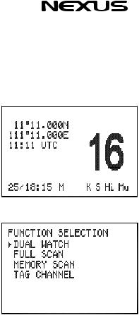
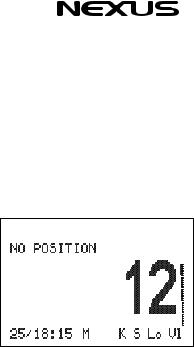
The NX2000 is switched on by pressing the (ON) key once. If a GPS receiver has been connected to the NX2000, the MAIN screen will be as below:
Press the (F) key on the front panel once to enter the Function Selection mode. The FUNCTION SELECTION screen will be displayed as below:
Press the ▲ or ▼ key to move the cursor to the required function (DUAL WATCH, FULL SCAN, MEMORY SCAN, TAG CHANNEL), then press (F) key to confirm. The relevant screen will be displayed. Press (F) key again or press (16) key to restore normal operation, and press (CLR) key to change to the main screen.
5.1DUAL WATCH (DW)
Dual Watch enables the Radio to scan between the selected channel and priority channel (normally CH16). In Dual Watch mode, the DW indicator will appear on the bottom line of the LCD.
Note that the Radio will not transmit, nor will alternative channels be able to be selected while in Dual Watch mode. To restore normal operation press (F) key again or press channel (16) key.
11

English |
VHF NX2000 |
5.2Full Scan (FS)
This function scans through each channel sequentially until a signal is detected above the squelch level set. Once the signal ends or drops below the squelch level, the Radio will continue scanning. Alternatively, you can instruct the NX2000 to continue scanning even if a signal has been detected on any particular channel by pressing the ▲ key once. When in Full Scan mode, FS will appear on the bottom line of LCD.
Note that the Radio will not transmit, nor will alternative channels be able to be selected while in Full Scan mode. To restore normal operation press (F) key or press channel
(16)key.
5.3Memory Scan (MS)
The Memory Scan operates in the same way as the Full Scan, except that it will only scan channels that have been entered into the Scan Memory. If no channels have been entered into the memory then this function will not be available.
When in Memory Scan mode, “MS” will appear on the bottom line of the LCD.
5.4Tag Channel
This function is to tag or cancel tag on a channel, which means select or unselect a channel for Memory Scan. If a channel is tagged then the “M” indicator will appear on the bottom of LCD.
To tag a channel, enter the desired channel number on the Microphone controller and press “F” on the front panel. Select TAG CH and press “F” again. To delete the tag for a channel, repeat the procedure above.
5.5Squelch Control
When the (SQ) key on the front panel is pressed, the squelch level bar and “Sq” symbol will appear at the right side of the screen as below:
12
VHF NX2000 |
English |
Then use ▲ and ▼ key on the front panel to adjust the receiver muting threshold (squelch) level.
To cut out weaker signals, press ▲ key to increase the squelch until the background interference noise disappears. To receive weaker signals press ▼ key to decrease the squelch.
5.6Volume Control (VOL)
Press the (VOL) key on the front panel, the volume control screen will be displayed. The level bar and character “VL” will appear on the right side of the screen as below:
Press ▲ key to increase the volume. Press ▼ key to reduce the volume.
5.7Channel 16 (16)
Pressing the (16) key will automatically select channel 16 on high power. Any active function (DUAL WATCH, DSC SETTING, LOG VIEW etc) will be cancelled.
5.8Channel Selection (▲/▼)
Press ▲ key to go up through the channels. Press ▼ key to go down through the channels.
Channel Selection Shortcut:
Select the desired channel directly from the main screen by pressing the channel number on the fist microphone/controller, and then press “ENT” to confirm.
13

English |
VHF NX2000 |
5.9HIGH / LOW Power Selection (H/L)
Press (H/L) key to select high or low output power of RF. A “Hi” or “Lo” indicator will appear on bottom of LCD.
5.10 Time Out Timer
A time out timer is provided to prevent continuous transmissions for periods greater than 5 minutes. In the event that the radio will be needed to transmit for periods longer than 5 minutes, it will be necessary to release the PTT briefly before the 5 minute timer expires.
WARNING
1)Users can press the PTT once again after 5 minutes to continue the transmission. But the radio should be placed somewhere which nobody can touch it to avoid scalding injury.
2)The life of the radio set will be shortened by long time continuous transmission.
14
 Loading...