

Page 1
0
Installation and Operation Manual
Page 2
1
Introduction
Thank you for choosing Nexus Wind Data instrument. We are convinced that you will
appreciate all the valuable information either you are a cruiser or a racer. It is important
that you are following this instruction regarding installation and operation.
If the instrument are to be used in a Nexus Network, there are some systems settings that
are dependent on where the transducers are installed, i.e. at the instrument or at the
Server.
This manual is written for Nexus Wind Data instrument version 1.00
Edition: June 2000
INTRODUCTION
Page 3

2
1 Part specifications............................................................................................................4
2 Installation........................................................................................................................6
2.1 Installing the instrument........................................................................................... 7
2.2 Installing cable.........................................................................................................8
2.3 Connections in Nexus Network.................................................................................8
2.4 Connection of log transducer....................................................................................9
3 First start (only in a Nexus Network)............................................................................... 10
3.1 Initialising the instrument........................................................................................ 10
3.2 Re-initialising the instrument.................................................................................. 10
4 Operation....................................................................................................................... 11
4.1 About this manual.................................................................................................. 11
4.2 How to use the 4 push-buttons............................................................................... 12
4.2.1 MODE................................................................................................................. 12
4.2.2 DOWN................................................................................................................ 12
4.2.3 UP ...................................................................................................................... 12
4.2.4 KEY.................................................................................................................... 12
4.2.5 Clear................................................................................................................... 13
4.2.6 Calibration .......................................................................................................... 13
4.2.7 Lighting............................................................................................................... 13
4.3 Main function ......................................................................................................... 14
4.4 Analogue function .................................................................................................. 14
4.5 Sub-functions......................................................................................................... 15
4.5.1 Apparent Wind Speed [AWS] .............................................................................. 15
4.5.2 True Wind Speed [TWS] ..................................................................................... 15
4.5.3 True maximum Wind speed................................................................................. 15
4.5.4 Velocity Made Good (VMG)................................................................................. 15
4.5.5 Battery voltage [BAT], option............................................................................... 16
4.5.6 Boat speed [BSP], option..................................................................................... 16
4.5.7 Trip log [TRP], option.......................................................................................... 16
4.5.8 Water temperature [TMP], option......................................................................... 16
4.5.9 Trim function for optimum Wind angle or speed, option....................................... 16
4.6 More Wind Data functions Nexus Network.............................................................. 18
4.6.1 Geographic Wind direction (TWD)....................................................................... 19
4.6.2 WCV, Waypoint Closing Velocity......................................................................... 19
4.6.3 X-track error, XTE............................................................................................... 19
4.6.4 HDC / NXT, Course after tack or jibe................................................................... 21
4.6.5 BTW / NXT, Bearing and angle deviation relative next course.............................. 22
5 Calibration...................................................................................................................... 24
5.1 C10 User settings................................................................................................... 24
5.1.1 C11 Select the dampening................................................................................... 24
5.1.2 C12 Select main information ............................................................................... 24
5.1.3 C13 Displaying boat speed, trip log and temperature, option................................ 25
5.1.4 C14 Display NAV functions, option...................................................................... 25
5.1.5 C15 Beep when key is pressed............................................................................ 25
5.2 C20 Calibration of Log ........................................................................................... 25
5.2.1 C21 Select unit for speed .................................................................................... 25
5.2.2 C22 Calibration of log transducer ........................................................................ 25
5.2.3 C23 Unit for temperature..................................................................................... 26
5.2.4 C24 Temperature offset....................................................................................... 26
5.3 C30 Compass Settings........................................................................................... 26
CONTENTS
Page 4

3
5.3.1 C31 True or magnetic course .............................................................................. 26
5.3.2 C32 Magnetic deviation....................................................................................... 26
5.3.3 C33 Reference for Compass, static or GPS......................................................... 26
5.4 C50 Wind Settings................................................................................................. 27
5.4.1 C51 Network setting of true or apparent Wind angle............................................ 27
5.4.2 C52 Unit for Wind speed..................................................................................... 27
5.4.3 C53 Wind speed calibration................................................................................. 27
5.4.4 C54 Adjustment of Wind angle............................................................................ 27
5.4.5 C55-C62 Calibration table for the Wind transducer.............................................. 27
5.4.6 C63 Speed reference, water or GPS.................................................................... 28
5.4.7 C64 Wind trim reference ..................................................................................... 28
5.4.8 C68 Roll adjustment............................................................................................ 28
5.4.9 C69 Pitch adjustment.......................................................................................... 28
5.5 C70 Configure Nexus............................................................................................. 28
5.5.1 C71 Wind-master................................................................................................ 29
5.5.2 C72 Log-master.................................................................................................. 29
5.5.3 C73 Function on terminal In3 .............................................................................. 29
5.5.4 Connection of trim button.................................................................................... 29
5.5.5 C74 Demo mode................................................................................................. 30
6 Maintenance and fault finding......................................................................................... 31
6.1 Maintenance .......................................................................................................... 31
6.2 Fault finding........................................................................................................... 31
6.2.1 General............................................................................................................... 31
6.2.2 Fault - action....................................................................................................... 32
6.2.3 Error messages................................................................................................... 32
7 Specifications................................................................................................................. 33
7.1 Technical specifications ......................................................................................... 33
7.2 Nexus data bus introduction and user policy........................................................... 33
8 Optional Accessories...................................................................................................... 35
9 Abbreviations ................................................................................................................. 37
10 Warranty................................................................................................................. 36
CONTENTS
Page 5

4
1 Part specifications
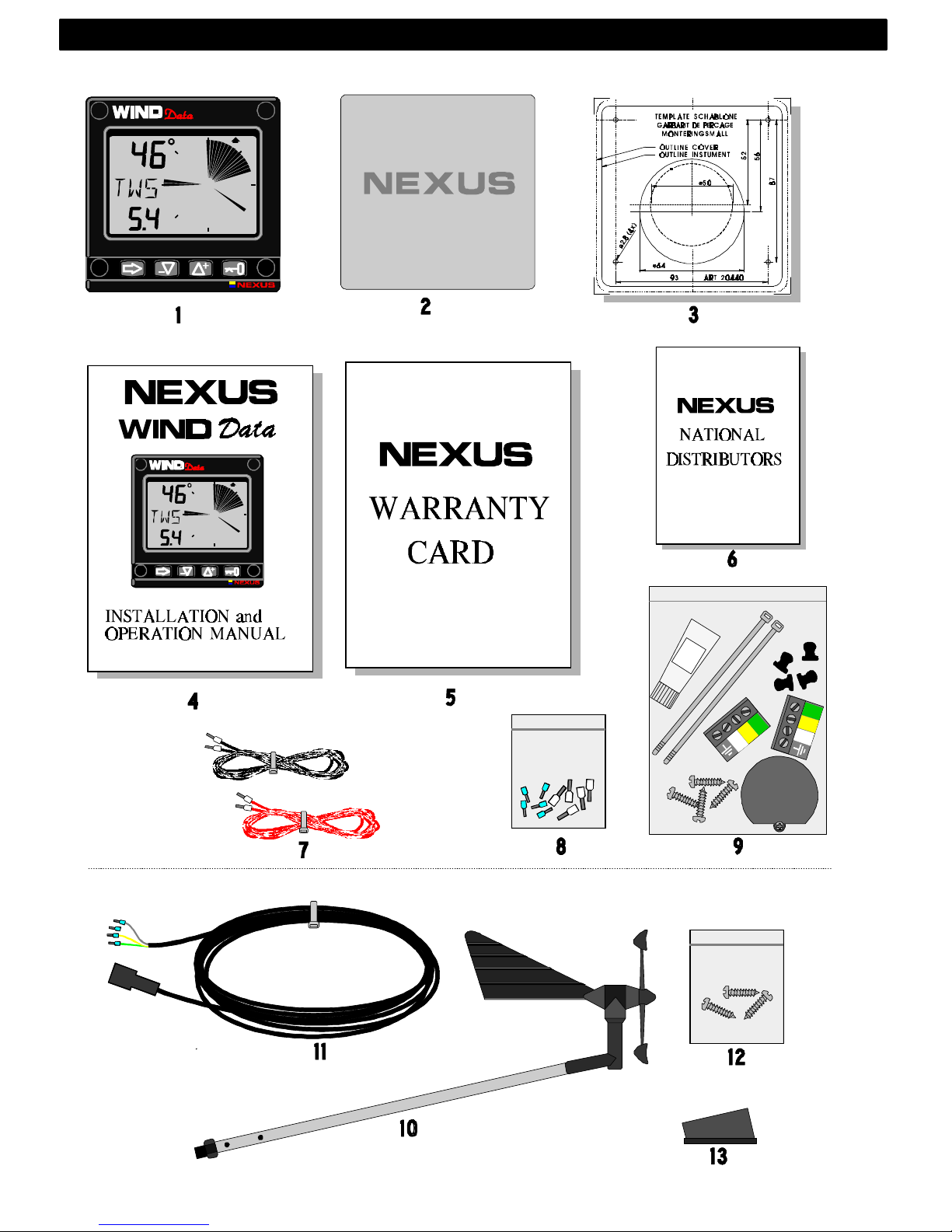
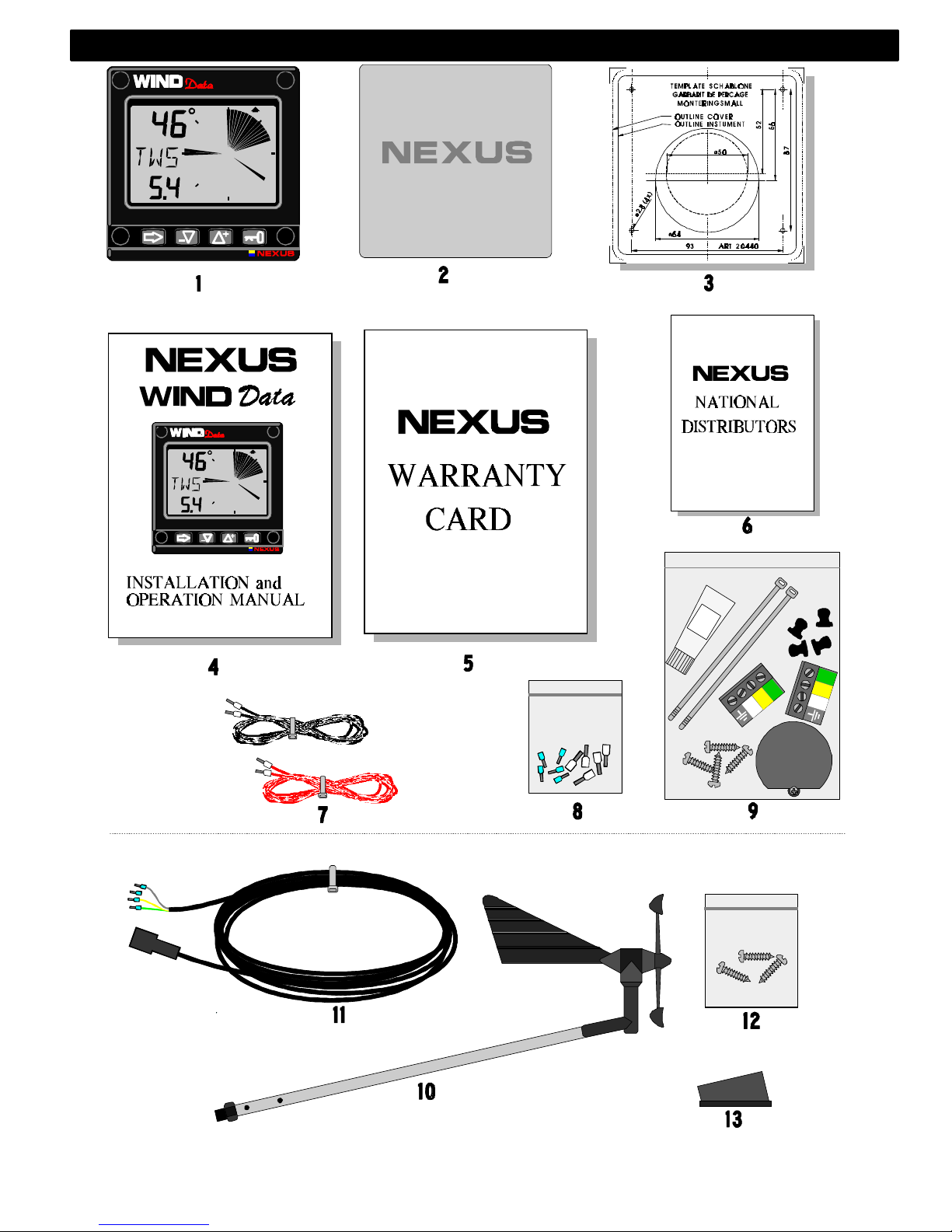
Nexus Wind Data is delivered with all parts for mounting. Check prior to
installation.
Wind Data instrument
Qty. Description Reference
1 Instrument, Nexus Wind Data 1
1 Instrument front cover 2
1 Drill template 3
1 Installation and user manual 4
1 Warranty card 5
1 National distributors list 6
1 Power cable, red and black, 3 m (9 ft) 7
5 Extra wire protectors, 0,25 mm (1/100”) 8
5 Extra wire protectors, 0,75 mm (1/32”) 8
4 Mounting screws for the instrument 9
4 Round rubber covers 9
1 Tube of silicon grease 9
1 Connection cover 9
2 4-pol screw terminal 9
Additional in Wind Data complete with transducer
1 Wind transducer Nexus 10
1 Mast top cable. 25m (83 ft) 11
3 Mounting screws for mast bracket 12
1 Mast head bracket 13
Registering of this product
Once you have checked that you have all the listed parts, please take
time to fill in the warranty document and return it to your national
distributor.
By returning this document, it will assist your distributor to give you
prompt and expert attention, in the event of your experiencing difficulties
with this product. Keep your proof of purchase. Also, your details are
added to our customer database so that you automatically receive new
product catalogues as and when they are released.
PART SPECIFICATIONS
Page 6
5
PART SPCIFICATIONS
Page 7
6
1 Installation
You can install the Nexus Wind Data in three different ways:
• The wind transducer is connected directly to the Nexus Wind Data
instrument
• By using the connection kit when both log and wind transducers are
installed with a single Wind Data.
• The installation may also include a Nexus Server where all transducers
may be connected. All data including power will pass along one cable.
• The installation includes 6 major steps:
1. Read the installation and operation manual.
2. Plan where to install the transducers and instruments.
3. Run the cables.
4. Install the transducers and instruments.
5. Take a break and admire your installation.
6. Learn the functions and calibrate your system.
Before you begin drilling ... think about how you can make the installation
as neat and simple as your boat will allow. Plan where to position the
transducers, Server and instruments. Think about leaving space for
additional instruments in the future.
• A few ”do nots” you should consider:
− Do not cut the cables too short. Allow extra cable length at the Server so
it can be disconnected for inspection without having to disconnect all
attached cables.
− Do not place sealant behind the display. The instrument gasket
eliminates the need for sealant.
− Do not run cables in the bilge, where water can appear.
− Do not run cables close to fluorescent light sources, engine or radio
transmitting equipment to avoid electrical disturbances.
− Do not rush, take your time. A neat installation is easy to do.
• The following material is needed:
Wire cutters and strippers.
Small and large Philips and small flat head screw driver.
Hole saw for the instrument clearance hole 63 mm (2½").
2.8 mm (7/64") drill for the mounting holes in wood.
3.2 mm (1/8") drill for the mounting holes in fibre glass.
Plastic cable ties
If you are doubtful about the installation, obtain the services of an
experienced technician.
The warranty is not valid if you have damaged the instrument by
drilling through the front mounting holes.
2: INSTALLATION
Page 8
7
1.1 Installing the instrument
• Place the adhesive drill template on the desired location for the
instrument. Drill the 4 screw holes using a 2.8 mm (7/64") drill for wood or
3.2 mm (1/8") for fibre glass. Use a 63 mm (2½") hole saw to machine the
clearance hole for the instrument connection socket. Remove the
template.
Note: Never drill through the instruments 4 mounting holes as the
gaskets may be damaged and thus cause leakage. The warranty is
not valid for damage caused by drilling through the mounting holes.
• Run the Nexus Network cable from the Server to the instrument.
• Cut the Nexus Network cable to length. Peel off about 35 mm (1,4") of the
cable insulation. Remove about 6 mm (1/4") from the 3 isolated wires
(the 4th wire is an earth / screen). Attach the 4 cable protectors to the
wires using a pair of flat pliers.
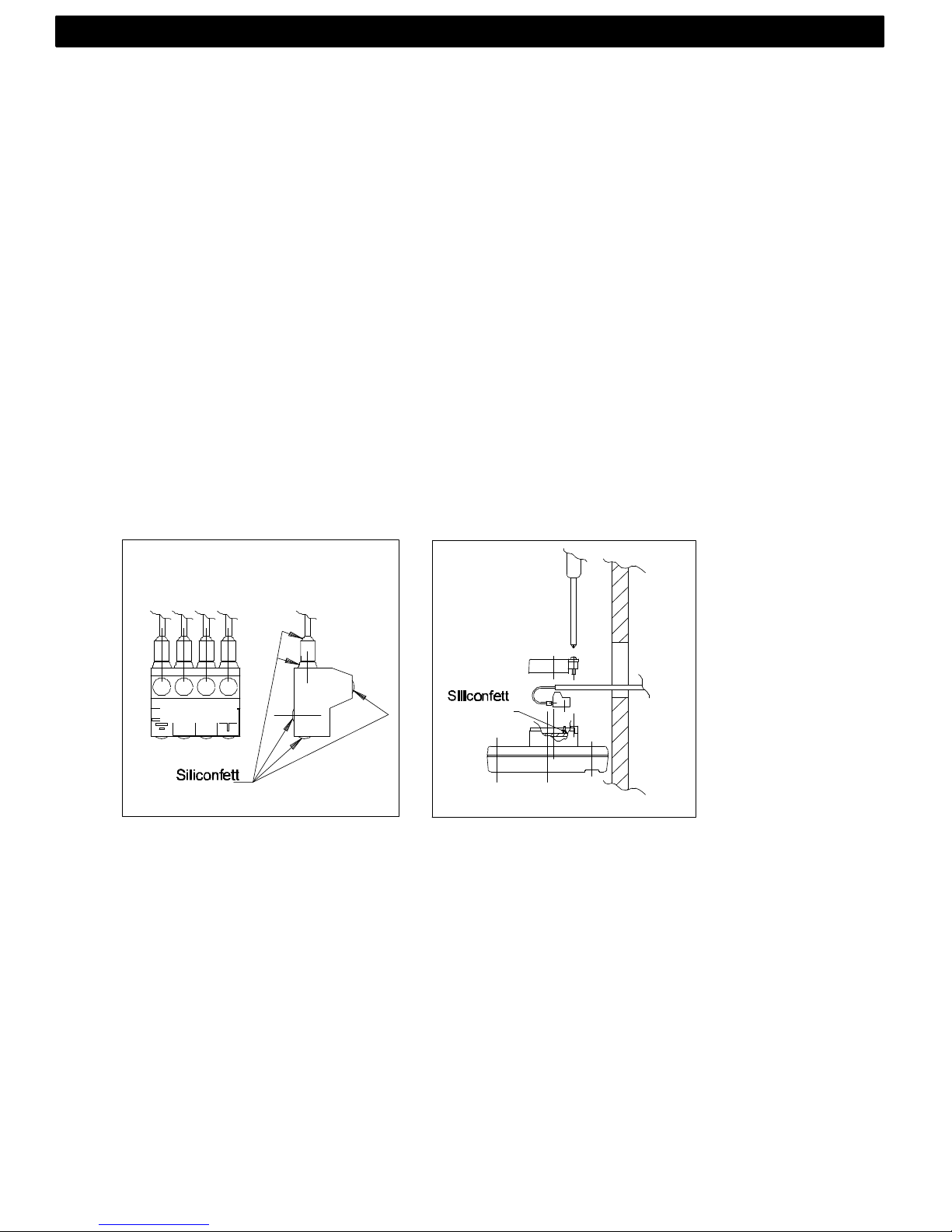
• Connect the 4 cable protectors to the 4-pole jack plug as shown. Apply
silicon paste on all locations as shown.
Note: Must be done to avoid corrosion.
• Apply silicon paste to the instrument connection pins at the back of the
instrument. Press the jack plug onto the instrument pins. Press down the
cable in the cable leads. Mount the connection back cover with the screw.
• Mount the instrument in the pre-drilled position.
Note! Use all 4 screws, and tighten the screws (in cross pattern) so
the gasket will be evenly compressed to 1/3 of its original thickness.
Very important for a correct sealing to avoid leakage!
• Press on the 4 rubber caps to seal and hide the mounting screws.
Your instrument installation is done!
Silicon paste
Silicon paste
2: INSTALLATION
Page 9
8
1.2 Installing cable
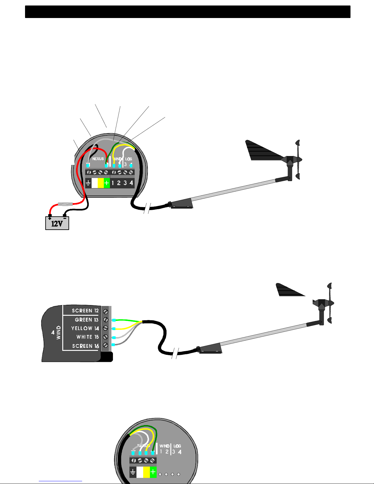
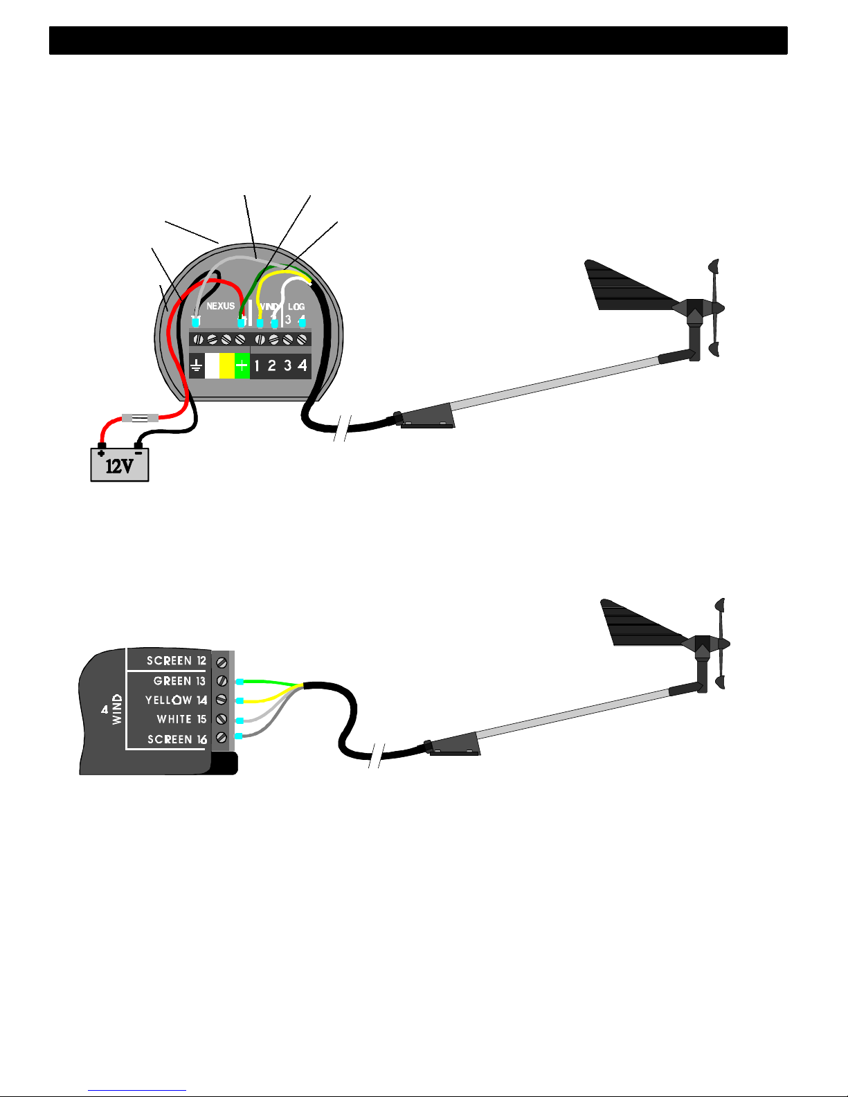
The power cable is connected via a 3A fuse from the battery or at the
boats fuse panel and direct to the instrument or Server. One red and one
black power wire is included. Note, set C71 On (see 5.5.1)
Always connect a 3 AMP fuse between Power supply and
instrument.
1.3 Connections in Nexus Network
If you already have a Nexus Network i.e. a Server, it is more practical to
connect the transducer to the Server due to the single instrument cable
installation. Note, set C71 OFF (see 5.5.1)
The instrument is then connected to the Server’s Nexus Network terminal
(pin 5, 6, 7 and 8) or any instrument .
Server
Transducer
3A Fuse
Black
Screen
Red
Green Yellow
White
2: INSTALLATION
Page 10
9
1.4 Connection of log transducer
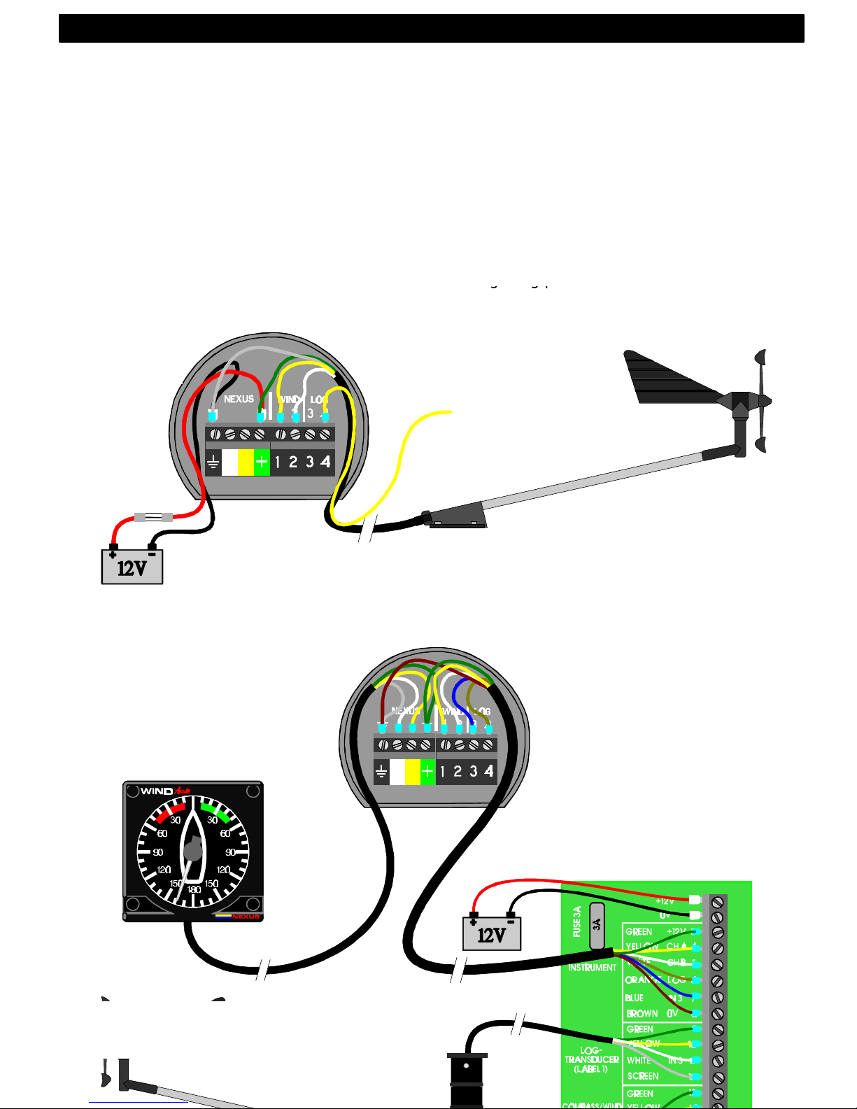
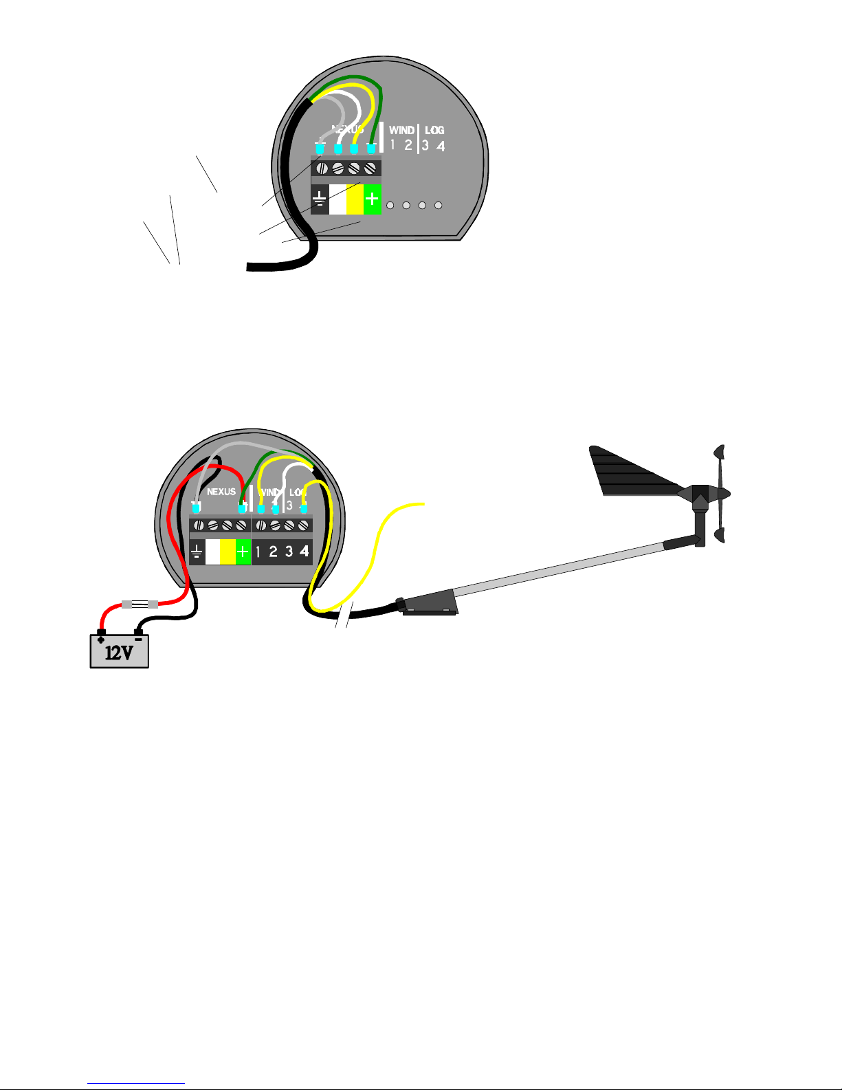
If you have an other log instrument i.e. a Nexus log, a Star log, a D-20
log, a 2200 log or a 220 log, you may connect the single log pulse wire
from that instrument to the Wind Data instrument terminal 4.
If you don’t have a log instrument, but want to install a log transducer,
use the connection box (Art. no: 21453 ).
From log transducer,
NEXUS, Star, D-20,
2200 or 220
3A Fuse
2: INSTALLATION
From Server or other
NEXUS instrument
Page 11

10
2 First start (only in a Nexus Network)
2.1 Initialising the instrument
At power on, the instrument will perform a self test. The display will first
show all segments, then the software version number and the Nexus
Network ID number.
At first power on after installation, you will be asked to press KEY
[PrSKEY]. This will give the instrument a logical ID number on the Nexus
Network.
To initialise the instrument, press KEY on all installed digital instruments,
one at the time.
Note: Always wait for the text ”Init OK”
to be displayed, before you press KEY
on the next instrument!
The Server automatically gives the first unit ID number 16, then 17 and
so on. The order in which you press KEY is the same order as the
instruments will be given a logical ID number on the Nexus Network.
The example shows that the instrument version number is 1.00 and the
given logical ID number is 16.
2.2 Re-initialising the instrument
If two instruments by mistake have the same ID number, this can cause
disturbance and block the information on the Nexus data bus.
To re-initialise the instrument, press DOWN and UP together during the
power up sequence when version and ID numbers are displayed.
The display self test is then re-started on all instruments and you will be
asked to press KEY on each instrument as explained above.
Note! If you do not succeed to re-initialise, we suggest you disconnect all
but one instrument with the same ID number, then repeat the above
procedure.
3: FIRST START
Page 12

11
3 Operation
3.1 About this manual
• Each time a push-button are referred to in this manual, the push-button
name will appear in bold and CAPITAL letters, e.g. MODE.
• Unless otherwise stated, the push-button presses are momentary.
• Each time a function is mentioned in the text, it will be in brackets and in
the same format, where possible, as displayed, e.g. [AWA].
• This manual has been written to be: Compatible with Wind Data
instrument from software version 1.0.
• All functions followed by the text option is not valid in a factory set-up
instrument. See calibration to be able to display these functions.
Note!
We have put down a lot of effort in order to make this manual correct and
complete. But since we continuously make our products better, some
information can differ from the products functions. If you need further
information contact your national distributor
4: OPERATION
Page 13

12
3.2 How to use the 4 push-buttons
3.2.1 MODE
A press on MODE change the mode of the graphical display. It scrolls in
a circular pattern, one step for every press.
The MODE button is also used to move the cursor when in edit mode. A
press on MODE moves the cursor in a circular pattern, one step to the
right for every press.
A press on MODE and DOWN together, back steps cursor to the
preceding step.
When in editing mode a long press (>2sec) on MODE will escape from
that editing mode.
3.2.2 DOWN
A press on DOWN moves to the next sub-function.
In edit mode it decreases to previous digit.
3.2.3 UP
A press on UP moves to the previous sub-function.
In edit mode it increases to next digit.
3.2.4 KEY
A press on KEY unlocks a digit to access edit mode.
When unlocked, the digits are ”active” (flashes) and can be edited by
pressing DOWN, UP and MODE as required.
When finished editing, lock the digit by another press on KEY.
4: OPERATION
MODE
DOWN
UP
KEY
APPARENT
WIND ANGLE
TRUE
WIND ANGLE
TRIM
FUNCTION
MAIN
FUNCTION
INFOTEXT
SUB-
FUNCTION
Page 14

13
3.2.5 Clear
A press on DOWN and UP together, clear digits.
3.2.6 Calibration
To access calibration mode, press and hold KEY more than 2 seconds.
To return to main function mode, press KEY when the text return [RET] is
shown.
3.2.7 Lighting
The instrument uses red back lighting for the display and the 4 pushbuttons. The lighting can be set at 4 different levels.
To access the light control, press and hold MODE for more than 2
seconds. The flashing text [Lit OFF] will be displayed and the display will
be lit momentarily.
To select between the 4 light levels, press UP: [LOW], [MID], [MAX] and
[OFF]. To lock the selected level, press KEY.
The selected light level will be copied to all Nexus instruments connected
to the system. When the lighting is on, it is not possible to reduce or turn
off the lighting on an individual instrument.
4: OPERATION
Page 15

14
3.3 Main function
Top data is relative Wind angle, [AWA] (Apparent Wind Angle). As an
alternative to [AWA] the following can be displayed:
[AWS] (Apparent Wind Speed).
[TWA] (True Wind Angle) if the log transducer is connected.
[TWS] (True Wind Speed) if the log transducer is connected.
To change between these functions, see C12, 5.1.2.
3.4 Analogue function
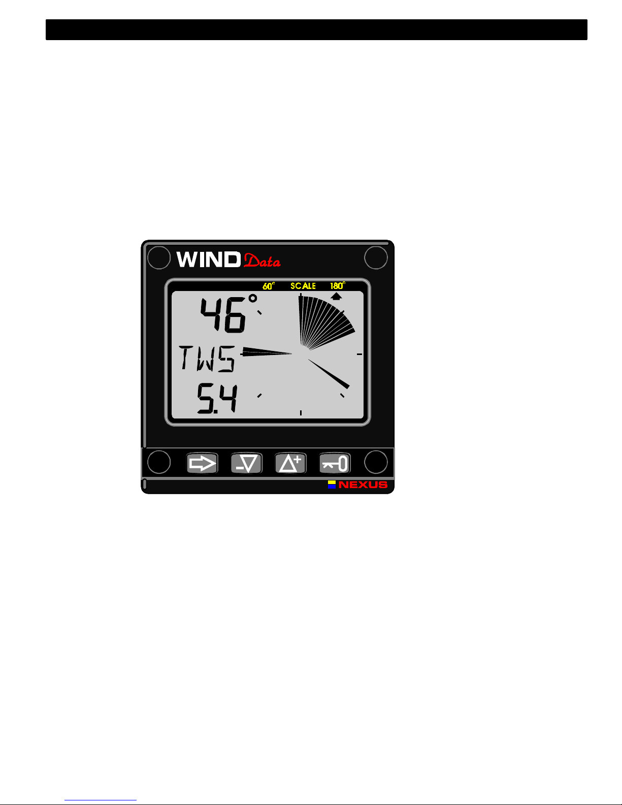
Change Wind scale between 180°° and 60°° with MODE . Selected scale
is shown with the LCD arrow pointing at scale.
The text [APP] displays selected main function as apparent Wind angle
or Wind speed.
MIX 180°° The text MIX 180° means that both APP and TRUE Wind
angle is displayed in scale 180°.
MIX 60°° The text MIX 60° means that both APP and TRUE is
displayed in scale 60.
The scale can be altered between 60° and 180° to get more accurate
readings. At scale 180° each sector represent 5° and at scale 60° each
sector represent 1 2/3°. See the example below .
4: OPERATION
WIND
Page 16

15
3.5 Sub-functions
Select sub-function with UP or DOWN.
Information text for the sub-function is displayed. You may also ”park”
your favourite function so it will automatically be displayed after power
on.
Press both MODE and KEY to ”park” the displayed function. The display
will flash once to confirm that you have ”parked” the function.
3.5.1 Apparent Wind Speed [AWS]
The text [AWS] (Apparent Wind Speed) and its value is displayed below.
The text [AWS] is toggled with the text [KTS] (KnoTS), [M/S] (Metres/S)
or [BF] (Beaufort).
3.5.2 True Wind Speed [TWS]
The text [TWS] (True Wind Speed) and its value is displayed below.
The text [TWS] (True Wind Speed) is toggled with the text [KTS]
(KnoTS), [M/S] (Metres/s) or [BF] (BeauFort).
3.5.3 True maximum Wind speed
Press the KEY in the sub-function: [TWS] to display maximum true Wind
speed. After 5 seconds the display will go back to [TWS] again.
Re-set or clear the [MAX] Wind speed value by pressing UP and DOWN
together or switch off the power.
3.5.4 Velocity Made Good (VMG)
The text [VMG] (Velocity Made Good) is
displayed with the actual boat speed towards or
against the Wind.
The water speed information from the log
transducer is needed. The speed information
can be taken from the log transducer or from
Nexus Network. VMG = 0.0 knots when the true
Wind angle is perpendicular to the boat.
4: OPERATION
WIND
Page 17

16
3.5.5 Battery voltage [BAT], option
The text [BAT] will display battery voltage. The voltage is measured
inside the instrument and will not compensate for any voltage drop
caused by installation.
3.5.6 Boat speed [BSP], option
The text [BSP] will display boat speed (water speed). The text [BSP] will
toggle with selected unit, i.e. (KTS), (KMH) or (MPH).
As an option, you may add or remove displaying boat speed [BSP],
trip log [TRP] and water temperature [TMP]. See further under
calibration.
3.5.7 Trip log [TRP], option
The text [TRP] is displayed and will show trip distance from 0.00 to 99.9
nautical miles, kilometre or miles. After 99.9, 0.00 is displayed. Clear trip
by pressing UP and DOWN together.
3.5.8 Water temperature [TMP], option
The text [TMP] is displayed with water temperature in Celsius or
Fahrenheit.
This function require a Nexus or Star log transducer.
3.5.9 Trim function for optimum Wind angle or speed, option
The text [TRM] and [OFF] is displayed when this function is off. The trim
function can be used as an aid to keep the correct tacking angle or to
discover speed changes caused by sail or rig trimming. Some of the
functions can only be used when the Wind Data is connected to Nexus
Network.
As the first example we will use [TRM AWA] (TRiM Apparent Wind
Angle).
To trim on Wind angle deviation, select the text:
Press UP and DOWN together, the display will flash. Select [AWA] with
DOWN and confirm with KEY.
4: OPERATION
Page 18

17
Select the level of dampening [d0-d9] and confirm with the KEY.
The default (or latest used) Wind angle is displayed. You may accept the
proposed angle by pressing the KEY or enter a new Wind angle with UP,
DOWN and MODE before confirming with KEY.
The entered Wind angle will be lost when power off. You may however
select a default Wind angle in set-up. See C64 5.4.7.
Every time you select this function, or after power up, the pre-set value is
proposed.
On the display you will see the text TRM and AWA toggling together with
your Wind angle. On the graphic part you will see your reference angle as
one straight horizontal segment when actual angle is equal to the pre-set
angle. At the same time you will see apparent and true Wind angle.
The deviation is displayed visible upwards or downwards from the
horizontal line to +/-15°. The maximum visible deviation is 15°. When the
deviation is between 15° and 30° the 15° sector is lit. When larger then
30° the segment sector is blanked out.
Trim on speed:
Select the trim function.
Press UP and DOWN together. Select text (BSP) by pressing UP and
confirm with KEY.
There is a number of different ”speeds” to be used for trimming. The
most common is [BSP] (Boat SpeeD) and [VMG] (Velocity Made Good).
The Wind Data instrument can also display deviation from optimum
calculated boat speed [TBS] or (Target Boat Speed).
The TBS is normally calculated by use of polar diagram on PC with
racing software. The value ”Target Boat Speed” is transmitted through
the Nexus Server on the NMEA 0183 input. The Server will then transmit
TBS on the Nexus Network.
On the Wind Data display you will see both the digital value in % and the
graphical value as a 2% variation for each segment.
You may select ”speeds” to TRIM, from this list:
BSP Boat speed Log transducer!
AWS Apparent Wind Speed
TWS True Wind Speed Log transducer!
SOG Speed Over Ground Navigator!
4: OPERATION
Each sector represents 2°
Page 19

18
DRF Drift Log transducer + Compass +
Navigator!
WCV Speed towards a waypoint Navigator!
VMG Velocity Made Good Log transducer!
TBS Optimum speed based on polar diagram PC + NMEA 0183 through
Nexus Server!
OFF Function is OFF
When [BSP] (or other function) is selected, the dampening [d3] is
flashing. Select dampening level and confirm with KEY.
The text [% OFF] is then displayed to show that the function is selected,
but no reference is yet set.
Press KEY to set [BSP] reference.
The display will now show you the text [%] toggling with text [BSP] or
whatever trim you have selected.
The speed variation is expressed in % from set value.
Press the KEY every time you wish to set a new trim reference value.
There is an option to use an external trim button to set a new trim
reference. See more in the calibration.
3.6 More Wind Data functions Nexus Network
By adding (or using) the Wind Data instrument in the Nexus Network,
more functions will be added if the corresponding transducer is
connected.
The Wind Data functions may be added or removed by the user.
The Wind Data instrument can be used in a small Network together with
the Multi, Log or analogue instrument, without a Server.
In order to make the installation easy when using both log and Wind
transducer in a small Network we recommend you to install with
connection kit art.no. 21453. Only one cable will carry the signals to the
instrument, then there is one Network/power cable to the Multi or Log
instrument. (See 2.1.4).
When using the Wind Data in a bigger Network with more then 3
transducers, we recommend you to use the Nexus Server.
Only one cable will be used to connect all instruments. You will also have
the NMEA 0183 input/output.
If you need to be able to read the depth information on more then one
instrument, the Server is the only choice.
Network bonus function:
Each sector represents 2%
4: OPERATION
Page 20
19
If you are using the race timer on the Multi or Log instrument you will
have a graphical 60 second countdown timer ”popping up” on this
instrument.
In this example there is 45 second to start.
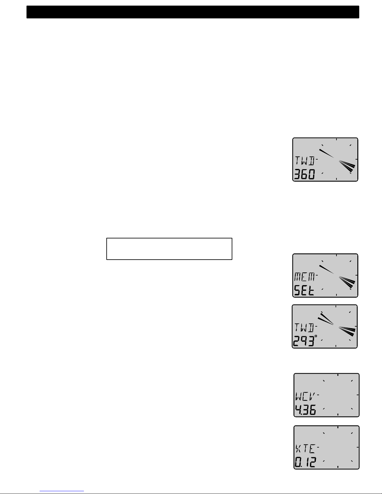
3.6.1 Geographic Wind direction (TWD)
To get this function, set NAV = On C14 (See 5.1.4).
Text [TWD] is displayed shortly, then is the abbreviation for Wind
directions displayed, [SSW], [NO], [WNW] etc. together with the
numerical direction below. The graphic direction is also displayed by
pressing MODE one or more times until the display to the right is
displayed together with the ”pointer”.If the Compass transducer is
missing but there is a GPS installed, you may use the GPS as a
reference for heading under the criteria that the vessel must be moving.
Change C33 from USE Hdc to USE COG.
(See 5.3.3)
When the boat is laying still, the TWD will be random readings if
COG is used.
You may also check long term geographical Wind shifts by entering
a ”marker” at present Wind direction as a remainder.
The ”marker” will stay until power off or by clearing the function.
A Wind shift of 5° will be easy to detect after hours of sailing.
Select function [TWD 360°] with MODE, and when the text [TWD] is
flashing press KEY.
The ”marker” is now set. When there is a constant Wind shift, you will
see this ”marker” as a slow blinking reminder of the origin Wind direction.
3.6.2 WCV, Waypoint Closing Velocity
To get this function, set NAV = On C14 (See 5.1.4).
The text [WCV] is displayed with the actual speed towards your Waypoint
if a Waypoint is selected in your GPS navigator.
3.6.3 X-track error, XTE
To get this function, set NAV = On C14 (See 5.1.4).
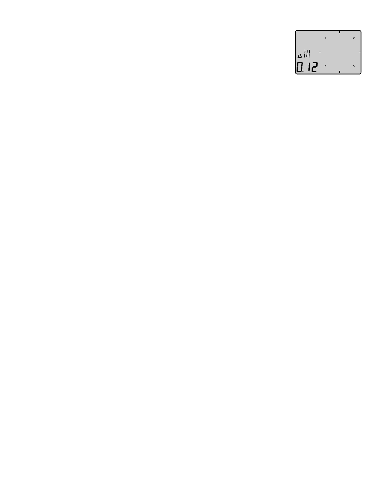
The text [XTE] is displayed shortly when this function is selected, then a
symbolic ”boat” is displayed on one side of the ”road” which is displayed
as three vertical lines.
Each sector represents 5°
4: OPERATION
Page 21
20
Your ”boat” will be displayed on the right or left side of the road. The
distance is also displayed and can be in either Nautical mile, Km or
Miles.
Page 22
21
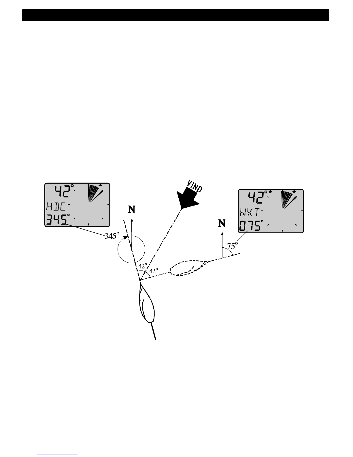
3.6.4 HDC / NXT, Course after tack or jibe
To get this function, set NAV = On C14 (See 5.1.4).
This function also needs a Compass connected to the Nexus Server
If the Compass sensor is missing, the HDC may be replaced by the COG
(Course over ground) by setting the reference in COG. (See C33 5.3.3).
The text [HDC] is displayed with actual magnetic or true heading. After
4secs. the text [NXT] together with the true or magnetic course to keep
after tack or jibe.
Note! The boat’s drift must be included in your decision when to tack, to
reach the mark.
After a tack, it will take some minute before the new tack angle is steady
due to the dampening.
The functions [HDC] and [NXT] is toggling, but they can be locked or
unlocked by use of the KEY.
4: OPERATION
Page 23
22
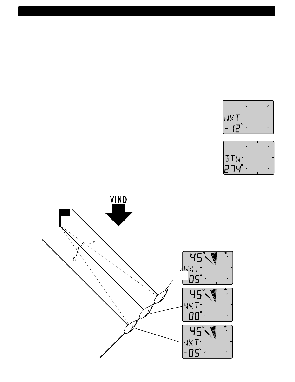
3.6.5 BTW / NXT, Bearing and angle deviation relative next course
To get this function, set NAV = On C14 (See 5.1.4).
This function is using both the Compass and the navigator information to
calculate the angle deviation between the bearing and the course after
tack. i.e. the angle deviation is exactly what you should expect after the
tack.
[BTW] is showing the actual Bering to Waypoint and [NXT] is showing
the negative [-], positive tack or downWind angle that you would expect if
you where tacking or jibing.
You may use COG but our recommendation is to use the Compass since
the response and accuracy is superior. If you use COG without a
differential GPS you will loose too much accuracy in the information.
[BTW] and [NXT] is toggling.
TACK :
Example: If you expect your drift to be 05°, your tack should be made
when you read [NXT 05°] to be on (and stay on) lay line.
While you are approaching the proper angle, the value is negative, i.e. 12° and then increasing to 00° which is on lay line after tack except for
the drift which is the margin you must add to compensate for the drift.
Note! This function is only used on the last leg.
WIND
4: OPERATION
Page 24
23
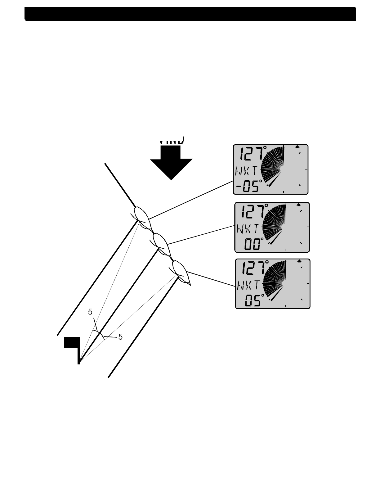
DOWN Wind:
When sailing downWind, the boat can always be sailing at the highest
WCV (speed towards the mark). When [NXT] is [00°] you should jibe
because your drift is not important.
The functions [BTW] and [NXT] is toggling, but can be locked or unlocked
by use of the KEY.
Note! This function is only used on the last leg.
4: OPERATION
WIND
4: OPERATION
Page 25

24
4 Calibration
To get the most out of your Nexus instrument, it is important to carefully
calibrate the instrument. The calibration values are stored in a non
volatile memory.
To access calibration mode, press and hold KEY more than 2 seconds.
To select a calibration code, press DOWN, UP and MODE as required.
To return to normal operation mode, press KEY when the text return
(RET) is displayed.
The different calibration routines are divided into five groups:
C10 - C15 = USR, User settings.
C20 - C24 = BSP, Log transducer and temp calibrations.
C30 - C33 = HDC, Compass settings.
C50 - C64 = WND, Wind transducer settings/calibrations.
C70 - C74 = CON, Configuration of the Nexus system.
To change a calibration value, press KEY.
To select calibration value, press DOWN, UP and MODE as required.
To lock the selected value, press KEY.
4.1 C10 User settings
To return to normal mode, press KEY when the text [rET] is displayed.
4.1.1 C11 Select the dampening
The dampening will affect Wind angle, Wind speed, boat speed and
VMG. Dampening is between d0 (0s) and d9 (1’20).
To change the dampening, press KEY and change with UP or DOWN
and enter with KEY.
4.1.2 C12 Select main information
Select function to be display at the top left of the LCD display. There is
five options.
AWA Apparent Wind Angle.
TWA True Wind angle by the use of log transducer.
AWS Apparent Wind speed.
TWS True Wind speed by use of log transducer.
WIA Main setting for the Nexus system. When selected, all
instruments using WIA will be system affected and following
the set-up in the Multi Control setting C51.
5: CALBRATION
Page 26

25
4.1.3 C13 Displaying boat speed, trip log and temperature, option
When set to OFF, the functions will be removed from the display. The
Wind Data instrument may be used as a Server in the Nexus Network,
transmitting the log and temp to other Nexus instruments without having
the information displayed in this instrument.
4.1.4 C14 Display NAV functions, option
NAV functions are only useful when the Wind Data is connected in a
Nexus Network with Compass transducer and a navigator. The selection
NAV On will add the functions as described under Nexus Network See
4.6.
4.1.5 C15 Beep when key is pressed
Setting On will make a beep at every key press, while OFF is silent.
4.2 C20 Calibration of Log
To return to normal mode, press KEY when the text [rET] is displayed.
4.2.1 C21 Select unit for speed
Unit for speed, knots (KTS), km/h (K/h) or miles/h (m/h).
4.2.2 C22 Calibration of log transducer
Calibration value for speed and distance (1.00 - 1.99).
Drive the boat a measured distance at normal speed.
Compare the distance with the trip counter.
Calculate the value with the following formula.
True distance from the sea chart: T
Log trip counter distance: L
The current calibration value: C
New calibration value: N
If you suspect a current in the water, drive the boat in both directions and
divide trip counter distance by two.
If the Wind Data is installed with Nexus Server where the log is
already calibrated, no further calibration is needed.
5: CALBRATION
Page 27
26
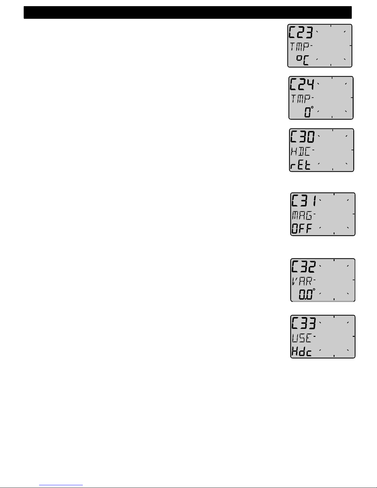
4.2.3 C23 Unit for temperature
Select degree Celsius [C] or degree Fahrenheit [F].
4.2.4 C24 Temperature offset
By adding a positive or [-] negative value here, it will be added as an
offset before displayed as the temperature.
4.3 C30 Compass Settings
To return to normal mode, press KEY when the text [rET] is displayed.
4.3.1 C31 True or magnetic course
This function is only used when the instrument is connected in the Nexus
Network. [MAG On] will display bearing, course and Wind direction as
magnetic. The LCD indication is (MAG). Select [OFF] to display all as
true.
4.3.2 C32 Magnetic deviation
Set the deviation direction first, i.e. [+E] (East) or [W] (West), then enter
the magnetic value in 1/10 of a degree.
4.3.3 C33 Reference for Compass, static or GPS
Select heading Compass [Hdc] when the Compass transducer is
connected to the Nexus Network (recommended).
Select course over ground [COG] when a GPS navigator is connected,
but no Compass.
Select STA for static use at fixed installations, such as at the yacht club,
airfield, ferry berth and so on.
In static mode you may mount the transducer in the direction of North, or
if not possible, you may adjust the transducer electronically. See C54,
5.4.4.
Note! [COG] as reference will only operate properly when the boat is
doing speed over ground.
5: CALBRATION
Page 28

27
4.4 C50 Wind Settings
To return to normal mode, press KEY when the text [rET] is displayed.
4.4.1 C51 Network setting of true or apparent Wind angle
Select true [TWA] or apparent Wind angle [AWA] as main function. The
optional analogue Wind instrument will display the same selection. All
Multi Control instruments which have the calibration code 63 set to [WIA]
will display what is selected in C51.
4.4.2 C52 Unit for Wind speed
Unit for Wind speed [KTS] for (KnoTS), [M/S] for (Metres/S) and [BF] for
(Beaufort).
4.4.3 C53 Wind speed calibration
Do not change this factory setting.
4.4.4 C54 Adjustment of Wind angle
Mast top unit misalignment adjust value or the so called ”A-fault”, makes
it possible to adjust any horizontal angle.
Example: If the Wind angle is +4° when you sail/drive the boat straight
into the Wind, set the calibration value in C54 to 356°.
4.4.5 C55-C62 Calibration table for the Wind
transducer
In channels C55 to C62 you set the calibration values for the mast top
unit. Each mast top unit is individually calibrated for best accuracy. See
the separate Wind calibration certificate supplied with each mast top unit.
Each of the inter-cardinal directions are calibrated.
C55 000 000°
C56 045 045°
C57 090 090° Set the calibration value according
C58 135 135° to the provided calibration certificate
5: CALBRATION
Page 29
28
C59 180 180°
C60 225 225°
C61 270 270°
C62 315 315°
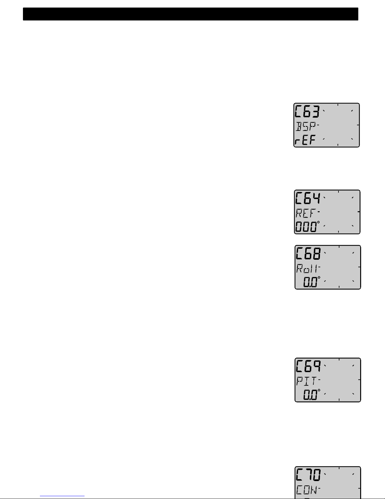
4.4.6 C63 Speed reference, water or GPS
This function is only used when the instrument is connected in the Nexus
Network. When [BSP] is selected, the reference is water speed provided
by the log transducer for calculation of true Wind speed and angle, VMG
and NXT function together with the BTW.
When [SOG] is selected, the reference is speed over ground.
Note! the boat must be moving to give correct readings. We also
recommend you to use differential GPS to get good readings.
4.4.7 C64 Wind trim reference
This default reference for Wind angle trim. Each time the instrument is
powered up and apparent Wind angle is selected as trim reference this
value will be pre-set.
4.4.8 C68 Roll adjustment
This adjustment is valid only if roll is selected in C73 (you have to exit
and enter the calibration again after C73 is set to Roll.)
Adjustment of the roll offset. Mount the roll transducer according to the
instructions. Adjust the offset so the roll is displaying 00° when the boat
is horizontal. By entering a minus sign [-] in front of the value the roll will
be decreased by the value. When the offset is without a minus sign, it will
be added. When a roll transducer is connected the Wind- speed and
angle will be compensated for roll and accuracy is increased.
The roll sensor is not yet available (at the time for this manual).
4.4.9 C69 Pitch adjustment
This adjustment is valid only if roll is selected in C73 (you have to exit
and enter the calibration again after C73 is set to Roll).
Adjustment of the pitch offset. Mount the pitch transducer according to
the instructions. Adjust the offset so the pitch is displaying 00° when the
boat is horizontal. By entering a minus sign [-] in front of the value the roll
will be decreased by the value. When the offset is without a minus sign, it
will be added. When a pitch transducer is connected the Wind speed and
angle will be compensated for pitch and accuracy is increased. Pitch
does not affect Wind speed and angle as much as roll.
4.5 C70 Configure Nexus
5: CALBRATION
Page 30

29
To return to normal mode, press KEY when the text [rET] is displayed.
In the configuration you will be able to tell the Nexus Network where you
have installed the log and Wind transducer.
This is important because you may optionally install those transducers at
the Server too.
4.5.1 C71 Wind-master
[On] = the Wind transducer is connected at the Wind Data instrument.
[OFF] = the Wind transducer is connected at the Nexus Server.
4.5.2 C72 Log-master
[On] = the log transducer is connected at the Wind Data instrument.
[OFF] = the log transducer is connected at the Nexus Server.
4.5.3 C73 Function on terminal In3
Select function on the terminal pin 3. The following functions are available:
[TMP] Standard temperature function from the log transducer.
[TRM] Use the external trim button for the STEER Pilot function.
[SPT] Use the external trim button for the SPEED TRIM function.
[MOB] Use the external trim button for the M.O.B. function.
[Roll] Use the roll sensor to compensate Wind speed and angle.
(Not yet available, at the time for this manual).
When the selection roll is made, further settings in calibration can be
made to correct the offset angle. See C68 5.4.8. You may still use the
water temperature by connecting the log transducer at the Server.
When Speed Trim [SPT] is selected, a press on the external trim button
will transmit the trim command on the Network to all instrument. To be
able to set both the STEER reference and the TRIM reference, the
optimum way is to connect one trim button for speed to the Wind
instrument and connect one trim button for Compass and Wind angle to
the Server. Such a installation gives you the opportunity to trim speed
and angle at two separate buttons.
4.5.4 Connecti
on of trim
button
Connect the trim button as
per the drawing. The button
should make connection
when pressed. It is also
possible to connect more
than one button in parallel, for
example one on
5: CALBRATION
Page 31

30
starboard and one on port.
Article number
for the push button: 19763.
4.5.5 C74 Demo mode
The Wind Data instrument has a built in demonstration mode. All values
are simulated in this mode. It is convenient to learn the functions of the
instrument by using this mode.
Every 7th second the text DEM will appear to alert you that demo mode is
selected.
5: CALBRATION
Page 32
31
5 Maintenance and fault finding
5.1 Maintenance
• To clean the instrument, use only mild soap solution and rinse with water.
• Do not use detergents or high pressure washing equipment.
• At least once a year, check all your connections and apply additional
silicon paste at each connection point.
• Always use the instrument cover for protection, when not in use.
• Storing transducers and instruments when not in use for longer periods: It
is advisable to remove the instruments and transducers, and store them
inside the boat or at home in room temperature, if possible.
5.2 Fault finding
Before you contact your Nexus dealer, and to assist your dealer to give
you a better service, please check the following points and make a list of:
• All connected instrument and transducers, including their software
version numbers.
• Instrument software version number.
• Nexus Network data bus ID numbers for each instrument (displayed at
power up).
5.2.1 General
In most cases, the reason for faults in electronic equipment is the
installation or poor connections. Therefore, always first check that:
• Installation and connection is made per instructions for instrument and
transducers, (see 2.1).
• Screw terminals are carefully tightened.
• No corrosion on any connection points.
• No loose ends in the wires causing short cuts to adjacent wires.
• Cables for damage, that no cables are squeezed or worn.
• Battery voltage is sufficient, should be at least 10 V DC.
• The fuse is not blown and the circuit-breaker has not opened.
• The fuse is of the right type.
• Two instruments do not have the same ID number, (see 3).
• Check the following important settings: C13, C14, C33, C63, C71 and
C72.
6: MAINTENANCE AND FAULT FINDING
Page 33

32
5.2.2 Fault - action
1. Wind: No reading [ --- ]
• If inaccurate Wind data is received, check the connections (separate
through deck connection or below decks connection), are properly made.
• Make sure the transducer is aligned correctly, (see C54, 5.4.4).
• Measure with a voltmeter, at the screw terminal pin 1 and ground, and
between pin 2 and ground.
• If the voltmeter shows 1.5 to 4 V DC (minimum Wind speed 3 m/s) at
both measuring points, the transducer and the connections are OK.
• If the voltmeter shows 0 or 5 V DC at both measuring points, the
transducer or the connections are defect. Contact you Nexus dealer with
this information.
2. Speed and distance functions: No reading [ --- ]
• C13 should be ON. See 5.1.3.
• If you have a voltmeter available, you can check the condition of the
transducer. When measuring with voltmeter make sure everything is
connected, that the power is on and make sure the paddle wheel is
rotating.
• At the back of the instrument, measure between pin 4 and ground.
• When not rotating, the value should be fixed at either about 0 or 5 V DC.
When rotating very slowly, by hand, the value should flip between 0 and
5 V DC. When rotating faster, the value should average around 2.5 V DC.
Irregular values: Check the speed damping (SEA), (see C11, 5.1.1).
3. Compass functions: No reading [ --- ]
• C14 should be ON. See 5.1.4
5.2.3 Error messages
The following error messages can appear on the display:
ERROR 2 Nexus Network is missing, check colour coded connections
ERROR 3 No Network data received within a given time.
ERROR 10 Range error caused by bad format, e.g. 430°.
ERROR 11 Remote command that can not be performed.
If other error messages than the above appears on the Wind Data
instrument, contact your Nexus dealer.
6: MAINTENANCE AND FAULT FINDING
Page 34

33
6 Specifications
6.1 Technical specifications
Dimensions: Wind Data instrument: 110 x 110 mm.
(4.3x4.3 inch)
Instrument cable:
Power supply: 12 V DC (10-16 V). The instrument is polarity
protected.
Power consumption
Instrument: 0,08 W
0.8 W (at max illumination)
Log- and temp sensor: 12 mW
Wind transducer: 50 mW
Temperature range: Storage: From -30°C to +80°C.( -22°F to 176°F)
Operation: From -10°C to +70°C. (14°F to
158°F)
Weight: Instrument: 283 g (9.98 oz).
Transducer: 293 g (10.33 oz).
Enclosure: Instrument. Water proof
CE approval
The products conforms to the EMC requirements for immunity and emission
according to EN 50 08-1,
6.2 Nexus data bus introduction and user policy
Introduction:
The Nexus data bus is a Multi talker Multi receiver data bus specially
designed for marine navigation applications. It utilises the RS485
standard with up to 32 senders and/or receivers to form a Local Area
Network. Data is transmitted synchronously with 1 start-bit, 8-data-bits, 1
parity-bit, two stop-bits in 9600 baud.
User policy:
The Nexus data bus is open for new users and applications without the
licence or a licence fee. The data bus however is, the property of the
manufacturer, which means the specification must be followed in order to
protect the manufacturer’s commitments to the Nexus data bus
performance and safety.
For most PC-applications, the full duplex interface (Art. No. 21248), will
be a very useful tool for monitoring real time data, to edit and store
Waypoints to PC-file or to Server and/or to the Nexus GPS. The interface
7: SPECIFICATIONS
Page 35

34
is supplied with a cable for connection from PC to the Server or Nexus
instruments and/or the Nexus GPS. A 9-pole D-sub connector is
connected to the RS232 port on the PC.
Page 36

35
7 Optional Accessories
Below find a selection of optional accessories available. Please contact
your local Nexus dealer for more information.
Art. No. Nexus Complete Sets:
20445-3 Multi Control instrument with Server
20445-1 Speed log, complete with transducer
20445-2 Depth, complete with transducer.
21033-1 GPS Navigator, complete with instrument and antenna
21440 Wind Data instrument complete with transducer
Nexus Digital Repeaters:
20445-4. Multi Control
21032 GPS Navigator, Nexus/NMEA
20445-5 Autopilot instrument
21210 Remote Control, Nexus remote and instrument
21434-1 Wind Data repeater
Nexus Analogue Repeaters:
20550-1 Wind
20550-2 Steer Pilot
20550-6 Compass
20550-3 Log, 0-16 KTS
20550-4 Log, 0-50 KTS
20550-5 Depth, 0-200 m
20550-7 Depth, 0-600 FT
20550-8 Speed Trim
20550-9 Rudder Angle indicator
Nexus Transducers:
20700 Log/Temp,0 - 30 KTS, retractable, 8 m (26 ft) cable
20711-2 Depth, 0.8 - 150 m (2.6-490 ft), retractable, 3 + 8 m
(10 + 26 ft) cable
20721 Masttop Unit, 22 m ( 72 ft) cable
20860 Fluxgate Compass, 8 m (26 ft) cable
21000 GPS Antenna, Nexus/NMEA, fix, 10 m ( 33 ft) cable
21117 GPS Compass XL1000, portable
21170 GPS Navigator XL300, portable
8: OPTIONAL ACCESSORIES
Page 37

36
Nexus inboard hydraulic Autopilot
21035 Servo unit
21134 Pump set hydraulic steering
21134 Pump set complete with cylinder and solenoid
21036 Rudder angle transmitter
Other Nexus Accessories
19841 Maxi repeater via NMEA, yellow digits
19941 Maxi repeater via NMEA, red digits
19923 Single bracket for Maxi repeater
69999 Double bracket for Maxi repeater
21248 Nexus FD interface. PC interface with 1 m (3.3 ft) cable.
Includes a 3½”disc. with software for waypoint editing
and a data bus manager and NMEA interface
19763 Push button for Tactical and MOB function
21154 High Speed Paddle wheel, up to 40 KTS
19038 Internal mounting kit for depth transducer
19216 Bronze through hull fitting
18129 Instrument panel in aluminium for up to 6 Nexus
instruments
18500 Through deck connector 7-pole
18501 Through deck connector 4-pole
20966 Connector 4-pole
67400-15 15° angle adjustment for mast top bracket
21453 Connection box for Wind instrument
8: OPTIONAL ACCESSORIES
Page 38

37
8 Abbreviations
BSP Boat Speed
BTW Bearing To Waypoint
C Celsius
F Fahrenheit
KM KiloMetre
KTS KnoTS
MH Miles per Hour
LCD Liquid Crystal Display
LOW LOW
MID MID
MAX MAX
RET RETurn
SOG Speed Over Ground
TRP TRiP
- Minus
_ Plus
9: ABREVIATIONS
Page 39

38
WARRANTY
GENERAL
All our products are designed and built to comply to the highest class industry standards. If the products are correctly installed,
maintained and operated, as described in the installation and operation manual, they will provide long and reliable
service. Our international Network of distributors can provide you with the information and assistance you may require
virtually anywhere in the world.
Please read through and fill in this warranty card and send it to your national distributor for product registration.
LIMITED WARRANTY
The warranty covers repair of defective parts due to faulty Manufacturing and includes labour when repaired in the country of
purchase. The warranty period is stated in the product manual, and commences from the date of purchase. The above
warranty is the Manufacturer’s only warranty and no other terms, expressed or implied, will apply. The Manufacturer
specifically excludes the implied warranty of merchantability and fitness for a particular purpose.
CONDITIONS
• The supplied warranty card and receipt with proof of purchase date, must be shown to validate any warranty claim.
Claims are to be made in accordance with the claims procedure outlined below.
• The warranty is non-transferrable and extends only to the original purchaser.
• The warranty does not apply to Products from which serial numbers have been removed, faulty installation or incorrect
fusing, to conditions resulting from improper use, external causes, including service or modifications not performed by
the Manufacturer or by its national distributors, or operation outside the environmental parameters specified for the
Product.
• The Manufacturer will not compensate for consequential damage caused directly or indirectly by the malfunction of its
equipment. The Manufacturer is not liable for any personal damage caused as a consequence of using its equipment.
• The Manufacturer, its national distributors or dealers are not liable for charges arising from sea trials, installation surveys
or visits to the boat to attend to the equipment, whether under warranty or not. The right is reserved to charge for such
services at an appropriate rate.
• The Manufacturer reserves the right to replace any products returned for repair, within the warranty period, with the
nearest equivalent, if repair within a reasonable time period should not be possible.
• The terms and conditions of the warranty as described do not affect your statutory rights.
CLAIMS PROCEDURE
Equipment should be returned to the national distributor, or one of its appointed dealers, in the country where it was originally
purchased. Valid claims will then be serviced and returned to the sender free of charge.
Alternatively, if the equipment is being used away from the country of purchase, it may be returned to the national distributor, or
one of its appointed dealers, in the country where it is being used. In this case valid claims will cover parts only. Labour
and return postage will be invoiced to the sender at an appropriate rate.
DISCLAIMER
Common sense must be used at all times when navigating and the Manufacturer’s navigation equipment should only be
considered as aids to navigation.
The Manufacturers policy of continuous improvement may result in changes to product specification without prior notice.
10: WARRANTY
Page 40

39
File id:
WARRANTY CARD
TO BE RETURNED TO YOUR NATIONAL DISTRIBUTOR
OWNER:
Name:
Street :
City/Zip Code :
Country:
Product name: Serial number:
A B C 1 2 3 4 5 6 7
Date of purchase: _________________________Date installed ______________________________
Dealers stamp:
Tick here if you do not wish to receive news about future products
10: WARRANTY
Page 41
40
Inledning
Tack för att du valt Nexus Wind Data instrument. Vi är övertygade om att Du kommer att
uppskatta all värdefull information som är tillgänglig på detta instrument vare sig Du är en
kappseglare eller nöjer dig med familjesegling, och för att Du skall få största möjliga nytta
av ditt nya vindinstrument är det därför viktigt att du noggrant följer
installationsanvisningen.
Skall vindinstrumentet användas i ett Nexus nätverk måste vissa systeminställningar göras
beroende på var Du installerar log- och vindgivare. Du kan även göra flera val vid
användning av tillbehör som. exempelvis. yttre TRIM knapp. Se mer i kapitel Inställningar.
Denna manual är skriven för Nexus Wind Data instrument version 1.00
Svenska INTRODUKTION
Page 42

41
Utgåva: Oktober 1997
Page 43

42
1 Innehåll i förpackningen.................................................................................4
2 Installation.....................................................................................................6
2.1 Installation av instrument............................................................................7
2.2 Kabeldragning ............................................................................................8
2.3 Inkoppling i ett Nexus nätverk.....................................................................8
2.4 Installation av loggivare..............................................................................9
3 Första start (endast i Nexus nätverk) ...........................................................10
3.1 Initialisering av instrumentet.....................................................................10
3.2 Ominitialisering av ett instrument..............................................................12
4 Funktioner ...................................................................................................12
4.1 Om denna manual....................................................................................12
4.2 Så används de fyra knapparna .................................................................12
4.2.1 FUNKTION............................................................................................13
4.2.2 NER.......................................................................................................13
4.2.3 UPP.......................................................................................................13
4.2.4 NYCKEL................................................................................................14
4.2.5 Nollställning av ett värde .......................................................................14
4.2.6 Kalibrering.............................................................................................15
4.2.7 Belysning...............................................................................................15
4.3 Huvudfunktioner .......................................................................................15
4.4Analogfunktioner........................................................................................15
4.5 Underfunktioner........................................................................................15
4.5.1 Relativ vindhastighet [AWS]..................................................................16
4.5.2 Sann vindhastighet [TWS].....................................................................16
4.5.3 Maximal sann vindhastighet [MAX]........................................................16
4.5.4 Båtfart mot eller med vinden [VMG].......................................................16
4.5.5 Batterispänning [BAT], tillval..................................................................16
4.5.6 Båtfart [BSP], tillval ...............................................................................18
4.5.7 Triplog [TRP], tillval...............................................................................19
4.5.8 Vattentemperatur [TMP], tillval ..............................................................19
4.5.9 Trimfunktion för kryssvinkel eller fart, tillval...........................................19
4.6 Funktioner med Wind Data i Nexus nätverk..............................................20
4.6.1 Geografisk vindriktning [TWD]...............................................................21
4.6.2 WCV, Fart mot etappmål (märke)..........................................................23
4.6.3 Avvikelse från kurslinje, XTE.................................................................23
4.6.4 HDC / NXT , Kurs och kurs att hålla efter slag.......................................23
4.6.5 [BTW] / [NXT] , Bäring och vinkelavvikelse mot märke..........................23
5 Inställningar / kalibrering..............................................................................24
5.1 Användarinställning, C10..........................................................................24
5.1.1 Inställning av dämpning, C11.................................................................24
5.1.2 Val av huvudinformation, C12................................................................24
5.1.3 Tillval av båtfart, logg samt vattentemperatur, C13................................24
5.1.4 Tillval av NAV funktioner, C14...............................................................24
5.1.5 Ljudsignal vid knapptryckning, C15........................................................25
5.2 Kalibrering av LOG, C20...........................................................................25
5.2.1 Val av enhet, C21..................................................................................25
INNEHÅLL Svenska
Page 44

43
5.2.2 Kalibrering av loggivare, C22..............................................................25
5.2.3 Inställning av enhet för vattentemperatur, C23..................................25
5.2.4 Inställning av vattentemperatur offset, C24.......................................25
5.3 Inställning av kompass, C30..................................................................25
5.3.1 Inställning av sann eller magnetisk kurs, C31...................................25
5.3.2 Inställning av missvisning, C32..........................................................25
5.3.3 Inställning av kurs referens, C33........................................................25
5.4 Inställning / kalibrering av vind, C50.....................................................26
5.4.1 Nexus Inställning av sann eller relativ vindvinkel, C51.....................26
5.4.2 Val av enhet för vindhastighet, C52....................................................26
5.4.3 Vindhastighets kalibrering, C53..........................................................26
5.4.4 Justering av visad vindvinkel, C54.....................................................26
5.4.5 Kalibreringstabell för vindgivaren, C55-C62......................................26
5.4.6 Hastighets referens, vatten- (log) eller GPS, C63 ..............................26
5.4.7 Inställning av trimreferensC64............................................................27
5.4.8 Inställning av krängnings offset, C68.................................................27
5.4.9 Inställning av långskeppslutning offset, C69.....................................27
5.5 Konfigurera Nexus, C70 .........................................................................27
5.5.1 Vindmaster, C71...................................................................................27
5.5.2 Logg-master, C72 ................................................................................28
5.5.3 Funktionsval på skruvterminal 3, C73................................................28
5.5.4 Anslutning av extern tryckknapp........................................................29
5.5.5 Demo- mode, C74 ................................................................................30
6 Underhåll och felsökning..........................................................................30
6.1 Underhåll.................................................................................................30
6.2 Felsökning ..............................................................................................30
6.2.1 Felsökning, generellt...........................................................................31
6.2.2 Fel - åtgärd...........................................................................................32
7 Specifikationer...........................................................................................32
7.1 Tekniska specifikationer........................................................................32
7.2 Nexus Nätvärk.........................................................................................33
8 Andra delar i Nexus serien........................................................................35
9 Förkortningar.............................................................................................36
INNEHÅLL Svenska
Page 45
44
1 Innehåll i förpackningen
Nexus Wind Data levereras tillsammans med alla monteringsdetaljer.
Kontrollera varje del före installationen.
ANTAL DETALJ NUMMER
1 Instrument, Nexus Wind Data 1
1 Instrumentskydd 2
1 Borrmall 3
1 Bruksanvisning 4
1 Garantisedel 5
1 Återförsäljarlista 6
1 Spänningskabel, röd och svart, 3 m 7
5 Extra ändhylsor, 0,25 mm 8
5 Extra ändhylsor, 0,75 mm 8
4 Monteringsskruvar för instrument 9
4 Runda gummiproppar för att täcka 9
Monteringsskruvarna
1 Förpackning, siliconfett 9
1 Anslutningskåpa 9
2 4-poliga skruvterminaler 9
Endast i förpackning med Wind data instrument komplett med givare
1 Vindgivare Nexus
1 25m mastkabel.
3 Fästskruvar för vindgivare
1 Vindgivarfäste
Fyll i garantikortet
När du har kontrollerat att alla ovanstående artiklar finns med i förpackningen,
ber vi dig att fylla i garantikortet och skicka det till generalagenten.
Genom att skicka in garantikortet hjälper du oss att ge dig snabb och korrekt
hjälp om det uppstår problem med produkten. Behåll alltid ditt inköpskvitto. Du
kommer också att bli registrerad i vår utskickslista så vi kan nå dig med
information, nyheter mm.
INNEHÅLL I FÖRPACKNINGEN Svenska
Page 46
45
Svenska INNEHÅLL I FÖRPACKNINGEN
Page 47

46
2 Installation
Du kan installera Wind Data instrumentet på tre olika sätt:
• Anslut vindgivare direkt till Nexus Wind Data instrumentets
skruvterminal.
• Använd kopplingsboxen (tillbehör) för att koppla in givare, spänning
och trimknappar. En kabel går från boxen till instrumentet.
• Anslut Nexus Wind Data i ett befintligt Nexus nätverk.
Installationen består av sex steg:
1. Läs kapitlet om installation i manualen
2. Planera var instrument och givare skall sitta
3. Dra kablarna
4. Installera givare och instrument
5. Ta en paus och beundra din installation
6. Lär dig funktionerna och kalibrera instrumentet
Innan Du börjar borra… Planera för placering av givare och instrument
så att avsedd funktion uppfylls och att kabeldragning blir enkel. Om Du
tänker använda Wind Data i ett Nexus nätverk med flera instrument bör
Du nu bestämma om vindgivaren skall installeras i instrumentet eller i
Nexus Server. Läs mer i kapitel 2.3
Tänk på:
Kapa inte kablarna för korta, extra kabellängd underlättar vid inspektion.
Använd inte sillikon eller liknande bakom instrumentet. Instrumentets
packning räcker för att täta.
Dra inte kablarna i kölsvinet om de där kommer att ligga i vatten.
Dra inte kablar för nära lysrör, generator eller radioutrustning.
Stressa inte, ta god tid på dig. En snygg installation är enkel att göra.
Följande material behövs:
Avbitare och skaltång
Stor och liten stjärnskruvmejsel
instrumentskruvmejsel
Hålsåg för instrumentets kopplingstorn (63mm)
2,8 mm borr för monteringshål i trä
3,2 mm borr för monteringshål i glasfiber
Om du är osäker på installationen, kontakta en marintillbehörsinstallatör
2: INSTALLATION Svenska
Page 48

47
2.1 Installation av instrument
• Instrumentet är avsett för utanpåliggande montering och skall
monteras framifrån på en jämn och plan yta.
• Använd alltid den medföljande borrmallen vid monteringen. Borra
aldrig genom instrumentets monteringshål eftersom packningarna
kan skadas och därmed göra instrumentet otätt.
Garantin gäller ej för instrument med borrskadade monteringshål.
• Dra fram instrumentkablar till instrumentens innan anslutning enligt
punkt 4 sker.
• Kapa och skala bort ca: 3-4 cm av ytterisoleringen, därefter skalas de
tre isolerade ledarna ca: 6mm (en av ledarna är blanktråd). Kläm fast
de extra ändhylsorna på ledarna med en plattång innan Du ansluter
den till skruvterminalen. Dra instrumentkabeln om möjligt bakom
båtens inredning.
• Innan den 4-poliga skruvplinten ansluts till instrumentet skall
silikonfett appliceras på samtliga kontaktytor.
• Anslut därefter plinten till instrumentet och pressa ner kablarna i
respektive kabelspår. Skruva därefter fast täckkåpan.
• Skruva fast instrumentet på skottet, använd alltid samtliga 4
skruvar.
• Dra (korsvis) fast instrumentet mot skottet så att skottpackningen
(monterad på instrumentets baksida) komprimeras till ca: 1/3 del av
sin ursprungliga tjocklek.
• Montera därefter de 4 runda gummipropparna för att täta och dölja
monteringsskruvarna.
• Använd vid behov buntband till att klamra kablar.
Installationen är klar!
Svenska 2: INSTALLATION
Page 49
48
2.2 Kabeldragning
Spänningskabel dras direkt och så kort som möjligt från den säkrade
elpanelen. Den tremeters spännings kabel som ingår är komplett med
ändhylsor och därmed färdig att kopplas in. OBS! Sätt C71 i On (se
5.5.1)
Anslut alltid en 3A säkring mellan batteri och instrument
2.3 Inkoppling i ett Nexus nätverk.
Om du redan har ett Nexus nätverk, dvs. en Server, är det mer praktiskt
att installera givaren till Servern. Instrumentet ansluts sedan var som
helst i nätverket. OBS! Sätt C71 i OFF (se 5.5.1)
Instrumentet ansluts till Servern skruvplint (skruv 5,6,7 och 8) eller till
närmaste instrument.
2: INSTALLATION Svenska
Server
Givare
3A Säkring
Röd
Svart
Skärm
Gul
Vit
Grön
Page 50
49
2.4 Installation av loggivare
Om du har ett annat logginstrument, en Star logg, 2200, 220, Power eller
Direction, kan du ansluta endast en kabel från det instrumentet till skruv
4 på Wind Data instrumentet
Om Du inte har något annat instrument kan en loggivare anslutas direkt
till instrumentet. För att underlätta inkopplingen finns en kopplingsbox
Art.nr. 21453 (tillbehör)
Från Server eller annat
Nexus instrument
Röd
Svart
Skärm Grön
Gul
Vit
Från loggivare
Nexus, Star, D-20,
220 eller 2200
3A Säkring
Page 51

50
Svenska 2: INSTALLATION
Page 52

51
3 Första start (endast i Nexus nätverk)
3.1 Initialisering av instrumentet.
Vid uppstart av instrumentet utförs en självtest. Displayen visar först alla
segment, därefter visas versionsnummer och enhetsnummer på Nexus
bussen. När givaren är ansluten till instrumentet har instrumentet ett fast
enhetsnummer ( nr.9).
Efter den första uppstarten efter installationen blir du ombedd att trycka
på en knapp [PrESKEY] Detta kommer att ge instrumentet ett
enhetsnummer på Nexus bussen. Detta kommer endast att ske om flera
Nexus instrument är inkopplade på bussen.
OBS! Om fler instrument är nyinkopplade på
Nexus bussen måste du vänta på texten ”Init
OK” innan du trycker på nästa instrument.
Den enhet som är bussadministratör, Nexus Server eller Wind
instrumentet kommer att ge det första instrumentet enhetsnummer 16,
nästa 17 osv.
Bilden till höger visar att instrumentet har versionsnummer 1.00 och
enhetsnummer 16
3.2 Ominitialisering av ett instrument
Om flera instrument av misstag har fått samma enhetsnummer måste de
initialiseras om. För att göra detta tryck UPP och NER samtidigt när
displayen visar versions- och enhets-nummer.
Alla instrumenten utför du en självtest och övergår sedan till att visa
texten [PrESKEY]. Följ anvisningarna ovan.
OBS! Om det är problem att göra en ominitialisering, koppla då bort
alla instrument utom ett som har samma enhetsnummer.
3: FÖRSTA START Svenska
Page 53

52
4 Funktioner
4.1 Om denna manual
• Varje gång det refereras till en knapptryckning i denna manual, kommer
namnet att stå i fet text med stora bokstäver, exempelvis UPP.
• Om det inte står något annat gäller korta tryck på knapparna.
• Varje gång en funktion omnämns i texten skrivs den mellan klamrar och i
samma format som på displayen. Exempelvis [VMG]
• Alla funktioner som följs av texten tillval, är inte tillgängliga på ett
fabriksinställt instrument. Se kalibreringskapitlet för att få tillgång till dessa
funktioner.
• Denna manual är skriven för Wind data instrument version 1.00
OBS!
Vi har lagt ner mycket möda på att få denna manual korrekt, fullständig och
enkel att förstå. Emellertid utvecklar vi ständigt våra produkter, vilket kan leda
till att en del information kan avvika från produktens funktion. Om du behöver
ytterligare information, kontakta din återförsäljare.
Svenska 4: FUNKTIONER
Page 54

53
4.2 Så används de fyra knapparna
4.2.1 FUNKTION
Med FUNKTION väljs funktion på den analoga delen, skala 60° eller
180°, eller endast geografisk vindvinkel (tillval).
FUNKTION används också för att flytta markören (det blinkande tecknet)
ett steg åt höger, när man befinner sig i redigeringsläge. Ett tryck på
FUNKTION och NER tillsammans flyttar ett steg åt vänster.
4.2.2 NER
Med NER stegar du neråt i underfunktionslistan. I redigeringsläge
minskar du ett värde.
4.2.3 UPP
Med UPP stegar du uppåt i underfunktionslistan. I redigeringsläge ökar
du ett värde.
4.2.4 NYCKEL
NYCKEL används för att låsa/ låsa upp en funktion för att kunna ändra
den. När en funktion är i redigeringsläge blinkar texten/siffran. Den går då
att ändra med UPP eller NER, lås därefter med NYCKEL igen.
4: FUNKTIONER Svenska
FUNKTION
NER
UPP
NYCKEL
SKENBAR
VINDVINKEL
SANN
VINDVINKEL
TRIM
FUNKTION
HUVUD-
FUNKTION
LEDTEXT
UNDER-
FUNKTION
Page 55
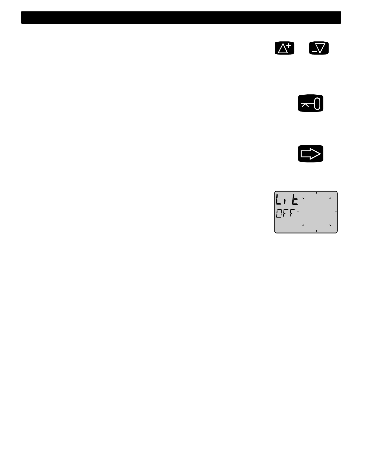
54
4.2.5 Nollställning av ett värde
Genom att trycka på UPP och NER samtidigt nollställs ett värde
4.2.6 Kalibrering
För att komma in i kalibreringsläge, håll NYCKEL nertryckt i två
sekunder. För att komma ur kalibreringsläge, tryck NYCKEL när texten
[RET] visas.
4.2.7 Belysning
Instrumentet har en orange bakgrundsbelysning för display och
tryckknappar. Belysningen är valbar i tre steg.
Tryck på FUNKTION under minst 2 sekunder så att texten [Lit] visas. Välj
belysningsnivåer, låg [LOW], medel [MID], hög [MAX] och släckt [OFF]
med UPP eller NER, avsluta med NYCKEL
Vald belysningsnivå kommer att sättas på alla instrument som är
kopplade till nätverket. Om du har en Server ansluten kan du koppla in
en strömbrytare till den för att slå på och av ljuset, för installation se
Serverns bruksanvisning.
Svenska 4: FUNKTIONER
&
> 2 sec
> 2 sec
Page 56
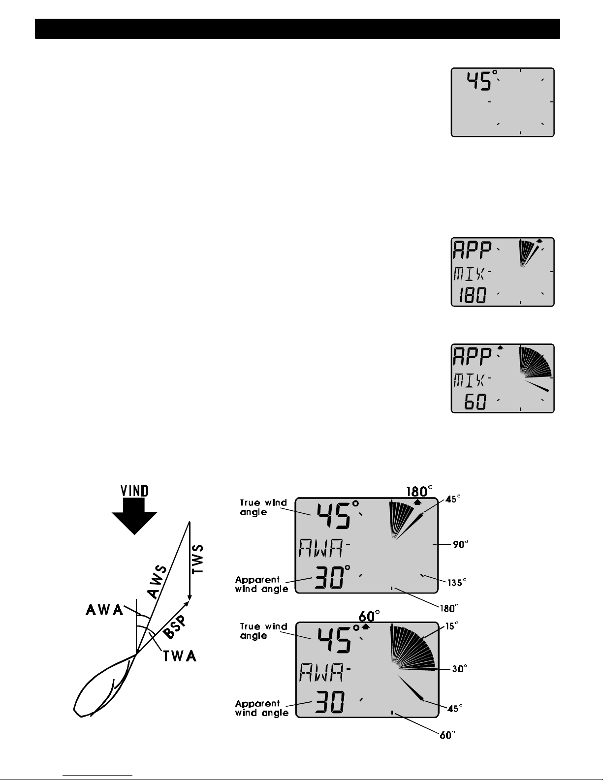
55
4.3 Huvudfunktioner
Överst visas relativ vindvinkel, [AWA] (Apparent Wind Angle).
Alternativt kan följande information visas:
Relativ vindhastighet, [AWS] (Apparent Wind Speed).
Sann vindvinkel, [TWA] (True Wind Angle) om loggivare är ansluten
Sann vindhastighet, [TWS] (True Wind Speed) om loggivare är
ansluten.
För att växla mellan dessa funktioner se C12, 5.1.2
Visas ett minus [-] tecken framför [AWA] eller [TWA] innebär det att
vinden kommer in på babords sida.
4.4 Analogfunktioner
för att växla mellan 180°° och 60°° vindskala, tryck på FUNKTION.
Inställt val markeras av en pil under motsvarande vald skala
APP Texten [APP] visar att huvudfunktionen är satt att visa
relativ vindvinkel eller vindhastighet, motsatsen är sann
[tru]. Se inställningar C12, 5.1.2
MIX 180°° Texten [MIX 180°] visar både relativ och sann vindvinkel
samtidigt utan uppförstoring.
MIX 60°° Texten [MIX 60°] visar relativ och sann vindvinkel
samtidigt i uppförstorad skala (closed hauled). Denna
funktion går att använda både under kryss och
undanvind.
Den analoga skalan kan växlas mellan 180° och 60° för att få högre
upplösning. Vid 180° är varje sektor 5°, vid 60° är varje sektor 1 2/3°. Se
exemplet nedan
4: FUNKTIONER Svenska
180°
60°
Page 57

56
4.5 Underfunktioner
Välj underfunktion med UPP eller NER
Ledtext till underliggande information visas i den mittersta raden utom vid
funktionsbyte av analog visning, då informationstext om vald
analogfunktion visas blinkande under två sekunder.
Du kan ”parkera” vald kombination av funktioner så att de automatiskt
visas vid uppstart.
Tryck samtidigt på FUNKTION och NYCKEL samtidigt och displayen
blinkar till som kvittens på att ”parkering” utförts.
4.5.1 Relativ vindhastighet [AWS]
Texten [AWS] (Apparent Wind Speed) och den relativa
vindhastigheten visas. Texten [AWS] visas växlande med information
om vald enhet,
Knop [KTS], Meter/s [M/S] eller Beufort [BF].
4.5.2 Sann vindhastighet [TWS]
Texten [TWS] (True Wind Speed) och den sanna vindhastigheten
visas. TWS är kompenserad för båtens fartvind loggivare måste vara
ansluten. Texten [TWS] visas växlande med information om vald
enhet, Knop [KTS], Meter/s [M/S] eller Beufort [BF].
4.5.3 Maximal sann vindhastighet [MAX]
För att se MAX uppmätt sann vindhastighet, tryck på NYCKEL. Efter
ca: 5sekunder återgår visningen automatiskt till [TWS]
Exemplet visar att max vindhastighet har uppmätts till 23.5m/s (eller
annan vald enhet).
Du kan ”nollställa” MAX vindhastighet genom att samtidigt trycka på UPP
och NER eller genom att bryta spänningen.
4.5.4 Båtfart mot eller med vinden [VMG]
Texten [VMG] (Velocity Made Good) och
hastighet rakt mot (eller rakt från) vinden
visas. Kräver loggivare eller att loggsignal
byglas från t.ex.Nexus logginstrument.
Information om båtfart kan även fås via
Nexus nätverk.
VMG = 0.0 knop när Du seglar med sann
vindvinkel 90 grader tvärs båten och VMG =
båtfart när Du går med motor rakt mot (eller
med) vinden. Se figur.
Svenska 4: FUNKTIONER
Page 58
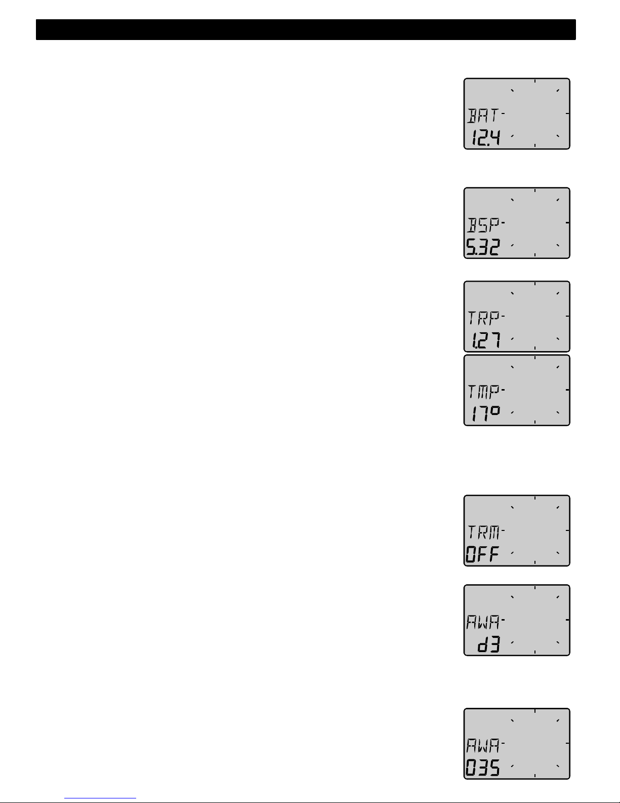
57
4.5.5 Batterispänning [BAT], tillval
Texten BAT visas och batterispänning i volt. Spänningen mäts i
instrumentet och tar inte hänsyn till ev. spänningsfall i kablar från
batteriet.
4.5.6 Båtfart [BSP], tillval
Texten [BSP] och båtfart (vattenhastighet) visas. Text [BSP] visas
växelvis med vald enhet, [KTS], [KMH] eller [MPH].
När loggivare ansluts till Wind Data instrumentet får Du tillgång till
sann vindhastighet och vindvinkel, VMG, Båtfart, Trip samt
vattentemperatur.
4.5.7 Triplog [TRP], tillval
Texten [TRP] och avverkad tripdistans visas från 0.00 till 99.9 sjömil,
kilometer eller miles, därefter från 0.00 igen. Nollställ trippdistans
genom att samtidigt trycka på UPP och NER
4.5.8 Vattentemperatur [TMP], tillval
Texten [TMP] och vattentemperatur visas i Celsius eller Farenheit.
Du kan välja bort visning av båtfart [BSP]), triplog [TRP] samt
vattentemperatur [TMP]. Se inställningar.
4.5.9 Trimfunktion för kryssvinkel eller fart, tillval
Text [TRM] och [OFF] visas när funktionen inte aktiverats. Trim
funktionen kan användas som ett hjälpmedel att hålla önskad
kryssvinkel eller till att upptäcka fartförändringar efter trim av segel
och rigg. Trimfunktionen kan t.ex.visa avvikelse från båtfart eller VMG
(båtfart rakt mot eller med vinden). Vissa funktioner som beskrivs här
kräver anslutning till Nexus nätverk.
Som första exemplet ska vi använda [TRM AWA] (TRiM Apparent
Wind Angle) som innebär val och inställning av önskad kryssvinkel.
Vindvinkelavvikelse, välj text: [TRM OFF]
Tryck samtidigt på UPP och NER, så att displayen blinkar. Välj [AWA]
med NER och avsluta med NYCKEL
Välj dämpning d0-d9 (hur snabb visningen skall vara, d0 min, d9 max)
med UPP eller NER och avsluta med NYCKEL.
Senast inställd vindvinkel visas (se även C64, 5.4.7) även inmatning
av önskad vindvinkel är möjlig.
Acceptera visad vindvinkel med NYCKEL, eller mata in ny önskad
4: FUNKTIONER Svenska
Page 59

58
vindvinkel med UPP , NER och FUNKTION innan Du trycker på NYCKEL
Inmatad vindvinkel lagras i flyktigt minne och är endast temporär. Se
även inställningar av REF i C64 där vald vindvinkel [AWA] ligger kvar i
minnet och visas automatiskt varje gång Du väljer AWA Trim.
På displayen visas nu texten [TRM] och [AWA] växlande tillsammans
med inställd vindvinkel. På den grafiska displayen visas referensen
samtidigt med relativ och sann vindvinkel, men på motsatt sida, dvs.
den sida som vinden inte kommer ifrån. Avvikelse från inställd vinkel
visas upp till +/-15°. Om avvikelsen är mellan 15° och 30° visas hela
sektorn. Avvikelse mer än +/-30° kommer att helt släcka de fyllda
sektorerna. Sektorerna fylls åter när vindvinkeln åter är inom
avvikelseområdet.
Trimma på fart, gå till funktion med text:
Tryck samtidigt på UPP och NER, så att displayen blinkar. Välj t.ex.
[BSP] med UPP och avsluta med NYCKEL
Det finns olika ”hastigheter” att trimma mot. De vanligaste är båtfart
(vattenhastighet) och VMG.
Wind Data instrumentet kan även visa avvikelse från optimal båtfart
[TBS] som beräknas med hjälp av ett program för PC där TBS fås ur
ett polardiagram för just din båt. Information om ”Target Boat Speed”
sänds från PC till NMEA 0183 ingången på Nexus Server, som i sin tur
sänder ut TBS på Nexus nätverk. På Wind Data displayen kan Du se
trim i % både digitalt och grafiskt. Varje segment motsvarar 2%.
Du kan välja ”hastigheter” att trimma mot ur följande lista:
BSP Vattenhastighet. Loggivare !
AWS Skenbar vindhastighet
TWS Sann vindhastighet Loggivare !
SOG Fart över grund Navigator !
DRF Drift Loggivare + Kompass+
Navigator !
WCV Fart mot aktivt etappmål (WP). Navigator !
VMG Fart mot eller med vinden. Loggivare !
TBS Optimal hastighet enligt polardiagram. PC+ NMEA 0183 via
Nexus Server !
OFF Funktionen avstängd.
Varje sektor motsvarar 2°
Svenska 4: FUNKTIONER
Page 60

59
Efter t.ex. val av [BSP] visas dämpning [d0] blinkande. välj dämpning
och tryck nyckel. Texten [BSP OFF] visas, vilket innebär att referens
saknas. Tryck nyckel för att sätta BSP referens.
Displayen visar nu [%] växelvis med texten [BSP] samt
hastighetsavvikelsen uttryckt i %.
Tryck på NYCKEL varje gång Du vill sätta en ny referens hastighet att
trimma mot. Du kan även ansluta en yttre trimknapp för att sätta ny
trimreferens. Se inställningar.
4.6 Funktioner med Wind Data i Nexus nätverk
Genom att ansluta Wind Data instrumentet till Nexus nätverk kan flera
nya funktioner aktiveras under förutsättningen att motsvarande givare
eller navigations information finns tillgänglig.
Wind Data instrumentet har flera tilläggsfunktioner som kan aktiveras av
användaren (se i inställningar) för att passa kappseglare såväl som och
familjeseglare.
Wind Data kan användas i ett litet nätverk tillsammans med Multi-, Logeller analoginstrumenten.
För att underlätta installation i ett litet nätverk rekommenderas
kopplingssats Art.nr. 21453. Anslutning av både vind- och loggivare sker
samlat vid t.ex.mastfoten. Därefter går endast en kabel fram till Wind
Data med signaler och spänning. Till Wind Data kan Du nu enkelt ansluta
t.ex.ett Multi Control instrument.
När Nexus Wind Data skall användas i ett större Nexus nätverk med fler
än 3 givare (log, wind, ekolod) rekommenderas att givare ansluts till
Nexus Server. Endast en kabel behövs för att överföra både spänning
och data till samtliga instrument. Dessutom ingår ett NMEA 0183
kommunikations interface för anslutning av annan navigationsutrustning.
Skall t.ex.djupinformation visas på flera instrument måste
ekolodsenheten vara ansluten till Nexus Server.
Bonusfunktion:
Om Du använder racetimern på Multi eller Log instrumentet kommer
Wind Data automatiskt att visa en grafiskt nedräknings timer, från 60s
till start.
På bilden till höger är det 45 sekunder kvar till start.
Varje sektor motsvarar 2%
4: FUNKTIONER Svenska
Page 61
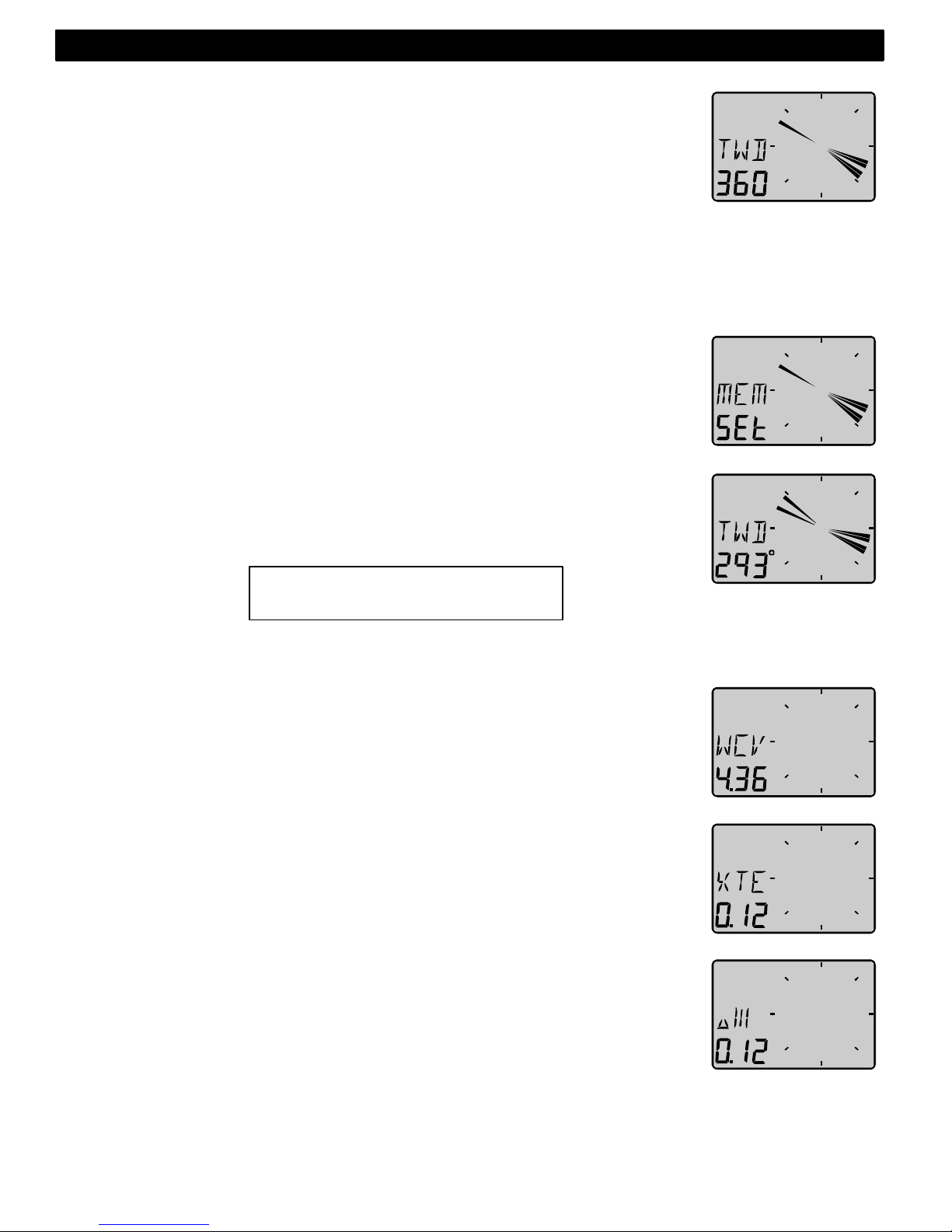
60
4.6.1 Geografisk vindriktning [TWD]
Tillvalsfunktion, NAV = On i inställningar C10.
Text [TWD] visas kortvarigt, därefter visas t.ex.[SSW], [NO], [WNW]
etc. tillsammans med numerisk vindriktning i grader.
Grafisk visning av TWD blir också tillgänglig. Tryck på FUNKTION tills
dess att [TWD 360] visas tillsammans med geografisk vindriktnings ”pil”.
Saknas kompassgivare kan en GPS navigator delvis ersätta
kompassinformationen med COG (kurs över grund) under förutsättning
att båten gör fart genom vattnet. En stillaliggande ”GPS” kommer att
orsaka slumpmässig visning av [TWD]. Ändra inställning C33 från [USE
Hdc] till [USE COG], (se 5.3.3).
Kontroll av geografisk vindvridning kan göras genom att sätta en
”markör” vid aktuell vindriktning. Markören ligger kvar tills dess att Du
sätter en ny, bryter spänningen eller kopplar ur funktionen. En
vindvridning på 5° blir därför lätt att upptäcka även efter flera timmars
segling.
Välj funktion [TWD 360°] med FUNKTION , och när texten [TWD]
blinkar blinkar trycker Du NYCKEL
Du har nu satt ”markören” vid aktuell geografisk vindriktning. Vid en
bestående vindvridning blir ”markören” kvar blinkande och verklig
riktning visas med ”fast” sektor.
4.6.2 WCV, Fart mot etappmål (märke)
Texten [WCV] visas tillsammans med fart rakt mot det aktiva
etappmålet eller märket. Kräver navigator samt tillval [NAV On] i
inställningar C14 (se 5.1.4).
4.6.3 Avvikelse från kurslinje, XTE
Texten [XTE] visas först, därefter visas en symbolisk båt (triangeln) på
sidan om ”vägen” (tre streck) tillsammans med avståndet till
kurslinjen. Kräver navigator samt tillval NAV on i inställningar C14 (se
5.1.4).
Din båt finns till höger eller vänster om kurslinjen, dvs. utefter den
ursprungliga bäringen då etappmålet valdes.
Avstånd till mittlinjen visas normalt i sjömil men kan även visas i Miles
eller Km.
När avståndet till mittlinjen är lika med noll försvinner triangel symbolen,
dvs. båten ligger mitt på vägen.
Varje sektor motsvarar 5°
Svenska 4: FUNKTIONER
Page 62

61
4.6.4 HDC / NXT , Kurs och kurs att hålla efter slag
Funktionen kräver att kompass anslutits till Nexus Server eller Kompass
instrument. Tillval NAV on i inställningar C14 (se 5.1.4).
Saknas kompass kan kompasskurs ersättas av COG (kurs över grund)
genom att välja GPS referens i inställningar C33 (se 5.3.3).
Texten [HDC] visas tillsammans med aktuell magnetisk eller sann kurs.
Efter ca 4s växlas Text över till [NXT] som visar magnetisk eller sann
kurs att hålla efter slag.
Obs !, eventuell avdrift måste alltid inkluderas i beslutet när det är dags
att slå för att hamna på rhumbline efter slag.
Efter ett slag eller gipp tar det någon minut innan värdet i [NXT] har
stabiliserats.
Funktionerna [HDC] och [NXT] växlar, men kan låsas/låsas upp med
NYCKEL
4: FUNKTIONER Svenska
Page 63
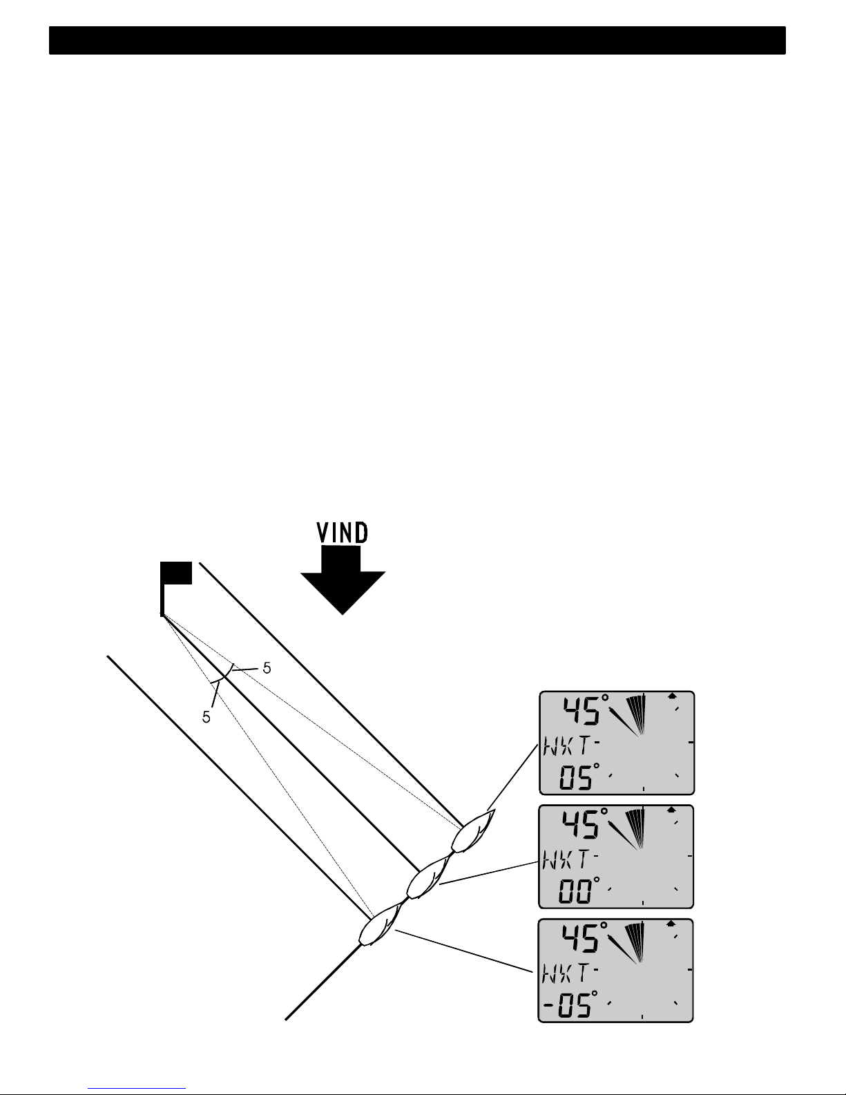
62
4.6.5 [BTW] / [NXT] , Bäring och vinkelavvikelse mot märke
Funktionen kräver kompass och navigator samt tillval NAV i inställningar
C14 (se 5.1.4).
[BTW] visar bäring till märke. [NXT] visar negativ eller positiv
slör/kryssvinkelskillnad efter gipp/slag baserat på kompasskurs eller
COG, dvs. verklig kurs över grund inklusive avdrift. Vi rekommenderar att
använda kompass. Används COG utan differentiell GPS mottagare
kommer kurs över grund att variera för mycket för att upplevas stabilt.
[BTW] och [NXT] visas växelvis.
KRYSS:
Exempel, Om Du uppskattar din avdrift till t.ex.05°. skall Du slå när [NXT]
visar 05° för att hamna på layline och därmed gå rakt på märke.
Först visas [NXT] negativt, t.ex.-14° för att sakta minska 00° och därefter
ökas bäring positivt vilket är Din ”marginal” där Du måste inkludera
uppskattad avdrift och oförutsedda vindskift.
Svenska 4: FUNKTIONER
Page 64
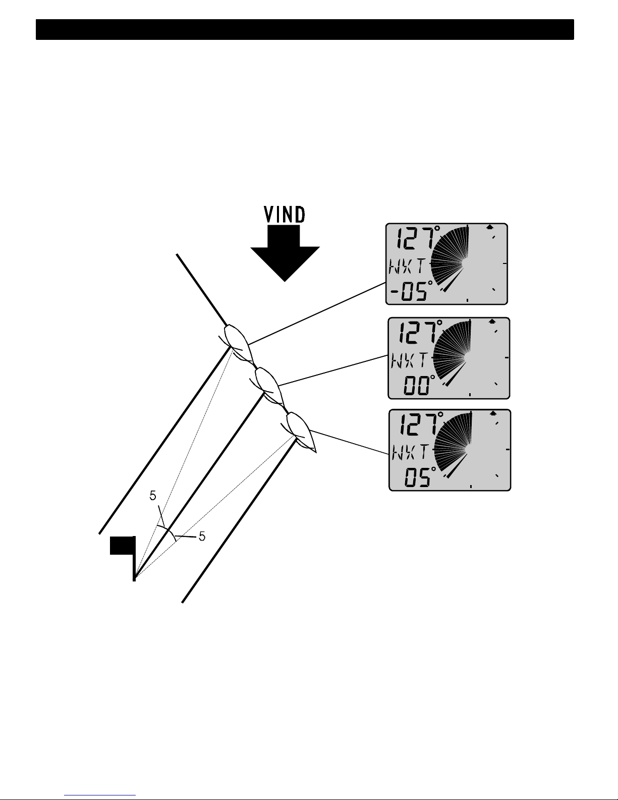
63
SLÖR:
Vid slör kan båten alltid seglas med högsta fart mot märke VMG
eftersom motsvarande slörbog efter gipp, dvs. när [NXT] visar 00°
kommer att ske så att samma optimala skärningsvinkel kan hållas ända
till märke utan större kurskorrigeringar. Funktionerna [BTW] och [NXT]
växlar, men kan låsas/låsas upp med NYCKEL
OBS! Denna funktion används endast på sista benet.
4: FUNKTIONER Svenska
Page 65
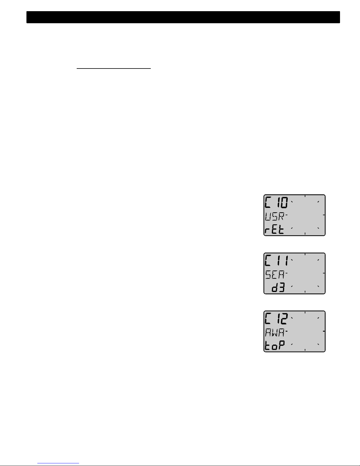
64
5 Inställningar / kalibrering
För att komma in i Inställningar skall Du hålla NYCKEL nedtryckt i minst
2 sekunder. Du återgår till normaldrift genom att trycka NYCKEL när
texten [rEt] visas.
Välj önskad huvudkalibreringsgrupp [C10- C70] genom att trycka på
FUNKTION.
C10 - C15 = USR, Användarinställningar.
C20 - C24 = BSP, Logg-givar och temperatur kalibrering.
C30 - C33 = HDC, Kompass inställning/deviation.
C50 - C64 = WND, Vindgivarinställning/kalibrering.
C70 - C74 = CON, Konfigurering av Nexus systemet.
Därefter väljs respektive inställning/kalibrering inom
huvudkalibreringsgruppen med NER och UPP .
För att ändra, tryck NYCKEL .Markören blinkar på den siffra som kan
ändras, använd (minus) NER för att minska värdet och (plus) UPP för att
öka, samt (markör) FUNKTION för att flytta till nästa siffra.. När Du är
klar trycker Du åter NYCKEL (motsvarar datorns ENTER knapp).
5.1 Användarinställning, C10
För att återgå till normaldrift tryck NYCKEL när [rEt] visas.
5.1.1 Inställning av dämpning, C11
Dämpning av vindvinkel, vindhastighet, båtfart, VMG mm., välj
mellan [d0] (0s) och [d9] (1’20)
För att ändra dämpningen tryck på NYCKEL och ändra med NER
eller UPP och lagra med NYCKEL.
5.1.2 Val av huvudinformation, C12
Inställning av vad som skall visas på de övre siffrorna. Det finns fem
olika val.
AWA Relativ vindvinkel. Loggivare krävs ej.
TWA Sann vindvinkel relativt båten. Loggivare krävs.
AWS Relativ vindhastighet. Loggivare krävs ej.
TWS Sann vindhastighet relativt båten. Loggivare krävs.
WIA Gäller endast för Nexus nätverksanslutning. Detta
systemval innebär att en automatiskt systeminställning
utförs lika C51 i Nexus Multi Control instrument.
Svenska 5: INSTÄLLNINGAR
Page 66
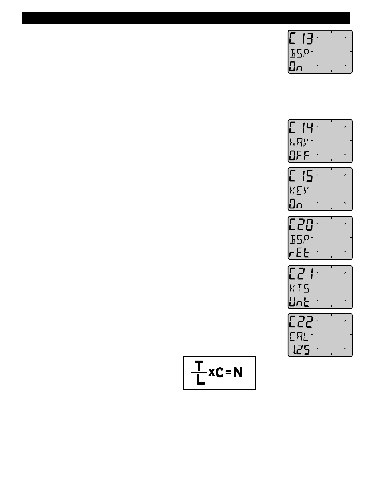
65
5.1.3 Tillval av båtfart, logg samt vattentemperatur, C13
Inställning [OFF] tar bort visning av båtfart, triplog samt
vattentemperatur för dig som föredrar att använda en separat
fartlog. Wind Data instrumentet kan användas som Server i Nexus
nätverk genom att log och vindgivare ansluts till instrumentet ,
som i sin tur sänder information om båtfart, distans och
vattentemperatur till ett eller flera Multi Control instrument. Man behöver
alltså inte se båtfart och vattentemperatur även om Wind Data
instrumentet beräknar och sänder ut informationen (se C7, kap 5.5.2)
5.1.4 Tillval av NAV funktioner, C14
NAV funktioner är endast användbart med Wind Data i ett Nexus nätverk
med kompassgivare och navigator. Inställning [NAV On] adderar
funktionerna som visas under Nexus nätverk. Se 4.6
5.1.5 Ljudsignal vid knapptryckning, C15
OFF eller On Inställning On innebär att instrumentet ”piper” vid varje
knapptryckning. Inställning OFF innebär tyst funktion.
5.2 Kalibrering av LOG, C20
För att återgå till normaldrift, tryck NYCKEL när [rEt] visas.
5.2.1 Val av enhet, C21
Välj enhet för fart, knop [KTS], km/h [K/h] eller miles/h [m/h].
5.2.2 Kalibrering av loggivare, C22
Det är viktigt att Du kalibrerar båtfarten noggrant, och när detta väl är
gjort, lagras värdena i instrumentets avbrottsfria minne.
Har Du redan rätt kalibreringsvärde i ditt Nexus Speed instrument kan
samma värde användas i Wind Data. Behöver Du göra en ny kalibrering
måste Du välja tillval C13 BSP till On för att kunna se båtfart och triplog.
Kör båten en känd distans i normalfart och jämför sedan med den distans
som trippmätaren visar. Beräkna därefter din båts kalibreringsvärde med
följande formel:
Sann distans frön sjökortet: T
Loggad distans: L
Nuvarande kalibreringsvärde: C
Nytt kalibreringsvärde: N
Om du misstänker ström i vattnet under kalibreringen bör Du köra i båda
riktningarna och därefter dividerar Du mätt distans med 2 för att
eliminera påverkan av strömt vatten.
Om Wind Data installeras med Nexus Server där båtfart redan
kalibrerats behöver ingen ny kalibrering göras.
5: INSTÄLLNINGAR Svenska
Page 67
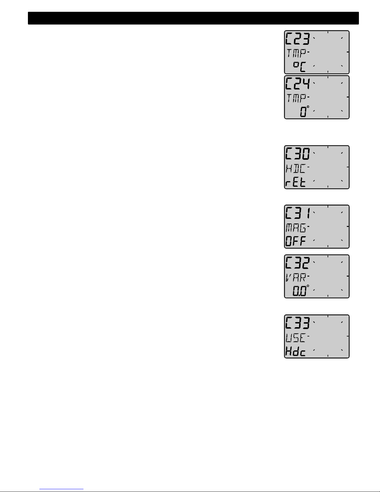
66
5.2.3 Inställning av enhet för vattentemperatur, C23
5.2.4 Välj enhet för temperatur, grader Celsius [C] eller grader
Farenheit [F]. Inställning av vattentemperatur offset, C24
Inställning av temperatur offset. Adderar inställt offset värde (+/-) till
uppmätt värde som därefter visas på displayen.
Eventuellt minustecken väljs med minus. [ - ] framför siffran.
5.3 Inställning av kompass, C30
För att återgå till normaldrift, tryck NYCKEL när [rEt] visas.
5.3.1 Inställning av sann eller magnetisk kurs, C31
Gäller endast Nexus nätverk. Välj On för att visa magnetisk bäring,
kurs och vindriktning (indikeras MAG).
Välj OFF för att visa sann bäring, kurs samt vindriktning. Kan vara
intressant om man har mycket stor missvisning på platsen.
5.3.2 Inställning av missvisning, C32
Ställ in missvisning +E eller W först, därefter storleken på den lokala
magnetiska missvisningen. Inställning medges med 1 decimals
noggrannhet vilket ger en korrekt avrundning efter kompensation.
5.3.3 Inställning av kurs referens, C33
När kompassgivare är ansluten till Nexus nätverk, Rekommenderas att
den Väljs som referens. Välj [HDC].
Välj [COG] (kurs över grund) när GPS navigator är ansluten men ej
kompassgivare.
Välj [STA] för statisk användning. Används vid fasta installationer
(sommarstuga, skidanläggning, färjeläge mm.) för att visa geografisk
vindriktning och vindhastighet. Givaren monteras i riktning norrut, men
om detta inte är möjligt justeras givaren ”elektroniskt” i Inställningar med
ADJust till att visa geografiskt riktigt.
Observera att COG, dvs. kurs över grund endast kan fungera
tillfredsställande när båten gör fart genom vattnet.
Svenska 5: INSTÄLLNINGAR
Page 68

67
5.4 Inställning / kalibrering av vind, C50
För att återgå till normaldrift, tryck NYCKEL när [rEt] visas.
5.4.1 Nexus Inställning av sann eller relativ vindvinkel, C51
Välj mellan skenbar [AWA] eller sann [TWA] vindvinkel, denna
inställning påverkar de analoga vindrepeatrarna samt de Multi
instrument som har [WIA] i sin systemsetup C63
Inställning C51 är identisk med Multi Control inställning C51.
5.4.2 Val av enhet för vindhastighet, C52
Enheten får vindhastighet kan väljas mellan [KTS] för knop, [m/s]
för meter/s samt [BF] för Beufour.
5.4.3 Vindhastighets kalibrering, C53
Detta värde är fabriksinställt på 1.50 och behöver därför inte ändras.
5.4.4 Justering av visad vindvinkel, C54
Justering av mindre vinkelfel efter montering av givaren, eller när
vindgivaren avsiktligt placerats t.ex.90° vinkelrätt mot masten.
Inställt värde adderas till vindvinkeln.
Exempel: om vindvinkeln visar +4° när Du går rakt mot vinden med
båtens motor ställer Du C54 till 356° (det är samma sak som att dra ifrån
4°).
5.4.5 Kalibreringstabell för vindgivaren, C55-C62
Se medföljande kalibrerings certifikat. För varje 45° intervall anges
ett korrektionsvärde. Värdet matas in under respektive angivet
intervall.
Efter kalibrering är vinkelfelet max +/- 1,5°
C55 000 000°
C56 045 045°
C57 090 090° Ställ in värden efter det medföljande
C58 135 135° kalibreringssertifikatet för var 45:e grad
C59 180 180°
C60 225 225°
C61 270 270°
5: INSTÄLLNINGAR Svenska
Page 69
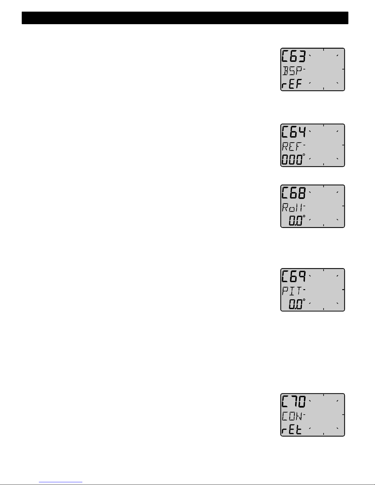
68
C62 315 315°
5.4.6 Hastighets referens, vatten- (log) eller GPS, C63
Endast för Nexus nätverk.
Inställning [BSP] innebär normal användning av loggivare (fart genom
vattnet) för att beräkna sann vind- hastighet och riktning, VMG samt
NXT funktionen tillsammans med BTW. Inställning [SOG] innebär att
fartinformation tas från GPS i stället. Tänk på att med GPS som
fartgivare krävs att båten gör viss fart för att ge tillfredsställande värden.
Används differentiell GPS ökas noggrannheten betydligt.
5.4.7 Inställning av trimreferensC64
När skenbar vindvinkel (AWA) väljs som trimreferens efter
spänningtillslag kommer värdet inställt i C64 att föreslås.
5.4.8 Inställning av krängnings offset, C68
Denna inställning är endast tillgänglig om Roll är valt i C73 (du måste
lämna kalibreringsläge och gå in igen)
Inställning av krängningsoffset. Montera först givaren enligt instruktion,
justera därefter offset så att Roll visar 00° när båten ligger lodrätt, dvs
krängning är 00°. Genom att ange ”-” framför värdet kommer visad
(och uppmätt) krängning att minskas med motsvarande värde. När
offset anges utan tecken kommer värdet att adderas till uppmätt
krängning. När givare anslutits kommer vindvinkel och vindhastighet att
kompenseras i motsvarande grad för att öka noggrannheten.
Denna givare var inte tillgänglig då denna manual skrevs.
5.4.9 Inställning av långskeppslutning offset, C69
Denna inställning är endast tillgänglig om Roll är valt i C73 (du måste
lämna kalibreringsläge och gå in igen)
Inställning av långskeppslutning offset. Montera först givaren enligt
instruktion, justera därefter offset så att Pitch visar 00° när båten ligger
lodrätt, dvs långskeppslutning är 00°. Genom att ange ”-” framför
värdet kommer visad (och uppmätt) långskeppslutning att minskas med
motsvarande värde. När offset anges utan tecken kommer värdet att
adderas till uppmätt krängning. När givare anslutits kommer vindvinkel
och vindhastighet att kompenseras i motsvarande grad för att öka
noggrannheten.
Denna givare var inte tillgänglig då denna manual skrevs.
5.5 Konfigurera Nexus, C70
För att återgå till normaldrift, tryck NYCKEL när [rEt] visas.
I CONfigurering anger Du var vind- och loggivare anslutits. Detta är
nödvändigt eftersom både Wind Data instrumentet och Nexus Server
kan sprida information om vind och fart.
Ett Wind Data instrument som anslutits till Nexus nätverk kan ta
information om både vind och fart från Nexus nätverk eller från givare
som anslutits direkt till instrumentet. Informationen sänds då vidare till
övriga Nexus anslutna instrument.
Svenska 5: INSTÄLLNINGAR
Page 70
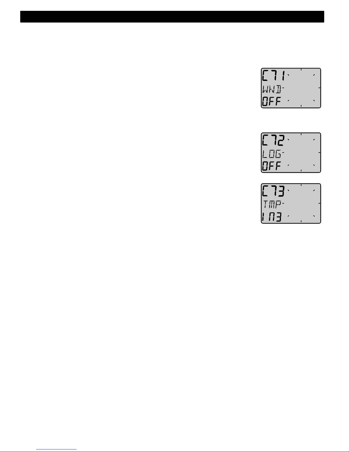
69
Obs !, om Du t.ex. konfigurerar för anslutning av loggivare i Wind Data
instrumentet, men ändå skruvar in givaren i Nexus Server kommer
varken fart, logg eller vattentemperatur att visas någonstans i Nexus
systemet.
5.5.1 Vindmaster, C71
Inställning On innebär att instrumentet är vindgivarmaster i stället för
Nexus Servern. Inställning OFF innebär att Vindgivare skall anslutas
till Nexus Server
Logg-master, C72
Inställning On innebär att instrumentet är loggivar master i stället för
Nexus Servern. Inställning OFF innebär att Loggivare skall anslutas till
Nexus Server
5.5.2 Funktionsval på skruvterminal 3, C73
Inställning och val av funktionstyp på instrumentets skruvterminal
nummer 3. Följande val kan göras:
[TMP] Standardinställning för temperaturgivare.
[TRM] Anslutning av yttre monterad STEER Pilot TRIM knapp.
[SPT] Anslutning av yttre monterad SPEED TRIM knapp.
[MOB] Anslutning av yttre monterad Man över bord (M.O.B.)
knapp. (Endast i Nexus Nätverk)
[Roll] Anslutning krängningsgivare.
När val av funktion Roll görs kan ytterligare offset justeringar göras i
kalibreringsgrupp C64. under vindinställningar C50 = WND
Genom att t.ex.ansluta loggivaren till Nexus Server blir vattentemperatur
tillgänglig på Nexus nätverk.
Väljs SPT (SPeed Trim) kommer den yttre trimknappen att aktivera ett
TRIM kommando som sänds sänds ut till samtliga SPEED Trim
instrument.
5.5.3 Anslutning av extern tryckknapp
För att både sätta styrreferens (STEER Pilot) och farttrim (SPEED Trim)
är det optimalt att ansluta en TRIM knapp för farttrim till Wind Data
instrumentet och en TRIM knapp till Nexus Server som sätter kompass
minne eller vindvinkelreferens. En sådan installation medger att både
farttrim och kurstrim kan utföras med två separata TRIM knappar.
5: INSTÄLLNINGAR Svenska
Page 71
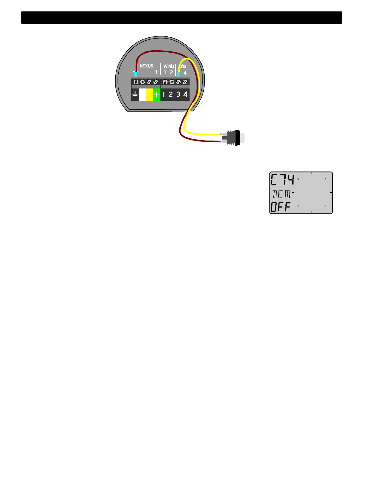
70
Inkoppling av
tryckknapp.
Koppla in en
slutande tryckknapp
mellan terminal 3
och jord. Det är
möjligt att koppla
flera tryckknappar
parallellt, t.ex en på
styrbords sida och en
på babord.
Tryckknappens
artikel nummer: 19763
5.5.4 Demo- mode, C74
Inställning av demo-mode (demonstrations läge) sker genom att
sätta [DEM] till [On]. Instrumentet visar därefter exempel på data
utan att givare anslutits. I intervaller om ca: 7s kommer text DEM att
visas för att förhindra förväxling med verkligt data om demo valts av
misstag.
Svenska 5: INSTÄLLNINGAR
Page 72

71
6 Underhåll och felsökning
6.1 Underhåll
• Rengör endast instrumenten med mild tvållösning. Använd ej
högtryckstvätt!
• Förvaring under en längre tid i sträng kyla rekommenderas ej.
• Ta bort vindgivaren från en liggande mast som förvaras över vintern.
• Applicera silikonfett på samtliga kontakter redan vid
höstupptagningen.
• Använd alltid instrumentskyddet då instrumentet ej används.
• Kontrollera anslutningar och kablar någon gång om året.
6.2 Felsökning
Innan du kontaktar Nexus agent vill vi att du kontrollerar en del saker.
Detta för att vi skall ha möjlighet att ge bra service.
• Vilka instrument som är kopplade till Nexus Nätverket, med dess
versionsnummer
• Nexus Nätverksenhets nummer för alla instrument
6.2.1 Felsökning, generellt
• Fel i elektronisk utrustning beror ofta på felaktiga anslutningar eller
inställningar.
• Att installationen är gjord enligt instruktionerna
• Att alla skruvanslutningar är väl åtdragna
• Att inte korrosion uppståt i anslutningar
• Att det inte är kontaktfel i anslutningarna
• Att batterispänningen är korrekt
• Att säkringen inte har bränt och
• Att rätt typ av säkring används
• Att inte två instrument har samma Id-nummer på Nexus Nätverket
• Att följande viktiga inställningar är korrekta: C13, C14, C33, C63, C71
och C72.
6: UNDERHÅLL Svenska
Page 73

72
6.2.2 Fel - åtgärd
1 Vindfunktioner
• Om vingivaren ger felaktiga eller ”hoppiga” värden kontrollera
anslutningar (om däckgenomföringskontakt används kontrollera den)
• Mät med en voltmätare mellan skruv 1 och jord samt skruv 2 och
jord, värdet skall ligga mellan 1.5V till 4V. (mät endast vid
vindhastighet över 3 m/s)
• Om voltmätaren visar 0V eller 5V är givaren eller anslutning felaktig.
(mät endast vid vindhastighet över 3 m/s)
2 Fartfunktioner
• C13 skall stå i [on]
• Med en voltmätare kan man kontrollera att givaren fungerar. Mät
mellan skruv 4 och jord (alla anslutningar måste vara gjorda) ta upp
givaren ur genomföringen. Vrid långsamt på paddelhjulet, halva
varvet skall voltmätaren visa 0V och halva varvet 5V
• Vid ”hoppiga värden kontrollera dämpningen (SEA) (se C11, 5.1.1)
3 Felmeddelanden
Följande felmeddelanden kan uppstå:
ERROR 2 Inget Nexus Nätverk, kontrollera anslutningar
ERROR 3 Långt uppehåll i dataöverföringen, kontrollera kablar
och Id-nummer
ERROR 10 ogiltigt Värde, t.ex. 420°
ERROR 11 Fjärrkommando som inte kan utföras
Svenska 6: UNDERHÅLL
Page 74

73
7 Specifikationer
7.1 Tekniska specifikationer
Dimensioner: Wind Data instrument: 110 x 110 mm.
Givarkabel: 25 m
Spänning: 12V DC (10-16V). Instrumentet är
skyddat mot förväxling av batteripoler.
Strömförbrukning:
Instrument: 9 mA (med max belysning 90 mA).
Vindgivare: 25 mA
Logg- och temperaturgivare: 15 mA
Temperaturområde Lagring: Från -30°C till +80°C.
Användning: Från -10°C till +70°C.
Vikt instrument: 283 g.
Vikt givare: 293 g.
CE godkännande
Alla produkter uppfyller EMC kraven för immunitet och emission Enligt
EN 50 08-1, and EN 55022.
7.2 Nexus Nätvärk
Introduktion:
Nexus Nätverket är en dubbelriktad buss med möjlighet att ansluta
många instrument. Den är en RS-485 duplex bus med möjlighet till 32
instrument anslutna samtidigt. Den höga störokänsligheten medger
användande av mycket långa kablar (upp till 1200 m).Data sänds
synkront med en startbit, 8 databitar, 1 paritetsbit samt 2 stoppbitar med
en överföringshastighet av 9600 baud. Detta ger möjligheter till mycket
snabb datauppdatering. Viss information skickas upp till 10 ggr. Per
sekund.
Användare av Nätverket:
Nexus Nätverket är öppet för nya användare och applikationer utan
licenser eller avgifter. Emellertid är Nätverket tillverkarens egendom.
Därför måste specifikationerna följas för att skydda tillverkarens
åtaganden vad beträffar prestanda och driftsäkerhet.
För de flesta applikationer är PC-interface (art.nr. 21248) ett mycket bra
hjälpmedel för att titta på och logga all data som skickas på Nätverket.
Det går även att lägga in Waypoints och rutter via PC:n. PC-interfacet är
utrustat med en anslutning till Nexus Nätverk samt en 9-polig D-sub
kontakt för anslutning till kommunikationsporten (RS-232)
7: SPECIFIKATIONER Svenska
Page 75

74
8 Andra delar i Nexus serien
Nedan finner du en förteckning över andra instrument och givare i Nexus
serien.
Art. Nr. Nexus, Kompletta Set:
20445-3 Multi Control instrument med Server
20445-1 Speed log, komplett med givare
20445-2 Ekolod komplett med givare
21033-1 GPS Navigator, komplett med instrument och antenn
21440 Wind Data instrument complete with transducer
Nexus Digitala Repeaters:
20445-4. Multi Control
21032 GPS Navigator, Nexus/NMEA
20445-5 Autopilot instrument
21210 Remote Control, Nexus fjärrkontroll och instrument
21434-1 Wind Data
Nexus Analoga Repeaters:
20550-1 Wind
20550-2 Steer Pilot
20550-6 Kompass
20550-3 Logg, 0-16 KTS
20550-4 Logg, 0-50 KTS
20550-5 Djup, 0-200 m
20550-7 Djup, 0-600 FT
20550-8 Farttrim
20550-9 Roder vinkel indikator
Nexus Givare:
20700 Logg/Temp,0 - 30 KTS, löstagbar, 8 m (26 ft) kabel
20711-2 Djup, 0.8 - 150 m (2.6-490 ft), löstagbar, 3 + 8 m
(10 + 26 ft) kabel
20721 Masttopsenhet, 22 m ( 72 ft) kabel
20860 Fluxgate Kompass, 8 m (26 ft) kabel
21000 GPS Antenn, Nexus/NMEA, fast, 10 m ( 33 ft) kabel
21117 GPS Compass XL1000, handburen
21170 GPS Navigator XL300, handburen
Svenska 8: TILLBEHÖR I NEXUS SERIEN
Page 76

75
Nexus hydrauliska Autopilot
21035 Servoenhet
21134 Pump set för hydraulisk styrning
21134 Pump set komplett med cylinder och solenoid
21036 Rodervinkelgivare
Andra Nexus tillbehör
19841 Maxi repeater via NMEA, gula siffror
19941 Maxi repeater via NMEA, röda siffror
19923 Mastfäste för en Maxi repeater
69999 Mastfäste för två Maxi repeaters
21248 Nexus PC interface. FD med 1 m (3.3 ft) kabel. Innehåller
en 3½”disc. Med mjukvara för waypoint editeringing och
data bus hantering samt NMEA interface
19763 Extern tryckknapp för Taktik och MOB funktion
21154 Högfarts Paddelhjul, upp till 40 KTS
19038 Monteringssats för invändigt montage av lodgivare
19216 Brons genomföring
18129 Instrument panel i aluminium för upp till 6 Nexus
instrument
18500 Decksgenomföringskontakt 7-polig
18501 Decksgenomföringskontakt 4-polig
20966 Skarvkontakt 4-polig (lämplig för fjärrkontroll)
67400-15 15° vinkel adapter för masttopps fäste
21453 Kopplingsbox for Wind instrument
8: TILLBEHÖR I Nexus SERIEN Svenska
Page 77

76
9 Förkortningar
Förkortning Engelsk beskrivning Svensk översättning
ADJ ADJust Justera
APP APParent Skenbar
AWA Apparent Wind Angle Skenbar vindvinkel
AWS Apparent Wind Speed Skenbar vindhastighet
BAT BATtery Batteri
BSP Boat Speed Båtens fart
BTW Bearing To Waypoint Bäring till etappmål
C Celcius Celcius
C10 Calibrate 10 Kalibrering 10
CAL Calibrate Kalibrering
CON CONfiguration Konfiguration
DEM DEMonstration Demonstration
F Farenheit Farenheit
HDC HeaDing Compass Styrkompass
KM Kilometer per hour Kilometer i timmen
KTS KnoTS Knop
LCD Liquid Crystal Display Flytande kristall fönster
LOW LOW Låg
m Metre Meter
MAG MAGnitic Magnetisk
MAX MAX Maximal
Mh Miles per hour Engelsk mil i timmen
MID MID Medel
MIX MIXture Blandad
NAV NAVigation Navigation
NXT NeXT Nästa
RET RETurn Återgå till tidigare funktion
SEA Sea Sjö. Hur grov för dämpning
SOG Speed Over Ground Fart över grund
STA STAtic Fast
TMP TeMPerature Temperatur
TRM TRiM Trim
TRP TRiP Trippmätare
tru true Sann
TWA True Wind Angle Sann vindvinkel
TWD True Wind Direction Sann vind riktning
TWS True Wind SpeedSann vindhastiget
Unt Unit Enhet
USR USeR Användare
VAR VARiation Variation/missvisning
VMG Velocity Made Good Nyttohastighet
WCV Waypoint Closure velocity Hastighet mot WP
WIA WInd Angle Vindvinkel
WND WiND calibration Vindkalibrering
XTE Cross track error Felet vinkelrätt mot vägen
- Minus Minus
_ Plus Plus
Svenask 9: FÖRKORTNINGAR
Page 78

77
GARANTI
ALLMÄNT
Alla produkter är utvecklade och tillverkade för att motsvara den yppersta bransch standarden. När
produkten är korrekt installerad, handhavd och underhållen, i enlighet med beskrivningen i produktens
manual, kommer den att bidra med många års tillförlitlig drift. Utöver produktens tekniska manual kan
också vår världsomspännande återförsäljar- och serviceorganisation bistå med ytterligare information och
assistans.
GARANTIOMFATTNING
Garantin täcker reparation av defekta delar som beror av fel hänförda till tillverkningen av produkten.
Garantin täcker reservdel samt arbetstid om produkten lämnas in och repareras i det land där produkten
inköptes. Garantiperioden framgår av manualen och börjar löpa från den dag produkten inköptes.
Ovanstående garanti är tillverkarens enda garanti, vilket innebär att ytterligare villkor ej är tillämpliga på
produkten.
GARANTIVILLKOR
• Produktens inköpskvitto med angivet inköpsdatum och ifyllt garantikort måste medfölja för att
validera garantikrav som sker enligt procedur beskriven nedan.
• Produktens garanti är inte möjlig att överföra, utan gäller endast för den ursprungliga köparen.
• Produktens garantin gäller inte i de fall serienummer saknas, felaktig installation skett, felaktigt
elsäkringsförfarande, omständighet förorsakad av felaktigt handhavande, externa orsaker såsom
modifieringar eller service utförd av annan än tillverkaren eller av denne auktoriserad distributör eller
genom användning utanför de tekniska gränsvärden som specificerats i produktens manual.
• Tillverkaren, tillverkarens distributörer och återförsäljare är inte ansvarig och kommer inte att
kompensera direkta eller indirekta skador som uppkommit p.g.a. felaktigheter i produkten.
Tillverkaren är inte heller ansvarig för person skador eller skador på tredje man som uppkommit p g
a användning av produkten.
• Tillverkaren, tillverkarens distributörer och återförsäljare är inte ansvariga för kostnader i samband
med sjötester, felsökningar i båtar, etc, oavsett om produkten är under garanti eller inte. Tillverkaren,
tillverkarens distributörer och återförsäljare bistår gärna med denna service. Nedlagda kostnader
kommer i dessa fall att debiteras köparen i enlighet med gällande priser.
• Tillverkaren, tillverkarens distributörer och återförsäljare reserverar sig rätten att, i de fall reparation
ej är möjlig att genomföra inom en rimlig tidsperiod, byta ut felaktiga returnerade produkter under
garantiperioden, med närmast motsvarande ersättningsprodukt.
GARANTIPROCEDUR
Produkten skall returneras till Tillverkaren, tillverkarens distributör eller återförsäljare i det land där
produkten inköpts. Giltiga garantikrav kommer då att ersättas utan kostnad.
Alternativt kan produkter som används i annat land än inköpslandet, lämnas in till den lokala nationella
distributören eller återförsäljaren. Giltiga garantikrav kommer då att ersättas utan kostnad. Giltiga
garantikrav kommer även då att ersättas i form av reservdelar, men arbetstid och eventuellt tillkommande
kostnader för frakt kommer att debiteras köparen i enligthet med gällande priser.
FÖRBEHÅLL
Sunt förnuft gäller vid användning av navigationsutrustning och tillverkarens produkter skall endast ses
som ett navigationshjälpmedel. Tillverkaren förbehåller sig rätten att ändra produktens specifikation.
10: GARANTI Svenska
Page 79

78
Fil id:
GARANTIKORT
SKICKAS IN TILL GENERALAGENTEN
ÄGARE:
Namn:
Adress :
Postnummer :
Land:
Produktens namn: Serie nummer:
A B C 1 2 3 4 5 6 7
Inköpsdatum:_________________________________Installationsdatum___________________________
Återförsäljarens stämpel:
Kryssa här om du inte är intresserad av information om nya produkter
Svenska 10: GARANTI
 Loading...