

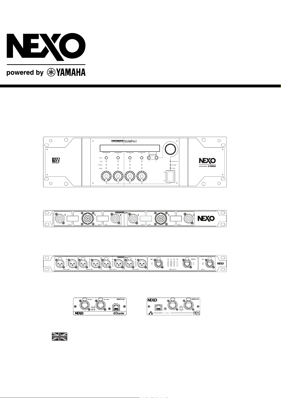
NXAMP4x1 & NXAMP4x4
Powered TDcontrollers
Digital Patching Unit
Digital Meters Unit
NXES104 / NXDT104
User Manual v2.8 (LOAD3_15)

FCC INFORMATION (U.S.A.)
1. IMPORTANT NOTICE: DO NOT MODIFY THIS UNIT!
This product, when installed as indicated in the instructions contained in this
manual, meets FCC requirements. Modifications not expressly approved by
NEXO-SA may void your authority, granted by the FCC, to use the product.
2. IMPORTANT:
When connecting this product to accessories and/or another product use only
high quality shielded cables. Cable/s supplied with this product MUST be used.
Follow all installation instructions. Failure to follow instructions could void your
FCC authorization to use this product in the USA.
3. NOTE:
This product has been tested and found to comply with the requirements listed
in FCC Regulations, Part 15 for Class “B” digital devices. Compliance with these
requirements provides a reasonable level of assurance that your use of this
product in a residential environment will not result in harmful interference with
other electronic devices. This equipment generates/uses radio frequencies and, if
not installed and used according to the instructions found in the users manual,
may cause interference harmful to the operation of other electronic devices.
* This applies only to products distributed in the United States of America.
Compliance with FCC regulations does not guarantee that interference will not
occur in all installations. If this product is found to be the source of interference,
which can be determined by turning the unit “OFF” and “ON”, please try to
eliminate the problem by using one of the following measures:
Relocate either this product or the device that is being affected by the
interference.
Utilize power outlets that are on different branch (circuit breaker or fuse) circuits
or install AC line filter/s.
In the case of radio or TV interference, relocate/reorient the antenna. If the
antenna lead-in is 300 ohm ribbon lead, change the lead-in to co-axial type
cable.
If these corrective measures do not produce satisfactory results, please contact
the local retailer authorized to distribute this type of product. If you can not
locate the appropriate retailer, please contact the After Sales department of
NEXO-SA, Parc d’Activité du Pré de la Dame Jeanne, B.P. 5, 60128 PLAILLY
The above statements apply ONLY to those products distributed by NEXO-SA or
its subsidiaries.
IMPORTANT SAFETY INSTRUCTIONS
1 Read these instructions.
2 Keep these instructions.
3 Heed all warnings.
4 Follow all instructions.
5 Do not use this apparatus near water.
6 Clean only with dry cloth.
7 Do not block any ventilation openings. Install in accordance with the
manufacturer’s instructions.
8 Do not install near any heat sources such as radiators, heat registers,
stoves, or other apparatus (including amplifiers) that produce heat.
9 Do not defeat the safety purpose of the polarized or grounding-type
plug. A polarized plug has two blades with one wider than the other. A
grounding type plug has two blades and a third grounding prong. The
wide blade or the third prong are provided for your safety. If the
PRECAUTIONS
Please read carefully before proceeding. Please keep this manual in a safe place for future reference.
WARNING
provided plug does not fit into your outlet, consult an electrician for
replacement of the obsolete outlet.
10 Protect the power cord from being walked on or pinched particularly
at plugs, convenience receptacles, and the point where they exit from
the apparatus.
11 Only use attachments/accessories specified by the manufacturer.
12 Unplug this apparatus during lightning storms or when unused for
long periods of time.
13 Refer all servicing to qualified service personnel. Servicing is
required when the apparatus has been damaged in any way, such as
power-supply cord or plug is damaged, liquid has been spilled or
objects have fallen into the apparatus, the apparatus has been exposed
to rain or moisture, does not operate normally, or has been dropped.
Always follow the basic precautions listed below to avoid the possibility of serious injury or even death from electrical shock, short-circuiting,
damages, fire or other hazards. These precautions include, but are not limited to, the following:

Power supply/Power cord
•
Only use the voltage specified as correct for the device. The required voltage is
printed on the name plate of the device.
• Use only the included power cord.
• Do not place the power cord near heat sources such as heaters or radiators, and do
not excessively bend or otherwise damage the cord, place heavy objects on it, or
place it in a position where anyone could walk on, trip over, or roll anything over it.
• Be sure to connect to an appropriate outlet with a protective grounding connection.
Improper grounding can result in electrical shock.
Do not open
• Do not open the device or attempt to disassemble the internal parts or modify them
in any way. The device contains no user-serviceable parts. If it should appear to be
malfunctioning, discontinue use immediately and have it inspected by qualified NEXO-
SA service personnel.
Water warning
• Do not expose the device to rain, use it near water or in damp or wet conditions, or
place containers on it containing liquids which might spill into any openings.
If any liquid such as water seeps into the device, turn off the power immediately and
unplug the power cord from the AC outlet. Then have the device inspected by
qualified NEXO-SA service personnel.
• Never insert or remove an electric plug with wet hands.
If you notice any abnormality
• If the power cord or plug becomes frayed or damaged, or if there is a sudden loss
of sound during use of the device, or if any unusual smells or smoke should appear to
be caused by it, immediately turn off the power switch, disconnect the electric plug
from the outlet, and have the device inspected by qualified NEXO-SA service
personnel.
• If this device should be dropped or damaged, immediately turn off the power
switch, disconnect the electric plug from the outlet, and have the device inspected by
qualified NEXO-SA service personnel.
CAUTION
Always follow the basic precautions listed below to avoid the possibility of physical injury to you or others, or damage to the device or other
property. These precautions include, but are not limited to, the following:
Power supply/Power cord
• Remove the electric plug from the outlet when the device is not to be used for
extended periods of time, or during electrical storms.
• When removing the electric plug from the device or an outlet, always hold the plug
itself and not the cord. Pulling by the cord can damage it.
• If you are using the NXAMP4X4, be sure to plug each power cord into separate
branch circuits employing separate service grounds. Plugging into the same circuit
can result in electrical shock.
• To disconnect the NXAMP4X4 from the mains, unplug both power cords.
Location
• When transporting or moving the device, always use two or more people.
Attempting to lift the device by yourself may damage your back, result in other
injury, or cause damage to the device itself.
• Before moving the device, remove all connected cables.
• When setting up the device, make sure that the AC outlet you are using is easily
accessible. If some trouble or malfunction occurs, immediately turn off the power
switch and disconnect the plug from the outlet. Even when the power switch is turned
off, electricity is still flowing to the product at the minimum level. When you are not
using the product for a long time, make sure to unplug the power cord from the wall
AC outlet.
• If this device is to be mounted in an EIA-standard rack, leave the back of the rack
open and make sure that it is at least 10 cm away from walls or surfaces. Also, if this
device is to be mounted with devices that tend to generate heat, such as power
amplifiers, be sure to keep an adequate gap between this device and the heat-
generating devices or install ventilation panels to prevent high temperatures from
developing inside this device.
Inadequate ventilation can result in overheating, possibly causing damage to the
device(s), or even fire.
• Do not use the device in a confined, poorly-ventilated location. If this device is to be
used in a small space other than an EIA-standard rack, make sure that there is
adequate space between the device and surrounding walls or other devices: at least
10 cm at the sides, 15 cm behind and 40 cm above. Inadequate ventilation can result
in overheating, possibly causing damage to the device(s), or even fire.
• Do not expose the device to excessive dust or vibrations, or extreme cold or heat
(such as in direct sunlight, near a heater, or in a car during the day) to prevent the
possibility of panel disfiguration or damage to the internal components.
• Do not place the device in an unstable position where it might accidentally fall over.
• Do not block the vents. This device has ventilation holes at the front/rear to prevent
the internal temperature from becoming too high. In particular, do not place the
device on its side or upside down. Inadequate ventilation can result in overheating,
possibly causing damage to the device(s), or even fire.
• Do not use the device in the vicinity of a TV, radio, stereo equipment, mobile
phone, or other electric devices. Doing so may result in noise, both in the device itself
and in the TV or radio next to it.
Connections
• Before connecting the device to other devices, turn off the power for all devices.
Before turning the power on or off for all devices, set all volume levels to minimum.
• Use only speaker cables for connecting speakers to the speaker jacks. Use of other
types of cables may result in fire.
Maintenance
• Inspect the cooling fans and clean them periodically. Dust and dirt can seriously
degrade the effectiveness of the cooling fan and result in malfunction or fire.
• Remove the power plug from the AC outlet when cleaning the device.
Handling caution
• When turning on the AC power in your audio system, always turn on the device
LAST, to avoid speaker damage. When turning the power off, the device should be
turned off FIRST for the same reason.
• Do not insert your fingers or hands in any gaps or openings on the device (vents…)
• Avoid inserting or dropping foreign objects (paper, plastic, metal, etc.) into any
gaps or openings on the device (vents, etc.) If this happens, turn off the power
immediately and unplug the power cord from the AC outlet. Then have the device
inspected by qualified NEXO-SA service personnel.
• Do not use the device for a long period of time at a high or uncomfortable volume
level, since this can cause permanent hearing loss. If you experience any hearing loss
or ringing in the ears, consult a physician.
• Do not rest your weight on the device or place heavy objects on it, and avoid use
excessive force on the buttons, switches or connectors.
• Do not use this device for any purpose other than driving loudspeakers.

XLR-type connectors are wired as follows (IEC60268 standard): pin 1: ground, pin 2: hot (+), and pin 3: cold (-).
Use only Neutrik NL4 plugs for connecting Speakon connectors.
NEXO-SA cannot be held responsible for damage caused by improper use or modifications to the device or data that is lost or destroyed.
• Always turn the power off when the device is not in use.
• The performance of components with moving contacts, such as switches, volume controls, and connectors, deteriorates over time. Consult qualified NEXO-SA service
personnel about replacing defective components.
• If you do not intend to rack-mount the NXAMP, attach the included rubber feet to the bottom surface of the device.
IMPORTANT NOTICE FOR THE UNITED KINGDOM
Connecting the Plug and Cord
WARNING: THIS APPARATUS MUST BE EARTHED
IMPORTANT. The wires in this mains lead are colored in accordance with the following
code:
GREEN-AND-YELLOW: EARTH
BLUE : NEUTRAL
BROWN : LIVE
As the colors of the wires in the mains lead of this apparatus may not correspond
with the colored markings identifying the terminals in your plug proceed as follows:
• This applies only to products distributed in the United Kingdom.
The wire which is colored GREEN-and-YELLOW must be connected to the terminal in
the plug which is marked by the letter E or by the safety earth symbol
GREEN or GREEN-and-YELLOW.
The wire which is colored BLUE must be connected to the terminal which is marked
with the letter N or colored BLACK.
The wire which is colored BROWN must be connected to the terminal which is marked
with the letter L or colored RED.
or colored
COMPLIANCE INFORMATION STATEMENT (DECLARATION OF CONFORMITY PROCEDURE)
1) This device may not cause harmful interference, and
2) This device must accept any interference received including interference that may cause undesired operation. See user manual instructions if interference to
radio reception is suspected.
* This applies only to products distributed in the United States of America.
EUROPEAN MODELS
Purchaser/User Information specified in EN55103-1 and EN55103-2.
Inrush Current: 16 A
Conforms to Environments: E1, E2, E3 and E4.
This mark indicates a dangerous electrically live terminal. When connecting an external wire to this terminal, it is necessary either to
have “a person who have received appropriate guidance on handling” make the connection or to use leads or a cord that have been
manufactured in such way that the connection can be made simply and without problem.

TABLE OF CONTENT
TABLE OF CONTENT
FCC INFORMATION (U.S.A.) ............................................................................................................................................ 3
IMPORTANT SAFETY INSTRUCTIONS.........................................................................................................................3
PRECAUTIONS..................................................................................................................................................................... 3
POWER SUPPLY/POWER CORD ................................................................................................................................................... 4
DO NOT OPEN ............................................................................................................................................................................4
WATER WARNING...................................................................................................................................................................... 4
IF YOU NOTICE ANY ABNORMALITY........................................................................................................................................... 4
POWER SUPPLY/POWER CORD ................................................................................................................................................ 4
LOCATION ................................................................................................................................................................................4
CONNECTIONS ......................................................................................................................................................................... 4
MAINTENANCE......................................................................................................................................................................... 4
HANDLING CAUTION ................................................................................................................................................................4
IMPORTANT NOTICE FOR THE UNITED KINGDOM................................................................................................ 6
COMPLIANCE INFORMATION STATEMENT (DECLARATION OF CONFORMITY PROCEDURE) .............. 6
EUROPEAN MODELS ......................................................................................................................................................... 6
TABLE OF CONTENT ......................................................................................................................................................... 6
NXAMP VERSUS NX242: WHAT’S NEW? ....................................................................................................................12
WHAT’S REMAINING THE SAME? ..........................................................................................................................................12
DSP CORE ...............................................................................................................................................................................12
LEVEL AND LATENCY ..............................................................................................................................................................12
SOFTWARE ..............................................................................................................................................................................12
WHAT’S CHANGED?...............................................................................................................................................................12
INTEGRATED AMPLIFIER ..........................................................................................................................................................12
COMPUTING RESOURCES .........................................................................................................................................................13
FOUR SEPARATE INPUTS ..........................................................................................................................................................13
POWER SUPPLY........................................................................................................................................................................ 13
ETHERSOUND™ OPTIONAL BOARD.......................................................................................................................................... 13
DANTE™ OPTIONAL BOARD .................................................................................................................................................... 13
OPTIONAL DMU UNIT.............................................................................................................................................................14
OPTIONAL DPU UNIT ..............................................................................................................................................................14
QUICK START....................................................................................................................................................................15
FRONT PANEL DESCRIPTION.................................................................................................................................................. 15
(1) POWER SWITCH.................................................................................................................................................................. 15
(2) AMPLIFIER INDICATORS .....................................................................................................................................................15
(3) LCD DISPLAY ....................................................................................................................................................................16
(4) ENCODER........................................................................................................................................................................... 16
(5) NAVIGATION BUTTONS (A & B)......................................................................................................................................... 16
(6) VOLUME INDICATORS ........................................................................................................................................................16
(7) MUTE BUTTONS .................................................................................................................................................................16
(8) SELECT BUTTONS............................................................................................................................................................... 16
PAGE 6 OF 140

TABLE OF CONTENT
(9) CHANNEL INDICATORS .......................................................................................................................................................17
(10) AIR INTAKES ....................................................................................................................................................................17
(11) SCREW HOLES FOR HANDLES............................................................................................................................................17
BACK PANELS DESCRIPTION ..................................................................................................................................................18
(1) MAINS CONNECTORS..........................................................................................................................................................18
(2) BALANCED AUDIO INPUTS WITH LINK.................................................................................................................................18
(3) EXPANSION SLOT ...............................................................................................................................................................19
(4) POWER OUTPUTS ................................................................................................................................................................19
(5) RS-232 PORT .....................................................................................................................................................................19
(6) GPIO PORT ........................................................................................................................................................................20
(7) REAR END MOUNTING HOLES .............................................................................................................................................20
BASIC FUNCTIONS ..................................................................................................................................................................20
RESET......................................................................................................................................................................................20
SELECTING CABINET FAMILY ...................................................................................................................................................20
SELECT YOUR CABINET SET-UP................................................................................................................................................21
USING THE AMPLIFIER WITHOUT THE TDCONTROLLER FUNCTIONALITY..................................................................................21
BACK TO DEFAULT ..................................................................................................................................................................21
AUTO SAVE..............................................................................................................................................................................21
ENTER THE DOWNLOAD MODE.................................................................................................................................................21
WHAT’S INSIDE THE CARTON BOX............................................................................................................................22
SETTING-UP ADVICE.......................................................................................................................................................23
EARTH CONNECTION..............................................................................................................................................................23
MAINS SETTING......................................................................................................................................................................23
MOUNTING THE NXAMP IN A RACK (GROUNDING, SHIELDING & SAFETY ISSUES) ...........................................................24
USING THE NXAMP WITHOUT A RACK ................................................................................................................................26
FUSES......................................................................................................................................................................................26
ELECTROMAGNETIC ENVIRONMENTS ...................................................................................................................................26
ANALOGUE INPUT SIGNAL CABLES ........................................................................................................................................26
NXAMP POWER OUTPUTS WIRING .......................................................................................................................................28
GENERAL DESCRIPTION................................................................................................................................................29
GLOBAL ARCHITECTURE .......................................................................................................................................................29
NXAMP4X1 GLOBAL ARCHITECTURE ....................................................................................................................................29
NXAMP4X4 GLOBAL ARCHITECTURE ....................................................................................................................................29
POWER SUPPLY BLOCK ...........................................................................................................................................................30
ANALOG INPUT BLOCK ............................................................................................................................................................31
CONTROL BLOCK .....................................................................................................................................................................31
POWER AMPLIFIER BLOCKS......................................................................................................................................................32
POWER OUTPUTS BLOCK ..........................................................................................................................................................32
USER INTERFACE BLOCK..........................................................................................................................................................33
COMMUNICATION BLOCK ........................................................................................................................................................33
EXPANSION SLOT BLOCK .........................................................................................................................................................34
BLOCK DIAGRAM DESCRIPTION ................................................................................................................................36
PATCHING AND ROUTING (1) .................................................................................................................................................37
DELAY & POLARITY INVERSION (2) ......................................................................................................................................37
FACTORY SET-UP DELAY .........................................................................................................................................................37
USER SET-UP DELAY ................................................................................................................................................................37
EQUALISATION & FILTERING................................................................................................................................................37
SUBSONIC AND VHF FILTERING (3).........................................................................................................................................37
EQUALISING WIDEBAND ACOUSTICAL RESPONSE (3) ...............................................................................................................38
USER SET-UP, ARRAY EQ (4) ....................................................................................................................................................38
EQUALISING SINGLE COMPONENT RESPONSE AND NXSTREAM PROCESSING (5) ...................................................................38
PAGE 7 OF 140

TABLE OF CONTENT
CROSSOVER SECTION (6).........................................................................................................................................................38
POST PROTECTION EQ AND LOW PASS (27) (28) ...................................................................................................................... 38
GAIN SECTION (29).................................................................................................................................................................. 38
PROTECTIONS ........................................................................................................................................................................39
SOURCE SIGNALS FOR PROTECTION ALGORITHMS (25) ............................................................................................................ 39
DISPLACEMENT CONTROL (7) (8) (9).......................................................................................................................................39
MECHANICAL STRESS CONTROL (10) (11) ............................................................................................................................... 39
HF DISPLACEMENT CONTROL (12)........................................................................................................................................... 40
HF ACCELERATION CONTROL (13) ..........................................................................................................................................40
GLOBAL PURPOSE VCEQ (14) ................................................................................................................................................40
LOUDSPEAKER PEAK LIMITERS (15) ........................................................................................................................................ 40
TEMPERATURE CONTROL (16) (17) .........................................................................................................................................40
INTERCHANNEL REGULATION (19) ..........................................................................................................................................41
AMPLIFIER PEAK CURRENT LIMITER (20)................................................................................................................................. 41
AMPLIFIER INTEGRATE CURRENT LIMITER (21) ....................................................................................................................... 41
AMPLIFIER PEAK VOLTAGE LIMITER (22)................................................................................................................................. 41
AMPLIFIER SHORT CIRCUIT DETECTOR (24) ............................................................................................................................. 41
MENU DESCRIPTION.......................................................................................................................................................42
CHANGING CABINET FAMILY ............................................................................................................................................... 43
ADJUSTING VOLUME .............................................................................................................................................................44
ADJUSTING DELAY ................................................................................................................................................................45
ADJUSTING GAIN ...................................................................................................................................................................45
ADJUSTING ARRAY EQ .........................................................................................................................................................46
ADJUSTING HEADROOM ........................................................................................................................................................ 47
HEADROOM CONCEPT.............................................................................................................................................................. 47
OPTIONS MENU...................................................................................................................................................................... 49
SYSTEM CONFIG ......................................................................................................................................................................49
INPUT PATCH .......................................................................................................................................................................... 54
SAVE/RECALL USER SETUPS .................................................................................................................................................... 59
SECURITY................................................................................................................................................................................ 61
GPIO MODE............................................................................................................................................................................ 62
LOAD MONITOR ......................................................................................................................................................................70
MISCELLANEOUS..................................................................................................................................................................... 72
INSTALLATION RECOMMENDATIONS .....................................................................................................................74
AUDIO CHAIN RECOMMENDATIONS .....................................................................................................................................74
ABOUT « LOUDSPEAKER MANAGEMENT DEVICES » ............................................................................................................... 74
OPERATING SUB’S FED THROUGH AN AUX OUTPUT ...............................................................................................................74
OPERATION OF MULTIPLE POWERED TDCONTROLLERS ..........................................................................................................74
SYSTEM ALIGNMENT ............................................................................................................................................................. 74
GEOMETRICAL ALIGNMENT.....................................................................................................................................................75
MEASURING AND ALIGNING PHASE IN THE OVERLAPPING REGION ...........................................................................................75
NXES104 EXPANSION BOARD, REMOTE CONTROL AND ASIO DRIVER .........................................................77
NXES104 PHYSICAL DESCRIPTION....................................................................................................................................... 77
(1) ETHERSOUND™ IN PORT ..................................................................................................................................................78
(2) ETHERSOUND™ NETWORK STATUS LEDS......................................................................................................................... 78
(3) ETHERSOUND™ OUT PORT .............................................................................................................................................. 78
(4) REMOTE ES100 PORT ........................................................................................................................................................ 78
VARIOUS ETHERSOUND™ DEVICES DESCRIPTION ............................................................................................................... 79
MONO-DIRECTIONAL, NON ES100 DEVICES ............................................................................................................................ 79
BI-DIRECTIONAL, NON ES100 DEVICES ...................................................................................................................................79
ES100 DEVICES .......................................................................................................................................................................79
ES100/SPKR DEVICES..............................................................................................................................................................80
ETHERNET ADDITIONAL HARDWARE.................................................................................................................................... 80
PAGE 8 OF 140

TABLE OF CONTENT
HUBS .......................................................................................................................................................................................80
SWITCHES................................................................................................................................................................................80
WIRELESS LAN.......................................................................................................................................................................80
ETHERNET CABLES ..................................................................................................................................................................81
FIBER OPTIC ............................................................................................................................................................................83
INSTALLATION INSIDE THE NXAMP ....................................................................................................................................83
NXAMP WITH NXES104 CONTROL PAGE IN ESMONITOR™ SOFTWARE ...........................................................................83
COMPATIBILITY ISSUES ...........................................................................................................................................................84
GRAPHICAL USER INTERFACE ..................................................................................................................................................84
(1) VIRTUAL FRONT PANEL ......................................................................................................................................................85
(2) INPUT METERS....................................................................................................................................................................85
(3) STANDBY BUTTON .............................................................................................................................................................86
(4) DELAY UNIT ......................................................................................................................................................................86
(5) SECURITY LOCK.................................................................................................................................................................86
(6) GROUP ...............................................................................................................................................................................86
(7) CHANNELS NAME ...............................................................................................................................................................87
(8) INPUT PATCH .....................................................................................................................................................................88
(9) OUTPUT METERS ................................................................................................................................................................88
(10) MUTE BUTTON .................................................................................................................................................................88
(11) VOLUME CONTROL...........................................................................................................................................................88
(12) GAIN CONTROL ................................................................................................................................................................88
(13) DELAY SETTINGS .............................................................................................................................................................88
(14) ARRAYEQ SETTINGS........................................................................................................................................................89
(15) HEADROOM SETTINGS ......................................................................................................................................................89
(16) AMPLIFIER STATUS ..........................................................................................................................................................89
(17) OVERMUTE ......................................................................................................................................................................89
(18) NOTES..............................................................................................................................................................................90
(19) ALIAS...............................................................................................................................................................................90
(20) HARDWARE AND FIRMWARE INFORMATION.....................................................................................................................90
(21) ASIO MODE ....................................................................................................................................................................90
(22) SCENE ..............................................................................................................................................................................92
(23) CABINET SETUP ...............................................................................................................................................................93
(24) VIRTUAL FRONT PANEL SIZE ............................................................................................................................................94
NXAMP AND NXES104 WITH THE ASIO STREAMER .........................................................................................................94
WHAT ARE ASIO / ASIO STREAMER? .....................................................................................................................................94
INSTALLING THE ASIO STREAMER ..........................................................................................................................................95
SETTING UP THE NXAMP FOR ASIO MODE ............................................................................................................................95
SETTING UP THE ASIOCONTROLPANEL....................................................................................................................................95
SETTING UP THE ASIO HOST ...................................................................................................................................................96
NXDT104 EXPANSION BOARD, DANTE™ PATCHING AND REMOTE CONTROL ...........................................97
NXDT104 PHYSICAL DESCRIPTION ......................................................................................................................................97
(1) DANTE™ PRIMARY PORT ..................................................................................................................................................97
(2) NETWORK PORTS STATUS LEDS........................................................................................................................................98
(3) DANTE™ SECONDARY PORT .............................................................................................................................................98
(4) REMOTE PORT ....................................................................................................................................................................98
ETHERNET ADDITIONAL HARDWARE....................................................................................................................................98
HUBS .......................................................................................................................................................................................99
SWITCHES................................................................................................................................................................................99
WIRELESS LAN.......................................................................................................................................................................99
ETHERNET CABLES AND FIBER OPTIC.......................................................................................................................................99
INSTALLATION INSIDE THE NXAMP ....................................................................................................................................99
NXAMP WITH NXDT104 CONTROL PAGE IN DANTE™ CONTROLLER.............................................................................100
ROUTING AUDIO INSIDE A DANTE™ NETWORK .....................................................................................................................100
ADVANCED OPTION OF THE DANTE™ CONTROLLER..............................................................................................................101
DEVICE VIEW ........................................................................................................................................................................102
NXAMP WITH NXDT104 CONTROL PAGE IN ESMONITOR™ SOFTWARE ........................................................................104
PAGE 9 OF 140

TABLE OF CONTENT
ENABLING REMOTE CONTROL OF NXAMP WITH NXDT104 IN ESMONITOR™ ....................................................................105
GRAPHICAL USER INTERFACE ................................................................................................................................................105
(1) DANTE ID SETUP ......................................................................................................................................................... 106
MORE INFORMATION ABOUT SETTING UP A DANTE™ NETWORK...................................................................................... 106
DMU DIGITAL METERS UNIT FOR NXAMP............................................................................................................107
FRONT PANEL DESCRIPTION................................................................................................................................................ 107
(1) ANALOG INPUTS WITH LINK .........................................................................................................................................107
(2) INPUT VIEW METER ......................................................................................................................................................107
(3) NETWORK INPUTS ........................................................................................................................................................ 107
BACK PANEL DESCRIPTION.................................................................................................................................................. 108
(1) NETWORK OUTPUTS.....................................................................................................................................................108
(2) ANALOG OUTPUTS .......................................................................................................................................................108
(3) GPIO PORT .................................................................................................................................................................. 108
OPERATING THE DPU .........................................................................................................................................................108
CONNECTIONS AND START UP................................................................................................................................................ 109
DPU DIGITAL PATCHING UNIT FOR NXAMP......................................................................................................... 111
FRONT PANEL DESCRIPTION................................................................................................................................................ 111
(1) SPEAKON® 4 POLES OUTPUT ...................................................................................................................................... 111
(2) SPEAKON® 8 POLES OUTPUT ...................................................................................................................................... 111
(3) LCD DISPLAY ..............................................................................................................................................................111
BACK PANEL DESCRIPTION.................................................................................................................................................. 112
(1) MAINS CONNECTORS ................................................................................................................................................... 112
(2) SPEAKON® 4 INPUTS .................................................................................................................................................. 112
(3) RS232 PORT ................................................................................................................................................................ 113
OPERATING THE DPU .........................................................................................................................................................113
CONNECTIONS AND START UP................................................................................................................................................ 113
DPU FRONT PANEL CONNECTORS ROUTING........................................................................................................................... 114
DPU DISPLAYED INFORMATION ............................................................................................................................................ 114
UNUSED FRONT PANEL CONNECTORS ....................................................................................................................................116
LINKING SEVERAL DPU TOGETHER....................................................................................................................................... 117
NXWIN4 SOFTWARE FOR NXAMP FIRMWARE UPGRADE................................................................................119
WHAT YOU NEED TO UPGRADE YOUR NXAMP..................................................................................................................119
SERIAL PORT UPGRADE.......................................................................................................................................................... 119
NETWORK PORT UPGRADE (FROM NXES104 OR NXDT104) ................................................................................................ 120
CONNECT THE COMPUTER TO THE NXAMP ...................................................................................................................... 120
(1) REMOTE ES100 PORT ...................................................................................................................................................... 120
(2) ETHERSOUND™ IN PORT.................................................................................................................................................121
(3) RS-232 SERIAL PORT.......................................................................................................................................................121
(4) DANTE™ PRIMARY, SECONDARY OR REMOTE PORT.........................................................................................................121
PUT THE NXAMP IN DOWNLOAD MODE............................................................................................................................. 121
USING THE NXWIN4 SOFTWARE ......................................................................................................................................... 122
BEGIN THE UPGRADE.............................................................................................................................................................123
USING THE CONTROLLER AFTER A FIRMWARE UPDATE..................................................................................................... 124
CHOOSING A CABINET SETUP................................................................................................................................................. 124
SELECTING CABINET FAMILY................................................................................................................................................. 124
SELECT YOUR CABINET SET-UP.............................................................................................................................................. 124
NXAMP TECHNICAL SPECIFICATIONS...................................................................................................................126
NXAMP THERMAL DISSIPATION AND CURRENT DRAWN................................................................................ 127
NXAMP DIMENSIONS .................................................................................................................................................... 128
PAGE 10 OF 140

TABLE OF CONTENT
DMU TECHNICAL SPECIFICATIONS ........................................................................................................................129
DPU TECHNICAL SPECIFICATIONS..........................................................................................................................129
DMU DIMENSIONS..........................................................................................................................................................130
DPU DIMENSIONS ...........................................................................................................................................................130
NXES104 & NXDT104 TECHNICAL SPECIFICATIONS...........................................................................................131
APPLICATION NOTE: DRIVING THE SUB FROM THE AUX SEND....................................................................132
WHAT IS THE PHASE RELATION BETWEEN THE AUX AND MAIN OUTPUT OF YOUR DESK? ...................................................132
WHY IT IS UNLIKELY THE AUX AND MAIN HAVE THE SAME PHASE? ...................................................................................132
CONSEQUENCES OF BADLY ALIGNED SYSTEMS ......................................................................................................................132
PRECAUTIONS & CHECK ........................................................................................................................................................133
APPENDIX A: LIST OF SUPPORTED PRESETS (LOAD3_15).................................................................................135
APPENDIX B: HOW IS MEASURED THE AMPLIFIER POWER? .........................................................................136
GENERAL DESCRIPTION OF THE SETUP ...............................................................................................................................136
PRECISION OF THE MEASUREMENT .....................................................................................................................................137
MEASUREMENT METHOD.....................................................................................................................................................137
USABLE MAINS CORD IN EUROPE ............................................................................................................................138
ROHS CERTIFICATE ......................................................................................................................................................139
USER NOTES.....................................................................................................................................................................140
PAGE 11 OF 140

NXAMP VERSUS NX242: WHAT’S NEW?
NXAMP versus NX242: What’s new?
The NXAMP Powered TDcontroller has been designed in order to provide ascendant
compatibility with its predecessor – the NX242 Digital TDcontroller.
What’s remaining the same?
DSP core
The DSP used in the NXAMP are from the same family (same core) than the one used in
NX242 and on the NXTENSION board. Thus algorithms such as EQ will perform exactly the
same on both platforms. However, since LOAD3_01, the firmware uses the full potential of
the NXAMP’s higher computing ressources (see further), leading to discontinuing
simultaneous firmware release for both platforms.
Level and latency
to analog as well as global gain were identical on NXAMP on one side and NX242 with 26dB
gain amplifiers on the other side. In LOAD2_55 and above, to minimize global latency
especially for wedge applications, the base latency of the NXAMP has been reduced to its
minimum, thus loosing the compatibility with NX242 family of products. Now with
LOAD3_01 and above, the setups themselves offer different level, EQ, crossover points and
protection algorithm which cannot fit into older hardware like NX242 or NX242ES4.
Software
Basic Menus and functions are more or less the same; only little learning curve is needed
to go from the NX242 to the NXAMP.
LOAD3_15 does not fit other hardware than NXAMP. Please use LOAD2_58 as
latest version for NX242 (with or without NXTENSION) and LOAD2_48 as latest
version for NX241 (with or without NXTENSION-CAI).
Note however, that the NXAMP can’t be flashed with LOADs prior to 2_46, and must always
use NXWIN 4 software embedded with the firmware in the archive file.
What’s changed?
WARNING! Up to LOAD2_54, global delays due to analog to digital and/or digital
Integrated amplifier
The most notable improvement is the integration of the amplifier module that will simplify
the cabling from the user point of view but also allow a much more efficient integration of
loudspeaker controller with the amplifier needs. Thus the digital controller becomes also an
amplifier controller. This is not simply two units inside the same box, but a powerful use of
the DSP resources for both cabinets and amplifier being driven.
PAGE 12 OF 140

NXAMP VERSUS NX242: WHAT’S NEW?
Computing resources
The DSP resources have been multiply by 3.5 between the NX242ES4 and the NXAMP (so
it means by 7 between the NX242 and the NXAMP). This will ensure that the NXAMP will
have enough DSP resources to deal with many years of algorithm improvements. Other
key components like CPU speed, memory quantities and so on have been also upgraded.
Four separate inputs
The analog input stage now offers 4 separate symmetrical inputs, each on XLR with link
(due to the 3U , on NXAMP4x1, or 4U , on NXAMP4x4 height of the unit, there is plenty of
space for connectors at the back). All the inputs offer considerable 28 dBu headroom
(same than on the NX242). These analog inputs leads to last generation 24 bits converters
running at 48 KHz (like on the NX242-ES4).
Power supply
The NXAMP4x1 Powered TDcontroller uses three separate switch mode power supplies
(SMPS) whereas the NXAMP4x4 uses 5. A first small power supply is used for powering the
TDcontroller digital board, and to initiate the power amp. The other big power supplies are
used for power amplifiers:
• On NXAMP4x1, channels 1 & 2 (on one power supply) and for channel 3 and 4 (on
the other one).
• On NXAMP4x4, each channel has its own large power supply.
These large power supplies are precisely tailored to work around a precise Mains voltage,
so separate model of NXAMP exists for 110 ~ 120 Volts on one side (these are models
NXAMP4x1U and NXAMP4x4U), and for 220 ~ 240 Volts on the other side (these are
models NXAMP4x1C and NXAMP4x4C).
However, a Dual voltage version of the NXAMP4x4 exists to accommodate from both 110 ~
120 Volts and 220 ~ 240 Volts (model NXAMP4x4W). The unit will automatically switch to
the correct mode on startup.
Ethersound™ optional board
The NXAMP is designed to accept the optional NXES104 board witch offers four digital
inputs among a bidirectional 2x 64 channels Ethersound™ ES100 network. This optional
board uses the new NEXO slot which prevents the necessity to open the top panel of the
amplifier for installing the board. NXAMP firmware upgrade can also be performed through
this Ethersound™ port. Finally, the ASIO functionality of the NXES104 allows streaming 4
channels of 24 bits/ 48 KHz audio directly from the Ethernet port of a PC computer.
Dante™ optional board
The NXAMP can also accept the optional NXDT104 board witch offers four digital inputs
from a Dante™ network. This optional board uses also the NEXO slot. NXAMP firmware
upgrade can also be performed through this network card. Finally, the ASIO driver for
Dante™ networks allows streaming 4 channels of 24 bits/ 48 KHz audio directly from the
PAGE 13 OF 140

NXAMP VERSUS NX242: WHAT’S NEW?
Ethernet port of a PC/MAC computer to any number of NXAMP with NXDT104 on the
network.
N.B.: Use LOAD3_11 or better for NXDT104 support.
Optional DMU unit
The DMU (Digital Meters Unit) is an optional 1U device that can be used together with the
NXAMP powered TDcontroller to ease the metering of input channels. This unit provides 8 x
level meters, one per analog input plus one per digital input from slot, plus status LEDs for
network ports.
N.B.: Use LOAD3_11 or better for DMU support.
Optional DPU unit
The DPU (Digital Patching Unit) is an optional 1U device that can be used together with the
NXAMP powered TDcontroller to ease the patching of any Nexo speaker. This unit will
automatically route the amplifier output channels to the correct pins pair of the Speakon 4
or Speakon 8 connectors on its front panel.
N.B.: Use LOAD3_11 or better for DPU support.
PAGE 14 OF 140
Quick Start
This section will allow you to quickly understand the basic functions of this product. If you
already know the previous NEXO digital TDcontrollers, such as NX241 or NX242, you may
be able to use the NXAMP Powered TDcontroller quickly as it has been designed with a
similar user interface. However please devote some attention to reading the user manual.
A better understanding of specific features of the NXAMP Powered TDcontroller will enable
you to operate your system to its full potential.
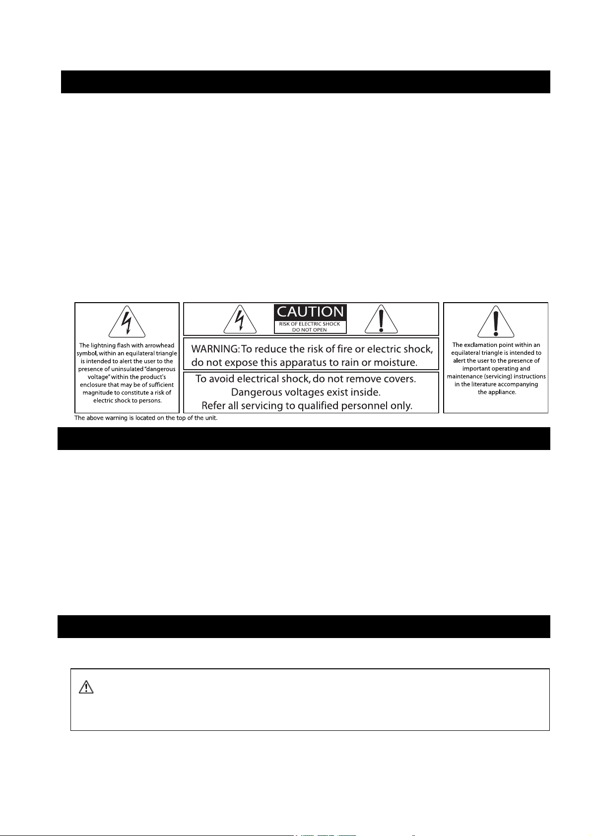
Front panel description
QUICK START
10
NB: NXAMP4X1 is shown here, but NXAMP4X4 is similar, except the model name and the global height of the unit.
8 7 6 5
3
9
1
4 2
11
(1) Power switch
Put the switch in the upper position to turn the power on. Put it down to power the
amplifier off. Please note that even in the ‘Off’ position, high voltage is still present in some
part of the amplifier, as long as it is connected to mains. Even if it is in the 'Off' position,
the amplifier will consume a minimal current.
If you plan to use remote control to turn the amplifier ‘On’ or ‘Stand-by’, then you must
first turn this power switch to the ‘On’ position. No operation is possible when the power
switch is on the ‘Off’ position.
(2) Amplifier indicators
These Three LEDs above the power switch indicate the status of the amplifier. The two first
LEDs (Power and Stand-by) indicate the power status of the amplifier:
• If both are off, the amplifier is powered off.
• If Power is lit, the amplifier is in use.
• If Stand-by is blinking, the amplifier is in stand-by.
PAGE 15 OF 140

QUICK START
Stand-by mode consumes slightly more current than in Power off mode, but allows the
amplifier to be brought back from Stand-by to power on mode through remote control.
The last LED, ‘Amp Protect’ reflects the protection status of the amplifier. If this LED is lit, it
signifies that the amplifier is reducing or muting one or several outputs due to malfunctions
as overheating, output DC, short circuitry … In combination with other LEDs indicators and
LCD display the cause of the problem will be clearly displayed. Please see further for more
details. Please also note that the Amp Protect LED will light while the amplifiers power
supplies are starting.
(3) LCD display
This large and easily readable 2 x 40 characters display will allow the user to quickly setup
the amplifier. Please note that in stand-by mode the backlight of the LCD remains on even
if nothing is displayed.
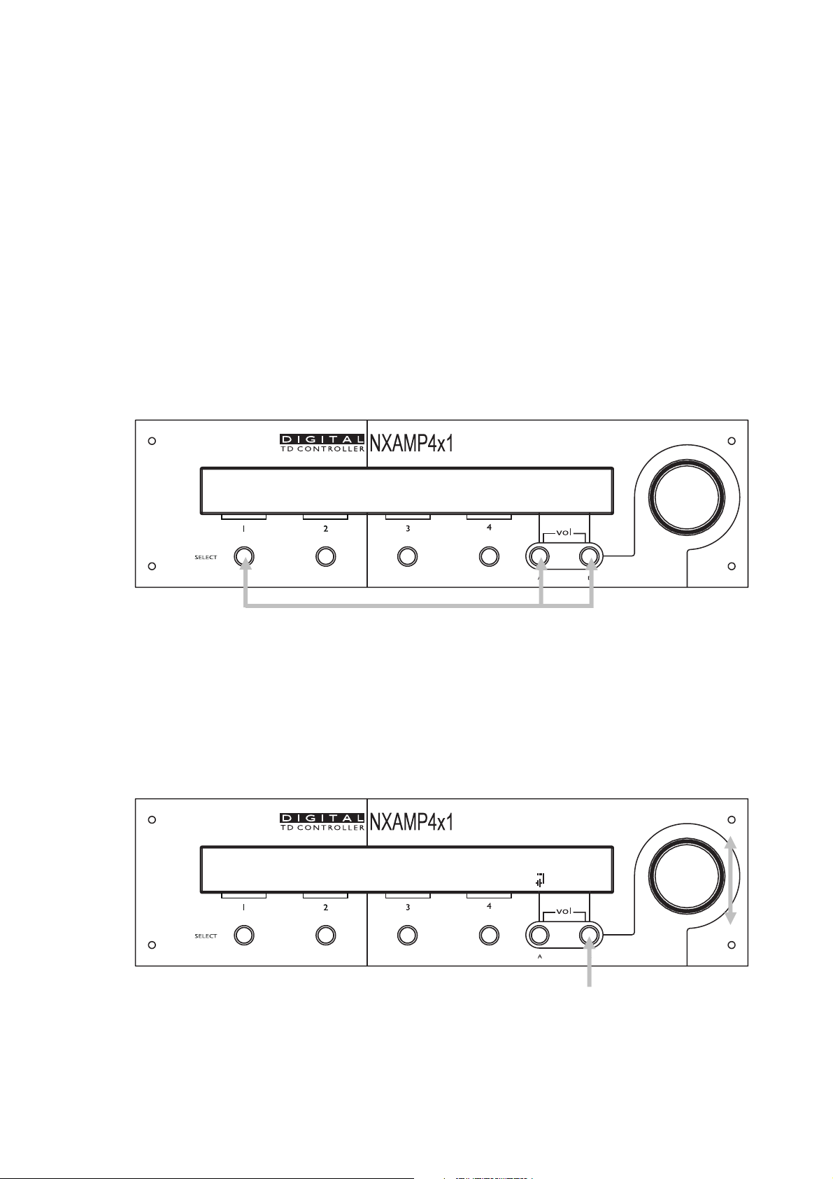
(4) Encoder
The default function of the encoder is to adjust the volume of the amplifier. But depending
on the current menu displayed on the LCD, other functions can be affected, such as delay
adjustment or speaker setup selection.
(5) Navigation buttons (A & B)
These two buttons are used most of the time to navigate through the menus. However,
depending on the LCD display, they can be used for a specific purpose.
Anytime, pressing the two buttons simultaneously will instantly enter the “Volume” menu,
allowing the user to adjust the volume for each channel using the encoder.
(6) Volume indicators
These surrounding LEDs will indicate the position of the volume control for each channel,
similar to the position given by analog potentiometers on classical amplifiers. If a channel is
muted, corresponding Mute button will lit red, but the position of the volume control will
blink alternatively for that channel, allowing the user to know what will be the level once
the channel is unmuted.
(7) Mute buttons
Whatever the current menu is, pressing the mute button will set or release the mute of the
chosen channel. The button will turn to red if the channel is muted.
(8) Select buttons
Use the select buttons to choose the channel on which you want to adjust parameters with
the encoder. In most of the menus, the bottom line of the LCD is used to indicate the
cabinet name for each channel. If this name is between brackets, it means that the
channel is selected. Turning the encoder will then have an effect on this channel.
PAGE 16 OF 140
QUICK START
(9) Channel indicators
For each channel, you have three LEDs indicator. The ‘Sense’ LED will light to green when a
certain level of current is detected on the output, meaning that a cabinet is connected and
that some signal is flowing to it. The ‘Protect’ LED will light to yellow if the TDcontroller is
applying a VCEQ protection on that channel (see further for details). The ‘Peak’ LED will
light to red to indicate that the peak limiter is working to protect the amplifier.
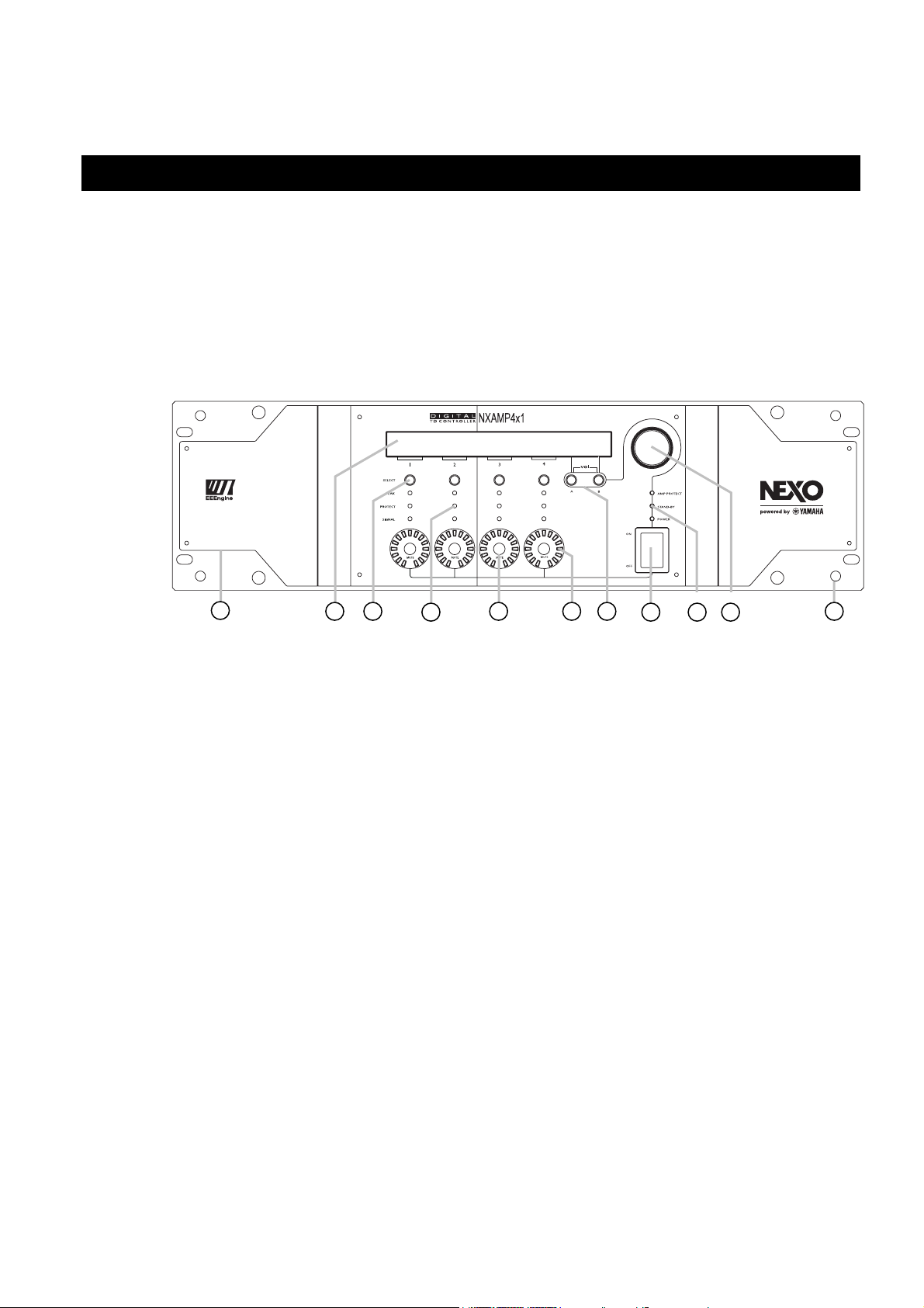
(10) Air intakes
The NXAMP uses forced-air cooling. The variable speed cooling fan draws air in from the
front and exhausts it through the rear. Please be sure that you do not block the air intakes
or exhaust vents.
Please be sure not to mix inside the same rack amplifiers with opposite air flow.
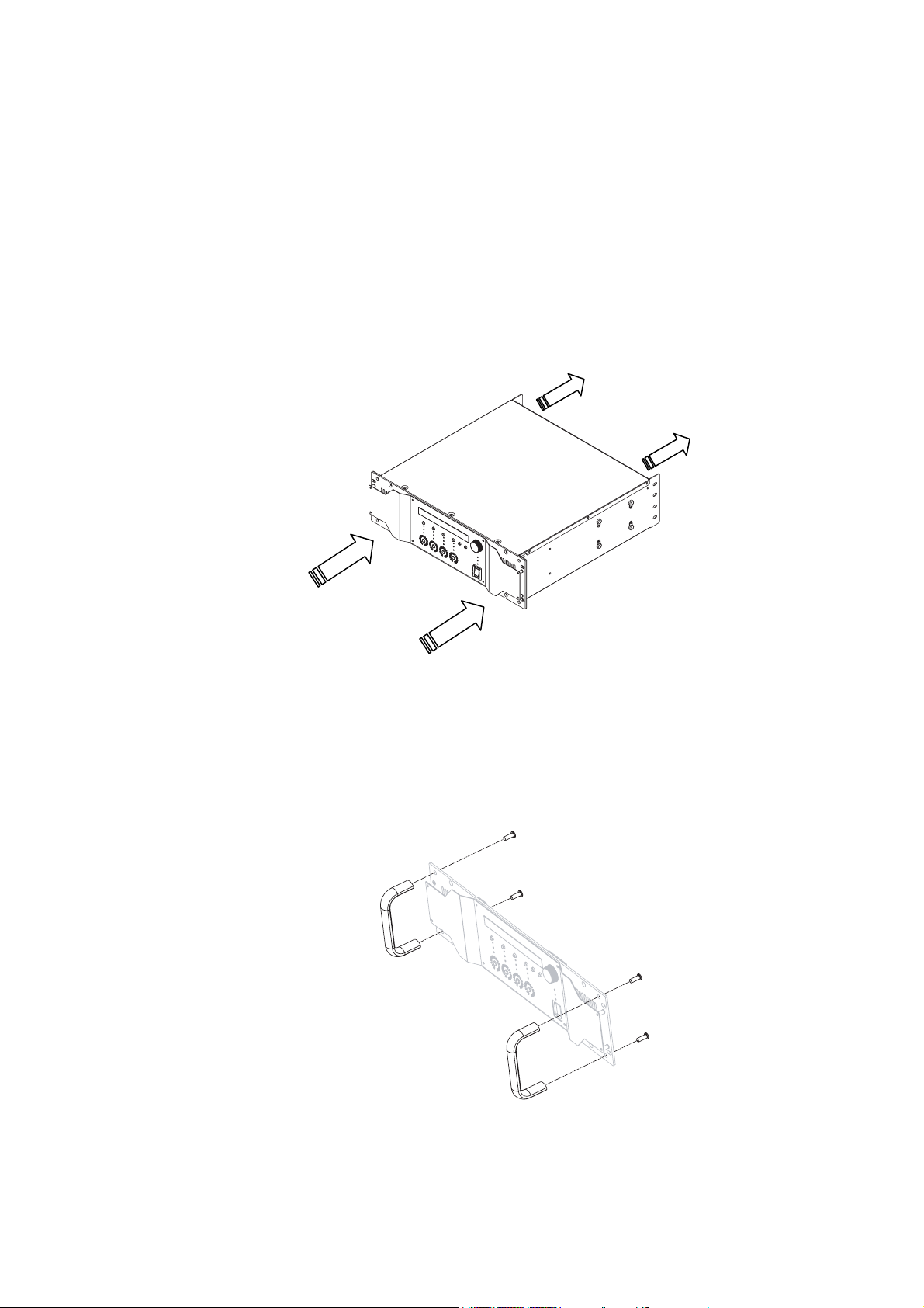
(11) Screw holes for handles
These four screw holes are for the optional handles. Fix the handles to the amplifier using
the flat-head screws included with the handles (Screw driver or key TORX X20 is needed).
NB: Separate handle models exist for NXAMP4x1 and NXAMP4x4
PAGE 17 OF 140
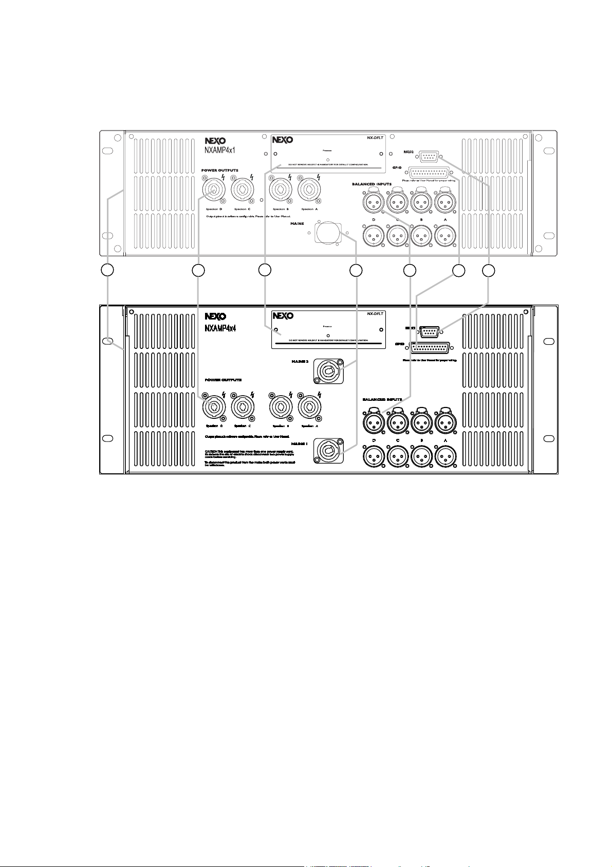
Back panels description
7
QUICK START
4
3
1 2
5 6
(1) Mains connectors
This is the mains input for the NXAMP. There is one mains plug on NXAMP4x1 and two
mains plug on NXAMP4x4.
• On NXAMP4x1, the plug is a Powercon 20A for the 100 ~ 120 Volts model (ref.
NXAMP4x1U) and a standard IEC 3 pin for the 220 Volts model (ref. NXAMP4x1C).
• On NXAMP4x4, the plugs are two Powercon 30A for the 100 ~ 120 Volts model (ref.
NXAMP4x4U) or the 110 ~ 120 / 220 ~ 240 Volts model (ref. NXAMP4x4W) and two
Powercon 20A for the 220 Volts model (ref. NXAMP4x4C).
The amplifier requires high-power so that it can demand high current from the AC service.
Connections must be properly rated for reliable operation. See specification part for details.
(2) Balanced audio inputs with link
For each of the four analog audio inputs you will find an XLR3 female input connector, and
also an XLR3 male connector in parallel for sending back the input signal to another unit.
PAGE 18 OF 140
QUICK START
(3) Expansion slot
This slot is used for extra audio inputs and remote control. See further in the manual for
details about the available options.
Since July 2009, all NXAMP4x1s and NXAMP4x4s are shipped with an expansion card fitted
in, the NX-DFLT card. This card prevents output noises when main AC power feeding
NXAMPs is brutally shutdown. NX-DFLT card should always be fitted in when no other
expansion card is used. The “Presence” LED on the NX-DFLT card shows that the card is
running properly. It will light when the amplifier is powered ON (also in Stand-by mode).
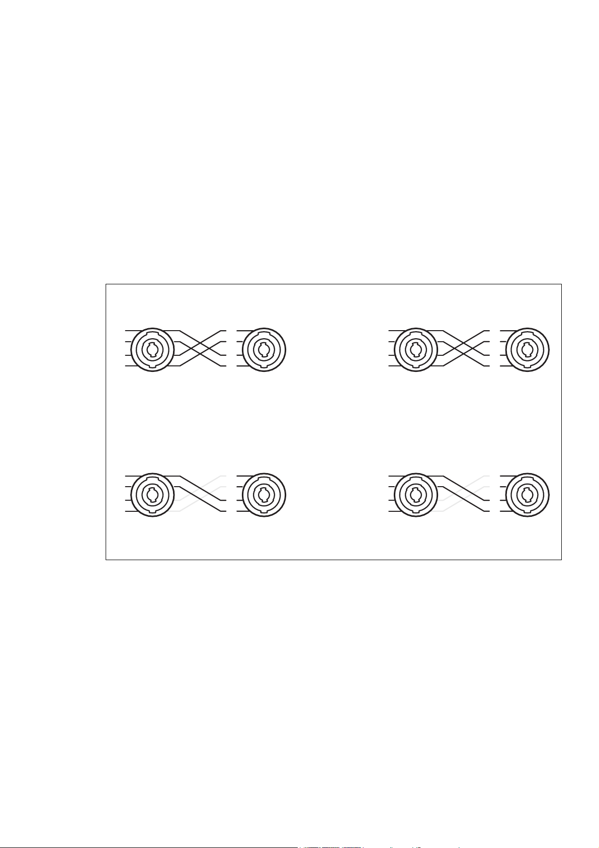
(4) Power outputs
Use Neutrik NL4 cable plug into these ports for safely connecting the power amplifier
outputs to the cabinets.
The output routing is always done this way for 4 channels mode:
Speakon A Speakon B
1+
1-
2+
2-
1+
1-
2+
2-
Speakon C Speakon D
1+
1-
2+
2-
1+
1-
2+
2-
Please note the symmetry between speakon A/B and C/D. Also you can notice that
Speakon B is always reverse of Speakon A (and same for D and C).
The output routing is always done this way in bridge mode:
Speakon A Speakon B
1+
1-
2+
2-
1+
1-
2+
2-
Speakon C Speakon D
1+
1-
2+
2-
1+
1-
2+
2-
Gray lines shows the points of the speakon physically connected to the amplifier output but
unused.
NB: The routing from DSP channels (from 1 to 4 on the front panel) and the output speakon (from A to D on the
back panel) is done automatically regarding setup configuration. See Input Patch menu further in the manual.
(5) RS-232 port
Through this serial port, you can upload a new firmware, which adds new functionalities
and new cabinets’ setups, or connect a NEXO DPU (Digital Patching Unit) device. See
further for details about the update procedure and the DPU connection.
PAGE 19 OF 140
(6) GPIO port
This GPIO port is used for interfacing the amplifier to security system, or to allow a basic
remote control of the unit. NEXO DMU (Digital Meters Unit) device also connects here.
(7) Rear end mounting holes
If the NXAMP is to be rack mounted and transported frequently, be sure to support the
rear end of the unit with mounting hardware that matches the size of the rack used.
Basic functions
Reset
You can reset the unit without powering off by simultaneously depressing buttons A, B &
‘Select CH1’ for 3 seconds at least.
QUICK START
0. FLAT - NO PROTN.
~
[4 ch amplifier] ~
(For 3 seconds)
Selecting cabinet family
Simultaneously depressing A & B buttons at power up or during device RESET accesses the
System Change menu. Keep the A & B Buttons held until Load revision disappears from
screen (approx. 2 seconds). This will allow the selection of any cabinet in any family. Using
the rotary encoder, scroll through the configurations and press B to load the required
settings.
42. GeoD PA WB
~
~
Back1-3 Front2-4 OK
PAGE 20 OF 140
QUICK START
Select your cabinet set-up
In the Options menu, choose Systm Config, and you will be able to choose among the
different set-ups within the same cabinet family. (i.e. you don't have to modify the
amplifier to cabinet wiring). Press All button and all setups will be available for selection.
Using the amplifier without the TDcontroller functionality
If you want to use the amplifier without the TDcontroller, just choose the “FLAT mode”
setup. In this mode, no EQ and no protection is applied to the cabinets. Please note that
the amplifier will still have 0.5 ms analog input to analog output latency in that mode
(warning, this latency is not the same than a NX242 TDcontroller in flat mode, see
introduction for compensating values).
In Flat mode, full amplifier digital protections are still available, and some functionality like
volume control, input patching, mute, delay, gain and ArrayEQ are working. Remote
control can be used as well.
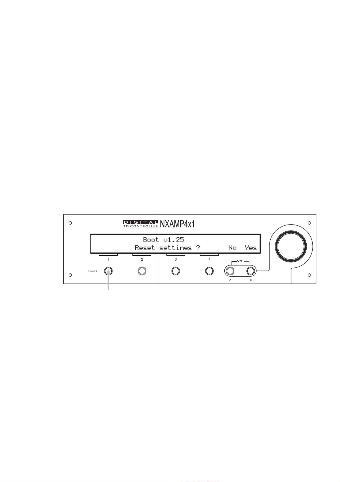
Back to default
Startup the amplifier with the ‘Select CH1’ button down and you will have the possibility
to reset the settings to default (except if the local controls have been locked, see further).
Auto save
The current set-up is automatically saved three seconds after the last change of a
parameter. At power up the last saved settings are restored.
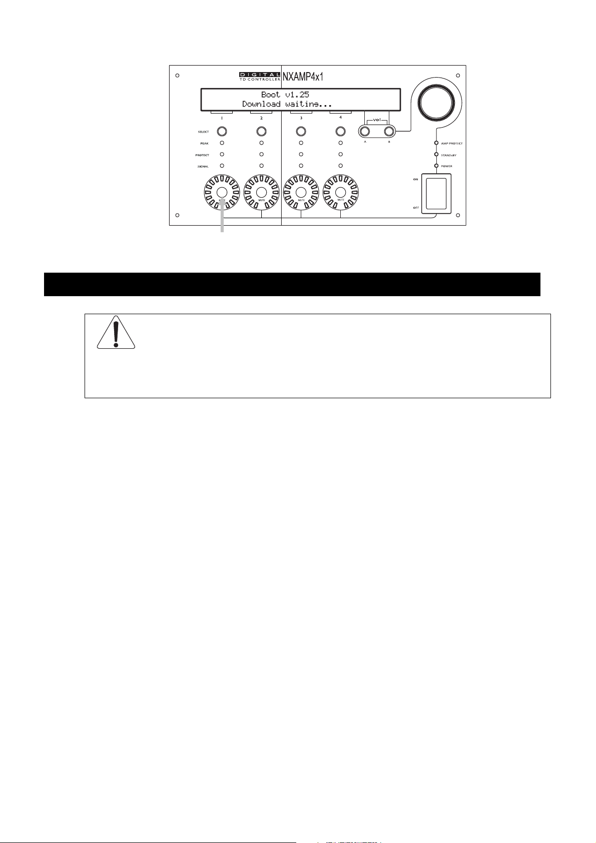
Enter the download mode
Keep the ‘Mute 1’ button down during boot up will enter the download mode. See further
for connection to the computer and download software (Nxwin) description.
PAGE 21 OF 140
What’s inside the carton box
WHAT’S INSIDE THE CARTON BOX
WARNING! The shipping weight of the NXAMP4x1 (U or C version) is nearly 21 Kg
(46 lb). The shipping weight of the NXAMP4x4 (U,C or Wversion) is nearly 30 Kg (66 lb).
Because of the large size of the carton box it is recommended to manipulate the box with
two persons.
Open the box with care to prevent damage on the content. Inside you will find:
• 1 x NXAMP Quick start guide (32 pages, 7 languages)
• 4 x Rubber pad
• 1 x NXAMP Powered TDcontroller with NX-DFLT card fitted
• 1 x Mains cord (for NXAMP4x1) or 2 x Mains cord (for NXAMP4x4)
• 1 x CD-ROM containing manuals and product brochures for the whole NEXO range.
N.B.: The provided mains cord is Chinese type for NXAMP4x1C or NXAMP4x4C (220 ~ 240
Volts version) and US type for NXAMP4x1U or NXAMP4x4U (100 ~ 120 Volts version) or
NXAMP4x4W (110 ~ 120 / 220 ~ 240 Volts version).
PAGE 22 OF 140
Setting-Up Advice
Earth connection
WARNING! THIS APPLIANCE MUST BE EARTHED.
The green and yellow wire of the mains cord must always be connected to an installation
safety earth or ground. The earth is essential for personal safety as well as the correct
installation of the system, and is internally connected to all exposed metal surfaces. Any
rack framework into which this unit may be mounted is assumed to be connected to the
same grounding circuit.
Mains setting
NEXO NXAMP Powered TDcontrollers exists under two references for NXAMP4x1 and three
references for NXAMP4x4:
SETTING-UP ADVICE
NXAMP Reference Mains Voltage Mains current
NXAMP4x1U 100 to 120 Volts Max 20 Amps
NXAMP4x1C 220 to 240 Volts Max 10 Amps
NXAMP4x4U 100 to 120 Volts Max 2x 30 Amps
NXAMP4x4C 220 to 240 Volts Max 2x 16 Amps
110 to 120 Volts Max 2x 30 Amps
NXAMP4x4W
220 to 240 Volts Max 2x 16 Amps
Each model applies to various safety standards only when use with the correct mains
voltage. Therefore, the amplifier won’t start (or will stop working) if the mains voltage is
getting out of the following min and max limits:
NXAMP Reference Mains Minimum Voltage Mains Maximum Voltage
NXAMP4x1U or
NXAMP4x4U
NXAMP4x1C or
NXAMP4x4C
60 Volts 150 Volts
150 Volts 288 Volts
PAGE 23 OF 140
SETTING-UP ADVICE
For the NXAMP4x4W this is slightly different; the unit is sensing the mains voltage on
power up, and then will choose to boot either in “110 Volts” mode or “220 Volts” mode.
Once the NXAMP4x4W has startup up in one of the two modes, it will be locked to the
corresponding voltage range till next power up.
NXAMP4x4W Mains settings
Mains Voltage when power up Mains Minimum Voltage
during use
60 to 140 Volts 60 Volts 150 Volts
140 to 160 Volts The NXAMP will not start up
160 to 288 Volts 150 Volts 288 Volts
N.B.: for all NXAMP powered TDcontroller, the maximum amplifier output voltage is
proportional to the mains voltage.
Mounting the NXAMP in a rack (Grounding, shielding & safety issues)
The NXAMP Powered TDcontroller is intended for rack mounting. The only accessible part
during use shall be the front panel of the unit. Any space above or under the TDcontroller
shall be obstructed with a blank panel.
The rack is a free grounding and shielding structure and it provides extra shielding.
Therefore, it is desirable that the screws used to fix the NXAMP Powered TDcontroller in the
frame or rack provides an electrical contact between the chassis of the TDcontroller and
the rack.
Mains Minimum Voltage
during use
The primary reason for grounding is safety. Conformance to the applicable requirements of
the authorities having jurisdiction is, of course, mandatory. However, grounding also has
an impact on electromagnetic compatibility. From the EMC point of view, it is desirable to
have a low impedance ground network, as a current flowing in the ground network will
then produce low voltage in the network. A low impedance network can be obtained using
a multipoint ground scheme, with as many closed ground loops as is economically possible.
Because of the amplifier weight, it is mandatory to fix the amplifier both from the front
panel and from the rear ears. The picture bellow shows the dimensions between the rack
holes on the front panel.
PAGE 24 OF 140
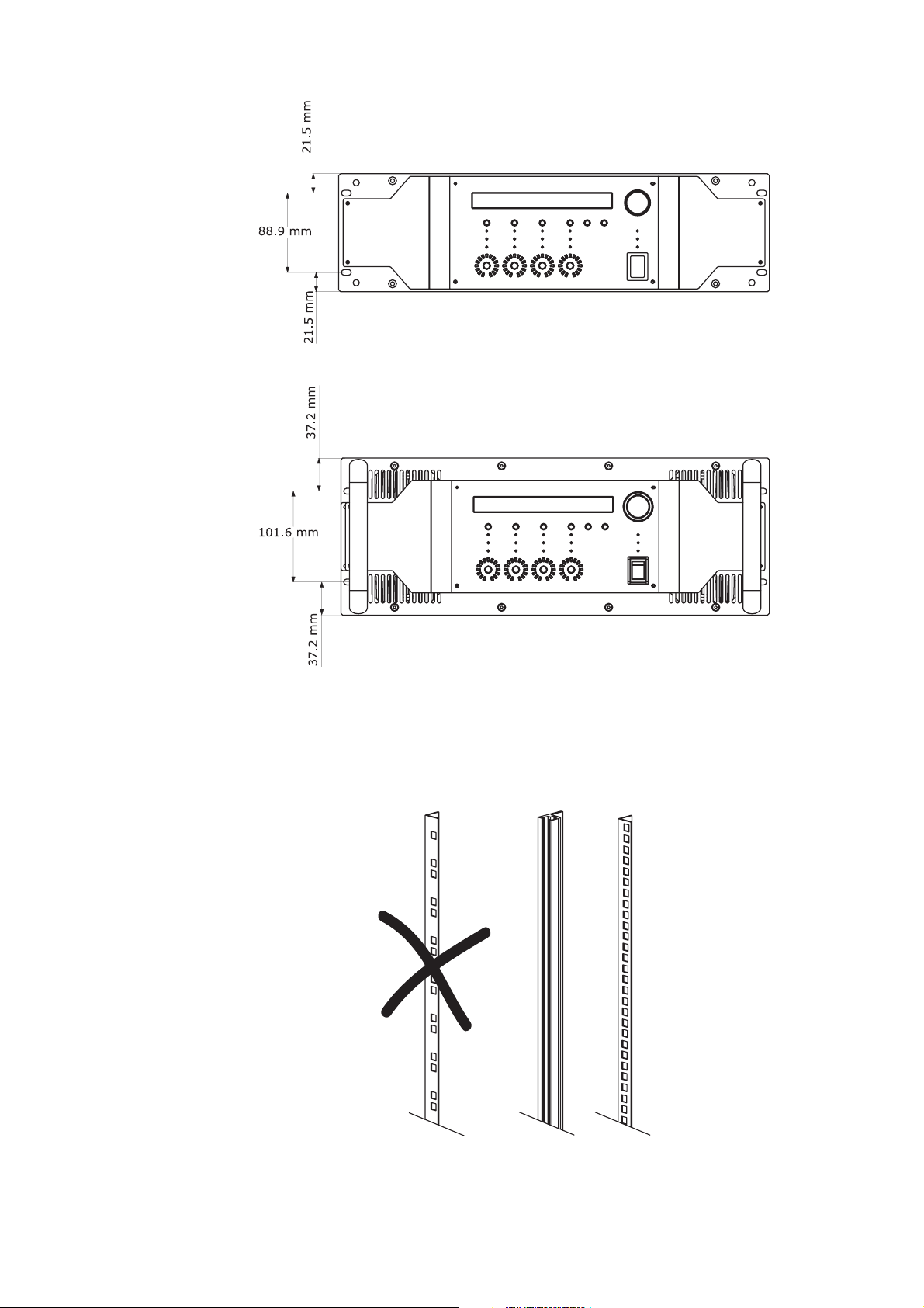
SETTING-UP ADVICE
NXAMP4x1 rack holes position
NXAMP4x4 rack holes position
With NXAMP4x1, because of this layout, it is not possible to use some rack rails with 2
holes per rack unit (see picture bellow), because you will loose ½ U of rack space on the
top and bottom of the amplifier. Thus continuous rack rails or with 4 holes per rack unit
should be used.
PAGE 25 OF 140

Using the NXAMP without a rack
If you do not put the NXAMP into a rack, then it is mandatory to use the four rubber pads
enclosed into the amplifier carton box. These auto adhesive pads should be stuck on each
corner of the bottom of the amplifier. Without these rubber pads, some internal
components can be damaged when there is a shock (for example dropping the amplifier on
a table).
Fuses
The fuses provided in the unit will not blow during normal operation. If one of the
fuses blows it means that the Powered TDcontroller has malfunctioned. This fuse must only
be changed by NEXO certified service personnel. In any case do not replace the fuse with a
non-certified NEXO fuse, as this will invalidate the NEXO warranty.
CAUTION!
SETTING-UP ADVICE
This servicing instruction is for use by qualified service personnel only. To reduce the risk of
electric shock, do not perform any servicing other than that contained in the operating
instructions unless you are qualified to do so.
Electromagnetic environments
The emission (this word describes all types of electromagnetic noise radiated by the
equipment) requirements which have been applied to Nexo’s Powered TDcontrollers are the
stringent requirements of the “Commercial and light industrial environment” of the product
family EMC standard for emission.
The immunity (this word describes the ability to cope with electromagnetic disturbance
generated by other items and natural phenomena) requirements that we have considered
exceed those applicable to the “Commercial and light industrial environment” of the
product family EMC standard for immunity. In order to provide a further safety margin, we
recommend that you do not operate the Powered TDcontrollers in the presence of
electromagnetic interference exceeding half of the limits found in this standard.
These two EMC standards are those applicable to pro-audio equipment for the
implementation of the “EMC directive”.
Analogue input signal cables
Analogue signals should be connected to the input ports of the NXAMP Powered
TDcontroller via shielded twisted pair or Starquad cable fitted with XLR connectors on the
NXAMP side. We recommend the use of low transfer impedance cables with a braided
shield and transfer impedance below 10 mΩ/m.
The NXAMP Powered TDcontroller is intended to be used with symmetrical (balanced)
sources (for instance a mixer, see figure bellow). You can see that the TDcontroller
provides a low impedance path between pin 1 of its XLR connectors and its chassis. The
PAGE 26 OF 140
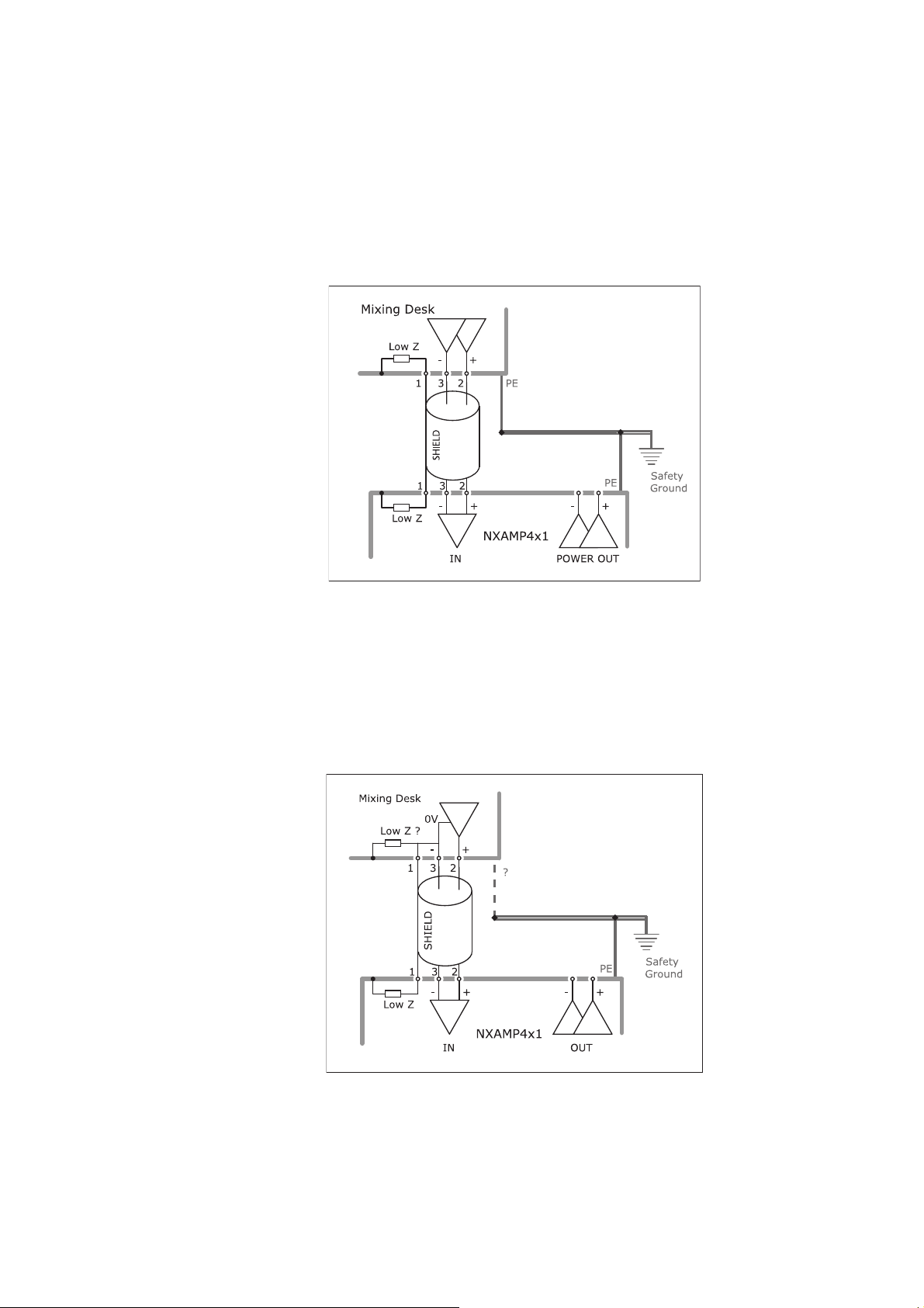
SETTING-UP ADVICE
TDcontroller can sustain high current in pin 1 without degradation of output noise. We
recommend that the sources and loads you use have the same desirable characteristics.
It is sometimes claimed that connecting cable shield at both ends creates ground loops,
and that the current flowing in such loops will produce noise. This is not the case for most
professional audio equipment. In short, there are two kinds of loops in which voltages are
present: the loops formed by signal wires, and the loops formed by grounded conductors,
among which are protective earth conductors (PE) and signal cable shields.
When a cable shield is grounded at both ends, a loop is closed, and the resulting current
causes a reduction of the voltage induced on signal lines. This effect is what the cable
shield is intended to produce, since this is how it protects your signal from magnetic fields.
If you are using an asymmetrical (unbalanced) source (not recommended), it is best to use
a shielded twisted pair and to connect wire 3 of the cable to the shield at the source output
end (see figure bellow).
This technique prevents noise currents flowing on the return path of the signal. (Note that
this is only acceptable for a short cable).
PAGE 27 OF 140

NXAMP power outputs wiring
NEXO recommends the exclusive use of multi-conductor cables to connect the system: the
cable kit is compatible with all the cabinets, and there is no possible confusion between LF,
MF and HF sections.
Cable choice consists mainly of selecting cables of the correct sectional dimension (size) in
relation to the load resistance and the cable length. Too small a cable section will increase
both its serial resistance and its capacitance; this reduces the electrical power delivered to
the loudspeaker and can also induce response (damping factor) variations.
For a serial resistance less or equal to 4% of the load impedance (damping factor = 25),
the maximum cable length is given by:
SETTING-UP ADVICE
= Z x S S in mm2, Z in Ohm, L
L
max
in meters
max
The table below indicates these values, for 3 common sizes.
Load Impedance (Ω)
Cable section Maximum Length (meters)
1,5 mm² (AWG #14) 3 4.5 6 9 12 18 24
2,5 mm² (AWG #12) 5 7.5 10 15 20 30 40
4 mm² (AWG #10) 8 12 16 24 32 48 64
2 3 4 6 8 12 16
PAGE 28 OF 140
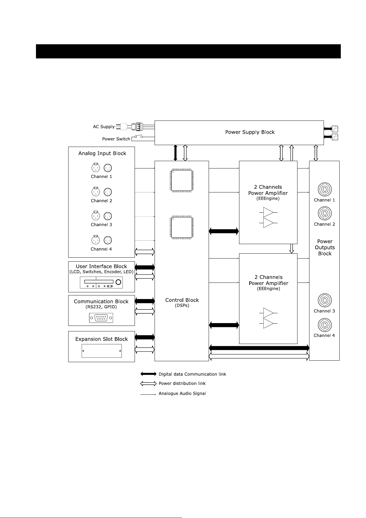
GENERAL DESCRIPTION
Global architecture
NXAMP4x1 Global architecture
The diagram bellow shows the global architecture of the NXAMP4x1 amplifier.
GENERAL DESCRIPTION
NXAMP4x4 Global architecture
The diagram bellow shows the global architecture of the NXAMP4x4 amplifier.
PAGE 29 OF 140
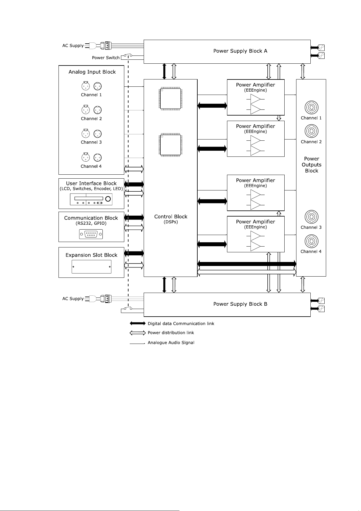
GENERAL DESCRIPTION
Power Supply Block
Power Supply is certainly the most important part of an amplifier. Most of the time, the
Power supply is limiting the power of an amplifier, more than the amplifying circuit itself.
• On NXAMP4x1, two large power supplies are used, one for channel (1 and 2) and
the other for channel (3 and 4).
• On NXAMP4x4, four large power supplies are used, one for each channel.
PAGE 30 OF 140
 Loading...