


NEXCOM International Co., Ltd.
Industrial Computing Solutions
Fanless Computer
NISE 3500, NISE 3500M Series
User Manual
NEXCOM International Co., Ltd.
Published December 2011
www.nexcom.com

Contents
Contents
Preface
Copyright ............................................................................................. iv
Disclaimer ............................................................................................. iv
Acknowledgements .............................................................................. iv
Regulatory Compliance Statements ....................................................... iv
Declaration of Conformity ...................................................................... iv
RoHS Compliance ................................................................................... v
Warranty and RMA ................................................................................ vi
Safety Information ................................................................................vii
Installation Recommendations ................................................................vii
Safety Precautions .................................................................................viii
Technical Support and Assistance ........................................................... ix
Conventions Used in this Manual ........................................................... ix
Global Service Contact Information ......................................................... x
Package Contents ..................................................................................xii
Ordering Information ............................................................................xiii
Chapter 1: Product Introduction
Overview ................................................................................................1
NISE 3500 ..........................................................................................1
NISE 3500M ....................................................................................... 2
Hardware Specifications ..........................................................................3
Getting to Know NISE 3500 Series ..........................................................5
Front Panel of NISE 3500 ....................................................................5
Front Panel of NISE 3500M .................................................................5
Rear Panel of NISE 3500/3500M ......................................................... 6
Mechanical Dimensions ...........................................................................7
NISE 3500/3500M .............................................................................. 7
Chapter 2: Jumpers And Connectors
Before You Begin ....................................................................................8
Precautions .............................................................................................8
Jumper Settings ......................................................................................9
Locations of the Jumpers and Connectors ............................................. 10
NISB 3500 ........................................................................................ 10
Jumpers ................................................................................................ 12
Clear CMOS ..................................................................................... 12
Connectors Pin Definitions .................................................................... 13
External I/O Interface - Front Panel .................................................... 13
USB Ports ..................................................................................... 13
eSATA Ports .................................................................................13
IEEE1394b Connector (NISE 3500M only) ..................................... 14
HDMI Connector (NISE 3500M only) ............................................14
Status Indicators ..........................................................................15
LAN1/LAN2 Link/Active LED .........................................................15
ATX Power On/Off Switch ............................................................ 16
External I/O Interface - Rear Panel ..................................................... 17
Remote Power On/Off Switch ......................................................17
PS/2 Keyboard/Mouse Port ...........................................................17
9V-30V DC Input .........................................................................18
GPIO Connector ..........................................................................18
Copyright © 2011 NEXCOM International Co., Ltd. All Rights Reserved.
ii
NISE 3500, NISE 3500M User Manual

Contents
Serial Interface (COM 1 - COM 4) ................................................19
LAN Ports ....................................................................................21
USB Ports ..................................................................................... 22
VGA Port ..................................................................................... 22
DVI-I Port ..................................................................................... 23
Speaker-out Jack ..........................................................................23
Mic-in Jack ..................................................................................24
Internal Connectors .......................................................................... 25
ATX Power Output Connector ......................................................25
Reset Connector .......................................................................... 25
SMBus DATA/CLK Pin Header .......................................................26
LVDS Backlight Power Select ........................................................26
LVDS Channel A Connector .........................................................27
LVDS Channel B Connector .......................................................... 27
LVDS Backlight Connector ............................................................28
SATA Ports ...................................................................................29
SATA Power Connectors ..............................................................29
SATA DOM Power Connectors .....................................................30
USB Port Connector ..................................................................... 30
COM4 RI Pin Header .................................................................... 31
GPIO LED Connector .................................................................... 31
Line-in Connector ........................................................................ 32
Internal Power/HDD/LAN Power/LAN Active LED ..........................32
Smart Fan Connectors..................................................................33
COM5 Connector ........................................................................ 33
Parallel Connector .......................................................................34
Chapter 3: System Setup
Removing the Chassis Cover ................................................................35
Installing a DIMM ..................................................................................36
Installing the CPU .................................................................................38
Installing a SATA Hard Drive ..................................................................41
Installing a Half Length SATA DOM with SATA HD (NISE
3500P2/3500M2/3500M2 E) .................................................................44
Installing a Full Length SATA DOM ........................................................46
Wallmount Brackets ..............................................................................48
Chapter 4: BIOS Setup
About BIOS Setup ................................................................................. 49
When to Configure the BIOS .................................................................49
Default Configuration ........................................................................... 50
Entering Setup ...................................................................................... 50
Legends ................................................................................................ 50
BIOS Setup Utility .................................................................................. 51
Chapter 5: AMT Settings
Enable Intel® AMT in the AMI BIOS .......................................................64
Configure the Intel
Unconfigure AMT/ME ...........................................................................83
®
ME Setup ..............................................................65
Appendix A: Power Consumption......................... 85
Appendix B: GPI/O Programming Guide...............
87
Appendix C: Watchdog Timer Setting................... 88
Appendix D: Intel Embedded AMT Management
Express KVM......................................
90
Appendix E: Intel Manageability Command Tool -
KVM.................................................... 97
Appendix F: External Anti-vibration Kit................ 103
Appendix G: NISE3500iP2 Series with Isolated DC
Input Design......................................
107
Copyright © 2011 NEXCOM International Co., Ltd. All Rights Reserved.
iii
NISE 3500, NISE 3500M User Manual

Preface
PrefaCe
Copyright
This publication, including all photographs, illustrations and software, is
protected under international copyright laws, with all rights reserved. No
part of this manual may be reproduced, copied, translated or transmitted
in any form or by any means without the prior written consent from
NEXCOM International Co., Ltd.
Disclaimer
The information in this document is subject to change without prior notice
and does not represent commitment from NEXCOM International Co., Ltd.
However, users may update their knowledge of any product in use by constantly checking its manual posted on our website: http://www.nexcom.
com. NEXCOM shall not be liable for direct, indirect, special, incidental, or
consequential damages arising out of the use of any product, nor for any
infringements upon the rights of third parties, which may result from such
use. Any implied warranties of merchantability or fitness for any particular
purpose is also disclaimed.
Acknowledgements
NISE 3500/3500M is a trademark of NEXCOM International Co., Ltd. All
other product names mentioned herein are registered trademarks of their
respective owners.
Regulatory Compliance Statements
This section provides the FCC compliance statement for Class B devices
and describes how to keep the system CE compliant.
Declaration of Conformity
FCC
This equipment has been tested and verified to comply with the limits for
a Class B digital device, pursuant to Part 15 of FCC Rules. These limits are
designed to provide reasonable protection against harmful interference
when the equipment is operated in a commercial environment. This equipment generates, uses, and can radiate radio frequency energy and, if not
installed and used in accordance with the instructions, may cause harmful
interference to radio communications. Operation of this equipment in a
residential area (domestic environment) is likely to cause harmful interference, in which case the user will be required to correct the interference
(take adequate measures) at their own expense.
CE
The product(s) described in this manual complies with all applicable European Union (CE) directives if it has a CE marking. For computer systems to
remain CE compliant, only CE-compliant parts may be used. Maintaining
CE compliance also requires proper cable and cabling techniques.
Copyright © 2011 NEXCOM International Co., Ltd. All Rights Reserved.
iv
NISE 3500, NISE 3500M User Manual

Preface
RoHS Compliance
NEXCOM RoHS Environmental Policy and Status
Update
NEXCOM is a global citizen for building the digital
infrastructure. We are committed to providing green
products and services, which are compliant with European Union RoHS (Restriction on Use of Hazardous Substance in Electronic
Equipment) directive 2002/95/EU, to be your trusted green partner and to
protect our environment.
RoHS restricts the use of Lead (Pb) < 0.1% or 1,000ppm, Mercury (Hg)
< 0.1% or 1,000ppm, Cadmium (Cd) < 0.01% or 100ppm, Hexavalent
Chromium (Cr6+) < 0.1% or 1,000ppm, Polybrominated biphenyls (PBB)
< 0.1% or 1,000ppm, and Polybrominated diphenyl Ethers (PBDE) < 0.1%
or 1,000ppm.
In order to meet the RoHS compliant directives, NEXCOM has established
an engineering and manufacturing task force in to implement the introduction of green products. The task force will ensure that we follow the
standard NEXCOM development procedure and that all the new RoHS
components and new manufacturing processes maintain the highest
industry quality levels for which NEXCOM are renowned.
The model selection criteria will be based on market demand. Vendors and
suppliers will ensure that all designed components will be RoHS compliant.
How to recognize NEXCOM RoHS Products?
For existing products where there are non-RoHS and RoHS versions, the
suffix “(LF)” will be added to the compliant product name.
All new product models launched after January 2006 will be RoHS compliant. They will use the usual NEXCOM naming convention.
Copyright © 2011 NEXCOM International Co., Ltd. All Rights Reserved.
v
NISE 3500, NISE 3500M User Manual

Preface
Warranty and RMA
NEXCOM Warranty Period
NEXCOM manufactures products that are new or equivalent to new in
accordance with industry standard. NEXCOM warrants that products will
be free from defect in material and workmanship for 2 years, beginning
on the date of invoice by NEXCOM. HCP series products (Blade Server)
which are manufactured by NEXCOM are covered by a three year warranty
period.
NEXCOM Return Merchandise Authorization (RMA)
? Customers shall enclose the “NEXCOM RMA Service Form” with the
returned packages.
? Customers must collect all the information about the problems encoun-
tered and note anything abnormal or, print out any on-screen messages,
and describe the problems on the “NEXCOM RMA Service Form” for
the RMA number apply process.
? Customers can send back the faulty products with or without acces-
sories (manuals, cable, etc.) and any components from the card, such as
CPU and RAM. If the components were suspected as part of the problems, please note clearly which components are included. Otherwise,
NEXCOM is not responsible for the devices/parts.
? Customers are responsible for the safe packaging of defective products,
making sure it is durable enough to be resistant against further damage
and deterioration during transportation. In case of damages occurred
during transportation, the repair is treated as “Out of Warranty.”
? Any products returned by NEXCOM to other locations besides the cus-
tomers’ site will bear an extra charge and will be billed to the customer.
Repair Service Charges for Out-of-Warranty Products
NEXCOM will charge for out-of-warranty products in two categories, one
is basic diagnostic fee and another is component (product) fee.
System Level
? Component fee: NEXCOM will only charge for main components such
as SMD chip, BGA chip, etc. Passive components will be repaired for
free, ex: resistor, capacitor.
? Items will be replaced with NEXCOM products if the original one cannot
be repaired. Ex: motherboard, power supply, etc.
? Replace with 3rd party products if needed.
? If RMA goods can not be repaired, NEXCOM will return it to the cus-
tomer without any charge.
Board Level
? Component fee: NEXCOM will only charge for main components, such
as SMD chip, BGA chip, etc. Passive components will be repaired for
free, ex: resistors, capacitors.
? If RMA goods can not be repaired, NEXCOM will return it to the cus-
tomer without any charge.
Copyright © 2011 NEXCOM International Co., Ltd. All Rights Reserved.
vi
NISE 3500, NISE 3500M User Manual

Preface
Warnings
Read and adhere to all warnings, cautions, and notices in this guide and
the documentation supplied with the chassis, power supply, and accessory
modules. If the instructions for the chassis and power supply are inconsistent with these instructions or the instructions for accessory modules,
contact the supplier to find out how you can ensure that your computer
meets safety and regulatory requirements.
Cautions
Electrostatic discharge (ESD) can damage system components. Do the described procedures only at an ESD workstation. If no such station is available, you can provide some ESD protection by wearing an antistatic wrist
strap and attaching it to a metal part of the computer chassis.
Safety Information
Before installing and using the device, note the following precautions:
▪ Read all instructions carefully.
▪ Do not place the unit on an unstable surface, cart, or stand.
▪ Follow all warnings and cautions in this manual.
▪ When replacing parts, ensure that your service technician uses parts
specified by the manufacturer.
▪ Avoid using the system near water, in direct sunlight, or near a heating
device.
▪ The load of the system unit does not solely rely for support from the
rackmounts located on the sides. Firm support from the bottom is highly
necessary in order to provide balance stability.
▪ The computer is provided with a battery-powered real-time clock circuit.
There is a danger of explosion if battery is incorrectly replaced. Replace
only with the same or equivalent type recommended by the manufactur-
er. Discard used batteries according to the manufacturer’s instructions.
Installation Recommendations
Ensure you have a stable, clean working environment. Dust and dirt can
get into components and cause a malfunction. Use containers to keep
small components separated.
Adequate lighting and proper tools can prevent you from accidentally
damaging the internal components. Most of the procedures that follow
require only a few simple tools, including the following:
• A Philips screwdriver
• A flat-tipped screwdriver
• A grounding strap
• An anti-static pad
Using your fingers can disconnect most of the connections. It is recommended that you do not use needlenose pliers to disconnect connections
as these can damage the soft metal or plastic parts of the connectors.
Copyright © 2011 NEXCOM International Co., Ltd. All Rights Reserved.
vii
NISE 3500, NISE 3500M User Manual

Preface
Safety Precautions
1. Read these safety instructions carefully.
2. Keep this User Manual for later reference.
3. Disconnect this equipment from any AC outlet before cleaning. Use a
damp cloth. Do not use liquid or spray detergents for cleaning.
4. For plug-in equipment, the power outlet socket must be located near
the equipment and must be easily accessible.
5. Keep this equipment away from humidity.
6. Put this equipment on a stable surface during installation. Dropping
it or letting it fall may cause damage.
7. Do not leave this equipment in either an unconditioned environment
or in a above 40
equipment.
8. The openings on the enclosure are for air convection to protect the
equipment from overheating. DO NOT COVER THE OPENINGS.
9. Make sure the voltage of the power source is correct before connect-
ing the equipment to the power outlet.
10. Place the power cord in a way so that people will not step on it. Do
not place anything on top of the power cord. Use a power cord that
has been approved for use with the product and that it matches the
voltage and current marked on the product’s electrical range label.
The voltage and current rating of the cord must be greater than the
voltage and current rating marked on the product.
11. All cautions and warnings on the equipment should be noted.
o
C storage temperature as this may damage the
12. If the equipment is not used for a long time, disconnect it from the
power source to avoid damage by transient overvoltage.
13. Never pour any liquid into an opening. This may cause fire or electrical shock.
14. Never open the equipment. For safety reasons, the equipment should
be opened only by qualified service personnel.
15. If one of the following situations arises, get the equipment checked
by service personnel:
a. The power cord or plug is damaged.
b. Liquid has penetrated into the equipment.
c. The equipment has been exposed to moisture.
d. The equipment does not work well, or you cannot get it to work
according to the user’s manual.
e. The equipment has been dropped and damaged.
f. The equipment has obvious signs of breakage.
16. Do not place heavy objects on the equipment.
17. The unit uses a three-wire ground cable which is equipped with a
third pin to ground the unit and prevent electric shock. Do not defeat
the purpose of this pin. If your outlet does not support this kind of
plug, contact your electrician to replace your obsolete outlet.
18. CAUTION: DANGER OF EXPLOSION IF BATTERY IS INCORRECTLY
REPLACED. REPLACE ONLY WITH THE SAME OR EQUIVALENT TYPE
RECOMMENDED BY THE MANUFACTURER. DISCARD USED BATTERIES ACCORDING TO THE MANUFACTURER’S INSTRUCTIONS.
19. The computer is provided with CD drives that comply with the appropriate safety standards including IEC 60825.
Copyright © 2011 NEXCOM International Co., Ltd. All Rights Reserved.
viii
NISE 3500, NISE 3500M User Manual

Preface
CAUTION!
Technical Support and Assistance
1. For the most updated information of NEXCOM products, visit NEXCOM’s website at www.nexcom.com.
2. For technical issues that require contacting our technical support team
or sales representative, please have the following information ready
before calling:
– Product name and serial number
– Detailed information of the peripheral devices
– Detailed information of the installed software (operating system,
version, application software, etc.)
– A complete description of the problem
– The exact wordings of the error messages
Warning!
1. Handling the unit: carry the unit with both hands and handle it with
care.
2. Maintenance: to keep the unit clean, use only approved cleaning products or clean with a dry cloth.
3. CompactFlash: Turn off the unit’s power before inserting or removing a
CompactFlash storage card.
Conventions Used in this Manual
Warning: Information about certain situations, which if not
observed, can cause personal injury. This will prevent injury to
yourself when performing a task.
CAUTION!CAUTION!
Caution: Information to avoid damaging components or losing
data.
Note: Provides additional information to complete a task easily.
Safety Warning: This equipment is intended for installation in a
Restricted Access Location only.
Copyright © 2011 NEXCOM International Co., Ltd. All Rights Reserved.
ix
NISE 3500, NISE 3500M User Manual

Preface
Global Service Contact Information
Headquarters
Taiwan
15F, No.920,Chung-Cheng Road, Zhonghe Dist.
New Taipei City, Taiwan 23586, R.O.C.
Tel: +886-2-8226-7786
Fax: +886-2-8226-7782
http://www.nexcom.com.tw
USA
3758 Spinnaker Court,
Fremont, CA 94538, USA
Tel: +1-510-656-2248
Fax: +1-510-656-2158
http://www.nexcom.com
France
Z.I. des Amandiers, 17, Rue des entrepreneurs
78420 Carrières sur Seine, France
Tel: +33 (0)1 71 51 10 20
Fax: +33 (0)1 71 51 10 21
http://www.nexcom.eu
Germany
Leopoldstrase Business Centre, Leopoldstrase 244 80807
Munich, Germany
Tel: +49-89-208039-278
Fax: +49-89-208039-279
http://www.nexcom.eu
Italy
Via Gaudenzio Ferrari 29, 21047 Saronno (VA) Italia
Tel: +39 02 9628 0333
Fax: +39 02 9619 8846
http://www.nexcom.eu
United Kingdom
10 Vincent Avenue, Crownhill Business Centre
Milton Keynes, Buckinghamshire, MK8 0AB
United Kingdom
Tel: +44-1908-267121
Fax: +44-1908-262042
http://www.nexcom.eu
Copyright © 2011 NEXCOM International Co., Ltd. All Rights Reserved.
x
NISE 3500, NISE 3500M User Manual

Preface
China-Beijing
Room 301, Block E, Power Creative Building, No. 1
Shangdi East Rd. Haidian Dist., Beijing, 100085, China
Tel: +86-10-5885-6655
Fax: +86-10-5885-1066
http://www.nexcom.cn
China-Shanghai Office
Room 1505, Greenland He Chuang Building, No. 450
Caoyang Rd. Shanghai, 200063, China
Tel: +86-21-6150-8008
Fax: +86-21-3251-6358
http://www.nexcom.cn
China-Nanjing Office
Room 1206, Hongde Building, No. 20 Yunnan Rd.
Nanjing, 210018, China
Tel: +86-25-8324-9606
Fax: +86-25-8324-9685
http://www.nexcom.cn
China-Shenzhen Office
Western Room 708, Block 210, Tairan Industry & Trading Place,
Futian Area, Shenzhen, China 518040
TEL: +86-755-833 27203
FAX: +86-755-833 27213
http://www.nexcom.cn
Japan
9F, Tamachi Hara Bldg.,
4-11-5, Shiba Minato-ku Tokyo,
Japan 108-0014
Tel: +81-3-5419-7830
Fax: +81-3-5419-7832
http://www.nexcom-jp.com
Copyright © 2011 NEXCOM International Co., Ltd. All Rights Reserved.
xi
NISE 3500, NISE 3500M User Manual

Preface
PaCkage Contents
Before continuing, verify that the NISE 3500 Series package that you received is complete. Your package should have all the items listed in the following
table.
Item Part Number Description Qty
1 60233POW33X00 DC Power Cable 1
2 6023344361X00 DB44 to 4x DB9 COM port cable 1
3 6029900037X00 DOW CORNING 340 Silcone Heat Sink Compound(3g) 1
4 4NCPM00203X00 2 Pin Phoenix Contact: MC 1.5/2-ST-3.81(1803578), 3.81mm pitch 1
5 50311F0110X00 Flat Head Screw for HDD F3x5 ISO+NYLOK NIGP 4
6 602DCD0269X00 NISB3500 CD DRIVER VER:1.0 1
7 7800000014X00 DVI-I TO VGA Adapter 1
8 5060600087X00 Mylar for PCI bracket 1
9 60177A0205X00 NISB3500 Quick Reference Guide VER:A 1
10 50311P0001X00 Plastic Screw for PCI card use 1
11 60233MK202X00 PS/2 Y Cable for Keyboard / Mouse, L:150mm 1
12 50322P0001X00 Plastic Nut for PCI card use 1
Copyright © 2011 NEXCOM International Co., Ltd. All Rights Reserved.
xii
NISE 3500, NISE 3500M User Manual

Preface
ordering information
The following provides ordering information for NISE 3500 Series.
• Barebone
NISE 3500M (P/N: 10J00350001X0) RoHS Compliant
- Intel
- 1 x PCI expansion slot
NISE 3500 (P/N: 10J00350000X0) RoHS Compliant
- Intel
- 1 x PCI expansion slot
NISE 3500P2 (P/N: 10J00350002X0) RoHS Compliant
- Intel
- 2 x PCI expansion slots
NISE 3500M2 E (P/N: 10J00350003X0) RoHS Compliant
- Intel
- 1 x PCI expansion slot, 1 x PCIe expansion slot
• 19V, 120W AC/DC Power Adapter w/o power cord
(P/N: 7410120002X00)
®
Core™ i7/i5 Fanless System
®
Core™ i7/i5 Fanless System
®
Core™ i7/i5 Fanless System
®
Core™ i7/i5 Fanless System
Copyright © 2011 NEXCOM International Co., Ltd. All Rights Reserved.
xiii
NISE 3500, NISE 3500M User Manual
Chapter 1: Product Introduction
ChaPter 1: ProduCt introduCtion
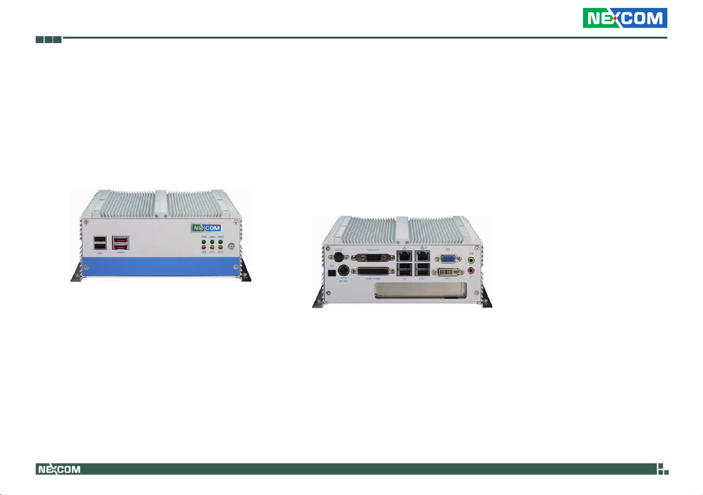
Overview
NISE 3500
Front
Key Features
®
• Intel
• Mobile Intel
• Dual Intel
Core™ i7/i5 socket processor
®
QM57 PCH
®
Gigabit Ethernet ports
• Dual VGA or VGA/DVI Independent Display
• 3x RS232 and 1x RS232/422/485 with Auto Flow
Control
Copyright © 2011 NEXCOM International Co., Ltd. All Rights Reserved.
Rear
• 4 x Digital Input, 4 x Digital Output
• Onboard DC to DC power design to support
9V to 30V DC power input
• Supports ATX power mode and PXE/WOL
1
NISE 3500, NISE 3500M User Manual

Chapter 1: Product Introduction
NISE 3500M
Key Features
®
• Intel
• Mobile Intel
• Dual Intel
• Dual VGA or VGA/DVI or DVI/HDMI Independent
• 3x RS232 and 1x RS232/422/485 with Auto Flow
Core™ i7/i5 socket processor
®
Display
Control
Front
®
QM57 PCH
Gigabit Ethernet ports
Rear
• 3x IEEE1394b ports, 2x eSATA
• Onboard DC to DC power design to support 9V to 30V
DC power input
• Supports ATX power mode and PXE/WOL
Copyright © 2011 NEXCOM International Co., Ltd. All Rights Reserved.
2
NISE 3500, NISE 3500M User Manual

Chapter 1: Product Introduction
Hardware Specifications
Main Board
• NISB 3500
• Onboard Mobile Intel
• Supports Intel
• Supports Intel
• Supports Intel
®
®
®
Main Memory
• 2x 240-pin memory DIMM, up to 4GB DDR3 800/1066MHz SDRAM,
unbuffered and non-ECC
Note: The actual memory size is dynamic. It is based on the OS I/O re-
source allocation.
I/O Interface - Front
• ATX power on/off switch
• HDD Access / Power status LEDs
• 2 x USB2.0 ports
• 2 x eSATA ports
• 3 x IEEE1394b ports (NISE 3500M only)
• 1 x HDMI port (NISE 3500M only)
®
QM57 Platform Controller Hub
Core™ i7-620M PGA Processor (2.66GHz, 4M Cache)
Core™ i5-520M PGA Processor (2.4GHz, 3M Cache)
P4500 PGA Processor (1.86GHz, 2M Cache)
I/O Interface - Rear
• 2-pin Remote Power on/off switch
• 9 ~ 30V DC input
• 1 x PS/2 for Keyboard/Mouse
• 1 x DB15 male connector for GPIO (4x digital-input and 4x digital-out-
put)
• 1 x DB44 Serial Port for 4x RS232
(COM2: RS232/422/485 with Auto Flow Control)
• 2 x Gbe LAN ports
• 4 x USB2.0 ports
• 1 x DB15 VGA port
• 1 x DVI-I Port
• 1 x Speaker-out
• 1 x Mic-in
Device
• 1 x 2.5” HDD drive bay
Expansion
• One PCI expansion
• Max. Supported Add-on Card Length: 169mm
Copyright © 2011 NEXCOM International Co., Ltd. All Rights Reserved.
3
NISE 3500, NISE 3500M User Manual

Chapter 1: Product Introduction
Power Requirements
• ATX power mode
• Onboard DC to DC power support from 9V to 30V DC
• Optional power adapter
Dimensions
• 195mm (W) x 268mm (D) x 80mm (H) (7.7” x 10.5” x 3.1”)
Construction
• Aluminum chassis with fanless design
Environment
• Operating temperature:
Ambient with airflow: -5°C to 55°C
(According to IEC60068-2-1, IEC60068-2-2, IEC60068-2-14)
• Storage temperature: -20°C to 80°C
• Relative humidity: 10% to 93% (Non-Condensing)
Certifications
• CE approval
• FCC Class A
Copyright © 2011 NEXCOM International Co., Ltd. All Rights Reserved.
4
NISE 3500, NISE 3500M User Manual

Chapter 1: Product Introduction
Getting to Know NISE 3500 Series
Front Panel of NISE 3500
LAN LEDs
Power LED
eS ATA
USB
USB
Used to connect USB 2.0/1.1 devices.
eSATA
Used to connect eSATA devices.
IEEE1394b
Used to connect IEEE1394b devices.
HDMI
Used to connect devices that support HDMI.
HDD LED
Power on/off
switch
Front Panel of NISE 3500M
LAN LEDs
Power LED
USB eSATA 1394b
Power LED
Indicates the power status of the system.
HDD LED
Indicates the status of the hard drive.
LAN LEDs
Indicate the status of the LAN ports.
Power On/Off Switch
Press to power-on or power-off the system.
HDD LED
HDMI
Power on/off
switch
Copyright © 2011 NEXCOM International Co., Ltd. All Rights Reserved.
5
NISE 3500, NISE 3500M User Manual

Chapter 1: Product Introduction
Rear Panel of NISE 3500/3500M
GPIO
PS/2 KB/Mouse
Output for
remote power
on/off swtich
COM1-COM4
9V-30V
DC Input
Output for Remote Power On/Off Switch
Used to connect a remote to power on/off the system.
PS/2 Keyboard/Mouse
Used to connect a PS/2 keyboard and PS/2 mouse via a cable.
9V-30V DC Input
Used to plug a DC power cord.
GPIO
The GPIO connector supports 4 digital input and 4 digital output.
COM1 to COM4
The DB44 port supports 3 RS232 and 1 RS232/422/485 compatible serial
devices.
LAN
USB
VGA
Speaker-out
1 expansion
card slot
LAN
Used to connect the system to a local area network.
USB
Used to connect USB 2.0/1.1 devices.
VGA
Used to connect an analog VGA monitor.
DVI
Used to connect a digital LCD panel.
Speaker-out
Used to connect a headphone or a speaker.
Mic-in
Used to connect an external microphone.
Expansion Slot
One PCI expansion slot.
Copyright © 2011 NEXCOM International Co., Ltd. All Rights Reserved.
6
NISE 3500, NISE 3500M User Manual

Chapter 1: Product Introduction
Mechanical Dimensions
NISE 3500/3500M
184.00
224.00
264.00
268.00
195.00
207.00
219.00
Copyright © 2011 NEXCOM International Co., Ltd. All Rights Reserved.
86.00
80.00
7
NISE 3500, NISE 3500M User Manual

ChaPter 2: JumPers and ConneCtors
This chapter describes how to set the jumpers on the motherboard. Note
that the following procedures are generic for all NISE 3500 series.
Before You Begin
• Ensure you have a stable, clean working environment. Dust and dirt can
get into components and cause a malfunction. Use containers to keep
small components separated.
• Adequate lighting and proper tools can prevent you from accidentally
damaging the internal components. Most of the procedures that follow
require only a few simple tools, including the following:
• A Philips screwdriver
• A flat-tipped screwdriver
• A set of jewelers Screwdrivers
• A grounding strap
• An anti-static pad
• Using your fingers can disconnect most of the connections. It is recom-
mended that you do not use needle-nosed pliers to disconnect connections as these can damage the soft metal or plastic parts of the connectors.
• Before working on internal components, make sure that the power
is off. Ground yourself before touching any internal components, by
touching a metal object. Static electricity can damage many of the elec-
tronic components. Humid environment tend to have less static electricity than dry environments. A grounding strap is warranted whenever
danger of static electricity exists.
Precautions
Computer components and electronic circuit boards can be damaged by
discharges of static electricity. Working on the computers that are still connected to a power supply can be extremely dangerous.
Follow the guidelines below to avoid damage to your computer or yourself:
• Always disconnect the unit from the power outlet whenever you are
working inside the case.
• If possible, wear a grounded wrist strap when you are working inside
the computer case. Alternatively, discharge any static electricity by
touching the bare metal chassis of the unit case, or the bare metal body
of any other grounded appliance.
• Hold electronic circuit boards by the edges only. Do not touch the com-
ponents on the board unless it is necessary to do so. Don’t flex or stress
the circuit board.
• Leave all components inside the static-proof packaging that they
shipped with until they are ready for installation.
• Use correct screws and do not over tighten screws.
Copyright © 2011 NEXCOM International Co., Ltd. All Rights Reserved.
8
NISE 3500, NISE 3500M User Manual

Jumper Settings
A jumper is the simplest kind of electric switch. It consists of two metal
pins and a cap. When setting the jumpers, ensure that the jumper caps are
placed on the correct pins. When the jumper cap is placed on both pins,
the jumper is short. If you remove the jumper cap, or place the jumper
cap on just one pin, the jumper is open.
Refer to the illustrations below for examples of what the 2-pin and 3-pin
jumpers look like when they are short (on) and open (off).
Two-Pin Jumpers: Open (Left) and Short (Right)
Three-Pin Jumpers: Pins 1 and 2 Are Short
Copyright © 2011 NEXCOM International Co., Ltd. All Rights Reserved.
9
NISE 3500, NISE 3500M User Manual

Locations of the Jumpers and Connectors
CON2
NISB 3500
The figure below is the top view of the NISB 3500 main board which is the main board used in the NISE 3500 Series system. It shows the locations of the
jumpers and connectors.
CN1
CN2
CN3
CN6
CN9
CN11
J3
1
CON1
J1
J18
J2
SW1
J4
LED1
LED2
LED3
J5
1
J6
JP2
J9
J15
JP1
J8
CN4
CN5
1
J13
JP3
CN7
CN8
DIMM2
J12
DIMM1
J14
BAT1
JP4
J7
J10
J11
CN10
Copyright © 2011 NEXCOM International Co., Ltd. All Rights Reserved.
10
NISE 3500, NISE 3500M User Manual

The figure below is the bottom view of the NISB 3500 main board.
CN16
Copyright © 2011 NEXCOM International Co., Ltd. All Rights Reserved.
CN17
J17
J16
CN12
9
CN15
11
CN13
CN14
NISE 3500, NISE 3500M User Manual

Jumpers
Clear CMOS
Connector size: 1x3 3-pin header, 2.54 mm pitch
Connector location: JP4
1
Pin Settings
1-2 On *Normal
2-3 On CMOS Clear
1-2 On: default
Pin Definition
3
1 RTCRST#_PU
2 RTCRST#
3 CLR_CMOS
Copyright © 2011 NEXCOM International Co., Ltd. All Rights Reserved.
12
NISE 3500, NISE 3500M User Manual

Connector Pin Definitions
External I/O Interface - Front Panel
USB Ports
Connector type: Dual USB port
Connector location: CN10
Pin Definition Pin Definition
1 +5V 7 USB1+
2 USB0- 8 GND
3 USB0+ 22 GND
4 GND 23 GND
5 +5V 26 GND
6 USB1- 27 GND
eSATA Ports
Connector type: eSATA port
Connector location: CON2A and CON2B
Pin Definition Pin Definition
1 GND 5 SATA_RXN4
2 SATA_TXP4 6 SATA_RXP4
3 SATA_TXN4 7 GND
4 GND
Copyright © 2011 NEXCOM International Co., Ltd. All Rights Reserved.
13
NISE 3500, NISE 3500M User Manual

IEEE1394b Connector (NISE 3500M only)
Connector type: 1394
Connector location: J7, J10 and J11
HDMI Connector (NISE 3500M only)
Connector type: HDMI
Connector location: J6
Pin Description Pin Description
1 TB2N 2 TB2P
3 TA2N 4 TA2P
5 1394B_SG_2 6 GND
7 NC 8 +12V
9 GND
19
18
Pin Definition Pin Definition
1 HDMID_D2P 2 GND
3 HDMID_D2N 4 HDMID_D1P
5 GND 6 HDMID_D1N
7 HDMID_D0P 8 GND
9 HDMID_D0N 10 HDMID_LKP
11 GND 12 HDMID_LKN
13 NC 14 NC
15 HDMID_CTL_CLK 16 HDMID_CTL_SDA
17 GND 18 +5V
19 HDP
1
2
Copyright © 2011 NEXCOM International Co., Ltd. All Rights Reserved.
14
NISE 3500, NISE 3500M User Manual

Status Indicators
PWR
LAN1/LAN2 Link/Active LED
Connector location: LED1 and LED2
HDD
Status LED Color
PWR Green
HDD Yellow
LINK1
LINK2
ACT1
ACT2
Pin Definition
C1 LAN2_LINK_N
C2 LAN2_ACT_N
A1 LAN2_LINK_P
A2 LAN2_ACT_P
Copyright © 2011 NEXCOM International Co., Ltd. All Rights Reserved.
15
NISE 3500, NISE 3500M User Manual

ATX Power On/Off Switch
Connector location: SW1
Pin Definition
On Blue light
Off Red light
Pin Definition Pin Definition
1 GND 2 PBT_PU
3 PBT_PU 4 GND
A1 PWRLED_N C1 PWRLED_P
Copyright © 2011 NEXCOM International Co., Ltd. All Rights Reserved.
16
NISE 3500, NISE 3500M User Manual
External I/O Interface - Rear Panel
Connector type: 2-pin switch
Connector location: J3
1 2
Pin Definition
1 GND
2 PBT_PU
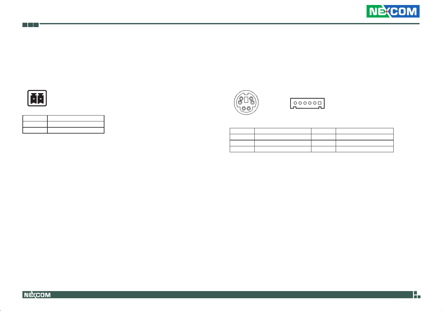
PS/2 Keyboard/Mouse Port
Connector type: PS/2, Mini-DIN-6, JST-2.0mm-M-180
Connector location: J5
6
4
Pin Definition Pin Definition
1 5VSB 2 KDAT
3 KCLK 4 MDAT
5 MCLK 6 GND
5
3
2
1
16
Copyright © 2011 NEXCOM International Co., Ltd. All Rights Reserved.
17
NISE 3500, NISE 3500M User Manual
 Loading...