

Page 1

B
O I
USM 69 i
· . · ·
() / - · - · @. · ..
Page 2

Inhaltsverzeichnis
1. Das Kondensator-Stereomikrofon USM 69 i
2. Richtcharakteristik-Umschaltung
3. Ausführungsformen und Beschaltung des Ausgangs
4. Mikrofonkabel
5. Stromversorgung
6. Betrieb an unsymmetrischen und mittengeerdeten
Eingängen
7. Frequenzgänge und Polardiagramme
8. Technische Daten
9. Einige Hinweise zur Pege von Mikrofonen
10. Zubehör
Table of Contents
1. The USM 69 i Stereo Condenser Microphone
2. Directional Pattern Selection
3. Microphone Versions and Output Wiring
4. Microphone Cables
5. Power Supply
6. Operation with Unbalanced or Center Tap
Grounded Inputs
7. Frequency Response and Polar Patterns
8. Technical Specications
9. Hints on Microphone Maintenance
10. Accessories
1. Das Kondensator-Stereomikrofon
USM69 i
Das Kondensator-Stereomikrofon USM 69 i ist
ein ortsumschaltbares Studiomikrofon der Serie
fet80 für die stereopho ne Aufnahmetechnik. Sein e
akustischen Wandlereigenschaen gleichen denen
des bekannten fernumschaltbaren Stereomikrofons SM69 fet, dessen Kapselauau unveränder t
übernommen wurde.
Wie dieses Mikrofon besteht es aus dem Kapselkopf, in dem zwei getrennte, voneinander unabhängige Mikrofonkapseln mit Membranen aus
goldbedampen Polyesterfolien angeordnet sind,
und dem Verstärkerteil, der zwei voneinander
unabhängige Mikrofonverstärker enthält. Beide
Kapseln sind dicht übereinander angeordnet; das
obere System kann gegenüber dem unteren um
270° verdreht werden. Dadur ch ist es möglich, mit
diesem Mikrofonaufnahmen nach dem Prinzip der
Intensitäts-Stereophonie (MS und XY) zu machen.
Bei derartigen Aufnahmen erzeugen aus verschiedenen Richtungen einwirkende Schallquellen in
beiden Mikrofonkapseln nur Intensitäts-, nicht
aber Laufzeitunterschiede, und es ist möglich,
beide Signale für eine gute Einkanalwiedergabe
zu addieren, ohne da ss es zu Interferenzen komm t.
Die auf dem unteren Kapselsystem angeordneten
Farbpunkte können dabei als Orientierungshilfe für
den Winke l dienen, um den das o bere Kapsels ystem
gegenüber dem unteren verdreht wurde.
1. The USM 69 i Stereo Condenser
Microphone
The USM 69 i stereo condenser microphone is a
fet 80 series studio microphone for high quality
stereo recordings featuring built-in directional pattern selectors. Its acoustical characteristics are
identical to those of the well-known SM 69 fet stereo cond enser micropho ne since the entire capsule
conguration has been adopted from i t unchanged.
As in the SM 69 fet, the microphone head of the
USM 69 i houses two completely separate condenser elements with gold-coated polyester lm
membranes, mounted one above the other and
each associated with two completely separate
microphone preamps. The upper capsule may be
rotated against the lower one through an arc of
270 degrees . This makes intensi ty stereo recor ding
(MS or XY) possible. With this technique sounds
impinging from dierent directions produce only
intensity dierences, yet no delay (phase) dierences between the two systems. As a result, both
signals may be combined to obtain good mono
reproduction without phase cancellation interference. Color marks on the lower capsule grille
indicate the angle between the axes of maximum
sensitivity of the upper and the lower capsule
(pick-up angles).
2
Page 3

USM 69 i
Außer als Stereomikrofon lässt sich das USM 69i
auch überall verwenden, wo an einem Ort zwei
Einkanal-Mikrofone benötigt werden oder wo für
eine Einkanalaufnahme das zweite System al s Reservemikrofon dienen soll.
Beide Mikrofonsysteme arbeiten unabhängig voneinander. So gar bei Erdschl uss der Speise spannung
in einem der Kanäle oder beim Kurzschluss eines
Ausgangs arbeitet der zweite Mikrofonverstärker
ungestört weiter.
Die Verstärker des USM 69 i sind trotz besonders
geringen Eigenrauschens sehr weit aussteuerbar.
Daher sind Aufnahmen sehr lauter Schallquellen
in größerem Abst and wie auch im Nahbereich problemlos möglich.
Jeder Verstärker enthält ein aktives Filter, das unterhörfrequente Spannungen, wie sie durch Trittschall oder Wind entstehen können, sperrt und
zugleich verhindert, dass die Ausgangstransformatoren durch diese – sonst unhörbaren – Schallanteile übersteuert werden.
Durch verschiedene Maßnahmen wurde dieses
Mikrofon außer gegen parasitäre Wechselströme im Kabelschirm (sogenannte Brummschleifen
usw.) auch gegen Störungen durch Rundfunk- und
Fernsehsender sowie durch Radargeräte besonders störfest gemacht. Sollten unter extremen
Bedingungen – meist infolge unzweckmäßiger
Verkabelung – dennoch solche Störungen aureten,
fordern Sie bitte uns er Informationsblatt 8 3218 an.
In addition, the USM 69 i may be used to drive
mono channels where two independent microphones or a back-up system are needed at the
same location.
Both microphone systems are electrically independent of one another. The other micr ophone preamp
will not be aected, even with an earth (ground)
fault of the supply voltage in one channel or shorting of one output.
The preampliers of the USM 69 i are designed
as operational ampliers oerin g additional headroom and particularly low equivalent noise. The
USM 69 i therefore picks up both distant sound
sources as well as extremely loud sound sources
at close proximity without diculty.
Both preamps are equipped with an active lter
blocking subaudio sound (as may be caused by
mechanical shock or wind) ahead of the output
transformers preventing the latter from being
overloaded.
Several design features render this microphone
largely immune not only to parasitic alternating
currents in the cable shield, so-called ac-induced
hum, but also to inter ference caused by radio and
TV transmitter s as well as radar equipment. S hould
however such interferences happen, as e. g. caused
by inadequate wiring, please ask for our information 83218.
2. Richtcharakteristik-Umschaltung
Im Gegensatz zum SM 69 fet wird die Richtcharakteristik beider Kapseln mittels zweier Drehschalter
im Mikrofon selbst umgeschaltet. Das Mikrofon
benötigt daher kein spezielles Netz- oder sonstiges
Anschlussgerät, sondern seine beiden Ausgänge
können direkt auf alle für die P48-Phantomspeisung ausgelegten Anschlüsse geschaltet werden.
Außer den drei üblichen Richtcharakteristiken –
Kugel, Niere, Acht – kann jede Kapsel auch auf die
Zwischenstellungen „Hyperniere” und „breite Niere” geschaltet werden.
Die erforderlichen Kapselvorspannungen erzeugt
ein eingebauter Gleichspannungswandler. Er arbeitet auch dann zuverlässig, wenn nur eines der
beiden Systeme betrieben und angeschlossen wird.
Obwohl dank seiner einfachen und betriebssicheren
2. Directional Pattern Selection
By contrast to the SM 69 fet the USM 69 i features
two ush-mounted rotary directional pattern selectors. Therefore, no special ac power supply unit
or power ing adapters are ne eded. The two outputs
of the USM 69 i connect directly to any 48-voltphantom powered outlets.
Besides the three usual ones – omni, cardioid,
gure-8 – the intermediate polar patterns wideangle cardioid and hypercardioid are selectable.
A built-in dc converter generate s the required cap sule bias voltages. It s reliable operation is ensured
even if only one of the two microphone systems
is being used. Its simple and largely fail-safe circuitry assures a low failure rate, but should the
dc converter ever fail, a special diode circuit in
the micro phone ensures that both capsule systems
3
Page 4

Schaltung Ausfälle nicht zu befürchten sind, stellt
eine Diodenschaltung im Mikrofo n sicher, dass beide
Systeme auch bei einem Versagen des Gleichspannungswandlers weiterarbeiten. Sie schalten sich
dabei in die Richtcharakteristik „Niere”. Das Übertragungsmaß sinkt um ca. 3 dB.
will keep operating even if only with cardioid directional pattern and a 3 dB reduced sensitivity.
3. Ausführungsformen und Beschaltung
des Ausganges
Das Mikrofon kann in den folgenden Ausführungsformen geliefert werden:
USM 69 i ..............ni ............Best.-Nr. 006974
Standardausführung mit 5-poligem SwitchcraSteckereinsatz und nickelmatter Oberäche. Erforder liches Gege nstück: X LR 5 F.
Die Zuordnung der Mikrofonanschlüsse entspricht
DIN EN 60268-12 bzw. IEC 60268-12.
System I:
Untere, nicht verdrehbare Kapsel, das Firmenschild
kennzeichnet die Hauptempfangsrichtung, gelber
(unterer) Charakterist ikumschalter, Anschluss über
Pin 2 (+) und 3.
System II:
Obere, verdrehbare Kapsel, ein Nippel auf dem
unteren Ring der Kapsel kennzeichnet die Hauptempfangsrichtung, roter (oberer) Charakteristikumschalter, Anschluss über Pin 4 (+) und 5.
Hierbei kennzeichn et (+) die Polar ität bei Druckanstieg vor der Membran. Pin 1: Gehäuse und 0 Volt.
USM 69 i mt .........sw ...........Best.-Nr. 006976
Wie oben, jedoch mit dunkel mattierter Oberäche.
4. Mikrofonkabel
Die höchste zulässige Kabellänge zwischen Mikrofon und Verstärker beträgt etwa 300 m. Bei
größeren Kabellängen beeinusst die Kabelkapazität den Frequenzgang und führt in Verbindung
mit der Streuinduktivität des Mikrofonübertragers
zunächst zu einem Anstieg am oberen Ende des
Übertragungsbereiches.
Für das Mikrofon USM 69 i stehen folgende Kabel
zur Verfügung:
3. Microphone Versions and
Output Wiring
The following versions are provided:
USM 69 i ..............ni .............Cat. No. 006974
Standard version with male 5-pole Switchcra
connector insert and satin nickel nish. Requires
XLR 5 F cabl e co nnector.
The microphone is wired as per DIN EN 60268-12
or IEC 60268-12.
System I:
Lower capsule (not rotable). The axis of maximum
sensitivity is indicated by the Neumann emblem.
Yellow (lower) directional pattern selector. Modulation connects to pins 2 (+) and 3.
System II:
Upper capsule (rotatable). The axis of maximum
sensit ivity is indicated by an emb ossed dot on the
lower rim of the upper capsule cage. Red (upper)
direct ional pattern selector. Modulation connec ts
to pins 4 (+) and 5.
A sudden r ise in sound pres sure in front of the fr ont
membrane causes a positive voltage to appear at
the pins marked (+). Pin 1: 0 V and shield.
USM 69 i mt .........blk ........... Cat. No. 00 6976
As above, but with dark matt nish.
4. Microphone Cables
The cable length between microphone and following preamplier should not exceed 300m (980.).
The capacitance of greater cable lengths could affect the frequency response and, in conjunction
with the leakage inductance of the microphone’s
output transformer, would result in a rise at the
upper end of the frequency range.
The following cables are available for the USM 69 i
microphone:
4
Page 5

USM 69 i
IC 5 (10 m) ...........ni ............Best.-Nr. 006623
IC 5 mt (10 m) ......sw .......... Best.-Nr. 006624
Mikrofonkabel mit Doppeldrallumspinnung als
Abschirmung. Ø 5 mm, Länge 10 m. XLR 5 Steckverbinder, schwarzmatt.
IC 6 (10 m)...........ni ............Best.-Nr. 006621
IC 6 mt (10 m) ......sw ...........Best.-Nr. 006622
Kabel mit dreh- und schwenkbarem Stativgelenk
für Mikrofone mit Gewindeanschluss, mit Doppeldrallumspinnung als Abschirmung. Der Gewindeanschluss hat 5/8"-27-Gang, mit Adapter für
1/2"- und 3/8"-Stative. Ø 5 mm, Länge 10 m.
XLR 5-Verbinder.
AC 20 (1 m) ..........................Best.-Nr. 006595
Y-Kabel mit einer 5-poligen XLR-Buchse und zwei
3-poligen XLR-Steckern, für die Verteilung von
2-kanaliger Modulation auf 2 Monokanäle, z. B . bei
Verwendung des Speisegerätes BS 48 i-2.
Andere Kabellängen sind auf Wunsch lieferbar.
5. Stromversorgung
5.1 Phamtomspeisung
Das Mikrofon USM 69 i wird mit 48V phantomgespeist (P48, IEC 1938).
Bei der Phantomspeisung ießt der Speisestrom
vom positiven Pol der Spannungsquelle über die
elektrische Mitte der beiden Modulationsadern
zum Mikrofon. Er wird hierzu über zwei gleich große
Widerstände beiden Tonadern gleichsinnig zugeführt. Die Rückleitung des Gleichstroms erfolgt über
den Kabelschirm. Der Einuss von Störspannungen,
die der Speisegleichspannung überlagert sind, auf
die Ausgangsspannung des Mikrofons wird dadurch
um das Maß der Unsymmetriedämpfung herabgesetzt, bei Neumann-Mikrofonen um mehr als 60dB.
Mit der Phantomspeisung ist eine kompatible Anschlusstechnik möglich, weil zwischen beiden Modulationsadern keine Potential dierenz besteht:
Auf die Anschlussdosen können wahlweise auch
dynamische Mikrofone oder Bändchen mikrofone
sowie die Modulationskabel röhrenbestückter
Kondensator-Mikrofone geschaltet werden, ohne
dass die Speisegleichspannung abgeschaltet werden muss.
IC 5 (10 m) ...........ni .............Cat. No. 006623
IC 5 mt (10 m) ......blk ............Cat. No. 006624
Microphone cable with double twist (double helix) braiding as shield. Ø 5 mm, length 10 m. XLR 5
connectors.
IC 6 (10 m)...........ni ............. Cat. No. 006621
IC 6 mt (10 m) ......blk ............ Cat. No. 006622
Microph one cable with rotatable swivel mount for
microph ones with a thre ad, and double tw ist braiding as shield. It has a 5/8"-27 female thread, plus a
thread adapter to conn ect to 1/2"- an d 3/8" stands.
Ø 5 mm, length 10 m. XLR 5 connectors.
AC 20 (1 m) ...........................Cat. No. 006595
Y-cable with one XLR 5 F connector and two
XLR 3 M connectors. It is used to split two -channel
signals into two mono channels, when using, for
example, the BS 48 i-2 power supply.
Custom-made cables are available on request.
5. Power Supply
5.1 Phantom Powering
The USM 69 i microphone operates on 48 volt
phantom power (P48, IEC 1938).
With phantom powering the dc from the positive
supply terminal is divided via two identical resistors, one half of the dc owing through each
audio (modulation) conductor to the microphone,
and returning to the voltage source via the cable
shield. As a consequence, the eect of dc supply
voltage noise super-imposed on the microphone
output voltage is reduced by the common mode
rejection factor. Neumann microphones have a
common mode rejection factor exceeding 60dB.
Phantom powering provides a fully compatible
connecting system, since no potential dierences
exist between the two audio conductors. Studio
outlets so powered will therefore also accept
dynamic microphones and ribbon microphones as
well as the modulation conductors of tube-equipped
condenser microphones without the need to switch
o the dc supply voltage. No harm is done even if
a phantom power supply is connected to an outlet
which is centrally phantom powered.
5
Page 6

5.2 Betrieb mit Netzgeräten
Für die Stromversorgung sind alle P48-Netzgeräte
geeignet, die mindestens 2 mA je Kanal abgeben.
Das Neumann P48-Netzgerät hat die Bezeichnung
N 248. Es ist zur Stromversorgung zweier MonoKondensatormikrofone oder eines Stereomik rofons
mit 48 V ± 1 V, maximal 2 x 6 mA, geeignet (siehe
auch Neumann-Druckschri 68832: „48 V-Phantomspeisegeräte“).
Die Zuordnung der Mikrofonanschlüsse und die
Polarität der Modulationsadern ist am Ausgang
des Speisegerätes die gleiche wie am Mikrofon.
Das Netzgerät N 248 versorgt ein oder zwei Mikrofone mit 48 V-Phantomspeisung P48. Alle Anschlüsse mit XLR 3-Flanschdosen. Die Modulationsausgänge sind gleichspannungsfrei.
N 248 ...................sw ........... Best.-Nr. 008537
5.2 Ac Supply Operation
All P48 power supplies in accordance with IEC 1938
which provide at least 2 mA per channel, are suitable for powering the microphones.
The Neumann P48 power supply unit bears the
designation N 248. It is designed to power two
mono condenser microphones or one stereo microphone at 48 V ± 1 V, max. 2 x 6 mA (see also
Neumann bulletin no. 68832: ”Phantom 48 VDC
Power Supplies“).
The assignment of the microphone terminals and
the modulation p olarity at the power supp ly output
are identical to those at the microphone.
The N248 supplies one s tereo microphone, or two
mono condenser microphones with 48 V phantom
power (P48). All connec tors are of XLR 3 type. The
audio signal outputs are DC-free.
N 248 ...................blk ............ Cat. No. 008537
6. Betrieb an unsymmetrischen oder
mittengeerdeten Eingängen
Das Netzgerät N 248 hat gleichspannungsfreie
Ausgänge, so dass für den Anschluss an unsymmetrische Eingänge kein Übertrager erforderlich ist.
Beim USM 69 i sind jeweils Pin 2 und 4 die „heiße
Phase”. Pin 3 u nd Pin 5 müssen für u nsymmetri sche
Eingänge an Masse gelegt werden.
Bei vielen anderen als den o.g. Phantomspeisegeräten liegen nicht nur die Modulationsleitungen
zum Mikrofon auf dem Potential der Speisespannung von +4 8 V, sondern auch die vom Speisegerät
abgehenden Modulationsleitungen. Für die in der
Studiotechnik allgemein üblichen symmetrischen
und erdfreien Verstärker und Mischpulteingänge
ist dies ohne Bedeutung. Dagegen wird die Speisespannung beim Anschluss an einseitig oder mittengeerdete Verstärkereingänge kurzgeschlossen, und
es ist kein Betrieb möglich. Dann bestehen folgende
Lösungsmöglichkeiten:
a) In mittengeerdeten Geräten mit Ein gangsübertrager (z.B. einige NAGRA-Geräte) kann die betreende Erdverbindung fast immer ohne Nachteile
für die Funktion des Gerätes aufgetrennt werden.
b) In jede abgehende Modulationsleitung kann
zur Abblockung der 48 V-Gleichspannung eine
RC-K ombina tion einge fügt werden (siehe Abbildung 1
und Neumann-Information Nr. 84 221).
6. Operation with Unbalanced or
Center Tap Grounded lnputs
The Neumann N 248 power supply is dc-free so
that no transformer is required for connection to
unbalanced inputs.
In the case of the USM 69 i stereo condenser micropho ne pin 2 and pin 4 are the “hot phases”. Pin 3
and 5 must be connected to earth.
In the case of many other phantom powering units
(except those mentioned above), not only the
modulation leads to the microphone, but also the
outgoin g modulation lea ds from the power ing unit,
are at the potential of the feed voltage (+48 V).
This is of no signicance for the balanced, oating amplier and mixing console inputs in general
studio use. On the ot her hand, the feed voltage w ill
be shor t-circuited when conne cted to single -ended
or center tap ground ed amplier input s, and no operation will be possible. This can be circumvented
as follows:
a) In center tap grounded equipment with input
transformer (e.g. some NAGRA units), the earth
lead can almost always be disconnected without
aecting the function of the equipment.
b) In every outgoing modulation lead, an RC network can be incorporated to block the 48 Vdc
voltage (See Figure 1 and Neumann-Information
no. 84 22 2).
6
Page 7

Abbildung / Figure 1
USM 69 i
7
Page 8

7. Frequenzgänge und Polardiagramm
Frequency Responses and Polar Pattern
gemessen im freien Schallfeld nach IEC 60268-4, Toleranz ±2 dB
measured in free-eld conditions (IEC 60268-4), tolerance ±2 dB
8
Page 9

USM 69 i
9
Page 10

8. Technische Daten
Akust. Arbeitsweise .....Druckgradientenempfänger
Richtcharakteristik ........Kugel, breite Niere, Niere,
Übertragungsbereich ...................... 20 Hz...20 kHz
Feldübertragungs-
1)
faktor
........................................................13 mV/Pa
Nennimpedanz ..........................................150 Ohm
Nennlastimpedanz ..................................1000 Ohm
Geräuschpegelabstand2),
CCIR3) .............................................................. 70 dB
Geräuschpegelabstand2),
A-bewertet3) .................................................... 81 dB
Ersatzgeräuschpegel,
CCIR3) .............................................................. 24 dB
Ersatzgeräuschpegel,
A-bewertet3) ................................................. 13 dB-A
Grenzschalldruckpegel für
0,5 % Klirrfaktor4) .........................................132 dB
Max. Ausgangsspannung ................................ 3dBu
Speisespannung5) ..................................... 48V ± 4V
Stromaufnahme5) ..................................... 2 x 0,7mA
Erforderlicher Steckverbinder ...................... XLR 5 F
Gewicht .............................................................510g
Durchmesser ........................................ 30 + 48mm
Länge ........................................................... 293mm
Hyperniere, Acht
8. Technical Specications
Acoustical op. principle ...............Pressure gradient
transducer
Directional pattern ....... Omni, wide-angle cardioid,
cardioid, hyper cardioid, gure-8
Frequency range ............................... 20 Hz...20 kHz
Sensitivity1) ................................................ 13 mV/Pa
Rated impedance ..................................... 150 ohms
Rated load impedance ...........................1000 ohms
Signal-to-noise ratio2),
CCIR3) .............................................................. 70 dB
Signal-to-noise ratio2),
A-weighted3) ................................................... 81 dB
Equivalent noise level,
CCIR3) .............................................................. 24 dB
Equivalent noise level,
A-weighted3) ................................................13 dB-A
Maximum SPL
for less than 0.5 % THD4) ..............................132 dB
Max. output voltage ........................................ 3dBu
Supply voltage5) ........................................ 48V ± 4V
Current consumption5) ............................ 2 x 0.7mA
Matching connector ...................................... XLR 5 F
Weight...............................................................510g
Diameter ............................................... 30 + 48mm
Length .......................................................... 293mm
94 dB SPL 1 Pa = 10 µbar
0 dB 20 µPa
1)
bei 1 kHz an 1 kOhm Nennlastimpedanz.
2)
bezogen auf 94 dB SPL
3)
nach IEC 60268-1;
CCIR-Bewertung nach CCIR 468-3, Quasi-Spitzenwert;
A-Bewertung nach IEC 61672-1, Eektivwert
4)
Klirrfaktor des Mikrofonverstärkers bei einer Eingangsspannung, die
der von der Kapsel beim entsprechenden Schalldruck abgegebenen
Spannung entspricht.
5)
Phantomspeisung (P48, IEC 61938).
10
94 dB SPL 1 Pa = 10 µbar
0 dB 20 µPa
1)
at 1 kHz into 1 kohms rated load impedance.
2)
re 94 dB SPL
3)
according to IEC 60268-1;
CCIR-weighting acccording to CCIR 468-3, quasi peak;
A-weighting according to IEC 61672-1, RMS
4)
THD of microphone amplier at an input voltage equivalent
to the capsule output at the specied SPL.
5)
Phantom powering (P48, IEC 61938).
Page 11

USM 69 i
9. Einige Hinweise zur Pege von
Mikrofonen
Staubschutz verwenden: Mikrofone, die nicht
im Einsatz sind, sollte man nicht auf dem Stativ
einstauben lassen. Mit einem Staubschutzbeutel
(nicht fusselnd) wird dies verhindert. Wird ein
Mikrofon längere Zeit nicht verwendet, sollte es
staubgeschützt bei normalem Umgebungsklima
auewahrt werden.
Popschutz verwenden: Ein Popschutz hat nicht nur
die Aufgabe, bei Gesangsaufnahmen die Entstehung von Poplauten zu verhindern. Er vermeidet
auch ezient, dass sich von der Feuchtigkeit des
Atems bis hin zu Essensresten unerwünschte Partikel auf der Membran ablagern.
Keine überalterten Windschutze verwenden: Auch
Schaums to altert. Das Material kann brüchig und
krümelig werden. Anstatt das Mikrofon zu schützen, kann er dann zur Verunreinigung der Mikrofonkapsel führen. Überalterte Windschutze also
bitte entsorgen.
Funktionstest: Moderne Kondensatormikrofone
nehmen durch lautes Ansprechen keinen Schaden.
Zur Kontro lle, ob ein solches Mikrofon angeschlossen ist, sollte man es aber keinesfalls anpusten
oder anpoppen, da dies einem akustischen Signal
von mehr al s 140 dB (!) entsprec hen kann. Normale
Sprache genügt zum Funktionstest völlig.
Selbsthilfe kann teuer sein! Leider kommt es doch
vor, dass durch eine Selbstrepar atur mehr beschä digt al s behoben wird. Insbesondere da s Reinigen
verschmutzter Kapseln erfordert viel Erfahrung
und die Hand eines Fachmanns. Der Lackschutz
auf Platinen zeigt u.a. an, dass dort nicht gelötet
werden da rf. Einige Bauteile s ind speziell selektie rt
und können nicht durch Material von der Stange
ersetzt werden. Um unnötige Kosten zu vermeiden,
empehlt sich die Einsendung an unsere Vertretungen oder an uns.
Inspektion durchführen lassen: Regelmäßiges
Durchchecken de s Mikrofonbes tands, wie es einige
Schauspielhäuser und Rundfunkanstalten praktizieren, kann bei der Früherkennung von Schäden
helfen. Leichte Verschmutzungen lassen sich eher
beseitigen, als eine untrennbar in die Membran
eingebrannte Nikotinschicht. Insbesondere bei
Mikrofonen im Verleih und in verunreinigenden
Umgebungen empehlt sich die regelmäßige Kontrolle, deren Kosten im Vergleich zu einer aufwendigen Reparatur sehr gering sind.
9. Hints on Microphone Maintenance
Use a dust cover: Microphones not in use should
not be le on the stand gathering dust. This can
be prevented by the use of a non-uy dust cover.
When not in use for a longer period, the microphone should be sealed against dust and stored
under standard climatic conditions.
Use a pop screen: A pop screen not only prevents
the occurrence of plosive pop noises in vocal recordings, but also eciently prevents unwanted
particles, from respiratory moisture to food remnants, from settling on the diaphragm.
Avoid the use of old wind shields: A s the foam material of a wind shield ages it can become brittle
and crumbly. Instead of protecting the microphone, an old wind shield can thus lead to soiling of the microphone capsule. Therefore please
dispose of worn-out wind shields.
Function testing: Although modern condenser microphones are not harmed by high sound pressure
levels, one should under no circumstances use a
pop-test to check whether the microphone is connected and the channel on the mixing console is
pulled up, since this can result in sound pressure
levels of over 140 dB! Normal speech is quite sufcient for function testing.
Do-it-yourself repairs can be expensive! Unfortunately, do-it-yourself repairs sometimes do more
harm than good. Cleaning soiled capsules in particular requires considerable experience and an
expert touch. The protective lacquer on circuit
boards indicates, among other things, places
which must not be soldered. Certain components
are specially selected and cannot be replaced by
standard parts. To avoid unnecessar y expense, we
recommend sending defective microphones to us
or our representatives for servicing.
Regula r inspection s: Sending in micro phones regu larly for inspection, as pract iced by some theaters
and broadcast ing corporati ons, can aid in the early
detection of damage. Slight soiling can b e removed
much more easily tha n a nicotine layer inextricably
bonded to the diaphr agm. Regular inspect ions are
particularly to be recommended for microphones
which are rented or are used in dusty or smok y environments, since the costs are low in compar ison
with the cost of a major overhaul.
11
Page 12

10. Zubehör
*)
Mikrofonneigevorrichtung
MNV 87 ................ni ........... Best.-Nr. 006804
MNV 87 mt ............sw .......... Best.-Nr. 006806
Die Neigevorrichtung besteht aus einer Kabelhalterung und einem drehbaren 1/2"-Gewindezapfen
zum Anschluss an z.B. Stativgelenke. Das Kabel
wird in die Halterung g eklemmt und dor t xiert. Die
Neigung d es an seinem Kabel hängende n Mikrofons
ist damit frei einstellbar.
10. Accessories*)
Auditorium Hanger
MNV 87 ................ni ............ Cat. No. 006804
MNV 87 mt ............blk ........... Cat. No. 006806
The auditorium hanger consists of a c able suspension and a rotating 1/2" threaded stud, to connect
to e. g. swivel mounts. The stud is screwed into
the threaded coupling of the swivel mount. Then
the microphone can be tilted while it is suspended
from its own cable.
Tisch- und Fußbodenständer
MF 3 .....................sw ........... Best.-Nr. 007321
Der Mikrofonfuß MF 3 ist ein Tischständer mit Eisenfuß, 1,6 kg schwer, Durchmesser 110 mm. Der
Ständer ist schwar zmatt lackie rt und steht gleit fest
auf einer Moosgummischeibe. Ein umwendbarer
Gewindezapfen und ein mitgeliefertes Reduzierstück ermöglichen die Verwendung für 1/2"- und
3/8"-Gewindeanschlüsse.
MF 4 .....................sw ........... Best.-Nr. 007337
Der Mikrofonfuß MF 4 ist ein Fußbodenständer
aus Grauguss, ca. 2,6 kg schwer, Ø 160 mm. Der
Ständer ist schwar zmatt lackie rt und steht gleit fest
auf einem Gummiring. Ein umwendbarer Gewindezapfen und ein mitgeliefertes Reduzierstück
ermöglichen die Verwendung für 1/2"- und 3/8"Gewindeanschlüsse.
MF 5 .....................gr ........... Best.-Nr. 008489
Der Mikrofonfuß MF 5 hat eine graue So-Touch
Pulverbeschichtung und steht gleitfest und trittschalldämmend auf einem Gummiring. Der Stativanschluss hat ein 3/8"-Gewinde. Gewicht 2,7 kg,
Ø 250 mm.
STV 4 ...................sw .......... Best.-Nr. 006190
STV 20 .................sw ...........Best.-Nr. 006187
STV 40 .................sw ...........Best.-Nr. 006188
STV 60 .................sw ...........Best.-Nr. 006189
Die Stativverlängerungen STV ... werden zwischen
Mikrofo nständer (z.B . MF 4, MF 5) und Stativgelenk
(z.B. SG 21 bk) geschraubt.
Die ST V ... habe n eine Länge von 40, 2 00, 400 oder
600 mm. Ø 19 mm.
Table and Floor Stands
MF 3 .....................blk ............ Cat. No. 007321
The MF3 is a table stand with iron base, 1.6kg in
weight, 110mm in diameter. It has a black matte
nish. The bottom is tted with a non-slip rubber
disk. The stand comes with a reversible stud and
an adapter for 1/2" and 3/8" threads.
MF 4 .....................blk ............ Cat. No. 007337
Floor stand with grey cast iron base. The oor
stand has a matt black nish and rests on a nonskid rubber disk attached to the bottom. A reversible stud and a reducer for 1/2" and 3/8" threads
are also supplied. Weight 2.6 kg, Ø 160 mm.
MF 5 .....................gr ............ Cat. No. 008489
Floor stand with grey so-touch powder coating.
It has a non-skid sound-absorbing rubber disk attached to the bottom. The stand connection has a
3/8" thread. Weight 2.7 kg, Ø 250 mm.
STV 4 ...................blk ............Cat. No. 006190
STV 20 .................blk ............ Cat. No. 006187
STV 40 .................blk ............ Cat. No. 006188
STV 60 .................blk ............Cat. No. 006189
The STV... stand extensions are screwed between
microphone stands (for example MF 4, MF 5) and
swivel mounts (for example SG21 bk).
Length 40, 200, 400 or 600 mm. Ø 19 mm.
12
Page 13

USM 69 i
Popschutz
Popschirme bieten einen sehr wirksamen Schutz
vor den sogenannten Popgeräuschen. Sie bestehen
aus einem runden, dünnen Rahmen, der beidseitig
mit schwarzer Gaze bespannt ist.
Popschirme sind an einem etwa 30 cm langen
Schwanenhals montiert. Eine Klammer mit einer
Rändelschraube an dessen Ende dient der Befestigung am Mikrofonstativ.
PS 15 ..................sw ...........Best.-Nr. 008472
Der Rahmendurchmesser beträgt 13 cm.
PS 20 a ................sw .......... Best.-Nr. 008488
Der Rahmendurchmesser beträgt 20 cm.
Schaumstowindschutz
WS 69 ..................sw ...........Best.-Nr. 006750
Windschutz für U SM 69 i und SM 69 fet. Dämpf ung
des Windgeräusches 20 dB. Dämpfung bei 15 kHz
3dB. Ø 45 mm, Länge 70 mm. Farbe schwarz.
*)
Weitere Artikel sind im Katalog „Zubehör“ beschrieben.
Popscreen
Pop screens provide excellent suppression of socalled pop noise. They consist of a round, thin
frame covered with black gauze on both sides.
A gooseneck of about 30 cm (12") in length is
mounted at the popshield. It will be attached to
microphone stands by means of a clamp with a
knurled screw.
PS 15 ..................blk ............ Cat. No. 008472
The frame is 13cm in diameter.
PS 20 a ................blk ........... Cat. No. 008488
The frame is 20cm in diameter.
Foam Windscreen
WS 69 ..................blk ............Cat. No. 006750
Windsc reen for USM 69 i and SM 69 fet. Wind n oise
attenuation 20 dB. Attenuation at 15 kHz 3 dB.
Ø45mm, length 70 mm. Color black.
*)
Further articles are described in the catalog “Accessories”.
13
Page 14
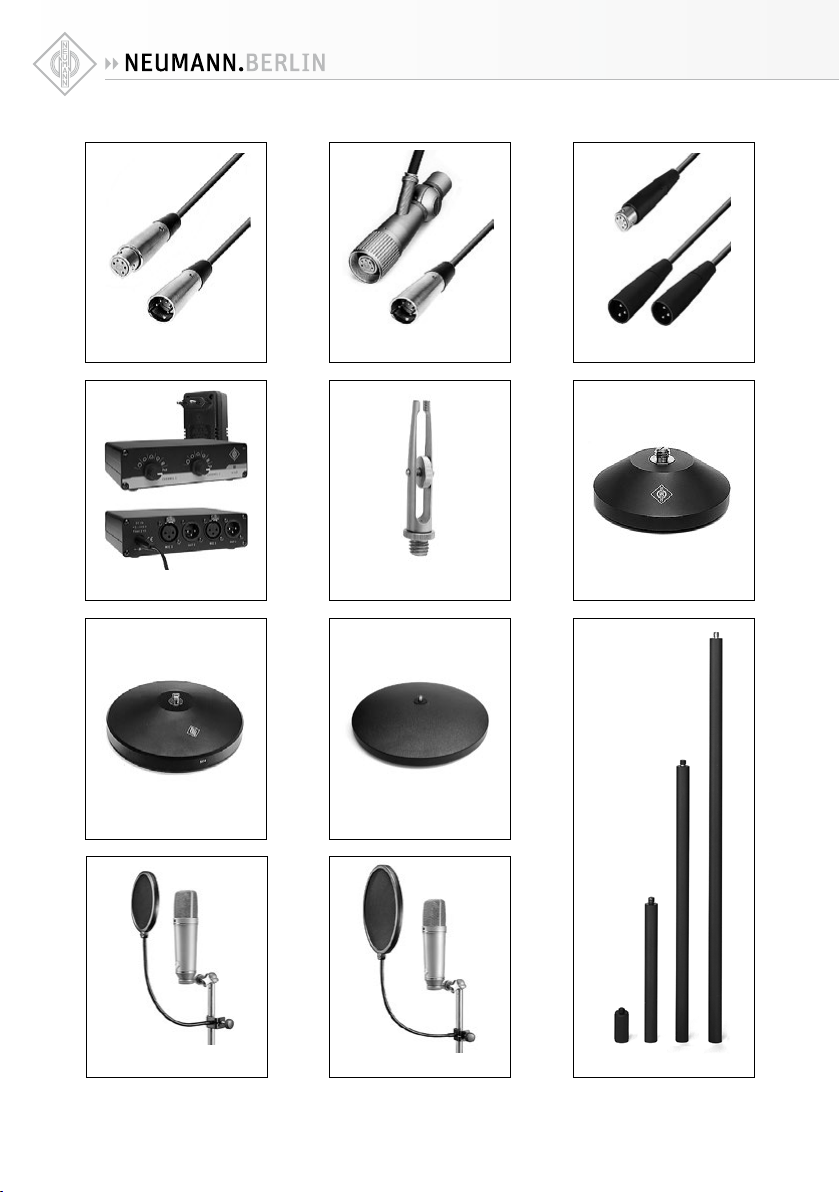
IC 5 (mt) IC 6 (mt)
AC 20
N 248
MF 4
PS 15 PS 20 a
MNV 87 (mt) MF 3
MF 5
STV...
14
Page 15

WS 69
USM 69 i
15
Page 16
Herstellererklärungen
Haungsausschluss
Die Georg Neumann GmbH übernimmt keinerlei Haung für einen
Gebrauch des Produkts, der von den in der Bedienungsanleitung
genannten technischen Voraussetzungen abweicht (z.B. Bedienungsfehler, falsche Spannung, Abweichung von empfohlenen
Korrespondenzgeräten). Dies gilt auch dann, wenn auf mögliche Schäden bei abweichendem Gebrauch hingewiesen wurde.
Jegliche Geltendmachung von Schäden und Folgeschäden, die
dem Benutzer aufgrund eines solchen abweichenden Gebrauchs
entstehen sollten, wird ausgeschlossen. Ausgenommen von
diesem Haungsausschluss sind Ansprüche aufgrund des Produkthaungsgesetzes.
Manufacturer declarations
Disclaimer
The product is sold “as-is” and the customer is assuming the entire
risk as to the product’s suitability for his needs, its quality and
its performance. In no event will Neumann be liable for direct,
indirect, special, incidental or consequential damages resulting
from any defect in the product or from its use in conjunction
with any microphones/products from other manufacturers, even
if advised of the possibility of such damages.
In Übereinstimmung mit den folgenden
Anforderungen:
WEEE-Richtlinie (2012/19/EU)
Hinweise zur Entsorgung
Das Symbol der durchgestrichenen Mülltonne auf Rädern auf
Produkt, Batterie/Akku (wenn vorhanden) und/oder Verpackung
weist Sie darauf hin, dass diese Produkte am Ende ihrer Lebensdauer nicht über den normalen Hausmüll entsorgt werden
dürfen, sondern einer separaten Entsorgung zuzuführen sind. Für
Verpackungen beachten Sie bitte die gesetzlichen Vorschrien
zur Abfalltrennung in Ihrem Land.
Weitere Informationen zum Recycling dieser Produkte erhalten
Sie bei Ihrer Gemeindeverwaltung, den kommunalen Sammeloder Rücknahmestellen oder bei Ihrem Sennheiser-Partner.
Das separate Sammeln von Elektro- und Elektronik-Altgeräten,
Batterien/Akkus (wenn vorhanden) und Verpackungen dient
dazu, die Wiederverwendung und/oder Verwertung zu fördern
und negative Eekte, beispielsweise durch potenziell enthaltene
Schadstoe, zu vermeiden. Hiermit leisten Sie einen wichtigen
Beitrag zum Umwelt- und Gesundheitsschutz.
Konformitätserklärung
Die Georg Neumann GmbH erklärt, dass dieses Gerät die anwendbaren CE-Normen und -Vorschrien erfüllt.
Neumann ist in zahlreichen Ländern eine eingetragene Marke
®
der Georg Neumann GmbH.
In compliance with the following
requirements:
WEEE-Directive (2012/19/EU)
Notes on disposal
The symbol of the crossed-out wheeled bin on the product, the
battery/rechargeable battery (if applicable) and/or the packaging
indicates that these products must not be disposed of with normal
household waste, but must be disposed of separately at the end
of their operational lifetime. For packaging disposal, please
observe the legal regulations on waste segregation applicable
in your country.
Further information on the recycling of theses products can be
obtained from your municipal administration, from the municipal
collection points, or from your Sennheiser partner.
The separate collection of waste electrical and electronic equipment, batteries/rechargeable batteries (if applicable) and packagings is used to promote the reuse and recycling and to
prevent negative eects caused by e.g. potentially hazardous
substances contained in these products. Herewith you make
an important contribution to the protection of the environment
and public health.
Declaration of Conformity
Georg Neumann GmbH hereby declares that this device conforms
to the applicable CE standards and regulations.
Neumann is a registered trademark of the Georg -Neumann
®
GmbH in certain countries.
Irrtümer und technische Änderungen vorbehalten • Errors excepted, subject to changes
Printed in Germany • Publ. 03/19 070301/A05
 Loading...