

Page 1
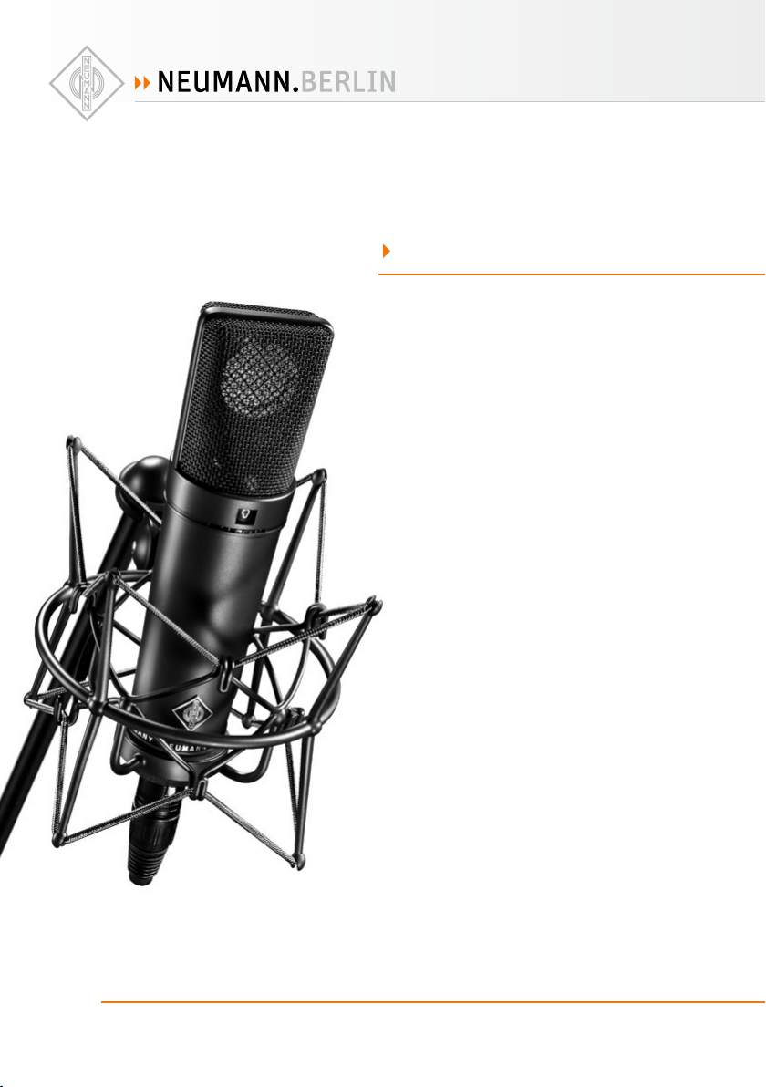
U 89
B
O M
· . · ·
() / - · - · @. · ..
Page 2

1. Einleitung
In dieser Anleitung nden Sie alle wichtigen Informationen für den Betrieb und die Pege des
von Ihnen erworbenen Produktes. Lesen Sie diese
Anleitung sorgfältig und vollständig, bevor Sie
das Gerät benutzen. Bewahren Sie sie so auf, dass
sie für alle momentanen und späteren Nutzer jederzeit zugänglich ist.
Weitergehende Informationen, insbesondere
auch zu den verfügbaren Zubehörteilen und den
Neumann-Servicepartnern, nden Sie jederzeit
auf unserer Website www.neumann.com. Die
Servicepartner können Sie auch telefonisch unter
+49 (0) 30 / 41 77 24 - 0 er fragen.
Auf unserer Website www.neumann.com nden
Sie in der Rubrik Downloads ergänzend folgende
PDF-Dateien:
• Betrieb an unsymmetrischen oder mittengeerdeten Eingängen
• Hinweise zur Pege des Mikrofons
Zum weltweiten Erfahrungsaustausch unter Neumann-Anwendern bieten wir auf unserer Website
das Neumann Online -Forum an, das sich durch die
integrierte Archivfunktion zu einem umfangreichen Know-How-Pool entwickelt hat.
2. Sicherheitshinweise
Der bestimmungsgemäße Gebrauch dieses Mikrofons ist die Wandlung akustischer in elektrische
Signale.
Schließen Sie das Mikrofon nur an Mikrofoneingänge und Speisegeräte an, die eine 48 V-Phantomspeisung nach IEC 61938 liefern.
Reparatur- und Ser vicearbeiten dürfen nur von erfahrenem und autorisiertem Fachpersonal durchgeführt werden. Wenn Sie das Gerät eigenmächtig
önen oder umbauen, erlischt die Gewährleistung.
Verwenden Sie das Gerät nur unter den in den
technischen Daten angegebenen Betriebsbedingungen. Lassen Sie das Gerät auf Raumtemperatur akklimatisieren, bevor Sie es einschalten.
Nehmen Sie das Gerät nicht in Betrieb, wenn es
beim Transport beschädig t wurde.
Verlegen Sie Kabel stets so, dass niemand darüber
stolpern kann.
Halten Sie Flüssigkeiten und elektrisch leitfähige
Gegenstände, die nicht betriebsbedingt notwendig sind, vom Gerät und dessen Anschlüssen fern.
Verwenden Sie zum Reinigen keine Lösungsmittel
oder aggressiven Reinigungsmittel.
Entsorgen Sie das Gerät nach den Bestimmungen
Ihres Landes.
3. Kurzbeschreibung
Das U 89 i ist ein Kondensator-Studiomikrofon
mit den Richtcharakteristiken Kugel, breite Niere,
Niere, Hyperniere und Acht.
Es zeichnet sich durch besonders saubere und
verfärbungsfreie Klangübertragung aus.
Prägende Besonderheit dieses Großmembransystems ist sein über 200° des Önungswinkels
bis 10 kHz nahezu linearer Frequenzgang. Damit
werden auch seitlich einfallende Signale neutral
verarbeitet.
Hilfreich ist diese Eigenscha z.B. dann, wenn
die Charakteristik des Aufnahmeraumes als gestalterischer Teil des gesamten Klangereignisses
behandelt werden soll.
Ein schaltbares Hochpasslter hebt die untere
Grenzfrequenz an und reduziert so den Einuss
von Nahbesprechungseekt und Körperschall.
Die zuschaltbare Dämpfung senkt das Übertragungsmaß um 10 dB und ermöglicht so die Verarbeitung sehr hoher Schalldrücke.
Typische Anwendungen dieses universellen Mikrofons nden sich z.B. als Stützmikrofon und bei
der Aufnahme von Bläsern, Streichern und Klavier.
Hervorzuheben ist seine Eignung für die Live
-Konzertaufnahme, wenn es um die originalgetreue Abbildung der Raumcharakteristik geht.
4. Lieferumfang
U 89 i (mt):
• Mikrofon U 89 i (mt)
• Bedienungsanleitung
• Holz-Etui
2
D
Page 3
5. Inbetriebnahme
Mikrofon einrichten
Befestigen Sie das Mikrofon auf einem ausreichend stabilen und standfesten Stativ. Verwenden Sie ggf. eine elastische Auängung, um die
Übertragung von Körperschallgeräuschen mechanisch zu unterdrücken. Setzen Sie dafür das Mikrofon von oben in den Innenkorb ein und schrauben Sie es mit der Rändelmutter am Innenkorb
fest. Zur Dämpfung von Wind- oder Popgeräuschen verwenden Sie bei Bedarf einen Wind- oder
Popschutz aus unserem Zubehörprogramm.
Mikrofon anschließen
Vorsicht: Eine falsche Versorgungsspannung
kann das Mikrofon beschädigen!
Schließen Sie das Mikrofon ausschließlich an ein
Netzgerät, einen Mikrofon-Vorverstärker, ein
Mischpult o.Ä. mit 48 V-Phantomspeisung nach
IEC 61938 an. Sie können alle P48-Speisegeräte
verwenden, die mindestens 0,8 mA je Kanal abgeben.
Vorsicht: Sehr laute Geräusche können Ihr
Gehör oder Ihre Lautsprecher schädigen!
Minimieren Sie an den angeschlossenen Wiedergabe- und Aufnahmegeräten die Lautstärke, bevor Sie das Mikrofon anschließen.
Verbinden Sie das Mikrofon über ein geeignetes
Kabel mit dem Mikrofoneingang Ihres weiterverarbeitenden Audiogerätes bzw. mit dem vorgesehenen P48-Speisegerät. Hinweise zur Anschlussbelegung nden Sie im Kapitel Technische Daten.
Kabellängen bis ca. 300 m zwischen Mikrofon und
nachfolgendem Verstärkereingang haben keinen
Einuss auf den Frequenzgang des Mikrofons.
Achten Sie beim Anschließen von Kabeln auf die
korrekte Verriegelung der Steckverbinder. Verlegen Sie die Kabel so, dass sie keine Stolpergefahr
darstellen.
Besprechen Sie das Mikrofon primär von der Seite
aus, auf der sich das Neumann-Logo bendet.
Erhöhen Sie an den weiterverarbeitenden Geräten
schrittweise den Lautstärkepegel.
Stellen Sie die Vorverstärkung (Gain) Ihres weiterverarbeitenden Gerätes so ein, dass bei höchstem Pegel keine Verzerrungen aureten.
Richtcharakteristik wählen
Es stehen fünf Charakteristiken zur Auswahl, die
eine individuelle Anpassung an die Aufnahmesituation ermöglichen: Kugel, Breite Niere, Niere,
Hyperniere und Acht. Den Drehschalter für die
Richtcharakteristik nden Sie auf der Vorderseite
unterhalb des Korbes.
Beim Umschalten der Richtcharakteristik kann
für einige Sekunden ein erhöhter Rauschpegel
aureten. Dieser entsteht durch die elektrische
Umladung der Mikrofonkapsel auf die jeweils notwendige Vorspannung und ist kein Zeichen für ein
Fehlverhalten. Reduzieren Sie sicherheitshalber
während des Umschaltens den Signalpegel der
nachfolgenden Geräte.
Vordämpfung einstellen
Die zuschaltbare Vordämpfung erhöht die Aussteuerungsgrenze, um extrem laute Schallereignisse ohne Übersteuerung weiterzuleiten.
Mit einem Schalter auf der Rückseite des Mikrofons wählen Sie zwischen „LIN“ und „–6 dB“.
Hochpass einstellen
Der Drehschalter auf der Rückseite des Mikrofons
bedient ein Hochpasslter, dessen Grenzfrequenz
zwischen 80 Hz und 160 Hz gew ählt werden kann.
Das Filter dämp tierequente Störsignale oder
dient der Kompensation des Nahbesprechungseektes.
In Stellung „LIN“ verhindert ein steiler Hochpass
die Übersteuerung des Ausgangsübertragers
durch Störeinüsse unterhalb des Hörbereichs.
Störschallunterdrückung
Der Übertragungsbereich des U 89 i reicht bis unter 20 Hz. Entsprechend empndlicher ist das Mikrofon natürlich auch für tierequente Störungen
wie Körperschall oder Wind- und Popgeräusche.
Daher empehlt sich ggf. die Verwendung einer
elastischen Auängung, eines Windschutzes
und/oder eines Popschirmes.
Tonte st
Sprechen Sie das Mikrofon einfach nur an. Anpusten oder „Anploppen“ führt zu gefährlichen
Schalldruckpegeln.
3
D
Page 4

6. Außerbetriebnahme und Auewahrung
Verringern Sie vor der Außerbetriebnahme und
dem Abziehen von Kabeln den Lautstärkepegel
Ihres weiterverarbeitenden Gerätes.
Schalten Sie erst dann die Phantomspeisung aus.
Trennen die Kabelverbindungen.
Ziehen Sie beim Lösen von Kabeln stets nur an
den Steckverbindern und nicht am Kabel.
7. Fehlercheckliste
Mikrofone, die nicht im Einsatz sind, sollte man
nicht auf dem Stativ einstauben lassen. Wird ein
Mikrofon längere Zeit nicht verwendet, sollte es
bei normalem Umgebungsklima staubgeschützt
auewahrt werden. Verwenden Sie hierfür einen
nicht fusselnden, ludurchlässigen Staubschutzbeutel oder die Originalverpackung des Mikrofons.
Fehler
Keine
Funktion
Keine Signalübertragung
Mögliche Ursachen
▶
Phantom-Speisespannung am
Mischpult oder am Speisegerät nicht
eingeschaltet.
Das Speisegerät ist nicht mit dem
Netzanschluss verbunden oder
Batterie fehlt.
Das Mikrofon ist nicht mit dem r ichtigen Mikrofonverstärker-Eingang des
nachfolgenden Gerätes verbunden.
Abhilfe
▶
Überprüfen Sie die entsprechenden Einstellungen auf dem Kanalzug.
Überprüfen Sie Netzanschluss oder Batterie des
Speisegeräts.
Überprüfen Sie den Signalweg
Aktivieren Sie ggf. den entsprechenden Eingang
auf dem zugeordneten Kanalzug des Mischpults.
4
D
Page 5

8. Technische Daten und
Anschlussbelegungen
Zulässige klimatische Verhältnisse:
Betriebstemperaturbereich .............. 0 ° C .. . +70 °C
Lagerungstemperaturbereich.......−20 °C ... +70 °C
Feuchtebereich ..... 0 %…90 % rel. hum. bei +20 °C
0 %…85 % rel. hum. bei +60 °C
Akustische Arbeitsweise ...........Druckgradienten-
Richtcharakteristik ................. Kugel, breite Niere,
Übertragungsbereich ......................20 Hz ...2 0 kHz
Feldübertragungs-
2)
faktor
............................. 8 mV/Pa = −42 dBV ± 1 dB
Nennimpedanz ...........................................1 50 Ohm
Nennlastimpedanz ................................. 1000 Ohm
Geräuschpegelabstand3), CCIR4) .................... 66 d B
Geräuschpegelabstand3), A-bewertet4) ..........77 dB
Ersatzgeräuschpegel, CCIR4) ..........................28 dB
Ersatzgeräuschpegel, A-bewertet4) ............ 17 d B-A
Grenzschalldruckpegel für
k < 0,5 % Klirrfak tor ...................................... 1 34 dB
mit Vordämpfung .......................................... 140 d B
Max. Ausgangsspannung ...........800 mV (0,3 dBu)
Speisespannung6) ..................................... 48 V ± 4 V
Stromaufnahme6) .......................................... 0,8 mA
Erforderlicher Steckverbinder......................XLR3F
Gewicht ........................................................... 400 g
Abmessungen ........................... Ø 46 mm x 185 mm
94 dB SPL ents pr. 1 Pa = 10 µbar
0 dB entspr. 20 µPa
1)
Niere, Hyperniere,
5)
empfänger
Acht
Das Mikrofon besitzt einen symmetrischen Übertrager-Ausgang. Der 3-polige XLR-Steckverbinder
weist folgende normgerechte Belegung auf:
Pin 1: 0 V/Masse
Pin 2: Modulati on (+Phas e)
Pin 3: Modulation (–Pha se)
9. Ausgewähltes Zubehör*
(Fotos im Anhang)
Elastische Auängung
EA 89 A .................... ni ................ Best .-Nr. 00 7 1 9 5
Neigevorrichtung
MNV 87 .................... ni ................ Best.-Nr. 006804
Halterung
DS 120 .....................sw ............... Best.-Nr. 0 07 3 4 3
SG 289 ....................ni ................ Best.-Nr. 006619
Popschutz
PS 15 ........................ sw ............... Bes t.-Nr. 0 0 8 4 7 2
PS 20 a ....................sw ............... B est.-Nr. 0 084 8 8
Windschutz
WS 89 ......................sw ............... B est.-Nr. 0 07 1 9 7
Netzgerät
N 248 ....................... sw ............... Be st.-Nr. 00 8 5 3 7
Verbindungskabel
IC 3 mt (10 m) ..........sw ............... Best.-Nr. 006543
IC 4 (10 m) ...............ni ................ Best.-Nr. 0 0 6 5 4 7
Bedeutung der Farbcodierungen:
ni = nickel, sw = schwarz
1)
Alle Werte für nicht-kondensierende Feuchtigkeit.
Die Wer te gelten für sa ubere, gep egte Mikro fone bzw.
Mikrofonkapseln. Schmutzablagerungen jeglicher Art auf
Kapse ln oder Membr anen können d ie genannten We rte
einschränken.
2)
bei 1 kHz an 1 kOhm Nennlastimpedanz.
3)
bez ogen auf 94 dB SPL
4)
nach IEC 6026 8-1; CCIR- Bewertun g nach CCIR 468-3 ,
Quasi -Spitzenwe rt; A-Be wertung nac h IEC 61672 -1,
Eektivwert
5)
Klirrfaktor des Mikrofonverstärkers bei einer Eingangs-
spannu ng, die der von d er Kapsel bei m entsprec henden
Schalldruck abgegebenen Spannung entspricht.
6)
Phanto mspeisung (P4 8, IEC 61938).
* Ausführli che Besch reibungen un d weitere Ar tikel nden Si e
in unserem Zubehörkatalog oder unter www.neumann.com
5
D
Page 6

1. Introduction
This manual contains essential information for
the operation and care of the product you have
purchased. Please read the instructions carefully and completely before using the equipment.
Please keep this manual where it will be accessible at all times to all current and future users.
Additional information, in particular concerning available accessories and Neumann service
partners, can always be found on our website:
www.neumann.com. Information about service
partners can also be obtained by telephone:
+49 (0) 30 / 41 77 24 - 0.
The following related les are available in PDF
format in the Downloads section of our website
www.neumann.com:
• Operation with Unbalanced or Center Tap
Grounded Inputs
• Some Remarks on Microphone Maintenance
The Neumann online forum on our website enables Neumann users worldwide to share their
experiences. Through its integrated archive function, the forum has developed into an extensive
knowledge pool.
2. Safety instructions
The microphone has the intended purpose of converting acoustic signals into electrical signals.
Connect the microphone only to microphone inputs and devices which supply 48 V of phantom
power in accordance with IEC 61938.
Repairs and servicing are to be carried out only by
experienced, authorized service personnel. Unauthorized opening or modication of the equipment shall void the warranty.
Use the equipment only under the conditions
specied in the “Technical data” section. Allow
the equipment to adjust to the ambient temperature before switching it on. Do not operate the
equipment if it has been damaged during transport.
Always run cables in such a way that there is no
risk of tripping over them.
Unless required for operation, ensure that liquids
and electrically conductive objects are kept at a
safe distance from the equipment and its connections.
Do not use solvents or aggressive cleansers for
cleaning purposes.
Dispose of the equipment in accordance with the
regulations applicable to the respective country.
3. Brief description
The U 89 i is a condenser studio microphone with
a transformer output and the directional characteristics omnidirectional, wide angle cardioid,
cardioid, hypercardioid and gure-8.
The microphone features exceptionally clean
sound transmission which is free of coloration.
A special feature of this large-diaphragm system
is its almost linear frequency response up to
10 kHz, throughout an incidence angle of 200°.
This permits neutral processing even of signals
originating from the side.
This feature is particularly important, for instance, when the characteristics of the room are
to be treated as an integral aspect of the overall
sound.
A switchable high-pass lter increases the lower
cuto frequency, thus reducing the inuence of
the proximity eect and structure-borne sound.
The pre-attenuation switch reduces the microphone sensitivity by 10 dB, thus allowing the processing of very high sound pressure levels.
Typical applications of this versatile microphone
include use as a spot microphone, as well as the
recording of winds, strings and piano.
Special mention should be made of the suitability
for recording live concerts, when it is important
to obtain an accurate representation of the spatial
characteristics.
4. Scope of delivery
U 89 i (mt):
• U 89 i (mt) microphone
• Operating manual
• Wooden box
EN
66
Page 7

5. Setup
Mounting the microphone
Attach the microphone to a stable, sturdy stand.
Use an elastic suspension, if necessar y, for the
mechanical suppression of structure-borne noise.
For this purpose set the microphone into the inner
cage from above, and secure it to the inner cage
with the threaded nut. If required, use a windscreen or popscreen from our range of accessories in order to suppress w ind or pop noise.
Connecting the microphone
Caution: An incorrect supply voltage can dam-
age the microphone!
Attach the microphone only to a power supply
unit, a microphone preamplier, a mixing console
or other equipment which has phantom power
with 48 V (P48), in accordance with IEC 61938.
Any P48 power supply equipment can be used
which supplies at least 0.8 mA per channel.
Caution: Very loud noise can damage loud-
speakers or your hearing!
Minimize the volume of connected playback and
recording equipment before connecting the microphone.
Using a suitable cable, connect the microphone
to the microphone input of the audio equipment
to be used for subsequent processing, or to the
designated P48 power supply equipment. Information concerning connector assignment can be
found in the “Technical data” section.
Cable lengths of up to approximately 300 m between the microphone and the subsequent amplier input have no eect on the frequency response of the microphone.
When connecting the cables, ensure that the connectors are locked correctly. Run the cables in
such a way that there is no risk of tripping over
them.
The microphone is to be addressed primar ily from
the side on which the Neumann logo is located.
Gradually increase the volume of the connected
equipment.
Set the gain of the connected equipment so that
no distortion occurs at the highest sound pressure level.
Selecting the directional characteristic
There are ve selectable directional characteristics, which allow the microphone to be adapted to
individual recording situations: omnidirectional,
wide-angle cardioid, cardioid, hypercardioid and
gure-8. The rotary switch for the directional
characteristics is located on the front of the microphone, below the headgrille.
When the directional characteristic is changed,
an increased noise level may occur for some
seconds. This does not indicate a malfunction,
but arises due to the electrical recharging of the
microphone capsule to the appropriate bias. A s a
precaution, reduce the signal level of connected
equipment when changing the directional characteristic.
Setting the pre-attenuation
The switchable pre-attenuation increases the
maximum signal level in order to avoid overloading when transmitting signals at extremely high
sound pressure levels.
“LIN” or “–6 dB” can be selected by means of a
switch on the back of the microphone.
Setting the high-pass lter
The high-pass lter can be set via a rotary switch
on the back of the microphone. A cuto frequency
of 80 Hz or 160 Hz can be selected. The lter can
be used to suppress low-frequency interference
or to compensate for the proximity eect.
When the “LIN” setting is used, a steep low-cut
prevents the output transformer from being overloaded by interference below the audio range.
Suppressing noise interference
The frequency response of the U 89 i extends
below 20 Hz. The microphone is of course correspondingly sensitive to low-frequency interference such as structure-borne noise and wind or
pop noise. Depending upon the situation, the use
of an elastic suspension, a windscreen and/or a
popscreen is therefore recommended.
Sound test
Simply speak into the microphone. Do not blow
into the microphone or subject it to pop noise,
since this can easily result in hazardous sound
pressure levels.
77
EN
Page 8

6. Shutdown and storage
Before switching o the microphone or disconnecting the cables, reduce the volume of connected equipment.
Only then should the phantom power be switched
o.
Disconnect the cables.
When disconnecting a cable, always pull only on
the connector and not on the cable itself.
7. Troubleshooting
Microphones which are not in use should not be
allowed to remain on the stand gathering dust. A
microphone which is unused for a prolonged period should be stored under normal atmospheric
conditions, and should be protected from dust.
For this purpose, use a lint-free, air-permeable
dust cover or the original packaging of the microphone.
Problem
Microphone not
operating
No signal
transmission
Possible causes
▶
The phantom power supply voltage is
not switched on at the mixing console
or at the power supply equipment
The power supply equipment is not
connected to the power supply line or
there is no battery
The microphone is not connected
to the correct microphone amplier
input of the subsequent equipment
Solution
▶
Check the corresponding channel settings
Check the connection to the power supply
line or check the bat tery of the power supply
equipment
Check the signal path
If necessary, activate the appropriate input on
the corresponding channel of the mixing console
EN
88
Page 9

8. Technical data and
connector assignments
Permissible atmospheric conditions:
Operating temperature range ........... 0 ° C .. . +70° C
Storage temperature range ...........−20 °C ... +70 °C
Humidity range ..................... 0 % … 90 % at +20 °C
Acoustical operating
principle ...................................... Pressure gradient
Directional pattern ......................................... Omni,
Frequency range ...............................20 Hz ...2 0 kHz
Sensitivity
2)
.....................8 mV/Pa = −42 dBV ± 1 dB
Rated impedance ......................................15 0 ohms
Rated load impedance ..........................1000 ohms
Signal-to-noise ratio3), CCIR4) ........................ 6 6 dB
Signal-to-noise ratio3), A-weighted4) ..............77 dB
Equivalent noise level, CCIR4).........................28 dB
Equivalent noise level, A-weighted4) .......... 17 d B-A
Max. SPL for
5)
less than 0.5 % THD ...................................... 13 4 dB
with preattenuation ..................................... 140 dB
Max. output voltage ....................800 mV (0.3 dBu)
Supply voltage6) ....................................... 48 V ± 4 V
Current consumption
Matching connector .......................................XLR3F
Weight ............................................................. 400 g
Dimensions ............................... Ø 46 mm x 185 mm
94 dB SPL equiv. to 1 Pa = 10 µbar
0 dB equiv. to 20 µPa
0 % … 85 % at +60 °C
wide angle cardioid,
cardioid, hypercardioid,
6)
................................ 0. 8 mA
1)
transducer
gure 8
The microphone has a balanced transformer output. The 3-pin XLR connector has the following
standard pin assignments:
Pin 1: 0 V/Ground
Pin 2: M odulatio n (+phase)
Pin 3: Mo dulation (–phas e)
9. Selected Accessories*
(see photos in appendix)
Elastic Suspension
EA 89 A .................... ni ................ Cat. No. 007195
Auditorium Hanger
MNV 87 .................... ni ................ Cat . No. 006804
Mount
DS 120 ..................... blk .............. Cat. No. 007343
SG 289 ....................ni ................ Cat. No. 006619
Popscreen
PS 15 ........................ blk .............. Cat. No. 008472
PS 20 a ....................blk .............. Cat. No. 0 8 4 8 8
Windscreen
WS 89 ......................blk .............. Cat. No. 007 197
Power Supply
N 248 ....................... blk .............. Cat. No. 008537
Connecting Cable
IC 3 mt (10 m) ..........blk .............. Cat. No. 006543
IC 4 (10 m) ...............ni ................ Cat. No. 006547
Meaning of color codes:
ni = nickel, blk = black
1)
All valu es for non- condensin g humidity. Th e values are
valid fo r clean and well -looked- aer microp hones or
microp hone capsul es, respe ctively. An y kind of pollu tion
of caps ules and memb ranes may res trict the s aid values .
2)
at 1 kHz into 1 kohms r ated load imp edance.
3)
re 9 4 dB SPL
4)
accord ing to IEC 60268-1; CC IR-weigh ting acccor ding
to CCIR 468 -3, quasi peak ; A-weight ing accordi ng to
IEC 6167 2-1 , R MS
5)
THD of m icrophone a mplier at an in put voltage e quivalent
to the ca psule output a t the speci ed SPL.
6)
Phantom p owering (P4 8, IEC 61938).
* Det ailed descr iptions an d additiona l article s can be found
in our acc essorie s catalog or a t: www.neu mann.com
99
EN
Page 10

10. Frequenz- und Polardiagramme
10. Frequency responses and polar patterns
1010
Page 11

gemes sen im freien S challfeld na ch IEC 60268- 4, Toleranz ± 2 dB
measur ed in free- eld condit ions (IEC 6026 8-4), toler ance ±2 dB
1111
Page 12

EA 89 A
MNV 87
SG 289
PS 15
Haungsausschluss
Die Geo rg Neumann GmbH übernimmt keiner lei Hau ng für Fol gen
eines un sachgemäßen G ebrau chs des P roduk ts, d.h. die Folgen ein es
Gebrauchs, der von den in der Bedienungsanleitung genannten technischen Voraussetzungen abweicht (z.B. Bedienungsfehler, mechanische
Beschädigungen, falsche Spannung, Abweichung von empfohlenen
Korre spondenzge räten). Jeglic he Haung der G eorg Neumann G mbH für
Schäden und Folgeschäden, di e dem Ben utzer aufgrun d eines solchen
abweichenden Gebrauchs entstehen sollten, wird ausgeschlossen. Ausgenomm en von die sem Ha ungsa ussch luss sin d Anspr üche au fgrund
zwingender gesetzlicher Haung, wie z.B. nach Produkthaungsgesetz.
Limitation of Liability
Georg N eumann G mbH shal l not be liable for consequences of a n inappropr iate use of the prod uct not b eing in complianc e with th e techni cal allowance in th e user manual such a s handlin g error s, mechanical
spoiling , fals e voltag e and usin g other th an the recommen ded correspond ence devices . Any liability o f Georg Neuman n GmbH for any damages inc luding indirect, con sequential , special, in cidental and pu nitive
damage s based o n the use r’s non-comp liance w ith the u ser manu al or
unreas onable u tilization of the produ ct is her eby excl uded as to t he
extent p ermit ted by law. T his limit ation o f liabilit y on damag es is not
applic able for the liabi lity under Eur opean produc t liability co des or for
users i n a state or count ry where suc h damages can not be limited .
Irrtümer und technische Änderungen vorbehalten • Errors excepted, subject to changes
Printed in Germany • Publ. 08/15 069422/A03
N 248WS 89
Konformitätserklärung
Die Geo rg Neumann GmbH e rklär t, dass dieses Gerät die anwend baren
CE-Normen und -Vorschrien erfüllt.
Neumann ist in zahlreichen Ländern eine eingetragene Marke der Ge-
®
org Neum ann GmbH.
Declaration of Conformity
Georg N eumann GmbH he reby declare s that this devi ce confor ms to the
applicable CE standards and regulations.
Neumann is a regi stered tradem ark of the Georg Neumann GmbH in
®
certain countries.
 Loading...