

Page 1
TLM
B
O M
· . · ·
() / - · - · @. · ..
Page 2

1. Einleitung
In dieser Anleitung nden Sie alle wichtigen Informationen für den B etrieb und die P ege des
von Ihnen er worbenen Pro duktes. Lese n Sie diese
Anleitung sorgfältig und vollständig, bevor Sie
das Gerät b enutzen. Bew ahren Sie sie so auf, das s
sie für alle momentanen und späteren Nutzer jederzeit zugänglich ist.
Weitergehende Informationen, insbesondere
auch zu den verfügbaren Zubehörteilen und den
Neumann-Servicepartnern, nden Sie jederzeit
auf unserer Website ww w.neumann.com. Die
Servicepartner können Sie auch telefonisch unter
+49 (0) 30 / 41 77 24 - 0 er fragen.
Auf unserer Website ww w.neumann.com nden
Sie in der Rubr ik Downloads ergänzend folgende
PDF-Dateien:
• Betrieb an unsymmetrischen oder mittengeerdeten Eingä ngen
• Hin weise zur P e ge des Mikrofons
Zum weltweiten Erfahrungsaustausch unter Neumann-Anwendern bieten wir auf unserer Website
das Neumann Online-Forum an, das sich durch
die integrierte Archivfunktion zu einem umfangreichen Know-How-Pool ent wickelt hat.
2. Sicherheitshinweise
Der bes timmungsgemäß e Gebrauch dies es Mikrofons ist die Wandlung akustischer in elektr ische
Signale.
Schließen Sie das Mikro fon nur an Mikrofon-
eingänge und Speisegeräte an, die eine 48VPhantomsp eisung nach IEC 61938 liefern .
Reparatur- und Serv icearbeiten dürfen nur von
erfahrenem und autorisiertem Fachpersonal
durchgeführt werden. Wenn Sie das Gerät eigenmächtig ö nen oder umbauen, erlischt die Gewährleistung.
Verwenden Sie das Gerät nur unter den in den
technischen Daten angegebenen Betriebsbedingungen.
Lassen Sie das Gerät auf Raumtemperatur akklimatisie ren, bevor Sie es ein schalten.
Nehmen Sie das Gerät nicht in Betr ieb, wenn es
beim Transport beschädigt wurde.
Verlegen Sie K abel stets so, da ss niemand darübe r
stolpern kann.
Halten Sie Flüssigkeiten und elektrisch leitfähige
Gegenstände, die nicht betriebsbedingt notwendig sind, vom G erät und dessen A nschlüssen fer n.
Verwend en Sie zum Reinigen keine Lösu ngsmittel
oder aggres siven Reinigungsmittel.
Entsorgen Sie das Gerät nach den Bestimmungen
Ihres Lan des.
3. Kurzbeschreibung
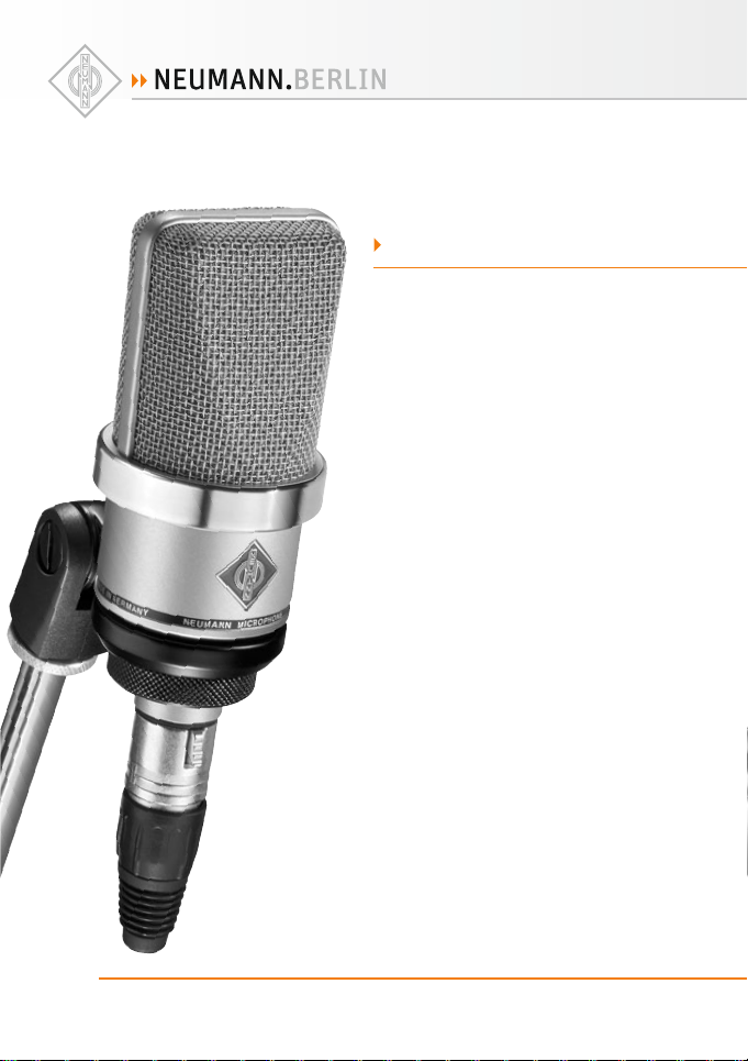
Das TLM102 ist ein Kondens ator-Studiomikrofon
in transformatorloser Schaltungstechnik (TLM)
mit der Rich tcharakterist ik Niere.
Mit seinem transformatorlosen Konzept ermöglicht das TLM 102 eine besonders saubere, verfärbungsfreie Klangübertragung und höchste Aussteuerb arkeit bei geringem E igenrauschen.
Das TLM 102 ist mit einer Großmembrankapsel
ausgerüs tet. Diese hat einen bis ca. 6 kHz eb enen
Frequenzg ang, darüber eine br eite, ache P räsenzanhebung.
4. Lieferumfang
TLM 102 (bk):
• Mik rofon TLM 102 (bk)
• Sta tivgelenk SG 2
• Bedienungsanleitung
TLM 102 (bk) Studi o-Set:
• Mik rofon TLM 102 (bk),
• Elastische Au ängung EA 4,
• Bedienungsanleitung
bk = schwar z
5. Inbetriebnahme
Mikrofon einrichten
Befest igen Sie das Mikrofon auf einem ausreichend stabi len und standfesten St ativ. Verwenden
Sie ggf. eine elastische Au ängung , um die Übertragung von Körperschallgeräuschen mechanisch
zu unterdrücken. Setzen Sie dafür das Mikrofon
von oben in den Innenkorb ein und schrauben
Sie es mit der Rändelmut ter am Innenkorb fest.
Zur Dämpfung von Wind- oder Popgeräuschen
verwenden Sie bei Bedarf einen Wind- oder Popschutz aus unserem Zubehörprogramm.
2
D
Page 3

Mikrofon anschließen
Vorsicht: Ein e falsche Versorgungsspann ung
kann das Mikrofon beschädigen!
Schließen Sie das Mikrofon ausschließlich an
ein Netzgerät, einen Mikrofon-Vorverstärker, ein
Mischpult o.Ä. mit 4 8 V-Phantomspeisung nach
IEC 61938 an. Sie können alle P4 8-Speisegeräte
verwenden, die mindestens 3,5 mA je Kanal abgeben.
Vorsicht: Se hr laute Geräusche kön nen Ihr
Gehör oder Ihre Lautsprecher schädigen!
Minimieren Sie an den angeschlossenen Wiedergabe- und Aufnahmegeräten die Lautstärke, be vor Sie das Mik rofon anschließ en.
Verbinden Sie das Mikrofon über ein geeignetes
Kabel mit dem Mikrofoneingang Ihres weiter verarbeitenden Audiogerätes bzw. mit dem vorgesehenen P48-Speisegerät. Hinweise zur Anschlussbelegun g nden Sie im Kapitel Tech nische Daten.
Kabellängen bis ca. 30 0 m zwischen Mikrofon
und nachfo lgendem Verstär kereingang haben kei nen Ein uss auf den Frequ enzgang des Mikr ofons.
Achten Sie beim Anschließen von Kabeln auf die
korrekte Verriegelung der Steckverbinder. Verlegen Sie die Kabel so, dass sie keine Stolpergefahr
darstellen.
Besprechen Sie das Mikrofon von der Seite aus,
auf der sich d as Neumann-Logo b e ndet.
Erhöhen Si e an den weiterver arbeitenden Ger äten
schrittweise den Lautstärkepegel.
Stellen Sie die Vor verstärkung (Gain) Ihres weitervera rbeitenden Gerät es so ein, dass bei höc hstem Pegel kein e Verzerrungen au reten.
Störschallunterdrückung
Der Übertragungsbereich des TLM 102 reicht bis
unter 20 Hz. En tsprechend emp ndlich ist das M ikrofon natürlich auch für tie requente Störungen
wie Körperschall oder Wind- und Popgeräusche.
Daher emp ehlt sich ggf. die Verwendung einer
elastischen Au äng ung, eine s Windschutzes
und/oder eines Popschirmes.
Tont est
Sprechen Sie das Mikrofon einfach nur an. Anpusten oder „Anploppen“ führt zu gefährlichen
Schalldruckpegeln.
6. Außerbetriebnahme und Aufbewahrung
Verringern Sie vor der Außerbetriebnahme und
dem Abziehen von Kabeln den Lautstärkepegel
Ihres weiterverarbeitenden Gerätes.
Schalten Sie e rst dann die Phantomsp eisung aus.
Trennen Sie die Kab elverbindungen.
Ziehen Sie beim Lösen von Kabeln stet s nur an
den Steckv erbindern und nicht am Kab el.
Mikrofone, die nicht im Einsatz sind, sollte man
nicht auf dem Stativ einstauben lassen. Wird ein
Mikrofon längere Zeit nicht verwendet, sollte es
bei normalem Umgebungsklima staubgeschützt
au ewahrt werden. Verwenden Sie hierfür einen
nicht fusselnden, lu durchlässigen Staubschutzbeutel oder die Orig inalverpackung de s Mikrofons.
3
D
Page 4

7. Fehlercheckliste
Fehler
Keine
Funkti on
Keine Signa lübertragung
Ton verzerrt Falsch eingestellte Eingangsemp-
Ton klingt dump f,
räumlich
Mögliche Ursachen
▶
Phantom-Speisespannung am
Mischpult o der am Speisegerä t nicht
eingeschaltet.
Das Speise gerät ist nicht mit de m
Netzan schluss verbunde n oder
Batterie fehlt.
Das Mikrof on ist nicht mit dem ri chtigen Mikrofonverstärker-Eingang des
nachfol genden Gerätes ver bunden.
ndlichkeit oder Vorverstärkung des
nachfolgenden Verstärkers.
Windein uss Benutz en Sie einen geeignet en Windschutz
Explosivlaute Benutzen Sie einen geeigneten Popschutz
Körpers challübertra gung Benutze n Sie eine geeignete ela stische Au än-
Richtchar akteristik n icht beachtet Prüfen Sie , ob das Mikrofon von de r richtigen
8. Technische Daten und
Anschlussbelegungen
Zulässige klimatische Verhältnisse:1)
Betrie bstemperaturb ereich ...............0 °C … +70 °C
Lagerun gstemperaturb ereich........–20 °C … +70 °C
Feuchtebe reich ..... 0 %…90 % rel. hum. bei +20 °C
Akust. A rbeitsweise ................... Druckg radienten-
Richtchar akteristik .........................................Niere
Übertr agungsbereic h ...................... 20 Hz... 20 kHz
Feldübertragungs-
2)
faktor
Nennimpe da nz ............................................ 50 Ohm
Nennlas timpedanz .................................100 0 Ohm
Geräuschpegelabstand
CCIR4) ............................................................... 73 dB
Geräuschpegelabstand3),
A-bewertet4) ....................................................82 dB
0 %…85 % rel. hum. bei +60 °C
empfänger
...................................................... 11 mV/Pa
3)
,
Abhilfe
▶
Überprüfen Sie die entsprechenden Einstellungen auf dem Ka nalzug.
Überprüfen Sie Netzanschluss oder Batterie des
Speisegeräts.
Überpr üfen Sie den Signalwe g
Aktivieren Sie ggf. den entsprechenden Eingang
auf dem zuge ordneten Kanalzu g des Mischpults .
Verringe rn Sie die Eingangsemp nd lichkeit oder
Vorverstärkung de s nachfolgenden Gerätes so,
dass eine ausreichende Aussteuerungsreserve
bleibt.
(Zubehör).
(Zubehör).
gung (Zubehör).
Seite ange sprochen wird . Orientieren Si e sich
am Neumann-Logo.
Ersatzgeräuschpegel,
4)
............................................................... 21 dB
CCIR
Ersatzgeräuschpegel,
A-bewertet4) ................................................1 2 d B-A
Grenzschalldruckpegel5)
für k < 0,5 % ................................................. 144 dB
Max. Aus gangsspannung f ür k < 5 % ............ 1 3 dBu
Stromvers orgu ng ............................................. P48
Stromaufn ahme ............................................ 3,5 mA
Erford erliche Steckve rbinder ...................... XLR 3 F
Gewich t ............................................................210 g
Abmes sungen ...................................Ø 52 x 116 mm
94 dBSPL en tspr. 1 Pa = 10 μbar
0 dB entspr. 20 μ Pa
6)
4
D
Page 5

Das Mikrofon besit zt einen symmetrischen, übertragerlosen Ausgang. Der 3-polige XLR-Steckverbinder weist folgende normgerechte Belegung
auf:
Pin 1: 0 V/Masse
Pin 2: Modulation (+Phase)
Pin 3: Modulation (–Phase)
9. Ausgewähltes Zubehör*
(Fotos im Anhang)
Elastische Aufhängungen
EA 1 .......................... ni ................ Best .-Nr. 008449
EA 1 mt .....................sw ...............B est.- Nr. 008450
Mikrofonneigevorrichtung
MNV 87 ....................ni ................ Be st.-Nr. 006804
MNV 87 mt ...............sw ............... Best .-Nr. 006806
Stativgelenke, weitere mechanische Adapter
DS 120 .....................sw ............... Bes t.-Nr. 007343
SG 2 ..........................sw ............... Best.- Nr. 008636
Tisch- und Fußbodenständer
MF 4 .........................sw ...............Best.-Nr. 0073 37
Schaumstoff windschutz
WS 2 .........................sw ............... Best .-Nr. 008637
Popschutz
PS 15 .......................sw ...............Best.-Nr. 008472
PS 20 a ...................sw ...............Best .-Nr. 008488
Netzgerät
N 248 .......................sw ............... Best.-Nr. 0085 37
Anschlusskabel
IC 3 mt .....................sw ............... Best.-Nr. 006543
IC 4 ..........................ni ................ B est.- Nr. 006547
IC 4 m t .....................sw ...............Be st.-Nr. 006557
Verbin dung skab el
AC 25 .......................ni ................ Best.-Nr. 006600
Bedeutung der Farbcodierungen:
ni = nickel, s w = schwarz, gr = grau
1)
Alle Werte für nicht-kondensierende Feuchtigkeit.
Die Wert e gelten für sau bere, gep eg te Mikrofon e bzw.
Mikrofo nkapseln . Schmutzab lagerunge n jeglicher A rt auf
Kapsel n oder Membra nen können di e genannten Wer te
einschränken.
2)
bei 1 kHz an 1 kO hm Nennlas timpedanz
3)
bezo gen auf 94 dB SPL
4)
nach IEC 60 268-1;
CCIR-Bewer tung nach CCIR 468-3, Quasi -Spitzenwert;
A-Bew ertung nac h IEC 61672-1, E ektivwert
5)
Klirr faktor de s Mikrofonv erstärker s bei einer Eing angs-
spannun g, die der von de r Kapsel beim e ntsprech enden
Schalldruck abgegebenen Spannung entspricht.
6)
nach IEC 6193 8
* A usführli che Besc hreibunge n und weitere A rtikel n den Sie
in unserem Zubehörkatalog oder unter www.neumann.com
5
D
Page 6

1. Introduction
This manual co ntains essenti al information for t he
operation and care of the product you have purchased. Please read the instructions carefully and
completely before using the equipment. Please
keep this ma nual where it will be access ible at all
times to all c urrent and future use rs.
Additional information, in particular concerning available accessories and Neumann service
partners, can always be found on our website:
www.neumann.com. Information about service
partners can also be obtained by telephone:
+49 (0) 30 / 41 77 24 - 0.
The follow ing related les are available in PDF
format in the Downloads section of our website
www.neumann.com:
• Operation with Unbalanced or Center Tap
Grounded Inputs
• Some Remarks on Microphone Maintenance
The Neumann online forum on our website en ables Neumann users worldwide to share their
experiences. Through it s integrated archive function, the forum has developed into an extensive
knowled ge pool.
2. Safety instructions
The microp hone has the intende d purpose of converting acoustic signals into electr ical signals.
Connect the microphone only to microphone
inputs an d devices which suppl y 48 V of phantom power in acc ordance with IEC 61938.
Repairs and servicing are to be c arried out only
by experienced, authorized service personnel.
Unauthorized opening or modi cation of the
equipmen t shall void the warrant y.
Use the equipment only under the conditions
speci ed in th e “Technical data” sec tion.
Allow the equ ipment to adjust to the ambi ent temperature before switching it on.
Do not operate the equipment if it has been damaged during transport.
Always run cables in such a way that there is no
ris k of tri pping o ver the m.
Unless required for operation, ensure that liquids
and electrically conductive objects are kept at a
safe distance from the equipment and its connections.
Do not use solvents or aggressive cleansers for
cleaning purposes .
Dispose of the equipment in accordance with the
regulations applicable to the respective country.
3. Brief description
The TLM 102 is a condenser studio microphone
with transformerless (TLM) circuit technology
and a cardioi d directional cha racteristi c.
The transformerle ss design of the TLM 102 permits exce ptionally clean sou nd transmission w ith
no colorat ion, as well as a maximum dynamic
range wit h low self-noise.
The microphone houses a large diaphragm c apsule. It has a linear frequency response up to approximately 6 kHz, above which there is a broad,
a t p r e s e n c e b o o s t .
4. Scope of delivery
TLM 102 (bk):
• TL M 102 (bk) microphone
• SG 2 s tand mount
• Operating manual
• Wooden box
TLM 102 (bk) Studi o set:
• TL M 102 (bk), microphone
• E A 4 elastic suspe nsion
• Operating manual
bk = black
5. Setup
Mounting the microphone
Attach the microphone to a stable, sturdy stand.
Use an elastic suspension, if necessary, for the
mechanical suppression of structure-borne noise.
For this purp ose set the micropho ne into the inner
cage from above, and secure it to the inner cage
with the threaded nut. If required, use a windscreen or popscreen from our range of accessories in or der to suppress wind o r pop noise.
EN
66
Page 7

Connecting the microphone
Caution : An incorrect supply v oltage can dam-
age the micro phone!
Attach the microphone only to a power supply
unit, a micro phone preampli er, a mixing console
or other equipment which has phantom power
with 48 V (P48), in accordance with IEC 61938.
Any P48 power supply equipment can be used
which supplie s at least 3.5 mA pe r channel.
Caution : Very lou d noise can damage loud-
spe akers o r your he aring !
Minimize the volume of connected playback and
recording equipment before connecting the microphone.
Using a suitable cable, connect the microphone
to the microphone input of the audio equipment
to be used for subsequent processing, or to the
designated P48 power supply equipment. Information concerning connector assignment can be
found in the “ Technic al data” section .
Cable leng ths of up to approximately 300 m between the microphone and the subsequent am pli er input have no e ect on the frequency response of the microphone.
When connecting the cables, ensure that the connector s are locked corre ctly. Run the cable s in such
a way that there is no risk of tripping over them.
Address the microphone from the side on which
the Neumann logo is located.
Gradually increase the volume of the connected
equipment
Set the gain of the connected equipment so that
no distortion occurs at the highest sound pressure level.
Suppressing noise interference
The frequency response of the TLM 102 extends
below 20 Hz. The microphone is of course correspondingly sensitive to low-frequency interference such as structure-borne noise and wind or
pop noise. Depending upon the situation, the use
of an elastic suspension, a windscreen and/or a
popscreen is therefore recommended.
Sound test
Simply speak into the microphone. Do not blow
into the microphone or subject it to pop noise,
since this can easily result in hazardous sound
pressure levels.
6. Shutdown and storage
Before switching o the microphone or disconnecting the cable s, reduce the volume of connected equipment.
Only then sho uld the phantom power be sw itched
o .
Disconn ect the cables .
When disconnecting a cable, always pull only on
the connec tor and not on the cable i tself.
Microphones which are not in use should not be
allowed to remain on the stand gather ing dust. A
microphone which is unused for a prolonged period should be stored under normal atmospheric
conditions, and should be protected from dust.
For this purpose, use a lint-free, air-permeable
dust cover or the original packaging of the microphone.
77
EN
Page 8

7. Trou ble sho oti ng
Problem
Microphone not
operating
No signal
transmission
Distor ted sound Incorre ct input sensiti vity or gain
Sound is mu ed
and reverberant
Possible causes
▶
The phantom p ower supply voltage is
not switc hed on at the mixing co nsole
or at the powe r supply equipment
The power su pply equipment is not
connecte d to the power supply line or
there is no battery
The microphone is not connected
to the corre ct microphone ampli e r
input of the subsequent equipment
setting of subsequent ampli er
Wind e ects Use an appro priate windscr een (accessory)
Plosives Use an appropriate popscreen (accessory)
Tra nsmi ssio n of s tru ctur e-b orn e
noise
Incorre ct directional c haracterist ic Check to ens ure that the micropho ne is being
8. Technical data and
connector assignments
Permiss ible atmospheric c onditions1)
Operat ing temperature ran ge ...........0 °C to +70 °C
Storage temp erature range ...........–20 °C to +70 °C
Humidity r ange .....................0 % to 90 % at +20 °C
Acoust ical op. princip le ............. Pressure grad ient
Directional
pattern ....................................................... Card io id /
Frequenc y range ............................ 20 Hz to 20 kHz
2)
Sensitivity
.............................................. 11 mV/Pa
Rated impe dance ....................................... 50 ohms
Rated load i mpedance ......................... 1000 ohm s
Signal-t o-noise rat io
CCIR4) ............................................................... 73 dB
Signal-t o-noise rat io3),
A-weighted4) ....................................................82 dB
0 % … 85 % a t +60 °C
3)
,
transducer
Solution
▶
Check the c orresponding ch annel settings
Check the c onnection to the p ower supply
line or check t he battery of the p ower supply
equipment
Check the s ignal path
If neces sary, activate th e appropriate inpu t
on the corr esponding channe l of the mixing
console
Decreas e the input sensit ivity or gain of the
subsequent ampli er so as to provide su cient
headroom
Use a suitab le elastic suspen sion (accessor y)
addressed from the correct side, as designated
by the Neuman n logo.
Equivalent noise level,
4)
............................................................... 21 dB
CCIR
Equivalent noise level,
A-weighted4) ................................................ 12 dB-A
5)
Max. SPL
for THD < 0.5 % ........................................... 144 dB
Max. out put voltage for THD > 5 % ............... 13 dBu
Power Suppl y ................................................... P48
Current co nsumption ................................... 3.5 mA
Required co nnectors ................................... XLR 3 F
Weight ..............................................................2 10 g
Dimensi ons ......................................Ø 52 x 116 mm
94 dBSPL eq uiv. to 1 Pa = 10 μbar
0 dB e quiv. to 2 0 μPa
6)
EN
88
Page 9

The microphone has a balanced, transformerless
output. T he 3-pin XLR conne ctor has the follow ing
standard pin assignments:
Pin 1: 0 V/Ground
Pin 2: Modulation (+phase)
Pin 3: Modulation (–phase)
9. Selected Accessories*
(see photos in appendix)
Elastic Suspensions
EA 1 .......................... ni ..................Cat . N o. 008449
EA 1 mt .....................bl k ................Cat. No. 008450
Auditorium Hanger
MNV 87 ....................ni ..................C at. No. 006804
MNV 87 mt ............... blk ................Cat. No. 006806
Stand Mount s, Misc. Mechanical Adapters
DS 120 .....................bl k ................Cat . N o. 007343
SG 2..........................blk ................Cat. N o. 008636
Table and Floor Stands
MF 4 .........................b lk ................Ca t. No. 0073 37
Foam Windscreens
WS 2 .........................blk ................Cat. No . 008637
Popscreen
PS 15 .......................blk ................Cat. No. 008472
Power Supply
N 248 .......................blk ................Cat. No. 008 537
Connecting Cables
IC 3 mt ....................blk ................Cat. No. 006543
IC 4 ...........................ni ..................Cat. No. 006547
IC 4 mt .....................blk ................Cat. No. 006557
Adapter Cables
AC 25 .............................................Ca t. No. 006600
Meaning of co lor codes:
ni = nickel, bl k = black, gry = gr ey
1)
All v alues are for n on-cond ensing humid ity.
The value s are valid for c lean and well- looked-a er
microphones or microphone capsules, respectively. Any
kind of po llution of c apsules and me mbranes may r estric t
the said va lues.
2)
at 1 kHz i nto 1 kohm rated l oad impedan ce.
3)
re 94 dB SPL
4)
accordi ng to IEC 60268 -1;
CCI R-wei ghti ng acc cordi ng to CC IR 46 8-3, q uasi p eak;
A-weig hting accor ding to IEC 61672-1 , RMS
5)
THD of mic rophone amp li er at an input vol tage equival ent
to the caps ule output at t he speci ed SPL.
6)
accordin g to IEC 61938
* Det ailed descri ptions and addi tional arti cles can be foun d
in our acce ssories c atalog or at : www.neum ann.com
99
EN
Page 10

EA 1 (mt)
MNV 87
DS 120
SG 2
PS 15
IC 4 (mt)
MF 4
N 248 IC 3 mt
AC 25
WS 2
10
Page 11

10. Frequenz- und Polardiagramme
10. Frequency responses and polar patterns
gem esse n im fre ien Sc hallf eld na ch IEC 6 0268 -4,
measured in free- eld conditions (IEC 60268-4)
1111
Page 12

Haftungsausschluss
Die Geor g Neumann GmbH über nimmt keinerlei Ha ung für Folgen eine s
unsachg emäßen Geb rauchs de s Produkt s, d.h. die Fo lgen eines G ebrauchs ,
der von den i n der Bedienu ngsanlei tung genannt en technisc hen Vorauss etzungen abweicht (z.B. Bedienungsfehler, mechanische Beschädigungen,
falsch e Spannung, Ab weichung von emp fohlenen Korr espondenzg eräten).
Jegliche Ha ung der Geo rg Neuman n GmbH für S chäden un d Folges chäden, die de m Benutzer aufgr und eines solchen a bweichenden Geb rauchs
entstehen sollten, wird ausgeschlossen. Ausgenommen von diesem Haftungsausschluss sind Ansprüche aufgrund zwingender gesetzlicher Haftung, wi e z.B. nach Pr oduktha ungsgesetz.
Limitation of Liabi lity
Georg Ne umann GmbH shall n ot be liable for co nsequences o f an inappropriate us e of the produc t not being in co mpliance wit h the technic al allowanc e in th e use r man ual s uch a s han dlin g err ors , mec hani cal s poil ing , fal se
voltage an d using other than th e recommended cor respondence de vices.
Any liabili ty of Georg Neu mann GmbH for any d amages includ ing indirect ,
consequential, special, incidental and punitive damages based on the
user’s non-compliance with the user manual or unreasonable utilization
of the product is hereby excluded as to the extent permitted by law. This
limitati on of liability on dama ges is not applicab le for the liability un der
Europea n product liabilit y codes or for users i n a state or country w here
such damag es can not be limite d.
Konformitätserklärung
Die Geor g Neumann Gmb H erklärt , dass diese s Gerät die anwe ndbaren CENormen und -Vorschri en erfüllt.
Neumann is t in zahlreich en Ländern ein e eingetrage ne Marke der Ge org
®
Neumann G mbH.
Declaration of Conformity
Georg Neumann GmbH hereby declares that this device conforms to the
applicable CE standards and regulations.
Neumann i s a registere d trademark of the Georg Neumann GmbH in cer-
®
tain countries.
Irrtüm er und technische Ä nderungen vorbe halten • Errors exce pted, subject to cha nges
Printed i n Germany • Publ. 09/ 15 535661/A01
 Loading...