

Page 1

neumann.berlin
the microphone company
Bedienungsanleitung
Operating Instructions
M 147 Tube
georg neumann gmbh · ollenhauerstr. 98 · 13403 berlin · germany
fon +49 (0)30 / 41 77 24-0 · fax -50 · headoffice@neumann.com · www.neumann.com
Page 2

M 147 Tube
Inhaltsverzeichnis
1. Kurzbeschreibung
2. Das Kondensatormikrophon M 147 Tube
2.1 Einige Zusatzinformationen zur Schaltungstechnik im M 147 Tube
2.2 Inbetriebnahme
2.3 Ausführungsform und Beschaltung des
Mikrophon- und Netzgeräteausganges
2.4 Mikrophonkabel
3. Netzgerät
3.1 Betrieb an unsymmetrischen Eingängen
4. Technische Daten M 147 Tube
5. Frequenzgänge und Polardiagramme
6. Einige Hinweise zur Pflege von Mikrophonen
7. Zubehör
1. Kurzbeschreibung
Das Kondensatormikrophon M 147 Tube ist ein
Großmembran-Studiomikrophon mit der Richtcharakteristik Niere.
Als Eingangsstufe wird eine Röhre verwendet, um
deren charakteristische Klangeigenschaften zu
nutzen.
Das M 147 Tube zeichnet sich aus durch
• besonders niedriges Eigengeräusch und hohe
Aussteuerbarkeit,
• ein neu entwickeltes Schaltungskonzept mit
einer Röhre als Eingangsstufe und transformatorlosem Ausgang,
• den vollen, reichen und warmen Klang des Röh-
renmikrophons.
Das Mikrophon hat einen symmetrischen, übertragerlosen Ausgang und wird aus dem zugehörigen
Netzgerät N 149 A gespeist.
Die Einsprechrichtung wird durch das NeumannEmblem gekennzeichnet.
Table of Contents
1. Description
2. The M 147 Tube
2.1 Additional Information on the
Design
2.2 Getting Started
2.3 Type and Configuration of the Microphone and
Power Supply Outputs
2.4 Microphone Cables
3. Power Supply Unit
3.1 Operation with Unbalanced Inputs
4. M 147 Tube Technical Specifications
5. Frequency Responses and Polar Patterns
6. Some Remarks on Maintenance
7. Accessories
Condenser Microphone
M 147 Tube
Circuit
1. Description
The M 147 Tube is a large diaphragm studio condenser microphone with a capsule with cardioid
polar pattern.
The input stage is a vacuum tube (valve) with the
sound properties unique to this type of device.
The M 147 Tube is characterized by
• very low inherent self-noise and a wide dynam-
ic range
• a newly developed circuit design with a vacu-
um tube input stage and a transformerless output stage
• the full, rich and warm sound of a tube micro-
phone.
The microphone has a balanced transformerless
output and is powered by the included
power supply unit.
The front of the microphone is designated by the
Neumann logo.
N 149 A
2. Das Kondensatormikrophon
M 147 Tube
Das Kondensatormikrophon M 147 Tube ist ein
transformatorloses Röhren-Mikrophon. Es ist mit
der Doppelmembran-Kapsel K 47 bestückt, die in
den legendären Mikrophonen U 47 und M 49 bekannt und berühmt geworden ist („M 7-Kapsel“). Es
ist – wie seine Ahnen – besonders für Sprache und
Gesang geeignet. Dies nicht nur wegen seiner
Kapsel, sondern auch wegen des besonders niedrigen Ersatzgeräuschpegels.
Im M 147 Tube wird als Eingangsstufe eine Röhre
verwendet. Im Gegensatz zu früheren Röhrenmikrophonen folgt dann aber eine transformatorlose
Ausgangsschaltung. Dieses in den „TLM”-Mikrophonen bewährte Schaltungskonzept ist besonders unempfindlich gegen kapazitive (Kabel-)
Lasten. Es können problemlos lange Mikrophonleitungen angeschlossen werden, ohne dass es zu
Klangverfälschungen im oberen Übertragungsbereich kommt.
Durch die transformatorlose Schaltungstechnik
wird der Klang auch im unteren und mittleren
Übertragungsbereich allein durch die Kapsel und
die Röhre bestimmt. Bei früheren Röhrenmikrophonen beeinflusste dagegen auch der Übertrager
den Klangcharakter, und zwar pegel-, frequenzund lastabhängig. Die transformatorlose Schaltungstechnik sorgt – wie ein Übertrager – für eine
gute Unsymmetriedämpfung. Daher werden Störsignale, die auf die symmetrische Modulationsleitung einwirken, wie gewohnt unterdrückt.
Das M 147 Tube liefert mit ca. 20 mV/Pa einen für
Studiomikrophone üblichen Ausgangspegel. Dies
resultiert aus der Verstärkung des Kapselsignals
durch die Röhre um 10 dB. Damit bestimmt ausschließlich die Röhre die Klangeigenschaften des
Mikrophons und nicht die folgende Ausgangsstufe. Der Eigengeräuschpegel des M 147 Tube ist besonders niedrig. Es rauscht 3 ... 5 dB weniger als
übliche Röhrenmikrophone.
Für den Korb wurde die verkleinerte Form des
U 47 gewählt. Zum Schutz gegen Körperschallübertragung ist die Kapsel, sowie die gesamte Schaltung, vom Gehäuse entkoppelt.
2. The M 147 Tube Condenser
Microphone
The M 147 Tube is a transformerless tube microphone. It is equipped with the legendary dual-diaphragm capsule made famous in the U 47 and
M 49 microphones (“M 7 capsule”). It is, like its
predecessors, especially suited to speech and vocal recording. This is not only due to its capsule
design, but also because of the extremely low inherent self-noise level.
A vacuum tube is used as the input stage of the
M 147 Tube. Unlike earlier tube microphones
which needed a transformer-coupled output stage,
the M 147 Tube uses a transformerless output
stage. This circuit design – proved to be effective
in the “TLM” series of microphones – is especially insensitive to capacitive (cable) loads. The microphone can therefore be connected to long cables without the risk of high frequency distortion.
Also due to the transformerless circuit design the
sound of the medium and lower frequencies is entirely determined by the capsule and the tube.
Earlier tube microphones used a transformer
which affected the sound quality depending on
the volume, the frequency and the load. The transformerless circuit design of the M 147 Tube provides a very good common mode rejection factor
just like a transformer. It effectively attenuates
signals influencing the balanced audio signal.
The M 147 Tube has a typical studio microphone’s
sensitivity of approx. 20 mV/Pa. Internally, the
tube amplifies the capsule signal by 10 dB approx. Thus, the sound of the M 147 Tube is exclusively determined by the tube, not by the following output stage. The microphone‘s inherent selfnoise is exceptionally low: the noise level is 3 ...
5 dB lower than that of comparable tube microphones.
The head grille of the M 147 Tube has the slightly reduced shape as that of the U 47. The capsule
as well as the whole circuit are decoupled from
housing to protect it against handling and structure-borne noise.
2 3
Page 3

M 147 Tube
2.1 Einige Zusatzinformationen zur
Schaltungstechnik im M 147 Tube
Im Unterschied zu üblichen Röhrenmikrophonen
wurde beim M 147 Tube eine besonders ausgesuchte Triode mit modernster Schaltungstechnik kombiniert. Ziel der Entwicklung war, die besonderen
Übertragungseigenschaften einer Röhre zu nutzen, und das hiermit verstärkte Kapselsignal kontrolliert, unverfälscht und rückwirkungsfrei an den
Mikrophonausgang zu bringen. Daher wird der bei
Röhrenmikrophonen übliche Ausgangsübertrager
nicht verwendet. Statt dessen wird zum Treiben der
unterschiedlichen Ausgangslasten ein besonders
für Audiosignale geeigneter integrierter Verstärker mit sehr geringen Verzerrungen, sehr kleiner
Rauschspannung und hoher Stromkapazität eingesetzt. So ist die Röhre völlig vom Mikrophonausgang entkoppelt und wird mit ihrer typischen
Kennlinie bis zu sehr hohen Pegeln für die Eingangssignalaufbereitung nutzbar. Im Gegensatz zu
herkömmlichen Röhrenmikrophonen sind aufgrund
der hohen Ausgangsstromkapazität Kabellängen
bis zu insgesamt 300 m erlaubt, ohne Einbußen in
der Signalqualität in Kauf nehmen zu müssen.
Die Röhre verstärkt die Kapselspannung um ca.
10 dB und schließt Resteinflüsse der nachgeschalteten Elektronik auf die Signalübertragung des
Mikrophons gänzlich aus. Dennoch wird ein sehr
hoher Dynamikumfang bewältigt, da eine Spitzenausgangsleistung von ± 10 V bei 20 mA zur Verfügung steht.
Der ideale Arbeitspunkt der Röhre wird während
der gesamten Lebensdauer stabilisiert. Das betrifft sowohl den Anodenstrom als auch die Heizspannung, die über einen Regelkreis im Netzgerät konstant gehalten wird. Im Mikrophonkabel
entstehende Spannungsabfälle bis zu 4 V = – das
entspricht ca. 100 m Kabel zwischen Mikrophon
und Netzgerät – werden durch eine Sensorleitung
erfasst und ausgeglichen. Auch eine Störung dieser Leitung durch Kurzschluss oder Unterbrechung
ist ungefährlich, da für diesen Fall eine Absenkung der Heizspannung und eine Abschaltung aller weiteren Betriebsspannungen erfolgt. Das Aufheizen der Röhre erfolgt in Hinblick auf eine lange Lebensdauer schonend über eine rückläufige
Strombegrenzung.
Die für das Mikrophon benötigten Betriebsspannungen werden aus dem Universal-Netzgerät N 149 A
unter Benutzung eines Schaltspannungsreglers ge-
2.1 Additional Information on the M 147 Tube
Circuit Design
In contrast to other tube microphones, the
M 147 Tube uses a combination of a specially selected triode and state-of-the-art circuitry. The
developers‘ aim was both to utilize the advantageous properties of a vacuum tube for amplifying
the capsule signal and to exclude any interference
from other parts of the circuitry when the amplified signal is fed to the microphone output. This
is why the M 147 Tube – unlike conventional tube
microphones – does not use an output transformer but an integrated amplifier to drive the different output loads. This special audio amplifier features an extremely low THD, low self-noise and
high current capacity. Thus, the vacuum tube is
entirely decoupled from the microphone output,
and the typical tube characteristic can be used for
processing highest input signal levels. In contrast
to conventional tube microphones the high output
current of the M 147 Tube allows cable lengths of
up to 300 m without risking a deterioration of signal quality.
The tube amplifies the capsule voltage by about
10 dB to exclude any remaining impact of the electronics on the microphone signal. Despite this amplification the dynamic range of the M 147 Tube
remains very wide as the microphone delivers a
peak output voltage of ± 10 V at 20 mA.
During its entire life, the operating point of the
tube is kept stable. This refers both to the anode
current and to the heater voltage which is stabilized by a control loop in the power supply unit.
Cable losses of up to 4 V DC – which corresponds
to a cable length of approx. 100 m between the
microphone and the power supply unit – are detected and compensated for by a sensor line. A
breakdown of this line due to a short-circuit or an
open circuit is not dangerous as the heater voltage would automatically be reduced and all other voltages switched off. To ensure a long life, the
tube is heated very gently by current limiting
with fold-back characteristic.
The operating voltages for the M 147 Tube are delivered by the power supply unit N 149 A using a
switching regulator. Analog pre-controlling and
wonnen. Eine analoge Vorregelung und doppelstufige aktive Filterung am Ausgang des Schaltreglers
sorgen für Betriebsspannungen hoher Qualität mit
sehr geringen überlagerten Störspannungen.
Der NF-Ausgang des Netzgerätes ist mit besonderen Schutzmaßnahmen versehen, die einen Betrieb des Mikrophons ohne jegliche Einschränkung
an mit 48 V-Phantomspeisung belegten Modulationsdosen ermöglichen. Hierbei wird die Phantomspeisung mit ca. 1 mA belastet.
2.2 Inbetriebnahme
Das M 147 Tube wird als Set zusammen mit dem
8-adrigen Mikrophonkabel KT 8, dem Netzgerät
N 149 A und dem Stativgelenk SG 1 in einem Aluminium-Koffer geliefert. Das Stativgelenk SG 1 besitzt ein 5/8"-27-Gang Innengewinde mit einem
Reduzierstück für 1/2"- und 3/8"-Gewinde.
Zum Schutz der Mikrophonkapsel ist ein TextilStaubschutz beigefügt. Wird das Mikrophon längere Zeit nicht benutzt, sorgt dieser für einen luftdurchlässigen, effektiven Schutz vor Verschmutzung.
Zur Inbetriebnahme des Mikrophones ist die Reihenfolge des Anschließens der Kabel unerheblich.
Eine Sensorik im Netzgerät sorgt dafür, dass die
Betriebsspannungen erst bei funktionstüchtigem
Anschluss des Mikrophones hochgefahren werden.
Die LED im Netzgerät wechselt dann vom Glimmzustand auf ein helles Leuchten über.
Nach spätestens einigen Minuten hat die Röhre im
M 147 Tube ihren stabilen Betriebszustand erreicht
und weist dann ihren besonders niedrigen Eigengeräuschpegel auf.
Eine eventuell anliegende externe Phantomspeisung beeinträchtigt die Funktion des M 147 Tube
nicht. Wird eine externe Phantomspeisung an- oder
abgeschaltet, ergibt sich kurzzeitig ein leicht erhöhter Eigengeräuschpegel.
Der Netzschalter des N 149 A unterbricht die Zuleitungen des eingebauten Netzteiles sekundärseitig. Zur Stromersparnis sollte das N 149 A bei
längerer Nichtbenutzung vom Stromnetz getrennt
werden.
Das M 147 Tube darf nur mit den Neumann-Speisegeräten N 149, N 149 A oder N 149 V betrieben
werden.
two-stage active filtering at the switching regulator‘s output ensure high quality operating voltages with a minimum of unwanted interfering voltages.
The signal output of the power supply unit is provided with special protective circuitry so that the
microphone can be connected to audio inputs with
48 V phantom powering without any problems.
The load on the phantom power source will be approx. 1 mA.
2.2 Getting Started
The M 147 Tube comes complete with KT 8 eightcore microphone cable, N 149 A power supply
unit, SG 1 swivel mount and an aluminium case.
The stand connector of the SG 1 swivel mount has
a 5/8"-27 internal (female) thread and comes
complete with an adaptor to convert to 1/2" and
3/8" threads.
A cloth dustcover is included to protect the microphone capsule. This provides breathable, effective protection against contamination if the microphone goes unused for long periods.
When hooking up the microphone, the order in
which the cables are connected does not matter.
A sensor in the power supply ensures that the operating voltages are not run up until the microphone is connected properly. The LED on the power supply then changes from a low glow to shine
brightly.
Within a few minutes, at the latest, the tube in the
M 147 Tube reaches its stable operating condition
and then evidences its particularly low residual
noise level.
External phantom power, if present, does not detract from the performance of the M 147 Tube. If an
external phantom power source is switched on or
off, only a short, slight rise in the residual noise
level will result.
The on/off switch of the N 149 A functions as a
secondary voltage interrupt for the feeds from the
built-in mains unit. To save energy, the N 149 A
should be unplugged from the wall outlet if it is
not in operation for an extended period.
The M 147 Tube must only be operated with the Neumann power supplies N 149, N 149 A or N 149 V.
4 5
Page 4

M 147 Tube
Abhängig vom Anwendungsfall werden folgende
Zubehörteile zur Verbesserung der Signalqualität
und zum Schutz des Mikrophones vor Verschmutzung empfohlen:
• Elastische Aufhängung EA 1
• Windschutz WS 87
• Popschutz PS 15 und PS 20 a.
Nähere Angaben dazu im Kapitel „Zubehör“.
2.3 Ausführungsform und Beschaltung des
Mikrophon- und Netzgeräteausganges
M 147 Tube (EU) ...... ni ...................... 08435
M 147 Tube (US) ....... ni ......................08434
M 147 Tube (UK) ...... ni ...................... 08436
Das Mikrophon hat eine nickelmatte Oberfläche.
Der 8-polige Stecker des Mikrophons und des
Netzgerätes ist folgendermaßen beschaltet:
Pin 1: –70 V
Pin 2: +5 V
Pin 3: Modulation (+Phase)
Pin 4: +70 V
Pin 5: Sensorleitung
Pin 6: Masse
Pin 7: +32 V
Pin 8: Modulation (–Phase)
Das zum Lieferumfang gehörende 8-polige Kabel
verbindet das Mikrophon mit dem Netzgerät
N 149 A.
Die Modulation liegt hier an einem 3-poligen
XLR-Stecker. Erforderliches Gegenstück: XLR 3F.
Die Zuordnung der Mikrophonanschlüsse entspricht DIN EN 60268-12 bzw. IEC 60268-12:
Bei einem Schalldruckanstieg vor der vorderen
Mikrophonmembran tritt an Pin 2 eine positive
Spannung auf.
2.4 Mikrophonkabel
Für das M 147 Tube stehen folgende Kabel zur Verfügung:
KT 8 (1 0 m) ....... sw ............ Best.-Nr. 08407
(gehört zum Lieferumfang)
Depending on the application in question, we recommend using the following accessories to enhance signal quality and protect the microphone
from contamination:
• EA 1 Elastic Suspension
• WS 87 Windscreen
• PS 15 and PS 20 a Popscreen.
For details, see the topic "Accessories".
2.3 Type and Configuration of the Microphone and
Power Supply Outputs
M 147 Tube (EU) ....... ni ...................... 08435
M 147 Tube (US) ....... ni ......................08434
M 147 Tube (UK) ...... ni ...................... 08436
The microphone is finished in matte nickel. The 8pin connector of the microphone and the corresponding connector of the power supply unit have
the following configuration:
Pin 1: –70 V
Pin 2: +5 V
Pin 3: audio signal (+phase)
Pin 4: +70 V
Pin 5: sensor line
Pin 6: ground
Pin 7: +32 V
Pin 8: audio signal (–phase)
The included eight-core cable connects the microphone to the N 149 A power supply unit.
At the power supply unit, the audio signal is available at a 3-pin XLR socket which requires an
XLR 3F connector. The microphone is wired as per
DIN EN 60268-12 or IEC 60268-12:
An increase in sound pressure at the microphone‘s
front diaphragm produces a positive voltage at
pin 2.
2.4 Microphone Cables
The following cables are available for the
M 147 Tube:
KT 8 (1 0 m) ....... blk ............. Cat. No. 08407
(included in the supply schedule)
Kabel für M 147/M 149/M 150 Tube mit Doppeldrallumspinnung als Abschirmung. Ø 5 mm, Länge
10 m. DIN 8-Steckverbinder.
IC 3 mt ............... sw ............ Best.-Nr. 06543
Mikrophonkabel mit Doppeldrallumspinnung als
Abschirmung. Ø 5 mm, Länge 10 m. XLR 3 Steckverbinder, schwarzmatt.
AC 25 (0,3 m) ...................... Best.-Nr. 06600
Adapterkabel mit XLR 3 F-Buchse und 6,3 mm Monoklinkenstecker, unsymmetrisch, für den Anschluss des 3-poligen XLR-Ausganges eines Speisegerätes an Geräte mit 6,3 mm Monoklinkenbuchse. Für alle Mikrophone mit Ausnahme der
Ausgangsstufe KM 100 und des GFM 132.
Andere Kabellängen sind auf Wunsch lieferbar.
Das Mikrophon ist besonders unempfindlich gegen
kapazitive Belastung. TIM- und Frequenzgangverzerrungen werden auch bei Verwendung sehr langer Kabel nicht hervorgerufen. Daher sind für die
Modulation Kabellängen bis etwa 300 m erlaubt.
Das 8-polige Kabel zwischen Mikrophon und Netzgerät darf dabei bis etwa 100 m lang sein.
3. Netzgerät
Das Universal-Netzgerät N 149 A (gehört zum Lieferumfang) kann in folgenden Ausführungsformen
geliefert werden:
N 149 A EU ......... sw ............ Best.-Nr. 08447
N 149 A US ......... sw ............ Best.-Nr. 08446
N 149 A UK ......... sw ............ Best.-Nr. 08448
Die unterschiedlichen Versionen der Netzgeräte
unterscheiden sich lediglich durch ihre Netzkabel.
Das Vintage-Netzgerät N 149 V kann in folgenden
Ausführungsformen geliefert werden:
N 149 V EU ............................ Best.-Nr. 08540
N 149 V US ............................ Best.-Nr. 08541
N 149 V UK ........................... Best.-Nr. 08542
Die unterschiedlichen Versionen der Netzgeräte
unterscheiden sich lediglich durch ihre Netzkabel.
Cable for M 147/149/150 Tube, with double twist
(double helix) braiding as shield. Ø 5 mm, length
10 m. DIN 8 connectors.
IC 3 mt ................ blk ............. Cat. No. 06543
Microphone cable with double twist (double helix)
braiding as shield. Ø 5 mm, length 10 m. XLR 3
connectors, matte black.
AC 25 (0.3 m) ......................... Cat. No. 06600
Adapter cable with XLR 3 M connector and unbalanced 6.3 mm mono jack. It is used to connect 3pin XLR outputs of power supplies to units with a
6.3 mm monojack input. Designed for all microphones, excluding KM 100 System and GFM 132.
Custom-made cables are available on request.
The M 147 Tube microphone is especially insensi-
tive to capacitive loads. Even the use of long cables does not cause TIM or frequency response distortions. Thus, the audio signal cable can have a
length of up to approx. 300 m, the 8-core connecting cable between the microphone and the power
supply unit can be as long as approx. 100 m.
3. Power Supply Unit
The N 149 A (included in the supply schedule)
power supply unit is available in the following
versions:
N 149 A EU .......... blk ............. Cat. No. 08447
N 149 A US .......... blk ............. Cat. No. 08446
N 149 A UK ......... blk ............. Cat. No. 08448
The three available versions of the N 149 A just
differ in their enclosed mains power cable.
The N 149 V vintage power supply unit is available in the following versions:
N 149 V EU .............................. Cat. No. 08540
N 149 V US .............................. Cat. No. 08541
N 149 V UK ............................. Cat. No. 08542
The three available versions of the N 149 V just
differ in their enclosed mains power cable.
6 7
Page 5
M 147 Tube
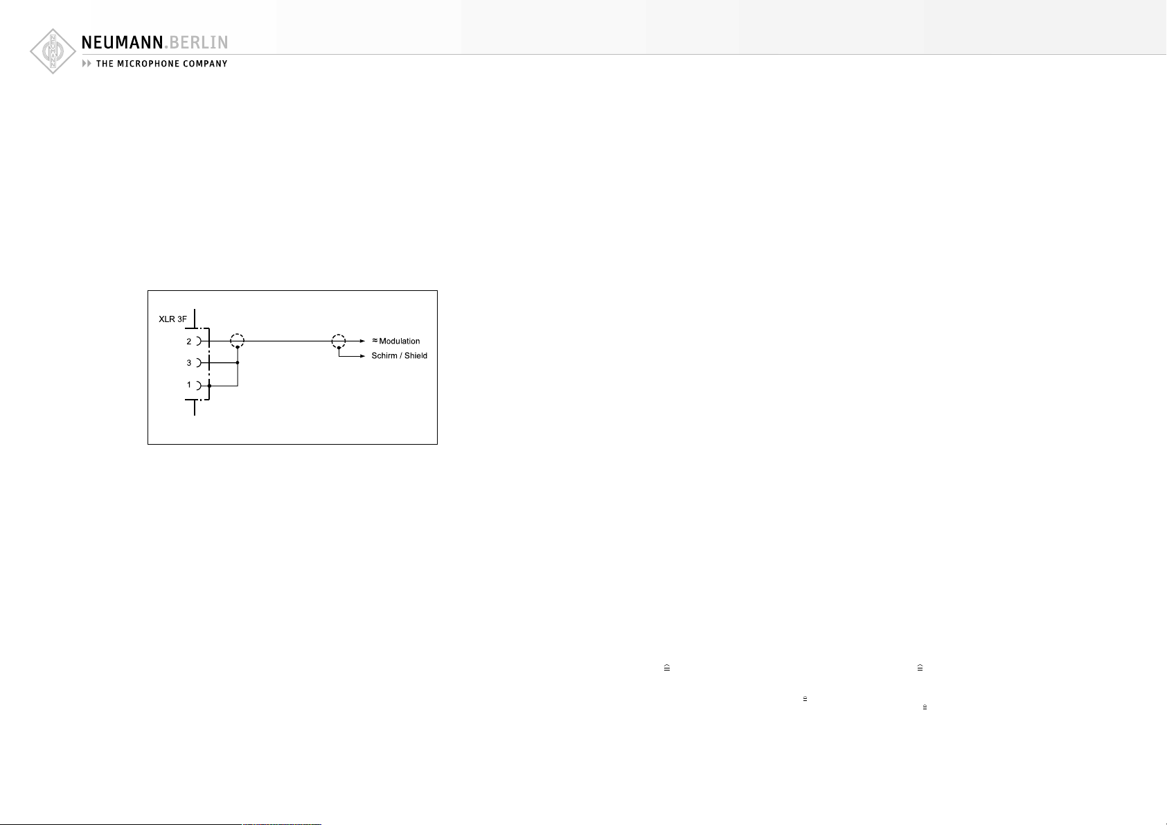
3.1 Betrieb an unsymmetrischen Eingängen
Das Netzgerät N 149 A hat einen symmetrischen,
gleichspannungsfreien Ausgang. Die Zuordnung der
Mikrophonanschlüsse entspricht DIN EN 60268-12
bzw. IEC 60268-12:
Pin 1: 0 V/Masse
Pin 2: Modulation (+Phase)
Pin 3: Modulation (–Phase)
Pin 2 ist also die „heiße Phase“, und Pin 3 muss für
unsymmetrische Eingänge an Masse gelegt werden (siehe Abbildung 1).
3.1 Operation with Unbalanced Inputs
At the N 149 A power supply unit, the audio signal is available at a balanced XLR 3 output. The
microphone is wired as per DIN EN 60268-12 or
IEC 60268-12:
Pin 1: 0 V/ground
Pin 2: audio signal (+phase)
Pin 3: audio signal (–phase)
So pin 2 is the “hot phase”, pin 3 must be connected to ground when used with unbalanced inputs
(see figure 1).
Abbildung / Figure 1
4. Technische Daten
Akust. Arbeitsweise .... Druckgradientenempfänger
Richtcharakteristik ..................................... Niere
Übertragungsbereich .................... 20 Hz...20 kHz
Feldübertragungs-
1)
faktor
........................................................... 20 mV/Pa
Nennimpedanz ....................................... 50 Ohm
Nennabschlussimpedanz ..................... 1000 Ohm
Geräuschpegelabstand
CCIR 468-3 ............................................... 70 dB
Geräuschpegelabstand
DIN/IEC 651 ............................................. 82 dB
Ersatzgeräuschpegel
CCIR 468-3 ............................................... 24 dB
Ersatzgeräuschpegel
DIN/IEC 651 .......................................... 12 dB-A
Grenzschalldruckpegel (Röhrencharakteristik)
für k < 0,5 % ........................................... 114 dB
für k < 5 % .............................................. 134 dB
Dynamikumfang des Verstärkers
DIN/IEC 651
für k < 0,5%
für k < 5% ............................................... 122 dB
Max. Ausgangsspannung ............................ 8 dBu
Stromversorgung .................... Netzgerät N 149 A
Erforderliche Steckverbinder:
Mikrophon ................. Binder 8-pol. (DIN 45326)
Netzgerät ................................................ XLR 3F
Gewicht ................................................... 460 g
Abmessungen ........................ Ø 57 mm x 142 mm
1 Pa = 10 µbar
0 dB 20 µPa
2)
................................................... 102 dB
4. Technical Specifications
Acoustical op. principle ............. Pressure gradient
Polar pattern .......................................... cardioid
Frequency range .......................... 20 Hz...20 kHz
Sensitivity
Rated impedance ................................... 50 ohms
Rated load impedance ....................... 1000 ohms
S/N ratio
CCIR 468-3 .............................................. 70 d B
S/N ratio
DIN/IEC 651 ............................................. 82 dB
Equivalent SPL
CCIR 468-3 ............................................... 24 dB
Equivalent SPL
IEC/DIN 651 .......................................... 12 dB-A
Max. SPL (tube characteristic)
for THD < 0.5 % ...................................... 114 dB
for THD < 5 % .......................................... 134 dB
Dynamic range of the amplifier
DIN/IEC 651
for THD < 0.5%
for THD < 5% ...........................................122 dB
Max. output voltage ................................... 8 dBu
Power supply .......................................... N 149 A
Required connectors:
Microphone ................ Binder 8-pin (DIN 45326)
Power supply unit .................................... XLR 3F
Weight ..................................................... 460 g
Dimensions ........................... Ø 57 mm x 142 mm
1 Pa = 10 µbar
0 dB 20 µPa
1)
................................................... 20 mV/Pa
2)
............................................. 102 dB
transducer
1)
bei 1 kHz an 1 kOhm Nennlastimpedanz. 1 Pa 94 dB SPL.
2)
Klirrfaktor des Mikrophonverstärkers bei einer Eingangsspannung, die der von der Kapsel beim entsprechenden
Schalldruck abgegebenen Spannung entspricht.
1)
at 1kHz into 1 kohm rated load impedance.
1 Pa 94 dB SPL.
2)
THD of microphone amplifier at an input voltage equivalent to
the capsule output at the specified SPL.
8 9
Page 6

M 147 Tube
5. Frequenzgänge und Polardiagramm
Frequency Responses and Polar Pattern
gemessen im freien Schallfeld nach IEC 60268-4
measured in free-field conditions (IEC 60268-4)
6. Einige Hinweise zur Pflege von
Mikrophonen
Staubschutz verwenden: Mikrophone, die nicht im
Einsatz sind, sollte man nicht auf dem Stativ einstauben lassen. Mit einem Staubschutzbeutel
(nicht fusselnd) wird dies verhindert. Wird ein Mikrophon längere Zeit nicht verwendet, sollte es
staubgeschützt bei normalem Umgebungsklima
aufbewahrt werden.
Popschutz verwenden: Ein Popschutz hat nicht nur
die Aufgabe, bei Gesangsaufnahmen die Entstehung von Poplauten zu verhindern. Er vermeidet
auch effizient, dass sich von der Feuchtigkeit des
Atems bis hin zu Essensresten unerwünschte Partikel auf der Membran ablagern.
Keine überalterten Windschutze verwenden: Auch
Schaumstoff altert. Das Material kann brüchig und
krümelig werden. Anstatt das Mikrophon zu schützen, kann er dann zur Verunreinigung der Mikrophonkapsel führen. Überalterte Windschutze also
bitte entsorgen.
Funktionstest: Moderne Kondensatormikrophone
nehmen durch lautes Ansprechen keinen Schaden.
Zur Kontrolle, ob ein solches Mikrophon angeschlossen ist, sollte man es aber keinesfalls anpusten oder anpoppen, da dies einem akustischen Signal von mehr als 140 dB (!) entsprechen kann.
Normale Sprache genügt zum Funktionstest völlig.
Selbsthilfe kann teuer sein! Leider kommt es doch
vor, dass durch eine Selbstreparatur mehr beschädigt als behoben wird. Insbesondere das Reinigen
verschmutzter Kapseln erfordert viel Erfahrung und
die Hand eines Fachmanns. Der Lackschutz auf
Platinen zeigt u.a. an, dass dort nicht gelötet werden darf. Einige Bauteile sind speziell selektiert
und können nicht durch Material von der Stange
ersetzt werden. Um unnötige Kosten zu vermeiden,
empfiehlt sich die Einsendung an unsere Vertretungen oder an uns.
Inspektion durchführen lassen: Regelmäßiges
Durchchecken des Mikrophonbestands, wie es einige Schauspielhäuser und Rundfunkanstalten
praktizieren, kann bei der Früherkennung von
Schäden helfen. Leichte Verschmutzungen lassen
sich eher beseitigen, als eine untrennbar in die
Membran eingebrannte Nikotinschicht. Insbesondere bei Mikrophonen im Verleih und in verunreinigenden Umgebungen empfiehlt sich die regelmäßige Kontrolle, deren Kosten im Vergleich zu
einer aufwendigen Reparatur sehr gering sind.
6. Hints on Microphone Maintenance
Use a dust cover: Microphones not in use should
not be left on the stand gathering dust. This can
be prevented by the use of a non-fluffy dust cover. When not in use for a longer period, the microphone should be sealed against dust and stored
under standard climatic conditions.
Use a pop screen: A pop screen not only prevents
the occurrence of plosive pop noises in vocal recordings, but also efficiently prevents unwanted
particles, from respiratory moisture to food remnants, from settling on the diaphragm.
Avoid the use of old wind shields: As the foam
material of a wind shield ages it can become brittle and crumbly. Instead of protecting the microphone, an old wind shield can thus lead to soiling
of the microphone capsule. Therefore please dispose of worn-out wind shields.
Function testing: Although modern condenser microphones are not harmed by high sound pressure
levels, one should under no circumstances use a
pop-test to check whether the microphone is connected and the channel on the mixing console is
pulled up, since this can result in sound pressure
levels of over 140 dB! Normal speech is quite sufficient for function testing.
Do-it-yourself repairs can be expensive! Unfortunately, do-it-yourself repairs sometimes do more
harm than good. Cleaning soiled capsules in particular requires considerable experience and an
expert touch. The protective lacquer on circuit
boards indicates, among other things, places
which must not be soldered. Certain components
are specially selected and cannot be replaced by
standard parts. To avoid unnecessary expense, we
recommend sending defective microphones to us
or our representatives for servicing.
Regular inspections: Sending in microphones regularly for inspection, as practiced by some theaters
and broadcasting corporations, can aid in the early detection of damage. Slight soiling can be removed much more easily than a nicotine layer inextricably bonded to the diaphragm. Regular inspections are particularly to be recommended for
microphones which are rented or are used in dusty
or smoky environments, since the costs are low in
comparison with the cost of a major overhaul.
10 11
Page 7

M 147 Tube
7. Zubehör
*)
Elastische Aufhängung
Um mechanische Erschütterung fernzuhalten, empfiehlt sich die Verwendung einer elastischen Mikrophonaufhängung.
EA 1 .................... ni ............. Best.-Nr. 08449
EA 1 mt ............... sw ............ Best.-Nr. 08450
Die EA 1 ist für die Mikrophone TLM 103, TLM 127,
TLM 193 und M 147 Tube vorgesehen. Der schwenkbare Gewindeanschluss hat 5/8"-27-Gang, mit Adapter für 1/2"- und 3/8"-Stative.
Stativgelenke und mechanische Adapter
SG 1 .................... sw ............ Best.-Nr. 08445
(gehört zum Lieferumfang)
Stativgelenk für die Mikrophone TLM 103,
TLM 127, TLM 193 und M 147 Tube. Die Halterung
des SG 1 ist aus Metall, der Gewindeanschluss hat
5/8"-27-Gang, mit Adapter für 1/2"- und 3/8"-Stative.
DS 1 20 ............... sw ............ Best.-Nr. 07343
Das DS 120 hat eine 150 mm lange Schiene, mit
zwei verschiebbaren 1/2"-Gewindeschrauben zur
Befestigung zweier Mikrophone in ihren Halterungen. Abstand und Winkel für die Anordnung der
Mikrophone sind wählbar. Der Gewindeanschluss
hat 5/8"-27-Gang, mit Adapter für 1/2"- und 3/8"Stative.
Mikrophonneigevorrichtung
MNV 87 .............. ni ............. Best.-Nr. 06804
MNV 87 mt ......... sw ............ Best.-Nr. 06806
Die Neigevorrichtung besteht aus einer Kabelhalterung und einem drehbaren 1/2"-Gewindezapfen
zum Anschluss an z.B. Stativgelenke. Das Kabel
wird in die Halterung geklemmt und dort fixiert.
Die Neigung des an seinem Kabel hängenden Mikrophons ist damit frei einstellbar.
Tisch- und Fußbodenständer
MF 3 ................... sw ............ Best.-Nr. 07321
Der Mikrophonfuß MF 3 ist ein Tischständer mit
Eisenfuß, 1,6 kg schwer, Durchmesser 110 mm. Der
7. Accessories
*)
Elastic Suspension
The use of an elastic suspension is recommended
to prevent the microphone from being exposed to
strong mechanical vibrations caused by structure
borne shock waves.
EA 1 .................... ni ............... Cat. No. 08449
EA 1 mt ............... blk ............. Cat. No. 08450
The EA 1 is designed for the TLM 103, TLM 127,
TLM 193 and M 147 Tube microphones. It has a
swivel mount with a 5/8"-27 female thread, plus
a thread adapter to connect to 1/2"- and 3/8"
stands.
Stand Mounts and Mechanical Adapter
SG 1 .................... blk ............. Cat. No. 08445
(included in the supply schedule)
Swivel mount for the TLM 103, TLM 127, TLM 193
and M 147 Tube microphones. The microphone
mount of the SG 1 is made of metal. The SG 1 has
a 5/8"-27 female thread, plus a thread adapter to
connect to 1/2"- and 3/8" stands.
DS 120 ............... blk ............. Cat. No. 07343
The DS 120 has a 150 mm long support bar with
two movable 1/2" threaded studs. Two microphones in their mounts can be attached. Any space
or angle between the microphones is freely adjustable. The DS 120 has a 5/8"-27 female thread,
plus a thread adapter to connect to 1/2"- and 3/8"
stands.
Auditorium Hanger
MNV 87 .............. ni ............... Cat. No. 06804
MNV 87 mt ......... blk ............. Cat. No. 06806
The auditorium hanger consists of a cable suspension and a rotating 1/2" threaded stud, to connect
to e. g. swivel mounts. The stud is screwed into the
threaded coupling of the swivel mount. Then the
microphone can be tilted while it is suspended
from its own cable.
Table and Floor Stands
MF 3 ................... blk ............. Cat. No. 07321
The MF 3 is a table stand with iron base, 1.6 kg in
weight, 110 mm in diameter. It has a black matte
Ständer ist schwarzmatt lackiert und steht gleitfest auf einer Moosgummischeibe. Ein umwendbarer Gewindezapfen und ein mitgeliefertes Reduzierstück ermöglichen die Verwendung für 1/2"und 3/8"-Gewindeanschlüsse.
MF 4 ................... sw ............ Best.-Nr. 07337
Der Mikrophonfuß MF 4 ist ein Fußbodenständer
aus Grauguss, ca. 2,6 kg schwer, Ø 160 mm. Der
Ständer ist schwarzmatt lackiert und steht gleitfest auf einem Gummiring. Ein umwendbarer Gewindezapfen und ein mitgeliefertes Reduzierstück
ermöglichen die Verwendung für 1/2"- und 3/8"Gewindeanschlüsse.
MF 5 ................... gr ............. Best.-Nr. 08489
Der Mikrophonfuß MF 5 hat eine graue Soft-Touch
Pulverbeschichtung und steht gleitfest und trittschalldämmend auf einem Gummiring. Der Stativanschluss hat ein 3/8"-Gewinde. Gewicht 2,7 kg,
Ø 250 mm.
STV 4 .................. sw ............ Best.-Nr. 06190
STV 20 ............... sw ............ Best.-Nr. 06187
STV 40 ............... sw ............ Best.-Nr. 06188
STV 60 ............... sw ............ Best.-Nr. 06189
Die Stativverlängerungen STV ... werden zwischen
Mikrophonständer (z.B. MF 4, MF 5) und Stativgelenk (z.B. SG 21/17 mt) geschraubt.
Die STV ... haben eine Länge von 40, 200, 400
oder 600 mm. Ø 19 mm.
Popschutz
Popschirme bieten einen sehr wirksamen Schutz
vor den sogenannten Popgeräuschen. Sie bestehen
aus einem runden, dünnen Rahmen, der beidseitig mit schwarzer Gaze bespannt ist.
Popschirme sind an einem etwa 30 cm langen
Schwanenhals montiert. Eine Klammer mit einer
Rändelschraube an dessen Ende dient der Befestigung am Mikrophonstativ.
PS 15 .................. sw ............ Best.-Nr. 08472
Der Rahmendurchmesser beträgt 15 cm.
PS 20 a ............... sw ............ Best.-Nr. 08488
Der Rahmendurchmesser beträgt 20 cm.
Schaumstoffwindschutz
Zum Vermeiden von Störgeräuschen, die bei Nahbesprechung, Windeinfluß oder z.B. bei schnellem
finish. The bottom is fitted with a non-slip rubber
disk. The stand comes with a reversible stud and
an adapter for 1/2" and 3/8" threads.
MF 4 ................... blk ............. Cat. No. 07337
Floor stand with grey cast iron base. The floor
stand has a matte black finish and rests on a nonskid rubber disk attached to the bottom. A reversible stud and a reducer for 1/2" and 3/8" threads
are also supplied. Weight 2.6 kg, Ø 160 mm.
MF 5 ................... gr ............... Cat. No. 08489
Floor stand with grey soft-touch powder coating.
It has a non-skid sound-absorbing rubber disk attached to the bottom. The stand connection has a
3/8" thread. Weight 2.7 kg, Ø 250 mm.
STV 4 .................. blk ............. Cat. No. 06190
STV 20 ............... blk ............. Cat. No. 06187
STV 40 ............... blk ............. Cat. No. 06188
STV 60 ............... blk ............. Cat. No. 06189
The STV... stand extensions are screwed between
microphone stands (for example MF 4, MF 5) and
swivel mounts (for example SG 21/17 mt).
Length 40, 200, 400 or 600 mm. Ø 19 mm.
Popscreen
Pop screens provide excellent suppression of socalled pop noise. They consist of a round, thin
frame covered with black gauze on both sides.
A gooseneck of about 30 cm (12") in length is
mounted at the popshield. It will be attached to
microphone stands by means of a clamp with a
knurled screw.
PS 15 .................. blk ............. Cat. No. 08472
The frame is 15 cm in diameter.
PS 20 a ............... blk ............. Cat. No. 08488
The frame is 20 cm in diameter.
Foam Windscreen
To protect against noise caused by wind, close
talking, and rapid movement on a boom, opencell
12 13
Page 8

M 147 Tube
Schwenken des Mikrophongalgens auftreten können, sind Windschutzeinrichtungen aus offenporigem Polyurethanschaum lieferbar. Diese Windschirme erzeugen keine störenden Resonanzen
und beeinflussen nicht die Richtcharakteristik des
Mikrophons. Das Übertragungsmaß wird im oberen
Frequenzbereich geringfügig gedämpft.
WS 87 ................. sw ............ Best.-Nr. 06753
Windschutz für U 67, U 87 (Ai), TLM 50, TLM 103,
TLM 127, M 147 Tube und TLM 170 (R). Dämpfung
des Windgeräusches 26 dB. Dämpfung bei 15 kHz
3 dB. Ø ca. 90 mm. Farbe schwarz.
*)
Weitere Artikel sind im Katalog „Zubehör“ beschrieben.
polyurethane foam windshields are available.
These windshields have no disturbing resonances and do not affect the microphone’s directional
characteristic. The frequency response is only
slightly attenuated in the higher frequency range.
WS 87 ................. blk ............. Cat. No. 06753
Windscreen for U 67, U 87 (Ai), TLM 50, TLM 103,
TLM 127, M 147 Tube and TLM 170 (R). Wind
noise attenuation 26 dB. Attenuation at 15 kHz
3 dB. Ø 90 mm. Color black.
*)
Further articles are described in the catalog “Accessories”.
IC 3 mt KT 8
N 149 A
N 149 V
AC 25
EA 1 (mt)
SG 1 DS 120
MF 3 MF 4
MNV 87 (mt)
MF 5
14 15
Page 9

PS 15 PS 20 a
STV...
WS 87
Irrtümer und technische Änderungen vorbehalten • Errors excepted, subject to changes
Printed in Germany • Publ. 03/05 74932/A04
 Loading...