

Page 1
Bedienungsanleitung
Operating Instructions
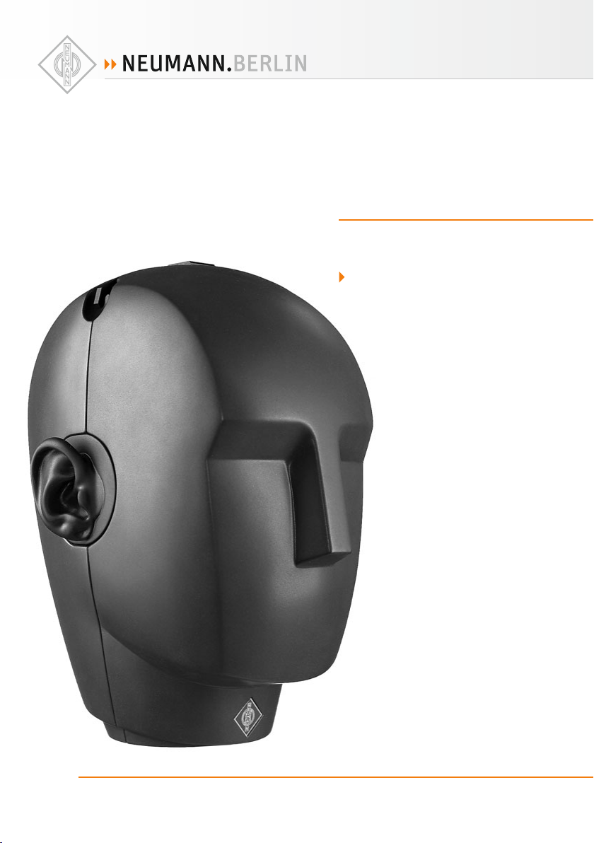
KU 100
georg neumann gmbh · ollenhauerstr. 98 · 13403 berlin · germany
tel +49 (0)30 / 41 77 24-0 · fax -50 · headoffice@neumann.com · www.neumann.com
Page 2

Inhaltsverzeichnis
1. Kurzbeschreibung
2. Der Kunstkopf KU 100
2.1 Wirkungsweise und Anwendung
2.2 Die Mikrofonausgänge
2.3 Das Öff nen des Kunstkopfes
2.4 Das schaltbare Hochpassfi lter,
der –10 dB-Schalter
2.5 Mikrofonkabel
3. Stromversorgung
3.1 Batteriespeisung
3.2 Betrieb mit externem Netzgerät
3.3 Phantomspeisung
4. Das Kalibrieren der Kunstkopfsysteme
5. Servicehinweise
6. Technische Daten
7. Frequenzgänge
8. Zubehör
Table of Contents
1. Description
2. The KU 100 Dummy Head
2.1 Principles of Operation and Applications
2.2 Microphone Outputs
2.3 The Opening of the Dummy Head
2.4 Switchable High-Pass Filter,
–10 dB Switch
2.5 Microphone Cables
3. Power Supply
3.1 Battery Operation
3.2 Operation with External Power Supply Unit
3.3 Phantom Powering
4. Calibrating the Dummy Head Systems
5. Service
6. Technical Specifi cations
7. Frequency Responses
8. Accessories
1. Kurzbeschreibung
Der Kunstkopf KU 100 ist eine besondere Art StereoMikrofon, das dem menschlichen Kopf nachgebildet
und in den Ohren mit zwei Kapseln ausgerüstet ist.
Beim Abhören mit einem hochwertigen Kopfhörer
wird die Illusion vermittelt, der Hörer befi nde sich
unmittelbar am Ort des Geschehens.
Mit der kopfbezüglichen Stereophonie, die der
Kunstkopf KU 100 bietet, wird der Hörer an den
jeweiligen Originalschauplatz versetzt, im Gegensatz
zur sonst üblichen raumbezüglichen Aufnahmetechnik, bei der das Hörereignis an den Ort des Abhörens
transportiert wird.
Aufgrund seiner Bauweise eignet sich der Kunstkopf
als Aufnahmesystem und Messmittel vor allem für
folgende Aufgaben:
• Hörspiel/Featureproduktionen
• Konzertmitschnitte und Live-Übertragungen aus
den Bereichen Klassik, Jazz, Pop und Unterhaltung
• Stereoaufnahmen ohne großen Aufwand in akustisch sehr komplexen Räumen, z. B. in Kirchen
2
1. Description
The KU 100 dummy head is a binaural stereo microphone. It resembles the human head and has
two microphone capsules built into the ears. When
listening through high-quality headphones it gives
the illusion of being right at the scene of the acoustic events.
When using the KU 100 dummy head, the binaural stereo experience moves the listener into the
scene of the original performance, in contrast to
other space-related recording techniques, where
the acoustic event is moved to the listener.
Thanks to its design, the dummy head is a suitable
means of recording and monitoring for a number of
applications, in particular:
• Radio Drama/Feature Productions
• Recording of concerts and live broadcasts in the
areas of classical music, jazz, pop music, and
entertainment shows
• Stereo recordings with relatively simple means
in acoustically very complex environments (i.e.
churches)
Page 3

KU 100
• Dokumentation von Tierstimmen und Naturbildern, von Konferenzen, Theater- und Opernaufführungen
• Einspielkontrolle in Sälen, Theatern und Auditorien
• Dokumentation und Beurteilung der Hörsamkeit
von Räumen (z. B. Konzertsälen)
• Dokumentation und Beurteilung von Musikinstrumenten
• Dokumentation und Beurteilung einer elektroakustischen Übertragungsanlage in Räumen oder
auch in Fahrzeugen (Kommunikationsanlagen,
Autolautsprecher)
• Sprachverständlichkeitsmessungen
• Dokumentation und Beurteilung der Belästigung
durch Lärm in der Industrie, am Arbeitsplatz und
im Verkehr
• Messung von (off enen) Kopfhörern
Der KU 100 kann mit 48 V-Phantomspeisung, mit einem Steckernetzteil oder mit einsetzbaren Batterien
betrieben werden. Im Bodenstück sind Anschlüsse
für symmetrischen und unsymmetrischen Betrieb
und ein Speisungsumschalter enthalten.
Im Inneren des Kopfes befi nden sich weitere Kippschalter für ein Hochpassfi lter (150 Hz, 40 Hz und
Linear) und für eine 10 dB-Vordämpfung der Empfi ndlichkeit.
2. Der Kunstkopf KU 100
2.1 Wirkungsweise und Anwendung
Der Kunstkopf KU 100 ist in seinen Abmessungen
dem menschlichen Kopf nachgebildet und anstelle
der beiden Gehörorgane mit Mikrofonen ausgerüstet.
Beim Abhören des Kunstkopfsignals mit einem hochwertigen, diff usfeldentzerrten Kopfhörer entsteht
ein Höreindruck, der fast vollständig demjenigen
gleicht, den der Hörer bei stillgehaltenem Kopf am
Ort des Kunstkopfes gewinnen würde und vermittelt daher die Illusion des Dabeiseins am Ort der
Darbietung.
Das Klangbild bei Lautsprecherwiedergabe entspricht weitgehend dem, das ein herkömmliches
Stereomikrofon am Ort des Kunstkopfes übertragen
würde, jedoch mit diff erenzierterer Abbildung der
Raumtiefe.
• Documentation of animal voices and natural
sounds, conferences, theater and opera performances
• Monitoring of the eff ect of PA systems in halls,
theaters, and auditoriums
• Documentation and assessment of the audibility
conditions of rooms (i.e. concert halls)
• Documentation and assessment of musical instruments
• Documentation and assessment of electroacoustic PA systems in rooms and/or in automobiles
(i.e. evaluation of automotive loudspeakers)
• Measurement of speech intelligibility
• Documentation and assessment of noise nuisance
in industry, at workplaces or in traffi c
• Measurement of (open) headphones
The KU 100 can be operated with typical 48 V
phantom powering, or from an external power supply unit, or from the built-in battery. At the bottom
of the unit is a switch for the diff erent power supply modes, as well as connectors for balanced and
unbalanced output signals.
Inside the head are additional fl ip switches for 10 dB
attenuation and the high-pass fi lter (150 Hz, 40 Hz,
and linear).
2. KU 100 Dummy Head
2.1 Principles of Operation and Applications
The KU 100 dummy head is a replica dimension wise
of the human head, equipped with microphones in
place of the ears. Listening to the dummy head
signals through high-quality, diff use-fi eld equalized headphones, the listener receives an impression which is almost completely identical to that
which he or she would have when keeping the head
stationary at the location of the dummy head, i.e.
the illusion of physical presence at the scene of the
performance.
lf reproduced through loudspeakers, the sound
impressions are almost identical to those obtained
by means of conventional stereo microphone techniques with an increased sense of “depth” of the
sound-stage.
3
Page 4

Für kreative Hörspielgestaltung ist der Kunstkopf
ebenso gut geeignet wie beispielsweise für Musikaufnahmen, wobei der Vorteil gegenüber herkömmlicher Aufnahmetechnik in der getreuen Übertragung
der Raumakustik liegt. Der KU 100 wird aber auch
zur Untersuchung von Lärmeinfl üssen an verschiedensten Arbeitsplätzen unter wirklichkeitsgetreuen
Bedingungen eingesetzt. Dabei wird das Schallfeld
physiologisch richtig erfasst, kann aufgezeichnet
und bei Bedarf erst später – evtl. von mehreren
Versuchs personen unter denselben Hörbedingungen
– aus gewertet werden.
Der KU 100 stellt bereits die dritte Generation des
Neumann-Kunstkopfes dar. Während der Schritt vom
ersten Studio-Kunstkopf, dem KU 80, zum KU 81
der Übergang von der Freifeldentzerrung zur Diffusfeldentzerrung war und damit die Lautsprecherkompatibilität der Kunstkopfsignale sicherstellte,
werden im Kunstkopf KU 100 folgende technische
Verbesserungen angeboten:
For artistic recordings, the KU 100 is equally suited
for creative radio drama recordings and for music
presentations, the advantage of the KU 100 over
conventional stereo recording techniques being a
more realistic representation of the acoustic conditions in the recording environment. In industrial
applications, the KU 100 can be utilized to assess
noise infl uences at diff erent workplaces under realistic conditions. The sound fi eld is received in a
physiologically proper manner and can be recorded
for subsequent eva luation by diff erent test subjects
under the same listening conditions.
The KU 100 represents the third generation of the
Neumann artifi cial head stereo microphone systems
(dummy head). The original KU 80 was replaced by
the KU 81 which marked the transition from “freefi eld” equalization to “diff use-fi eld” equalization.
This yielded compatibility of the dummy head
signals with stereo loudspeaker reproduction. The
KU 100 replaces the KU 81 and off ers the following
advancements:
Akustische Verbesserungen
• Überarbeitung der Außenohren für exakte Symmetrie der Charakteristika links/rechts
• noch bessere Annäherung an das Ideal „ebener
Diff usfeldfrequenzgang“
• Korrektur der Ohrkoordinaten zur Vermeidung
einer Elevation der Schallquellen im Hörereignis
Schaltungstechnische Verbesserungen
• Transformatorlose Schaltungstechnik „fet 100“
• Erhöhung des Übertragungsmaßes um 5 dB
• Erweiterung des Dynamikumfangs um 5 dB
Verbesserte Handhabung
• Mehrfache Stromversorgungsmöglichkeit:
- Eingebaute Batteriespeisung mit Kontroll-LED
„Low Batt.“
- externe Phantomspeisung P48 durch 5-poligen
XLR-Stecker
- Versorgung aus mitgeliefertem Steckernetzge-
rät möglich
Acoustic lmprovements
• Revised design of the outer ears for precise symmetry of the left/right characteristics
• Improved approximation of the ideal “smooth
diff use-fi eld frequency response”
• Adjusted ear coordinates, thereby avoiding vertical displacements of sound sources (artifi cial
elevations) in the listening event
Improved Circuitry
• Transformerless “fet 100” circuit
• Sensitivity increased by 5 dB
• Dynamic range increased by 5 dB
Improved Flexibility
• Flexible power supply confi gurations:
- Integrated battery supply with LED “low bat-
tery power”
- external P48 phantom powering via 5-pin XLR
connection
- powering via supplied external power supply
unit
4
Page 5

KU 100
• Alternative Ausgangsbeschaltung:
- Symmetrische XLR-Ausgänge für Studiobetr ieb
und getrennte links/rechts BNC-Ausgänge für
unsymmetrische Mess-, Daten-und Speichergeräte eingebaut
• Schaltbares Hochpassfi lter (150 Hz, 40 Hz und
Linear)
• Schaltbare 10 dB-Dämpfung
Gerade wegen der aufgeführten Verbesserungen
haben die grundsätzlichen Veröff entlichungen über
das Arbeiten mit dem Kunstkopf, die in der beiliegenden Dokumentation zusammengestellt sind,
weiterhin Gültigkeit.
Sie sollen zeigen, wo der Kunstkopf als Aufnahmesystem und Messmittel bisher mit Erfolg eingesetzt
wurde und warum er sich für die im folgenden aufgeführten Aufgaben z.T. besser eignet als „normale“
Stereomikrofonanordnungen oder Messmikrofone:
Der Kunstkopf ist das Anfangsglied einer Übertragungskette in „Kopfbezogener Stereophonie“. Am
anderen Ende sollten hochwertige diffusfeldentzerrte Kopfhörer stehen. Deshalb wird in der beiliegenden Literaturauswahl auch auf die optimale
Kopfhörerentzerrung bzw. auf entsprechend konstruierte Kopfhörer eingegangen.
2.2 Die Mikrofonausgänge
Der Kunstkopf KU 100 besitzt symmetrische und
unsymmetrische transformatorlose Ausgänge.
• Flexible output connector confi gurations:
- Integrated, balanced XLR outputs for studiooperation as well as separate Left/Right BNC
outputs for unbalanced measuring, data processing and data storage devices
• Switchable high-pass fi lter (150 Hz, 40 Hz and
linear)
• Switchable 10 dB attenuation
Especially because of the above-mentioned improvements, the general publications concerning
the use of the dummy head, which are compiled in
the enclosed documentation, remain in full eff ect.
Their purpose is to describe applications in which
the dummy head as a recording system and measuring instrument has been successfully used so far,
and why it is sometimes more suitable than “normal” stereo microphone arrangements or measuring
microphones for the applications described below:
The dummy head is the fi rst link of the transmission
chain in “Head-Related Stereophony”. High-quality,
diff use-fi eld equalized headphones should be on the
other end. This is why the enclosed literature also
refers to the subject of optimal headphone equalization as well as suitable designed headphones.
2.2 Microphone Outputs
The KU 100 dummy head is provided with balanced
and unbalanced, transformerless outputs.
Der symmetrische Ausgang
Der symmetrische 5-polige XLR-Ausgang hat folgende Belegung gemäß DIN EN 60268-12 bzw.
IEC 60268-12:
Pin 1: 0 V/Masse
Pin 2 (+):
Pin 3:
Pin 4 (+):
Pin 5:
Über diesen symmetrischen Ausgang kann der Kunstkopf KU 100 mit 48 V, 3,5 mA pro Kanal phantomgespeist werden (s. Kapitel 3.3 „Phantomspeisung“).
Es müssen stets beide Kanäle gespeist werden.
(+) p ositiver S pannungsa nstieg bei ei nem Schalld ruckan-
Modulation linker Kanal
Modulation rechter Kanal
stieg v or dem jeweili gen Ohr
Balanced Output
The balanced 5-pin XLR output features the following pin assignments according to DIN EN 60268-12
and/or IEC 60268-12:
Pin 1: 0 V/ground
Pin 2 (+):
Pin 3:
Pin 4 (+):
Pin 5:
This balanced output also permits phantom powering of the KU 100 dummy head with 48 V, 3.5 mA,
each channel, (see chapter 3.3: “Phantom, powering”). Both channels always have to be powered.
(+) po lar ity at a sudd en ris e of so und p ress ure in f ront of the
modulation left channel
modulation right channel
respective ear
5
Page 6

Es muss beachtet werden, dass an diesem Ausgang auch bei Speisung aus Batterien oder aus
dem externen Steckernetzgerät die 48 V-Phantomspeisung anliegt, die intern erzeugt wird.
Daher müssen spezielle Kabel verwendet werden,
falls der XLR-Ausgang für unsymmetrische Eingänge
benutzt werden soll (s. Kapitel 2.5 „Mikrofonkabel“).
Der 5-polige XLR-Ausgang kann mit Hilfe des zum
Lieferumfang gehörigen Adapterkabels AC 20 auf
zwei 3-polige XLR-Stecker aufgelöst werden und
passt dann auf in der Studiotechnik übliche (phantomgespeiste) Mikrofoneingänge (s. Kapitel 2.5
„Mikrofonkabel“).
Note that the 48 V phantom power, which is generated internally, is present at the output even
if power is obtained via the internal batteries or
via the external power supply unit.
Special cables are hence necessary if the XLR output
has to be used for unbalanced inputs (see chapter
2.5: “Microphone cable”).
The 5-pin XLR output can be distributed to two 3-pin
XLR connectors by means of the AC 20 adapter cable
supplied and then matches the common (phantompowered) microphone inputs for studio applications
(see chapter 2.5: “Microphone cable”).
Die unsymmetrischen Ausgänge
Für den Betrieb an unsymmetrischen Eingängen
(DAT-Recorder, Messgeräte etc.) stehen die Ausgangssignale gleichspannungsfrei an zwei BNCBuchsen, beschriftet mit L für den linken Kanal und
R für den rechten Kanal, zur Verfügung.
Bei Verwendung dieser Ausgänge wird der KU 100
entweder intern mit Batterien oder extern mit dem
beiliegenden Steckernetzteil gespeist. Siehe dazu
Kapitel 2.3 „Das Öff nen des Kunstkopfes“, Kapitel
3.1 „Batteriespeisung“ und Kapitel 3.2. „Betrieb mit
externem Netzgerät.
Durch spezielle Adapterkabel (separat lieferbares
Zubehör) kann der Kunstkopf auch unter Verwendung des 5-poligen XLR-Ausgangs auf unsymmetrische Klinkeneingänge geschaltet werden. Siehe
Kapitel 2.5 „Mikrofonkabel“.
2.3 Das Öff nen des Kunstkopfes
Zum Einlegen bzw. Austauschen von Batterien bei
netzunabhängiger Speisung, zum Bedienen des
schaltbaren Hochpassfi lter oder der 10 dB-Dämpfung
oder für eventuelle Reparaturarbeiten muss der
Kunstkopf geöff net werden.
Dieses geschieht mit Hilfe der beiden Vierteldrehverschlüsse am Hinterkopf. Sie werden durch jeweils
eine Viertel-Linksdrehung entriegelt. Dann kann die
hintere Kopfhälfte (ohne Ohren) parallel nach hinten
abgezogen werden, während die vordere Kopfhälfte
z.B. auf dem Stativ etc. verbleiben kann.
Nach dem Öff nen des Kunstkopfes werden die Batteriehalterung, die Ohrsysteme und das Gehäuse der
Ausgangsstufe sichtbar.
Unbalanced Outputs
The output signals are also available dc-free at two
female BNC connectors (marked “L” and “R” for left
and right respectively) for operation in conjunction
with unbalanced inputs, (i.e. DAT recorders, measurement instruments, etc.).
When the engineer is utilizing the unbalanced outputs, the required phantom power can be obtained
either via internal batteries or via the external
power supply. See chapter 2.3: “Opening the dummy
head”, chapter 3.1: “Battery supply”, and chapter
3.2: “Operation with external power supply unit“.
By means of special adapter cables (separately
available accessories) the dummy head can also
be connected to unbalanced jack-plug inputs. See
chapter 2.5: “Microphone Cables”.
2.3 Opening the Dummy Head
The KU 100 dummy head can be opened to access
the batteries for mains-independent power supply,
to operate the switchable high-pass fi lter or the
10 dB attenuation unit, or whenever any service
work has to be done.
This is done by means of the two 90° lock fasteners
at the back of the head which are unlocked by turning them counter-clockwise. The back of the head
(without the ears) can then be pulled off leaving
the front which can be left in place, e.g. on a microphone stand.
The battery holder, the ear systems, and the output
stage are visible after opening the dummy head.
6
Page 7

KU 100
Der Zusammenbau erfolgt sinngemäß umgekehrt
durch Aufschieben des Hinterkopfes mit anschließendem Verriegeln durch Rechtsdrehung der beiden
Vierteldrehverschlüsse, bis die Knäufe waagerecht
positioniert sind.
2.4 Das schaltbare Hochpassfi lter,
der –10 dB-Schalter
Nach dem Öff nen des Kunstkopfes (s. Kapitel 2.3)
werden an der Oberseite der Ausgangsstufe zwei
Kippschalter zugänglich:
Links der 3-stufi ge Schalter für verschiedene Grenzfrequenzen eines Hochpassfi lters, rechts der –10 dBSchalter zur Reduzierung des Übertragungsmaßes.
Beide Schalter wirken jeweils auf beide Kanäle.
Die –3 dB-Grenzfrequenzen des Hochpassfi lters sind:
8 Hz in Schalterstellung LIN, 40 Hz und 150 Hz. Da-
durch lassen sich tieff requente Störungen wie z.B.
Körperschall ausblenden.
2.5 Mikrofonkabel
Der symmetrische Anschluss des Kunstkopfes
KU 100 erfolgt über das beigelegte 5-polige geschirmte Mikrofonkabel IC 5.
Mit Hilfe des ebenfalls zum Lieferumfang gehörenden Adapterkabels AC 20 kann die 5-polige XLRArmatur auf zwei 3-polige XLR-Stecker aufgelöst
werden und passt dann auf in der Studiotechnik
übliche (phantomgespeiste) Mikrofoneingänge.
Die Kabelfarbe gelb des Adapterkabels AC 20 bezeichnet den linken Kanal, die Farbe rot den rechten
Kanal.
Die 3-poligen Stecker XLR 3 M sind entsprechend
DIN EN 60268-12 bzw. IEC 60268-12 beschaltet:
Jeweils
Pin 1: 0 V/Masse
Pin 2 (+): Modulation für symmetrische
Pin 3: Eingänge
Als separates Zubehör ist das Adapterkabel AC 29
lieferbar. Mit ihm kann der 5-polige XLR-Stecker des
Kunstkopfes auf unsymmetrische Eingänge von z.B.
DAT-Recordern adaptiert werden.
For reassembly, proceed in inverse order: fi rst fi x
the back of the head in place and lock by turning
the lock fasteners until the knobs are in a horizontal
posi tion.
2.4 Switchable High-Pass Filter,
–10 dB Switch
After opening the dummy head, (see chapter 2.3)
two fl ip switches are accessible on top of the output stage:
On the left-hand side is a 3-position switch for
diff erent corner frequencies of a high-pass fi lter.
The –10 dB pad switch is on the right.
Each switch infl uences both channels.
The –3 dB corner frequencies of the high-pass fi lter are:
8 Hz in the LIN position, 40 Hz, and 150 Hz. This
feature permits elimination of low-frequency interferences, such as structure-borne noise.
2.5 Microphone Cable
Balanced connection to the KU 100 dummy head is
possible via the shielded, 5-conductor microphone
cable IC 5 (supplied).
The 5-pin XLR fi tting can be distributed to two 3-pin
XLR connectors by means of the AC 20 adapter cable
(supplied) and then matches the common (phantompowered) microphone inputs for studio applications.
The yellow cable of the AC 20 adapter cable is for
the left channel, the red cable for the right channel.
The 3-pin XLR 3 male connectors are wired according to DIN EN 60268-12 and/or IEC 60268-12:
Each
Pin 1: 0 V/ground
Pin 2 (+):
Pin 3:
The AC 29 adapter cable is available as separate
accessory. It facilitates connection of the 5-pin XLR
connector of the dummy head to unbalanced inputs,
e.g. of DAT recorders.
modulation for balanced inputs
(+) p ositiver S pannungsa nstieg bei ei nem Schalld ruckan-
stieg v or dem jeweili gen Ohr
(+) po lar ity at a sudd en ris e of so und p ress ure in f ront of the
respective ear
7
Page 8

Das Kabel AC 29 führt die Modulation auf zwei
6,3 mm Ø Monoklinkenstecker. Das Kabel hat
RC-Glieder eingebaut, um die am 5-poligen XLRAusgang des KU 100 anstehende Gleichspannung
abzublocken.
Eine Verlängerung des 5-poligen Kabels ist mit
weiteren Kabeln vom Typ IC 5 (separates Zubehör)
möglich. Standardlänge ist jeweils 10 m.
Die 3-poligen XLR-Stecker des AC 20 können mit
zwei 10 m langen Kabeln IC 3 (3-polig XLR, separates
Zubehör) verlängert werden.
Andere Kabellängen und/oder Kabelmaterial ohne
Armaturen sind auf Wunsch lieferbar.
Die akustischen Eigenschaften des Kunstkopfes werden auch durch sehr lange (Neumann-)Kabel nicht
beeinfl usst. Erst bei einer Kabellänge deutlich über
300 m macht sich ein Abfall im oberen Frequenzbereich bemerkbar.
The AC 29 cable routes the modulation to two mono
1/4" type jack-plug connectors, 6.3 mm. The cable
is provided with integrated RC elements in order
to ward off the dc voltage which is available at the
5-pin XLR output of the KU 100.
The 5-pin cable can be extended by means of additional cables, type IC 5 (separate accessories). The
standard length is 10 meters.
The 3-pin XLR connectors of the AC 20 can be extended by means of two 10 meter IC 3 cables (3-pin
XLR, separate accessories).
Cables of diff erent length and/or cables without fi ttings are available on request.
The acoustic properties of the dummy head are not
aff ected by extra-long (Neumann) cables. lt is only
with cable lengths well in excess of 300 meters that
fall-off in the higher frequency range may become
noticeable.
3. Stromversorgung
Der Kunstkopf ist ca. 10 s nach dem Einschalten der
Stromversorgung betriebsbereit. Er kann aus drei
unterschiedlichen Quellen gespeist werden:
3.1 Batteriespeisung
Zum Einlegen der Batterien den Kunstkopf mit den
beiden Vierteldrehverschlüssen am Hinterkopf entriegeln und auseinanderziehen. Im oberen Kopfteil
befi ndet sich eine herausnehmbare Halterung für
sechs Batterien vom Typ LR 67 Größe AA („Mignon“),
je 1,5 V. Zu empfehlen ist die Verwendung hochwertiger Alkali-Mangan-Batterien, die aus Sicherheitsgründen während langer Betriebspausen aus dem
KU 100 entfernt werden sollten. Dafür kann der Batterieanschluss (Druckknopfkontakte) abgezogen und
die gesamte Halterung herausgenommen werden.
Zur Batteriespeisung muss der Kippschalter an der
Kopfunterseite auf „BATT.“ geschaltet sein.
Mit frischen Batterien ist ein Dauerbetrieb von mindestens 10 Stunden möglich1).
Etwa eine Stunde bevor die Batterien die Stromversorgung nicht mehr sicherstellen können, beginnt die
rote Leuchtdiode „Low Batt.“, die sich am hinteren
Halsansatz befi ndet, zu blinken. Die Leuchtdiode
1)
B ei Zimmerte mperatur erh öht. Da die Ka pazität von B at-
terien sehr temperaturabhängig ist, verändert sich die
Betriebsdauer bei geringerer oder höherer Temperatur.
3. Power Supply
The dummy head is ready for operation approx.
10 seconds after power-up. lt can be powered from
three diff erent sources:
3.1 Battery Operation
The KU 100 can be powered by six batteries, type
LR 6, size AA (“round cells”) of 1.5 V each. A removable holder is located in the upper portion of the
head. In order to install the batteries, unlock the
dummy head at the two 90° lock fasteners at the
back of the head, and pull the two halves apart. We
recommend the use of high-quality alkali-manganese batteries which should be removed from the
KU 100 for safety reasons whenever it will not be
used for prolonged periods. Removal of the complete battery holder is accomplished by pulling off
the battery connections (snap contacts).
The fl ip switch at the bottom of the head must be
set to “BATT.” for battery operation.
New batteries will power the dummy head for at
least 10 hours1).
The red LED “Low Batt.” indicator at the neck starts
fl ashing approx. one hour before the battery power
supply will fail. The LED also fl ashes briefl y during
1)
At n ormal room te mperature s. The batt ery capac ity will
be signi cantly di erent with lower/higher ambient
temperatures.
8
Page 9

KU 100
blinkt auch beim Einschalten kurz auf, bleibt dann
aber bei ausreichender Batteriekapazität während
des Betriebs dunkel.
3.2 Betrieb mit externem Netzgerät
Zum Betrieb des Kunstkopfes KU 100 mit dem zum
Lieferumfang gehörenden Steckernetzgerät muss
der Kippschalter an der Kopfunterseite auf „EXT.“
geschaltet werden. Das Steckernetzgerät wird mit
dem 2-poligen Einbaustecker „EXT.“ verbunden und
verschraubt.
Der Kunstkopf wird mit 9 V Gleichstrom vom Steckernetzgerät gespeist. Der erlaubte Arbeitsbereich
ist +7 V ... +26 V. (Für Servicezwecke: der linke Pin
des Einbausteckers ist bei Draufsicht von außen die
Plusleitung, der rechte Pin ist 0 V, Masse. Im Gegenstecker ist die Plusleitung mit Pin 1 bezeichnet, Pin 2
ist 0 V, Masse).
Der erforderliche Steckverbinder: Fa. Binder, Serie
711, Herst.-Bez. 99 0072 100 02.
3.3 Phantomspeisung
Über die symmetrischen Ausgänge des 5-poligen
XLR-Steckers bzw. über die beiden 3-poligen XLRStecker des Adapterkabels AC 20 kann der Kunstkopf
KU 100 phantomgespeist werden (P48, IEC 61938).
Es müssen stets beide Kanäle mit 48 V, je 3,5 mA
gespeist werden.
Der Kippschalter an der Kopfunterseite muss auf
„P48“ geschaltet werden.
Bei der Phantomspeisung fl ießt der Speisestrom
jeweils vom positiven Pol der Spannungsquelle
(Mischpult oder Netzgerät) über die elektrische Mitte
der beiden Modulationsadern zum Mikrofon. Er wird
hierzu über zwei gleich große Widerstände bei den
Tonadern gleich sinnig zugeführt.
Die Rückleitung des Gleichstroms erfolgt über den
Kabelschirm. Zwischen beiden Modulationsadern
besteht also keine Potentialdiff erenz.
Für die Stromversorgung sind alle P48-Netzgeräte
geeignet, die mindestens 3,5 mA je Kanal abgeben.
Das entsprechende Neumann P48-Netzgerät hat die
Bezeichnung N 48 i-2.
Die Zuordnung der Mikrofonanschlüsse und die
Polarität der Modulationsadern ist am Ausgang der
Speisegeräte die gleiche wie am Mikrofon.
power-up, but remains dark subsequently as long as
the battery capacity is suffi cient.
3.2 Operation with External Power Supply Unit
Operation of the KU 100 dummy head with the
power supply unit supplied requires the fl ip switch
at the bottom of the head to be set to “EXT.”. The
power supply unit is connected to the integrated
2-pin “EXT.” connector and secured by means of a
coupling ring.
The dummy head requires a dc current of nominally
9 V. The permissible operating range is +7 V to +26 V.
(For service purposes: when seen from outside, the
left pin of the integrated connector is the positive
pole, the right pin being 0 V, ground. The positive
pole of the mating connector is marked “Pin 1”, pin 2
being 0 V, ground).
The matching connector: Binder Company, Series
711, Manufacturer Part No: 99 0072 100 02.
3.3 Phantom powering
Phantom powering of the KU 100 dummy head is
possible (P48, IEC 61938) via the symmetrical outputs of the 5-pin XLR connectors and/or via the two
3-pin XLR connectors of the AC 20 adapter cable.
Both channels in any case require a supply of 48 V,
3.5 mA each.
The fl ip switch at the bottom of the head must be
set to “P48”.
With phantom powering, the feeding current fl ows
from the positive pole of the voltage source (mixing
console or power supply unit), through the electrical center of the two modulation wires to the microphone. The supply current is fed into the two
audio wires in the same direction via two identically
resistors.
The dc return is via the cable shield. This means that
there is no diff erence in potentials between the two
modulation wires.
Any P48 power supply unit supplying at least 3.5 mA
per channel is suitable for power supply purposes.
The corresponding Neumann P48 power supply unit
is the model N 48 i-2.
The assignment of the microphone connections and
the polarity of the modulation wires are the same
at the output of the power supply unit and at the
microphone.
9
Page 10

4. Das Kalibrieren der Kunstkopfsysteme
Die beiden Kunstkopfsysteme „Links“ und „Rechts“
können einzeln kalibriert werden.
Mit Hilfe eines Pistonphonadapters lassen sich Kalibratoren für 1"-Messmikrofonkapseln (z.B. Bruel
& Kjaer Typ 4230 oder Typ 4228) von außen in den
jeweiligen Ohrkanalansatz stecken und beaufschlagen diesen mit einem defi nierten Schalldruckpegel.
Dann kann entweder der Ausgangspegel nur des
Kunstkopfes oder des gesamten Aufnahmesystems
gemessen und notiert werden.
4. Calibrating the Dummy Head Systems
The two microphone systems on the “left” and on
the “right” can be calibrated separately.
A pistonphone adapter permits calibrators for
1" measuring microphone capsules (e.g. Bruel &
Kjaer, type 4230 or type 4228) to be inserted from
outside into the respective ear channel outlet. The
calibrators then expose the microphone capsules to
a defi ned sound pressure level. lt is then possible
to measure and record the output level either of the
dummy head only or of the entire recording system.
5. Servicehinweise
Zum normalen Gebrauch muss der Kunstkopf nur
zum Einlegen bzw. zum Wechseln der Batterien
oder zum Betätigen des Hochpassfi lters oder des
Dämpfungsschalters geöff net werden. Siehe dazu
Kapitel 2.3.
Für Servicearbeiten ist eventuell ein Öff nen auch
des Ohrsystems und der Ausgangsstufe erforderlich.
Das Ohrsystem besteht aus den beiden Außen ohren
und dem zylindrischen Gehäuse zwischen den Ohren. Dieses ist jeweils neben den Außenohren im
Vorderkopf eingeschnappt und kann komplett herausgehoben werden.
Die Außenohren sind auf das zylindrische Gehäuse
aufgeschnappt und lassen sich ohne Werkzeug abziehen. Dann werden die Ohradapter mit dem Ohrkanal frei. Sie können jeweils von den zylindrischen
Gehäuserohren und diese ihrerseits vom mittleren
Vierkant abgeschraubt werden, so dass die Platine
mit den Impedanzwandlern (IC 101, IC 102) und
Filterstufen zugänglich wird.
Achtung:
Auf keinen Fall darf mit dem Finger auf die Ga-
belkontakte und auf die übrigen anderen hochohmigen Teile in diesem Bereich gefasst werden,
da geringste Schmutz und Fettrückstände die
Isolation herabsetzen und Störspannungen verursachen können.
In den Ohradaptern befi ndet sich jeweils die Kondensatormikrofonkapsel und ein akustisches Anpassfi lter. Diese Ohradapter – obwohl aus mehreren Teilen zusammengesetzt – sollten als Einheit
behandelt und im Falle eines Defekts komplett zur
Reparatur ins Werk eingeschickt werden.
5. Service Information
Opening of the dummy head is only required when
installing or replacing the batteries or operating the
high-pass fi lters or attenuation switch. See chapter
2.3.
Service work may require also opening of the ear
system and/or the output stage.
The ear system consists of the two outer ears and
the cylindrical enclosure between the ears. This
enclosure is snap-fastened beside the outer ears in
the front portion of the head and can be removed
completely.
The outer ears are snap-fastened on the cylindrical
enclosure and can be pulled off without any additional tools. The ear adapters and the ear channels
are then accessible. They can be detached from the
cylindrical enclosure tubes which subsequently
will unscrew from the central square, whereupon
the board with the impedance converters (IC 101,
IC 102) and fi lter stages becomes accessible.
Note:
You should never touch the forked contact at the
face of the board with your fi ngers, nor should
you touch the other extremely high-impedance
parts in this area as even the slightest dirt and
grease residues will reduce the insulation and
cause noise.
Each ear adapter contains the condenser microphone capsule and an acoustic impedance transforming fi lter. Although these ear adapters consist
of several parts, they should be treated as a unit
and sent as such to the manufacturer if additional
work is necessary.
10
Page 11

KU 100
Da beide Ohradapter im Werk auf gleiche Übertragungsmaße ausgesucht werden, ist darüber hinaus
zu empfehlen, bei einem Defekt jeweils beide Ohradapter einzuschicken.
Beim Zusammensetzen der Teile ist darauf zu achten, dass
• die Kontaktstifte der Mikrofonkapseln korrekt in
den jeweiligen Gabelkontakt an den Stirnseiten
der Platine eingeführt werden,
• die richtigen Außenohren entsprechend der
Gravur L, R (für links und rechts) auf dem Mittelteil auf die Ohradapter aufgeschnappt werden,
• das Zuführungskabel im Stauraum unter dem
zylindrischen Gehäuse verstaut wird und dafür
der Kabelaustritt aus dem Vierkant-Mittelteil nach
unten in den Stauraum zeigt,
• das Anschlusskabel zur Batteriehalterung ober-
halb des zylindrischen Gehäuses verläuft, damit
der Batteriesatz bequem herausgenommen werden kann.
Das viereckige Gehäuse der Ausgangsstufe kann aus
dem Vorderkopf herausgenommen werden, wenn die
beiden Befestigungsschrauben entfernt worden sind.
Um das Gehäuse zu öffnen, muss erst die obere
Platte abgeschraubt und herausgehoben werden.
Anschließend kann die untere Platte mit den Steckverbindern etc. abgeschraubt und mitsamt dem
kompletten Innenaufbau vorsichtig herausgezogen
werden.
Both ear adapters are carefully matched by the manufacturer in all relevant characteristics. Therefore
both ear adapters should be returned to the factory
whenever any repair work is necessary.
When assembling the parts, please ensure that:
• the contact pins of the microphone capsules
are properly inserted into the respective forked
contact at the face of the board,
• the proper outer ears are snapped onto the ear
adapters as indicated by the marks L (left) and R
(right) on the central part,
• the incoming cable is stored in the cable space
below the cylindrical enclosure, with the cable
outlet of the central square pointing downwards
to the cable space,
• the connecting cable leading to the battery holder
runs above the cylindrical enclosure, so that the
batteries can be removed without any problems.
The square enclosure of the output stage can be removed from the front portion of the head after the
two fi xing screws have been removed.
In order to open the enclosure, fi rst remove the
screws of the upper board (rear panel) and detach
it. Thereafter, the lower board (front panel) including the plug connectors etc. can be unscrewed and
pulled out carefully, together with the complete
internal components.
11
Page 12

6. Technische Daten
Akustische Arbeitsweise ............. Druckempfänger
Richtcharakteristik ........................................ Ohr
Übertragungsbereich .....................20 Hz...20 kHz
Feldübertragungsfaktor
Nennimpedanz
symmetrischer Ausgang ...........................50 Ohm
unsymmetrischer Ausgang .....................200 Ohm
Nennlastimpedanz ...............................1000 Ohm
Geräuschpegelabstand2), CCIR3) .................. 65 dB
Geräuschpegelabstand2), A-bewertet3) ......... 78 dB
Ersatzgeräuschpegel, CCIR3) .......................29 dB
Ersatzgeräuschpegel, A-bewertet3) ..........16 dB-A
Grenzschalldruckpegel für
0,5 % Klirrfaktor4) ....................................135 dB
0,5 % Klirrfaktor mit Vordämpfung4) ..........145 dB
Max. Ausgangsspannung ............................. 8 dBu
Erforderlicher Steckverbinder ......... XLR3F/XLR5F
Stromversorgung (alternativ)
Speisespannung5) ................................48 V ± 4 V
Stromaufnahme pro Kanal5) ....................... 3,5 mA
Batteriespeisung ............6 x 1,5 V (AA), „Mignon“
Externe Speisung mit Stecker-
netzteil (im Lieferumfang) .............................. 9 V
Gewicht
KU 100 ohne Batterien ........................ca. 3500 g
mit Tragekoff er ....................................ca. 9500 g
Abmessungen (B x H x T)
KU 100 ............................... 180 x 280 x 220 mm
Tragekoff er .......................... 390 x 360 x 260 mm
1)
....................... 20 mV/Pa
6. Technical Specifi cations
Acoustical op. principle ......... pressure transducer
Polar pattern .................................................. Ear
Frequency range ............................20 Hz...20 kHz
Sensitivity
Rated impedance
symmetrical output ................................50 ohms
unsymmetrical output ...........................200 ohms
Rated load impedance ........................1000 ohms
Signal-to-noise ratio2), CCIR3) ......................65 dB
Signal-to-noise ratio2), A-weighted3) .............78 dB
Equivalent noise level, CCIR3) ...................... 23 dB
Equivalent noise level, A-weighted3) ........16 dB-A
Maximum SPL
for 0.5 % THD4) .......................................135 dB
for 0.5 % THD with preattenuation4) .........145 dB
Max. output voltage .................................... 8 dBu
Matching Connector ........................ XLR3F/XLR5F
Power supply (alternative)
Supply voltage5) ................................. 48 V ± 4 V
Current consumption per channel5) ............ 3.5 mA
Battery supply ............. 6 x 1.5 V (AA) “round cell”
External power supply unit
(supplied) ...................................................... 9 V
Weight
KU 100 without batteries .............. approx. 3500 g
with carrying case ........................approx. 9500 g
Dimensions (W x H x D)
KU 100 ............................... 180 x 280 x 220 mm
carrying case ....................... 390 x 360 x 260 mm
1)
.......................................... 20 mV/Pa
94 dB SPL 1 Pa = 10 μbar
0 dB 20 μPa
1) bei 1 kHz an 1 kOhm Nennlastimpedanz.
2) bezogen auf 94 dB SPL
3) nach IEC 60268-1;
CCIR-Bewertung nach CCIR 468-3, Quasi-Spitzenwert;
A-Bewertung nach IEC 61672-1, Eff ektivwert
4) Klirrfaktor des Mikrofonverstärkers bei einer Eingangsspannung,
die der von der Kapsel beim entsprechenden Schalldruck abgegebenen
Spannung entspricht.
5) Phantomspeisung (P48, IEC 61938).
12
94 dB SPL 1 Pa = 10 μbar
0 dB 20 μPa
1) at 1 kHz into 1 kohms rated load impedance.
2) re 94 dB SPL
3) according to IEC 60268-1;
CCIR-weighting acccording to CCIR 468-3, quasi peak;
A-weighting according to IEC 61672-1, RMS
4) THD of microphone amplifi er at an input voltage equivalent
to the capsule output at the specifi ed SPL.
5) Phantom powering (P48, IEC 61938).
Page 13

7. Frequenzgänge und Polardiagramm
Frequency Responses and Polar Pattern
Abbildung 1: Freifeldfrequenzgang unter 0° ( von vorn)
Figure 1: Free-fi eld frequency response 0° ( front)
gemessen im freien Schallfeld nach IEC 60268-4, Toleranz ±1 dB
measured in free- eld conditions (IEC 60268-4), tolerance ±1 dB
KU 100
Abbildung 2: Diff usfeldfrequenzgang
Figure 2: Diff use-fi eld frequency response
gemessen im di usen Schallfeld nach IEC 60268-4, Toleranz ±2 dB
measured in di use- eld conditions (IEC 60268-4), tolerance ±2 dB
13
Page 14

Abbildung 3: Terzpegel der Eigenstörspannung
Figure 3: Third-Octave self noise level
14
Page 15

KU 100
8. Zubehör
Zum mitgelieferten Zubehör gehört ein Steckernetzteil (siehe auch Kapitel 2.5 und Kapitel 3).
Der Kunstkopf kann stehend oder hängend auf
Stative oder Galgen montiert werden. Dafür sind
oben und unten am Kopf 5/8"-27-Gang-Gewindeanschlüsse vorhanden. Reduziermuttern für 3/8''- und
1/2"-Gewindestutzen werden mitgeliefert.
Mikrofonkabel
Mikrofonkabel mit Doppeldrallumspinnung als Abschirmung. Ø 5 mm, Länge 10 m. XLR 5 Steckverbinder, schwarzmatt.
IC 5 (10 m) ............ ni ............. Best.-Nr. 006623
IC 5 mt (10 m) ....... sw ............ Best.-Nr. 006624
Y-Kabel mit einer 5-poligen XLR-Buchse und zwei
3-poligen XLR-Steckern, für die Verteilung von
2-kanaliger Modulation auf 2 Monokanäle, z. B. bei
Verwendung des Speisegerätes BS 48 i-2.
AC 20 (1 m) ............................ Best.-Nr. 006595
Y-Kabel mit einer XLR 5 F-Buchse und zwei 6,3 mm
Monoklinkensteckern, unsymmetrisch, mit Abblockung der Phantomspannung, für den XLR 5-Ausgang
der Matrixbox MTX 191 (für MTX 191 A siehe AC 27)
und KU 100 an Geräte mit 6,3 mm Monoklinkenbuchsen.
AC 29 (0,3 m) ......................... Best.-Nr. 006604
8. Accessories
Power supply unit (see chapter 2.5 and chapter 3)
is included with the KU 100.
The dummy head can be installed on or suspended
from microphone stands or booms. For this purpose,
the head is provided with 5/8", 27-thread connections at its top and bottom. Reducing nuts for 3/8"
and 1/2" threads are supplied with the system.
Microphone Cables
Microphone cable with double twist (double helix)
braiding as shield. Ø 5 mm, length 10 m. XLR 5 connectors.
IC 5 (10 m) ...........ni .............. Cat. No. 006623
IC 5 mt (10 m) ....... blk ............ Cat. No. 006624
Y-cable with one XLR 5 F connector and two XLR 3 M
connectors. It is used to split two-channel signals
into two mono channels, when using, for example,
the BS 48 i-2 power supply.
AC 20 (1 m) ............................ Cat. No. 006595
Y-cable with XLR 5 F connector and two unbalanced
6.3 mm mono jacks, with blocking condensers. It is
used to connect the XLR 5 output of the MTX 191
(MTX 191 A see AC 27) matrix amplifi er and KU 100
microphone to units with 6.3 mm monojack inputs.
AC 29 (0.3 m) ........................... at. No. 006604
Pistonphonadapter
PA 100 .................. sw ............ Best.-Nr. 006199
Der Pistonphonadapter erlaubt das Aufstecken eines
Kalibriergerätes für 1"-Messmikrofone, z.B. ein Pistonphon Brüel & Kjaer 4228 oder 4230, auf jeweils
einen Ohrkanalstutzen des Kunstkopfes KU 100. Damit kann jedes Ohrsystem einzeln kalibriert werden.
Windschutz
WSB ..................... sw ............ Best.-Nr. 007372
Dämpfung des Windgeräusches 15 dB. Dämpfung bei
15 kHz 3 dB. Ø je 90 mm. Farbe schwarz.
*)
Weitere Artikel sind im Katalog „Zubehör“ beschrieben.
Pistonphone
PA 100 .................. blk ............ Cat. No. 006199
The pistonphone adapter allows to attach a calibration tool for any 1" measuring microphone (for
example a Brüel & Kjaer 4228 or 4230) to each ear
channel stud of the KU 100 dummy head. Each ear
system can be calibrated separately.
Windscreen
WSB .....................blk ............ Cat. No. 007372
Wind noise attenuation 15 dB. Attenuation at 15 kHz
approx. 3 dB. Ø 90 mm each. Color black.
*)
Further articles are described in the catalog “Accessories”.
15
Page 16

IC 5 AC 20 AC 29
PA 100 WSB
Haftungsausschluss
Die Geo rg Neuma nn GmbH üb ernimmt keinerlei Ha ung für Folg en eines
unsac hgemäßen Ge brauchs de s Produkt s, d.h. die F olgen eine s Gebrauch s,
der von de n in der Bedie nungsanle itung genann ten technis chen Voraus setzungen abweicht (z.B. Bedienungsfehler, mechanische Beschädigungen,
falsc he Spannung, A bweichung von em pfohlenen Kor respondenz geräten).
Jegliche Ha ung der Geo rg Neumann GmbH fü r Schäden und Folg eschä den, die d em Benutzer aufgrund eines solc hen abwei chenden Gebra uchs
entstehen sollten, wird ausgeschlossen. Ausgenommen von diesem Haftungsausschluss sind Ansprüche aufgrund zwingender gesetzlicher Haftung, w ie z.B. nac h Produktha ungsgesetz.
Limitation o f Liability
Georg N eumann GmbH sha ll not be liable for c onsequence s of an inappropriate u se of the produ ct not being in c ompliance wi th the technic al allowanc e in t he us er ma nual such a s han dlin g err ors , me chan ical spoi ling , fal se
voltage and using o ther than the reco mmende d corre sponde nce dev ices.
Any liabi lity of Georg N eumann GmbH for an y damages inclu ding indirec t,
consequential, special, incidental and punitive damages based on the
user’s non-compliance with the user manual or unreasonable utilization
of the product is hereby excluded as to the extent permitted by law. This
limitat ion of liab ility on damages is not appli cable fo r the liability unde r
Europe an produ ct liability codes or for us ers in a state or country whe re
suc h damag es ca nnot b e limit ed.
Irrtümer und technische Änderungen vorbehalten • Errors excepted, subject to changes
Printed in Germany • Publ. 01/13 06941 3/A04
Konformitätserklärung
Die Georg Neumann GmbH erklärt, dass dieses Gerät die anwendbaren
CE-Normen und -Vorschriften erfüllt.
Neumann ist in zahlreichen Ländern eine eingetragene Marke der Georg
®
Neumann GmbH.
Declaration of Conformity
Georg Neumann GmbH hereby declares that this device conforms to the
applicable CE standards and regulations.
Neumann is a registered trademark of the Georg Neumann GmbH in
®
certain countries.
 Loading...