

Page 1
Bedienungsanleitung
Operating Instructions
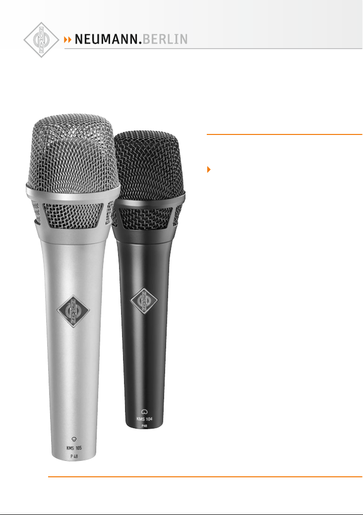
KMS 104/104 plus
KMS 105
georg neumann gmbh · leipziger str. 112 · 10117 berlin · germany
tel +49 (0)30 / 41 77 24-0 · fax -50 · headoffice@neumann.com · www.neumann.com
Page 2

Inhaltsverzeichnis
1. Kurzbeschreibung
2. Die Kondensator-Gesangsmikrofone
KMS 104/104 plus und KMS 105
3. Einige Zusatzinformationen zum Betrieb
4. Beschaltung des Mikrofonausgangs
5. Mikrofonkabel
6. Stromversorgung
7. Te chnis che Daten
8. Frequenzgänge und Polardiagramme
9. Reinigung und Pfl ege
10. Zubehör
Table of Contents
1. A Short Description
2. The KMS 104/104 plus and KMS 105 Condenser
Vocal Microphones
3. Additional Hints for Operation
4. Output Wiring
5. Microphone Cables
6. Power Supply
7. Technical Specifi cation
8. Frequency Response and Polar Patterns
9. Cleaning and Maintenance
10. Accessories
1. Kurzbeschreibung
Die Kondensatormikrofone KMS 104/104 plus
und KMS 105 sind Gesangsmikrofone der Serie
„fet 100®“ mit den Richtcharakteristiken Niere
und Superniere.
Sie zeichnen sich aus durch
• einen ein gebauten sehr w irksamen Sc hutz gegen
Popgeräusche,
• eine sehr geringe Empfi ndlichkeit für Gr iff geräusche,
• ein sehr hoch aussteuerbares, transformatorloses Schaltungskonzept,
• niedriges Eigengeräusch und saubere, off ene
und verfärbungsfreie Klangübertragung. Das
Mikrofon h at einen symmetr ischen, über tragerlosen Ausgang.
Der 3-polige XLR-Steckverbinder hat folgende
Belegung:
Pin 1: 0 V/Masse
Pin 2: Modulation (+Phase)
Pin 3: Modulation (–Phase)
Der Feldübertragungsfaktor beträgt beim KMS 104/
104 plus und KMS 105 ca. 4,5 mV/Pa
re. 1 Pa. Die Mikrofone werden mit 48 V, 3,5 mA
phantomge speist (IEC 61938). Die Einsprechrichtung ist axial.
Aufgrund des bei Gesangsmikrofonen typischen
geringen Besprechungsabstandes ist der Bassfre-
2
–47 dBV
1. A Short Description
The KMS 104/104 plus and KMS 105 are condenser
vocal microphones of the “fet 100®” Series with
cardioid and supercardioid polar pattern.
Their most important features are
• a built-in ver y eff ect ive protection against popsounds,
• a very high attenuation of handling and structure-borne noise,
• a high-loadability transformerless circuit,
• extraordinarily true sound transduction fr ee of
coloration. The microphones have a balanced,
transformerless output.
The 3-pin XLR connector has the following pin assignments:
Pin 1: 0 V/ground
Pin 2: Modulation (+phase)
Pin 3: Modulation (–phase)
The output sensitivity of the KMS 104/104 plus
and KMS 105 is 4.5 mV/Pa
micropho nes are phantom powe red at 48 V, 3.5 m A
(IEC 61938). The direction of maximum sensitivity is axial.
Due to the close-talking typical for vocal microphones the low frequency response is equalized
–47 dBV re. 1 Pa. The
Page 3

KMS 104/104 plus, KMS 105
quenzgang entsprechend dem Naheff ekt entzerrt
(s. Frequenzgangkurve).
Zusätz lich eingebaut ist je weils ein fest einge stellter Hochpass, Grenzfrequenz (–3 dB) 120 Hz, im
Freifeld gemessen.
Die Mikro fone werden zusamm en mit einer Stativklammer SG 105 geliefert.
Sie sind mit nickelmatter oder sc hwarzer Oberfl äche erhältlich.
KMS 104 ................. ni ......... Best.-Nr. 008548
KMS 104 bk ............ sw ....... Bes t.-Nr. 0085 49
KMS 104 plus ......... ni .........Best.-Nr. 008624
KMS 104 plus bk ..... sw .......Best.-Nr. 008625
KMS 105 ................. ni ......... Best.-Nr. 008454
KMS 105 bk ............ sw ....... Best.-Nr. 008455
2. Die Kondensator-Gesangsmikrofone
KMS 104/104 plus und KMS 105
Die Gesangsmikrofone KMS 104/104 plus und
KMS 105 sind für die Aufnahme von Ins trumentalund Gesa ngssolisten in s ehr kurzem Aufnahm eabstand entwickelt worden und können vom Sänger
auch in der Hand gehalten werden.
Das KMS 104/104 p lus besitzt ein e Mikrofonkapsel
mit Nierencharakteristik, die eine bestmögliche
Unterdrüc kung von rückwä rtigem Schall bie tet. Das
KMS 105 bietet die Richt charakterist ik Superniere
mit bestmöglicher Unterdrückung von Schall aus
dem hinteren Halbraum.
In beiden Mikrofonen wird durch ein sorgfältig
abgestimmtes akustisches Filter sowie durch einen transformatorlosen, sehr hoch aussteuerbaren Impedanzwandler erreicht, dass auch starke
Explosivlaute nicht zu Übersteuerungen des Mikrofons führen können. Es wird eine sehr gute
Pop-Festigkeit erzielt, wobei Zisch- und S-Laute
in ihrer natürlichen Akzentuierung übertragen
werden, wie es nur mit Kondensatormikrofonen
möglich ist.
Obwohl die akustischen Filter Störungen durch
Explosivlaute wirksam unterdrücken, bleiben die
ausgeprägten Richteigenschaften der Kapseln auch
im Bassb ereich erhalten un d geben den Gesa ngsmikrofonen eine sehr hohe Rückkopplungssicherheit
bei Bühnenbeschallung.
Die Freque nzgänge der Kaps eln und der eingebau ten Hochpassfi lter sind für Nahbesprechung opti-
corresponding to the proximity eff ect (see frequency response).
Additionally installed is a high-pass fi lter; –3 dB
poin t at 120 Hz in bot h microp hones , measu red in
free-fi eld.
The microphones come with a SG 105 stand
clamp.
They are available in nickel matt and black fi nish.
KMS 104 ................. ni ..........Cat. No. 008548
KMS 104 bk ............ blk ........ Cat. No. 008549
KMS 104 plus ......... ni ..........Cat. No. 008624
KMS 104 plus bk ..... blk ........ Cat. No. 008625
KMS 105 ................. ni ..........Cat. No. 008454
KMS 105 bk ............. blk ........Cat. No . 008455
2. KMS 104/104 plus and K MS 105
Condenser Vocal Microphones
The vocal microphones KMS 104/104 plus and
KMS 105 have been developed for the use of instrumental and vocal soloists at very close range.
They can al so be hand-held by the singer.
The KMS 104/104 plus is provided with a capsule
with cardioid characteristic, yielding the best rear
sound reje ction. The KMS 105 uses a c apsule with
supercardioid characteristic, yielding the best
front-to-back rejection ratio.
Both microphones use a carefully adjusted acoustic fi lter and a transformerless, high-loadability
impedance converter to achieve that even loud
plosive sounds do not cause overloading of the
microphone. Pop stability is excellent and sibilants and S-sounds are reproduced with all their
natural accentuation as only a condenser microphone can.
Although the acoustic fi lters eff ectively suppresse
interfe rence by plosive soun ds, the distinc tive directional characteristic of the capsules is retained
all the way down to the bass frequencies, lending
the vocal microphone a very high degree of feedback rejection when used for stage work.
The frequency responses and the in-built electrical high-pass fi lters have been optimized for very
3
Page 4

miert und kompensieren den Naheff ekt zu einem
ausgewogenen Gesamtklang. Das KMS 104 plus
zeichnet sich, im Vergleich zu KMS 104, durch
einen stärker ausgeprägten Bass-Frequenzgang
aus.
Das dickwandige Metallgehäuse der Gesangsmikrofone ist sehr robust und schützt wirksam vor
Griff geräuschen. Die akustischen Filter bestehen
aus stabilen Stahlgazen bzw. Schaumstoff , die bei
Bedarf leicht abgeschraubt und gereinigt werden
können.
close miking. They compensate the proximity effect, r esulting in an even so und reproducti on. The
KMS 104 plus features, compared to KMS 104, a
more extended bass frequency response.
The thickwalled metal case of the soloist microphones is very robust, eff ectively attenuating handling noise. The acoustic fi lters consists of stable
steel gauzes or foam which, when necessary, can
be easily unscrewed and cleaned.
3. Einige Zusatzinformationen
zum Betrieb
Der in den Mik rofonen eingebaute D C-DC-Wandler
versor gt im Gegensat z zu anderen Schaltu ngskonzepten auch den NF-Verstärker und nicht nur die
Mikrofonkapsel. Da dieser Wandler Änderungen
der Versorgungsspannung im Rahmen der erlaubten Toleranzen der Phantomspeisung ausregelt,
ver suc ht er d ies a uch, wenn d as Ne tz ab ges chal tet
wird. So b leibt die interne Spa nnung des Mikrofo ns
noch ca. 2 Sekunden erhalten, ehe sie mit einem
hörbaren „Blubb“ zusammenbricht, gefolgt von
einem kurzen Rauschen.
Vergleichbare Geräusche können auch beim Einschalten der Stromversorgung auftreten, und es
dauert einige Sekunden, bis das Mikrofon übertragungsbereit ist.
4. Beschaltung des Mikrofonausgangs
Die Zuord nung der Mikrofona nschlüsse ent spricht
IEC 60268-12:
Die Modulationsadern liegen an Pin 2 und 3, die
Abschirmung an Pin 1. Bei einem Schalldruckanstieg vor der Mikrofonmembran tritt an Pin 2 eine
positive Spannung auf.
5. Mikrofonkabel
Folgende Kabel stehen zur Verfügung:
IC 3 mt .................sw ........... Best.-Nr. 006543
Mikrofonkabel mit Doppeldrallumspinnung als
Abschirmung. Ø 5 mm, Länge 10 m. XLR 3 Steckverbinder, schwarzmatt.
3. Additional Hints for Ope ra tion
The dc-dc converter installed in the microphones
supplies , in contrast to other c ircuit concepts , also
the audio amplifi er and not only the microphone
capsule . Since this conver ter compensat es for variation of the supply voltage it tries to do this also
wh en the ac ma in is s witc hed o ff . Therefore the intern al suppl y voltag e, in the limits o f the pha ntom
power supp ly, of the microphone is ma intained for
approximately 2 seconds before it collapses with
an audible “blubb” followed by a short noise.
Noises comparable to this can be recognized also
when switching the supply on and it takes some
seconds until the microphone is ready to operate.
4. Microphone Output Wiring
The microphone is wired as per IEC 60268-12.
The modulation is connected to pins 2 and 3; the
shield is connected to pin 1. A sudden increase
in sound pressure in front of the microphone
diaphragm causes a positive voltage to appear at
pin 2.
5. Microphone Cables
The following cables are available:
IC 3 mt ................blk ............Cat. No. 006543
Micropho ne cable with doub le twist (double helix)
braiding a s shield. Ø 5 mm, le ngth 10 m. XLR 3 connectors, matte black.
4
Page 5

KMS 104/104 plus, KMS 105
AC 22 (0,3 m) ........................ Best.- Nr. 0 06598
Adapterk abel mit XLR 5 F-Buch se und 3,5 mm Stereoklinkens tecker, unsymmetr isch, für den Ans chluss
des XLR 5-Ausganges des Speisegerätes BS 48 i-2
an Geräte mit 3 ,5 mm Stereoklinkenbuchse.
AC 25 (0,3 m) ........................Bes t.-Nr. 006 600
Adapterkabel mit XLR 3 F-Buchse und 6,3 mm
Monoklinkenstecker, unsymmetrisch, für den
Anschluss des 3-poligen XLR-Ausganges eines
Speisegerätes an Geräte mit 6,3 mm Monoklinkenbuchse.
AC 27 (0,3 m) ........................Be st.-Nr. 00 6602
Y-Kabel mit ei ner XLR 5 F-Buch se und zwei 6,3 mm
Monoklinkensteckern, unsymmetrisch, für den
Anschluss des XLR 5-Ausganges des Speisegerätes BS 48 i-2 an Geräte mit 6,3 mm Monoklinkenbuchsen.
Weitere Artikel sind im Katalog „Zubehör“ beschrieben.
6. Stromversorgung
6.1 Phantomspeisung
Die Mikro fone der Serie „fe t 100®“ werden mit 4 8 V
phantomgespeist (P48, IEC 61938).
Bei der Phantomspeisung fl ießt der Speisestrom
vom positiven Pol der Spannungsquelle über die
elek tri sche Mitte der beiden Modulationsadern
zum M ikro fon . Er w ird h ierz u übe r zwe i gle ichg roß e
Wider stände beiden Tonadern gleichsinnig zugeführt. Die Rückleitung des Gleichstroms erfolgt
über den Kabelschirm. Zwischen beiden Modulationsadern besteht also keine Potentialdiff erenz.
Daher ist mi t der Phantomspeisun g eine kompatible Anschlusstechnik möglich:
Auf die Anschlussdosen können wahlweise auch
dynamische Mikrofone oder Bändchenmikrofone
sowie die Modulationskabel röhrenbestückter
Kondensatormikrofone geschaltet werden, ohne
dass die Speisegleichspannung abgeschaltet werden muss.
Der Ausg ang eines Neumann- Phantomspeisege rätes darf auch auf bereits ander weitig phantomgespeiste Mikrofoneingänge gesteckt werden.
AC 22 (0.3 m) .........................Cat. No. 006598
Adapter cable with XLR 5 M connector and unbalanc ed 3 .5 mm st ereo jack . It is used to co nnec t the
5-pin XLR output of the BS 48 i-2 power supply to
units with a 3.5 mm stereo input.
AC 25 (0.3 m) ........................ Cat. No. 006600
Adapter cable with XLR 3 M connector and unbalanced 6.3 mm mono jack. It is used to connect
3-pin XLR outputs of power supplies to units with
a 6.3 mm monojack input.
AC 27 (0.3 m) ........................ Cat. No. 006602
Y-cable with XLR 5 M connector and two unbalanced 6.3 mm mono jacks. It is used to connect
XLR 5 outputs of t he BS 48 i-2 power supply to unit s
with 6.3 mm monojack inputs.
Further articles are described in the catalog “Accessories”.
6. Power Supply
6.1 Phantom Powering
The “fet 100®” Series microphones are phantompowered at 48 V (P48, IEC 61938).
With phantom powering the dc from the positive
supply terminal is divided via two identical resistors, one h alf of the dc fl owing through e ach audio
(modulatio n) conductor to the micro phone, and returning to the voltage source via the cable shield.
Phantom powering provides a fully compatible
connecting system, since no potential diff erences
exist bet ween the two audio conductors.
Studio outlets so powered will therefore also
accept dynamic microphones and ribbon microphones as well as the modulation conductors of
tube-equipped condenser microphones without
the need to switch off the dc supply voltage.
No harm is done even if a Neumann phantom
power supply is connected to the inputs of microphones w hich are phantom powere d from another
source.
5
Page 6

6.2 Betrieb mit Netzgeräten
Für die Stromve rsorgung sind al le P48-Netz geräte
geeignet, die mindestens 3,5 mA je Kanal abgeben.
Das Neuman n P48-Netzg erät hat die Bezeich nung
N 248. Es ist zur Stromversorgung zweier MonoKondensatormikrofone oder eines Stereomikrofons
mit 48 V ± 1 V, maximal 2 x 6 mA , geeignet (siehe
auch Neumann-Druckschrift 68832: „48 V-Phantomspeisegeräte“).
Die Zuordnung der Mikrofonanschlüsse und die
Polarität der Modulationsadern ist am Ausgang des
Speisegerätes die gleiche wie am Mikrofon.
Alle Anschlüsse mit XLR 3-Flanschdosen. Die Modulationsausgänge sind gleichspannungsfrei.
Folgende Ausführungsformen sind erhältlich:
N 248 ................... sw ........... Be st.-Nr. 008537
6.2 ac Supply Operation
All P48 power supplies in accordance with IEC 61938
which prov ide at least 3. 5 mA p er cha nnel, are suitable for powering the microphones.
The Neumann P48 power supply unit bears the
designation N 248. It is designed to power two
mono condenser microphones or one stereo microphone at 48 V ± 1 V, max. 2 x 6 mA (see also
Neumann bulletin no. 68832: ”Phantom 48 VDC
Power Supplies“).
The assignment of the microphone terminals and
the modul ation polar ity at the power sup ply output
are identical to those at the microphone.
All connectors are of XLR 3 type. The audio signal
outputs are DC-free.
These versions are available:
N 248 ...................blk ............Cat. No. 008537
6.3 Batteriespeisung
Steht keine Net zspannung zur Verf ügung, kann die
Speisung mit einem der Geräte
BS 48 i .................................Best.-Nr. 006494
(für ein Mikrofon)
BS 48 i-2 ..............................Best.-Nr. 006496
(für zwei Mikrofone)
erfolgen. Beide Geräte liefern 48 V ± 1 V, maximal
je 5 mA, un d werden jeweils vo n einer 9 Volt-Blo ckbatter ie Typ IEC 6 F 2 2 g espeist .
Das Gerät B S 4 8 i -2 ist mit 5-poligen , das BS 48 i m it
3-poligen XLR-Steckverbindern ausgerüstet.
(Siehe auch Neumann-Druckschrift 68832 ... „48 VPhantomspeisegeräte“).
Die Zuordnung der Mikrofonanschlüsse und die
Polarität der Modulationsadern ist am Ausgang der
Speisegeräte die gleiche wie am Mikrofon.
6.4 Betrieb an unsymmetrischen oder
mittengeerdeten Eingängen
Die 48 V-Phantom-Speisegeräte BS 48 i, BS 48 i-2
und N 248 haben gl eichspannungs freie Ausgänge,
so dass für den Anschluss an unsymmetrische
Eingänge kein Übertrager erforderlich ist.
Beim KMS 104/105 i st Pin 2 normgemäß die „heiß e
Phase“. Für unsymmetrische Eingänge muss Pin 3
am Ausgang des Speisegerätes an Masse gelegt
werden (siehe Abbildung 1).
6
6.3 Battery Powering
If a mains powe r source is not availa ble, power can
be supplied by one of the battery units
BS 48 i ...................................Cat. No. 006494
(for one microphone)
BS 48 i-2 ................................Cat. No. 006496
(for two microphones)
Both units deliver 48 V ± 1 V, at 5 mA maximum,
and are powered by a 9-volt monobloc battery
Type IEC 6 F 22.
The BS 48 i-2 is equipped with 5-pin XLR connectors, the BS 48 i with 3-pin XLR connectors.
(See Neumann bulletin 68832... “Phantom 48 VDC
Power Supplies”.)
The assignment of the microphone terminals and
the modul ation polar ity at the power sup ply output
are identical to those at the microphone.
6.4 Operation with Unbalanced or
Center Tap Grounded lnputs
The BS 48 i, BS 48 i-2 and N 248 phantom 48 Vdc
power supplies are dc-free so that no transformer
is required for connec tion to unbalanced inputs.
In the case of the KMS 104/105 condenser microphone pin 2 is the “hot phase“, in accordance with
the standard, and pin 3 of the output of the power
supply must be connec ted to earth (see Fig. 1).
Page 7

KMS 104/104 plus, KMS 105
Bei vielen anderen als
den o.g. Phantomspeisegeräten liegen nicht nur
die Modulationsleitungen
zum Mikrofon auf dem
Potential d er Speisespan nung von +48 V, sondern
auch die vom Sp eisegerät
abgehenden Modulationsleitungen. Für die in der
Studiotechnik allgemein
üblichen symmetrischen
und erdfreien Verstärker
und Mischpulteingänge
ist dies ohne Bedeutung.
Dagegen w ird die Speisespannung beim Anschluss
an einseitig oder mittengeerdete Verstärkereingänge kurzgeschlossen,
und es ist kein Betrieb
möglich. Dann bestehen
folgende Lösungsmöglichkeiten:
a) In mittengeerdeten
Geräten mit Eingangsübertrager (z.B. einige
NAGRA-Geräte) kann die
betreff ende Erdverbindung
fast immer ohne Nachteile
für die Funktion des Gerätes aufgetrennt werden.
b) In jede abgehende Modulationsleitung kann
zur Abblo ckung der 48 V-Gleichsp annung eine RCKombinatio n eingefügt werden (si ehe Abbildung 2
und Neumann-Information Nr. 84 221).
Abbildung / Figure 1
Abbildung / Figure 2
In the c ase of many o ther
phantom powering units
(except those mentioned
above), not only the
modulation leads to the
microphone, but also
the outgoing modulation
leads from the powering
unit, are at the potential of the feed voltage
(+48 V). This is of no
signifi cance for the balanced, fl oating amplifi er
and mixing c onsole inputs
in general studio use. On
the other hand, the feed
voltage will be short-circuited when connected
to single-ended or center
tap grounded amplifi er
inputs, and no operation
will be possible. This can
be circumvented as follows:
a) In center tap grounded equipment with input
transformer (e.g. some
NAGRA units), the earth
lead can almost always
be disconnected without
aff ecting the function of
the equipment.
b) In every outgoing modulation lead, an RC
net-work can be incorporated to block the 48 Vdc
voltage (See Figure 2 and Neumann-Information
no. 84 222).
6.5 Betrieb an HF-Sendern
Die Gesangsmikrofone können an Ansteck- oder
Taschensendern betrieben werden, die folgende
Vorraussetzungen erfüllen:
• Phantomspeisung 48 V, mind. 3,5 mA
• Pin 2 signalführend („heiß“)
• ausreichender Dynamikbereich des Senders
6.5 Operation with Wireless Transmitters
Both microphones can be operated with plug-on
or pocket transmitters fulfi lling these specifi cations:
• P48 Phantom power, 3.5 mA min.
• Signal on pin 2 (“hot”)
• suffi cient dynamic range of the transmitter
7
Page 8

7. Technische Daten
KMS 104/KM S 104 plus/KMS 105
7. Technical Specifi cations
KMS 104/KM S 104 plus/KMS 105
Akustische Arbeitsweise .......... Druckgradienten-
empfänger
Richtcharakteristik ........Niere/Niere/Superniere
Übertragungsbereich .................. 20 Hz...20 kHz
Feldübertragungs-
faktor1) ....................4,5 mV/Pa ± 1 dB –47 dBV
Nennimpedanz .......................................50 Ohm
Nennlas ti mpe dan z ............................. 1000 Ohm
Geräuschpegelabstand2),
CCIR3) .......................................................66 dB
Geräuschpegelabstand2),
A-bewertet3) .............................................76 dB
Ersatzgeräuschpegel,
CCIR3) .......................................................28 dB
Ersatzgeräuschpegel,
A-bewertet3) ......................................... 18 dB-A
Grenzschalldruckpegel für
0,5 % Klirrfaktor4) ................................... 150 dB
Max. Ausgangsspannung ..........................12 dBu
Speisespannung5) ...............................48 V ± 4 V
Stromaufnahme5) ....................................3,5 mA
Erforderlicher Steckverbinder ..................XLR3F
Gewich t ................................................ ca . 300 g
Durchme sser ........................................... 48 mm
Länge .................................................... 18 0 mm
Acoustical op. principle ...........Pressure gradient
Direct ional pattern ................ cardioid/cardioid/
transducer
supercardioid
Frequency range .........................20 Hz...20 kHz
Sensitivity 1) ............4.5 mV/Pa ± 1 dB –47 dBV
Rated impedance ...................................50 ohms
Rated load impedance ...................... 1000 ohms
Signal-to-noise ratio2),
CCIR3) ....................................................... 66 dB
Signal-to-noise ratio2),
A-weighted3) .............................................76 dB
Equivalent noise level,
CCIR3) .......................................................28 dB
Equivalent noise level,
A-weighted3) ......................................... 18 dB-A
Maximum SPL
for less than 0.5 % THD4) ......................... 150 dB
Max. output voltage .................................12 dBu
Supply voltage5) ..................................48 V ± 4 V
Current consumption5) ........................... 3.5 m A
Matching connector ..................................XLR3F
Weight........................................... ap prox. 300 g
Diameter ................................................. 48 mm
Length ................................................... 180 mm
94 dB SPL entspr. 1 Pa = 10 μbar
0 dB entspr. 20 μPa
1)
bei 1 k Hz an 1 kOhm Nennlasti mpedanz.
2)
bezogen auf 94 dB SPL
3)
nach IEC 60268-1;
CCIR-B ewertung nac h CCIR 468-3, Qu asi-Spitzen wert;
A-Bewe rtung nach IEC 61672-1, Eff ektivwert
4)
Klirrfaktor d es Mikrofonve rstärkers b ei einer Eingang sspannung,
die der von de r Kapsel beim en tsprechend en Schalldruc k abgegebenen Spannu ng entspric ht.
5)
Phantomspeisun g (P48, IEC 61938).
8
94 dB SPL equiv. 1 Pa = 10 μbar
0 dB equiv. 20 μPa
1)
at 1 kH z into 1 kohms rated load imp edance.
2)
re 94 dB SPL
3)
accordin g to IEC 60268-1;
CCIR-we ighting accco rding to CCIR 46 8-3, quasi peak ;
A-weigh ting accordin g to IEC 61672-1, RMS
4)
THD of micr ophone amplifi er at an input volt age equivalent
to the cap sule output at th e specifi ed SPL.
5)
Phantom powerin g (P48, IEC 61938).
Page 9

KMS 104/104 plus, KMS 105
8. Frequenzgänge und Polardiagramme
Frequency Responses and Polar Patterns
KMS 104
gemess en im freien Scha llfeld nach IEC 602 68-4 / measur ed in free-fi eld condition s (IEC 60268-4)
KMS 104 plus
KMS 104 / 104 plus
9
Page 10

KMS 105
gemess en im freien Scha llfeld nach IEC 602 68-4 / measur ed in free-fi eld condition s (IEC 60268-4)
KMS 105
10
Page 11

KMS 104/104 plus, KMS 105
9. Reinigung und Pfl ege
Die Gesangsmikrofone KMS 104/104 plus und
KMS 105 sind für den Bühneneinsatz konstruiert
und sehr resistent gegen Umwelteinfl üsse. Dennoch sollten einige Verhaltensweisen beachtet
werden, um die unbeschränkte Lebensdauer der
Mikrofone zu garantieren.
9.1 Reinigung
Der Korb der Mikrofone kann nach längerem
Gebrauch auf einfache Weise gereinigt werden.
Dazu den Mikrofonkorb abschrauben und den
darin enthaltenen Gazezylinder beim KMS 105
bzw. Schaumstoff beim KMS 104/104 plus herausnehmen. Mikrofonkorb und Schaumstoff bzw.
Gazezylinder können dann in Wasser oder leichten
Lösungsmitteln vorsichtig gereinigt werden. Nach
dem Trocknen wieder auf das Mikrofongehäuse
schrauben. Darauf achten, dass die Gaze des Gazezylinders nicht beschädigt wird, da diese einen
wichtigen Bestandteil des Popschutzes darstellt.
Vorsicht : Ohne Mikrofonkor b liegt die Mikrof onkapsel relat iv ungeschüt zt frei. Darauf a chten, dass die
Kapsel nicht beschädigt wird. Das Mikrofongehäuse inklusive Verstärker enthalten keine weiteren zu
reinigenden Teile und sind durch spezielle Lackierungen geschützt.
9.2 Weitere Pfl ege
Staubschutz verwenden: Mikrofone, die nicht im
Einsatz sind, sollte man generell nicht auf dem
Stativ einstauben lassen. Mit einem Staubschutzbeutel (nicht fusselnd) wird die s verhindert. Wird
ein Mikrofo n längere Zeit nicht v erwendet, s ollte es
in einem Schrank bei normalem Umgebungsklima
aufbewahrt werden.
Keine überalterten Windschutze verwenden: Auch
Schaumstoff altert. Das M aterial kann brüchig un d
krümelig werden. Anstatt das Mikrofon zu schützen, kann er dann zur Verunreinigung der Mikrofonkapsel führen. Überalterte Windschutze also
bitte entsorgen.
9. Cleaning and Maintenance
The KMS 104/104 plus und KMS 105 vocal microphones are designed for stage use and very resistent against adverse environments. Still, some
remarks are helpful to guarantee the unlimited
operating life of the microphone.
9.1 Cleaning
After prolonged use, the head grille of the microphones can be cleaned very simply. Just unscrew
the head grille and take out the included gauze
cylinder or foam. Head grille and gauze cylinder/
foam can th en be cleaned in wate r or mild solvents .
After drying, just reassemble the microphone.
Please take care not to damage the gauze on the
gauze cylin der, as it represent s an important fa ctor
for pop protection.
Attent ion: Without the h ead grille, the mi crophone
capsule is relatively unprotected. Please make sure
not to damage the capsule. The microphone housing includi ng the amplifi er ho ld no further ser viceable parts, and are furthermo re protected by some
special lacquers.
9.2 Further Maintenance
Use a dust cover: Microphones not in use should
generally not be left on the stand unprotected.
With a non-fl uff y dust cover the microphone can
be protected from dust settling on the capsule.
When not in u se for a longer spell , the microphone
should be stored in a closet at standard climatic
conditions.
Do not use overaged wind shields: Even the foam
material of wind shields ages. With very old wind
shields, the material decays and becomes brittle.
The particles can then settle on the diaphragm.
Please dispose of overaged wind shields.
11
Page 12

10. Zubehör
Weitere Artikel sind im Katalog „Zubehör“ beschrieben.
Stativgelenke
SG 105 ................sw ............. Best.-Nr. 08460
(gehört zum Lieferumfang)
Schnellspannklammer aus Kunststoff für Gesang smikrofone KMS. Die Klammer ist schwenkbar und
hat einen Gewindeanschluss 5/8"-27-Gang, mit
Adapter für 1 /2"- und 3/8"-Stative.
10. Accessories
Further articles are described in the catalog “Accessories”.
Stand Mounts
SG 105 ................blk ..............Cat. No. 08460
(included in the supply schedule)
Stand clamp for KMS vocal microphones. The
clamp can be swivelled and has a 5/8"-27 thread,
plus a thread adapter to connect to 1/ 2"- and 3/8"
stands.
Tisch- und Fußbodenständer
MF 3 ..................... s w ..............Best.-Nr. 07321
Der Mikrofonfuß MF 3 ist ein Tischständer mit Eisenfuß, 1,6 kg schwer, Durchmesser 110 mm. Der
Ständer is t schwarzmatt l ackiert und ste ht gleitfest
auf einer Moosgummischeibe. Ein umwendbarer
Gewindezapfen und ein mitgeliefertes Reduzierstück ermöglichen die Verwendung für 1/2"- und
3/8"-Gewindeanschlüsse.
MF 4 ..................... s w ..............Best.-Nr. 07337
Der Mikrofonfuß MF 4 ist ein Fußbodenständer
aus Grauguss, ca. 2,6 kg schwer, Ø 160 mm. Der
Ständer is t schwarzmatt l ackiert und ste ht gleitfest
auf einem Gummiring. Ein umwendbarer Gewindezapfen und ein mitgeliefertes Reduzierstück
ermöglichen die Verwendung für 1/2"- und 3/8"Gewindeanschlüsse.
MF 5 ..................... gr .............. B est.-Nr. 08 489
Der Mikrofonfuß MF 5 hat eine graue Soft-Touch
Pulverbeschichtung und steht gleitfest und trittschalldäm mend auf einem Gummir ing. Der Stativanschluss hat ein 3/8"-Gewinde. Gewicht 2,7 kg,
Ø 250 mm.
Stativverlängerungen
STV 4 ....................s w ............. Be st.-Nr. 06190
STV 20 ..................s w ............. Bes t.-Nr. 06187
STV 40 ................. sw ............. B est.-Nr. 0618 8
STV 60 ................. sw ............. B est.-N r. 0 6189
Die Stativverlängerungen STV ... werden zwischen
Mikrofon ständer (z.B. MF 4, MF 5) und Stativg elenk
(z.B. SG 21 /17 mt) gesch raubt.
Die STV ... haben eine Länge von 40, 200, 400
oder 600 mm. Ø 19 mm.
Table and Floor Stands
MF 3 .....................blk ..............Cat. No. 07321
The MF 3 is a table stand with iron base, 1.6 kg in
weight, 110 mm in diameter. It has a black matte
fi nish. The bottom is fi tted with a non-slip rubber
disk. The stand comes with a reversible stud and
an adapter for 1/2" and 3/8" threads.
MF 4 .....................blk ..............Cat. No. 07337
Floor stand with grey cast iron base. The fl oor
stand has a matt black fi nish and rests on a nonskid rubb er disk attached to the bottom. A r eversible stud and a reducer for 1/2" and 3/8" threads
are also supplied. Weight 2.6 kg, Ø 160 mm.
MF 5 .....................gr ................Cat. No. 08489
Floor stand with grey soft-touch powder coating.
It has a non-skid sound-absorbing rubber disk attached to the bottom. The stand connection has a
3/8" thread. Weight 2.7 kg, Ø 250 mm.
Stand Extensions
STV 4 .................... blk .............. Cat. No. 06190
STV 20 .................. blk ..............Cat. No. 06187
STV 40 .................blk ..............Cat. No. 06188
STV 60 .................blk ..............Cat. No. 06189
The STV... stand extensions are screwed between
microphone stands (for example MF 4, MF 5) and
swivel mounts (for example SG 21/17 mt).
Length 40, 200, 400 or 600 mm. Ø 19 mm.
12
Page 13

KMS 104/104 plus, KMS 105
Schaumstoff windschutze
WSS 100 .............schwarz .....Best.-Nr. 07352
WSS 100 .............rot .............Best.-Nr. 07353
WSS 100 .............grün .......... Best.-Nr. 07354
WSS 100 .............gelb ...........Best.-Nr. 07355
WSS 100 .............blau .......... Best.-Nr. 07356
WSS 100 .............weiß ..........Best.-Nr. 07357
Zusätzlich zum Drahtgazekorb, der das Mikrofon
vor Wind- u nd Popgeräuschen schütz t, ist ein aufsteckbarer Windschutz aus offenporigem Polyurethanschaum lieferbar, und zwar in den Farben
schwarz, altweiß, rot, grün, blau und gelb. Ø ca.
90 mm.
Diese Windschutze erzeugen keine störenden Resonanzen un d beeinfl ussen den Frequ enzgang des
Übertragungsmaßes nur geringfügig (bei 15 kHz
ca. –3 dB).
Dämpfung des Windgeräusches 27 dB, gemessen
ohne elektrisches Filter in verwirbelter Luftströmung der Geschwindigkeit 20 km/h, erzeugt von
einer geräuschlos arbeitenden Windmaschine.
Foam Windscreens
WSS 100 .............black........... Cat. No. 07352
WSS 100 .............red .............. Cat. No. 07353
WSS 100 .............green ..........Cat. No. 07354
WSS 100 .............yellow ......... Cat. No. 07355
WSS 100 .............blue ............Cat. No. 07356
WSS 100 .............white ..........Cat. No. 07357
In addition to the wire mesh cage protecting the
micropho ne against wind a nd pop noises an op encell polyurethane foam windscreen is available in
the colo rs bl ack , ivo ry, r ed, g reen , blu e and yell ow.
Ø 90 mm.
These windscreens have no disturbing resonances
and only slightly aff ect the frequency response (i.e.
approx. – 3 dB at 15 kHz).
Wind noise attenuation 27 dB measured (without
electr ical fi lter) in pulsating a ir currents produ ced
by a noiseless wind machine at 20 km/h.
13
Page 14

IC 3 mt
AC 22
AC 25
AC 27 N 248
BS 48 i-2
MF 3
SG 105
MF 4
BS 48 i
STV ...
14
Page 15

KMS 104/104 plus, KMS 105
MF 5 WSS 100
15
Page 16

Haftungsausschluss
Die Geor g Neumann GmbH über nimmt keinerlei Ha ung für Fol gen eines
unsach gemäßen Ge brauchs de s Produkt s, d.h. die Fo lgen eines G ebrauchs ,
der von den i n der Bedien ungsanlei tung genann ten technisc hen Vorauss etzungen abweicht (z.B. Bedienungsfehler, mechanische Beschädigungen,
falsch e Spannung, A bweichung von emp fohlenen Korr espondenz geräten).
Jegliche Ha ung de r Georg Neumann Gmb H für Schäden und Folgeschä den, die dem Benutzer aufgrund eines s olchen abweichen den Gebrauchs
entstehen sollten, wird ausgeschlossen. Ausgenommen von diesem Haftungsausschluss sind Ansprüche aufgrund zwingender gesetzlicher Haftung, w ie z.B. nach P roduktha ungsgesetz.
Limitation of Liab ility
Georg N eumann GmbH shal l not be liable for co nsequence s of an inappropriate u se of the produ ct not being in co mpliance wi th the technic al allowanc e in th e us er man ual s uch a s han dlin g err ors , mec hani cal s poi ling , fal se
voltage and using other than the recommended correspondence dev ices.
Any liabili ty of Georg Ne umann GmbH for any d amages includ ing indirect ,
consequential, special, incidental and punitive damages based on the
user’s non-compliance with the user manual or unreasonable utilization
of the product is hereby excluded as to the extent permitted by law. This
limitation of liability on damages is not applicable for the liability und er
Europea n produc t liability codes or for users in a state or country wh ere
such damag es can not be limit ed.
Konformitätserk lärung
Die Geor g Neumann Gm bH erklär t, dass die ses Gerä t die anwendb aren
CE-Nor men und -Vorsch riften er füllt.
Neumann i st in zahlr eichen Lä ndern ein e eingetr agene Mar ke der
®
Georg N eumann GmbH.
Decl aration of Conf ormity
Georg Neumann GmbH hereby declares that this device conforms to
the applicable CE s tandards and regulations.
Neuma nn is a registered t rademark of the G eorg N eumann GmbH in
®
certain countries.
Irrtüm er und technische Ä nderungen vorbehalten • Errors excepted, subject to changes
Printed in Germany • P ubl. 10/14 533181/A02
 Loading...