

Page 1
KMR D
B
O M
Registrieren Sie bitte Ihr
System auf der Website
www.my-Solution-D.com,
um über Updates informiert
zu werden!
Please register your system
on the website
www.my-Solution-D.com,
to be informed whenever updates
are available!
· . · ·
() / - · - · @. · ..
Page 2

1. Einleitung
In dieser Anleitung nden Sie alle wichtigen Informationen für den Betrieb und die P ege der
von Ihnen erworbenen Produkte. Lesen Sie diese
Anleitung sorg fältig und vollständig, bevor Sie die
Geräte benutzen. Bewahren Sie sie so auf, dass
sie für alle momentanen und späteren Nutzer jederzeit zugänglich ist.
Weitergehende Informationen, insbesondere
auch zu den verfügbaren Zubehörteilen und den
Neumann-Servicepartnern, nden Sie jederzeit
auf unserer Website www.neumann.com. Die
Servicepartner können Sie auch telefonisch unter
+49 (0) 30 / 41 77 24 - 0 er fragen.
Auf unserer Website www.neumann.com nden
Sie in der Rubrik Downloads ergänzend folgende
PDF-Dateien:
• Hinweise zur P ege des Mikrofons
• Bedienungsanleitung DMI-2, DMI-2 portable
und DMI-8 (Digitales Mikrofon-Interface)
• Bedienungsanleitung RCS (Remote Control
So ware)
• Bedienungsanleitung Connection Kit
• Kurzbeschreibung des Standards AES42
In der Rubrik Downloads steht auch die aktuelle
Version der Mikrofon- und DMI-So ware sowie
der RCS zur Verfügung.
Weitergehende Informationen zur Schnittstelle
digitaler Mikrofone nden Sie bei www.aes.org/
standards unter „AES standards for acoustics, Digital interface for microphones“.
Zum weltweiten Erfahrungsaustausch unter Neumann-Anwendern bieten wir auf unserer Website
das Neumann Online-Forum an, das sich durch
die integrierte Archivfunktion zu einem umfangreichen Know-How-Pool entwickelt hat.
2. Sicherheitshinweise
Der bestimmungsgemäße Gebrauch dieses Mikrofons ist die Wandlung akustischer in digitale
elektrische Signale.
Schließen Sie das Mikrofon nur an Mikrofon-
eingänge und Speisegeräte an, die eine Phantomspeisung nach AES42 liefern.
Das Mikrofon wird jedoch nicht beschädigt, falls
es versehentlich kurzzeitig an einen analogen Mikrofoneingang mit 48 V-Phantomspeisung ange-
schlossen wird. Das KMR 8 1 D ist gegen Überspannung geschützt und verträgt kurzzeitig bis +55 V.
Reparatur- und Servicearbeiten dürfen nur von
erfahrenem und autorisiertem Fachpersonal
durchgeführt werden. Wenn Sie die Geräte eigenmächtig ö nen oder umbauen, erlischt die Gewährleistung.
Verwenden Sie das Mikrofon nur in dem in den
Technischen Daten angegebenen Leistungsbereich.
Lassen Sie das Mikrofon auf Umgebungstemperatur akklimatisieren, bevor Sie es einschalten.
Nehmen Sie das Mikrofon nicht in Betrieb, wenn
es beschädigt ist.
Verlegen Sie Kabel s tets so, dass niemand darüber
stolpern kann.
Halten Sie Flüssigkeiten und elektrisch leitfähige
Gegenstände, die nicht betriebsbedingt notwendig sind, von den Geräten und deren Anschlüssen
fern.
Verwenden Sie zum Reinigen keine Lösungsmittel
oder aggressiven Reinigungsmittel.
Entsorgen Sie die Geräte nach den Bestimmungen
Ihres Landes.
3. Kurzbeschreibung
Das digitale Mikrofon KMR 81 D ist ein Kondensatormikrofon der Solution-D-Familie mit digitalem
Ausgang gemäß dem internationalen Standard
AES42. Dieser basiert auf dem in Studiogeräten
üblichen Standard AES3 (AES/EBU) für digitale
Audiosignale, erweitert um die Phantomspeisung
für das Mikrofon, um Fernsteuer- und Synchronisationsdaten sowie um User-Bits zur Übertragung
von Mikrofoninformationen.
Durch die Verwendung eines Interferenzrohres
vor der Kapsel wird die Richt wirkung im Vergleich
zu einfachen Druckgradientenempfängern im
Bereich mittlerer und höherer Frequenzen signi kant gesteigert.
Das Mikrofon zeichnet sich aus durch besonders
saubere und verfärbungsfreie Klangübertragung bei sehr niedrigem Eigengeräuschpegel
und gleichzeitig höchster Aussteuerbarkeit. Es
verwendet zur Digitalisierung ein von Neumann
entwickeltes und patentiertes A/D-Wandlungsverfahren. Dadurch ist sichergestellt, dass der
gesamte Dynamikumfang des Kapselsignals in
2
D
Page 3
die digitale Ebene überführt wird. Mit der integrierten digitalen Signalverarbeitung bietet das
Mikrofon außerdem Funktionen, die bisher nur
im Mischpult oder zusätzlichen Geräten realisiert
werden konnten. Diese Funktionen werden im Kapitel Technische Daten beschrieben.
Steht zum Anschluss des Mikrofons kein AES42Eingang (z. B. am Mischpult) zur Verfügung, bietet
Neumann verschiedene Anschlussmöglichkeiten
an: Connection Kits zur reinen Stromversorgung
sowie das zweikanalige Digitale Mikrofon-Interface DMI-2 oder DMI-2 portable und das achtkanalige DMI-8 mit der dazugehörigen Steuerso ware
RCS zur Fernsteuerung aller Mikrofoneigenschaften (siehe auch Kapitel Technische Daten).
Die Leistungsaufnahme des Mikrofons führ t zu einer Eigenerwärmung, die mit kleineren Kabellängen und höheren Abtastraten zunimmt.
4. Inbetriebnahme
Mikrofon einrichten
Befestigen Sie das Mikrofon mit der dafür vorgesehenen Halterung auf einem ausreichend stabilen und standfesten Stativ etc. Verwenden Sie
ggf. eine elastische Au ängung aus unserem Zubehör-Angebot, um Trittschall durch mechanische
Entkopplung zu unterdrücken.
Extrem niederfrequente Signale können durch
Störungen wie Körperschall oder Pop- und Windgeräusche hervorgerufen werden. Um solche
Störsignale zu unterdrücken, empfehlen wir, eine
elastische Au ängung, einen Windschutz oder
einen Popschirm aus unserem Zubehörprogramm
zu verwenden.
Mikrofon anschließen
Vorsicht: Eine falsche Versorgungsspannung
kann das Mikrofon beschädigen!
Schließen Sie das Mikrofon nur an Mikrofoneingänge und Speisegeräte an, die eine Phantomspeisung nach AES42 liefern. Siehe auch Kapitel
„Sicherheitshinweise“.
Vorsicht: Sehr hohe Signalpegel können Ihr
Gehör und Ihre Lautsprecher schädigen!
Reduzieren Sie an den angeschlossenen Wiedergabegeräten die Lautstärke, bevor Sie das Mikrofon anschließen, auch wegen der Gefahr der akustischen Rückkopplung.
Verbinden Sie das Mikrofon über ein XLR-Kabel
mit dem AES42-Mikrofoneingang Ihres Digitalen
Mikrofon-Interface DMI, des Neumann Connection Kits oder eines anderweitigen Audiogerätes
nach AES42.
Für die Verbindung des DMI und des Connection
Kits mit ihrem Audiogerät lesen Sie bitte die entsprechende Bedienungsanleitung.
Eine blaue LED im Mikrofon zeigt bei korrekter
Speisung die Betriebsbereitscha an. Sie leuchtet
beim Einschalten zunächst schwach und nach kurzer Zeit mit der voreingestellten Helligkeit. Diese
kann bei Verwendung des Digitalen MikrofonInterfaces DMI mit der Remote Control So ware
in vier Stufen variiert und ausgeschaltet werden.
Achten Sie beim Anschließen von Kabeln auf die
korrekte Verriegelung der Steckverbinder.
Lange Kabel und mehrfache Steckverbindungen
führen zu einer Verschlechterung des Jitter-Verhaltens insbesondere bei hohen Abtastraten. Verwenden Sie daher möglichst durchgehende Kabelverbindungen zwischen Mikrofon und Folgegerät
und bei größeren Distanzen ausschließlich AES/
EBU-Kabel (Wellenwiderstand 110 Ohm).
Achten Sie darauf, dass das Mikrofon und alle Geräte der digitalen Signalkette synchronisiert sind.
Wird das Digitale Mikrofon-Interface von Neumann verwendet, sollten die angeschlossenen Mikrofone immer im Synchronmode betrieben werden, unabhängig davon, ob in der nachfolgenden
Signalkette Sample Rate Converter im Einsatz
sind. Auf diese Weise wird im DMI eine sehr effektive Jitterunterdrückung wirksam. Auch ist die
Ausgabe zweier Mikrofonsignale in einem AES3Stereosignal nur möglich, wenn die Mikrofone untereinander synchron arbeiten.
Tontest
Sprechen Sie das Mikrofon einfach nur an. Anpusten oder „Anploppen“ führt zu gefährlichen
Schalldruckpegeln.
Parameter, die über die AES42-Schnittstelle
ferngesteuert werden können
Low Cut: Der Low Cut bietet gemäß AES42-Standard die vier Einstellungen: o , 40 Hz, 80 Hz und
160 Hz.
Vordämpfung: Die Vordämpfung wird durch Reduktion der Kapselspannung realisiert. Bei Aktivierung wird der Dynamikbereich um den ent-
3
D
Page 4
sprechenden Wert zu höheren Schalldruckpegeln
verschoben.
Gain: Die Verstärkung erfolgt ausschließlich auf
der digitalen Ebene und führt damit nicht zu der
aus der analogen Welt bekannten Rauschaddition
und zu möglichen Klangbeein ussungen.
Peak-Limiter: Der sehr schnelle Peak-Limiter hat
eine einstellbare Ansprechschwelle und verhindert Übersteuerungen bzw. Clippen des Audiosignals im Signalweg.
Kompressor/Limiter: Weiterhin ist ein vollständig
parametrisierbarer Kompressor/Limiter implementiert. Dieser kann breitbandig oder als Hochtonkompressor/Limiter (De-Esser) in einem von
drei wählbaren Frequenzbereichen arbeiten. Alle
wichtigen Parameter sind einstellbar.
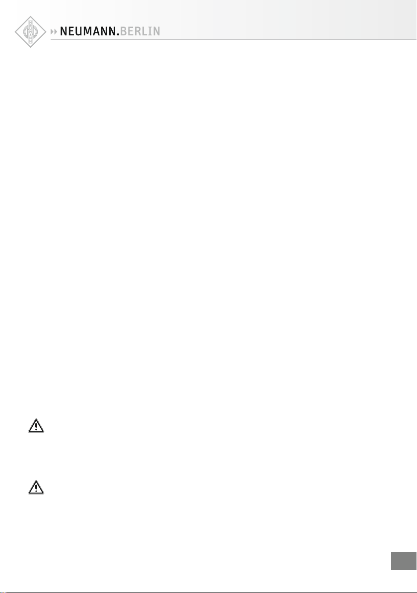
Abb. 1
a
= KMR 81 D nx
b
= KMR 81 D nx + WS 81
Außerdem lassen sich die Abtastrate, der Synchronisationsmodus, Testsignale, Mute, die Polarität des Ausgangssignals und die LED fernsteuern.
Die So ware im Mikrofon kann über das Neumann DMI ak tualisiert werden, so dass zukün ige
Erweiterungen der So ware auch bestehenden
Kunden zur Verfügung stehen. Zu Details des Updatevorganges lesen Sie bitte die RCS-Anleitung.
Empfehlung für den Gebrauch der
Windschutzeinrichtungen
Zur Vermeidung von Störgeräuschen, die bei Nahbesprechung, Windein uss oder beispielsweise
bei schnellem Schwenken des Mikrofons au reten können, sind verschiedene Windschutzeinrichtungen lieferbar (siehe auch Kapitel Zubehör).
a
b
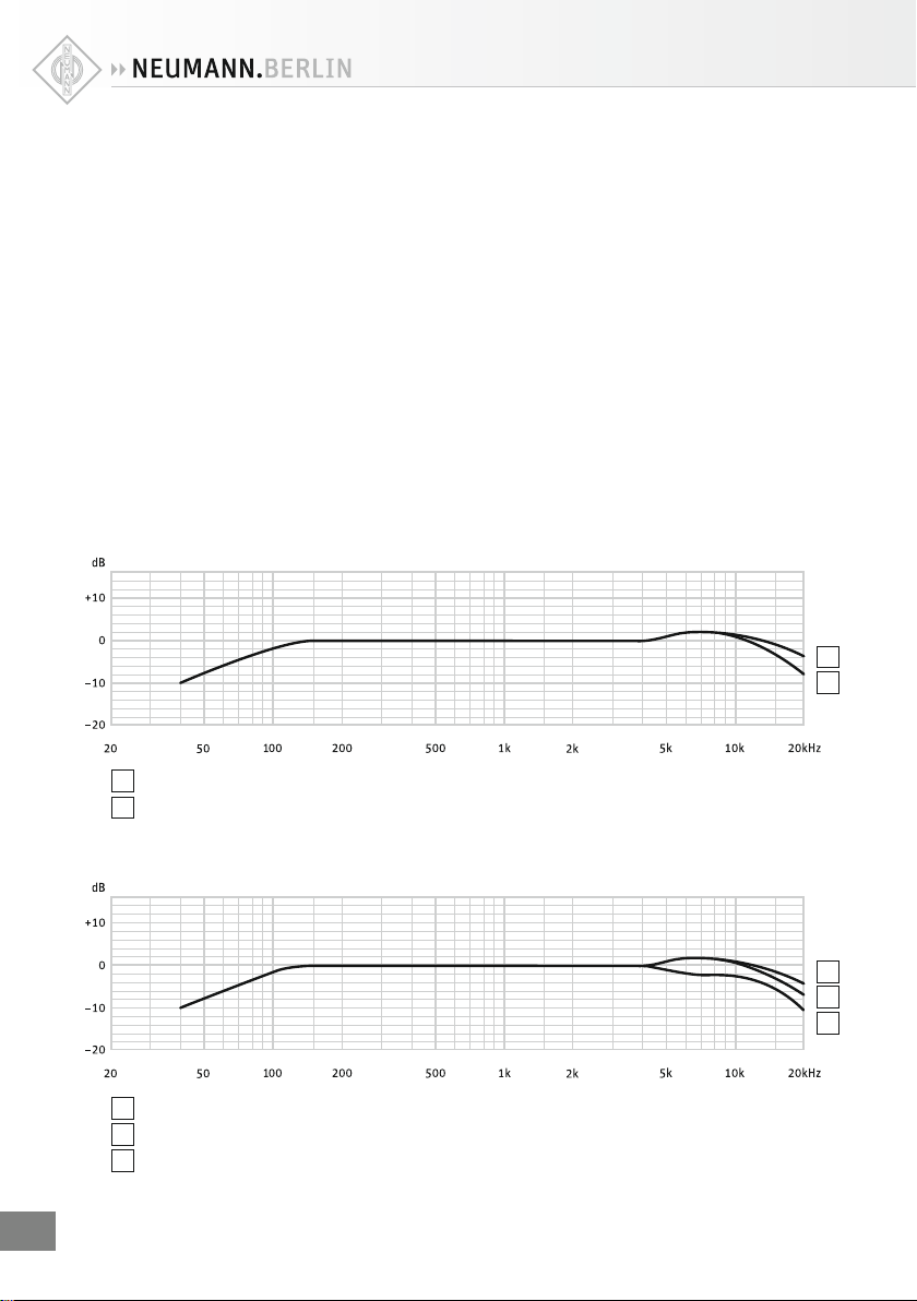
Abb.2
a
b
c
a
= KMR 81 D nx
b
= KMR 81 D nx + Windschutzkorb
c
= KMR 81 D nx + Windschutzkorb + Windjammer
4
D
Page 5

Mit dem Einsatz von Windschutzeinrichtungen ist
immer eine, wenn auch meist geringe, Bedämpfung hoher Frequenzen verbunden. Dieser E ekt
verstärkt sich allerdings, wenn zur Erhöhung der
Wirksamkeit mehrere Windschutzeinrichtungen
miteinander kombiniert werden. Deshalb ist auf
jeden Fall eine Betrachtung der E ektivität solcher Kombinationen angezeigt.
Windschutzeinrichtungen sind um so wirksamer,
je mehr freie Wegstrecke (in gewissen Grenzen)
zwischen ihnen und dem Mikrofon verbleibt. Bei
Verwendung eines Windschutzkorbes sollte der
Raum bis zum Mikrofon wirklich frei sein! Eine
zusätzliche Verwendung des Windschutzes WS81
würde nicht nur den Windschutze ekt herabsetzen, sie würde darüber hinaus die hohen Frequenzen unnötigerweise stark bedämpfen.
Die abgebildeten Kombinationen (Abb. 1/2) stellen zwei wirkungsvolle Varianten für jeweils
unterschiedlich starken Windeinfall bei gleichzeitiger geringst möglicher Frequenzbeeinträchtigung dar.
5. Außerbetriebnahme und Aufbewahrung
Verringern Sie vor der Außerbetriebnahme und
dem Abziehen von Kabeln den Lautstärkepegel
Ihres weiterverarbeitenden Gerätes.
Ziehen Sie beim Lösen von Kabeln stets nur an
den Steckverbindern und nicht am Kabel.
Mikrofone, die nicht im Einsatz sind, sollte man
nicht auf dem Stativ einstauben lassen. Wird ein
Mikrofon längere Zeit nicht verwendet, sollte es
bei normalem Umgebungsklima staubgeschützt
au ewahrt werden. Verwenden Sie hierfür einen
nicht fusselnden, lu durchlässigen Staubschutzbeutel, die Originalverpackung des Mikrofons
oder den mitgelieferten Drehpack.
6. Technische Daten
Zulässige klimatische Verhältnisse:1)
Betriebstemperaturbereich .............. 0 °C … +40 °C
Lagerungstemperaturbereich........–20 °C … +70 °C
Feuchtebereich ......................0 % … 90 % rel. hum.
bei +20 °C
0 % … 85 % rel. hum.
bei +60 °C
Akust. Arbeitsweise ............Interferenzempfänger
Richtcharakteristik .................... Superniere/Keule
Übertragungsbereich ......................20 Hz...20 kHz
Feldübertragungsfaktor2) ........................ –36 dBFS
Ersatzgeräuschpegel,
CCIR4) ............................................................... 21 dB
Ersatzgeräuschpegel,
A-bewertet4) ..................................................9 dB-A
Geräuschpegelabstand3),
CCIR4) ...............................................................73 dB
Geräuschpegelabstand3),
A-bewertet4) ....................................................85 dB
Grenzschalldruckpegel
bei 0 dBFS3) ........................................... 123 dB SPL
Grenzschalldruckpegel
mit 18 dB Vordämpfung (RC S)3) ............ 141 dB SPL
Dynamikumfang, A-bewertet3): ................... 114 dB
A/D -Wandlung ........................Neum ann-Verfahren
(patentiert), 28 Bit
interne Wortbreite
Digitale Signalverarbeitung....... Fixpoint, variable
interne Wortbreite,
28...60 Bit
Abtas traten ...................................... 44,1 /48/88, 2/
96/176,4/192 kHz
Ausgangsdatenformat ...........24 Bit nach AES/EBU
(AES3)
Latenzzeit:
44,1/48 kHz .......................................... 41 Samples
88,2/96 kHz .......................................... 49 Samples
176,4/192 kHz ....................................... 99 Samples
Synchronisation:
freilaufend (nicht synchronisiert),
Frequenz-Grundgenauigkeit .................... ± 25 ppm
synchroner Betrieb,
Ziehbereich ....................................min. ± 100 ppm
Stromversorgung
(Phantomspeisung gemäß AES42)
Arbeitsspannungsbereich.................... +7...+10,5 V
Stromaufnahme ....................... max. 150 mA (DPP)
5
D
Page 6

Steckve rbinder ............................................ XLR 3 M
Abmessungen ...................................Ø 22 x 212 mm
Gewic ht ............................................................. 90 g
Fernsteuerbare Funktionen
Vordämpfung .............................. 0/–6/–1 2/–18 d B
Hochpass lter ...........................O /40/80/160 Hz
Digitale Signalverstärkung ...............0...10...63 dB
Testsignal ............................Off , 1 kHz (–48 dBFS),
Kompres sor/Limiter ..................................... On/O
Untere Grenzfrequenz
des Arbeitsbereichs ........... fl at/1 kHz/2 kHz/4 kHz
Max . Dämpfung (gain reduc tion):
at mode ....................................................... > 63 dB
1 kHz/2 kHz/4 kHz ........................................ > 20 dB
Ratio ............................................... 1, 2:1/1 ,5:1 /2:1/
Thresh old ........................ –63 d BFS..–10...0 dBFS,
Attack time ............. 0/0,1/0,3/1/3/10/30/100 ms
Release time ..................0,05/0,1/0,2/0,5/1/ 2/5 s
(bezo gen auf eine Peg eländerun g von ca. 10 dB )
Peak-Limit er .................................................. On/O
Attack time ...................................–160 μs (negativ)
Release time ............................. ca. 50 ms...150 ms
Thresh old ........................................O : 0 dBFS fest
Mute ............................................................... On/Off
Phase (Polarität)..........................................0, 180°
Anzeige ................................................... LED (bl au),
Abtas traten ..................................... 44 ,1/48/88,2/
in 1 dB-Schritten, knackfrei
rosa Rauschen (–35 dBFS),
weißes Rau schen (–43 dBF S)
3:1/4:1/6:1/8:1/>100:1
in 1 dB Stufen
(signalabhängig)
On: –15 dBFS...0 dBFS,
in 1 dB-Stufen
Helligkeit einstellbar
(Werkseinste llung je nach Variante)
96/176,4/192 kHz
7. Zubehör* (Fotos im Anhang)
Connection Kits & Interface
Connection Kit AES/EBU............ Best.-Nr. 008584
Connection Kit S/PDIF ...............Best.-Nr. 008585
Interface DMI-2 portable ...........Best.-Nr. 542404
Interface DMI-8 ..........................Best.-Nr. 5331 30
Elastische Aufhängungen
EA 2124 A mt ...........sw ...............Best.-Nr. 008433
Mikrofonneigevorrichtung
MNV 21 mt ...............sw ............... Best.-Nr. 006802
Stativgelenke
SG 21 bk ...................sw ............... Best.-Nr. 008613
Windschutz-Sets
WKE 81 Set ..............gr ................Best.-Nr. 53938 1
Schaumstoff windschutz
WS81 .......................sw ............... Best.-Nr. 007268
Bedeutung der Farbcodierungen:
ni = nickel, nx = nextel, sw = schwarz, gr = grau
* Ausführlic he Beschr eibungen un d weitere Ar tikel nden Sie
i n u n s e r e m Z u b e h ö r k a t a l o g o d e r u n t e r w w w . n e u m a n n . c o m
Bei 0 dB Vordämp fung und 0 dB Gain.
1)
Alle Werte für nicht-kondensierende Feuchtigkeit.
2)
bei 1 kHz , 0 dB Verstärk ung und 94 dB SPL
3)
be zogen auf 94 dB SPL
4)
na ch IEC 60268 -1;
CCIR-Bew ertung nach CCIR 468-3, Qua si-Spitzenwert;
A-Be wertung na ch IEC 61672-1, E ektivwert
Werkseinstellungen sind fett gekennzeichnet. Diese können
bei Verwendung eines DMI mit der Remote Control So ware
jederzeit geändert werden.
6
D
Page 7

8. Lieferumfang
Mikrofon
Mikrofon KMR 81 D nx
Windschutz WS 81
Drehpack
Bedienungsanleitung
9. Fehlercheckliste
Fehler
Keine
Funktion /
Keine Signalübertragung
Ton verzerrt /
schlechte
Signalqualität
Keine
Synchronisation
Mögliche Ursachen
▶
Speisespannung fehlt Überprüfen Sie das Speisegerät und ggf. die
Das Mikrofon ist nicht mit einem
AES42-Eingang verbunden
Das Mikrofon ist nicht mit dem
richtigen Kanal verbunden
Der Kanal ist gemutet Deaktivieren Sie in der AES42-Fernsteuerung Mute.
Zu hohe Schalldrücke im
aufzunehmenden Tonsignal
Übersteuerung durch tief-
frequente Störgeräusche
(Trittschall, Wind)
Übersteuerung durch Explosivlaute
Asynchroner Betrieb ist
eingestellt
Sample Rate von Mikrofon und
Folgegerät stimmen nicht überein
Externer Word Clock wird
erkannt, aber lieg t außerhalb der
Spezi kation
Abhilfe
▶
zugehörigen So ware-Einstellungen
(RCS -> System -> MicPWR).
Verwenden Sie einen AES42-Eingang.
Überprüfen Sie den Signalweg.
Aktivieren Sie ggf. den entsprechenden Eingang auf
dem zugeordneten Kanalzug des Mischpults.
Vergrößern Sie den Aufnahmeabstand. Aktivieren Sie
die Vordämpfung in Ihrer AES42-Fernsteuerung.
Benutzen Sie einen geeigneten Windschutz (Zubehör).
Aktivieren Sie die Vordämpfung in Ihrer AES42Fernsteuerung.
Benutzen Sie einen geeigneten Popschutz (Zubehör).
Aktivieren Sie die Vordämpfung in Ihrer AES42Fernsteuerung.
Wählen Sie den Synchronmode (Mode 2, RCS).
Synchronisieren Sie den digitalen Eingang mit der
Quelle.
Verwenden Sie einen Sample-Rate-Converter.
Überprüfen Sie den externen Wordclock auf Genauig-
keit und Signalqualität (Jitter? Sehr lange Kabel?).
Alternative Abhilfe: Verwenden Sie den internen
DMI-Wordclock als Master Word Clock für die gesamte
Signalkette.
7
D
Page 8

1. Introduction
This manual contain s essential information for the
operation and care of the products you have purchased. Please read the instructions carefully and
completely before using the equipment. Please
keep this manual where it will be accessible at all
times to all current and future users.
Additional information, in particular concerning
available accessories and Neumann service partners, can always be found on our website: www.
neumann.com. Information about service partners can also be obtained by telephone: +49 (0)
30 / 41 7 7 24 - 0.
The following related les are available in PDF
format in the Downloads section of our website
www.neumann.com:
• Some Remarks on Microphone Maintenance
• DMI-2, DMI-2 portable and DMI-8 Digital Microphone Interface Operating Manual
• RCS Remote Control So ware Operating Manual
• Connection Kit Operating Manual
• Short description of the AES42 standard
The newest version of the microphone and DMI
so ware as well as the latest RCS can be found in
the Download sec tion as well.
Additional information concerning the digital
microphone interface can be found in standard
AES42 on the website: www.aes.org/standards
“AES standards for acoustics, Digital interface for
microphones”.
The Neumann online forum on our website enables Neumann users worldwide to share their
experiences. Through its integrated archive function, the forum has developed into an extensive
knowledge pool.
2. Safety instructions
The microphone has the intended purpose of
converting acoustic signals into digital electrical
signals.
Connect the microphone only to microphone
inputs and to equipment which supplies phantom power in accordance with AES42.
But the microphone will not be damaged if it is
accidentally connected to an analog microphone
input with a phantom power of 48 V for a short
period. The KMR 81 D has overvoltage protection
and can handle a voltage of up to +55 V for a short
period.
Repairs and ser vicing are to be carried out only by
experienced, authorized service personnel. Unauthorized opening or modi cation of the equipment shall void the warranty.
Use the microphone only under the conditions described in the Technical Data.
Allow the microphone to adapt to the ambient
temperature before switching it on.
Do not operate the microphone in a damaged condition.
Always run cables in such a way that there is no
risk of tripping over them.
Unless required for operation, ensure that liquids
and electrically conductive objects are kept at a
safe distance from the equipment and its connections.
Do not use solvents or aggressive cleansers for
cleaning purposes.
Dispose of the equipment in accordance with the
regulations applicable to the respective country.
3. Brief description
The KMR 81 D digital microphone is a condenser
microphone of t he So luti on- D family with a d igit al
output that complies with the international standard AES42. Based upon the usual AES3 (AES/
EBU) standard for digital audio signals in studio
equipment, this standard has been extended to
include phantom power for the microphone, remote control and synchronization data, and user
bits for the transmission of microphone information.
With the help of an interference tube in front of
the capsule the directivity is signi cantly improved compared to standard pressure gradient
microphones for mid and higher frequencies.
The microphone features exceptionally clean
sound transmission which is free of coloration,
with very low self-noise and an extensive dynamic
range. Digitization is performed by an A/D conversion process developed and patented by Neumann. This ensures that the full dynamic range
of the capsule signal is transferred to the digital
realm. The integrated digital signal processing
also permits functions to be provided which were
previously available only via the mixing console
EN
8
Page 9

or additional studio equipment. These functions
are described in the “Technical data” section.
If there is no microphone input according to
AES42 standard available Neumann provides
Connec tion Kits for the s impl e supp ly of power, as
well as the two-channel Digital Microphone Interface DMI-2 or DMI-2 portable and the eight-channel DMI-8 with the accompanying RCS control
so ware for remote controlling all microphone
characteristics (see also the “Technic al data” section).
The consumption of power results in slight warming of the microphone, which increases with
shorter cable lengths and higher sampling rates.
4. Setup
Mounting the microphone
Using the mount provided, attach the microphone
to a stable, sturdy stand. If necessary, use an elastic suspension from our range of accessories to
suppress impact sound by means of mechanical
isolation.
Extremely low-frequency signals can result from
interference such as structure-borne noise or pop
and wind noise. In order to suppress such noise
signals, we recommend the use of an elastic suspension, a windscreen or a popscreen, available
as accessories.
Connecting the microphone
Caution: An incorrect supply voltage can dam-
age the microphone!
Connect the microphone to microphone inputs
and to equipment which supplies phantom power in accordance with AES42. See also chapter
“Safety Instructions”.
Caution: Very high signal levels can damage
loudspeakers and your hearing!
Reduce the volume of connected playback equipment before connecting the microphone. This is
also advisable in order to avoid acoustic feedback.
Connect the microphone by means of an XLR
cable to the AES42 microphone input of the DMI
Digital Microphone Interface, to the Neumann
connection kit or to other audio equipment along
to AES42 standard.
Concerning the connection of DMI and Connection Kits with your audio device please consult
the respective operating manuals.
With a correct power supply, a blue LED on the microphone indicates that the microphone is ready
to operate. When the microphone is switched on,
the LED at rst glows dimly, and a er a short time
shines with the preset brightness. When the DMI
Digital Microphone Interface is used, the LED
can be set to four di erent brightness levels and
switched o by means of the Remote Control So ware.
When connecting the cables, ensure that the connectors are locked correctly.
Long cables and multiple connectors lead to deterioration in jitter behavior, particularly in the
case of high sampling rates. Therefore, to the
greatest extent possible, use continuous cable
between the microphone and subsequent equipment, and for longer distances use AES/EBU
cable exclusively (with an impedance level of
110ohms).
Ensure that the microphone and all equipment in
the digital signal chain are synchronized. If the
Neumann Digital Microphone Interface is used,
the connected microphones should always be
operated in synchronous mode, whether or not
sample rate converters are used in the subsequent signal chain. This will ensure very e ective
jitter suppression in the DMI. The output of two
microphone signals in an AES3 stereo signal is
also possible only if the microphones are synchronized with one another.
Sound test
Simply speak into the microphone. Do not blow
into the microphone or subject it to pop noise,
since this can easily result in hazardous sound
pressure levels.
Parameters which can be remote controlled
via the AES42 interface
Low Cut: Acccording to AES42 there are four settings for the low cut: o , 40 Hz, 80 Hz and 160 Hz.
Pre-attenuation: Pre-attenuation is achieved by
reducing the capsule voltage. If pre -attenuation is
activated, the dynamic range is shi ed by the corresponding value to higher sound pressure levels.
Gain: Gain is carried out exclusively in the digital
domain, thus avoiding the additional noise and
9
EN
Page 10

possible e ects on the sound which can occur in
analog processing.
Peak limiter: The very fast peak limiter has an adjustable threshold, and prevents overloading or
clipping of the audio signal in the signal path.
Compressor/Limiter: A compressor/limiter with
completely adjustable parameters is provided.
It can function in broad band mode, or as a highfrequency compressor/limiter (de-esser) in one of
three selectable frequency ranges. All important
parameters are adjustable.
In addition, the sampling rate, the synchronization mode, test signals, mute, the polarity of the
output signal and the LED can be controlled remotely.
Fig. 1
a
= KMR 81 D nx
b
= KMR 81 D nx + WS 81
The so ware in the microphone can be updated
via the Neumann DMI. Therefore future so ware
enhancements will also be available to existing
customers. Please refer to the RCS manual for details concerning the update process.
Recommendation for the Use of Windscreens
in Combination
Di erent kinds of windscreens are available to
avoid problems caused by wind, close talking,
and rapid movements of the microphone (refer to
chapter Accessories).
The application of windscreens causes always
some attenuation of high frequencies, although
mostly minor. This loss is more noticeable when
a combination of more than one screen is used in
a
b
EN
Fig.2
a
= KMR 81 D nx
b
= KMR 81 D nx + Windshield basket
c
= KMR 81 D nx + Windshield basket + Windjammer
10
a
b
c
Page 11

order to increase the amount of protection. lt is
therefore necessary to consider the actual combined e ect of such an arrangement.
Within a certain range the protection of any windscreen increases proportionately with the empty
space between the screen itself and the microphone. For example, using a windscreen the inner space should be clear of anything except the
microphone (and mounting hardware). The additional application of the WS 81 foam windshield
would not only decrease e ciency of the protection but would also reduce high frequencies unnecessarily.
The following illustrations (Fig. 1/2) show two
successful methods of using various windscreen
combinations to adjust to di erent wind disturbances while o ering a minimum reduction in
high frequency response.
5. Shutdown and storage
Before switching o the microphone or disconnecting the cables, reduce the volume of connected equipment.
When disconnecting a cable, always pull only on
the connector and not on the cable itself.
Microphones which are not in use should not be
allowed to remain on the stand gathering dust. A
microphone which is unused for a prolonged period should be stored under normal atmospheric
conditions, and should be protected from dust.
For this purpose, use a lint-free, air-permeable
dust cover, the original packaging of the microphone or the included twistpack.
6. Technical data
Permissible atmospheric conditions1)
Operating temperature range .......... 0 °C to +40 °C
Storage temperature range ...........–20 °C to +70 °C
Humidity range .....................0 % to 90 % at +20 °C
0 % … 85 % at +60 °C
Acoustical op. principle ......................Interference
transducer
Directional
patter n ......................................Supe r c a r d ioi d / l o b e
Frequency range ............................ 20 Hz to 20 kHz
Sensitivity2) .............................................. –36 dBFS
Equivalent noise level,
CCIR4) ...............................................................21 dB
Equivalent noise level,
A-weighted4) ................................................. 9 dB -A
Signal-to-noise ratio3),
CCIR4) .............................................................. 73 dB
Signal-to-noise ratio3),
A-weighted4) ................................................... 85 dB
Maximum SPL
at 0 dBFS3) ............................................. 123 dB SPL
Maximum SPL
with 18 dB preatt (RCS)3) ...................... 141 dB SPL
A/D conversion ...........................Neumann process
(patented), 28-bit
internal word length
Digital signal processing ..... Fixed-point, variable
internal word length
28 bits to 60 bits
Sampling rates .................................44.1/48/88.2/
96/176.4/192 kHz
Output data format ............................ 24 bits as per
AES/EBU (AES3)
Latency:
44.1/48 kHz ...........................................41 samples
88.2/96 kHz .......................................... 49 samples
176.4/192 kHz ....................................... 99 samples
Synchronization
Free-running (non-synchronous operation),
frequency stability ................................... ± 25 ppm
Synchronous operation,
pulling range ..................................min. ± 100 ppm
Power supply
(phantom power complying with AES42)
Supply voltage range ....................... +7 V to +10.5 V
Current consumption .............. max. 150 mA (DDP)
11
EN
Page 12

Matching Conn ector .................................... X LR 3 M
Dimensions .......................................Ø 22 x 212 mm
Weight ............................................................... 90 g
Remote controlled functions
Pre-attenuation ..........................0/– 6/–12 /–18 d B
High-pass lter ..........................O /40/80/160 Hz
Digital gain ......................................... 0...10...63 dB
Test signals ..........................Off , 1 kHz (–48 dBFS),
Compre ssor/Limiter ..................................... On/O
Lower cut-o frequency
of the working range ..........Flat/1 kHz/2 kHz/4 kHz
Max. gain reduction:
Flat mode ...................................................... > 63 dB
1 kHz/2 kHz/4 kHz ........................................ > 20 dB
Compression ratio .........................1.2:1/1.5:1/2:1/
Thresh old ........................ –63 d BFS..–10...0 dBFS,
Attack time ............. 0/0.1/0.3/1/3/10/30/100 ms
Release time ..................0.05/0.1/0. 2/0.5/1/2/5 s
Peak limiter ................................................... On/O
Attack time .................................–160 μs (negative)
Release time .................. Approx. 50 ms to 1 50 ms
Thresh old ......................................O : 0 dBFS xed
Mute ............................................................... On/Off
Phase (polarity) ......................................... 0°, 180°
Signal light .............................................LED (blue),
Sampling rates ................................ 44.1/48/88.2/
(Factor y settin g depending o n version supp lied.)
in steps of 1 dB, clickless
Pink noise (–35 dBFS),
White noise (–43 dBFS)
3:1/4:1/6:1/8:1/>100:1
in steps of 1 dB
(for a leve l change of appr ox. 10 dB)
(signal-dependent)
On: –15 dBFS to 0 dBFS,
in steps of 1 dB
brightness adjustable
96/176.4/192 kHz
7. Accessories* (see photos in appendix)
Connection Kits & Interface
Connection Kit AES/EBU..............Cat. No. 008584
Connection Kit S/PDIF .................Cat. No. 008585
Interface, DMI-2 portable ............Cat. No 542404
Interface, DMI-8 ...........................Cat. No. 5331 30
Elastic Suspensions
EA 2124 A mt ...........blk ................Cat. No. 008433
Auditorium Hanger
MNV 21 mt ...............blk ................Cat. No. 006802
Stand Mounts
SG 21 bk ...................blk ................Cat. No. 008613
Windscreen Sets
WKE 81 Set ..............gr ..................Cat. No. 539381
Foam Windscreens
WS 81 ......................blk ................Cat. No. 007268
Meaning of color codes:
ni = nickel, nx = nextel, blk = black, gr = grey
* Detailed descriptions and additional articles can be found
in our acc essorie s catalog or a t: www.neu mann.com
EN
At 0 dB pre -attenuat ion and 0 dB gain .
1)
All valu es are for non -condens ing humidit y.
2)
at 1 kHz, 0 d B gain, and 94 db SP L
3)
re 94 dB SPL
4)
a ccording to IEC 6 0268-1;
CCIR- weighting a ccording to CC IR 468-3, qu asi peak;
A-wei ghting acco rding to IEC 61672 -1, RMS
Factor y settin gs are indica ted in bold. If t he DMI is used , they
can be ch anged at any ti me via the Remo te Control So ware.
12
Page 13

8. Scope of delivery
Microphone
KMR 81 D nx microphone
WS 81 windscreen
Twi st pa ck
Operating manual
9. Troubleshooting
Problem
Microphone not
operating /
No signal
transmission
Distorted
sound /
bad signal
quality
No
synchronization
Possible causes
▶
Supply voltage not ac tivated Check the power supply device and if necessary
The microphone is not connected
to an AES42 input
The microphone is not connected
to the correct channel
The channel is muted Deactivate the mute in the AES42 remote control.
Excessive sound pressure level of
the sig nal to be recor ded
Overload due to low-frequency
interference (e.g. impact sound
or wind)
Overloading due to Plosives Use an appropriate popscreen (accessory). Activate
Operation is set to asynchronous
mode
The sample rates of the microphone and the subsequent equipment do not cor respo nd with one
another
An external word clo ck is
detected but does not conform to
speci cations
Solution
▶
the associated so ware set tings (RC S -> Sys tem ->
MicPWR).
Use an AE S42 input.
Check the signal path.
If necessary, activate the appropriate input on the
corresponding channel of the mixing console.
Increase the recording distance. Activate the pre attenuation in the AES42 remote control.
Use an appropriate windscreen (accessor y). Activate
the pre-attenuation in the AES42 remote control.
the pre-attenuation in the AES42 remote control.
Activate the synchronization of the AES42 input
(mode 2, RC S).
Synchronize the digital input with the source.
Use a sample rate converter.
Check the external word clock for precision and signal
quality (e.g. check for jitter or very long cables).
Alternative solution: Use the internal DMI word clock
as the master word clock for the entire signal chain.
13
EN
Page 14

10. Frequenz- und Polardiagramme
10. Frequency responses and polar patterns
gemessen im freien Schallfeld nach IEC 60268-4, Toleranz ±2 dB
measured in free- eld conditions (IEC 60268-4), tolerance ±2 dB
14
Page 15

Connection Kit S/PDIFConnection Kit AES/EBU Interface DMI-2 portable
Interface DMI-8
SG 21 bk WS 81WKE 81 Set
EA 2124 A mt MNV 21 mt
15
Page 16

Haftungsausschluss
Die Georg Neumann GmbH übernimmt keinerlei Ha ung für Folgen eines
unsac hgemäßen Ge brauchs de s Produkt s, d.h. die F olgen eine s Gebrauch s,
der von de n in der Bedie nungsanle itung genann ten technis chen Voraus setzungen abweicht (z.B. Bedienungsfehler, mechanische Beschädigungen,
falsc he Spannung, A bweichung von em pfohlenen Kor respondenz geräten).
Jegliche Ha ung der Georg Neumann GmbH für Schäden und Folgeschäden, die dem Benutzer aufgrund eines solchen abweichenden Gebrauchs
entstehen sollten, wird ausgeschlossen. Ausgenommen von diesem Haftungsausschluss sind Ansprüche aufgrund zwingender gesetzlicher Haftung, w ie z.B. nac h Produktha ungsgesetz.
Limitation o f Liability
Georg N eumann GmbH sha ll not be liable for c onsequence s of an inappropriate u se of the produ ct not being in c ompliance wi th the technic al allowanc e in t he us er ma nual such a s han dlin g err ors , me chan ical spoi ling , fal se
voltage and using other than the recommended correspondence devices.
Any liabi lity of Georg N eumann GmbH for an y damages inclu ding indirec t,
consequential, special, incidental and punitive damages based on the
user’s non-compliance with the user manual or unreasonable utilization
of the product is hereby excluded as to the extent permitted by law. This
limitation of liability on damages is not applicable for the liability under
European product liability codes or for users in a state or country where
suc h damag es ca nnot b e limit ed.
Konformitätserklärung
Die Geo rg Neumann GmbH erklär t, dass dies es Gerät die anwe ndba-
ren CE- Normen und -Vor schri en erfüllt.
Neuman n ist in zahlre ichen Länd ern eine einge tragene Mar ke der Ge-
®
org Neum ann GmbH.
Declaration of Conformity
Georg Neumann GmbH hereby declares that this device conforms to
the applicable CE standards and regulations.
Neumann is a registered trademark of the Georg Neumann GmbH in
®
certain countries.
Irrtümer und technische Änderungen vorbehalten • Errors excepted, subject to changes
Printed in Germany • Publ. 12/14 541545/A03
 Loading...