

Page 1
KM D
B
O M
Registrieren Sie bitte Ihr
System auf der Website
www.my-Solution-D.com,
um über Updates informiert
zu werden!
Please register your system
on the website
www.my-Solution-D.com,
to be informed whenever updates
are available!
· . · ·
() / - · - · @. · ..
Page 2
1. Einleitung
In dieser Anleitung fi nden Sie alle wichtigen Informationen für den Betrieb und die Pfl ege des von
Ihnen erworbenen Mikrophons. Lesen Sie diese
Anleitung bitte sorgfältig und vollständig, bevor
Sie es benutzen. Bewahren Sie die Anleitung bitte
so auf, dass sie für alle moment anen und späteren
Nutzer jederzeit zugänglich ist.
Weitergehende Informationen, insbesondere
auch zu den verfügbaren Zubehörteilen und den
Neumann-Servicepartnern, fi nden Sie auf unserer
Website www.neumann.com. Die Servicepartner
können Sie auch telefonisch unter +49 (0) 30 /
41 77 24 – 0 erfragen.
Auf unserer Website www.neumann.com fi nden
Sie in der Rubrik Downloads ergänzend folgende
PDF-Dateien:
Hinweise zur Pfl ege des Mikrophons
•
Bedienungsanleitung DMI-2 und DMI-8 (Digi-
•
tales Mikrophon-Interface)
Bedienungsanleitung RCS (Remote Control
•
Software)
Bedienungsanleitung Connection Kit
•
Kurzbeschreibung des Standards AES 42
•
In der Rubrik Downloads steht auch die aktuelle
Version der Mikrophon- und DMI-Software sowie
der RCS zur Verfügung.
Weitergehende Informationen zur Schnittstelle
digitaler Mikrophone fi nden Sie bei www.aes.org/
standards unter „ AES standards for acoustics, Digital interface for microphones“.
Zum weltweiten Erfahrungsaustausch unter
Neumann-Anwendern bieten wir das Neumann
Online-Forum an, das sich durch die integrierte
Archivfunktion zu einem umfangreichen KnowHow-Pool entwickelt hat.
2. Sicherheitshinweise
Der bestimmungsgemäße Gebrauch dieses Mikrophons ist die Wandlung akustischer in digitale
elektrische Signale.
Schließen Sie das Mikrophon nur an Mikrophon-
eingänge und Speisegeräte an, die eine
Phantom speisung nach AES 42 liefern.
Das Mikrophon wird jedoch nicht be schädigt, falls
es versehentlich kurzzeitig an einen analogen
Mikrophoneingang mit 48 V-Phantom speisung
angeschlossen wird. Die KM D-Serie ist gegen
Überspannung geschützt und verträgt kurzzeitig
bis +55 V.
Reparatur- und Servicearbeiten dürfen nur von
•
erfahrenem und autorisiertem Fachpersonal
durchgeführt werden. Wenn Sie das Mikrophon
eigenmächtig öff nen oder umbauen, erlischt
die Gewährleistung.
Verwenden Sie das Mikrophon nur in dem in
•
den Technischen Daten angegebenen Leistungsbereich.
Lassen Sie das Mikrophon auf Umgebungstem-
•
peratur akklimatisieren, bevor Sie es einschalten.
Nehmen Sie das Mikrophon nicht in Betrieb,
•
wenn es besch ädigt ist.
Verlegen Sie Kabel stets so, dass niemand dar-
•
über stolpern kann.
Halten Sie Flüssigkeiten vom Mikrophon und
•
dessen Anschlüssen fern.
Verwenden Sie zum Reinigen keine Lösungs-
•
mittel oder aggressiven Reinigungsmittel.
Entsorgen Sie das Mikrophon nach den Bes tim-
•
mungen Ihres Landes.
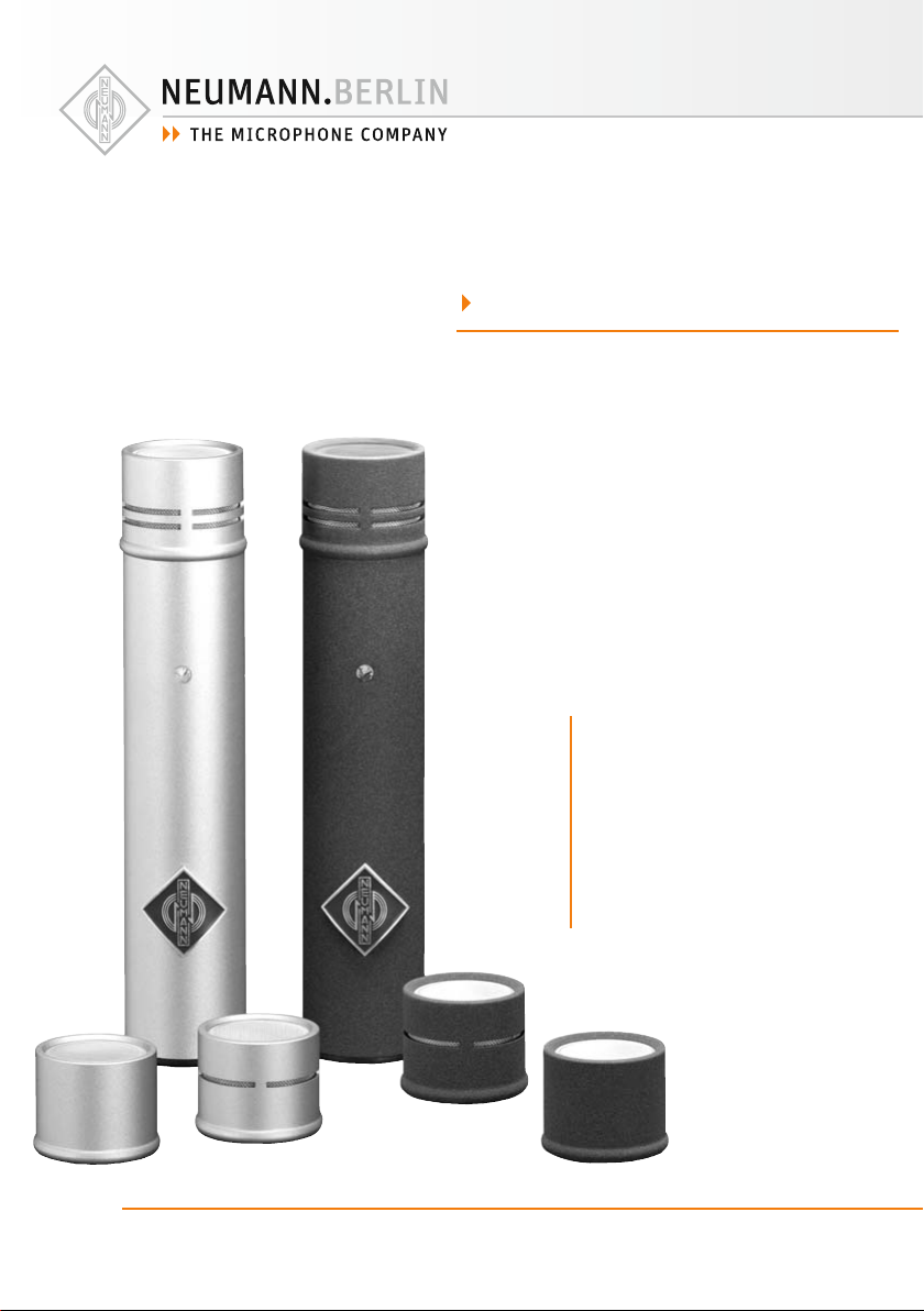
3. Beschreibung
Die digitalen Kleinmikrophone der Solution-DFamilie sind Studio-Kondensatormikrophone mit
digitalem Ausgang gemäß dem internationalen
Standard AES 42. Dieser basiert auf dem in Studiogeräten üblichen Standard AES 3 (AES/EBU)
für digitale Audiosignale, erweitert um die Phantomspeisung für das Mikrophon, um Fernsteuerund Synchronisationsdaten sowie um User-Bits
zum Empfang von Mikrophon-Steuerdaten.
Für die Kleinmikrophone der Solution-D-Serie
bietet Neumann austauschbare Kapseln, diverses
Zubehör und verschiedene Geräte zur Speisung
und Fernsteuerung. Damit wird ein Höchstmaß an
Flexibilität erreicht.
Die Mikrophone zeichnen sich aus durch besonders saubere und verfärbungsfreie Klangübertragung bei sehr niedrigem Eigengeräuschpegel
und gleichzeitig höchster Aussteuerbarkeit. Sie
verwenden zur Digitalisierung ein von Neumann
entwickeltes und patentiertes A/D-Wand lungsverfahren. Dadurch ist sichergestellt, dass der
gesamte Dynamikumfang der Kapselsignale in
die digitale Ebene überführt wird. Mit der inte-
grierten digitalen Signalverarbeitung bieten die
Mikrophone außerdem Funktionen, die bisher nur
im Mischpult oder zusätzlichen Geräten realisiert
werden konnte n. Die se Funk tione n werde n im Kapitel Technische Daten beschr ieben.
Steht zum Anschluss der Mikrophone kein AES 42Eingang (z. B. am Mischpult) zur Verfügung, bietet
Neumann zwei Anschlussmöglichkeiten an: Connection Kits zur reinen Stromversorgung sowie
das zweikanalige Digitale Mikrophon-Interface
DMI-2 und das achtkanalige DMI-8 mit der dazugehörigen Steuersoftware RCS zur Fernsteuerung
aller Mikrophoneigenschaften (siehe auch Kapitel
Technis che D aten).
Die Leistungsaufnahme der Mikrophone führt zu
einer Eigenerwärmung, die mit kleineren Kabellängen und höheren Abtastraten zunimmt.
Die KM D-Kleinmikrophonserie ist ein modulares
System mit austauschbaren Mikrophonkapseln.
Momentan sind folgende Kapseln verfügbar:
KK 131 (nx): Richtcharakteristik Kugel,
freifeld-entzerrt
KK 143 (nx): Richtcharakter istik breite Niere
KK 1 45 (nx): Richtcharakteristik Niere mit Hochpass
KK 183 (nx): Richtcharakter istik Kugel,
diff usfeld-entzerrt
KK 184 (nx): Richtcharakteristik Niere
KK 185 (nx): Richtcharakteristik Hyperniere
Weitere Kapseln werden folgen. Die Kapseln können auch einzeln bezogen werden. Alle Teile sind
jeweils klassisch nickelfarben oder in refl exionsfreier anthrazit-matter Nextelbeschichtung (nx)
erhältlich.
4. Inbetriebnahme
Mikrophon aufstellen
Befestigen Sie das Mikrophon mit der dafür vorgesehenen Halterung auf einem ausreichend stabilen und standfesten Stativ etc. Verwenden Sie
ggf. eine elastische Aufhängung aus unserem Zubehör-Angebot, um Trittschall durch mechanische
Entkopplung zu unterdrücken.
Extrem niederfrequente Signale können durch
Störungen wie Körperschall oder Pop- und Windgeräusche hervorgerufen werden. Um solche
Störsignale zu unterdrücken, empfehlen wir, eine
elastische Aufhängung, einen Windschutz oder
einen Popschirm aus unserem Zubehörprogramm
zu verwenden.
Mikrophon anschließen
Vorsicht: Eine falsche Versorgungsspannung
kann das Mikrophon beschädigen!
Schließen Sie das Mikrophon nur an Mikrophoneingänge und Speisegeräte an, die eine Phantomspeisung nach AES 42 liefern. Siehe auch Kapitel
„Sicherheitshinweise“.
Vorsicht: Sehr hohe Signalpegel können Ihr
Gehör und Ihre Laut sprecher schädigen!
Reduzieren Sie an den angeschlossenen Wiedergabegeräten die Lautstärke, bevor Sie das Mikrophon anschließen, auch wegen der Gefahr der
akustischen Rückkopplung.
Verbinden Sie das Mikrophon über ein XLR-Kabel
mit dem AES 42-Mikrophoneingang Ihres Digitalen Mikrophon-Interface DMI, des Neumann
Connection Kits oder eines anderweitigen Audiogerätes nach AES 42.
Eine blaue LED im Mikrophon zeigt bei korrekter
Speisung die Betriebsbereitschaft an. Sie leuchtet
beim Einschalten zunächst schwach und nach kurzer Zeit mit der voreingestellten Helligkeit. Diese
kann bei Verwendung des Digitalen MikrophonInterfaces DMI mit der Remote Control Software
in vier Stufen variiert und ausgeschaltet werden.
Achten Sie beim Anschließen von Kabeln auf die
korrekte Verriegelung der Steckverbinder.
Lange Kabel und mehrfache Steckverbindungen
führen zu einer Verschlechterung des Jitter-Verhaltens insbesondere bei hohen Abtastraten. Verwenden Sie daher möglichst durchgehende Kabelverbindungen zwischen Mikrophon und Folgegerät und bei größeren Distanzen ausschließlich
AES/EBU-Kabel (Wellenwiderstand 110 Ohm).
Achten Sie darauf, dass das Mikrophon und alle
Geräte der digitalen Signalkette synchronisiert
sind. Wird das Digitale Mikrophon-Interface von
Neumann verwendet, sollten die ange schlossenen
Mikrophone immer im Synchronmode betrieben
werden, unabhängig davon, ob in der nachfolgenden Signalkette Sample Rate Converter im
Einsatz sind. Auf diese Weise wird im DMI eine
sehr eff ektive Jitterunterdrückung wirksam (ab
Hardwarerevision 3). Auch ist die Ausgabe zweier
Mikrophonsignale in einem AES 3-Stereosignal
nur möglich, wenn die Mikrophone untereinander
synchron laufen.
2
D
3
D
Page 3
Parameter, die über die AES 42-Schnittstelle
ferngesteuert werden können
Low Cut: Der Low Cut bietet gemäß AES42-Standard die vier Einstellungen: off , 40 Hz, 80 Hz und
160 Hz.
Vordämpfung: Die Vordämpfung wird durch
Reduktion der Kapselspannung realisiert. Bei
Aktivierung wird der Dynamikbereich um den
entsprechenden Wert zu höheren Schalldrücken
verschoben.
Gain: Die Verstärkung erfolgt ausschließlich auf
der digitalen Ebene und führt damit nicht zu der
aus der analogen Welt bekannten Rauschaddition
und zu möglichen Klangbeeinfl ussungen.
Peak-Limiter: Der sehr schnelle Peak-Limiter hat
eine einstellbare Ansprechschwelle und verhindert Übersteuerungen bzw. Clippen des Audiosignals im Signalweg.
Kompressor/Limiter: Weiterhin ist ein vollständig
parametrisierbarer Kompressor/Limiter implementiert. Dieser kann breitbandig oder als Hochtonkompressor/Limiter (De-Esser) in einem von
drei wählbaren Frequenzbereichen arbeiten. Alle
wichtigen Parameter sind einstellbar.
Außerd em lassen sic h die Abtastra te, der Synchro nisationsmodus, Testsignale, Mute, die Polarität
des Ausgangssignals und die LED fernsteuern.
Die Software im Mikrophon kann über das Neumann DMI ak tualisiert werden, so dass zukünftige
Erweiterungen der Software auch bestehenden
Kunden zur Verfügung stehen werden. Zu Details
des Updatevorganges lesen Sie bitte die RCS-Anleitung.
5. Außerbetriebnahme und Aufbewahrung
Verringern Sie vor der Außerbetriebnahme und
dem Abziehen von Kabeln den Lautstärkepegel
Ihres weiterverarbeitenden Gerätes.
Ziehen Sie beim Lösen von Kabeln stets nur an
den Steckverbindern und nicht am Kabel.
Mikrophone, die längere Zeit nicht verwendet
werden, sollten bei normalem Umgebungsklima
staubgeschützt aufbewahrt werden. Verwenden
Sie hierfür einen nicht fusselnden, luftdurchlässigen Staubschutzbeutel oder die Originalverpackung des Mikrophons.
6. Technische Daten
Zulässige klimatische Verhältnisse:1)
Betriebstemperaturbereich ..............0 °C … +40 °C
Lagerungstemperaturbereich ...... –20 °C … +70 °C
Feuchteb ereich ......................0 % … 90 % rel. hum.
0 % … 85 % rel. hum.
Akust. Arbeitsweise ...... Druck-/Druckgradienten-
Richtcharakteristik
Über tragun gsbere ich ...................... 20 Hz. ..20 kHz
Feldübertragungs-
faktor2) ............................................. –41/–39/–40/
Ersatzgeräuschpegel,
CCIR4) ...................................................... 24/24/24/
Ersatzgeräuschpegel,
A-bewertet4) ............................................13/13/14/
Geräuschpegelabstand3),
CCIR4) ......................................................70/70/70/
Geräuschpegelabstand3),
A-bewertet4) ...........................................81/81/80/
Grenzschalldruckpegel
bei 0 dBFS3) ...................................... 135/13 3/134 /
A/D -Wandlung ........................Neuma nn-Verfahre n
Digitale Signalverarbeitung ...... Fixpoint, variable
Abtas traten ...................................... 44,1 /48/88 ,2/
Ausgangsdatenformat ...........24 Bit nach AES/EBU
Latenzzeit:
44,1/48 kHz .......................................... 41 Samples
88,2/96 kHz .......................................... 49 Samples
176,4/192 kHz ..........................99 Samples (AES 3)
5)
....... Kugel, freifeld -entzerr t/
Niere mit Hochpass/
Kugel, diff usfeld-entzerrt/
Niere/Hyperniere
–41/–39/–42 dBFS
25/22/25 dB
13/13/16 dB-A
69/70/69 dB
81/81/78 dB
135/133/136 dBSPL
(patentiert), 28 Bit
interne Wortbreite
interne Wortbreite,
96/176,4/192 kHz
bei +20 °C
bei +60 °C
empfänger
breite Niere/
28...60 Bit
(AES 3)
Synchronisation:
freilaufend (nicht synchronisiert),
Frequenz-Grundgenauigkeit .................... ± 25 ppm
synchroner Betrieb,
Ziehbereich ....................................min. ± 100 ppm
Stromversorgung
(Phantomspeisung gemäß AE S 42
Arbei tsspannung sbereich) .................. +7...+10,5 V
Stromaufnahme ..................................max. 150 mA
Steckv erbinder ............................................ XLR 3 M
Abmessungen .................................. Ø 22 x 108 mm
Gewic ht ..................................................8 0/84/88 /
80/84/88 g
Fernsteuerbare Funktionen
Vordämpfung ..............................0/– 6/–12 /–18 d B
Hochpassfi lter ...........................Off /4 0/8 0/16 0 Hz
Digitale Signalverstärkung ...............0...10...63 dB
Testsignal ............................Off , 1 kHz (–48 dBFS),
Kompre ssor/Limiter ..................................... On/Off
Untere Grenzfrequenz
5)
des Arbeitsbereichs ........... fl at/1 kHz/2 kHz/4 kHz
Max. Dämpfung (gain reduction):
in 1 dB-Schritten, knackfrei
rosa Rauschen (–35 dBFS),
weißes Rau schen (–43 dBF S)
fl at mode ....................................................... > 63 dB
Bei 0 dB Vordämp fung und 0 dB Gain.
1)
Alle Werte für nicht-kondensierende Feuchtigkeit.
2)
be i 1 kHz, 0 dB Ve rstärkun g und 94 dB SPL
3)
be zogen auf 94 dB SPL
4)
nach IEC 60268-1;
5)
5)
CCIR-Bew ertung nach CCIR 468-3, Qua si-Spitzenwert;
A-B ewertung na ch IEC 61672-1 , Eff ektivwert
5)
gi lt für KM D + KK 13 1 / KM D + KK 143 / KM D + KK 1 45 /
KM 1 83 D / KM 1 84 D / K M 185 D
1 kHz/2 kHz/4 kHz ........................................ > 20 dB
Ratio ............................................... 1, 2:1/ 1,5:1 /2:1/
3:1/4:1/6:1/8:1/>100:1
Thresh old ........................ –63 dBFS..–10...0 dBFS,
in 1 dB Stufen
Attack time ............. 0/0,1/0, 3/1/3/10/30/100 ms
Release time ..................0,05/0,1/0,2/0,5/1/2 /5 s
(bezo gen auf eine Peg eländeru ng von ca. 10 dB )
Peak-Limiter.................................................. On/Off
Attack time ...................................–160 µs (negativ)
Release time ............................. ca. 50 ms...1 50 ms
5)
Thresh old ........................................Off : 0 dBFS fest
(signalabhängig)
On: –15 dBFS...0 dBFS,
5)
Mute ............................................................... On/Off
in 1 dB-Stufen
Phase (Polarität) .........................................0, 180°
5)
Anzeige ..................................................LED (blau),
Helligkeit einstellbar
Abtas traten ...................................... 44,1 /48/88 ,2/
5)
Werkseinstellungen sind fett gekennzeichnet. Diese können
bei Verwendung des DMI mit der Remote Control Software
jeder zeit geände rt werden.
(Werkseinstellung je nach Variante)
96/176,4/192 kHz
4
D
5
D
Page 4
7. Zubehör* (Fotos im Anhang)
Connection Kits & Interface
Connection Kit AES/EBU............ Best.-Nr. 008584
Connection Kit S/PDIF ...............Best.-Nr. 008585
Interface DMI-2 (EU) ..................Best.-Nr. 008561
Interface DMI-2 (UK) .................. Best.-Nr. 008587
Interface DMI-2 (US) .................. Best.-Nr. 008588
Interface DMI-8 (EU) ..................Best.-Nr. 5331 30
Interface DMI-8 (UK) ................. Best.-Nr. 533 13 2
Interface DMI-8 (US) .................. Best.-Nr. 5 33131
Kapseln
KK 131 ......................ni ................Best.-Nr. 008591
KK 131 nx .................nx ...............Best.-Nr. 008592
KK 143 .....................ni ................Best.-Nr. 008593
KK 143 nx ................nx ...............Best.-Nr. 008594
KK 145 .....................ni ................Best.-Nr. 008595
KK 145 nx ................nx ...............Best.-Nr. 008596
KK 183 .....................ni ................Best.-Nr. 008566
KK 183 nx ................nx ...............Best.-Nr. 008567
KK 184 .....................ni ................Best.-Nr. 008568
KK 184 nx ................nx ...............Best.-Nr. 008569
KK 185 .....................ni ................Best.-Nr. 008570
KK 185 nx ................nx ...............Best.-Nr. 008571
Ausgangsstufen
KM D (44,1 kHz) ......ni ................Best.-Nr. 008578
KM D nx (44,1 kHz) .nx ...............Best.-Nr. 008581
KM D (48 kHz) .........ni ................ Best.-Nr. 008579
KM D nx (48 kHz) ....nx ............... Best.-Nr. 008582
KM D (96 kHz) .........ni ................Best.-Nr. 008580
KM D nx (96 kHz) ....nx ...............Best.-Nr. 008583
Elastische Aufhängungen
DA-K M ...................... s w ............... Be s t.-Nr. 008420
EA 21 24 A mt ...........sw ...............B est.- Nr. 008433
Tischständer, Schwanenhälse
MF 2 ..........................sw ............... Bes t.-Nr. 0072 66
MF 3 .........................sw ............... Best.-Nr. 0073 21
SMK 8 i ..................... sw ...............B est.- Nr. 0061 81
Mikrophonneigevorrichtung
MNV 21 mt ................sw ............... Bes t.-Nr. 006802
Stativgelenke, weitere mechanische Adapter
DS 120 .....................s w ...............Be st.-Nr. 007 343
SG 21 bk ...................sw ............... Bes t.-Nr. 008 613
SG 109 .....................sw ............... Best.-Nr. 008614
SG 110 nx .................nx ............... Best .-Nr. 008 611
Schaumstoff windschutz
WNS 100 ..................sw ...............B est.- Nr. 0073 23
WNS 110 ..................sw ............... Best .-Nr. 0085 35
WS 100 .................... sw ...............B est.- Nr. 0067 51
Popschutz
PS 15 .......................sw ...............Best.-Nr. 008472
Anschlusskabel
IC 3 mt .....................sw ............... Best.-Nr. 006543
LC 4 (5 m) ................nx ............... Best.-Nr. 008606
LC 4 (10 m) ..............nx ...............Best.-Nr. 008607
Kapselverlängerungen
KVG 130 nx .............nx ............... Best.-Nr. 008608
KVG 160 nx .............nx ...............Best.-Nr. 008609
KVG 1120 nx ............nx ...............Best.-Nr. 008610
Bedeutung der Farbcodierungen:
ni = nickel, nx = nextel, sw = schwarz, gr = grau
* Ausführliche Beschreibungen und weitere Artikel fi nden Sie
in unserem Zubehörkatalog oder unter www.neumann.com
8. Lieferumfang
Mikrophon Mikrophon Stereo-Set Ausgangsstufe Starter-Set
Mikrophon KM 1xx D (nx) 2 Mikrophone
KM 1xx D (nx)
Stativgelenk SG 21 bk 2 Stativgelenke SG 21 bk Stativgelenk SG 21 bk Stativgelenk SG 21 bk
Windschutz WNS 100 2 Windschutze WNS 100 Windschutz WNS 100 Windschutz WNS 100
Bedienungsanleitung Bedienungsanleitung Bedienungsanleitung Connection Kit
Holzetui Holzetui Holzetui Bedienungsanleitung
Mikrophonausgangsstufe KM D (nx)
Mikrophon KM 184 D nx
Holzetui
9. Fehlercheckliste
Fehler
Keine
Funktion /
Keine Signalübertragung
Ton verzer rt /
schlechte
Signalqualität
Keine
Synchronisation
Mögliche Ursachen
▶
Speisespannung fehlt Überprüfen Sie das Speisegerät und ggf. die
Das Mikrophon ist nicht mit
einem AES 42-Eingang verbunden
Das Mikrophon ist nicht mit dem
richtigen Kanal verbunden
Der Kanal ist gemutet Deaktivieren Sie in der AES 42-Fernsteuerung Mute.
Zu hohe Schalldrücke im
aufzunehmenden Tonsignal
Übersteuerung durch tief-
frequente Störgeräusche
(Trittschall, Wind)
Übersteuerung durch Explosivlaute
Asynchroner Betrieb ist
eingestellt
Sample Rate von Mikrophon und
Folgegerät stimmen nicht überein
Externer Word Clock wird
erkannt, aber liegt außerhalb der
Spezifi kation
Abhilfe
▶
zugehör igen Software-Einstellungen
(RCS -> System -> MicPWR).
Verwenden Sie einen AES 42–Eingang.
Überprüfen Sie den Signalweg.
Aktivieren Sie ggf. den entsprechenden Eingang auf
dem zugeordneten Kanalzug des Mischpults.
Vergrößern Sie den Aufnahmeabstand oder aktivieren
Sie die Vordämpfung in Ihrer AES 42-Fernsteuerung.
Benutzen Sie einen geeigneten Windschutz (Zubehör).
Aktivieren Sie die Vordämpfung in Ihrer AE S 42-Fernsteuerung.
Benutzen Sie einen geeigneten Popschutz (Zubehör).
Aktivieren Sie die Vordämpfung in Ihrer AE S 42-Fernsteuerung.
Wählen Sie den Synchronmode (Mode 2, RCS).
Synchronisieren Sie den dig italen Eingang mit der
Quelle.
Verwenden Sie einen Sample -Rate-Converter.
Überprüfen Sie den externen Wordclock auf Genauig-
keit und Signalqualität (Jitter? Sehr lange Kabel?).
Alternative Abhilfe: Ver wenden Sie den internen
DMI-Wordclock als Master Word Clock für die gesamte
Signalkette.
6
D
7
D
Page 5

1. Introduction
This manual contains essential information for the
operation and care of the microphone you have
purchased. Please read the instructions carefully
and completely before using the product. Please
keep this manual where it will be accessible at all
times to all current and future users.
Additional information, in particular concerning available accessories and Neumann service
partners, can be found on our website: www.neumann.com. Information about service partners
can also be obtained by telephone: +49 (0) 30 /
41 7 7 24 - 0.
The following related fi les are available in PDF
format in the Downloads section of our website
www.neumann.com:
•
Some Remarks on Microphone Maintenance
•
DMI-2 and DMI-8 Digital Microphone Interface
Operating Manual
•
RCS Remote Control Software Operating Manual
•
Connection Kit Operating Manual
•
Short description of the AES 42 standard
The newest version of the microphone and DMI
software as well as the latest RCS can be found in
the Download sec tion as well.
Additional information concerning the digital
microphone interface can be found in standard
AES 42 on the website: www.aes.org/standards
“AES standards for acoustics, Digital interface for
microphones”.
The Neumann online forum enables Neumann
users worldwide to share their experiences.
Through its integrated archive fun ction, the for um
has developed into an extensive knowledge pool.
2. Safety instructions
The microphone has the intended purpose of
converting acoustic signals into digital electrical
signals.
Connect the microphone only to microphone
inputs and to equipment which supplies phantom power in accordance with AES 42.
But the microphone will not be damaged if it is
accidentally connected to an analog microphone
input with a phantom power of 48 V for a short
period. The KM D series has overvoltage protection and can handle a voltage of up to +55 V for a
short period.
Repairs and servicing are to be carried out only
•
by experienced, authorized service personnel.
Unauthorized opening or modifi cation of the
microphone shall void the warranty.
Use the microphone only under the conditions
•
descr ibed in the Technical Data.
Allow the microphone to adapt to the ambient
•
temperature before switching it on.
Do not operate the microphone in a damaged
•
condition.
Always run cables in such a way that there is no
•
risk of tripping over th em.
Ensure that liquids are kept at a safe distance
•
from the microphone and its connec tions.
Do not use solvents or aggressive cleansers for
•
cleaning purposes.
Dispose of the microphone in accordance with
•
the regulations applicable to the respective
country.
3. Description
The digital miniature microphones of the Solution-D family are studio condenser microphones
with a digital output that complies with the international standard AES 42. Based upon the
usual AES 3 (AES/EBU) standard for digital audio
signals in studio equipment, this standard has
been extended to include phantom power for the
microphone, remote control and synchronization
data, and user bits for the receipt of microphone
control data.
In order to maximize fl exibility, for the miniature
microphones of the Solution-D series, Neumann
provides interchangeable capsules, various accessories, and power supply and remote control
equipment.
The microphones feature exceptionally clean
sound transmission which is free of coloration,
with ver y low self-noise and an extensive dynamic
range. Digitization is performed by an A/D conversion process developed and patented by Neumann. This ensures that the full dynamic range
of the capsule signal is transferred to the digital
realm. The integrated digital signal processing
also permits functions to be provided which were
previously available only via the mixing console
or additional studio equipment. These functions
are described in the “Technical data” section.
If there is no microphone input according to
AES 42 standard available Neumann provides
Connection Kits for the simple supply of power, as
well as the two-channel Digital Microphone Interface DMI-2 and the eight-channel DMI-8 with the
accompanying RCS control software for remote
controlling all microphone characteristics (see
also the “Technical data” section).
The consumption of power results in slight warming of the microphone, which increases with
shorter cable lengths and higher sampling rates.
The KM D microphone series is a modular system
which allows to change capsules with diff erent
characteristics. The following capsules are currently available:
KK 131 (nx): Omni free fi eld equalized
characteristic
KK 143 (nx): Cardioid w ide angle characteristic
KK 145 (nx): Cardioid low frequency roll-off
characteristic
KK 183 (nx): Omni diff use fi eld equalized
characteristic
KK 184 (nx): Cardioid characteristic
KK 185 (nx): Hypercardioid characteristic
Additional capsules will follow. The capsules can
also be ordered separately. All par ts are available
in classic satin nickel fi nish or with a non refl ective bl ack nexte l fi nish (nx).
4. Setup
Mounting the microphone
Using the mount provided, attach the microphone
to a stable, sturdy stand. If necessary, use an elastic suspension from our range of accessories to
suppress impact sound by means of mechanical
isolation.
Extremely low-frequency signals can result from
interference such as structure-borne noise or pop
and wind noise. In order to suppress such noise
signals, we recommend the use of an elastic suspension, a windscreen or a popscreen, available
as accessories.
Connecting the microphone
Caution: An incorrect supply voltage can dam-
age the microphone!
Connect the microphone to microphone inputs
and to equipment which supplies phantom power in accordance with AES 42. See also chapter
“Safety Instructions”.
Caution: Very high signal levels can damage
loudspeakers and your hearing!
Reduce the volume of connected playback equipment before connecting the microphone. This is
also advisable in order to avoid acoustic feedback.
Connect the microphone by means of an XLR
cable to the AES 42 microphone input of the DMI
Digital Microphone Interface, to the Neumann
connection kit or to other audio equipment along
to AES 42 standard.
With a correct power supply, a blue LED on the microphone indicates that the microphone is ready
to operate. When the microphone is switched on,
the LED at fi rst glows dimly, and after a short time
shines with the preset brightness. When the DMI
Digital Microphone Interface is used, the LED
can be set to four diff erent brightness levels and
switched off by means of the Remote Control Software.
When connecting the cables, ensure that the connectors are locked correctly.
Long cables and multiple connectors lead to deteri ora tio n in j itt er b ehavi or, p art icu lar ly in the cas e
of high sampling rates. Therefore, to the greatest
extent possible, use continuous cable between
the microphone and subsequent equipment, and
for longer distances use AES/EBU cable e xclusively (with an impedance level of 110 ohms).
Ensure that the microphone and all equipment in
the digital signal chain are synchronized. If the
Neumann Digital Microphone Interface is used,
the connected microphones should always be
operated in synchronous mode, whether or not
sample rate converters are used in the subsequent signal chain. This will ensure very eff ective
jitter suppression in the DMI (as of hardware version 3). The output of two microphone signals in
an AES 3 stereo signal is also possible only if the
microphones are synchronized with one another.
EN
8
9
EN
Page 6

Parameters which can be remote controlled
via the AES 42 interface
Low Cut: According to AES42 there are four settings for the low cut: off , 40 Hz, 80 Hz and 160 Hz.
Pre-attenuation: Pre-attenuation is achieved by
reducing the capsule voltage. If pre-attenuation is
activated, the dynamic range is shifted by the corresponding value to higher sound pressure levels.
Gain: Gain is carried out exclusively in the digital
domain, thus avoiding the additional noise and
possible eff ects on the sound which can occur in
analog processing.
Peak limiter: The very fast peak limiter has an adjustable threshold, and prevents overloading or
clipping of the audio signal in the signal path.
Compressor/Limiter: As well, a compressor/limiter with completely adjustable parameters is
provided. It can function in a broad band, or as
a high-frequency compressor/limiter (de-esser)
in one of three selectable frequency ranges. All
important parameters are adjustable.
In addition, the sampling rate, the synchronization mode, test signals, mute, the polarity of the
output signal and the LED can be controlled remotely.
The software in the microphone can be updated
via the Neumann DMI. Therefore future software
enhancements will also be available to existing
customers. Please refer to the RCS manual for details concerning the update process.
5. Shutdown and Storage
Before switching off the microphone or disconnecting the cables, reduce the volume of connected equipment.
When disconnecting a cable, always pull only on
the connector and not on the cable itself.
Microphones which are unused for prolonged
periods should be stored under normal ambient
atmospheric conditions, and should be protected
from dust. For this purpose, use a lint-free, airpermeable dust cover or the original packaging of
the microphone.
6. Technical data
Permissible atmospheric conditions1)
Operating temperature range .......... 0 °C to +40 °C
Storage temperature range ...........–20 °C to +70 °C
Humidity range .....................0 % to 90 % at +20 °C
Acoustical op. principle ............Pressure/pressure
Directional
5)
pattern
......................... Omni free fi eld equalized/
cardioid low frequency roll-off /
Frequency range ............................ 20 Hz to 20 kHz
Sensitivity2) ..................................... –41/–39/–40/
Equivalent noise level,
CCIR4) ...................................................... 24/24/24/
Equivalent noise level,
A-weighted4) ............................................13/13/14/
Signal-to-noise ratio3),
CCIR4) ......................................................70/70/70/
Signal-to-noise ratio3),
A-weighted4) ...........................................81 /81/80/
Maximum SPL
at 0 dBFS3) ....................................... 135/133/134/
A/D conversion ...........................Neumann process
Digital signal processing ..... Fixed-point, variable
Sampling rates .................................44.1/48/88.2/
Output data format ............................24 bits as per
Latency:
44.1/48 kHz ...........................................41 samples
88.2/96 kHz .......................................... 49 samples
176.4/192 kHz ..........................99 samples (AES 3)
0 % … 85 % at +60 °C
gradient transducer
cardioid wide angle/
omni diff use fi eld equalized/
cardioid/hypercardioid
–41/–39/–42 dBFS
25/22/25 dB
13/13/16 dB-A
69/70/69 dB
81/81/78 dB
135/133/136 dBSPL
(patented), 28-bit
internal word length
internal word length
28 bits to 60 bits
96/176.4/192 kHz
AES/EBU (AE S 3)
Synchronization
Free-running (non-synchronous operation),
frequency stability ................................... ± 25 ppm
Synchronous operation,
pulling range ..................................min. ± 100 ppm
Power supply
(phantom power complying with AE S 42)
Supply voltage range .......................+7 V to +10.5 V
Current consumption .........................Max. 1 50 mA
Connec tor ..................................................... XL R 3 M
Dimensions ......................................Ø 22 x 108 mm
Weight ..............................80/8 4/88/80/ 84/88 g
At 0 dB pre -attenua tion and 0 dB ga in.
1)
All valu es are for non -conden sing humidit y.
2)
at 1 kHz, 0 d B gain, and 94 db S PL
3)
re 94 dB SPL
4)
5)
5)
accord ing to IEC 6026 8-1;
CCIR- weighting a ccording to CC IR 468-3 , quasi peak;
A-wei ghting acc ording to IEC 6167 2-1, RMS
5)
For K M D + KK 131 / KM D + KK 1 43 / KM D + KK 145 /
KM 1 83 D / KM 1 84 D / K M 185 D
5)
Remote controlled functions
Pre-attenuation ..........................0/– 6/–12 /–18 dB
High-pass fi lter ..........................Off /40/ 80/1 60 Hz
Digital gain .........................................0...10...63 dB
Test signal s ..........................Off , 1 kHz (–48 dBFS),
Compre ssor/Limite r ..................................... On/Off
6)
Lower cut-off frequency
of the working range ..........Flat/1 kHz/2 kHz/4 kHz
Max. gain reduction:
Flat mode ...................................................... > 63 dB
1 kHz/2 kHz/4 kHz ........................................ > 20 dB
Compression ratio .........................1.2:1/1.5:1/2:1/
Thresh old ........................ –63 dBFS..–10...0 dBFS,
Attack time ............. 0/0.1/0.3/1/3/10/30/100 ms
Release time ..................0.05/0.1/0.2/0.5/1/ 2/5 s
Peak limiter ................................................... On/Off
Attack time .................................–160 µs (negative)
in steps of 1 dB, clickless
Pink noise (–35 dBFS),
White noise (–43 dBFS)
3:1/4:1/6:1/8:1/>100:1
in steps of 1 dB
(for a level change of approx. 10 dB)
Release time .................. Approx. 50 ms to 150 ms
5)
Thresh old ......................................O ff : 0 dBFS fi xed
(signal-dependent)
On: –15 dBFS to 0 dBFS,
5)
Mute ............................................................... On/Off
in steps of 1 dB
Phase (polarity) ......................................... 0°, 180°
5)
Signal light ............................................ LED (blue),
brightness adjustable
Sampling rates .................................44.1/48/88.2/
(Factory setting dep ending on version supplied.)
Factor y settin gs are indic ated in bold . If the DMI is use d, they
can be ch anged at any ti me via the Rem ote Control S oftware .
96/176.4/192 kHz
EN
10
11
EN
Page 7

7. Accessories* (see photos in appendix)
Connection Kits & Interface
Connection Kit AES/EBU..............Cat. No. 008584
Connection Kit S/PDIF .................Cat. No. 008585
Interface, DMI-2 (230 V, EU) .......Cat. No. 008561
Interface, DMI-2 (230 V, UK) .......Cat. No. 008587
Interface, DMI-2 (170 V, US) ........Cat. No. 008588
Interface, DMI-8 (230 V, EU) .......Cat. No. 5331 30
Interface, DMI-8 (230 V, UK).......Cat. No. 5331 32
Interface, DMI-8 (170 V, US) .......Cat. No. 5 331 31
Capsules
KK 131 ......................ni ..................Cat. No. 008591
KK 131 nx .................nx .................Cat. No. 008592
KK 143 .....................ni ..................Cat. No. 008593
KK 143 nx ................nx .................Cat. No. 008594
KK 145 .....................ni ..................Cat. No. 008595
KK 145 nx ................nx .................Cat. No. 008596
KK 183 .....................ni ..................Cat. No. 008566
KK 183 nx ................nx .................Cat. No. 008567
KK 184 .....................ni ..................Cat. No. 008568
KK 184 nx ................nx .................Cat. No. 008569
KK 185 .....................ni ..................Cat. No. 008570
KK 185 nx ................nx .................Cat. No. 008571
Output Stage
KM D (44.1 kHz) ......ni ..................Cat. No. 008578
KM D nx (44.1 kHz) .nx .................Cat. No. 008581
KM D (48 kHz) ......... ni .................Cat. No. 008579
KM D nx (48 kHz) ....nx .................Cat. No. 008582
KM D (96 kHz) .........ni ..................Cat. No. 008580
KM D nx (96 kHz) ....nx .................Cat. No. 008583
Elastic Suspensions
DA-K M ...................... b l k ................Cat . No. 008420
EA 21 24 A mt ...........blk ................ Cat. No. 008433
Table Stands, Goosenecks
MF 2 ..........................bl k ................Cat . N o. 007266
MF 3..........................blk ................Cat. No . 0 073 21
SMK 8 i ..................... blk ................C at. No. 006 181
Auditorium Hanger
MNV 21 mt ................bl k ................Cat . N o. 006802
Stand Mounts, Misc. Mechanical Adapters
DS 120 .....................b lk ................Ca t. No. 00734 3
SG 21 bk ...................blk ................Cat. No. 008613
SG 109 .....................blk ................Cat. No. 008614
SG 110 nx ................nx .................Cat. No. 008611
Foam Windscreens
WNS 100 ..................blk ................C at. No. 007 323
WNS 110 ..................blk ................Cat. No. 00 8535
WS 100 .................... blk ................C at. No. 00 6751
Popscreen
PS 15 .......................blk ................Cat. No. 008472
Connecting Cables
IC 3 mt ....................blk ................Cat. No. 006543
LC 4 (5 m) ................nx .................Cat. No. 008606
LC 4 (10 m) ..............nx .................Cat. No. 008607
Capsule Extensions
KVG 130 nx .............nx .................Cat. No. 008608
KVG 160 nx .............nx .................Cat. No. 008609
KVG 1120 nx ............ nx .................Cat. No . 008610
Meaning of color codes:
ni = nickel, nx = nextel, sw = black, gr = grey
* Detailed descriptions and additional articles can be found
in our acc essorie s catalog or a t: www.ne umann.com
8. Scope of delivery
Microphone Microphone stereo set Output stage Starter set
KM 1xx D (nx)
microphone
SG 21 bk stand mount 2 SG 21 bk stand mounts SG 21 bk stand mount SG 21 bk stand mount
WNS 100 windscreen 2 WNS 100 windscreens WNS 100 windscreen WNS 100 windscreen
Operating manual Operating manual Operating manual Connection Kit
Wooden case Wooden case Wooden case Operating manual
2 KM 1xx D (nx)
microphones
KM D (nx) microphone
output stage
KM 184 D nx microphone
Wooden case
9. Troubleshooting
Problem
Microphone not
operating /
No signal
transmission
Distorted
sound /
bad signal
quality
No
synchronization
Possible causes
▶
Supply voltage not activated Check the power supply device and if necessary
The microphone is not connected
to an AE S 42 inp ut
The microphone is not connected
to the right channel
The channel is muted Deactivate the mute in the AES 42 remote control.
Excessive sound pressure of the
signal to be recorded
Overload due to low-frequency
interference (e.g. impact sound
or wind)
Overloading due to Plosives Use an appropriate popscreen (accessory). Activate
Operation is set to asynchronous
mode
The sample rates of the micro phone and the subsequent equipment do not cor respo nd with one
another
An external word clock is
detected but does not conform to
specifi cations
Solution
▶
the assoc iated sof tware setting s (RCS -> Sy stem ->
MicPWR).
Use an AES 42 input.
Check the signal path.
If necessary, activate the appropriate input on the
corresponding channel of the mixing console.
Take a more distant microphone position or activate
the pre-attenuation in the AES 42 remote control.
Use an appropriate windscreen (accessory). Activate
the pre-attenuation in the AES 42 remote control.
the pre-attenuation in the AES 42 remote control.
Activate the synchronization of the AE S 42 input
(mode 2, RC S).
Synchronize the dig ital input with the source.
Use a sample rate converter.
Check the external word clock for precision and signal
quality (e.g. check for jitter or very long cables).
Alternative solution: Use the internal DMI word clock
as the master word clock for the entire signal chain.
EN
12
13
EN
Page 8

Connection Kit AES/EBU
Connection Kit S/PDIF
Interface DMI-2
EA 2124 A mt
MF 2 MF 3
Interface DMI-8
KK 145 (nx)
KK 185 (nx)
KK 131 (nx)
KK 183 (nx) KK 184 (nx)
KM D (nx)
14
KK 143 (nx)
DA-KM
SMK 8 i DS 120
SG 21 bk
WNS 100
MNV 21 mt
SG 109
WNS 110 WS 100
SG 110 nx
15
Page 9

PS 15 IC 3 mt LC 4
10. Frequenz- und Polardiagramme
10. Frequency responses and polar patterns
KM D + KK 131
KVG 130 nx
KVG 160 nx KVG 1120 nx
KM D + KK 143
KM D + KK 145
gemessen im freien Schallfeld nach IEC 60268-4
measured in free-fi eld conditions (IEC 60268-4)
16
17
Page 10

KM D + KK 183 ( = KM 183 D)
KM D + KK 184 ( = KM 184 D)
KM D + KK 185 ( = KM 185 D)
18
19
Page 11

Haftungsausschluss
Die Georg Neumann GmbH üb ernimmt keinerlei Haftung für einen Gebrauch des Produkts , der von den in der Bedienungsanleitung genannten
technischen Voraussetzungen abweicht (z.B. Bedienungsfehler, falsche
Spannung, Abweichung von empfohlenen Korrespondenzgeräten). Dies
gilt auch dann, wenn auf mögliche Schäden bei abweic hendem Gebrau ch
hingew iesen wur de. Jeglic he Geltend machung von S chäden und F olgesch äden, die dem Benutzer auf grund eines solchen abweichenden Gebrauchs
entstehen sollten, wird ausgeschlossen. Ausgenommen von diesem Haftungsausschluss sind Ansprüche aufgrund des Produkthaftungsgesetzes.
Disclaimer
The pro duct is sold “as-i s” and the custom er is assuming th e entire risk a s
to the pro duct’s sui tability fo r his needs , its qualit y and its per formance . In
no event w ill Neumann be liable for di rect, indire ct, special, inci dental or
consequential damages resulting from any defect in the product or from its
use in conjunction with any microphone s / products from other manufacturer s, even if adv ised of the po ssibility o f such damages .
Konformitätserklärung
Die Geo rg Neumann Gmb H erklärt, d ass dieses Ge rät die anwendb a-
ren CE- Normen und -Vo rschrif ten erfüll t.
Neumann ist in zahlreichen Ländern eine eingetragene Marke der Ge-
®
org Neu mann GmbH.
De claration of Conformity
Georg Neumann GmbH hereby declares that this device conforms to
the applicable CE standards and regulations.
Neumann is a registered trad emark of t he Geor g Neumann GmbH in
®
certain countries.
Irrtümer und technische Änderungen vorbehalten • Errors excepted, subject to changes
Printed in Germany • Publ. 02/09 517860/A02
 Loading...