

Page 1

Bedienungsanleitung
Operating Instructions
Ollenhauerstr. 98
13403 Berlin
Germany
Tel.: +49-30 / 417724-0
Fax: +49-30 / 417724-50
Email: headoffice@neumann.com
Web: www.neumann.com
Series 180
Page 2

Inhaltsverzeichnis
1. Kurzbeschreibung
2. Stromversorgung und Kabel
2.1 Phantomspeisung
2.2 Betrieb mit Netzgeräten
2.3 Batteriespeisung
2.4 Betrieb an unsymmetrischen oder mittengeerdeten Eingängen
2.5 Kabel
3. Technische Daten
4. Frequenzgänge und Polardiagramme
5. Zubehör
Table of Contents
1. Summarised Description
2. Power Supply and Cables
2.1 Phantom Powering
2.2 Ac Supply Operation
2.3 Battery Operation
2.4 Operation with Unbalanced or Center Tap
Grounded Inputs
2.5 Cables
3. Technical Specifications
4. Frequency Responses and Polar Patterns
5. Accessories
Die Mikrophone werden jeweils mit 48 V, 3,2 mA
phantomgespeist (DIN 45 596 bzw. IEC 1938). Der
Dynamikumfang reicht je nach Modell von ca. 13 db-A
(Ersatzgeräuschpegel) bis ca. 138 dB SPL (Grenzschalldruckpegel). Das sind 122 dB.
Die Mikrophone können in folgenden Ausführungsformen geliefert werden:
KMKM
183183
KM
183 ................................ ni ...............................Best.-Nr. 08437
KMKM
183183
KMKM
183183
mtmt
KM
183
mt ........................ sw ............................. Best.-Nr. 08438
KMKM
183183
mtmt
KMKM
184184
KM
184 ................................ ni ...............................Best.-Nr. 08439
KMKM
184184
KMKM
184184
mtmt
KM
184
mt ........................ sw ............................. Best.-Nr. 08389
KMKM
184184
mtmt
KMKM
185185
KM
185 ................................ ni ...............................Best.-Nr. 08440
KMKM
185185
KMKM
185185
mtmt
KM
185
mt ........................ sw ............................. Best.-Nr. 08441
KMKM
185185
mtmt
Im Lieferumfang enthalten sind jeweils ein Stativgelenk SG 21/17 mt sowie ein Windschutz WNS 100
in schwarz.
The microphones operate each on 48 V phantom
power (P48, DIN 45596 /IEC 1938), supply current
3.2 mA. The dynamic range is 122 dB, from app.
13 dB-A (equivalent SPL) to app. 138 db SPL (max.
SPL).
The microphones are available in the following versions:
KMKM
183183
KM
183 ................................ ni ................................ Cat. No. 08437
KMKM
183183
KMKM
183183
mtmt
KM
183
mt ........................ blk .............................. Cat. No. 08438
KMKM
183183
mtmt
KMKM
184184
KM
184 ................................ ni ................................ Cat. No. 08439
KMKM
184184
KMKM
184184
mtmt
KM
184
mt ........................ blk .............................. Cat. No. 08389
KMKM
184184
mtmt
KMKM
185185
KM
185 ................................ ni ................................ Cat. No. 08440
KMKM
185185
KMKM
185185
mtmt
KM
185
mt ........................ blk .............................. Cat. No. 08441
KMKM
185185
mtmt
The SG 21/17 mt swivel mount and the WNS 100
windscreen (black) are included in the supply schedule.
1. Kurzbeschreibung
Die „Series 180“-Kondensator-Kleinmikrophone verwenden die „fet 100®“-Technik. Sie besitzen eine transformatorlose Mikrophonschaltung und Kapseln mit den
Richtcharakteristiken Kugel (KM 183), Niere (KM 184)
und Hyperniere (KM 185).
Diese Serie zeichnet sich aus durch
• besonders niedriges Eigengeräusch und höchste
Aussteuerbarkeit,
• das bewährte transformatorlose „fet 100®“-Schaltungskonzept
• besonders saubere, freie und verfärbungsfreie
Klangübertragung,
• sehr gleichmäßige, zur 0°-Schalleinfallsrichtung
parallele Frequenzkurven bei den Druckgradienten-Empfängern KM 184 und KM 185. Damit wird
der Aufnahmesektor bis ± 135° ohne Klangfärbungen übertragen.
Die Mikrophone haben einen symmetrischen Ausgang. Der 3-polige XLR-Stecker hat folgende Belegung:
Stift 1: 0 V / Masse
Stift 2: Modulation (+Phase)
Stift 3: Modulation (–Phase)
1. Summarised Description
The “Series 180” condenser miniature microphones
use the “fet 100®” technique with a transformerless
microphone circuit and capsules with omnidirectional
(KM 183), cardioid (KM 184) and hypercardioid
(KM 185) pick-up patterns
This series features
• exceptionally low inherent self-noise and highest
overload capability
• the reliable transformerless “fet 100®” circuit design
• exceptionally clear sound reproduction free of coloration
• very smooth frequency curves, matching 0° sound
incidence, with the pressure-gradient transducers
KM 184 and KM 185. Signals within a pick-up angle of ± 135° are reproduced without any coloration.
The microphones have a balanced output. Pin assignment of the 3-pin XLR connector:
Pin 1: 0 V / ground
Pin 2: Modulation (+phase)
Pin 3: Modulation (– phase)
2. Stromversorgung und Kabel
2.1 Phantomspeisung
Die „Series 180“-Mikrophone werden mit 48 V
phantomgespeist (P48, DIN 45596/IEC 1938). Bei
der Phantomspeisung fließt der Speisestrom vom
positiven Pol der Spannungsquelle über die elektrische Mitte der beiden Modulationsadern zum Mikrophon. Er wird hierzu über zwei gleich große Widerstände beiden Tonadern gleichsinnig zugeführt. Die
Rückleitung des Gleichstroms erfolgt über den Kabelschirm.
Mit der Phantomspeisung ist eine kompatible Anschlußtechnik möglich, weil zwischen beiden Modulationsadern keine Potentialdifferenz besteht. Auf die
Anschlußdosen können daher wahlweise auch dynamische Mikrophone oder Bändchenmikrophone sowie die Modulationskabel röhrenbestückter Kondensatormikrophone geschaltet werden, ohne daß die
Phantomspeisung abgeschaltet werden muß.
Der Ausgang eines Phantomspeisegerätes darf auch
auf bereits anderweitig P48-gespeiste Mikrophoneingänge gesteckt werden.
2.2 Betrieb mit Netzgeräten
Für die Stromversorgung sind alle P48-Netzgeräte geeignet, die mindestens 3,2 mA je Kanal abgeben. Das
entsprechende Neumann P48-Netzgerät hat die Bezeichnung N 48 i-2. Es ist zur Stromversorgung zwei-
2. Power Supply and Cables
2.1 Phantom Powering
The “Series 180” microphones operate on 48 V
phantom power (P48, DIN 45 596 / IEC 1938). With
phantom powering the dc from the positive supply
terminal is divided via two identical resistors, one half
of the dc flowing through each audio (modulation)
conductor to the microphone and returning to the
voltage source via the cable shield.
Phantom powering provides a fully compatible connecting system, since no potential differences exist
between the two audio conductors. Studio outlets so
powered will therefore also accept dynamic microphones and ribbon microphones as well as the modulation conductors of tube-equipped condenser microphones without the need to switch off the dc
supply voltage.
No harm is done even if the phantom power supply
is connected to an outlet which is centrally phantom
powered.
2.2 Ac Supply Operation
All P48 power supplies according to IEC 268-15 and
DIN 45596, delivering at least 3.2 mA per channel,
are suitable for powering the microphone. The Neumann P48 power supply unit bears the designation
2
3
Page 3
er Mono-Kondensatormikrophone oder eines Stereomikrophons mit 48 V ± 1 V, maximal 2 x 5 mA, geeignet. Siehe Neumann-Druckschrift Nr. 68832:
„48 V-Phantomspeisegeräte“. Die Zuordnung der
Mikrophonanschlüsse und die Polarität der Modulationsadern ist am Ausgang der Speisegeräte die gleiche wie am Mikrophon.
Das N 48 i-2
wird in folgenden Varianten geliefert:
NN
4848
N
48
NN
4848
NN
4848
N
48
NN
4848
besitzt XLR 3-Anschlußbuchsen und
i-2 (230i-2 (230
V)V)
i-2 (230
V) ............ sw ............................. Best.-Nr. 06500
i-2 (230i-2 (230
V)V)
i-2 (117i-2 (117
V)V)
i-2 (117
V) ............ sw ............................. Best.-Nr. 06502
i-2 (117i-2 (117
V)V)
2.3 Batteriespeisung
Steht keine Netzspannung zur Verfügung, kann die
Speisung mit einem der Geräte
BSBS
4848
ii
BS
48
i (für ein Mikrophon) .........................Best.-Nr. 06494
BSBS
4848
ii
BSBS
4848
i-2i-2
BS
48
i-2
(für zwei Mikrophone) ............... Best.-Nr. 06496
BSBS
4848
i-2i-2
erfolgen. Beide Geräte liefern 48 V ± 1 V, maximal
je 5 mA und werden jeweils von einer 9-Volt-Blockbatterie Typ IEC 6 F 22 gespeist.
Das Gerät BS 48 i-2 ist mit 5-poligen, das BS 48 i
mit 3-poligen XLR-Steckverbindern ausgerüstet.
Ein „Series 180“-Kleinmikrophon kann mit einem
BS 48 i mindestens 20 Stunden betrieben werden.
Siehe Neumann-Druckschrift Nr. 68832: „48 V-Phantomspeisegeräte“.
Die Zuordnung der Mikrophonanschlüsse und die
Polarität der Modulationsadern ist am Ausgang der
Speisegeräte die gleiche wie am Mikrophon.
2.4 Betrieb an unsymmetrischen oder
mittengeerdeten Eingängen
Die 48 V-Phantomspeisegeräte BS 48 i, BS 48 i-2 und
N 48 i-2 haben gleichspannungsfreie Ausgänge, so daß
für den Anschluß an einen unsymmetrischen Eingang
kein Übertrager erforderlich ist.
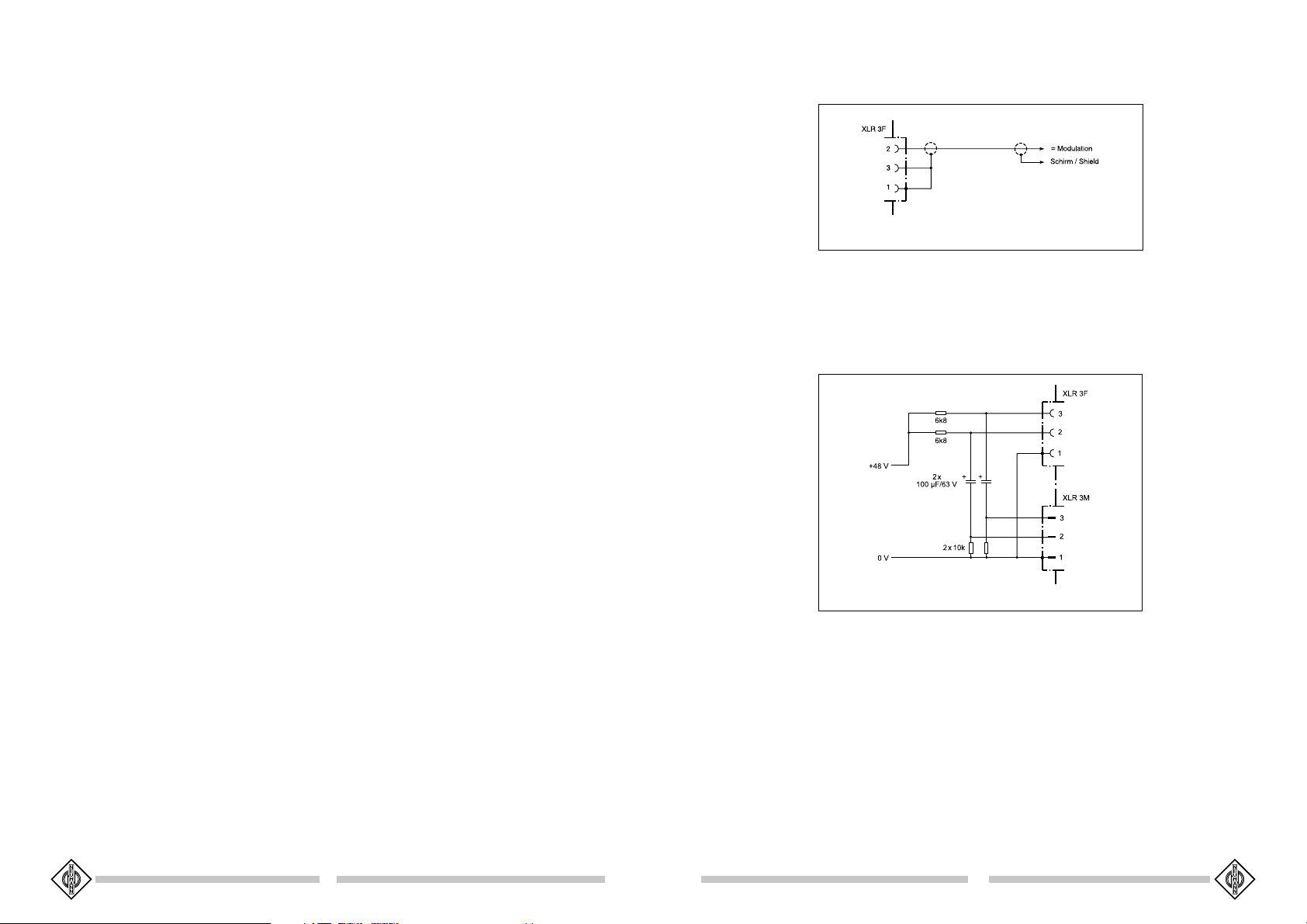
Bei den Mikrophonen ist jeweils Pin 2 normgerecht
die „heiße Phase“ und Pin 3 die „kalte Phase“. Daher muß beim Anschluß der Mikrophone bzw. der Speisegeräte an unsymmetrische Eingänge am Ausgang
des Speisegerätes Pin 3 an Masse (= Pin 1) gelegt
werden,während Pin 2 die Modulation trägt (siehe Abbildung 1). Die richtige Phasenlage relativ zu anderen
Studiomikrophonen ist damit auch bei unsymmetrischem Betrieb der Mikrophone gewährleistet.
N 48 i-2. It is designed to power two mono condenser microphones or one stereo microphone at 48 V
± 1 V, max. 2 x 5 mA. See Neumann bulletin No.
68832: “Phantom 48 Vdc Power Supplies“. Modulation polarity at the power supply units is identical
with that at the microphone.
The N 48 i-2 has 3-pin XLR-connectors and is available in the following versions:
NN
4848
i-2 (230i-2 (230
N
48
NN
4848
NN
4848
N
48
NN
4848
V)V)
i-2 (230
V) ............ blk .............................. Cat. No. 06500
i-2 (230i-2 (230
V)V)
i-2 (117i-2 (117
V)V)
i-2 (117
V) ............ blk .............................. Cat. No. 06502
i-2 (117i-2 (117
V)V)
2.3 Battery Operation
If a mains power source is not available, power can
be supplied by one of the following units
BSBS
48 i48 i
BS
48 i (for one microphone) ........................ Cat. No. 06494
BSBS
48 i48 i
BSBS
4848
ii
-2-2
BS
48
i
-2 (for two microphones) ................. Cat. No. 06496
BSBS
4848
ii
-2-2
Both units deliver 48 V ± 1 V, at 5 mA maximum
and are powered by a 9 V monobloc battery Type
IEC 6 F 22.
The BS 48 i-2 is equipped with 5-pin XLR-connectors, the BS 48 i with 3-pin XLR-connectors.
A „Series 180“ miniature microphone can be operated for at least 20 hours on a BS 48 i. See Neumann
bulletin No. 68832: “Phantom 48 Vdc Power Supplies”.
The assignment of the microphone terminals and the
polarity of the modulation leads is the same at the
output of the power supply units as it is at the microphone.
2.4 Operation with Unbalanced or Center
Tap Grounded Inputs
The 48 V phantom powering units BS 48 i, BS 48 i-2
and N 48 i-2 have dc-free outputs, so that no transformer is required for connection to an unbalanced
input.
In the microphones pin 2 is, conforming to standards,
the “hot phase“ and pin 3 is the “cold phase“.
Therefore, pin 3 must be connected to ground
(= pin 1), while pin 2 carries the modulation (see Figure 1). The correct phase position relative to other
studio microphones is thus ensured in balanced and
unbalanced mode of operation.
Bei vielen anderen als den o.g. Phantomspeisegeräten liegen nicht nur die Modulationsleitungen zum
Mikrophon auf dem
Potential der Speisespannung von +48 V,
sondern auch die
vom Speisegerät abgehenden Modulationsleitungen. Für die
in der Studiotechnik
allgemein üblichen
symmetrischen und
erdfreien Verstärker
und Mischpulteingänge ist dies ohne Bedeutung. Dagegen wird die
Speisespannung beim Anschluß an einseitig oder
mittengeerdete Verstärkereingänge kurzgeschlossen,
und es ist kein Betrieb möglich. Es bestehen folgende Lösungsmöglichkeiten:
a) In mittengeerdeten Geräten mit Eingangsübertrager (zum Beispiel einige NAGRA-Geräte) kann die
betreffende Erdverbindung fast immer
ohne Nachteile für
die Funktion des Gerätes aufgetrennt
werden.
b) In jede abgehende
Modulationsleitung
kann zur Abblockung
der 48 V-Gleichspannung eine RC-Kombination eingefügt
werden (siehe Abb. 2
und Neumann-Information Nr. 84221).
Abbildung 1 / Figure 1
Abbildung 2 / Figure 2
2.5 Kabel
Die akustischen Eigenschaften der Mikrophone werden auch durch sehr lange (Neumann-) Kabel nicht
beeinflußt. Erst bei Kabellängen deutlich über 300 m
macht sich ein Abfall im oberen Frequenzbereich bemerkbar.
Neumann bietet ein vielfältiges Kabelsortiment an,
von dem hier ein Ausschnitt erwähnt wird. Andere
als die genannten Kabellängen sowie Kabelmaterial
ohne Armaturen sind auf Wunsch lieferbar.
In the case of many other phantom powering units
(except those mentioned above), not only the mod-
ulation leads to the
microphone, but
also the outgoing
modulation leads
from the powering
unit are at the potential of the feed
voltage (+48 V). This
is of no significance
for the balanced,
floating amplifier and
mixing console inputs in general studio use. On the other hand, the
feed voltage will be short-circuited when connected
to single-ended or center tap grounded amplifier inputs, and no operation will be possible. This can be
circumvented as follows:
a) In center tap grounded equipment with input
transformer (e.g. some NAGRA units), the earth
lead can almost al-
ways be disconnect-
ed without affecting
the function of the
equipment.
b) In every out-
going modulation
lead, an RC net-
work can be incor-
porated to block the
48 Vdc voltage. (See
Figure 2 and Neu-
mann-Information
No. 84221).
2.5 Cables
The electroacoustic properties of the microphones
are not affected even by very long (Neumann) cables. However, if cables are well over 300 m, a falloff in the upper frequency range becomes apparent.
Neumann offers a wide range of cables. Only a selection is presented here. Other cable lengths or cable materials without connectors are available on request.
4
5
Page 4

IC 3 mtIC 3 mt
IC 3 mt ................................. sw .............................Best.-Nr. 06543
IC 3 mtIC 3 mt
10 m langes Mikrophonkabel, Durchmesser 5 mm, mit
Doppeldrallumspinnung als Abschirmung. Schwarzmatte 3-polige XLR-Steckverbinder.
ACAC
2020
AC
20 ...........................................................................Best.-Nr. 06595
ACAC
2020
Y-Kabel, 1 m lang, mit einer 5-poligen XLR-Buchse
und zwei 3-poligen XLR-Steckern, für die Verteilung
von 2-kanaliger Modulation auf 2 Monokanäle, z. B. bei
Verwendung des Speisegerätes BS 48 i-2.
ACAC
2121
AC
21 ........................................................................... Best.-Nr. 06597
ACAC
2121
Y-Kabel, 1 m lang, mit einem 5-poligen XLR-Stecker
und zwei 3-poligen XLR-Buchsen, für den Anschluß
zweier Monomikrophone an Speisegeräte mit 5-poligen Anschlußbuchsen, z. B. bei Verwendung des Speisegerätes BS 48 i-2.
ACAC
2222
AC
22 .......................................................................... Best.-Nr. 06598
ACAC
2222
0,3 m langes Adapterkabel mit einer 5-poligen XLRBuchse und einem 3,5 mm Stereoklinkenstecker, unsymmetrisch, für den Anschluß des 5-poligen XLRAusganges des Speisegerätes BS 48 i-2 oder der
Matrixbox MTX 191 A an Geräte mit 3,5 mm Stereoklinkenbuchse.
ACAC
2525
AC
25 .......................................................................... Best.-Nr. 06600
ACAC
2525
0,3 m langes Adapterkabel mit einer 3-poligen XLRBuchse und einem 6,3 mm Monoklinkenstecker, unsymmetrisch, für den Anschluß des 3-poligen XLRAusganges eines Speisegerätes BS 48 i oder
N 48 i-2 an Geräte mit 6,3 mm Monoklinkenbuchse.
ACAC
2727
AC
27 ........................................................................... Best.-Nr. 06602
ACAC
2727
Y-Kabel, 0,3 m lang, mit einer 5-poligen XLR-Buchse und zwei 6,3 mm Monoklinkensteckern, unsymmetrisch, für den Anschluß des 5-poligen XLR-Ausganges eines Speisegerätes BS 48 i-2 oder der
Matrixbox MTX 191 A an Geräte mit 6,3 mm Monoklinken-buchsen.
IC 3 mtIC 3 mt
IC 3 mt ................................. blk .............................. Cat. No. 06543
IC 3 mtIC 3 mt
10 m long microphone cable, 5 mm in diameter, with
double twist (double helix) braiding as shield. Threepin XLR connectors, matt black.
ACAC
2020
AC
20 ............................................................................ Cat. No. 06595
ACAC
2020
Y-cable, 1 m long, with one 5-pin XLR connector and
two 3-pin XLR connectors. It is used to split twochannel signals into two mono channels, when using,
for example, the BS 48 i-2 power supply.
ACAC
2121
AC
21 ........................................................................... Cat. No. 06597
ACAC
2121
Y-cable, 1 m long, with one 5-pin XLR connector and
two 3-pin XLR connectors. It is used to connect two
mono microphones to power supplies with 5-pin
connectors, when using, for example, the BS 48 i-2
power supply.
ACAC
2222
AC
22 ............................................................................ Cat. No. 06598
ACAC
2222
0.3 m adapter cable with a 5-pin XLR connector on
one end and an unbalanced 3.5 mm stereo jack on
the other end. It is used to connect the 5-pin XLR
output of the BS 48 i-2 power supply or the
MTX 191 A power amplifier to units with a 3.5 mm
stereo input.
ACAC
2525
AC
25 ........................................................................... Cat. No. 06600
ACAC
2525
0.3 m adapter cable with 3-pin XLR connector and
a 6.3 mm monojack, unbalanced. It is used to connect
3-pin XLR outputs of the BS 48 i or N 48 i-2 power
supplies to units with a 6.3 mm monojack input.
ACAC
2727
AC
27 ............................................................................ Cat. No. 06602
ACAC
2727
Y-cable, 0.3 m long, with a 5-pin XLR connector and
two 6.3 mm monojacks, unbalanced. It is used to
connect 5-pin XLR outputs of the BS 48 i-2 power
supply or the MTX 191 A matrix amplifier to units
with 6.3 mm monojack inputs.
3. Technische Daten
KM 183 / KM 184 / KM 185
Akust. Arbeitsweise .............. Druck-/Druckgradienten-
Richtcharakteristik .................... Kugel/Niere/Hyperniere
Übertragungsbereich.................................... 20 Hz...20 kHz
Feldübertragungsfaktor
1)
bei 1 kHz........................................ 12/15/10 mV/Pa ± 1 dB
Nennimpedanz .............................................................. 50 Ohm
Nennlastimpedanz ................................................ 1000 Ohm
Ersatzgeräuschpegel
CCIR 468-3 .............................................................24/22/24 dB
Ersatzgeräuschpegel
DIN/IEC 651 .................................................... 13/13/15 dB-A
Geräuschpegelabstand
CCIR 468-3 .............................................................70/72/70 dB
Geräuschpegelabstand
DIN/ IEC 651......................................................... 81/81/79 dB
Grenzschalldruckpegel für
0,5% Klirrfaktor 2)...................................... 140/138/142 dB
Max. Ausgangsspannung dabei ............................... 10 dBu
Phantomspeisespannung
(P48, DIN 45 596, IEC 1938) ....................... 48 V ± 4 V
Stromaufnahme ................................................................ 3,2 mA
Erforderlicher Steckverbinder ................................. XLR 3F
Gewicht ................................................................................ca. 80 g
Abmessungen .................................. Ø 22 mm x 107 mm
1)
bei 1 kHz an 1 kOhm Nennabschlußimpedanz. 1 Pa 94 dB SPL.
2)
Klirrfaktor des Mikrophonverstärkers bei einer Eingangsspannung, die der
von der Kapsel beim entsprechenden Schalldruck abgegebenen Spannung
entspricht.
empfänger
0 dB 20 µPa
3. Technical Specifications
KM 183 / KM 184 / KM 185
Acoustical op. principle .................... Pressure/Pressure-
Directional pattern .............. Omnidirectional/Cardioid/
Frequency range ..............................................20 Hz...20 kHz
Sensitivity at 1 kHz
1)
.............. 12/15/10 mV/Pa ± 1 dB
Rated impedance ........................................................ 50 ohms
Rated load impedance ....................................... 1000 ohms
Equivalent SPL
CCIR 468-3 .............................................................24/22/24 dB
Equivalent SPL
DIN/IEC 651 .................................................... 13/13/15 dB-A
S/N ratio
CCIR 468-3 .............................................................70/72/70 dB
S/N ratio
DIN/ IEC 651 ......................................................... 81/81/79 dB
Max. SPL for
0.5 % THD
2)
.............................................................. 140/138/142 dB
Max. output voltage ...................................................... 10 dBu
Phantom powering
(P48, DIN 45 596, IEC 1938) ....................... 48 V ± 4 V
Current consumption .................................................. 3.2 mA
Matching connector ....................................................... XLR 3F
Weight ........................................................................approx. 80 g
Dimensions......................................... Ø 22 mm x 107 mm
1)
at 1kHz into 1 kohm minimum terminating impedance, 1 Pa 94 dB SPL.
2)
THD of the microphone amplifier at an input voltage equivalent to the
capsule output at the specified SPL.
gradient transducer
Hypercardioid
0 dB 20 µPa
6
7
Page 5

4. Frequenzgänge und Polardiagramme
Frequency Responses and Polar Patterns
KM 183KM 183
KM 183
KM 183KM 183
°
°
KM 183KM 183
KM 183
KM 183KM 183
°
KM 184KM 184
KM 184
KM 184KM 184
KM 185KM 185
KM 185
KM 185KM 185
KM 184KM 184
KM 184
KM 184KM 184
KM 185KM 185
KM 185
KM 185KM 185
8
9
Page 6

5. Zubehör
Sämtliche Zubehörteile haben eine schwarzmatte
Oberfläche. Weitere Artikel sind im Katalog „Zubehör“ beschrieben.
5.1 Stativgelenke
SG 21/17 mtSG 21/17 mt
SG 21/17 mt ................... sw ............................. Best.-Nr. 06149
SG 21/17 mtSG 21/17 mt
(gehört zum Lieferumfang)
Das Stativgelenk SG 21/17 mt besitzt eine Kunststoffklammer zur Aufnahme von Kleinmikrophonen.
Es hat einen Gewindeanschluß 5/8"-27-Gang mit Reduzierstück für 1/2"- und 3/8"-Gewindezapfen. Eine
weitere Kunststoffklammer mit 17 mm Durchmesser
wird mitgeliefert. Damit kann das Mikrophon am
Steckverbinder gehalten werden.
DS 21 mtDS 21 mt
DS 21 mt .......................... sw ............................. Best.-Nr. 06798
DS 21 mtDS 21 mt
Das Doppelstativ DS 21 mt wurde für den Fall konstruiert, daß zwei Kleinmikrophone an einem Ort
benötigt werden, und gestattet, diese einfach und
übersichtlich anzuordnen.
Es läßt sich auf Tisch- und Fußbodenständern ebenso
wie an Galgen montieren. Damit steht auch für alle
die Anwendungen, bei denen zum Beispiel aus
Gründen der Funktionssicherheit grundsätzlich ein
zweites Mikrophon am gleichen Ort einsatzbereit
sein muß, ein vorzügliches Hilfsmittel zur Verfügung.
Das DS 21 mt hat einen Gewindeanschluß 5/8"-27Gang. Ein Reduzierstück zur Verbindung mit 1/2"und 3/8"-Gewindezapfen wird mitgeliefert.
DSDS
110110
DS
110 .................................. sw .............................Best.-Nr. 07342
DSDS
110110
Das DS 110 enthält zwei Schienen zur Aufnahme
zweier Kleinmikrophone. Sie können auf unterschiedliche Weise montiert werden und erlauben unterschiedliche Anordnungen:
1. die parallele Montierung,
2. die ORTF-Montierung, die einen Winkel von 110°
bei 170 mm Abstand einschließen,
3. die Montierung für (XY-)Intensitätsstereophonie.
Die Mikrophonkapseln sind hierbei unmittelbar übereinander angeordnet.
Ein Schwinggummi dient zur Körperschallunterdrükkung. Der Gewindeanschluß hat 5/8"-27-Gang. Ein
Adapter zur Verbindung mit 1/2"- und 3/8"-Gewindezapfen wird mitgeliefert.
5. Accessories
All accessories have a matt black finish. Further articles are described in the catalog “Accessories”.
5.1 Swivel Mount
SG 21/17 mtSG 21/17 mt
SG 21/17 mt ................... blk ..............................Cat. No. 06149
SG 21/17 mtSG 21/17 mt
(included in the supply schedule)
The SG 21/17 mt stand mount has a plastic clamp
for miniature microphones. It has a 5/8"-27 thread
with an adapter for 1/2" and 3/8" studs. An additional
clamp, 17 mm in diameter, is included. It may be
exchanged when the microphone should be held
more elegantly at the XLR-connector.
DS 21 mtDS 21 mt
DS 21 mt .......................... blk .............................. Cat. No. 06798
DS 21 mtDS 21 mt
Dual microphone mount for use in situations where
two Neumann microphones are required, e.g. in
broadcasting applications.
It can be mounted equally easily on a table or floor
stand or on a boom. This is a real advantage in all
situations where, for instance, a second microphone
must be ready for use at all times at a particular location. The DS 21 has a 5/8"-27 thread. A reducer
for 1/2" and 3/8" studs is also provided.
DSDS
110110
DS
110 .................................. blk.............................. Cat. No. 07342
DSDS
110110
The DS 110 is equipped with two brackets to hold
two miniature microphones. Both can be mounted in
various ways allowing three different angular arrangements.
1. Parallel mounting.
2. In ORTF mounting the microphones are at an angle of 110° and the microphone capsules are spaced
170 mm apart from each other.
3. When mounted for (XY-)intensity stereophony,
the capsules are positioned right above each other
(coincident).
An anti-vibration mount suppresses structure-borne
noise. The DS 110 has a 5/8"-27 female thread. A
threaded adapter for the connection to 1/2" and 3/8"
studs is included.
DSDS
120120
DS
120 .................................. sw .............................Best.-Nr. 07343
DSDS
120120
Das DS 120 hat eine 150 mm lange Schiene, die
zwei verschiebbare 1/2"-Gewindeschrauben zur Befestigung zweier Mikrophone in ihren Halterungen
enthält. Hierbei sind Abstand und Winkel für die
Anordnung der Mikrophone wählbar. Der Gewindeanschluß hat 5/8"-27-Gang. Ein Reduzierstück zur
Verbindung mit 1/2"- und 3/8"-Gewindezapfen wird
mitgeliefert.
MKVMKV
MKV ........................................ sw ............................. Best.-Nr. 07199
MKVMKV
Die Mikrophonklammer MKV ist eine Schnellspannklammer aus Kunststoff für Mikrophone mit Schaftdurchmessern von 17 mm bis 30 mm. Die Klammer
ist schwenkbar und hat einen Gewindeanschluß 5/8"27-Gang. Ein Reduzierstück zur Verbindung mit 1/2"und 3/8"-Gewindezapfen wird mitgeliefert.
5.2 Tisch- und Fußbodenständer
MF 2MF 2
MF 2 ..................................... sw ............................. Best.-Nr. 07266
MF 2MF 2
Der Mikrophonfuß MF 2 ist ein kleiner Tischständer
mit Messingfuß, Durchmesser 60 mm, 340 g schwer,
sehr standsicher. Der Ständer ist schwarzmatt lackiert
und steht gleitfest auf einer Moosgummischeibe.
Der 1/2"-Gewindezapfen zur Aufnahme z.B. des Stativgelenkes SG 21/17 mt ist zur Körperschallunterdrückung durch ein Gummielement vom Fuß entkoppelt.
MF 3MF 3
MF 3 ........................................ sw ............................. Best.-Nr. 07321
MF 3MF 3
Der Mikrophonfuß MF 3 ist ein Tischständer mit Eisenfuß, 1,6 kg schwer, Durchmesser 110 mm. Der
Ständer ist schwarzmatt lackiert und steht gleitfest
auf einer Moosgummischeibe. Ein umwendbarer Gewindezapfen und ein mitgeliefertes Reduzierstück ermöglichen die Verwendung für 1/2"- und 3/8"-Gewindeanschlüsse.
MF 4MF 4
MF 4 ........................................ sw ............................. Best.-Nr. 07337
MF 4MF 4
Der Mikrophonfuß MF 4 ist ein Fußbodenständer aus
Grauguß, ca. 2,6 kg schwer, Durchmesser 160 mm. Der
Ständer ist schwarzmatt lackiert und steht gleitfest auf
einem Gummiring. Ein umwendbarer Gewindezapfen
und ein mitgeliefertes Reduzierstück ermöglichen die
Verwendung für 1/2"- und 3/8"- Gewindeanschlüsse.
5.3 Stativverlängerungen
Die Stativverlängerungen STV.. werden zwischen Fußbodenständer (z.B. MF 3, MF 4) und Stativgelenke
(z.B. SG 21/17 mt) geschraubt. Dadurch entstehen
unterschiedlich hohe Tisch- oder Fußbodenstative.
DSDS
120120
DS
120 .................................. blk.............................. Cat. No. 07343
DSDS
120120
The DS 120 has a 150 mm long support bar with
two movable 1/2" threaded studs. Two microphones
in their mounts can be attached. The spacing and angle
between the microphones are freely. It has a 5/8"27 female thread. A threaded adapter for the connection to 1/2" and 3/8" studs is included.
MKVMKV
MKV ..................................... blk .............................. Cat. No. 07199
MKVMKV
Quick-release plastic clamp for microphones with
body diameters from 17 to 30 mm. The clamp can
be swivelled and has a 5/8"-27 thread. A reducer for
1/2" and 3/8" studs is also provided.
5. 2 Table and Floor Stands
MF 2MF 2
MF 2 ........................................ blk .............................. Cat. No. 07266
MF 2MF 2
Small table stand with brass base, 60 mm in diameter, 340 g, very stable. The stand has a matt black
finish and rests on a nonskid rubber disk. The 1/2"
stud for e.g. the SG 21/17 mt stand mount is isolated against structure borne vibrations by means of
a rubber shock mount.
MF 3MF 3
MF 3 ........................................ blk .............................. Cat. No. 07321
MF 3MF 3
Table stand with iron base, 1.6 kg, 110 mm in diameter. The table stand has a matt black finish and
rests on a nonskid rubber disk attached to the bottom. A reversible stud and a reducer for 1/2" and
3/8" threads are also supplied.
MF 4MF 4
MF 4 ........................................ blk .............................. Cat. No. 07337
MF 4MF 4
Floor stand with grey cast iron base, 2.6 kg, 160 mm
in diameter. The floor stand has a matt black finish
and rests on a nonskid rubber disk attached to the
bottom. A reversible stud and a reducer for 1/2" and
3/8" threads are also supplied.
5.3 Stand Extensions
The STV ... stand extensions are screwed between
floor stands (e.g. MF 3, MF 4) and swivel mount (e.g.
SG 21/17 mt) to provide table or floor stands of variable heights.
10
11
Page 7

Die STV ... haben eine Länge von 40, 200, 400 oder
600 mm. Durchmesser: 19 mm.
STVSTV
44
STV
4 ...................................... sw ............................. Best.-Nr. 06190
STVSTV
44
STVSTV
2020
STV
20 ................................... sw .............................Best.-Nr. 06187
STVSTV
2020
STVSTV
4040
STV
40 ................................... sw .............................Best.-Nr. 06188
STVSTV
4040
STVSTV
6060
STV
60 ................................... sw .............................Best.-Nr. 06189
STVSTV
6060
5.4 Schwanenhälse
SMK 8 iSMK 8 i
SMK 8 i ................................ sw .............................Best.-Nr. 06181
SMK 8 iSMK 8 i
Der Schwanenhals SMK 8 i hat eine Länge von
360 mm und dient zum elektrischen und mechanischen Anschluß eines Mikrophons mit 3-poligem
XLR-Stecker. Eine Kontermutter arretiert das Mikrophon klapperfrei und bietet einen gewissen Diebstahlschutz. Der Kabelaustritt ist seitlich über dem Gewindeanschluß. Kabellänge 4,5 m, Kabelstecker A3M.
Gewindeanschluß: 5/8"-27-Gang zur Befestigung des
Schwanenhalses. Ein mitgeliefertes Reduzierstück ermöglicht die Befestigung auch auf 1/2"- und 3/8"-Gewindezapfen.
5.5 Abhängevorrichtung
MNV 21 mtMNV 21 mt
MNV 21 mt ....................... sw ............................. Best.-Nr. 06802
MNV 21 mtMNV 21 mt
Die Mikrophonneigevorrichtung MNV 21 mt besteht
aus einer schwenkbaren Mikrophonklammer zur Aufnahme eines Neumann-Kleinmikrophons und aus einer Kabelführung mit Drehverschluß.
Die MNV 21 mt ermöglicht die Einstellung der Mikrophonneigung bei frei am Kabel hängendem Mikrophon.
The STVs are 40, 200, 400 or 600 mm long.
Diameter: 19 mm.
STVSTV
44
STV
4 ...................................... blk .............................. Cat. No. 06190
STVSTV
44
STVSTV
2020
STV
20 ................................... blk .............................. Cat. No. 06187
STVSTV
2020
STVSTV
4040
STV
40 ................................... blk .............................. Cat. No. 06188
STVSTV
4040
STVSTV
6060
STV
60 ................................... blk .............................. Cat. No. 06189
STVSTV
6060
5.4 Goosenecks
SMK 8 iSMK 8 i
SMK 8 i ................................ blk .............................. Cat. No. 06181
SMK 8 iSMK 8 i
The SMK 8 i gooseneck is 360 mm long, and is used
for the mechanical and electrical connection of a microphone with 3-pin XLR connector. A locknut secures the microphone firmly and acts as a safeguard
against theft. Cable outlet at the side via thread connector. Cable length 4.5 m, cable plug A3M.
Thread connector: 5/8"-27 thread for securing the
gooseneck. A reducer is for 1/2" and 3/8" studs is also
included.
5.5 Auditorium Hanger and Suspensions
MNV 21 mtMNV 21 mt
MNV 21 mt ....................... blk ..............................Cat. No. 06802
MNV 21 mtMNV 21 mt
The MNV 21 mt auditorium hanger for Neumann
miniature microphones comprises a tilting microphone clamp and a cable guide with ring fastener.
The MNV 21 mt allows the microphone tilt to be
adjusted with the microphone freely suspended from
its own cable.
lyurethanschaum lieferbar. Diese Windschirme erzeugen keine störenden Resonanzen und beeinflussen
nicht die Richtcharakteristik des Mikrophons. Das
Übertragungsmaß wird im oberen Frequenzbereich
geringfügig gedämpft.
Zwei Ausführungsarten stehen zur Verfügung:
WNS 100WNS 100
WNS 100 ............................ sw ............................. Best.-Nr. 07323
WNS 100WNS 100
(gehört zum Lieferumfang)
.................................................... rt ................................ Best.-Nr. 07324
.................................................... gn .............................. Best.-Nr. 07325
.................................................... ge .............................. Best.-Nr. 07326
.................................................... bl ...............................Best.-Nr. 07327
.................................................... ws ............................. Best.-Nr. 07328
Wind- und Nahbesprechungsschutz: Durchmesser
ca. 45 mm. Dämpfung des Windgeräusches ca. 18 dB.
Dämpfung bei 15 kHz ca. 2 dB*. Lieferbar in den Farben schwarz, rot, grün, gelb, blau und weiß.
WNS 110WNS 110
WNS 110 ............................ sw ............................. Best.-Nr. 08535
WNS 110WNS 110
Akustisch transparenter Wind- und Nahbesprechungsschutz mit erhöhter Effizienz. Durchmesser
45 mm, Länge 70 mm.
WS 100WS 100
WS 100 ................................ sw ............................. Best.-Nr. 06751
WS 100WS 100
Durchmesser ca. 90 mm. Dämpfung des Windgeräusches ca. 23 dB. Dämpfung bei 15 kHz ca. 4 dB*.
Farbe schwarz.
* Die Dämpfung des Windgeräusches wurde ohne
elektrisches Filter gemessen, in verwirbelter Luftströmung der Geschwindigkeit 20 km/h, erzeugt von einer geräuschlos arbeitenden Windmaschine.
affect the microphone’s directional characteristic. The
frequency response is only slightly attenuated in the
higher frequency range.
The windscreens are available as follows:
WNS 100WNS 100
WNS 100 ............................ blk .............................. Cat. No. 07323
WNS 100WNS 100
(included in the supply schedule)
.................................................... red .............................Cat. No. 07324
.................................................... green ........................ Cat. No. 07325
.................................................... yellow ...................... Cat. No. 07326
.................................................... blue........................... Cat. No. 07327
.................................................... white ........................ Cat. No. 07328
Wind and pop protection/screen: diameter approx.
45 mm. Wind noise suppression approx. 18 dB. Attenuation at 15 kHz approx. 2 dB*.
WNS 110WNS 110
WNS 110 ............................ blk .............................. Cat. No. 08535
WNS 110WNS 110
Acoustic transparent wind and pop protection/screen
with improved efficiency. Diameter 45 mm, length
70 mm.
WS 100WS 100
WS 100 ................................ blk .............................. Cat. No. 06751
WS 100WS 100
Diameter approx. 90 mm, black. Wind noise suppression approx. 23 dB. Attenuation at 15 kHz approx. 4 dB*.
* Values measured in pulsating air currents produced
by a noiseless wind machine at 20 km/h (without
electrical filter).
5. 6 Elastische Aufhängung
Um mechanische Erschütterung fernzuhalten, empfiehlt sich die Verwendung einer elastischen Mikrophonaufhängung.
EA 2124 A mtEA 2124 A mt
EA 2124 A mt ................ sw ............................. Best.-Nr. 08433
EA 2124 A mtEA 2124 A mt
Die Elastische Aufhängung EA 2124 A mt besitzt einen schwenkbaren Gewindeanschluß 5/8"-27-Gang
mit einem Reduzierstück zur Verbindung mit 1/2"und 3/8"-Gewindezapfen. Die Oberfläche ist schwarzmatt.
5.7 Windschirme
Zum Vermeiden von Störgeräuschen, die bei Nahbesprechung, Windeinfluß oder z.B. bei schnellem
Schwenken des Mikrophongalgens auftreten können,
sind Windschutzeinrichtungen aus offenporigem Po-
5. 6 Elastic Suspension
Elastic suspension is recommended to prevent the
microphone from being exposed to strong mechanical vibrations caused by structure borne shock waves.
EA 2124 A mtEA 2124 A mt
EA 2124 A mt ................ blk .............................. Cat. No. 08433
EA 2124 A mtEA 2124 A mt
The EA 2124 A mt has a tilting 5/8"-27 female
thread. A reducer for 1/2" and 3/8" studs is included. Matt black finish.
5.7 Windshields
To protect against noise caused by wind, close talking, and rapid movement on a boom, opencell polyurethane foam windshields are available. These windshields have no disturbing resonances and do not
12
5. 8 Popschutz
PS 15PS 15
PS 15 ...................................... sw ............................. Best.-Nr. 08472
PS 15PS 15
Der Popschirm PS 10 bietet einen sehr wirksamen
Schutz vor den sogenannten Popgeräuschen. Er besteht
aus einem runden dünnen Holzrahmen, der beidseitig
mit schwarzer Gaze bespannt ist.
Der um ca. 230° schwenkbare Stativanschlußstutzen
hat 5/8"-27-Gang-Innengewinde mit einem Reduzierstück
zur Verbindung mit 1/2"- und 3/8"-Gewindezapfen.
Zum Lieferumfang gehört ein zweiseitig konterbarer
Gewindezapfen, um den Popschirm z.B. an die Klammer MKV zu schrauben. Damit kann er an die Stativstangen oder an die Steckverbinder geklammert werden.
5.8 Popscreen
PS 15PS 15
PS 15 ...................................... blk .............................. Cat. No. 08472
PS 15PS 15
The PS 10 popshield provides excellent suppression
of so-called pop noise. It consists of a round, thin
wooden frame covered with black gauze on both
sides.
The stand adaptor with 5/8"-27 female thread can be
altered by 230°. A reducer for connection to 1/2"
and 3/8" studs is included.
For mounting the popshield to the MKV quick-release
clamp, a double-sided stud with locknut is included
in the supply schedule. Used in conjunction with the
MKV quick-release clamp the popshield can be attached to stands or connectors.
13
Page 8

N 48 i-2
BS 48 i
BS 48 i-2
MKV
MF 2 MF 3
AC 20
AC 25
DS 21 mt PS 15
AC 21 AC 22
AC 27
DS 110 DS 120
MF 4
EA 2124 A mt
WS 100
SMK 8 i
WNS 100SG 21/17 mt
MNV 21 mt
WNS 110
14
15
Page 9

Irrtümer und technische Änderungen vorbehalten • Errors excepted, subject to changes
Printed in Germany • Publ. 04/04 76833
/ A 04
 Loading...