

Page 1

ProSafe Premium 3 x 3 Dual-Band Wireless-N Access Point WNDAP620
Reference Manual
350 East Plumeria Drive
San Jose, CA 95134
USA
October 2012
202-10983-02
v2.0
Page 2

ProSafe Premium 3 x 3 Dual-Band Wireless-N Access Point WNDAP620
Support
Thank you for choosing NETGEAR.
After installing your device, locate the serial number on the label of your product and use it to register your product
at https://my.netgear.com. You must register your product before you can
NETGEAR recommends registering your product through the NETGEAR
support, visit http://support.netgear.com.
Phone (US & Canada only): 1-888-NETGEAR.
Phone (Other Countries): Check the li
http://support.netgear.com/gen
NETGEAR recommends that you use only the official NETGEAR support resources.
st of phone numbers at
eral/contact/default.aspx.
use NETGEAR telephone support.
website. For product updates and web
Trademarks
NETGEAR, the NETGEAR logo, and Connect with Innovation are trademarks and/or registered trademarks of
NETGEAR, Inc. and/or its subsidiaries in the United States and/or other countries. Information is subject to change
without notice. Other brand and product names are registered trademarks or trademarks of their respective
holders. NETGEAR, Inc. All rights reserved.
Revision History
Publication
Part Number
202-10983-02 2.0 October 2012 Minor nontechnical revisions
202-10983-02 1.0 September 2012 • Added and refined information (no new features added)
202-10983-01 1.0 August 2012 First publication
Version Publish Date Comments
• Added Appendix B, Command-Line R eference
• Added Index
2
Page 3

Contents
Chapter 1 Introduction
Chapter 2 Installation and Basic Configuration
About the ProSafe Premium 3 x 3 Dual-Band Wireless-N Access Point
WNDAP620 . . . . . . . . . . . . . . . . . . . . . . . . . . . . . . . . . . . . . . . . . . . . . . . . .6
What Is in the Box? . . . . . . . . . . . . . . . . . . . . . . . . . . . . . . . . . . . . . . . . . . .7
System Requirements . . . . . . . .
Key Features and Standards . . . . . . . . . . . . . . . . . . . . . . . . . . . . . . . . . . . .8
Supported Standards and Conventions . . . . . . . . . . . . . . . . . . . . . . . . . .8
Key Features . . . . . . . . . . . . . . . . . . . . . . . . . . . . . . . . . . . . . . . . . . . . . .9
802.11b/g/n and 802.11a/n Standards–Based W
Autosensing Ethernet Connections with Auto Uplink
Hardware Description. . . . . . . . . . . . . . . . . . . . . . . . . . . . . . . . . . . . . . . . .11
Top Panel. . . . . . . . . . . . . . . . . . . . . . . . . . . . . . . . . . . . . . . . . . . . . . . .11
Rear Panel . . . . . . . . . . . . . . . . . . . . . . . . . . . . . . . . . . . . . . . . . . . . . . .13
Bottom Panel with Product Label . . . . . . . . . . . . . . . . . . . . . . . . . . . . . .13
Register the Wireless Access Point . . . . . . . . .
. . . . . . . . . . . . . . . . . . . . . . . . . . . . . . . . .8
ireless Networking . . .11
. . . . . . . . . . . . . . .11
. . . . . . . . . . . . . . . . . . . . .14
What You Need Before You Begin. . . . . . . . . . . . . . . . . . . . . . . . . . . . . . .17
Wireless Equipment Placement and Range G
Ethernet Cabling Requirements . . . . . . . . . . . . . . . . . . . . . . . . . . . . . . .18
LAN Configuration Requirements. . . . . . . . . . . . . . . . . . . . . . . . . . . . . .18
Hardware Requirements for Computers on Your LAN
Operating Frequency (Channel) Guidelines. . .
Requirements for Entering IP Addresses . . . . . . . . . . . . . . . . . . . . . . . .19
Install and Configure the Wireless Access Point . . . . . . . . . . . . . . . . . . . .20
Connect the Wireless Access Point to a Computer
Log In to the Wireless Access Point
Configure Basic General System Settings
Configure the IPv4 Settings . . .
Configure the Optional DHCPv4 Server
Configure the Basic Wireless Settings
Test Basic Wireless Connectivity . . . . . . . . . . . . . . . . . . . . . . . . . . . . . . . .34
Mount the Wireless Access Point. . . . . . . . .
Ceiling Installation . . . . . . . . . . . . . . . . . . . . . . . . . . . . . . . . . . . . . . . . .35
Wall Installation . . . . . . . . . . . . . . . . . . . . . . . . . . . . . . . . . . . . . . . . . . .38
Desk Installation . . . . . . . . . . . . . . . . . . . . . . . . . . . . . . . . . . . . . . . . . . .41
. . . . . . . . . . . . . . . . . . . . . . . . . . . .22
. . . . . . . . . . . . . . . . . . . . . . . . . . . . . . .25
. . . . . . . . . . . . . . . . . . . . . . . . . .28
uidelines. . . . . . . . . . . . .17
. . . . . . . . . . . . . .19
. . . . . . . . . . . . . . . . . . .19
. . . . . . . . . . . . . . . .20
and Time Settings . . . . . . . .23
. . . . . . . . . . . . . . . . . . . . . . . . .27
. . . . . . . . . . . . . . . . . . . . . . .35
3
Page 4

ProSafe Premium 3 x 3 Dual-Band Wireless-N Access Point WNDAP620
Chapter 3 Wireless Configuration and Security
Wireless Data Security Options . . . . . . . . . . . . . . . . . . . . . . . . . . . . . . . . .42
Security Profiles . . . . . . . . . . . . . . . . . . . . . . . . . . . . . . . . . . . . . . . . . . . . .44
Before You Change the SSID, WEP, and WPA Settings . . . . . . . . . . . .46
Configure and Enable Security Profiles . . . . . . . . . . . . . . . . . . . . . . . . . 48
Configure RADIUS Server Settings . . . . . . . . . . . . . . . . . . . . . . . . . . . . . . 57
Restrict Wireless Access by MAC Address . . . . . . . . . . . . . . . . . . . . . . . .60
Schedule the Wireless Radio to Be Turned Off . . . . . . . . . . . . . . . . . . . . . 61
Configure Basic Wireless Quality of Service . . . . . . . . . . . . . . . . . . . . . . .62
Chapter 4 Management and Monitoring
Enable Remote Management. . . . . . . . . . . . . . . . . . . . . . . . . . . . . . . . . . . 64
SNMP Management. . . . . . . . . . . . . . . . . . . . . . . . . . . . . . . . . . . . . . . .64
Secure Shell and Telnet Management. . . . . . . . . . . . . . . . . . . . . . . . . .66
Upgrade the Wireless Access Point
Web Browser Upgrade Procedure . . . . . . . . . . . . . . . . . . . . . . . . . . . . .68
TFTP Server Upgrade Procedure. . . . . . . . . . . . . . . . . . . . . . . . . . . . . .69
Manage the Configuration File or Reset to Factory
Save the Configuration. . . . . . . . . . . . . . . . . . . . . . . . . . . . . . . . . . . . . .70
Restore the Configuration. . . . . . . . . . . . . . . . . . . . . . . . . . . . . . . . . . . . 71
Restore the Wireless Access Point to the
Reboot the Wireless Access Point without Restoring
Default Configuration . . . . . . . . . . . . . . . . . . . . . . . . . . . . . . . . . . . . . . .73
Change the Administrator Password . . . . . . . . . . . . . . . . . . . . . . . . . . . . .74
Manage User Accounts . . . . . . . . . . . . . . . . . . . . . . . . . . . . . . . . . . . . . . .75
Enable the Syslog Server. . . . . . . . . . . . . . . . . . . . . . . . . . . . . . . . . . . . . . 76
Monitor the Wireless Access Point. . . . . . . . . . . . . . . . . . . . . . . . . . . . . . .77
View System Information . . . . . . . . . . . . . . . . . . . . . . . . . . . . . . . . . . . . 77
Monitor Wireless Stations. . . . . . . . . . . . . . . . . . . . . . . . . . . . . . . . . . . .80
View the Activity Log . . . . . . . . . . . . . . . . . . . . . . . . . . . . . . . . . . . . . . . 83
Traffic Statistics . . . . . . . . . . . . . . . . . . . . . . . . . . . . . . . . . . . . . . . . . . .83
Enable Rogue AP Detection and Monitor Access
Enable and Configure Rogue AP Detection. . .
View and Save Access Point Lists . . . . . . . . . . . . . . . . . . . . . . . . . . . . .87
Configure Wireless Intrusion Detection and Prev
Configure Wireless Intrusion Detection and Prevention Policy Settings 89
Configure Wireless Intrusion Detection and Prevention Mail Settings . . 95
Monitor Traps, Counters, and Ad Hoc Networks . . . . . . . . . . . . . . . . . .96
Software . . . . . . . . . . . . . . . . . . . . . .67
Defaults . . . . . . . . . . . 70
Factory Default Settings. . . .71
the
Points. . . . . . . . . . . . . .85
. . . . . . . . . . . . . . . . . . . 85
ention. . . . . . . . . . . . . . . 89
Chapter 5 Advanced Configuration
Configure IPv6 Settings and Optional DHCPv6 Server Settings . . . . . . . . 99
Configure the IPv6 Settings . . . . . . . . . . . . . . . . . . . . . . . . . . . . . . . . . .99
Configure the Optional DHCPv6 Server
Configure Spanning Tree Protocol, 802.1Q VLAN, and
Link Layer Discovery Protocol . . . . . . . . . . . . . . . . . . . . . . . . . . . . . . . . .103
Configure STP and VLANs. . . . . . . . . . . . . . . . . . . . . . . . . . . . . . . . . .103
4
. . . . . . . . . . . . . . . . . . . . . . . .101
Page 5

ProSafe Premium 3 x 3 Dual-Band Wireless-N Access Point WNDAP620
Configure Ethernet LLDP . . . . . . . . . . . . . . . . . . . . . . . . . . . . . . . . . . .105
Configure Hotspot Settings. . . . . . . . . . . . . . . . . . . . . . . . . . . . . . . . . . . .106
Configure Advanced Wireless Settings . . . . . .
Configure Advanced Quality of Service Settings
Configure Quality of Service Policies . . . . . . . . . . . . . . . . . . . . . . . . . . . .112
Configure Wireless Bridging. . . . . . . . . . . . . . . . . . . . . . . . . . . . . . . . . . .118
Configure a Point-to-Point Wireless Network . . . . . . . . . . . . . . . . . . . .118
Configure a Point-to-Multipoint Wireless Net
Configure the Wireless Access Point to Repeat the Wireless
Signal Using Point-to-Multipoint Bridge Mode
. . . . . . . . . . . . . . . . . . . .107
. . . . . . . . . . . . . . . . . . .110
work . . . . . . . . . . . . . . . .122
. . . . . . . . . . . . . . . . . . .126
Chapter 6 Troubleshooting
Basic Functioning. . . . . . . . . . . . . . . . . . . . . . . . . . . . . . . . . . . . . . . . . . .132
Verify the Correct Sequence of Events at Startup . . . . . . . . . . . . . . . .132
No LEDs Are Lit on the Wireless Access Point . . . . . . . . . . . . . . . . . .132
The Active LED or the LAN LED Is Not Lit . . . . . . . . . . . . . . . . . . . . . .133
The WLAN LED Does Not Light Up . . . . . . . . . . . . . . . . . . . . . . . . . . .133
You Cannot Access the Internet or the LAN from a
Wireless-Capable Computer . . . . . . . . . . . .
You Cannot Configure the Wireless Access Point from a Browser . . . . .134
When You Enter a URL or IP Address a Time-Out Error Occurs. . . . . . .135
Troubleshoot a TCP/IP Network Using the Ping Utility. . . . . . . . . . . . . . .135
Test the LAN Path to Your W
Test the Path from Your C
Problems with Date and Time . . . . . . . . . . . . . . . . . . . . . . . . . . . . . . . . .137
Use the Packet Capture Tool . . . . . . . . . . . . . . . . . . . . . . . . . . . . . . . . . .138
ireless Access Point. . . . . . . . . . . . . . . .136
omputer to a Remote Device . . . . . . . . . . .137
. . . . . . . . . . . . . . . . . . . . . .134
Appendix A Supplemental Information
Technical Specifications. . . . . . . . . . . . . . . . . . . . . . . . . . . . . . . . . . . . . .139
Factory Default Settings . . . . . . . . . . . . . . . . . . . . . . . . . . . . . . . . . . . . . .142
Appendix B Command-Line Reference
Appendix C Notification of Compliance
Index
5
Page 6

1. Introduction
This chapter introduces the NETGEAR® ProSafe® Premium 3 x 3 Dual-Band Wireless-N
Access Point WNDAP620 and describes some of the key features. The chapter includes the
following sections:
• About the ProSafe Premium 3 x 3 Dual-Band Wireless-N Access Point WNDAP620
• What Is in the Box?
• System Requirements
• Key Features and Standards
• Hardware Description
• Register the Wireless Access Point
Note: For more information about the topics covered in this manual, visit
the Support website at http://support.netgear.com.
1
Note: Firmware updates with new features and bug fixes are made
available from time to time at
products can regularly check the site a
or you can check for and download new firmware manually. If the
features or behavior of your product do not match what is described
in this guide, you might need to update your firmware.
downloadcenter.netgear.com. Some
nd download new firmware,
About the ProSafe Premium 3 x 3 Dual-Band Wireless-N Access Point WNDAP620
The ProSafe Premium 3 x 3 Dual-Band Wireless-N Access Point WNDAP620, going forward
in this manual referred to as the wireless access point, is a powerful building block of a
wireless LAN infrastructure. It provides either 2.4 GHz 802.11b/g/n or 5 GHz 802.11a/n
conn
ectivity between wired Ethernet networks and radio-equipped wireless notebook
systems, desktop systems, print servers, and other devices. Support for three transmit radio
6
Page 7

ProSafe Premium 3 x 3 Dual-Band Wireless-N Access Point WNDAP620
chains and three receive radio chains, also referred to as 3x3 multiple input, multiple output
(MIMO), can increase wireless throughput considerably.
The wireless access point provides wireless connectivi ty to multiple wireless network devices
within
(NIC) through an antenna. Typ ically , an individual in-building wireless access point p rovides a
maximum connectivity area with about a 500-foot radius. The wireless access point can
support a maximum of 128 clients in a range of several hundred feet. The throughput is
shared
points to meet the required coverage, throughput, and quality of your wireless network.
a fixed range or area of coverage—interacting with a wireless network interface card
between all clients. Make sure that you install a sufficient number of wireless access
The wireless access point acts as a bridge b
Connecting multiple wireless access points through a wired Ethernet backbone can further
increase the wireless network coverage. As a mobile computing device moves out of the
range of one wireless access point, it moves into the range of another. As a result, wireless
clients can freely roam from one wireless access point to another and still maintain a
seamless connection to the network.
The autosensing capability of the wireless access point allows packet transmission at up to
50 Mbps, or at reduced speeds to compensate for dist ance or electromagnetic interference.
4
Advanced wireless features that are supported on the wireless access point include a
wireless intrusion d
configurable wireless QoS policies.
You can manage the wireless access point from either an IPv4 or IPv6 address, and the
wireless access
etection system (IDS), wireless intrusion prevention system (IPS), and
point can allocate either IPv4 or IPv6 DHCP addresses to its wireless clients.
etween the wired LAN and wireless clients.
What Is in the Box?
The product package contains the following items:
• Pro
• Power
Safe Premium 3 x 3 Dual-Band Wireless-N Access Point WNDAP620
adapter and cord (12 VCD, 1.5A)
traight-through Category 5 Ethernet cable
• S
• I
nstallation guide
• Resource CD, which includ
all-mount kit made up of brackets and hardware
• W
Contact your reseller or customer support in your a
parts.
See the NETGEAR website at http://support.netgear.com/general/contact/default.aspx for
the telephone number of customer support in your area. Keep the installation guide, along
with the
use the packing materials to repack the wireless access point.
original packing materials. If you need to return the wireless access point for repair,
es this manual
rea if there are any missing or damaged
Introduction
7
Page 8

ProSafe Premium 3 x 3 Dual-Band Wireless-N Access Point WNDAP620
System Requirements
Before installing the wireless access point, make sure that your system meets these
requirements:
• A 10/10
• The Catego
package, or one like it
• A 100–
• A compute
as Microsoft Internet Explorer 6.0 or later, or Mozilla 1.5 or later
• An
Dual Band USB Adapter (WNDA3100)
0/1000 Mbps local area network device such as a hub or switch
ry 5 UTP straight-through Ethernet cable with RJ-45 connector included in the
120V, 50–60 Hz AC power source
r with the TCP/IP protocol installed and a web browser for configuration, such
802.1 1a/n - or 802.11b/g/n-compliant device , such as the NETGEAR N600 Wireless-N
Key Features and Standards
• Supported Standards and Conventions
• Key Features
• 802.11b/g/n and 802.11a/n Standards–Based Wireless Networking
• Autosensing Ethernet Connections with Auto Uplink
The wireless access point is easy to use and provide
It also offers a wide range of security options.
s solid wireless and networking support.
Supported Standards and Conventions
The wireless access point supports the following standards and conventions:
tandards compliance. The wireless access point complies with the IEEE 802.11a/b/g
• S
standards for wireless LANs and is Wi-Fi certified for 802.11n standard.
• WP
• Mul
A and WPA2. The wireless access point provides WPA and WPA2 enterprise-class
strong security with RADIUS and certificate authentication as well as dynamic encryption
key generation. The WPA-PSK and WPA2-PSK pre-shared key authentication does not
have the overhead of RADIUS servers but provides the strong security of WPA.
tiple BSSIDs. The wireless access point supports multiple BSSIDs. When a wireless
access point is connected to a wired network and a set of wireless stations, it is called a
basic service set (BSS). The basic service set identifier (BSSID) is a unique identifier
attached to the header of packets sent over a WLAN that differentiates one WLAN from
another when a mobile device tries to connect to the network.
The multiple BSSID feature allows you to configure up to 16 SSIDs (8 per radio, but only
adio can be active at a time) on your wireless access point and assign different
one r
configuration settings to each SSID. All the configured SSIDs are active, and the network
devices can connect to the wireless access point by using any of these SSIDs.
Introduction
8
Page 9

ProSafe Premium 3 x 3 Dual-Band Wireless-N Access Point WNDAP620
• DHCP server and client. The DHCP server of the wireless access point can provide a
dynamic IPv4 or IPv6 address to wireless clients. The wireless access point can also act
as a client and obtain an IPv4 or IPv6 address from a DHCP server on the LAN.
• SNMP. Th
(SNMP) for Management Information Base (MIB) management.
• STP a
Ethernet Link Layer Discovery Protocol (LLDP). LLDP is enabled by default.
• 8
02.1Q VLAN. A network of computers can behave as if they are connected to the same
network even though they might actually be physically on different segments of a LAN.
Virtual LANs (VLANs) are configured through software rather than hardware, which
makes them very flexible. VLANs are very useful for user and host management,
bandwidth allocation, and resource optimization.
e wireless access point supports Simple Network Management Protocol
nd LLDP. The wireless access point supports Spanning Tree Protocol (STP) and
Key Features
The wireless access point provides solid functionality, including the following features:
• Dua
• I
• Multiple
• WM
l band. The wireless access point can operate either in the 2.4 GHz band or the
5 GHz band. The choice of band is reflected in the wire
and the administration screens that are displayed in the web management interface.
Pv4 and IPv6. The wireless access point is manageable from either an IPv4 or IPv6
address, it can function as an IPv4 or IPv6 DHCP client, and its DHCP server can
allocate either IPv4 or IPv6 addresses.
operating modes:
- W
ireless access point. Operates as a standard 802.11b/g/n or 802.11a/n wireless
access point.
- Point-to-point bridge. In th
with another bridge-mode wireless station or wireless access point. Network
authentication should be used to protect this communication.
- Point-to-multipoint bridge.
master for a group of bridge-mode wireless stations. The other bridge-mode wireless
stations send all traffic to this master and do not communicate directly with each
other. Network authentication should be used to protect this traffic.
- Rep
wireless traffic to have a range of priorities, depending on the kind of data.
Time-dependent information, like video or audio, has a higher priority than normal traffic.
For WMM to function correctly, wireless clients also need to support WMM.
eater. In this mode, the wireless access point does not function as an access
point for clients but functions only in point-to-multipoint bridge mode to repeat the
wireless signal and send all traffic to a remote access point. Network authentication
should be used to protect this communication.
M. Wi-Fi Multimedia (WMM) is a subset of the 802.11e standard. WMM allows
is mode, the wireless access point communicates only
Select this option only if this wireless access point is the
less modes that you can select
Introduction
9
Page 10

ProSafe Premium 3 x 3 Dual-Band Wireless-N Access Point WNDAP620
• QoS. Quality of Service (QoS) support lets you configure parameters that affect traffic
flowing from the wireless access point to the client station and traffic flowing from the
client station to the wireless access point:
- The QoS settings let you prioritize traffic, such as voice and video traffic, so that
packets do not get dropped.
- The Qo
S policies let you configure classifications (match clauses) and apply traffic to
eight priority queues based on IP precedence, DSCP, MAC address, IP address, and
other information that might be present in Layer 2 and Layer 3 packet headers.
• W
ireless IDS/IPS. The wireless intrusion detection system (IDS) and intrusion prevention
system (IPS) can detect and prevent a variety of wireless attacks. Att acks are covered by
preconfigured policy rules. When an attack occurs, the wireless access point can notify a
network administrator though an email.
• Hot
spot support. You can allow all HTTP (TCP, port 80) requests to be captured and
redirected to the URL you specify.
• Rogue AP and
ad hoc network detection. Rogue AP filtering and ad hoc network
detection ensure that unknown APs and networks are no t g ive n a cce ss to any part of the
secured wireless and wired LAN.
• Access
control. MAC address filtering can ensure that only trusted wireless st ations can
use the wireless access point to gain access to the wireless and wired LAN.
• Security profil
es. When using multiple BSSIDs, you can configure unique security
settings (encryption, SSID, and so on) for each BSSID.
• Hidden m
ode. The SSID is not broadcast, assuring that only clients configured with the
correct SSID can connect.
• Secure T
elnet command-line interface. The secure Telnet command-line interface
(CLI) enables direct secure access over the serial port and easy scripting of configuration
of multiple wireless access points across an extensive network through the Ethernet
interface. A Secure Shell (SSH) client is required.
• Upgradeabl
e firmware. Firmware is stored in a flash memory. You can upgrade it easily,
using only your web browser, and you can upgrade it remotely. You can also use the
command-line interface.
• Configuration
• Secure an
backup. Configuration settings can be backed up to a file and restored.
d economical operation. Adjustable power output allows more secure or
economical operation.
• PoE support. Using Po
wer over Ethernet (PoE), any 802.3af-compliant midspan or
end-span source can supply power to the wireless access point over its Ethernet port.
• Autosens
ing Ethernet connection with Auto Uplink™ interface. Connects to
10/100/1000 Mbps IEEE 802.3 Ethernet networks.
• LED indicat
ors. Power/Test, Active, LAN, and WLAN for each radio mode are easily
identified.
• VLAN security
profiles. Each security profile is automatically allocated a VLAN ID when
the security profile is modified.
Introduction
10
Page 11

ProSafe Premium 3 x 3 Dual-Band Wireless-N Access Point WNDAP620
802.11b/g/n and 802.11a/n Standards–Based Wireless Networking
The wireless access point provides a bridge between wired Ethernet LANs and 802.11b/g/nand 802.11a/n-compatible wireless LAN networks. It provides connectivity between wired
Ethernet networks and radio-equipped wireless notebook systems, desktop systems, print
servers, and other devices.
In addition, the wireless access point supports the following wireless features:
• Agg
• Red
• 3
• Distrib
• R
• Bea
• Packe
• Aut
• Roa
regation support
uced InterFrame spacing support
x 3 multiple input, multiple output (MIMO) support
uted coordinated function (CSMA/CA, back-off procedure, ACK procedure,
retransmission of unacknowledged frames)
TS/CTS handshake
con generation
t fragmentation and reassembly
o or long preamble
ming among wireless access points on the same subnet
Autosensing Ethernet Connections with Auto Uplink
The wireless access point can connect to a standard Ethernet network. The LAN interface is
autosensing and capable of full-duplex or half-duplex operation.
The wireless access point incorporates Auto Uplink technology. The Ethernet port
utomatically senses whether the Ethernet cable plugged into the port should have a
a
“normal” connection such as to a computer or an “uplink” connection such as to a switch or
hub. That port then configures itself correctly. This feature also eliminates any concerns
about crossover cables, as Auto Uplink accommodates either type of cable to make the right
connection.
Hardware Description
This section describes the top and rear hardware functions of the wireless access point.
• Top Panel
• Rear Panel
• Bottom Panel with Product Label
Top Pane l
The LEDs of the wireless access point are described in the following figure and table:
Introduction
11
Page 12
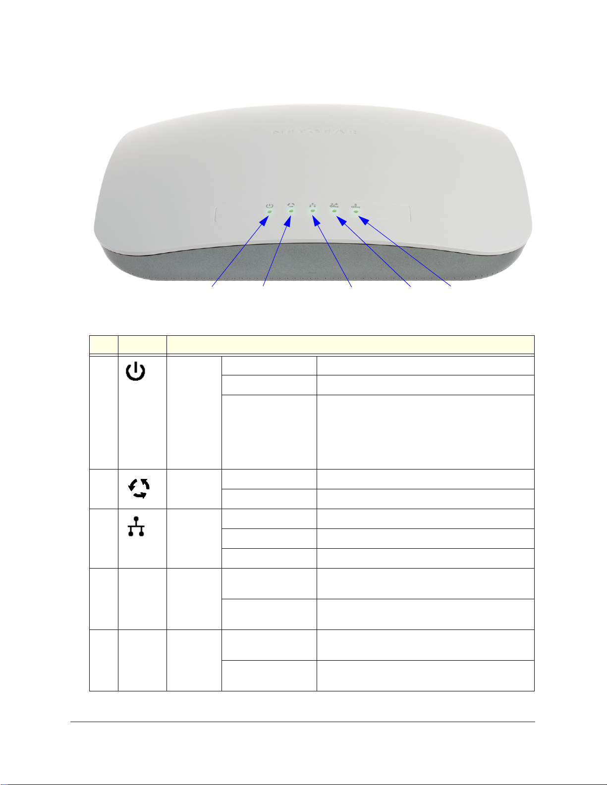
Figure 1.
1
23
4
5
ProSafe Premium 3 x 3 Dual-Band Wireless-N Access Point WNDAP620
Table 1. Top panel LEDs
Item LED Description
1 Power/Test Off Power is off.
On (green) Power is on.
Amber, then blinking
n
gree
2 Active Off No Ethernet traffic is detected, or no link is detected.
On or blinking (green) Ethernet traffic is detected.
3 LAN Off 10 Mbps or no link is detected .
Amber 10/100 Mbps link is detected.
Green 1000 Mbps link is detected.
4
2.4
WLAN Off Wireless 802.11b/g/n (2.4 GHz) LAN is not ready, or
Ghz
On or blinking (green) Wireless 802.11b/g/n (2.4 GHz) LAN is ready, or
A self-test is running or software is being loaded.
During startup, the LED is first steady amber, then
goes off, and then blinks green before turning steady
green after about 45 seconds. If after 1 minute the
ED remains amber or continues to blink green, it
L
indicates a system fault.
no wireless activity is detected.
wireless activity
is detected.
5
5
Ghz
WLAN Off Wireless 802.11n/a (5 GHz) LAN is not ready, or no
wireless activity is detected.
On or blinking (green) Wireless 802.11n/a (5 GHz) LAN is ready, or wireless
tivity is detected.
ac
Introduction
12
Page 13
ProSafe Premium 3 x 3 Dual-Band Wireless-N Access Point WNDAP620
1
2
3
4
5
6
7
8
Rear Panel
Figure 2.
The rear panel components of the wireless access point, from left to right, are described in
the following list:
1. First reverse
2. Factory def
SMA connector for an optional 2.4 GHz antenna.
ault Reset button. Using a sharp object, press and hold this button for about
5 seconds to reset the wireless access point to factory defaults settings. All configuration
ttings are lost, and the default password is restored. For more information, see Restore
se
the Wireless Access Point to the Factory Default Settings on p
3. 10/100
/1000BASE-T Gigabit Ethernet (RJ-45) port with Auto Uplink (Auto MDI-X) with
age 71.
IEEE 802.3af Power over Ethernet (PoE) support for connection to a switch or router.
4. Second
5. Console
reverse SMA connector for an optional 2.4 GHz antenna.
port for connecting to an optional console terminal. The port has an RJ-45
connector and supports the following settings: 9600 K default baud rate, 8 data bits, no (N)
parity bit, and one (1) stop bit.
6. Cable
7. Power socket for a 12 VDC,
8. Third re
security lock receptacle for an optional lock.
1.5A power adapter.
verse SMA connector for an optional 2.4 GHz antenna.
Note: The wireless access point can support up to three optional 2.4 GHz
antennas.
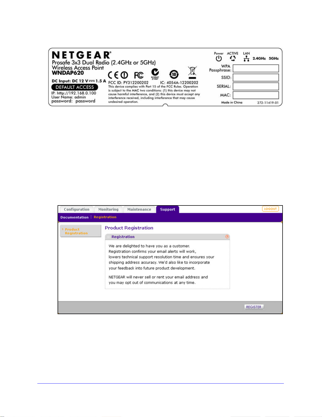
Bottom Panel with Product Label
The product label on the bottom of the wireless access point’s enclosure displays factory
default settings, regulatory compliance, and other information:
Introduction
13
Page 14
ProSafe Premium 3 x 3 Dual-Band Wireless-N Access Point WNDAP620
Figure 3.
Register the Wireless Access Point
To qualify for product updates and product warranty, NETGEAR encourages you to register
your product. The first time that you connect to the wireless access point while it is connected
to the Internet, you have the option to register your product. At any time, you can register
your product from the web management interface, or you can go to the NETGEAR website
for registration at https://my.netgear.com/registration/login.aspx.
To register the wireless access point with NETGEAR:
1. Select Support > Registration. The Product Registration screen d
Figure 4.
2. Click Register. A new screen displays in your browser:
isplays:
Introduction
14
Page 15
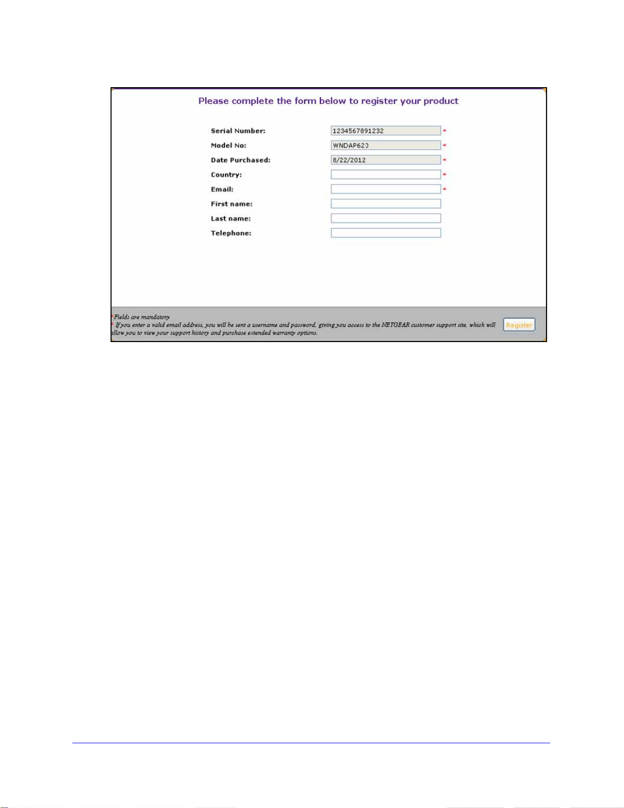
ProSafe Premium 3 x 3 Dual-Band Wireless-N Access Point WNDAP620
Figure 5.
3. Enter the information in the blank fields. The serial number, model number, and date of
purchase are entered automatically.
4. Click Regi
ster. The registration web page displays:
Introduction
15
Page 16
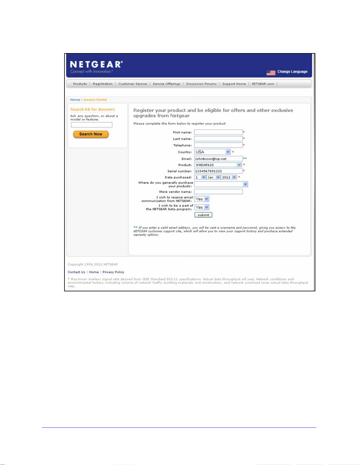
ProSafe Premium 3 x 3 Dual-Band Wireless-N Access Point WNDAP620
Figure 6.
5. Complete the registration form.
6. Click su
bmit.
Introduction
16
Page 17

2. Installation and Basic Configuration
This chapter describes how to install and configure the wireless access point for wireless
connectivity to your LAN. This basic configuration enables computers with either 2.4 GHz
802.11b/g/n or 5 GHz 802.11a/n wireless adapters to connect to the Internet or access printers
and files on your LAN. In planning your wireless network, consider the level of security required.
Chapter 3, Wireless Configuration and Security, describes how to set up wireless security for
your network. This chapter includes the following sections:
• What You Need Before You Begin
• Install and Configure the Wireless Access Point
• Test Basic Wireless Connectivity
• Mount the Wireless Access Point
What You Need Before You Begin
2
• Wireless Equipment Placement and Range Guidelines
• Ethernet Cabling Requirements
• LAN Configuration Requirements
• Hardware Requirements for Computers on Your LAN
• Operating Frequency (Channel) Guidelines
• Requirements for Entering IP Addresses
You need to consider the following guidelines an
wireless access point. See also System Requirements on p
d requirements before you can set up your
age 8.
Wireless Equipment Placement and Range Guidelines
The range of your wireless connection can vary significantly based on the location of the
wireless access point. The latency , dat a throughput performance, and power consumption of
wireless adapters also vary depending on your configuration choices.
17
Page 18

ProSafe Premium 3 x 3 Dual-Band Wireless-N Access Point WNDAP620
Note: Failure to follow these guidelines can result in significant
performance degradation or inability to connect wirelessly to the
wireless access point. For complete performance specifications, see
Appendix A, Supplemental Information.
Note: Before you position and mount the wireless access point at its
permanent position, first configure the wireless access point and test
the computers on your LAN for wireless connectivity as explained in
this chapter.
For best results, place your wireless access point according to the following general
guidelines:
• Near the
• In an elevated lo
line-of-sight access (even if through walls).
• A
way from sources of interference, such as computers, microwaves ovens, and 2.4 GHz
cordless phones.
• A
way from large metal surfaces or water.
• Placing a
Placing an external antenna in a horizontal position provides best up-and-down coverage.
(An external antenna does not come standard with the wireless access point.)
• If you are
points use different radio frequency channels to reduce interference. The recommended
channel spacing between adjacent wireless access points is five channels (for example,
use Channels 1 and 6, or 6 and 11, or 1 and 11).
The time it takes to establish a wireless connection
settings and placement. WEP connections can take slightly longer to establish. Also, WEP
encryption can consume more battery power on a notebook computer.
center of the area in which the wireless devices will operate.
cation such as a high shelf where the wirelessly connected devices have
n external antenna in a vertical position provides best side-to-side coverage.
using multiple wireless access points, it is better if adjacent wireless access
can vary depending on both your security
Ethernet Cabling Requirements
The wireless access point connects to your LAN using twisted-p air Category 5 Ethernet cable
with RJ-45 connectors.
LAN Configuration Requirements
For the initial configuration of your wireless access point, you need to connect a computer to
the wireless access point.
Installation and Basic Configuration
18
Page 19

ProSafe Premium 3 x 3 Dual-Band Wireless-N Access Point WNDAP620
Hardware Requirements for Computers on Your LAN
To connect to the wireless access point on your network, each computer needs to have an
802.11b/g/n or 802.11a/n wireless adapter installed. NETGEAR recommends using the
wireless access point with computers that have the NETGEAR N600 Wireless Dual Band
USB Adapter (WNDA3100) installed.
Operating Frequency (Channel) Guidelines
You do not need to change the operating frequency (channel) unless you notice interference
problems or you place the wireless access point near another wireless access point. If you do
change the operating frequency, observe the following guidelines:
ireless access points use a fixed channel. You can select a channel that provides the
• W
least interference and best performance. In the United States and Canada, 11 channels
re available.
a
• I
f you use multiple wireless access points, it is better if adjacent wireless access points
use different channels to reduce interference. The recommended channel spacing
between adjacent wireless access points is 5 channels (for example, use channels 1 and
6, or 6 and 11).
• I
n infrastructure mode (which is the default mode for the wireless access point), wireless
stations normally scan all channels, looking for a wireless access point. If more than one
wireless access point can be used, the one with the strongest signal is used. This is
possible only if the wireless access points use the same SSID.
Requirements for Entering IP Addresses
IPv4
The fourth octet of an IP address needs to be between 0 and 255 (both inclusive). This
requirement applies to any IP address that you enter on a screen of the web management
interface.
IPv6
IPv6 addresses are denoted by eight groups of hexadecimal quartets that are separated by
colons. Any four-digit group of zeroes within an IPv6 address can b e reduced to a single zero
or altogether omitted.
The following errors invalidate an IPv6 address:
• More t
• More t
• More t
han eight groups of hexadecimal quartets
han four hexadecimal characters in a quartet
han two colons in a row
Installation and Basic Configuration
19
Page 20

ProSafe Premium 3 x 3 Dual-Band Wireless-N Access Point WNDAP620
Install and Configure the Wireless Access Point
Install and configure your wireless access point in the order of the following sections:
1. Connect the Wireless Access Point to a Computer
2. Log In to the Wireless Access Point
3. Configure Basic General System Settings
4. Configure the IPv4 Settings
5. Configure the Optional DHCPv4 Server
6. Configure the Basic Wireless Settings
Before installing the wireless access point, make sure that your Ethernet network functions.
Af
ter you have connected the wireless access point to the Ethernet network, computers with
either 802.11b/g/n or 802.11a/n wireless adapters are able to communicate with the Ethernet
network.
For this to work correctly, verify that you have met all the system requirements, shown in
System Requirements o
n page 8.
and Time Settings
Connect the Wireless Access Point to a Computer
Tip: Before you place the wireless access point in an elevated position that is
difficult to reach, first set up and test the wireless access point to verify
wireless network connectivity.
To set up the wireless access point:
1. Unp
2. Prep
3. Connect an Ethern
4. Securely insert
.
ack the box and verify the contents.
are a computer with an Ethernet adapter. If this computer is already part of your
network, record its TCP/IP configuration settings. Configure the computer with a static IP
address of 192.168.0.210 and 255.255.255.0 as the sub net mask.
et cable from the wireless access point to the computer (point A in the
following figure).
the other end of the cable into the wireless access point’s Ethernet port
(point B in the following figure).
Installation and Basic Configuration
20
Page 21

Figure 7.
A
B
Ethernet cable
Ethernet port
2.4
Ghz
5
Ghz
ProSafe Premium 3 x 3 Dual-Band Wireless-N Access Point WNDAP620
5. Turn on your computer.
6. Conn
7. V
ect the power adapter to the wireless access point.
Tip: T
erify the following:
(steady green). If after 1 minute the Power/Test LED is not lit or is still blinking,
check the connections and see if the power outlet is controlled by a wall switch
that is turned off.
he wireless access point supports Power over Ethernet (PoE). If you
have a switch that provides PoE, you do not need to use the power
adapter to power the wireless access point. Using PoE can be especially
convenient when the wireless access point is installed in a high location
far away from a power outlet.
Power/T est LED.
first turned on. (To be exact, during startup, the LED is first steady amber, then
oes off, and then blinks green.) After about 45 seconds, the LED should stay lit
g
Active LED.
LAN LED. The L
for 100 Mbps, and no light for 10 Mbps. If the LAN LED is not lit, make sure that
t
he Ethernet cable is securely attached at both ends.
The Power/Test LED blinks when the wireless access point is
The Active LED is lit or blinks green when there is Ethernet traffic.
AN LED indicates the LAN speed: green for 1000 Mbps, amber
WLAN LED.
(WLAN) is ready.
WLAN LED.
(WLAN) is ready.
The 2.4 GHz WLAN LED is lit or blinks green when the wireless LAN
The 5 GHz WLAN LED is lit or blinks green when the wireless LAN
Installation and Basic Configuration
21
Page 22
ProSafe Premium 3 x 3 Dual-Band Wireless-N Access Point WNDAP620
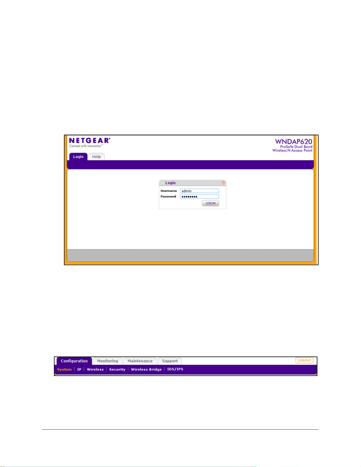
Log In to the Wireless Access Point
The default IP address of your wireless access point is 192.168.0.100. By default, the DHCP
client on the wireless access point is disabled so you can log in using the default IP address.
To log in to the wireless access point:
1. Op
en a web browser such as Microsoft Internet Explorer 6.0 or later, or Mozilla Firefox
1.5 or later.
2. Connect to
the wireless access point by entering its default address of 192.168.0.100 into
your browser (use http and not https). The Login screen displays:
Figure 8.
3. Enter the default user name of admin and the default password of p assword.
4. Click Log
Configuration tab of the main menu as shown in Figure 11 on p
in. The web browser displays the basic General system settings screen under the
age 23.
Web Management Interface
The navigation tabs across the top of the web management interface provide access to all
the configuration functions of the wireless access point and remain constant. The menu items
in the blue bar change according to the navigation tab that is selected.
Figure 9.
The bottom right corner of all screens that allow you to make configuration changes show the
Apply and Cancel buttons, and on several screens the Edit button.
Installation and Basic Configuration
22
Page 23
ProSafe Premium 3 x 3 Dual-Band Wireless-N Access Point WNDAP620
Figure 10.
These buttons have the following functions:
• Edit. Allows you
• Canc
• App
el. Cancels all configuration changes that you made on the screen.
ly . Saves and applies all configuration changes that you made on the screen.
to edit the existing configuration.
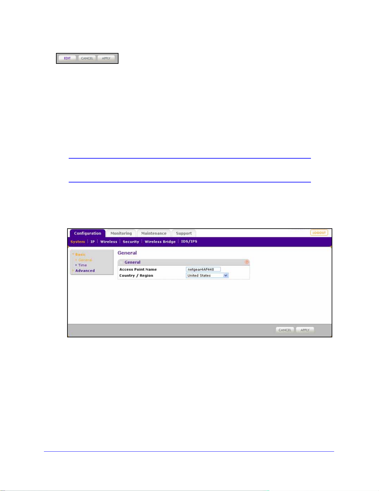
Configure Basic General System Settings and Time Settings
Note: After you have successfully logged in to the wireless access point,
the basic General system settings screen displays.
To configure basic system settings:
1. Select Configurati
screen displays:
on > System > Basic > Gen er al. The basic General system settings
Figure 11.
Installation and Basic Configuration
23
Page 24
ProSafe Premium 3 x 3 Dual-Band Wireless-N Access Point WNDAP620
2. Configure the settings as explained in the following table:
Table 2. Basic general system settings
Setting Description
Access Point Name This unique name is the wireless access poi
on the rear label of the wireless access point. The default is netgearxxxxxx, in which
xxxxxx represents the last 6 digits of the wireless access point MAC address. You
can replace the default name with a unique name up to 15 characters long. The
access point name can be retrieved through SNMP.
Country / Region From the Country / Region drop-down list, sele
access point is installed.
Note: It might not be legal to operate this wireless access point in a region other than
of those identified in this field.
one
3. Click Apply
to save your settings.
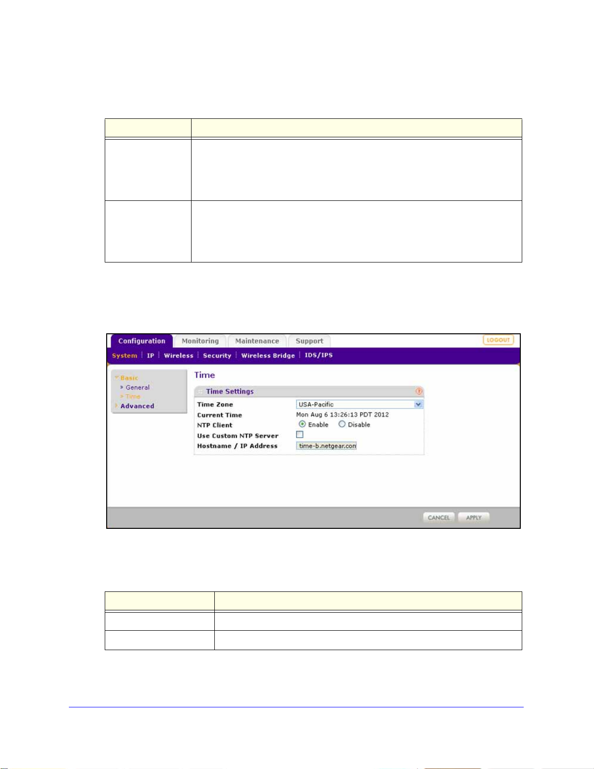
To configure time settings:
1. Select Confi
guration > System > Basic > Tim e. The Time screen displays:
nt NetBIOS name. The name is printed
ct the country where the wireless
Figure 12.
2. Configure the settings as explained in the following table:
Table 3. Time system settings
Setting Description
Time Zone Select the time zone to
Current Time This is a nonconfigurable field that
Installation and Basic Configuration
match your location.
displays the current date and time.
24
Page 25

ProSafe Premium 3 x 3 Dual-Band Wireless-N Access Point WNDAP620
WARNING:
Table 3. Time system settings (continued)
Setting Description
NTP Client Enable the Network Time Protocol (NTP) client to synchronize the time of the
wireless access point with an NTP server. By default the Enable radio button is
selected.
Use Custom NTP Server Select this check box if you want
Note: You need to have an Internet connection to use an NTP server that is
not on your lo
Hostname /
IP Address
cal network.
Enter the host name or IP address of the custom NTP server.
The default is time-b.netgear.com.
Note: If you use a host name, make sure that you have
ured a DNS server. For more information, see the next
config
section.
to use a custom NTP server.
3. Click Apply to save your settings.
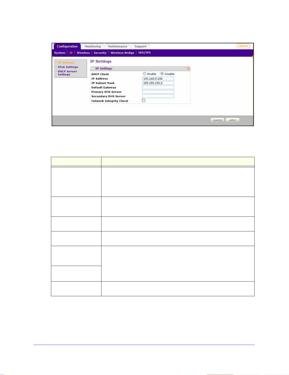
Configure the IPv4 Settings
Note: For information about how to configure the IPv6 settings, see
Configure the IPv6 Settings on page 99.
If you enable the DHCP client, the IP address of the wireless
access point changes when you click Apply, causing you to lose
your connection to the wireless access point. You then need to
use the new IP address to reconnect to the wireless access point.
Tip: If you enable the DHCP client on the wireless access point, you can
discover the new IP address of the wireless access point by accessing
the DHCP server on your LAN, or by using a network IP address scanner
application.
To configure the IPv4 settings:
1. Select Con
figuration > IP > IP Settings. The IP Settings screen displays:
Installation and Basic Configuration
25
Page 26
ProSafe Premium 3 x 3 Dual-Band Wireless-N Access Point WNDAP620
Figure 13.
2. Configure the IPv4 settings as explained in the following table:
Table 4. IPv4 settings
Setting Description
DHCP Client By default, the Dynamic Host Configuration Protocol (DHCP) client is disabled. If
you have a DHCP server on your LAN and you select the Enable check box, the
wireless access point receives its IP address, subnet mask, and default gateway
settings automatically from the DHCP server on your network when you connect
the wireless access point to your LAN.
IP Address Enter the IP address of your wireless access
192.168.0.100. T o change the address, enter an unused IP address from the
address range used on your LAN, or enable DHCP the server.
IP Subnet Mask Enter the network number portion of an IP ad
implementing subnetting, enter 255.255.0.0 as the subnet mask.
Default Gateway Enter the IP address of the ISP gateway to wh
connects.
Primary DNS Server
Secondary DNS Server
Network Integrity Check Select this check box to validate that the up
Enter the IP address of the primary and
A DNS server is a host on the Internet th
www.netgear.com) to numeric IP addresses. Typically your ISP transfers the IP
address of one or two DNS servers to your wireless access point during login. If
the ISP does not transfer an address, you need to obtain it from the ISP and
enter it manually in this field.
wireless associations. Ensure that the default gateway is configured.
point. The default IP address is
dress. Unless you are
ich the wireless access point
secondary DNS servers.
at translates Internet names (such as
stream link is active before allowing
3. Click Apply
to save your settings.
Installation and Basic Configuration
26
Page 27
ProSafe Premium 3 x 3 Dual-Band Wireless-N Access Point WNDAP620
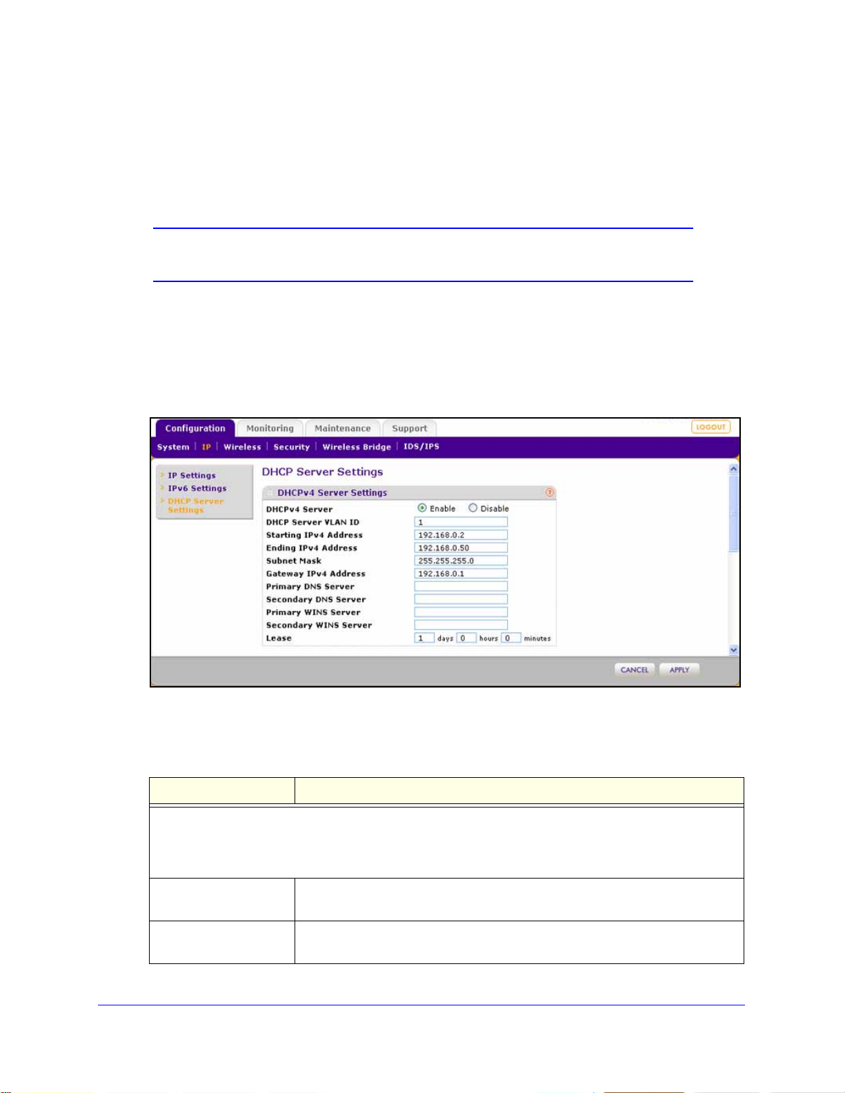
Configure the Optional DHCPv4 Server
The wireless access point provides a built-in DHCPv4 server for wireless clients only, which
can be especially useful in small networks. When the DHCP server is enabled, the wireless
access point provides preconfigured TCP/IP configurations to all connected wireless stations.
Note: For information about how to configure the DHCPv6 server, see
Configure the Optional DHCPv6 Server on page 101.
To configure DHCPv4 server settings:
1. Select Configuration
> IP > DHCP Server Settings. The DHCP Server Settings screen
displays. The following figure displays the DHCPv4 server settings only. For information
about the DHCPv6 server settings, see Configure the Optional DHCPv6 Server on
page 101.
Figure 14.
2. Configure the settings as explained in the following table:
Table 5. DHCP server settings for IPv4
Setting Description
Select the D
pool of IPv4 addresses to be assigned by setting the starting IPv4 address and ending IPv4 address. These
addresses should be part of the same IPv4 address subnet as the wireless access point’s LAN IPv4
address.
DHCP Server VLAN ID Enter the VLAN ID for the DHCP server. The VLAN ID ran
Starting IPv4 Address Enter the first address in the range of IPv4 addresses to be assigned to DHCP
HCPv4 Server check box to enable the DHCP server. Use the default settings or specify the
ge is from 1 to 4094.
The default VLAN is 1.
cl
ients. The default address is 192.168.1.02.
Installation and Basic Configuration
27
Page 28

ProSafe Premium 3 x 3 Dual-Band Wireless-N Access Point WNDAP620
WARNING:
Table 5. DHCP server settings for IPv4 (continued)
Setting Description
Ending IPv4 Address Enter the last address in the range of IPv4 addresses to be assigned to DHCP
clients. The default address is 192.168.1.50.
Subnet Mask Enter the subnet mask to be used by DHCP clients. The default mask is
5.255.255.0.
25
Gateway IPv4 Address Enter the IPv4 address of the default routing gateway to be used by DHCP
clients. The default address is 192.168.0.1.
Primary DNS Address Enter the IP address of the primary Domain Name System (DNS) server
ilable to DHCP clients.
ava
Secondary DNS Address Enter the IP address of the secondary DNS server available to DHCP clients.
Primary WINS Server Enter the IP address of the primary WINS se
Secondary WINS Server Enter the IP address of the secondary WINS server for the network, if there is
any.
Lease Enter the period that the DHCP server grants to DHCP clients to use the
gned IP addresses. The default time is one day.
assi
rver for the network, if there is any.
3. Click Apply to save your settings.
Configure the Basic Wireless Settings
For proper compliance and compatibility between similar products in your coverage area, you
need to configure the 802.11b/g/n or 802.11a/n wireless adapter settings correctly, including
the operating channel and country. You also need to configure the basic wireless network
settings for wireless devices to connect to your network. For other wireless features,
including wireless security, see Chapter 3, Wireless Configuration and Security.
If you configure the wireless access point from a wireless
computer and you change the wireless access point’s SSID,
channel, or wireless security settings, you lose your wireless
connection when you click Apply. You then need to change the
wireless settings of your computer to match the wireless access
point’s new settings.
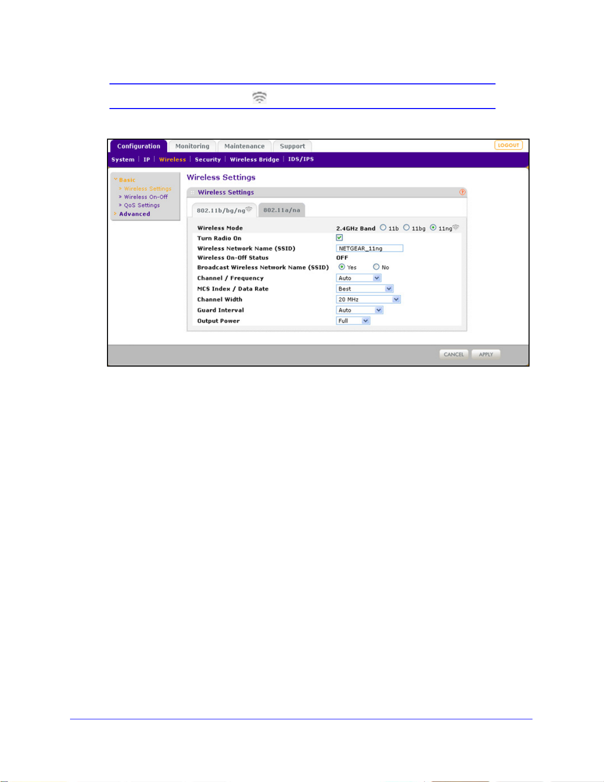
Configure 802.11b/bg/ng Wireless Settings
To configure the 802.11b/g/n wireless settings:
1. Select Configuration
Settings screen displays. (The following figure shows the 11ng settings.)
> Wireless > Basic > Wireless Settings. The basic Wireless
Installation and Basic Configuration
28
Page 29
ProSafe Premium 3 x 3 Dual-Band Wireless-N Access Point WNDAP620
Note: The radio wave icon ( ) displays next to the enabled wireless mode.
Figure 15.
2. Spe cify the wireless mode in the 2.4 GHz band by selecting one of the following radio
buttons:
b. Both 802.11n- and 802.11g-compliant devices can connect to the access point
• 11
because they are backward compatible.
•
11bg. 802.11n-compliant devices can connect to the access point because they are
backward compatible.
• 1
1ng. This is the default setting. 802.11b-compliant devices cannot connect to the
access point. If you keep the default setting, go to Step 5.
When you change the wireless mode, the Turn Radio On check box is automatically
cle
ared, and all fields, buttons, and drop-down lists onscreen are masked out.
3. T
urn on the radio by selecting the Tu rn R ad io O n ch e c k b o x. A pop-up screen displays.
Note: Under normal conditions, you want the radio to
be turned on. Turning off
the radio disables access through the wireless access point, which can be
helpful for configuration, network tuning, or troubleshooting activities.
4. Click OK
to confirm the change of wireless mode. The change does not take effect until you
click the Apply button after you have completed the wireless configuration.
Installation and Basic Configuration
29
Page 30

ProSafe Premium 3 x 3 Dual-Band Wireless-N Access Point WNDAP620
5. Specify the remaining wire less settings as explained the following table:
Table 6. Basic 2.4 GHz band wireless settings
Setting Descriptions
Wireless Network Name
(SSID)
Wireless On-Off Status This field is not configurable. It shows the status of the wireless scheduler. For
Broadcast Wireless
twork Name (SSID)
Ne
Channel / Frequency From the drop-down list, select the channel you wish to use for your wireless
Enter a 32-character (maximum) service set i
case-sensitive. The default is NETGEAR_11ng. The SSID assigned to a wireless
device needs to match the wireless access point’s SSID for the wireless device
to communicate with the wireless access point. If the SSIDs do not match, you
do not get a wireless connection to the wireless access point.
e information, see Schedule the Wireless Radio to Be Turned Off on
mor
page 61.
Select the Yes radio button to enable the wireless access point to broadcast its
SSID, allowing wireless stations that have a null (blank) SSID to adopt the
wireless access point’s SSID. Yes is the default setting. To prevent the SSID
from being broadcast, select the No radio button.
AN. The wireless channels and frequencies depend on the country and
L
wireless mode. The default setting is Auto.
Note: It should not be necessary to change the wireless channel unless you
xperience interference (indicated by lost connections or slow data transfers). If
e
this happens, you might want to experiment with different channels to see which
is the best. For more information, see Operating Frequency (Channel)
Guidelines on pa
Note: For more information about available channels and frequencies, see
Technical Specifications on pa
ge 19.
ge 139.
dentifier (SSID); the characters are
11ng mode only
Note: For most
tworks, the default
ne
settings work fine.
MCS Index / Data
Ra
te
Channel Width From the drop-down list, select a channel width. The options
Guard Interval From the drop-down list, select the guard interval to protect
From the drop-down list, select a Modulation and Coding
Scheme (MCS) index and transmit data rate for the wireless
network. The default setting is Best. For a list of all options
that you can select from in 11ng mode, see Factory Default
Settings o
re Dynamic 20/40 MHz, 20 MHz, and 40 MHz. The default is
a
20 MHz. A wider channel improves the performance, but
some legacy devices can operate only in either 20 MHz or
40 MHz.
transmissio
can select Long - 800 ns. Some legacy devices can operate
only with a long guard interval.
n page 142.
ns from interference. The default is Auto, or you
Installation and Basic Configuration
30
Page 31

ProSafe Premium 3 x 3 Dual-Band Wireless-N Access Point WNDAP620
Table 6. Basic 2.4 GHz band wireless settings (continued)
Setting Descriptions
11b and 11bg modes
only
Output Power From the drop-down list, select the transmission power of the wireless access
Data Rate From the drop-down list, select the transmit data rate of the
wireless network. The default setting is Best. For a list of all
options that you can select f rom in 1 1b mode and 1 1bg mode,
see Factory Default Settings on
point: Full, Half, Quarter, Eighth, Minimum. The default is Full.
Note: Increasing the power improves performance
access points are operating in the same area and on the same channel,
interference can occur.
Note: Make sure that you comply with the regu
frequency (RF) output power in your country.
latory requirements for total radio
6. Click Apply to save your settings and enable the selected wireless mode.
Note: For information about how to configure advanced wireless settings,
see Configure Advanced Wireless Settings on page 107.
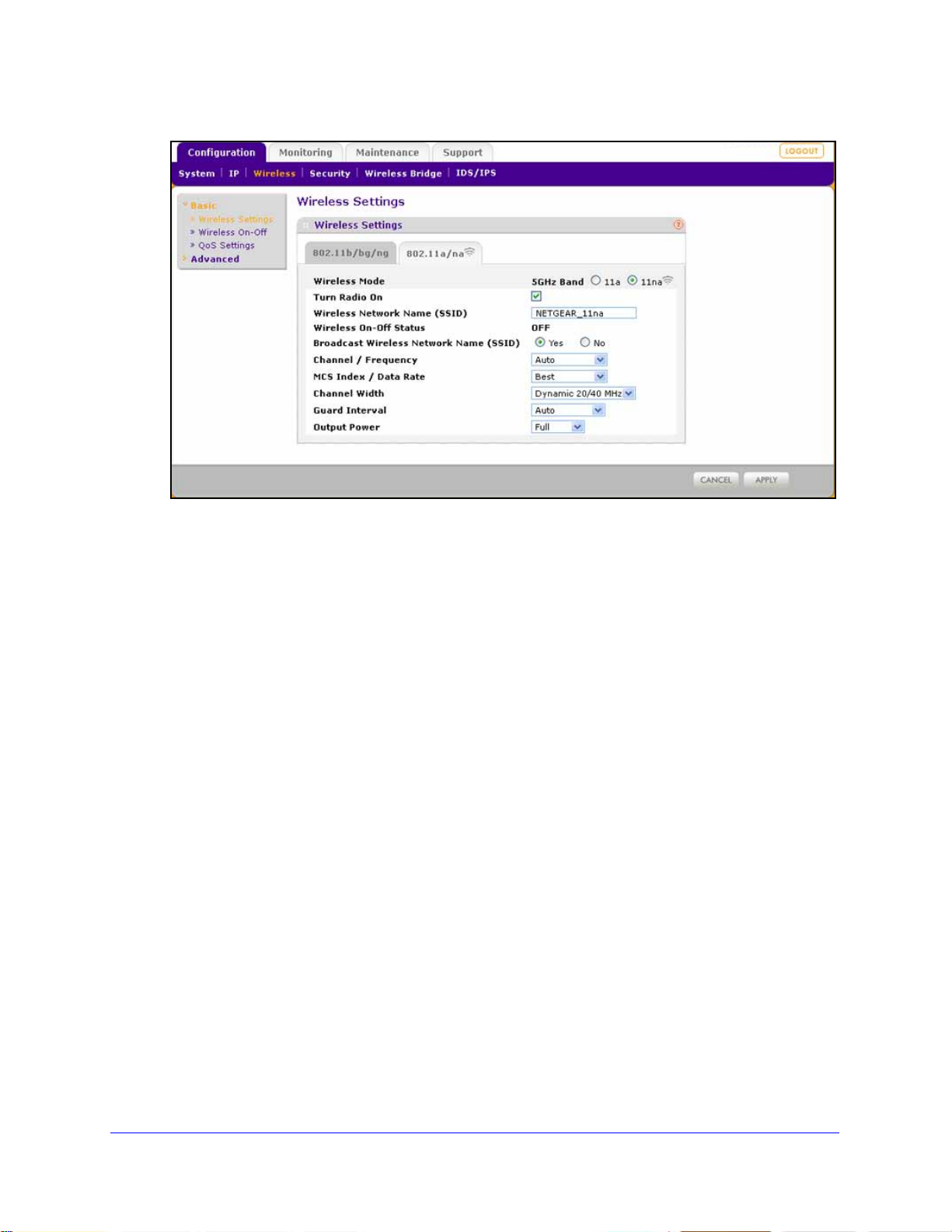
Configure 802.11a/na Wireless Settings
To configure the 802.11a/na wireless settings:
page 142.
, but if two or more wireless
1. Select Con
figuration > Wireless > Basic > Wireless Settings. The basic Wireless
Settings screen displays. (The following figure shows the 802.11na settings.)
Note: The radio wave icon ( ) displays next to the selected radio mode.
Installation and Basic Configuration
31
Page 32
ProSafe Premium 3 x 3 Dual-Band Wireless-N Access Point WNDAP620
Figure 16.
2. Specify the wireless mode in the 5 GHz band by selecting one of the following radio buttons:
• 11
a. 802.11n-compliant devices can connect to the access point because they are
backward compatible.
• 1
1na. This is the default setting. If you keep the default setting, go to Step 5.
When you change the wireless mode, the Turn Radio On check box is automatically
cleared, a
urn on the radio by selecting the Turn Radio On c he ck bo x . A pop-up screen displays.
3. T
nd all fields, buttons, and drop-down lists onscreen are masked out.
Note: Under normal conditions, you want the radio to be turned on. Turning off
the ra
dio disables access through the wireless access point, which can be
helpful for configuration, network tuning, or troubleshooting activities.
4. Click OK to confirm t
he change of wireless mode. The change does not take effect until you
click the Apply button after you have completed the wireless configuration.
Installation and Basic Configuration
32
Page 33

ProSafe Premium 3 x 3 Dual-Band Wireless-N Access Point WNDAP620
5. Spe cify the remaining wireless settings as explained the following table:
Table 7. Basic 5 GHz band wireless settings
Setting Descriptions
Wireless Network Name
(SSID)
Wireless On-Off St atus This is a nonconfigurable field that shows th
Broadcast Wireless
Network Name (SSID)
Channel / Frequency From the drop-down list, select the channel you wish to use on your wireless
11na mode only
Note: For most
networks, the
settings work fine.
default
Enter a 32-character (maximum) service set identifier (SSID); the characters are
case-sensitive. The default is NETGEAR_11na. The SSID assigned to a wireless
device needs to match the wireless access point’s SSID for the wireless device
to communicate with the wireless access point. If the SSIDs do not match, you
do not get a wireless connection to the wireless access point.
e status of the wireless scheduler.
For more information, see Schedule the Wireless Radio to Be Turned Off on
page 61.
Select the Ye
SSID, allowing wireless stations that have a null (blank) SSID to adopt the
wireless access point’s SSID. Yes is the default setting. To prevent the SSID
from being broadcast, select the No radio button.
LAN. The
wireless mode. The default setting is Auto.
Note: It should not be necessary to change the wireless channel unless you
expe
this happens, you might want to experiment with different channels to see which
is the best. For more information, see the guidelines following this table.
Note: For more information about available channels and frequencies, see
Technical Specifications on
MCS Index / Data
Rate
s radio button to enable the wireless access point to broadcast its
wireless channels and frequencies depend on the country and
rience interference (indicated by lost connections or slow data transfers). If
page 139.
From the drop-down list, select a Modulation and Coding
Scheme (MCS) in
network. The default setting is Best. For a list of all options
that you can select from in 11na mode, see Factory Default
Settings on p
dex and transmit data rate for the wireless
age 142.
Channel Width From the drop-down list, select a channel width. The options
are Dyn
Dynamic 20/40 MHz. A wider channel improves the
performance, but some legacy devices can operate only in
either 20 MHz or 40 MHz.
Guard Interval From the drop-down li st, select the gu
transmissions from interference. The default is Auto, or you
can select Long - 800 ns. Some legacy devices can operate
only with a long guard interval.
amic 20/40 MHz, 20 MHz, and 40 MHz. The default is
ard interval to protect
Installation and Basic Configuration
33
Page 34

ProSafe Premium 3 x 3 Dual-Band Wireless-N Access Point WNDAP620
Table 7. Basic 5 GHz band wireless settings (continued)
Setting Descriptions
11a mode only Data Rate From the drop-down list, select the transmit data rate of the
wireless network. The default setting is Best. For a list of all
options that you can select from in 11a mode, see Factory
Default Settings o
Output Power From the drop-down list, select the transmission power of the wireless access
point: Full, Half, Quarter, Eighth, Minimum. The default is Full.
Note: Increasing the power improves performance, but if two or more wireless
ccess points are operating in the same area and on the same channel,
a
interference can occur.
n page 142.
Note: Make sure that you comply with the regul
frequency (RF) output power in your country.
atory requirements for total radio
6. Click Apply to save your settings and enable the select ed wireless mode.
Note: For information about how to configure advanced wireless settings,
see Configure Advanced Wireless Settings on page 107.
Test Basic Wireless Connectivity
After you have configured the wireless access point as explained in the previous sections,
test the computers on your LAN for wireless connectivity before you position and mount the
wireless access point at its permanent position.
To test for wireless connectivity:
1. Config
all have the same SSID and channel that you have configured on the wireless access
point.
2. V
enabled the DHCP server on the wireless access point, verify that your computers are able
to obtain an IP address through DHCP from the wire le s s ac c es s p oi nt .
3. V
Mozilla Firefox 1.5 or later to browse the Internet, or check for file and printer access on your
network.
ure the 802.11b/g/n or 802.11a/n wireless adapters of your computers so that they
erify that your computers have a wireless link to the wir el e ss ac ce s s po i nt . I f you have
erify network connectivity by using a browser such as Internet Explorer 6.0 or later or
Note: If you have trouble connecting to the wireless access point, see
Chapter 6, Troubleshooting.
Installation and Basic Configuration
34
Page 35

ProSafe Premium 3 x 3 Dual-Band Wireless-N Access Point WNDAP620
NETGEAR recommends that you complete the following tasks before you deploy the
wireless access point in your network:
• Con
• Con
After you have completed the configuration of the
the computer that you used for this process back to its original TCP/IP settings.
figure wireless security and other wireless features as described in Chapter 3,
Wireless Configuration and Security.
figure any additional features that you might need as described in Chapter 4,
Management and Monitoring, and Chapter 5, Advanced Configuration.
wireless access point, you can reconfigure
Mount the Wireless Access Point
• Ceiling Installation
• Wall Installation
• Desk Installation
Note: NETGEAR recommends that you review the information in Wireless
Equipment Placement and Range Guidelines on p
mount the wireless access point at its permanent position.
age 17 before you
Note: The figures in the procedures in this section do not show the
WNDAP620 wireless access point. However, the procedures are
generic and do apply to the WNDAP620 wireless access point.
Ceiling Installation
The best location for ceiling installation is at the center of your wireless coverage area, and
within line of sight of all mobile devices. Make sure the top (the dome side) of the wireless
access point is directed toward the users and not the ceiling.
Installation and Basic Configuration
35
Page 36

ProSafe Premium 3 x 3 Dual-Band Wireless-N Access Point WNDAP620
Mounting plate
Clamp with screws
Note: Do not place the wireless access point in a false ceiling space facing up.
To install the wireless access point using the ceiling installation kit:
erify the package contents of the ceiling installation kit.
1. V
2. Det
3. Att
ach the mounting plate from the wireless access point.
ach the clamp to the ceiling rail.
Installation and Basic Configuration
36
Page 37

ProSafe Premium 3 x 3 Dual-Band Wireless-N Access Point WNDAP620
4. Attach the mounting plate to the clamp.
5. Conn
6. Att
ach the wireless access point to the mounting plate.
ect the cables to the wireless access point.
Installation and Basic Configuration
37
Page 38

ProSafe Premium 3 x 3 Dual-Band Wireless-N Access Point WNDAP620
7. Attach the cover to the wireless access point.
Wall Installation
The best location for wall installation is at the center of your wireless coverage area, and
within line of sight of all mobile devices. Make sure the top (the dome side) of the wireless
access point is directed toward the users and not the wall.
To install the wireless access point using the wall installation kit:
erify the package contents of the wall installation kit.
1. V
Installation and Basic Configuration
38
Page 39
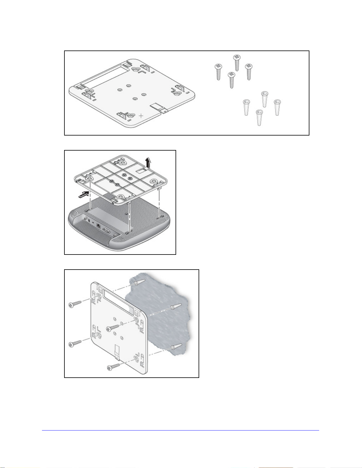
ProSafe Premium 3 x 3 Dual-Band Wireless-N Access Point WNDAP620
Mounting plate
Screws and
wall supports
2. Detach the mounting plate from the wireless access point.
3. Att
ach the mounting plate to the wall.
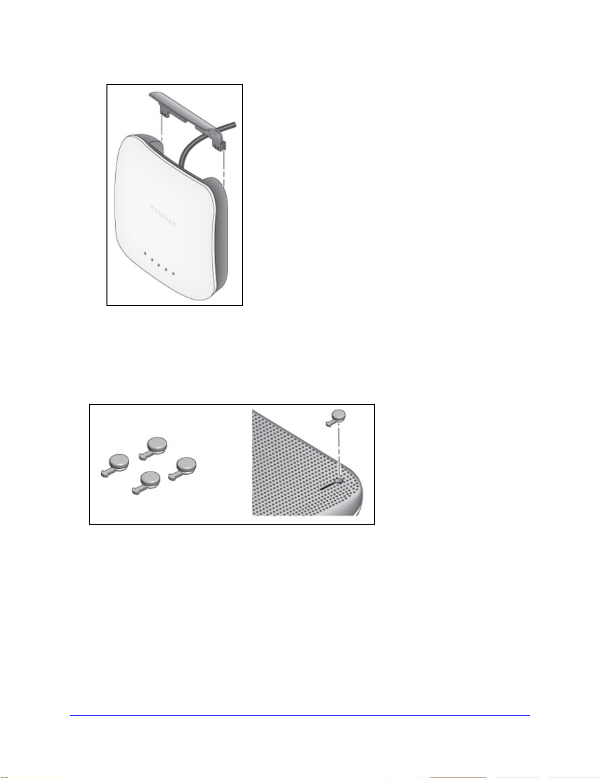
4. Conn
ect the cables to the wireless access point.
Installation and Basic Configuration
39
Page 40

ProSafe Premium 3 x 3 Dual-Band Wireless-N Access Point WNDAP620
5. Attach the wireless access point to the mou nting plate.
6. Att
ach the cover to the wireless access point.
Installation and Basic Configuration
40
Page 41
ProSafe Premium 3 x 3 Dual-Band Wireless-N Access Point WNDAP620
Rubber feet
Desk Installation
To install the wireless access point on a desk:
Attach the rubber feet to the holes in the bottom of the wireless access point.
Installation and Basic Configuration
41
Page 42

3. Wireless Configuration and Security
WARNING:
This chapter describes how to configure the wireless features of the wireless access point. The
chapter includes the following sections:
• Wireless Data Security Options
• Security Profiles
• Configure RADIUS Server Settings
• Restrict Wireless Access by MAC Address
• Schedule the Wireless Radio to Be Turned Off
• Configure Basic Wireless Quality of Service
3
Before you set up wireless security and additional wireless featu
chapter, connect the wireless access point, get the Internet connection working, and
configure the 802.11b, 11bg, or 11ng wireless settings and the 802.11a or 11na wireless
settings as described in Chapter 2, Installation and Basic Configuration. The wireless access
point functions with an Ethernet LAN connection. Make sure that you have verified wireless
conn
ectivity before you set up wireless security and additional wireless features.
If you are configuring the wireless access point from a wireless
computer and you change the wireless access point’s SSID,
channel, or wireless security settings, you lose your wireless
connection when you click Apply. You then need to change the
wireless settings of your computer to match the wireless access
point’s new settings.
res that are described in this
Wireless Data Security Options
Indoors, computers can connect over 802.11n wireless networks at a maximum range of
300 feet. Typ ically, a wireless access point inside a bu
100-foot radius. Such distances can allow for others outside your immediate area to access
your network.
ilding works best with devices within a
42
Page 43
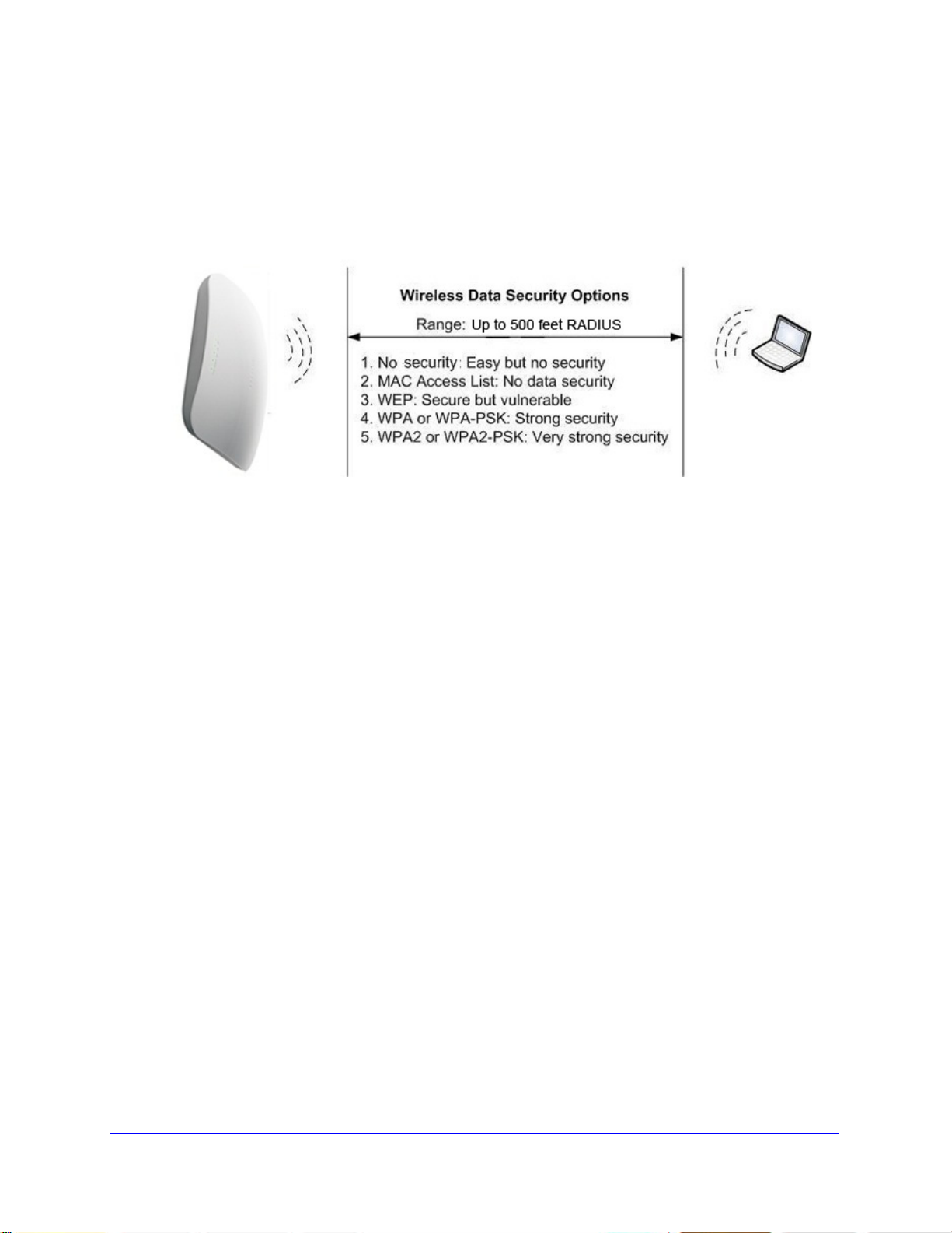
ProSafe Premium 3 x 3 Dual-Band Wireless-N Access Point WNDAP620
Unlike wired network data, your wireless data transmissions can extend beyond your walls
and can be received by anyone with a compatible adapter. For this reason, use the security
features of your wireless equipment. The wireless access point provides highly effective
security features that are covered in detail in this chapter. Deploy the security features
appropriate to your needs.
Figure 17.
There are several ways you can enhance the security of your wireless network:
• Use
multiple BSSIDs combined with VLANs. You can configure combinations of
VLANS and BSSIDs (security profiles) with stronger or less restrictive access security
according to your requirements. For example, visitors could be given wireless Internet
access but be excluded from any access to your internal network. For information about
how to configure BSSIDs, see Configure and Enable Security Profiles o
• Res
trict access based by MAC address. You can allow only trusted devices to connect
n page 48.
so that unknown devices cannot wirelessly connect to the wireless access point.
Restricting access by MAC address adds an obstacle against unwanted access to your
network, but the data broadcast over the wireless link is fully exposed. For information
about how to restrict access by MAC address, see Restrict Wireless Access by MAC
Address on p
• T
urn off the broadcast of the wireless network name (SSID). If you disable broadcast
age 60.
of the SSID, only devices that have the correct SSID can connect. This nullifies the
wireless network discovery feature of some products, such as Windows XP, but the data
is still exposed. For information about how to turn off broadcast of the SSID, see
Configure and Enable Security Profiles on p
• WE
P. Wired Equivalent Privacy (WEP) data encryption provides data security. WEP
age 48.
shared key authentication and WEP data encryption block all but the most determined
eavesdropper. This data encryption mode has been superseded by WPA-PSK and
WPA2-PSK. For information about how to configure WEP, see Configure and Enable
Security Profiles on p
with WEP on p
age 53.
age 48 and Configure an Open System with WEP or Shared Key
egacy 802.1X. Legacy 802.1X uses RADIUS-based 802.1x authentication but no data
• L
encryption. For information about how to configure Legacy 802.1X, see Configure and
Enable Security Profiles on p
age 48 and Configure Legacy 802.1X on page 54.
Wireless Configuration and Security
43
Page 44

ProSafe Premium 3 x 3 Dual-Band Wireless-N Access Point WNDAP620
• WPA and WPA-PSK (TKIP). Wi-Fi Protected Access (WPA) data encryption provides
strong data security with Temporal Key Integrity Protocol (TKIP) encryption. The very
strong authentication along with dynamic per-frame rekeying of WPA makes it virtually
impossible to compromise.
WPA uses RADIUS-based 802.1x authentication; for more information, see Configure
and Enable Security Profiles on p
RADIUS, and WPA & WPA2 with RADIUS on p
WPA-PSK uses a pre-shared key (PSK) for authentication; for more information, see
Configure and Enable Security Profiles on
WPA2-PSK, and WPA-PSK & WPA2-PSK on
age 48 and Configure WPA with RADIUS, WPA2 with
age 55.
page 48 and Configure WPA-PSK,
page 56.
• WP
• WP
A2 and WP A2-PSK (AES). Wi-Fi Protected Access versio n 2 (WPA2) data encryption
provides strong data security with Advanced Encryption Standard (AES) encryption. The
very strong authentication along with dynamic per-frame rekeying of WPA2 makes it
virtually impossible to compromise.
WPA2 uses RADIUS-based 802.1x authentication; for more information, see Configure
and Enable Security Profiles on p
RADIUS, and WPA & WPA2 with RADIUS on p
WPA2-PSK uses a pre-shared key (PSK) for authentication; for more information, see
Configure and Enable Security Profiles on
WPA2-PSK, and WPA-PSK & WPA2-PSK on
A & WP A2 and WPA-PSK & WPA2-PSK mixed modes. These modes support data
encryption either with both WPA and WPA2 clients or with both WPA-PSK and
WPA2-PSK clients and provide the most reliable security.
WPA & WPA2 uses RADIUS-based 802.1x authentication; for more information, see
Configure and Enable Security Profiles on
WPA2 with RADIUS, and WPA & WPA2 with RADIUS on p
WPA-PSK & WPA2-PSK uses a pre-shared key (PSK
information, see Configure and Enable Security Profiles on p
WPA-PSK, WPA2-PSK, and WPA-PSK & WPA2-PSK on p
age 48 and Configure WPA with RADIUS, WPA2 with
age 55.
page 48 and Configure WPA-PSK,
page 56.
page 48 and Configure WPA with RADIUS,
age 55.
) for authentication; for more
age 48 and Configure
age 56.
Security Profiles
• Before You Change the SSID, WEP, and WPA Settings
• Configure and Enable Security Profiles
Security profiles let you configure unique security
wireless access point. For each radio, the wireless access point supports up to eight security
profiles (BSSIDs) that you can configure on the individual Edit Wireless Network screens that
are accessible from the Edit Security Profile screen (see Configure and Enable Security
Profiles o
n page 48).
Wireless Configuration and Security
settings for each SSID on each radio of the
44
Page 45

ProSafe Premium 3 x 3 Dual-Band Wireless-N Access Point WNDAP620
To set up a security profile, select its network authentication type, data encryption, wireless
client security separation, and VLAN ID:
• Network authentication
The wireless access point is set by default as an open system with no authentication.
hen you configure network authentication, bear in mind that not all wireless adapters
W
support WPA or WPA2. Windows XP, Windows 2000 with Service Pack 3, and Windows
Vista do include the client software that supports WPA. However, client software is
required on the client. Consult the product documentation for your wireless adapter and
WPA or WPA2 client software for instructions about how to configure WPA2 settings.
For information about the types of network authe
supports, see Configure and Enable Security Profiles on
• Dat
a encryption
ntication that the wireless access point
page 48.
Select the data encryption that you want to use. The available options depend on the
n
etwork authentication setting described earlier (otherwise, the default is None). The data
encryption settings are explained in Configure and Enable Security Profiles on p
• W
ireless client security separation
If this feature is enabled, the associated wireless client
s (using the same SSID) are not
able to communicate with each other. This feature is useful for hotspots and other public
access situations. By default, wireless client separation is d isabled. For more information,
see Configure and Enable Security Profiles on p
age 48.
• VLAN ID
If this feature is enabled and if the network devices (hubs and switches) on your LAN
suppo
rt the VLAN (802.1Q) standard, the default VLAN ID for the wire less access point is
associated with each profile. The default VLAN ID needs to match the IDs that are used
by the other network devices. For more information, see Configure and Enable Security
Profiles on p
Some concepts and guidelines regarding the SSID a
• A basic service set (BSS) is a group of wireless st
age 48.
re explained in the following list:
ations and a single wireless access
point, all using the same security profile or service set identifier (BSSID). The actual
identifier in the BSSID is the MAC address of the wireless radio. (A wireless radio can
have multiple MAC addresses, one for each security profile.)
age 48.
• An
extended service set (ESS) is a group of wireless stations and multiple wireless
access points, all using the same identifier (ESSID).
• Dif
ferent wireless access points within an ESS can use different channels. To reduce
interference, adjacent wireless access points should use different channels.
• Roa
ming is the ability of wireless stations to connect wirelessly when they physically
move from one BSS to another one within the same ESS. The wireless station
automatically changes to the wireless access point with the least interference or best
performance.
Wireless Configuration and Security
45
Page 46

ProSafe Premium 3 x 3 Dual-Band Wireless-N Access Point WNDAP620
Before You Change the SSID, WEP, and WPA Settings
For a new wireless network, print or copy one of the following forms and fill in the settings.
For an existing wireless network, the network administrator can provide this information. Be
sure to set the country or region correctly as the first step.
Form for 802.11b/bg/ng Modes
Print this page and store the security information in a safe place:
• SSID: The
service set identifier (SSID) identifies the wireless local area network. You can
customize it by using up to 32 alphanumeric characters. Write your SSID on the line.
SSID: ___________________________________
The SSID in the wireless access point is the SSID you configure on the wireless adapter
card
. All wireless nodes in the same network need to be configured with the same SSID.
• WEP
key size and authentication
Choose the key size by circling one: 64, 128, or 152 bits.
Choose the authentication type by circling one: open system or shared key.
Passphrase: ___________________________________
Note: If you sele
ct shared key, the other devices in the network cannot connect unless
they are set to shared key and have the same keys in the same positions as those in the
wireless access point.
• WP
A-PSK (pre-shared key) and WPA2-PSK
Record the WPA-PSK passphrase:
WPA-PSK passphrase: ________________________________
Record the WPA2-PSK passphrase:
WPA2-PSK passphrase: ________________________________
• WP
A RADIUS settings
For WPA, record the following settings for the p
rimary and secondary RADIUS servers:
Server name/IP address: Primary ________________ Secondary _________________
Port: ___________________________________
Shared secret: ___________________________________
• WP
A2 RADIUS settings
For WPA2, record the following settings for the
primary and secondary RADIUS servers:
Server name/IP address: Primary ________________ Secondary _________________
Port: ___________________________________
Shared secret: ___________________________________
------------------------------------------------
Wireless Configuration and Security
End of Form--------------------------------------------------------
46
Page 47

ProSafe Premium 3 x 3 Dual-Band Wireless-N Access Point WNDAP620
Form for 802.11a/an Modes
Print this page and store the security information in a safe place:
• SSID: T
he service set identifier (SSID) identifies the wireless local area network. You can
customize it by using up to 32 alphanumeric characters. Write your SSID on the line.
SSID: ___________________________________
The SSID in the wireless access point is the SSID you configure on
the wireless adapter
card. All wireless nodes in the same network need to be configured with the same SSID.
• WEP key
size and authentication
Choose the key size by circling one: 64, 128, or 152 bits.
Choose the authentication type by circling on
e: open system or shared key.
Passphrase: ___________________________________
Note: If yo
u select shared key, the other devices in the network cannot connect unless
they are set to shared key and have the same keys in the same positions as those in the
wireless access point.
• WP
A-PSK (pre-shared key) and WP A2-PSK
Record the WPA-PSK passphrase:
WPA-PSK passphrase: ________________________________
Record the WPA2-PSK passphrase:
WPA2-PSK passphrase: ________________________________
• WP
A RADIUS settings
For WPA, record the following settings for the primary and secondary RADIUS servers:
Server name/IP address: Primary ________________ Secondary _________________
Port: ___________________________________
Shared secret: ___________________________________
• WP
A2 RADIUS settings
For WPA2, record the following settings for the primary and secondary RADIUS servers:
Server name/IP address: Primary ________________ Secondary _________________
Port: ___________________________________
Shared secret: ___________________________________
------------------------------------------------
End of Form--------------------------------------------------------
Wireless Configuration and Security
47
Page 48
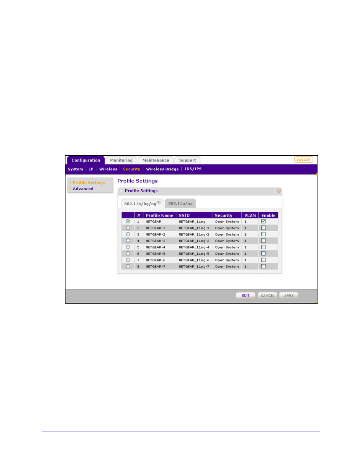
ProSafe Premium 3 x 3 Dual-Band Wireless-N Access Point WNDAP620
Configure and Enable Security Profiles
To configure and enable a security profile, you need to enable the associated radio:
• For 80
802.11b/bg/ng Wireless Settings on p
• F
Wireless Settings on
To configure and enable a security profile:
1. Select Config
2.11b/bg/ng modes, the 2.4 GHz radio needs to be enabled (see Configure
age 28).
or 802.11a/na modes, the 5 GHz radio needs to be enabled. (see Configure 802.11a/na
page 31).
uration > Security > Profile Settings. The Profile Settings screen for the
802.11b/bg/ng modes displays, showing eight wireless security profiles. (If the 2.4 GHz
radio is disabled, the Enable column is masked out.)
Figure 18.
2. Optional: To display the Prof ile Settings screen for the 802.11a/na modes, click the
802.11a/na tab. This screen also shows eight wireless security profiles. (If the 5 GHz radio is
disabled, the Enable column is masked out.)
Wireless Configuration and Security
48
Page 49

ProSafe Premium 3 x 3 Dual-Band Wireless-N Access Point WNDAP620
Figure 19.
The following table explains the fields of the Profile Settings screen:
Table 8. Profile settings
Setting Description
Profile Name The unique name of the wireless security profile that makes it easy to
recognize the profile.
SSID The wireless network name (SSID) for the wireless security profile.
Security The configured wireless authentication method for the wireless security
file.
pro
VLAN The default VLAN ID that is associated with the wireless security profile.
Enable The check box that lets you select the wireless security profile so you can
able it by clicking Apply.
en
o configure a wireless security profile, select the corresponding radio button to the left of
3. T
the wireless security profile. The Edit Security Profile screen opens for the selected wireless
security profile (see the following figure). The screen has three sections:
• Pro
• Aut
file Definition (see Step 4)
hentication Settings (see Step 5)
• QoS Policies (see Step 6)
Wireless Configuration and Security
49
Page 50

ProSafe Premium 3 x 3 Dual-Band Wireless-N Access Point WNDAP620
Figure 20.
4. Specify the settings of the Profile Definition section of th e Edit Security Profile screen as
explained in the following table:
Table 9. Profile definition settings
Setting Description
Profile Name Enter a unique name of the wireless security profile
recognize the profile. The default names are NETGEAR, NETGEAR-1,
NETGEAR-2, and so on, through NETGEAR-7. You can enter a value of up to
32 alphanumeric characters.
Wireless Network Name
(SSID)
The wireless network name (SSID) for the
names depend on the selected radio band:
02.11b/bg/ng. The default names are NETGEAR_11ng,
• 8
NETGEAR_11ng-1, NETGEAR_11ng-2, and so on, through
NETGEAR_11ng-7 for the eighth profile.
.11a/na. The default names are NETGEAR_11na, NETGEAR_11na-1,
• 802
NETGEAR_11na-2, and so on, through NETGEAR_11na-7 for the eighth
profile.
wireless security profile. The default
that makes it easy to
Wireless Configuration and Security
50
Page 51

ProSafe Premium 3 x 3 Dual-Band Wireless-N Access Point WNDAP620
Table 9. Profile definition settings (continued)
Setting Description
Broadcast Wireless
Network Name (SSID)
Select the Yes radio button to enable the wireless access point to broadcast its
SSID, allowing wireless stations that have a null (blank) SSID to adopt the
wireless access point’s SSID. Yes is the default setting. To prevent the SSID
from being broadcast, select the No radio button.
5. Spe cify the settings of the Authentication Set tings section of the Edit Security Profile screen
as explained in the following table.
The wireless access point is set by default as an open system with no authentication.
W
hen you configure network authentication, bear in mind the following:
f you are using access point mode (which is the default mode if you did not enable
• I
wireless bridging), then all options are available. In other modes such as bridge
mode, some options might be unavailable.
• Not
all wireless adapters support WPA or WPA2. Windows XP, Windows 2000 with
Service Pack 3, and Windows Vista do include the client sof tware that support s WPA.
However, client software is required on the client. Consult the product documentation
for your wireless adapter and WP A or WPA2 client software for instructions about how
to configure WPA2 settings.
Table 10. Profile authentica tio n se tti n gs
Setting Description
Network Authentication
and Data Encryption
Note: The data
encryption
display onscreen
depend on your
selection from the
Network Authentication
drop-down list.
fields that
Open System This is the default setting. Use an op
encryption or with WEP encryption.
See Configure an Open System with WEP or Shared Key
with WEP on p
Shared Key Use WEP encryption and enter at
See Configure an Open System with WEP or Shared Key
with WEP on page 53.
Legacy 802.1X Configure the RADIUS server settings. En
supported.
See Configure Legacy 802.1X on
age 53.
en system without any
least one shared key.
cryption is not
page 54.
WPA with Radius Configure the RADIUS server settings and select TKIP or
TKIP + AE
See Configure WPA with RADIUS, WPA2 with RADIUS,
and WPA & WPA2 with RADIUS o
WPA2 with Radius Configure the RADIUS server settings and select AES or
TKIP + AES encryption.
See Configure WPA with RADIUS, WP
and WPA & WPA2 with RADIUS on page 55.
Note: Select this setting only if all clients support WPA2.
Wireless Configuration and Security
51
S encryption.
n page 55.
A2 with RADIUS,
Page 52

ProSafe Premium 3 x 3 Dual-Band Wireless-N Access Point WNDAP620
Table 10. Profile authentication settings (continued)
Setting Description
Network Authentication
and Data Encryption
(continued)
WPA & WP A2 with
Radius
WPA-PSK Enter a WPA passphrase and select TKIP or TKIP + AES
WPA2-PSK Enter a WPA passphrase and select AES or TKIP + AES
WPA-PSK &
A2-PSK
WP
Configure the RADIUS server setting. TKIP + AES
encryption is the default encryption.
See Configure WPA with RADIUS, WPA2 with RADIUS,
and WPA & WPA2 with RADIUS on
Note: This setting allows clients to connect through either
with TKIP or WPA2 with AES.
WPA
encryption.
See Configure WPA-PSK, WPA2-PSK, and WP
WPA2-PSK on page 56.
encryption.
See Configure WPA-PSK, WPA2-PSK, and WP
WPA2-PSK on
Note: Select this setting only if all clients support WPA2.
Enter a WPA passphrase. TKIP + AES encryption is the
default encryption.
See Configure WPA-PSK, WPA2-PSK, and WPA-PSK &
WPA2-PSK on
Note: This setting allows clients to connect through either
WPA with TKIP or WPA2 with AES.
page 56.
page 56.
page 55.
A-PSK &
A-PSK &
Wireless Client Security
aration
Sep
VLAN ID Enter the VLAN ID to be associated with this wireless security profile. The
If you enable wireless client security separation by selecting Enable from the
drop-down list, the associated wireless clients cannot communicate with each
other. By default, Disable is selected from the drop-down list. This feature is
intended for hotspots and other public access situations.
t VLAN ID is 1. The VLAN ID needs to match the VLAN ID that is used by
defaul
the other devices in your network.
6. Optional: In the QoS Policies section of the screen, select a QoS policy from the Incoming
drop-down list, Outgoing drop-down list, or both. Depending on your selection, the policy is
applied to incoming packets, outgoing packets, or both incoming and outgoing packets, and
is displayed in the Policy Details fields.
Note: To be able to select a QoS policy, you first need to have configured one
or more policies (see
7. Click Apply to save
Configure Quality of Service Policies o
your settings.
n page 112).
Wireless Configuration and Security
52
Page 53
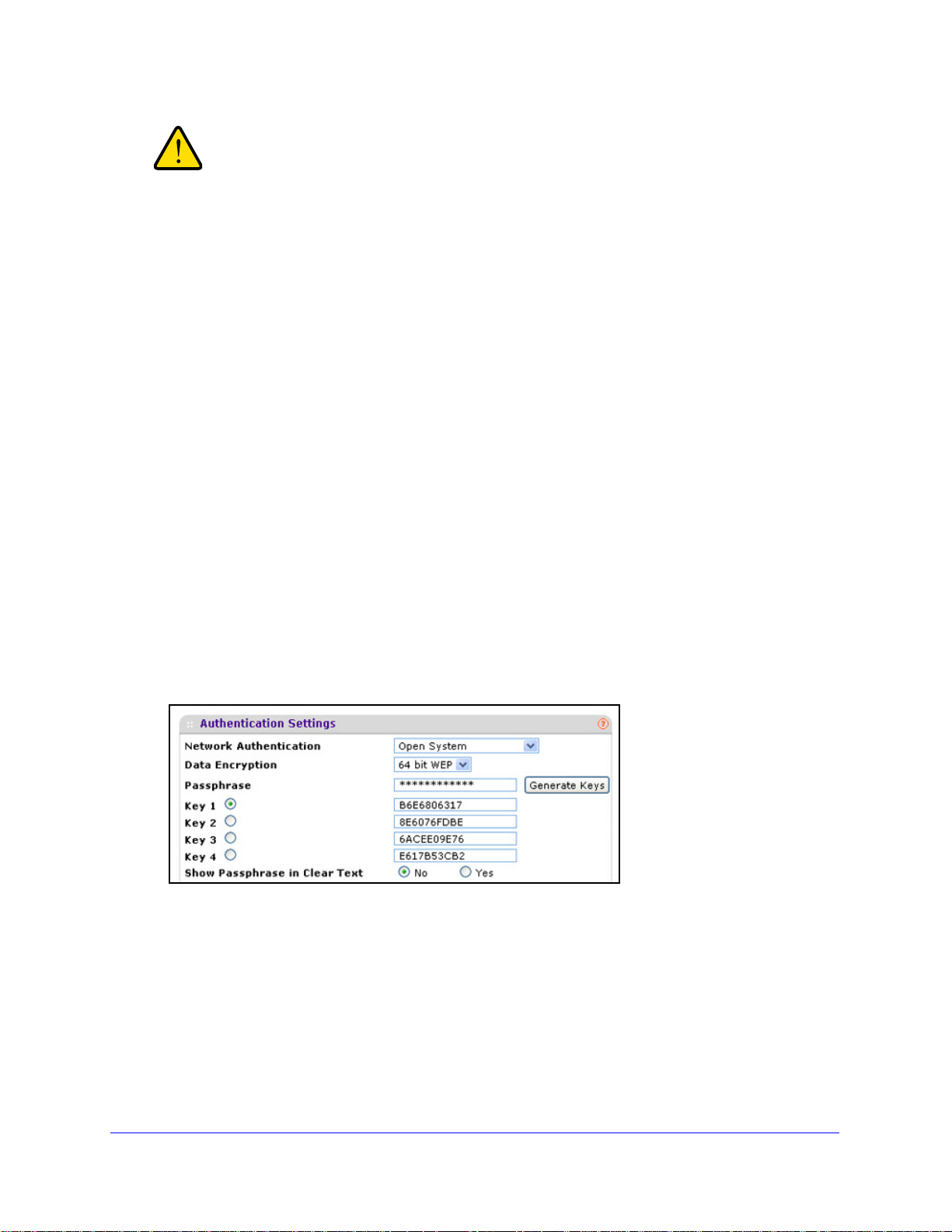
ProSafe Premium 3 x 3 Dual-Band Wireless-N Access Point WNDAP620
WARNING:
If you use a wireless computer to configure wireless security settings,
you are disconnected when you click Apply. Reconfigure your
wireless computer to match the new settings, or access the wireless
access point from a wired computer to make further changes.
To change the QoS policy selection on the Edit Security Profile screen:
1. F
rom the drop-down list from which you want select another QoS policy, select None.
2. Click App
3. Select th
ly to remove the old policy from the security profile.
e new QoS policy from the same drop-down list.
4. Click App
ly to save your settings.
Configure an Open System with WEP or Shared Key with WEP
Whether you use an open system with WEP or shared key with WEP, configure the settings
that are explained in the following table.
• Open system with
An open system can function without any encryption or with pre-shared WEP key
ncryption without RADIUS authentication. The security level of static WEP is not very
e
strong.
When you select Open System from the Network Authentication drop-down list and any
ction other than None from the Data Encryption drop-down list, th e screen expands to
sele
display the WEP fields:
WEP
Figure 21.
• Shared key with WEP
Shared key provides pre-shared WEP key encryption without RADIUS authentication.
he security level of static WEP is not very strong. When you select Shared Key from the
T
Network Authentication drop-down list, the screen expands to display the WEP fields:
Wireless Configuration and Security
53
Page 54

ProSafe Premium 3 x 3 Dual-Band Wireless-N Access Point WNDAP620
Figure 22.
Table 11. WEP encryption settings
Setting Descriptions
Data Encryption Select the encryption key size from the drop-down list:
• 64-b
• 128-bit WEP. Standard WEP encryption, using 104/128-bit encryption.
• 152
it WEP. Standard WEP encryption, using 40/64-bit encryption.
-bit WEP. Proprie tary WEP encryption mode, using 128+24 bit encryption. This
mode functions only with other wireless stations that support this mode.
Passphrase Enter a passphrase. The passphrase length needs to
(inclusive). The secret passphrase allows you to generate the keys automatically by
clicking Generate Keys. The default passphrase is sharedsecret.
You can display the actual passphrase by sele
Yes radio button.
Encryption Key
(Key1–Key4)
Show Passphrase in
Clear Text
Either enter a key manually or allow the key
Generate Keys.
• For ASCII format, depending on the key size selected, the manually entered
encryption
16 characters (152-bit WEP).
• For HEX format, depending on the key size selected, the manually entered or
automatical
26 (128-bit WEP), or 32 (152-bit WEP) characters.
Note: Wireless stations need to use the key
Select the Yes radio button to display the actual passphrase in the Passphrase field. The
default setting is No.
key needs to have a length of 5 (64-bit WEP), 13 (128-bit WEP), or
ly generated encryption key needs to have a length of 10 (64-bit WEP),
to be automatically generated by clicking
to access the wireless access point.
be between 8 and 63 characters
cting the Show Passphrase in Clear Text
Configure Legacy 802.1X
To use legacy 802.1X security, you need to define RADIUS server settings. For information
about RADIUS servers, see Configure RADIUS Server Settings on p
When you select Legacy 802.1X from the Network Authentication drop-down list, the Data
Encryptio
n drop-down list is automatically set to None. To use legacy 802.1X security, you
need to define the RADIUS servers only.
age 57.
Wireless Configuration and Security
54
Page 55
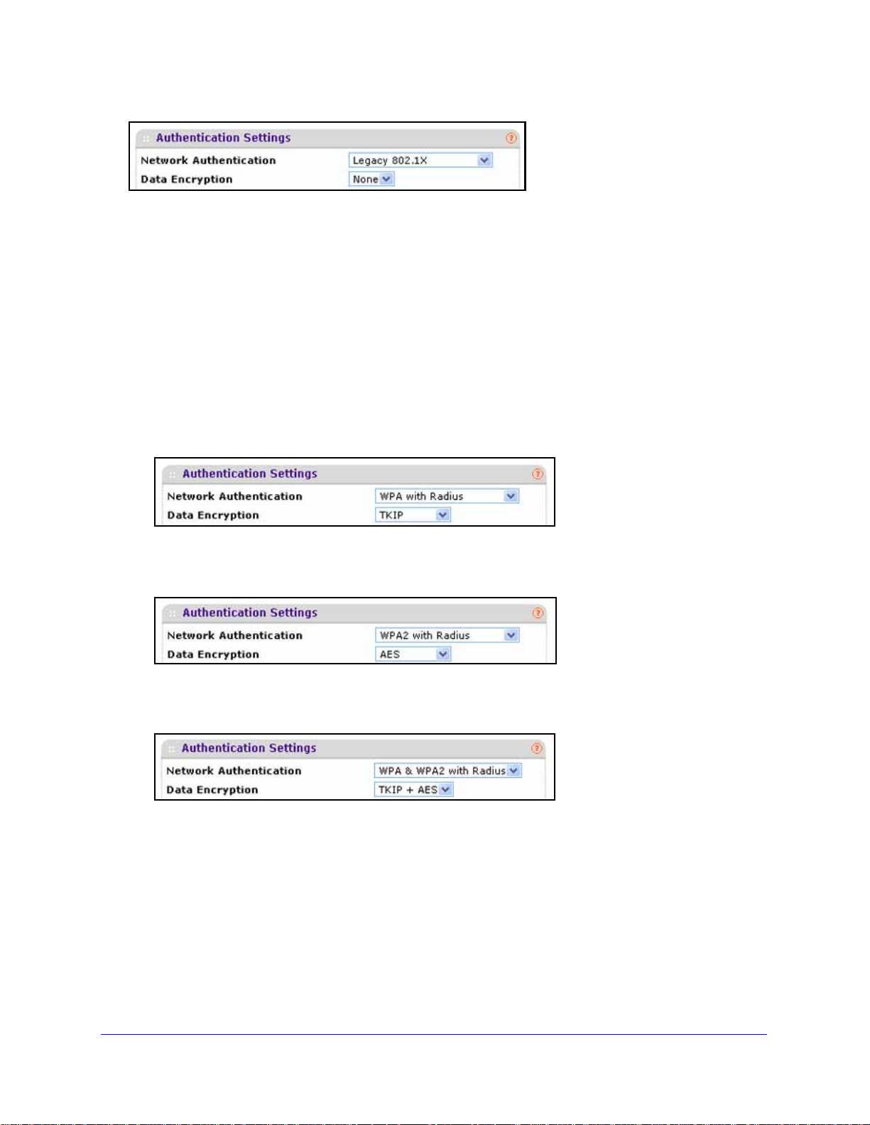
ProSafe Premium 3 x 3 Dual-Band Wireless-N Access Point WNDAP620
Figure 23.
Configure WPA with RADIUS, WPA2 with RADIUS, and WPA & WPA2 with
RADIUS
WPA, WPA2, and WPA & WPA2 security requires RADIUS-based 802.1x authentication, so
you also need to define RADIUS server settings. For information about RADIUS servers, see
Configure RADIUS Server Settings o
n page 57.
The selections that are available from the Da
ta Encryption drop-down list depend on the type
of WP A authentication that you select from the Network Authentication drop-down list and are
shown in the table that follows the figures.
• WP
A with RADIUS
Figure 24.
• WPA2 with RADIUS
Figure 25.
• WPA & WPA2 with RADIUS
Figure 26.
Wireless Configuration and Security
55
Page 56

ProSafe Premium 3 x 3 Dual-Band Wireless-N Access Point WNDAP620
Table 12. Settings for WPA with RADIUS, WPA2
Setting Descriptions
TKIP Temporal Key Integrity Protocol (TKIP) is the standard encryption method used with WPA. You
can also use TKIP with WPA2.
Note: TKIP provides only legacy (slower) rates of op
authentication with AES encryption if you want to use the 11n rates and speed.
AES Advanced Encryption Standard (AES) is the st
Note: Although some wireless clients might support AES with WPA, the WNDAP620 wirel ess
access
TKIP + AES The TKIP + AES encryption method is supported both for WPA and WPA2. Broadcast packets
use TKIP. For unicast (point-to-point) transmissions, WPA clients use TKIP, and WPA2 clients
use AES. For the WPA & WPA2 mixed mode, TKIP + AES is the only supported data encryption
method.
point does not support WPA with AES.
with RADIUS, and WPA & WPA2 with RADIUS
eration. NETGEAR recommends WPA2
andard encryption method used with WPA2.
Configure WPA-PSK, WPA2-PSK, and WPA-PSK & WPA2-PSK
WPA-PSK, WPA-PSK, and WPA-PSK & WPA2-PSK authentication use a pre-shared key
(PSK, also called a passphrase or a network key) and do not require authentication from a
RADIUS server.
The selections that are available from the Dat
a Encryption drop-down list depend on the type
of WPA-PSK authentication that you select from the Network Authentication drop-down list
and are shown in the table that follows the figures.
• WP
A-PSK
Figure 27.
• WPA2-PSK
Figure 28.
Wireless Configuration and Security
56
Page 57

ProSafe Premium 3 x 3 Dual-Band Wireless-N Access Point WNDAP620
• WPA-PSK & WPA2-PSK
Figure 29.
Table 13. Settings for WPA-PSK, WPA2-PSK, and WPA-PSK & WPA2-PSK
Setting Descriptions
Data Encryption TKIP Temporal Key Integrity Protocol (TKIP) is the standard encryption method
used with WPA. You can also use TKIP with WPA2.
Note: TKIP provides only legacy (slower) rates of operation. NETGEAR
recommends
11n rates and speed.
WPA2 authentication with AES encryption if you want to use the
AES Advanced Encryption Standard (AES) is the st
with WPA2.
Note: Although some wireless clients might support AES with WPA, the
WNDAP620 wireless
TKIP + AES TKIP + AES supports both WPA and WPA2. Broadcast packets use TKIP. For
cast (point-to-point) transmissions, WPA clients use TKIP, and WPA2
uni
clients use AES.
For the WPA & WPA2 mixed mode, TKIP
encryption method.
Passphrase Enter a passphrase. The passphrase length needs to be between 8 and 63 characters
clusive). The default passphrase is sharedsecret.
(in
You can display the actual passphrase by selecting the Show Passphrase in Clear Text
s radio button.
Ye
Show Passphrase
r Text
in Clea
Select the Yes radio button to display the actual passphrase in the Passphrase field. The
default setting is No.
access point does not support WPA with AES.
andard encryption method used
+ AES is the only supported data
Configure RADIUS Server Settings
For authentication, accounting, or both authentication and accounting using RADIUS, you
need to configure primary servers and optional secondary servers. These RADIUS server
settings can apply to all devices that are connected to the wireless access point.
You can configure both IPv4 and IPv6 servers. In the IPv4 Radius Server Settings section,
nter IPv4 addresses only; in the IPv6 Radius Server Settings section, enter IPv6 addresses
e
only.
Wireless Configuration and Security
57
Page 58
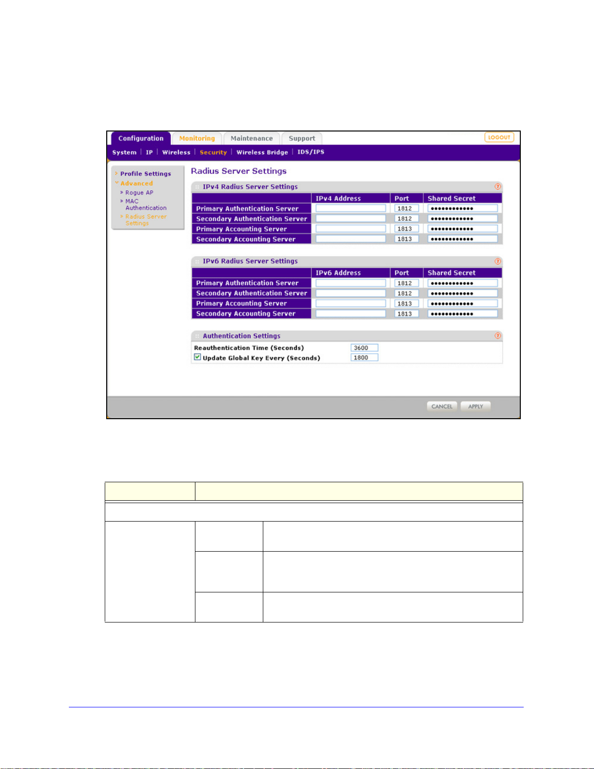
ProSafe Premium 3 x 3 Dual-Band Wireless-N Access Point WNDAP620
To configure the RADIUS server settings:
1. Select Configuration > Security > Advanced > Radius Server Settings. The Radius
Server Settings screen displays.
Figure 30.
2. Specify the settings as explained in the following table:
Table 14. RADIUS server settings for IPv4 and IPv6
Setting Descriptions
Radius Server Settings
Primary
Authentication Server
IPv4 Address or
IPv6 Address
Port Enter the number of the UDP port on the wireless access point
Shared Secret Enter the shared key that is used between the wireless access
Enter the IP address of the primary RADIUS server for
hentication.
aut
hat is used to access the primary RADIUS server for
t
authentication. The default port number is 1812.
int and the primary RADIUS server during authentication.
po
Wireless Configuration and Security
58
Page 59

ProSafe Premium 3 x 3 Dual-Band Wireless-N Access Point WNDAP620
Table 14. RADIUS server settings for IPv4 and IPv6 (continued)
Setting Descriptions
Secondary
Authentication Server
Primary
Accounting Server
Secondary
Accounting Server
IPv4 Address or
IPv6 Address
Port Enter the number of the UDP port on the wireless access point
Shared Secret Enter the shared key that is u
IPv4 Address or
IPv6 Addre
Port Enter the number of the UDP port on the wireless access point
Shared Secret Enter the shared key that is u
IPv4 Address or
IPv6 Addre
Port Enter the number of the UDP port on the wireless access point
Enter the IP address of the secondary RADIUS server for
authentication. The secondary RADIUS server is used when the
primary RADIUS server is not available.
t is used to access the secondary RADIUS server for
tha
authentication. The default port number is 1812.
sed between the wireless access
point and the secondary RADIUS server during authentication.
Enter the IP address of the primary RADIUS server for
ss
accounting.
is used to access the primary RADIUS server for accounting.
that
The default port number is 1813.
sed between the wireless access
point and the primary RADIUS server during the accounting
process.
Enter the IP address of the secondary RADIUS server for
ss
accounting. The secondary RADIUS server is used when the
primary RADIUS server is not available.
t is used to access the secondary RADIUS server for
tha
accounting. The default port number is 1813.
Shared Secret Enter the shared key that is u
Authentication Settings
Reauthentication
ime (Seconds)
T
Update Global Key
ry (Seconds)
Eve
The interval in seconds after which the supplicant is reauthenticated with the
RADIUS server. The default interval is 3600 seconds (1 hour). Enter 0 to disable
reauthentication.
Select the check box to allow the global key update, and enter the interval in
seconds. The check box is selected by default, and the default interval is
1800 seconds (30 minutes). Clear the check box to prevent the global key update.
3. Click Apply to save your settings.
sed between the wireless access
point and the secondary RADIUS server during the accounting
process.
Wireless Configuration and Security
59
Page 60

ProSafe Premium 3 x 3 Dual-Band Wireless-N Access Point WNDAP620
Restrict Wireless Access by MAC Address
For increased security, you can restrict access to an SSID by allowing access to only specific
computers or wireless stations based on their MAC addresses. You can restrict access to
only trusted computers so that unknown computers cannot connect wirelessly to the wireless
access point. MAC address filtering adds an obstacle against unwanted access to your
network, but the data broadcast over the wireless link is fully exposed.
Note: For wireless adapters, you can usually find the MAC address printed
on the wireless adapter.
To restrict access based on MAC addresses:
1. Select Configuration
Authentication screen displays. (The following figure shows some examples.)
Figure 31.
2. Optional: To display the MAC Authent ication screen for the 802.11a/na modes, click the
802.11a/na tab.
3. Select the T
4. From
database options:
• Local
address database for access control. This is the default setting.
urn Access Control On check box to enable the access control feature.
the Select Access Control Database drop-down list, select one of the following
MAC Address Database. The wireless access point uses the local MAC
> Security > Advanced > MAC Authentication. The MAC
• Remote MAC Addres
database on an external RADIUS server on the LAN for access control. If you select
this database, you first need to configure the RADIUS server settings (see Configure
RADIUS Server Settings o
s Database. The wireless access point uses the MAC address
n page 57).
Wireless Configuration and Security
60
Page 61

ProSafe Premium 3 x 3 Dual-Band Wireless-N Access Point WNDAP620
WARNING:
5. Click Refresh to refresh the Available Wireless Stations table. The wir e le s s ac c es s p o in t
places the MAC addresses of the attached wireless stations in this table.
6. Popula
• Select
• Ent
To delete a MAC address from the Trusted Wireless Stations table, sel e c t individ ual c heck
boxes for MAC add
heading, and then click Delete.
7. Click App
Now, only devices in the Trusted Wireless Stations table are allowed to connect to the
wireless a
te the Trusted Wireless Stations table by one of the following methods:
MAC addresses from the Available Wireless Stations table:
a. S
elect individual check boxes for MAC addresses, or select all MAC addresses by
selecting the check box in the heading.
b. Click Move to transfer the MAC a
table to the Trusted Wireless Stations table.
er MAC addresses manually:
a. Ent
b. Click Add.
er a MAC address directly in the Trusted Wireless Stations table.
resses, or select all MAC addresses by selecting the check box in the
ly to save your settings.
ccess point over a wireless connection.
When configuring the wireless access point from a wireless
computer whose MAC address is not on the access control list,
you lose your wireless connection when you click Apply. You then
need to access the wireless access point from a wired computer
or from a wireless computer that is on the access control list to
make any further changes.
ddresses from the Available Wireless Stations
Schedule the Wireless Radio to Be Turned Off
Scheduling the wireless radio to be turned off is a green feature that allows you to turn off the
wireless radio during scheduled vacations, office shutdowns, on evenings, or on weekends.
To schedule the radio to be turned on and off:
1. Select Con
screen displays:
figuration > Wireless > Basic > Wireless On-Off. The Wireless On-Off
Wireless Configuration and Security
61
Page 62
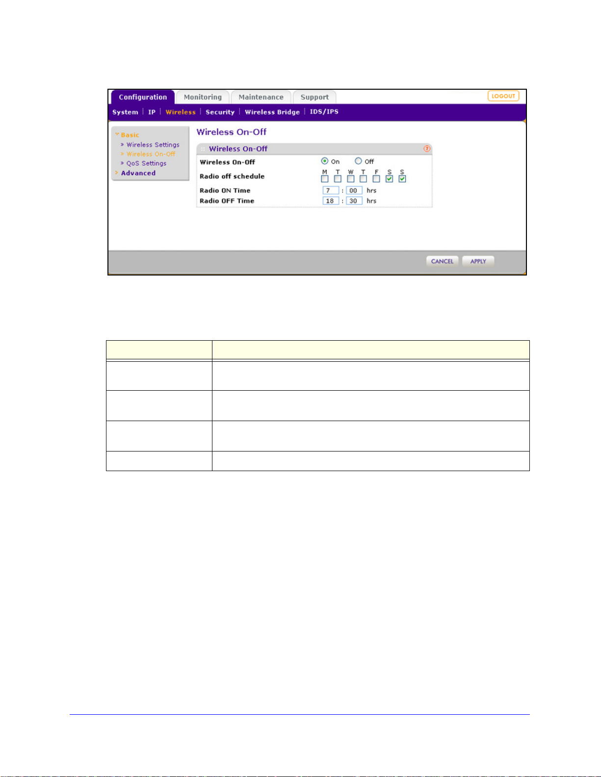
ProSafe Premium 3 x 3 Dual-Band Wireless-N Access Point WNDAP620
Figure 32.
2. Specify the settings as explained in the following table:
Table 15. Wireless radio on/off settings
Setting Description
Wireless On-Off Select the On ra
selected.
Radio off schedule Select check boxes to specify the days when
be turned off. By default, Saturday and Sunday are selected.
Radio ON Time Enter the time that you want the radio to be turned back on. Use 24-hour time
format.
Radio OFF Time Enter the time that you want the radio to be
3. Click Apply to save
your settings.
dio button to enable the timer. By default, the Off radio button is
you want to schedule the radio to
turned off. Use 24-hour time format.
Configure Basic Wireless Quality of Service
Wi-Fi Multimedia (WMM) is a subset of the 802.11e standard. WMM allows wireless traffic to
have a range of priorities, depending on the type of data. Time-dependent information, such
as video or audio, has a higher priority than normal traffic. For WMM to function correctly,
wireless clients also need to support WMM.
By enabling WMM, you allow Quality of Service
from a wireless station to the wireless access point and for downstream traffic flowing from
the wireless access point to a wireless station.
(QoS) control for upstream traffic flowing
WMM defines the following four queues in decreasing or
• Vo
ice. The highest priority queue with minimum delay, which makes it ideal for
applications like VoIP and streaming media.
Wireless Configuration and Security
62
der of priority:
Page 63
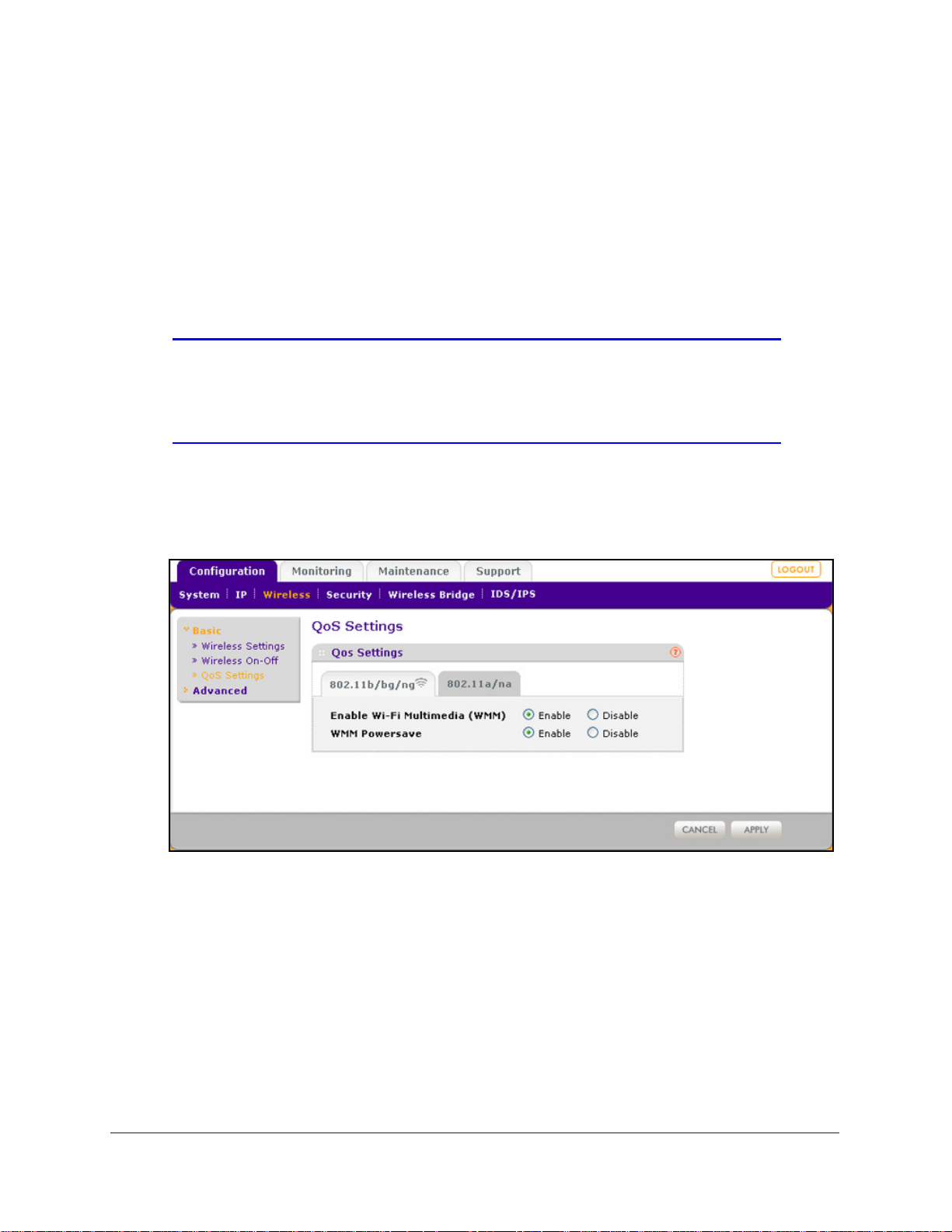
ProSafe Premium 3 x 3 Dual-Band Wireless-N Access Point WNDAP620
• Video. The second highest priority queue with low delay is given to this queue. Video
applications are routed to this queue.
• Best Effort. The medium priority que
ue with medium delay is given to this queue. Most
standard IP applications use this queue.
• Bac
kground. Low priority queue with high throughput. Applications, such as FTP, that
are not time-sensitive but require high throughput can use this queue.
The WMM Powersave feature saves power for ba
efficiency and flexibility of data transmission.
Note: For information about how to configure advanced wireless QoS, that
is, to configure specific Enhanced Distributed Channel Access
(EDCA) settings, see
Configure Advanced Quality of Service
Settings on page 110.
To configure basic wireless QoS:
1. Select Con
figuration > Wireless > Basic > QoS Settings. The basic QoS Settings
screen displays:
ttery-powered equipment by increasing the
Figure 33.
2. Optional: To display the basic QoS S et t in gs screen for the 802.11a/na modes, click the
802.11a/na tab.
3. Enable
• Ena
or disable the WMM features:
ble Wi-Fi Multimedia (WMM). To enable this feature, select the Enable radio
button, which is the default setting. Select the Disable radio button to disable the
feature.
• W
MM Powersave. To enable this feature, select the Enable radio button, which is the
default setting. Select the Disable radio button to disable the feature.
4. Click App
ly to save your settings.
Wireless Configuration and Security
63
Page 64

4. Management and Monitoring
This chapter describes how to use the management and monitoring features of the wireless
access point. The chapter includes the following sections:
• Enable Remote Management
• Upgrade the Wireless Access Point Software
• Manage the Configuration File or Reset to Factory Defaults
• Change the Administrator Password
• Manage User Accounts
• Enable the Syslog Server
• Monitor the Wireless Access Point
• Enable Rogue AP Detection and Monitor Access Points
• Configure Wireless Intrusion Detection and Prevention
4
Enable Remote Management
• SNMP Management
• Secure Shell and Telnet Management
Both Simple Network Management Protocol (SNMP) and the remote console Secure Shell
(SSH) are
point from a client running SNMP management software, as well as from an SSH client. The
Telnet console is disabled by default.
SNMP Management
To set up an SNMP management interface:
1. Se
enabled by default, which allows for remote management of the wireless access
lect Maintenance > Remote Management > SNMP. The SNMP screen displays:
64
Page 65

ProSafe Premium 3 x 3 Dual-Band Wireless-N Access Point WNDAP620
Figure 34.
2. Spe cify the settings as explained in the following table:
Table 16. SNMP settings
Setting Description
SNMP Select the Enable radio button to allow the SNMP network management
software, such as HP OpenView, to manage the wireless access point
through SNMPv1/v2 protocol. By default, the Disable radio button is
selected.
Read-Only Community Name Enter the community string to allow the
wireless access point’s Management Information Base (MIB) objects. The
default is public.
Read-Write Community Name Enter the community string to allow the SNMP manager to read and write
e wireless access point’s MIB objects. The default is private.
th
Trap Community Name Enter the community string to allow the SNMP
default is trap.
IP Address to Receive Traps Enter the IP address of the SNMP manager to receive traps sent from the
wireless ac
Trap Port Enter the number of the SNMP manager port to receive
wireless access point. The default is 162.
3. Click App
ly to save your settings.
cess point.
SNMP manager to read the
manager to send traps. The
traps sent from the
Management and Monitoring
65
Page 66
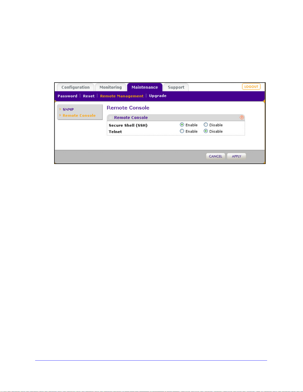
ProSafe Premium 3 x 3 Dual-Band Wireless-N Access Point WNDAP620
Secure Shell and Telnet Management
To configure remote console features:
1. Select Ma
intenance > Remote Management > Remote Console. The Remote
Console screen displays:
Figure 35.
2. Enable or disable the remote console features:
• Secure Shell
(SSH). To enable this feature, select the Enable radio button, which is
the default setting. Select the Disable button to disable the feature.
• T
elnet. To enable this feature, select the Enable radio button. Select the Disable
button to disable the feature, which is the default setting.
3. Click Apply to save
To manage the wireless access point over a Telnet connection:
1. Connect an Ethern
2. Connect th
e other end of the cable to a VT100/ANSI terminal or a workstation.
If you attach a PC, Apple Macintosh, or UNIX
your settings.
et cable to the console port of the wireless access point.
workstation, start a secure terminal
emulation program, and configure the terminal emulation program to use the following
settings:
• Baud ra
• Dat
• Parity: non
• S
top bit: 1
• Flow control: non
3. S
tart a secure Telnet session from the terminal or workstation to the wireless access point. A
te: 9600 bps
a bits: 8
e
e
screen similar to the following displays:
Management and Monitoring
66
Page 67
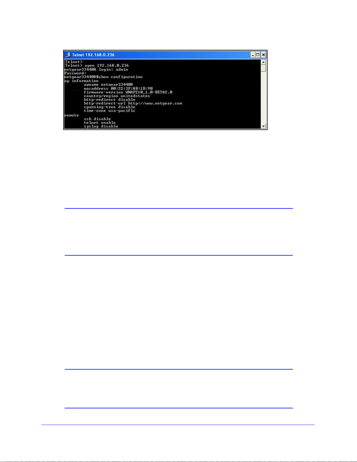
ProSafe Premium 3 x 3 Dual-Band Wireless-N Access Point WNDAP620
Figure 36.
4. Enter the login name and password (admin and password are the defaults).
After successful login, the > prompt ap
access point. In this example, the prompt is netgear334408.
5. Ente
r the CLI commands that you want to use. You can enter show configuration to
display the available CLI commands. The CLI commands are also listed in Appendix B,
Command-Line Reference.
Note: You can also access the wireless access point remotely over a
Telnet or SSH session using an application such as PuTTY, if such
an encryption application is allowed by law in your country. After you
have connected to the wireless access point, enter the login name
and password to access the CLI.
pears, preceded by the name of the wireless
Upgrade the Wireless Access Point Software
The software of the wireless access point is stored in flash memory and can be upgraded as
NETGEAR releases new software. You can download upgrade files from the NETGEAR
website. If the upgrade file is compressed (.zip file), you first need to extract the image (.rmt)
file before sending it to the wireless access point. You can send the upgrade file using your
browser. There are two methods to perform a software upgrade that are described in the
following sections:
• Web Browser Upgrade Procedure
• TFTP Server Upgrade Procedure
Note: The web browser that you use to upload new firmware into the
wireless access point needs to support HTTP uploads. Use a
browser such as Microsoft Internet Explorer 6.0 or later or Mozilla
1.5 or later.
Management and Monitoring
67
Page 68

ProSafe Premium 3 x 3 Dual-Band Wireless-N Access Point WNDAP620
WARNING:
IMPORTANT:
Note: You cannot perform the software upgrade from a computer that is
connected to the wireless access point over a wireless link. You
need to use a computer that is connected to the wireless access
point over an Ethernet cable.
When uploading software to the wireless access point, do not
interrupt the web browser by closing the window, clicking a link, or
loading a new page. If the browser is interrupted, the upload might
fail, corrupt the software, and render the wireless access point
inoperable.
In some cases, such as a major upgrade, you might need to erase the
configuration and manually reconfigure your wireless access point
after upgrading it. See the release notes included with th e software to
find out if you need to reconfigure the wireless access point.
Web Browser Upgrade Procedure
To use a web browser to upgrade the wireless access point firmware:
1. Downloa
disk.
2. If
necessary, unzip the ne w so ftw are fil e.
3. If
available, read the release notes before upgrading the software.
4. Select Maintenance
displays:
d the new software file from the NETGEAR website and save it to your hard
> Upgrade > Firmware Upgrade. The Firmware Upgrade screen
Figure 37.
Management and Monitoring
68
Page 69

ProSafe Premium 3 x 3 Dual-Band Wireless-N Access Point WNDAP620
5. Click Browse and locate the image (.zip) upgrade file.
6. Click App
During the upgrade process, the wireless access point auto
ly to initiate the upgrade process.
matically restarts. The
upgrade process typically takes several minutes. When the Test LED turns off, wait a few
more seconds before doing anything with the wireless access point.
erify that the new software file has been installed by selecting Monitorin g > System. The
7. V
System screen displays (see Figure 46 on p
age 78). The firmware version is shown in the
Access Point Information section of the screen.
TFTP Server Upgrade Procedure
To use this method, you need to have a TFTP server set up.
To use a TFTP server to upgrade the wireless access point firmware:
1. Download th
disk.
2. Place the sof
3. If available,
4. Select Main
screen displays:
e new software file from the NETGEAR website and save it to your hard
tware file in your TFTP server location. (You do not need to unzip the file.)
read the release notes before upgrading the software.
tenance > Upgrade > Firmware Upgrade TFTP. The Firmware Upgrade TFTP
Figure 38.
5. Specify the following information:
• F
irmware File Name. The name of the unzipped software file.
• T
FTP Server IP. The IP address of your TFTP server.
6. Click App
During the upgrade process, the wireless access point auto
ly to initiate the upgrade process.
matically restarts. The
upgrade process typically takes several minutes. When the Test LED turns off, wait a few
more seconds before doing anything with the wireless access point.
Management and Monitoring
69
Page 70
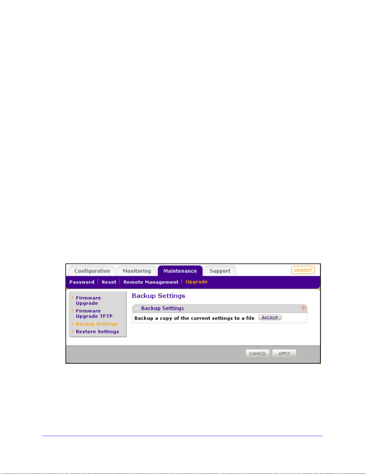
ProSafe Premium 3 x 3 Dual-Band Wireless-N Access Point WNDAP620
7. Verify that the new software file has been installed by selecting Monitoring > System. The
System screen displays (see Figure 46 on p
Access Point Information section of the screen.
age 78). The firmware version is shown in the
Manage the Configuration File or Reset to Factory Defaults
• Save the Configuration
• Restore the Configuration
• Restore the Wireless Access Point to the Factory Default Settings
• Reboot the Wireless Access Point without Re
The wireless access point settings are stored in the
(back it up) to a computer, restore it from a computer, or reset it to factory default settings.
storing the Default Configuration
configuration file. You can save this file
Save the Configuration
To save your settings:
1. Select M
displays (see the following figure).
2. Click Backup. Y
wir el es s a c ce ss po i nt and prompts you for a location on your computer to store the file.
3. Fo
aintenance > Upgrade > Backup Settings. The Backup Settings screen
our browser extracts the configuration file (the file name is config) from the
llow the instructions of your browser to save the file.
Figure 39.
Management and Monitoring
70
Page 71

ProSafe Premium 3 x 3 Dual-Band Wireless-N Access Point WNDAP620
IMPORTANT:
Restore the Configuration
During the restoration process, do not try to go online, turn off the
wireless access point, shut down the computer , or do anything else
to the wireless access point until it finishes restarting!
To restore your settings from a saved configuration file:
1. Select M
displays:
Figure 40.
2. Click Browse and locate the backup configuration file (the file name is config).
3. Click App
access point automatically restarts. The restoration process typically takes about 1 minute.
When the Test LED turns off, wait a few more seconds before doing anything with the
wireless access point.
aintenance > Upgrade > Restore Settings. The Restore Settings screen
ly to initiate the restoration process. During the restoration process, the wireless
Restore the Wireless Access Point to the Factory Default Settings
You can restore the wireless access point to the factory default settings by two methods that
are described in the following sections:
• Use the Web Management Interface to Restore Factory Default Settings
• Use the Reset Button to Restore Factory Default Settings
Management and Monitoring
71
Page 72

ProSafe Premium 3 x 3 Dual-Band Wireless-N Access Point WNDAP620
IMPORTANT:
Note: After you have restored the factory default settings on the wireless
access point:
* All custo
* The login
* The de
* The DHCP
* The Access Point Name
m configurations are lost.
password is password.
fault LAN IP address is 192.168.0.100.
client is disabled.
field is reset to the name printed on
the label on the bottom of the unit.
Use the Web Management Interface to Restore Factory Default Settings
During the restoration process, do not try to go online, turn off the
wireless access point, shut down the computer , or do anything else
to the wireless access point until it finishes restarting!
To restore the factory default settings using the web management interface:
1. Select Ma
intenance > Reset > Restore Defaults. The Restore Defaults screen
displays:
Figure 41.
2. Select the Yes radio button. (By default, the No radio button is selected.)
3. Click Apply
During the restoration process, the wireless access point au
to reset the w ir e le ss ac c es s p oi n t to the factory default settings.
tomatically restarts. The
restoration process typically takes about 1 minute. When the Test LED turns off, wait a
few more seconds before doing anything with the wireless access point.
Management and Monitoring
72
Page 73

ProSafe Premium 3 x 3 Dual-Band Wireless-N Access Point WNDAP620
Use the Reset Button to Restore Factory Default Settings
To restore the factory default settings when you do not know the login user name, login
password, or IP address, you need to use the Reset button on the rear panel of the wireless
access point (see Figure 2 on
To restore the factory default settings using the Reset button:
page 13).
1. Using a sharp obje
LED b li n ks ra pi d ly ) to reset the wireless access point to factory def aults settings.
Note: Pressing the Reset button for a shorter time simply causes the
wireless access point to reboot.
2. Release the Reset button.
During the restoration process, the wireless a
restoration process typically takes about 1 minute. When the Test LED turns off, wait a
few more seconds before doing anything with the wireless access point.
ct, press and hold the Reset button for about 5 seconds (un ti l t he Test
ccess point automatically restarts. The
Reboot the Wireless Access Point without Restoring the Default Configuration
If you do not have physical access to the wireless access point to switch it off and on again,
you can use the software to reboot the wireless access point.
To reboot the wireless access point:
1. Select Mainte
nance > Reset > Reboot AP. The Reboot AP screen displays:
Figure 42.
2. Select the Yes radio but ton. (By default, the No radio button is selected.)
3. Click App
ly to reboot the w i re l es s a cc e ss po in t .
Management and Monitoring
73
Page 74
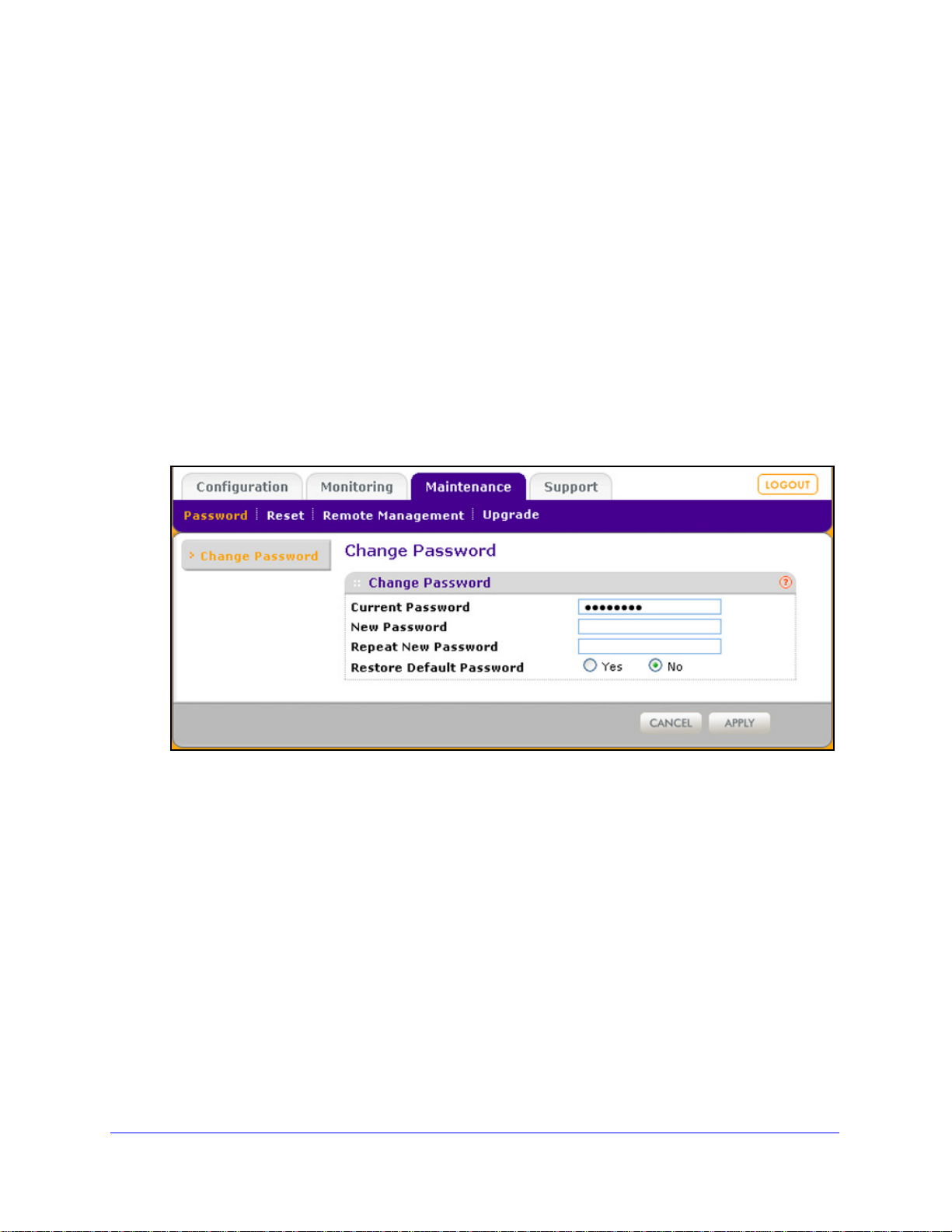
ProSafe Premium 3 x 3 Dual-Band Wireless-N Access Point WNDAP620
The reboot process typically takes about 1 minute. When the Test LED turns off, wait a
few more seconds before doing anything with the wireless access point.
Change the Administrator Password
The default password is password. NETGEAR recommends that you change this password
to a more secure password. You cannot change the administrator login name (admin).
The ideal password contains no dictio
letters (both uppercase and lowercase), numbers, and symbols. Your password can be up to
30 characters.
To change the administrator password:
1. Select Ma
displays:
intenance > Password > Change Password. The Change Password screen
nary words from any language and is a mixture of
Figure 43.
2. Take one of the following actions:
• Enter a
New Password field.
• Next t
password. By default, the No radio button is selected.
3. Click Apply to save
If you have restored the default password, the login password is p
configured a new password, write it down in a secure place.
new password twice, once in the New Password field and again in the Repeat
o Restore Default Password, select the Yes radio button to restore the default
your settings.
Management and Monitoring
74
assword. If you have
Page 75
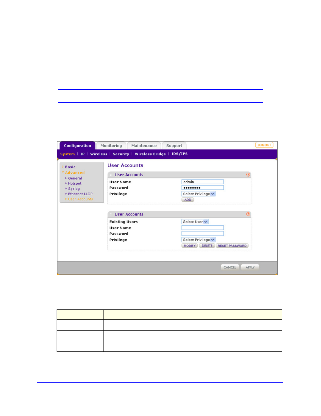
ProSafe Premium 3 x 3 Dual-Band Wireless-N Access Point WNDAP620
Manage User Accounts
The admin user account is the default user account, which you cannot delete. However, you
can add other user accounts, modify them, and delete them. Users for whom you set up an
account can access the web management interface with read-only or read-write privileges.
Note: Only the administrator can create, change, and delete user accounts.
To add a new user account:
1. Select Con
screen displays:
figuration > System > Advanced > User Accounts. The User Accounts
Figure 44.
2. Configure the settings in the upper part of the screen as explained in the following table:
Table 17. Add user account settings
Setting Description
User Name Enter a new user name
Password Enter a password between 4 and 12 characters in length.
Privilege From the Privilege drop-down list, select Read
Write or Read Only.
3. Click Add.
4. Click App
ly to save your settings.
Management and Monitoring
75
Page 76

ProSafe Premium 3 x 3 Dual-Band Wireless-N Access Point WNDAP620
To change the name for a user account:
1. On the User Accounts screen, in the lower part of the screen, select the user from the
Existing Users drop-down list.
the User Name field, modify the name.
2. In
3. Click Modi
4. Click Apply to save
To change the privilege for a user account:
fy .
your settings.
1. On
the User Accounts screen, in the lower part of the screen, select the user from the
Existing Users drop-down list.
2. From
3. Click Reset Password. The p
4. Click Apply to save
To reset the password for a user account:
1. On
the Privilege drop-down list, select another privilege.
assword is reset to the default password, which is password.
your settings.
the User Accounts screen, in the lower part of the screen, select the user from the
Existing Users drop-down list.
2. Click Reset Password. The p
3. Click Apply to save
your settings.
assword is reset to the default password, which is password.
Note: If you want to modify a password, delete the user account, and then
recreate the user account with the password of your choice.
To delete a user account:
1. On
the User Accounts screen, in the lower part of the screen, select the user from the
Existing Users drop-down list.
2. Click Delete.
3. Click Apply to save
your settings.
Enable the Syslog Server
The Syslog screen allows you to enable the syslog option if you have a syslog server on your
LAN. If syslog is enabled, the wireless access point sends its syslog files to the syslog server.
To enable a syslog server:
1. Select Configuration
> System > Advanced > Syslog. The Syslog screen displays:
Management and Monitoring
76
Page 77
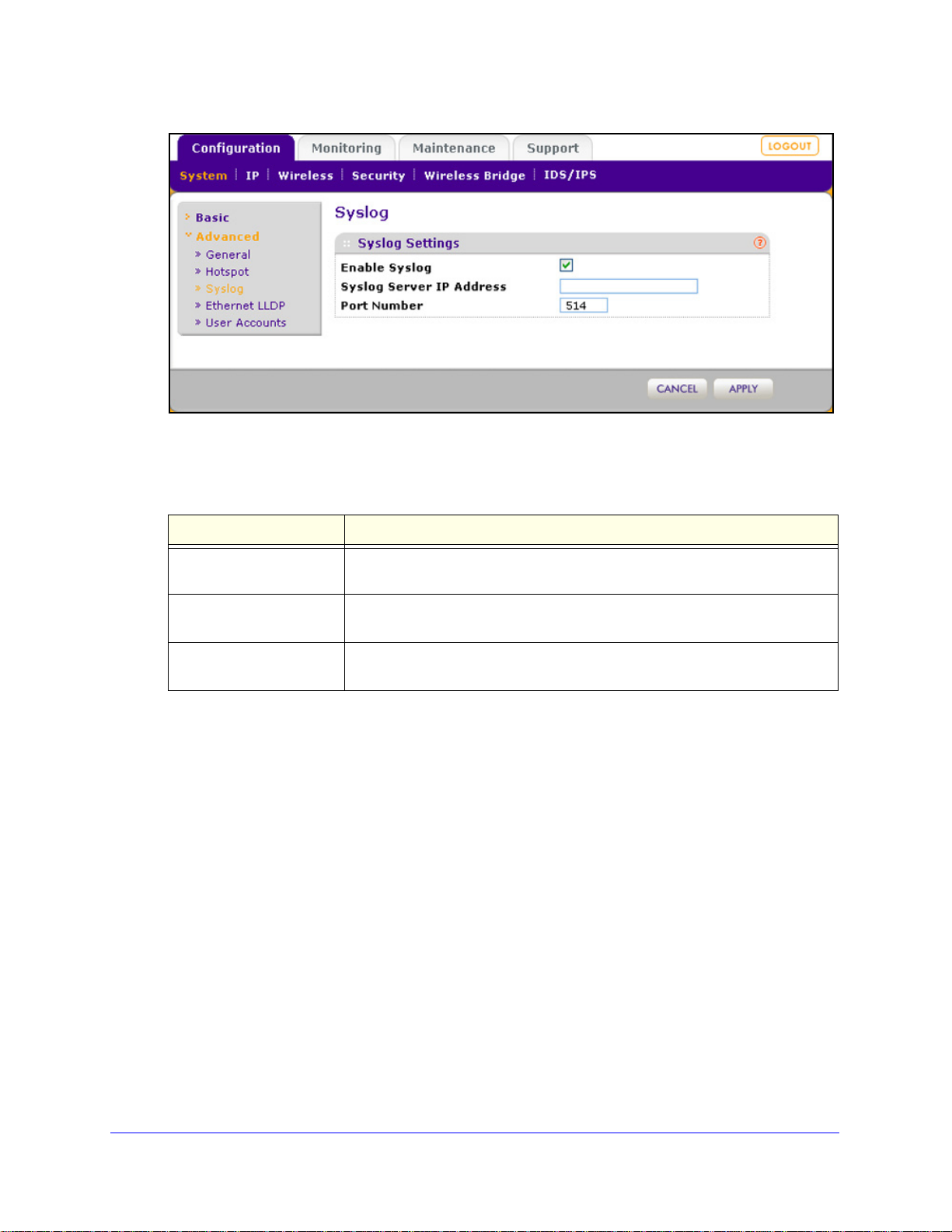
ProSafe Premium 3 x 3 Dual-Band Wireless-N Access Point WNDAP620
Figure 45.
Specify the settings as explained in the following table:
Table 18. Syslog settings
Setting Description
Enable Syslog Select the check box to enable the syslog option. By default, the syslog option
is disabled.
Syslog Server IP Address Enter the IP address of the syslog
sends the syslog files.
Port Number Enter the port number that is
number is 514.
2. Click App
ly to save your settings.
Monitor the Wireless Access Point
• View System Information
• Monitor Wireless Stations
• View the Activity Log
• Traffic Statistics
server to which the wireless access point
configured on the syslog server. The default port
View System Information
The System screen provides a summary of the current wireless access point configuration
settings, including current IP settings and current wireless settings. This information is read
only, so any changes need to be made on other screens.
Management and Monitoring
77
Page 78
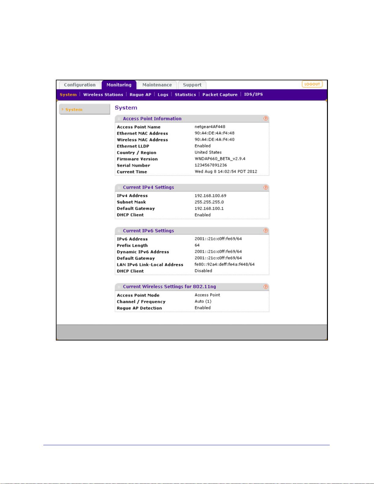
ProSafe Premium 3 x 3 Dual-Band Wireless-N Access Point WNDAP620
To view the System screen:
Select Monitoring > System.
Figure 46.
Management and Monitoring
78
Page 79

ProSafe Premium 3 x 3 Dual-Band Wireless-N Access Point WNDAP620
The following table explains the fields of the System screen:
Table 19. System screen field s
Setting Description
Access Point Information
Access Point Name The NetBIOS name. For information about how to change the default name, see
Configure Basic General System Settings and Time Settings o
Ethernet MAC Address The MAC address of the wireless access point’s Ethernet port.
Wireless MAC Address The MAC address of the wireless access point’s wireless card.
Ethernet LLDP Enabled indicates that LLDP is enabled. Disabled indicates that it is not.
n page 23.
Country/Region The country or region for which the wireless a
information about how to change the country or region, see Configure Basic General
System Settings and Time Settings on
Note: It might not be legal to operate this wireless access point in a country or region
er than one of those identified in this field.
oth
Firmware Version The version of the firmware that is currently installed.
Serial Number The serial number of the wireless access point.
Current Time The current time. For information
Configure Basic General System Settings and Time Settings on page 23.
Current IPv4 Settings
For information about how to change any of these IP settings, see Configure the IPv4 Settings o
IP Address The IPv4 address of the wireless access point.
Subnet Mask The subnet mask for the address of
Default Gateway The default IPv4 gateway for the wireless access point communication.
DHCP Client Enabled indicates that the current IP address was obtained from a DHCPv4 server on
ur LAN network. Disabled indicates a static IP configuration.
yo
Current IPv6 Settings
For information about how to change any of these IP settings, see Configure IPv6 Settings and Optional
DHCPv6 Server Settings o
n page 99.
about how to change the time settings, see
the wireless access point.
ccess point is licensed for use. For
page 23.
n page 25.
IPv6 Address The default IPv6 address of the wireless
Prefix Length The prefix length for the address of the wireless access point.
Dynamic IPv6 Address The dynamically assigned IPbv6 address if the DHCPv6 server has the stateful
option
enabled.
Default Gateway The default IPv6 gateway for the wireless access point communication.
LAN IPv6 Link-Local
dress
Ad
This is an automatically generated IPv6 address that uses the IPv4 address in the
interface portion of its address.
access point.
Management and Monitoring
79
Page 80

ProSafe Premium 3 x 3 Dual-Band Wireless-N Access Point WNDAP620
Table 19. System screen fields (continued)
Setting Description
DHCP Client Enabled indicates that the current IP address was obtained from a DHCPv6 server on
your LAN network. Disabled indicates a static IP configuration.
Current Wireless Settings for 802.11b, 802
or
Current Wireless Settings for 802.11a or 802.1
Note: The section heading depends on the configured wireless mode.
Access Point Mode The operating mode of the wireless access point. One of the following modes is
dicated:
in
• Access Point
• Point-to-Point Bridge
• Point-to-Point Bridge with Access Point
• Multi-Point Bridge with/without cl
For information about how to change the mode, see Configure Wireless Bridging on
page 118.
Channel / Frequency The channel that the wireless port is using
channel and frequency, see Configure 802.11b/bg/ng Wireless Settings on p
and Configure 802.11a/na Wireless Settings on page 31.
Rogue AP Detection Enabled indicates that rogue AP detecti on is enabled. Disabled indicates that it is not.
.11g, or 802.11ng
1na
ient association
. For information about how to change the
age 28
Monitor Wireless Stations
The Wireless St ations screen contains the Ava ilable Wireless S tations table. This t able shows
all IP devices that are associated with the wireless access point in the wireless network that
is defined by the wireless network name (SSID). The table heading indicates the wireless
mode (802.11b, 802.11bg, or 802.11ng for the 2.4-GHz band, or 802.11a or 802.11na for the
5-GHz band).
Note: A wireless network can include multiple wireless access points, all
using the same network name (SSID). This uniformity extends the
reach of the wireless network and allows users to roam from one
wireless access point to another, providing seamless network
connectivity. Under these circumstances, be aware that the
Available Wireless Stations table includes only the stations
associated with this wireless access point.
To view the attached wireless stations, and to view details for a wireless station:
1. Select Mon
itoring > Wireless Stations. The Wireless Stations screen displays:
Management and Monitoring
80
Page 81
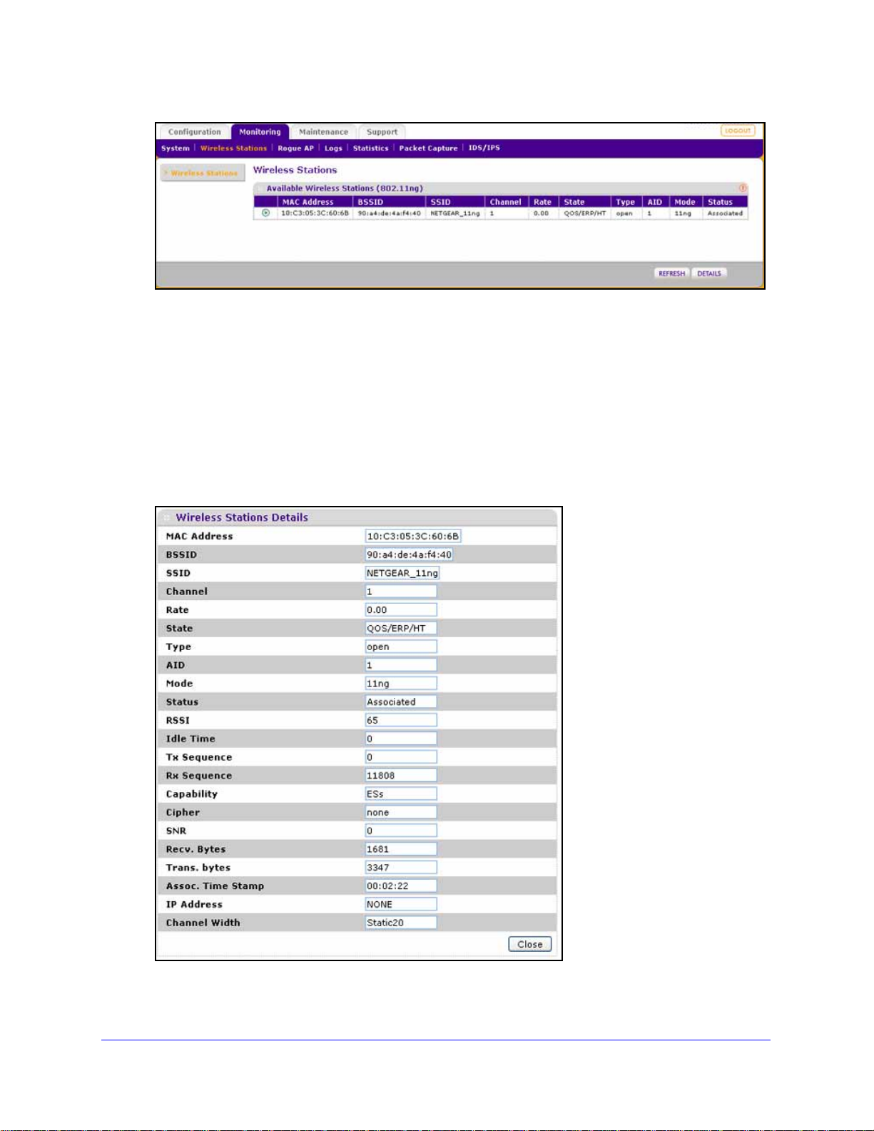
ProSafe Premium 3 x 3 Dual-Band Wireless-N Access Point WNDAP620
Figure 47.
To update the list, click Refresh. If the wireless access point is rebooted, the wireless
station data is lost until the wireless access point rediscovers the devices. To force the
wireless access point to look for associated devices, click Refresh.
The Available Wireless Stations table shows the MAC address, BSSID, SS
ID, channel,
rate, state, type, AID, mode, and status for each device. For information about these and
more fields, see the table that follows the next figure.
2. T
o view details of a wireless station, select the corresponding radio button, and then click
Details. The Wireless Stations Details screen displays:
Figure 48.
Management and Monitoring
81
Page 82

ProSafe Premium 3 x 3 Dual-Band Wireless-N Access Point WNDAP620
The following table explains the fields of the Wireless Stations Details screen:
Table 20. Wireless stations details fields
Setting Description
MAC Address The MAC address of the wireless station.
BSSID The BSSID that the wireless
SSID The SSID that the wireless station is using.
Channel The channel that the wireless station is using.
Rate The transmit data rate in Mbps of the wireless station.
State The features that are enabled on the wireless station.
Type The authentication and encryption type th
AID The associated identifier (AID) of the wireless station.
Mode The wireless mode in which the
Status The wireless status of the wireless station (Associated).
RSSI The received signal strength indicator (RSSI) of the wireless station.
Idle Time The time since the last frame was received from the wireless station.
Tx Sequence The sequence number of the last frame that wa
Rx Sequence The sequence number of the last frame that was received from the wireless station.
Capability The summary of the capability of the wirele
association.
station is using.
at the wireless station is using.
wireless station is operating.
s transmitted to the wireless station.
ss station that was detected during
Cipher The cipher that the wireless station is using and that defines the type of encryption.
SNR The signal-to-noise ratio (SNR) that indicates how much the signal of the wireless
ation has been corrupted by noise.
st
Recv. Bytes The number of bytes received on the wireless st
Trans. bytes The number of bytes transmitted by the w
Assoc. Time S tamp The time when these details of the wireless station were retrieved.
IP Address The IP address of the wireless station.
Channel Width The channel width at which the
wireless station operates.
ation since it last started up.
ireless station since it last started up.
Management and Monitoring
82
Page 83

ProSafe Premium 3 x 3 Dual-Band Wireless-N Access Point WNDAP620
View the Activity Log
You can view the wireless access point’s activity logs onscreen and save the logs.
To display the activity log and save it:
1. Select Monitoring
Figure 49.
2. Click Save As to save the log contents to a file on your computer or t o a disk drive.
> Logs. The Logs screen displays:
To update the display onscreen, click Refresh; to clear t
he log content, click Clear.
Traffic Statistics
The St atistics screen disp lays information for both wire d (LAN) and wireless (WLAN) network
traffic.
To display the Statistics screen:
Select Monit
oring > Statistics.
Management and Monitoring
83
Page 84

ProSafe Premium 3 x 3 Dual-Band Wireless-N Access Point WNDAP620
Figure 50.
To update the statistics information, click Refresh.
The following table explains the fields of the
Table 21. Statistics fields
Setting Description
Wired Ethernet
Packets The number of packets received and transmitted over the Ethernet connection
since the wireless access point was restarted.
Bytes The number of bytes received and transmitte
since the wireless access point was restarted.
Wireless 802.11b, W
Note: The section heading depends on the configured wireless mode.
Unicast Packets The number of unicast packets received and transmitted over the wireless
ireless 802.11bg, Wireless 801.11ng, Wireless 802.11a, or Wireless 802.11na
nection since the wireless access point was restarted.
con
Statistics screen:
d over the Ethernet connection
Management and Monitoring
84
Page 85

ProSafe Premium 3 x 3 Dual-Band Wireless-N Access Point WNDAP620
Table 21. Statistics fields (continued)
Setting Description
Broadcast Packets The number of broadcast packets received and transmitted over the wireless
connection since the wireless access point was restarted.
Multicast Packets The number of multicast packets received and transmitted over the wireless
ction since the wireless access point was restarted.
conne
Total Packets The total number of packets received and transmitted over the wireless
connection since the wireless access point was restarted.
Total Bytes The total number of bytes received and transmitted over the wireless connection
ess access point was restarted.
Client Association
802.11b Radio,
802.11bg Radio, or
802.11ng Radio
802.11na Radio or
802.11a Radio
since the wirel
The number of associated clients connected to the radio in the configured
wireless modes.
Enable Rogue AP Detection and Monitor Access Points
• Enable and Configure Rogue AP Detection
• View and Save Access Point Lists
Enable and Configure Rogue AP Detection
The wireless access point can detect rogue access point s and prevent them from connecting
to the wireless access point. The wireless access point maintains a list of access points it
detects in the area. Initially all detected access points are displayed in the Unknown AP List.
You restrict communication to approved access points by adding them to the Known AP List
and enabling the rogue AP detection feature.
If you enable rogue AP detection, the wireless access point continuously scans the wireless
etwork and collects information about all access points on its channel.
n
To enable and configure rogue AP detection:
1. Select Con
displays. (The following figure shows examples in the Known AP List and Unknown AP
List.)
figuration > Security > Advanced > Rogue AP. The Rogue AP screen
Management and Monitoring
85
Page 86

ProSafe Premium 3 x 3 Dual-Band Wireless-N Access Point WNDAP620
Figure 51.
2. Optional: To enable and configure rogu e AP detection for the 802.11a/na modes, click the
802.11a/na tab.
3. Select the T
pecify the detection policy by making a selection from the Rogue AP Detection Policy
4. S
urn Rogue AP Detection On check box to enable rogue AP dete ction.
drop-down list:
• Mild. The wireless acce
• Mod
erate. The wireless access point scans for rogue access points e very 5 seconds.
ss point scans for rogue access points every 10 seconds.
This is the default setting.
• Aggressive. The wireless acce
5. Click Refresh to let the
wireless access point discover the access points and populate the
ss point scans for rogue access points every second.
Unknown AP List.
6. In
the Unknown AP List, select individual check boxes for access points, or select all access
points by selecting the check box in the column heading.
7. Click Move to
8. Click Apply to save
To remove APs from the Known AP List and return them to the Unknown AP List:
1. In the Kno
transfer the access points from the Unknown AP List to the Known AP List.
your settings.
wn AP List, select individual check boxes for access points, or select all
access points by selecting the check box in the column heading.
2. Click Delete.
To import a file with a precompiled list of access points into the Known AP List:
ake one of the following actions:
1. T
• Select the
Replace radio button to let the imported list of access points replace the
existing Known AP List.
Management and Monitoring
86
Page 87

ProSafe Premium 3 x 3 Dual-Band Wireless-N Access Point WNDAP620
• Select the Merge radio button to add the imported list of access points to the existing
Known AP List.
2. Click Br
owse and locate the file that contains the list of access points. This file needs to be
a simple text file with one MAC address per line.
3. Select th
4. Click App
e file, and click Open.
ly to upload the lis t o f ac c es s p o in ts to the Known AP List.
View and Save Access Point Lists
The wireless access point detects nearby APs and wireless st ations and maint ains them in a
list. You can use this list to prevent them from connecting to the wireless access point.
To view the Unknown AP List and save it to a file:
1. Select Monitoring
displays:
> Rogue AP > Unknown AP List. The Unknown AP List screen
Figure 52.
2. Click Refresh to let the wireless access point discover the access points and populate the
Unknown AP List for the configured wireless mode.
The following table explains the fields of the Unknown AP List screen:
Table 22. Unknown AP List fiel ds
Setting Description
MAC Address The MAC address of the unknown AP.
SSID The SSID that the unknown AP is using.
Privacy Indicates whether security is enabled (1 means enabled; 0 means
led).
disab
Channel The channel that the unknown AP is using.
Rate The transmit data rate in Mbps of the unknown the AP.
Beacon Int. The interval for each beacon transmission in ms.
Management and Monitoring
87
Page 88

ProSafe Premium 3 x 3 Dual-Band Wireless-N Access Point WNDAP620
Table 22. Unknown AP List fields (continued)
Setting Description
# of Beacons The number of beacons transmitted by the unknown AP that the wireless
access point has detected.
Last Beacon The time stamp that indicates the time when the most recent beacon was
tected.
de
3. Click Save to export the list of unknown or known APs to a file. A window opens so you can
browse to the location where you want to save the file. The default file name is macList.txt.
If you wish, you can now import the saved list into the Known AP List on the Rogue AP
screen (see Enable and Configure Rogue AP Detection o
To view the Known AP Lists and save it to a file:
n page 85).
1. Select Mon
Figure 53.
itoring > Rogue AP > Known AP List. The Known AP List screen displays:
2. Click Refresh to let the wireless access point discover the access points and populate the
Known AP List for the configured wireless mode.
The following table explains the fields
Table 23. Known AP List fields
Setting Description
MAC Address The MAC address of the known AP.
of the Known AP List screen:
SSID The SSID that the known AP is using.
Channel The channel that the known AP is using.
3. Click Save to export
the list of known access points to a file. A window opens so you can
browse to the location where you want to save the file. The default file name is macList.txt.
You can now import the saved list into the Known AP List on the Rogue AP screen (see
Enable and Configure Rogue AP Detection on p
Management and Monitoring
age 85).
88
Page 89

ProSafe Premium 3 x 3 Dual-Band Wireless-N Access Point WNDAP620
Configure Wireless Intrusion Detection and Prevention
• Configure Wireless Intrusion Detection and Prevention Policy Settings
• Configure Wireless Intrusion Detection and Prevention Mail Settings
• Monitor Traps, Counters, and Ad Hoc Networks
Configure Wireless Intrusion Detection and Prevention Policy Settings
The wireless access point provides a wireless intrusion detection system (WIDS) and
wireless intrusion prevention system (WIPS) to detect and mitigate wireless attacks. These
intrusion systems are referred to as IDS/IPS.
If enabled, the IDS recognizes multiple types of wireless attacks, and the IPS automatically
n
eutralizes many attacks. Attacks are covered by preconfigured policy rules. When an att ack
occurs, the wireless access point can notify a network administrator though an email.
The following table lists all IDS/IPS policies with
their policy rules. Most of these policies
provide protection against denial of service (DoS) attacks. You can enable or disable IDS/IPS
policies, but both the policies and the policy rules are not configurable.
All thresholds are measured over a short period. For the IDS/IPS to send a notification according
e policy rule, you first need to configure the email settings (see Configure Wireless Intrusion
to th
Detection and Prevention Mail Settings on p
Table 24. IDS/IPS policies and p ol ic y rule s
Policy Description Policy Rule
Authentication flood • Attack. Multiple authentication req uests (5 or more) that use
spoofed MAC addresses of legitimate clients are sent to the
wireless access point.
• Res
• Solution.
Association flood • Attack. Multiple association requests (5 or more) tha t use
• Res
• Solution. T
ult. The client association table overflows, causing
authentication requests from legitimate clients to be denied.
The oldest clients that are stuck in the authentication
phase are removed from the table.
spoofed MAC addresses of legitimate clients are sent to the
wireless access point.
ult. The client association table overflows, causing
association requests from legitimate clients to be denied.
he oldest associations are removed from the table.
age 95).
Threshold Notification
5 Trap
5 Trap
Management and Monitoring
89
Page 90

ProSafe Premium 3 x 3 Dual-Band Wireless-N Access Point WNDAP620
Table 24. IDS/IPS policies and policy rules (continued)
Policy Description Policy Rule
Threshold Notification
Unauthenticated
association
Association table
verflow
o
Authentication
ure attack
fail
Deauthentication
adcast attack
bro
• Attack. Multiple unauthenticated association requests (5 or
more) that use spoofed MAC addresses of legitimate clients are
sent to the wireless access point.
esult. The client association table overflows, causing
• R
authentication requests from legitimate clients to be denied.
• Solution. T
phase are removed from the table.
• Attack. Multiple clients (5 or more) that use spoofed MAC
addresses of legitimate clients attempt to connect to the
wireless access point.
esult. The client association table overflows, causing
• R
association requests from legitimate clients to be denied.
• Solution. T
• Attack. Multiple invalid authentication requests (5 or more) that
use the spoofed MAC address of a legitimate client are sent to
the wireless access point.
esult. The client is disconnected from the wireless access
• R
point.
• Solution. Th
client is already connected before processing an authentication
request.
• Attack. Multiple deauthentication frames (5 or more) that use
the spoofed MAC address of the wireless access point are sent
to legitimate clients.
esult. Clients are disconnected from the wireless access
• R
point.
he oldest clients that are stuck in the authentication
he oldest associations are removed from the table.
e wireless access point determines if the legitimate
5 Trap
5 Trap
5 Trap
5 Trap
Note: The IDS detects this attack, but the IPS does not take action
gainst this attack.
a
Disassociation flood • At
spoofed MAC address of the wireless access point are sent to a
legitimate client.
• R
point.
Note: The IDS detects this attack, but the IPS does not take action
gainst this attack.
a
Malformed 802.1 1
ackets detected
p
• Detection. Multiple malformed packets (5 or more) are sent to
the wireless access point.
• R
• Solution. The
packets.
tack. Multiple disassociation frames (5 or more) that use the
esult. The client is disconnected from the wireless access
esult. Clients behave unexpectedly or crash.
wireless access point drops the malformed
Management and Monitoring
90
5 Trap
5 Trap
Page 91

ProSafe Premium 3 x 3 Dual-Band Wireless-N Access Point WNDAP620
Table 24. IDS/IPS policies and p ol ic y rule s (co n tin u e d)
Policy Description Policy Rule
Threshold Notification
EAPOL-start attack • Attack. Multiple EAPOL start frames (5 or more) are sent to the
wireless access point to initiate the RADIUS authentication
process for clients.
• Res
• Solution.
EAPOL-logoff attack • Att
• Res
• Solution.
Premature EAP
lure attack
fai
• Attack. Several premature EAP failure frames (2 or more) are
• Res
ult. Wireless service is disrupted.
The wireless access point determines if the legitimate
clients have already been authenticated before processing
EAPOL start frames.
ack. Several EAPOL logoff frames (2 or more) that use the
spoofed MAC address of a legitimate client are sent to the
wireless access point to terminate a RADIUS-authenticated
session.
ult. The client is disconnected from the wireless access
point.
The wireless access point determines if it still
receives traffic from the client before disconnecting the client.
sent to a legitimate client to suggest RADIUS authentication
failure.
ult. The client cannot be authenticated and cannot connect
to the wireless access point.
Note: The IDS detects this attack, but the IPS
against this attack.
does not take action
5 Trap
2 Trap
2 Trap
Premature EAP
uccess attack
s
CTS flood • Att
RTS flood • Att
• Attack. Several premature EAP success frames (2 or more) are
sent to a legitimate client to suggest RADIUS authentication
success.
• Res
to the wireless access point.
Note: The IDS detects this attack, but the IPS
against this attack.
sent to the wireless access point.
• Res
• Solution. The
frame to the legitimate clients and uses automatic channel
selection to switch to a new clear channel.
sent to the wireless access point.
• Res
• Solution. The
frame to the legitimate clients and uses automatic channel
selection to switch to a new clear channel.
ult. The client cannot be authenticated and cannot connect
does not take action
ack. Multiple clear-to-send (CTS) frames (60 or more) are
ult. Wireless service is disrupted.
wireless access point sends a channel change
ack. Multiple request-to-send (RTS) frames (60 or more) are
ult. Wireless service is disrupted.
wireless access point sends a channel change
2 Trap
60 Trap
60 Trap
Management and Monitoring
91
Page 92

ProSafe Premium 3 x 3 Dual-Band Wireless-N Access Point WNDAP620
Table 24. IDS/IPS policies and policy rules (continued)
Policy Description Policy Rule
Threshold Notification
RF jamming attack • Attack. Multiple RF transmissions (100 or more) are sent to the
wireless access point, jamming the radio frequen cy.
esult. Wireless service is disrupted.
• R
Note: The IDS detects this attack, but the IPS does not take action
gainst this attack.
a
Virtual carrier attack • Attack. Multiple frames (60 or more) with a large duration value
are sent to the wireless access point.
esult. Wireless service is disrupted.
• R
• Solution. T
frame to the legitimate clients and uses automatic channel
selection to switch to a new clear channel.
MAC spoofing • At
MAC address of the wireless access point itself or the spoofed
MAC address of a legitimate client are sent to the wireless
access point.
• R
Note: The IDS detects MAC spoofing, but the IPS does not take
action against MAC spoofing.
Rogue AP detection • D
list (see View and Save Access Point Lists on page 87) and is
not connected to the secured wireless or wired network.
• R
tack. Several frames (3 or more) that contain the spoofed
esult. Wireless security might be compromised.
etection. A wireless access point is not in the managed AP
esult. Wireless security might be compromised.
he wireless access point sends a channel change
100 Trap
60 Trap
3 Trap
0 Trap
Ad-hoc network
detected
Ad-hoc network with
red connectivity
wi
Note: The IDS detects rogue APs, but the IPS does not take action
gainst rogue APs. For information about how to exclude rogue APs
a
from your network, see Enable Rogue AP Detection and Monitor
Access Points on pa
• Detection. A group of wireless access points are part of an
ad hoc network that might broadca
secured wireless network.
esult. Wireless security might be compromised.
• R
Note: The IDS detects ad hoc networks, but the IPS does not take
action against ad hoc networks.
• Detection. A group of wireless access points are part of an
ad hoc network that has a wired conn
broadcast the same SSID as the secured wireless ne twork.
esult. Wireless security might be compromised.
• R
Note: The IDS detects ad hoc networks, but the IPS does not take
ion against ad hoc networks.
act
ge 85.
st the same SSID as the
ection and that might
Management and Monitoring
0 Trap
0 Trap
92
Page 93
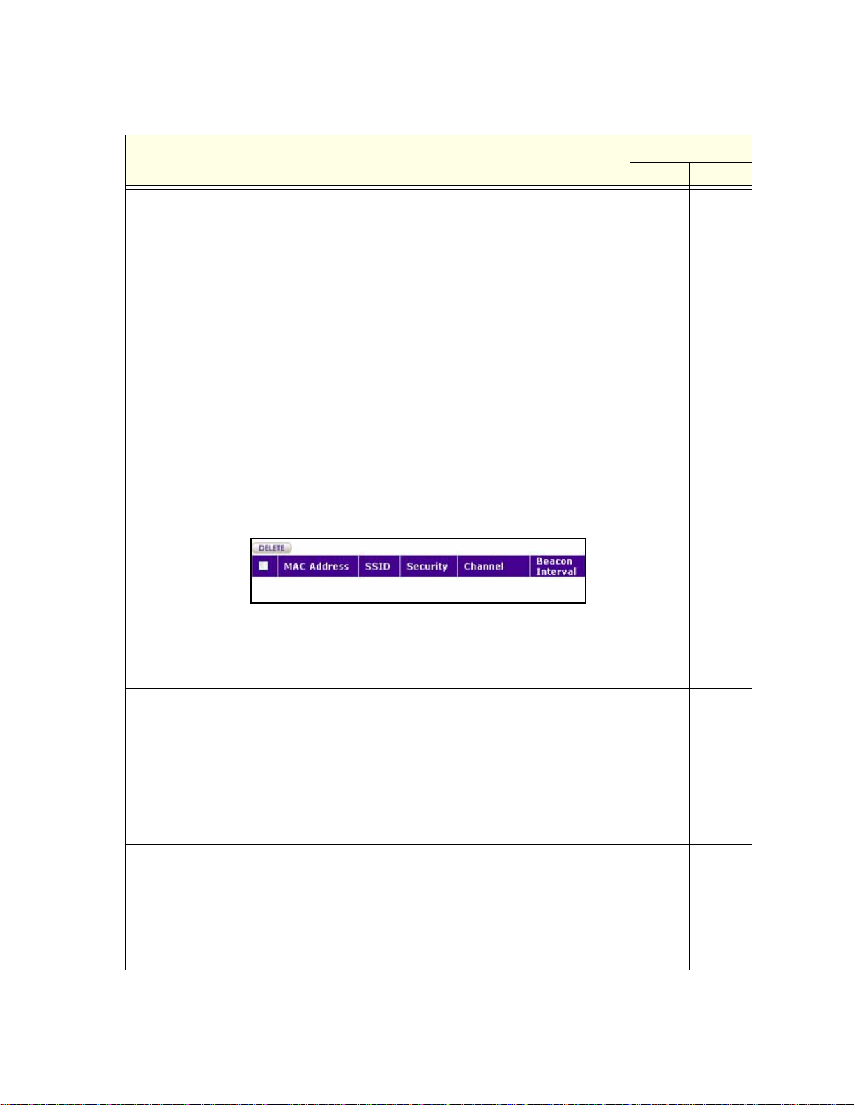
ProSafe Premium 3 x 3 Dual-Band Wireless-N Access Point WNDAP620
Table 24. IDS/IPS policies and p ol ic y rule s (co n tin u e d)
Policy Description Policy Rule
Threshold Notification
Known client
associating with
ad-hoc network
AP property
anged
ch
• Detection. Clients that should be connected to the secured
wireless network are instead connected to wireless access
points that are part of an ad hoc network.
• Res
• Solution.
• Detection. Unauthorized changes such as a change of SSID,
• Res
The changes that the IDS detects are listed in a table. The affected
wirel
the situation, access the web management interface of the affected
wireless access point, and reverse the changes.
ult. Wireless security might be compromised.
The clients are disconnected from the ad hoc
network.
security settings, or channel are made on a known wireless
access point in the network.
ult. Wireless security is compromised and clients cannot
connect to the wireless access point.
Note: The IDS detects that the properties of a known wireless
access poi
action.
nt in the network are changed, but the IPS does not take
ess access point is identified by its MAC address. To correct
0 Trap
0 Trap
To remove the detected chan
1. Select the check box to the left of the wireless access point for
you want to remove the changes from the table.
which
2. Above the table, click Delete.
Device probing for
access point
PS poll flood attack • Attack. Multiple power save (PS)–Poll frames (50 or more) are
s
• Detection. Multiple probe requests (30 or more) are sent to
collect information about the wireless access point for possible
future attacks. For example, it is suspect when there are too
many probe requests with a different SSID from same MAC
address.
• Res
• Solution. The
• Res
• Solution. PS-Poll
ult. An attack might occur, or wireless security might
become compromised.
wireless access point does not respond to probe
requests that do not contain its SSID.
sent to the wireless access point from an address that has a
spoofed MAC address of a legitimate client.
ult. Traffic that is intended for the legitimate client is sent to
the attacking address and is lost.
indication map (TIM) are rejected.
ges from the table:
frames without a corresponding traffic
30 Trap
50 Trap
Management and Monitoring
93
Page 94
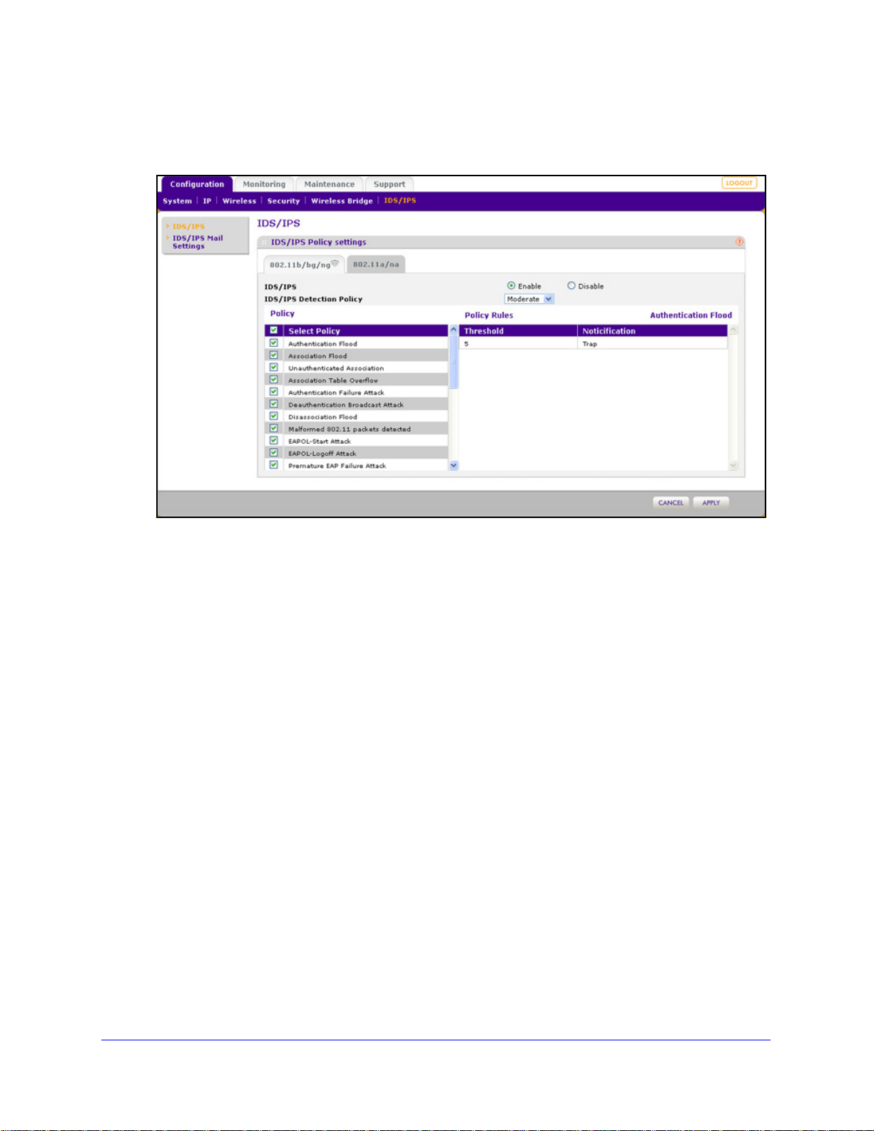
ProSafe Premium 3 x 3 Dual-Band Wireless-N Access Point WNDAP620
To enable and configure the IDS/IPS:
1. Select Configuration > IDS/IPS. The IDS/IPS screen displays:
Figure 54.
2. Select the Enable radio button. By default, the IDS/IPS is disabled.
pecify the detection policy by making a selection from the IDS/IPS Detection Policy
3. S
drop-down list:
• Mild. The wireless acce
• Mod
erate. The wireless access point scans for attacks every 5 seconds. This is the
ss point scans for attacks every 10 seconds.
default setting.
• Aggressive. The wireless acce
4. Option
al: Click a policy name to display the policy rules that are stated next to the policy in
ss point scans for attacks every second.
the table. IDS/IPS policy rules are not configurable.
5. Option
al: Clear check boxes for policies that you want to disable. By default, the check box
next to Select Policy in the table heading is selected, and all IDS/IPS policies are enabled.
6. Click Apply to save
your settings.
Management and Monitoring
94
Page 95
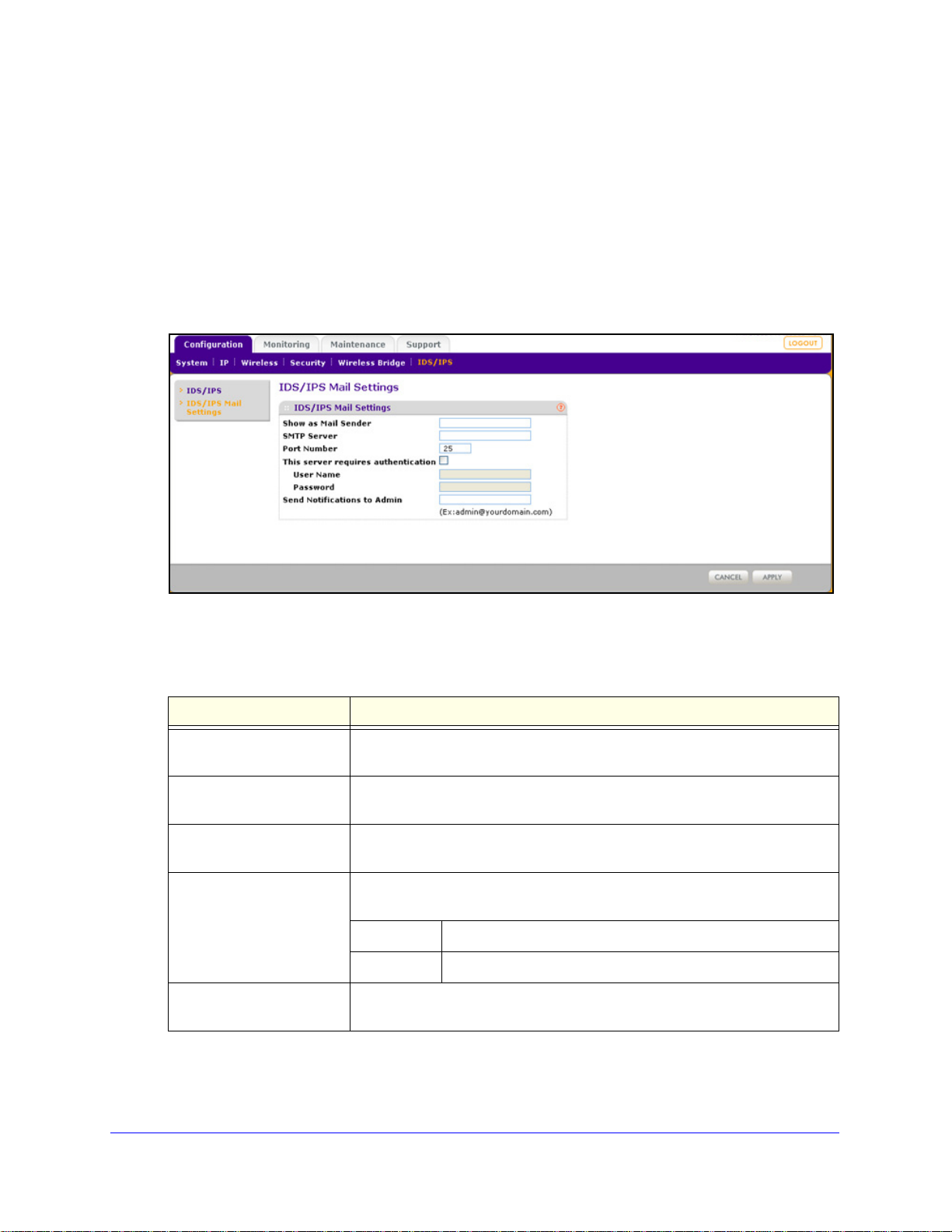
ProSafe Premium 3 x 3 Dual-Band Wireless-N Access Point WNDAP620
Configure Wireless Intrusion Detection and Prevention Mail Settings
For the IDS/IPS to send a notification according to the policy rule, you need to configure the email
settings.
To configure IDS/IPS email settings:
1. Select Con
figuration > IDS/IPS Mail Settings. The IDS/IPS Mail Settings screen
displays:
Figure 55.
2. Configure the settings as explained in the following table.
Table 25. IDS/IPS mail settings
Setting Description
Show as Mail Sender
SMTP Server The IP address or Internet name of the outgoing email SMTP server of your
Port Number
This server requires
tication
authen
Send Notifications to Admin The email address to which the notifications should be sent. Typically, this is
3. Click App
ly to save your settings.
A descriptive name of the sender for email id
example, enter WNAP620-IDS-IPS@company.com.
ISP.
The port number of the outgoing email SMTP server of your ISP. The default
port number is 25.
If the SMTP server requires authentication, select the This server requires
authentication check box, and enter the user name and password.
User Name The user name for SMTP server authentication.
Password The password for SMTP server authentication.
e email address of the administrator.
th
Management and Monitoring
95
entification purposes. For
Page 96

ProSafe Premium 3 x 3 Dual-Band Wireless-N Access Point WNDAP620
Monitor Traps, Counters, and Ad Hoc Networks
The IDS/IPS monitoring screens provide information about the most recent attacks, the
number of occurrences per attack, and ad hoc networks. This information is read only.
Most Recent Attacks
To display the last 50 attacks against the wireless access point and its clients:
Select Monitoring > IPS/IDS > T
Figure 56.
raps. The Traps screen displays.
To update the information onscreen, click Refresh.
The following table explains the fie
Table 26. Traps fields
Setting Description
Attack Name The name of the attack that corresponds to a policy in Table 24 on page 89.
lds of the Traps screen:
Time Stamp The time that the attack occurred.
IPS If the IPS has prevented the attack, the field disp
attack, or the IPS is not applicable to the attack, the field displays No.
Attack Counter
To display the number of occurrences per attacks:
Select Monitoring > IPS/IDS > Counte
Management and Monitoring
rs. The Counters screen displays.
96
lays Yes. If the IPS did not prevent the
Page 97

ProSafe Premium 3 x 3 Dual-Band Wireless-N Access Point WNDAP620
Figure 57.
To update the information onscreen, click Refresh.
Ad Hoc Networks
To display the ad hoc networks and their associated clients:
Select Monit
oring > IPS/IDS > Adhoc Networks. The Adhoc Network screen displays.
Management and Monitoring
97
Page 98

ProSafe Premium 3 x 3 Dual-Band Wireless-N Access Point WNDAP620
Figure 58.
To update the information onscreen, click Refresh.
The following table explains the fields
of the Adhoc Networks screen:
Table 27. Ad hoc network fields
Setting Description
Client MAC Address The MAC address of the client that is connected to the ad hoc network.
BSSID The BSSID of the ad hoc network.
Note: A wireless access point that is connected to a w
stations is called a basic service set (BSS). The basic service set identifier (BSSID)
differentiates one WLAN from another.
Wired Connectivity If the ad hoc network has wire d connectivity, the field displays YES. If the ad hoc
network doe
s not have wired connectivity, the field displays NO.
ired network and a set of wireless
Management and Monitoring
98
Page 99

5. Advanced Configuration
This chapter describes how to configure the advanced features of the wireless access point. The
chapter includes the following sections:
• Configure IPv6 Settings and Optional DHCPv6 Server Settings
• Configure Spanning Tree Protocol, 802.1Q VLAN, and
• Configure Hotspot Settings
• Configure Advanced Wireless Settings
• Configure Advanced Quality of Service Settings
• Configure Quality of Service Policies
• Configure Wireless Bridging
Link Layer Discovery Protocol
Configure IPv6 Settings and Optional DHCPv6 Server Settings
5
The wireless access point supports IPv6:
ou can manage the wireless access point from an IPv6 address.
• Y
• The wire
• The DHCPv6 server
wireless clients, either through stateless or stateful allocation.
less access point can function as an IPv6 DHCP client.
of the wireless access point can allocate IPv6 addresses to its
Configure the IPv6 Settings
Note: For information about how to configure the IPv4 settings, see
Configure the IPv4 Settings on page 25.
99
Page 100
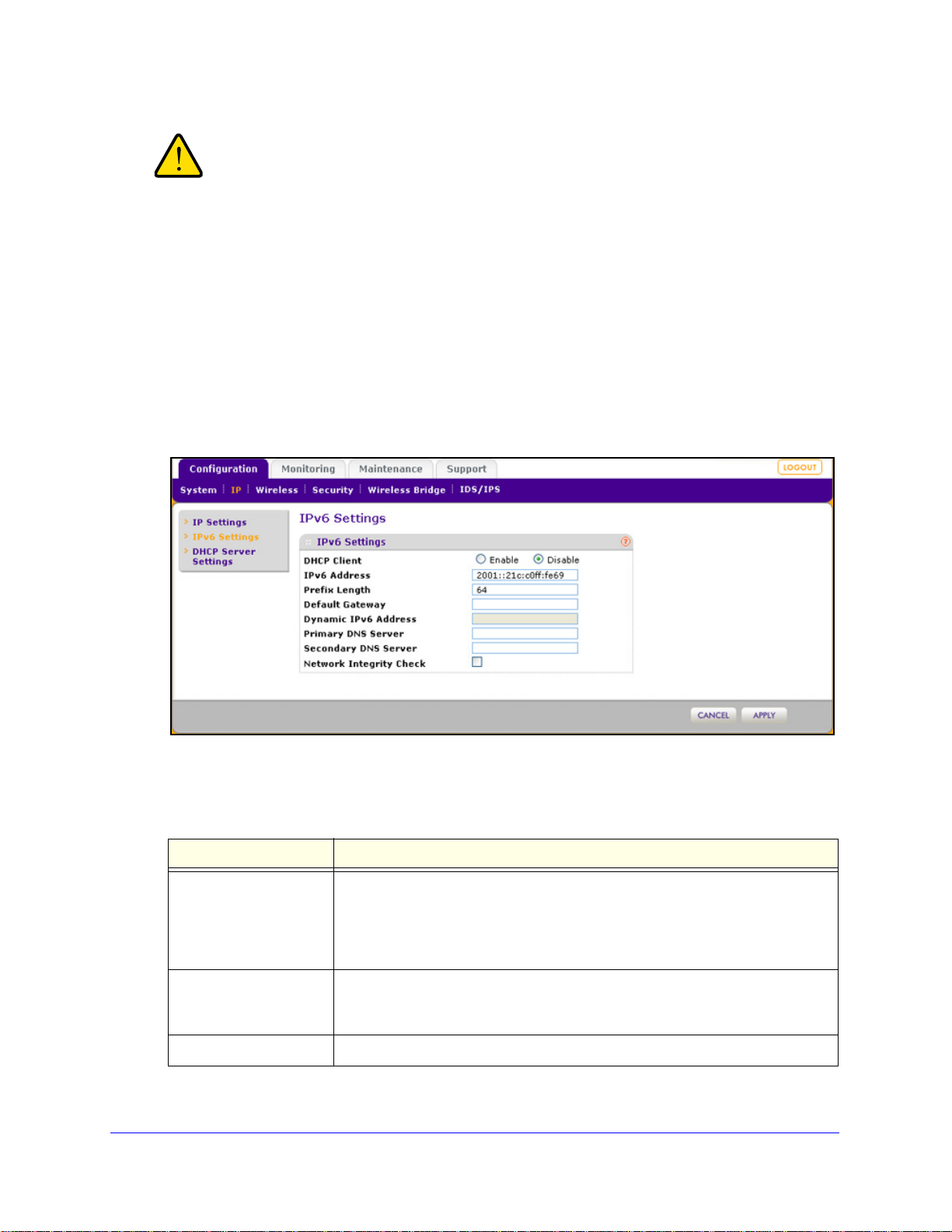
ProSafe Premium 3 x 3 Dual-Band Wireless-N Access Point WNDAP620
WARNING:
If you enable the DHCP client, the IP address of the wireless
access point changes when you click Apply, causing you to lose
your connection to the wireless access point. You then need to
use the new IP address to reconnect to the wireless access point.
Tip: If you enable the DHCP client on the wireless access point, you can
discover the new IP address of the wireless access point by accessing
the DHCP server on your LAN, or by using a network IP address scanner
application.
To configure the IPv6 settings:
1. Select Configuration
> IP > IPv6 Settings. The IP Settings screen displays:
Figure 59.
2. Configure the IPv6 settings as explained in the following table:
Table 28. IPv6 settings
Setting Description
DHCP Client By default, the Dynamic Host Configuration Protocol
IPv6 Address Enter the IP address of your wireless access
Prefix Length Enter the prefix length for the IPv6 address. T
(DHCP) client is disabled. If
you have a DHCPv6 server on your LAN and you select the Enable radio button,
the wireless access point receives its dynamic IPv6 address, prefix length, and
default gateway settings automatically from the DHCPv6 server on your network
when you connect the wireless access point to your LAN.
point. The default IP address is
2001::21c:c0ff:fe69. To change the address, en ter an unused IPv6 address
from the address range used on your LAN.
he default prefix length us 64.
Advanced Configuration
100
 Loading...