

Page 1

202-10524-02
February 2010
NETGEAR, Inc.
350 East Plumeria Drive
San Jose, CA 95134
ProSafe® Plus Switch
Configuration Utility User
Guide
Page 2

ii
1.0 February 2010
© 2010 by NETGEAR, Inc. All rights reserved.
Trademarks
NETGEAR and Auto Uplink are trademarks or registered trademarks of NETGEAR, Inc..
Microsoft, Windows, and Windows NT are registered trademarks of Microsoft Corporation.
Other brand and product names are registered trademarks or trademarks of their respective holders.
Statement of Conditions
In the interest of improving internal design, operational function, and/or reliability, NETGEAR reserves the right to
make changes to the products described in this document without notice.
Product and Publication Details
Model Number: ProSafe® Plus Switches
Publication Date: February 2010
Product Family: ProSafe® Plus Switch
Product Name: ProSafe® Plus Switch Configuration Utility
Home or Business Product: Business
Language: English
Publication Part Number: 202-10524-02
Publication Version Number: 1.0
Page 3

iii
v1.0, September 2009
Contents
Chapter 1
Getting Started
Installing the Utility ..........................................................................................................1-1
Overview of Utility Features ............................................................................................1-1
Uninstalling the Utility .....................................................................................................1-4
Discovering Switches .....................................................................................................1-5
Overview of Utility Features ............................................................................................1-6
Switch Settings .........................................................................................................1-7
Default Settings ........................................................................................................1-7
Chapter 2
System Configuration
System Features ............................................................................................................2-2
Status .............................................................................................................................2-2
Switch Selection .......................................................................................................2-2
Switch Information ....................................................................................................2-3
DHCP Mode Selection .............................................................................................2-3
Manually Setting the IP Address Information ...........................................................2-4
Maintenance ...................................................................................................................2-4
Change Password ....................................................................................................2-4
Device Reboot ..........................................................................................................2-4
Reset Factory Defaults .............................................................................................2-5
Firmware Upgrade ...................................................................................................2-5
Monitoring .......................................................................................................................2-5
Port Statistics ...........................................................................................................2-5
Port Mirroring ...........................................................................................................2-5
Cable Test ................................................................................................................2-6
Page 4

iv
v1.0, September 2009
Chapter 3
Virtual LAN Configuration
Port Based Configuration ...............................................................................................3-1
Basic Port Based Configuration ...............................................................................3-1
Advanced Port Based Configuration ........................................................................3-2
802.1Q Based Configuration ..........................................................................................3-2
Basic 802.1Q Based Configuration ..........................................................................3-2
Advanced 802.1Q Based Configuration ...................................................................3-2
VLAN Configuration ...........................................................................................3-3
VLAN Membership ............................................................................................3-3
Port PVID ...........................................................................................................3-4
Port Tagging ......................................................................................................3-4
Chapter 4
Quality of Service Configuration
QoS Global Configuration ...............................................................................................4-2
Port Based Priority ...................................................................................................4-2
802.1p Based Priority ...............................................................................................4-3
Rate Limiting ...................................................................................................................4-4
Broadcast Filtering ..........................................................................................................4-4
Chapter 5
Help
Online Help .....................................................................................................................5-1
User Guide ...............................................................................................................5-1
Support Information ..................................................................................................5-1
About the Utility ...............................................................................................................5-2
Page 5
i
v1.0, February 2010
About This Manual
The ProSafe® Plus Switch Configuration Utility User Guide describes how to use the Switch
Configuration Utility. The information in this manual is intended for readers with intermediate
computer and internet skills.
Conventions, Formats, Scope, and Audience
The conventions, formats, and scope of this manual are described in the following paragraphs:
• Typographical Conventions. This manual uses the following typographical conventions
• Formats. This manual uses the following formats to highlight special messages:
Note: Product updates are available on the NETGEAR website at http://
kbserver.netgear.com.
Italic Emphasis, books, CDs, file and server names, extensions
Bold User input, IP addresses, GUI screen text
Fixed Command prompt, text, code
italic URL links
Note: This format is used to highlight information of importance or special interest.
Tip: This format is used to highlight a procedure that will save time or resources.
Page 6

1.0 February 2010
ii
• Scope. This manual is written for the switch utility according to these specifications:
This document provides examples of the use of the management utility in a typical network.
• Audience. Use this guide if you have at least intermediate computer and internet skills and are
responsible for configuring and operating a network with ProSafe
®
Plus switches.
To obtain the greatest benefit from this guide, you should have a basic knowledge of
networking concepts.
Additional Documentation
Before proceeding, read the Installation Guides for the ProSafe® Plus Switches used in your
network. These documents may be found at: http://www.NETGEAR.com.
How to Print This Manual
Your computer must have the free Adobe Acrobat reader installed in order to view and print PDF
files. The Acrobat reader is available on the Adobe Web site at
http://www.adobe.com.
Revision History
Product ProSafe® Plus Switch Configuration Utility
Manual Publication Date February 2010
Tip: If your printer supports printing two pages on a single sheet of paper, you can
save paper and printer ink by selecting this feature.
Part Number
Version
Number
Description
202-10524-02 1.0 ProSafe
®
Plus Switch Configuration Utility User Guide
Page 7
1-1
v1.0, February 2010
Chapter 1
Getting Started
In order to make use of the enhanced features on ProSafe® Plus switches you can install and use the
ProSafe® Plus Switch Configuration Utility. The utility is on the Resource CD shipped with ProSafe® Plus
switches.
Installing the Utility
If an earlier version of the utility is already present on the PC, it will be replaced by the newer version.
Newer versions of the utility are backwards compatible and support all previously released ProSafe® Plus
switches. If the version of the utility you are trying to install is older than the one already installed on the PC,
the installation will not be performed.
If you have not already installed the utility, install it now. To install the utility:
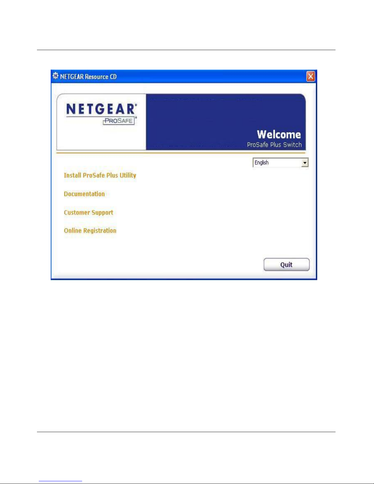
1. Insert the switch Resource CD into the PC that you want to use to manage your switches. The Resource
CD home page will display.
Note: The utility must be installed on a PC in the network containing the switches to be managed
and is only supported on MS Windows.
Note: You can install the utility on any Windows PC(s) connected to the network containing the
switches to be managed.
Page 8
ProSafe® Plus Switch Configuration Utility User Guide
1-2 Getting Started
v1.0, February 2010
2. Resource CD pages and the installation guide for the switch can be displayed in several languages. A
pull down menu for language selection is in the upper right corner of the Resource CD home screen.
3. Click on Install ProSafe® Plus Utility to install the utility program on your PC.
Page 9
ProSafe® Plus Switch Configuration Utility User Guide
Getting Started 1-3
v1.0, February 2010
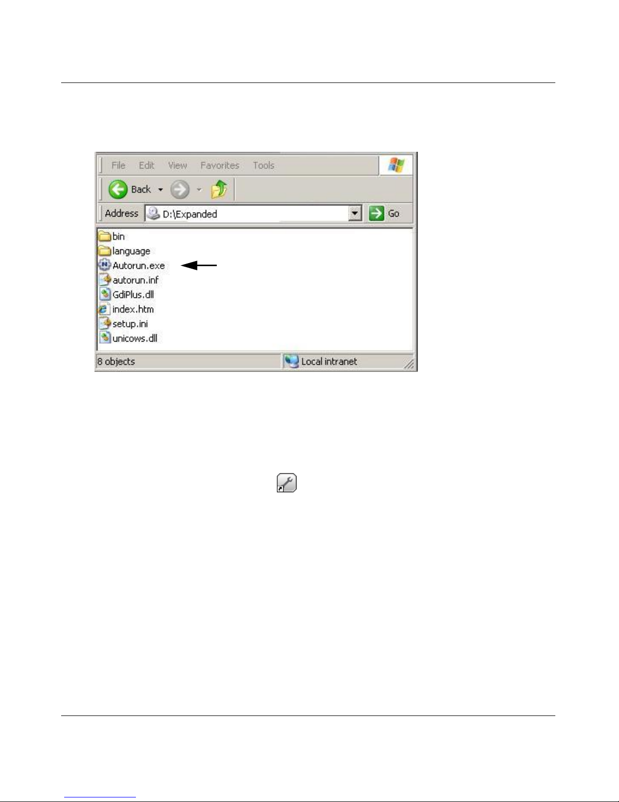
Note: If the Resource CD home page does not display, your PC may have the Autorun feature disabled. You
can enable your PC’s Autorun feature or use the PC’s file manager to navigate to the CD and double
click on Autorun.exe.
Note: The name of the utility may vary slightly for different ProSafe® Plus switch models.
The utility uses two network programs, WinPcap and Adobe AIR to process network commands. If not
already installed on your PC, these two programs will also be installed. They will be placed in your program
directory.
4. Click Install Utility. This will create a NetGear subdirectory under the \Program Files directory on
your PC. Installation then copies the utility program into the \Program Files\NetGear\ProSafe Plus
Utility directory and places a utility icon ( ) on the PC desktop.
5. The WinPcap and Adobe AIR programs can be used by other network applications and may already be
installed on your PC. If so, a message will be displayed asking if you want to reinstall WinPcap. Click
Cancel unless you think the installed WinPcap is an older version or might be corrupted. Clicking
Cancel will end the WinPcap portion of installation and will continue installing the remaining
components.
6. If the Adobe AIR program is already installed, an already installed message will be displayed. Clicking
Close will end the Adobe AIR portion of installation.
7. When the InstallShield Wizard Complete screen displays you can check a box to launch the utility
following installation. If you do not want to launch the utility at this time, just click Finish.
8. Installation is complete. If you checked the “Launch following installation” box, the utility will
automatically start. If not, you can launch the utility by clicking on the utility icon on your desktop.
Autorun
Page 10
ProSafe® Plus Switch Configuration Utility User Guide
1-4 Getting Started
v1.0, February 2010
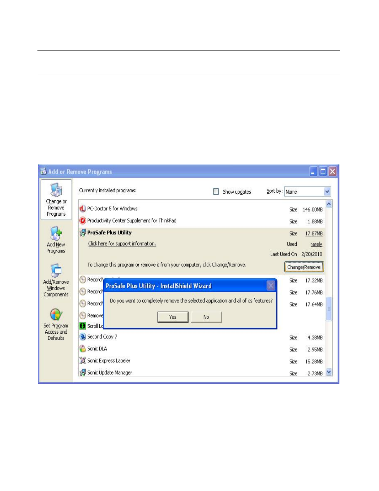
Uninstalling the Utility
To uninstall the utility:
1. Use your PC’s Add or Remove Programs command, Start > Control Panel > Add or Remove
Programs.
2. Select ProSafe Plus Utility and click Change/Remove.
3. When you are asked if you want to completely remove the selected application, click Yes.
4. You can also remove the WinPcap and AIR programs if they are not needed by another program.
.
Page 11
ProSafe® Plus Switch Configuration Utility User Guide
Getting Started 1-5
v1.0, February 2010
Discovering Switches
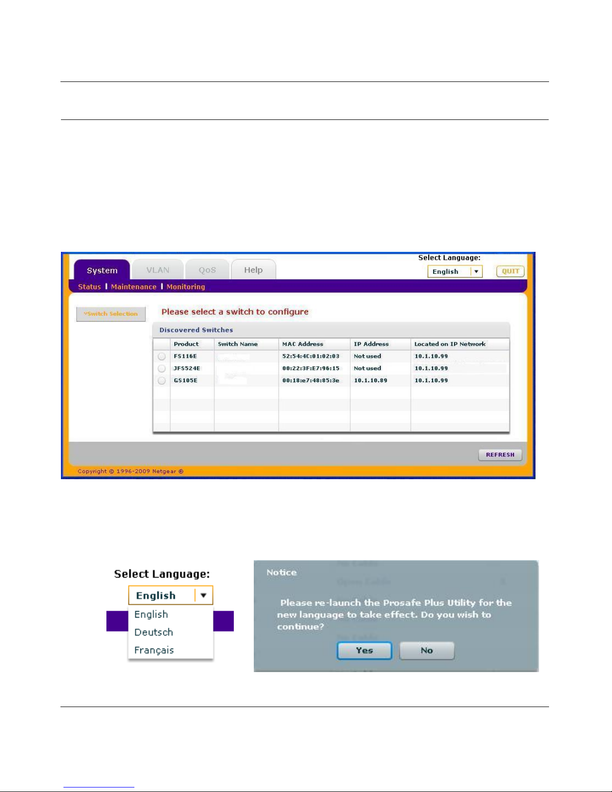
When the utility is launched, it immediately searches the network for ProSafe® Plus switches.
Note: Local PC firewall applications such as Symantec Endpoint Protection can prevent the utility from
communicating with the switches. If the utility is unable to discover your switches and you are using a
local firewall, you will need to turn off the firewall function in order for discovery to work.
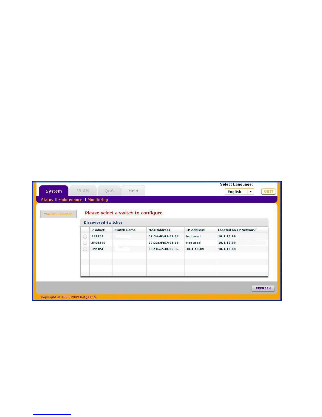
Within a few seconds the utility will discover and list all ProSafe® Plus switches in your network or in the
same broadcast domain. Discovery will continue through the network until blocked by a router or firewall.
The discovered switches are displayed as shown below.
You can now select a switch to configure or display status.
Note: At this point you can select an alternate language for the Utility user interface. Click on the Select
Language pull down menu and click on the desired language. You will be asked to restart the Utility
to enable the selected language.
Page 12
ProSafe® Plus Switch Configuration Utility User Guide
1-6 Getting Started
v1.0, February 2010
Overview of Utility Features
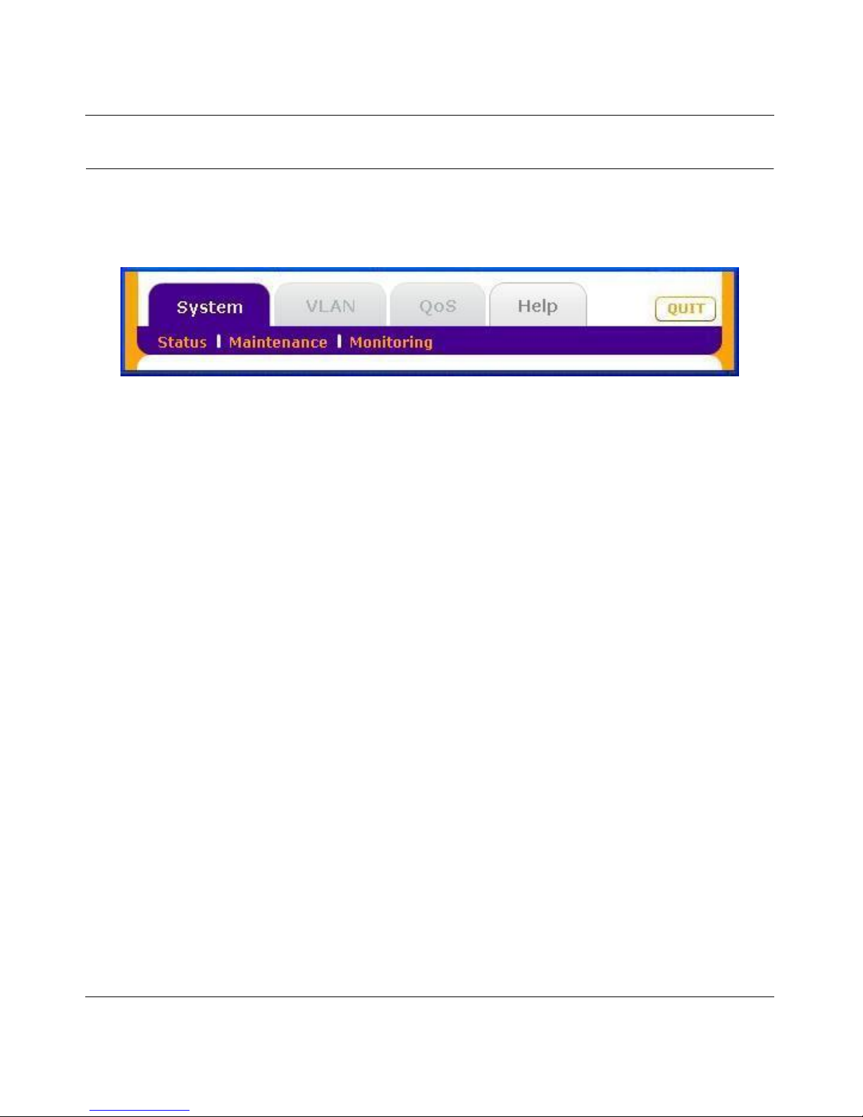
The utility configures switch features and provides status and support information. The features are arranged
on tabs as shown in the following figure:
System (General Configuration and Information)
Status - indicates which switches are present and if they are operational. If your switch supports the switch
information feature you can display additional information such as IP Address, Subnet Mask, and Gateway
Address.
Maintenance - allows you to change administrator password, reboot the switch, reset to factory default
settings, and if your switch supports it, upgrade switch firmware.
Monitoring - displays port statistics (packets sent or received), tests cable connections, and allows you to
mirror ports.
VLAN (Virtual LAN networks)
Port Based - allows you to assign ports to virtual networks.
802.1Q - allows you to create virtual networks using 802.1Q criteria.
QoS (Quality of Service)
Port based - allows you to assign communication priorities to ports.
802.1p based - uses communication priorities from 802.1p tags in the data.
Rate Limit - allows you to set maximum data rates for ports.
Broadcast Filtering - protects your network from broadcast packet storms that can interfere with the
processing of normal data.
Help
Online Help - online access to technical support information and this manual.
About - version information.
Page 13

ProSafe® Plus Switch Configuration Utility User Guide
Getting Started 1-7
v1.0, February 2010
Note: It is possible that you can make port settings that will block further access to the switch you are
configuring. If this occurs you can reset the switch manually to restore access. Your previous settings
will be lost.
Switch Settings
The features on each tab are explained in the following chapters:
Chapter 2 System Configuration - describes general management features
Chapter 3 Virtual LAN Configuration - describes how to create and configure VLAN groups
Chapter 4 Quality of Service (QoS) - describes how to set data priorities using Global Configuration, Rate
Limiting, and Broadcast filtering
Chapter 5 Help - describes how to get online support information
Page 14
ProSafe® Plus Switch Configuration Utility User Guide
1-8 Getting Started
v1.0, February 2010
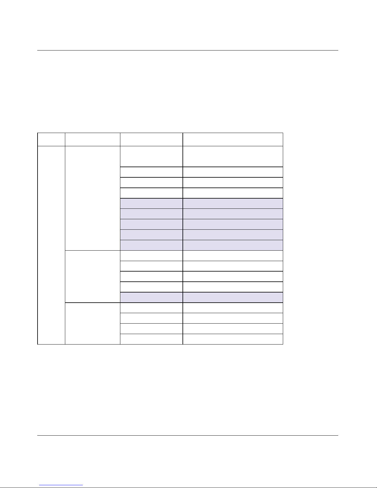
Default Settings
All of the ProSafe® Plus Switch features have default settings. You do not need to configure any settings in
order to use the ProSafe® Plus switches.
The following table lists the default values for switch settings. Shaded features are not configurable on all
switches.
Table 1-1. Feature Default Values
Tab Menu Feature Default Value
System
Status
Switch Selection No switch selected
Names All names blank
Passwords “password” for all switches
Switch Information
DHCP Mode Enabled
IP Address 192.168.0.239
Subnet Mask 255.255.255.0
Gateway Address 192.168.0.254
Maintenance
Change Password All fields blank
Device Reboot Unchecked
Factory Default Unchecked
Firmware Upgrade Filename blank
Monitoring
Port Statistics 0
Mirroring Disabled
Cable Tester OK or No Cable for each port
Page 15

ProSafe® Plus Switch Configuration Utility User Guide
Getting Started 1-9
v1.0, February 2010
VLAN
Port Based
Basic Disabled
Advanced Disabled
802.1Q
Basic Disabled
Advanced Disabled
QoS
QoS
Global Configuration
QoS Mode Port based
Port Priority Low priority for each port
Rate Limit
Ingress No limit
Egress No limit
Broadcast Filtering Disabled
Help
Online Help
Support -
User Guide -
About the Utility About the Utility -
Table 1-1. Feature Default Values
Tab Menu Feature Default Value
Page 16

ProSafe® Plus Switch Configuration Utility User Guide
1-10 Getting Started
v1.0, February 2010
Page 17
2-1
v1.0, February 2010
Chapter 2
System Configuration
The System tab lets you select a switch to manage, display general information about the switch, perform
basic switch maintenance, and monitor data flow through the switch.
System features are:
Status - indicates which switches are present and if they are operational.
Maintenance - allows you to change administrator password, reboot the switch, reset to factory default
settings and if the feature is available on the selected switch, upgrade switch firmware.
Monitoring - displays port statistics (packets sent or received), tests cable connections, and allows you to
mirror ports.
All of the features have default settings. You do not need to configure any settings in order to use the
ProSafe® Plus switches. Refer to “Default Settings” on page 1-8 for a list of default system settings.
Page 18

ProSafe® Plus Switch Configuration Utility User Guide
2-2 System Configuration
v1.0, February 2010
System Features
Table 2-1 lists features available on the System tab.
The Switch Selection remains in effect until you select a different switch or quit the utility.
Status
The Status menu allows you to select a switch and display switch information.
Switch Selection
In order to use any of the System tab features you must first select a switch. Click on the radio button for the
desired switch. You will be asked to enter the password for the selected switch. The default password for all
switches is “password”. When you enter the switch password and click on Login, the port status for the
switch will be displayed. You can then select Switch Information for additional switch status, or select
Maintenance, or Monitoring for other switch features. When you select a switch, the Status menu displays
the status (up or down) of the ports on the switch and the speed of the device connected to the port. The
switch automatically senses the speed of the device connected to each port.
Table 2-1. System Tab Features
Feature Description
Status
Switch Selection Selects a switch to configure
Switch Information Displays general information for the selected switch
Maintenance
Change Password Changes password for the selected switch
Device Reboot Restarts the selected switch using configured settings
Factory Default Restarts the selected switch with factory default settings
Firmware Upgrade Updates the selected switch with a firmware update saved on the PC
Monitoring
Port Statistics Displays port network traffic for the selected switch
Mirroring Allows a port to receive data sent to another port
Cable Tester Checks cable connections for the ports of the selected switch
Page 19
ProSafe® Plus Switch Configuration Utility User Guide
System Configuration 2-3
v1.0, February 2010
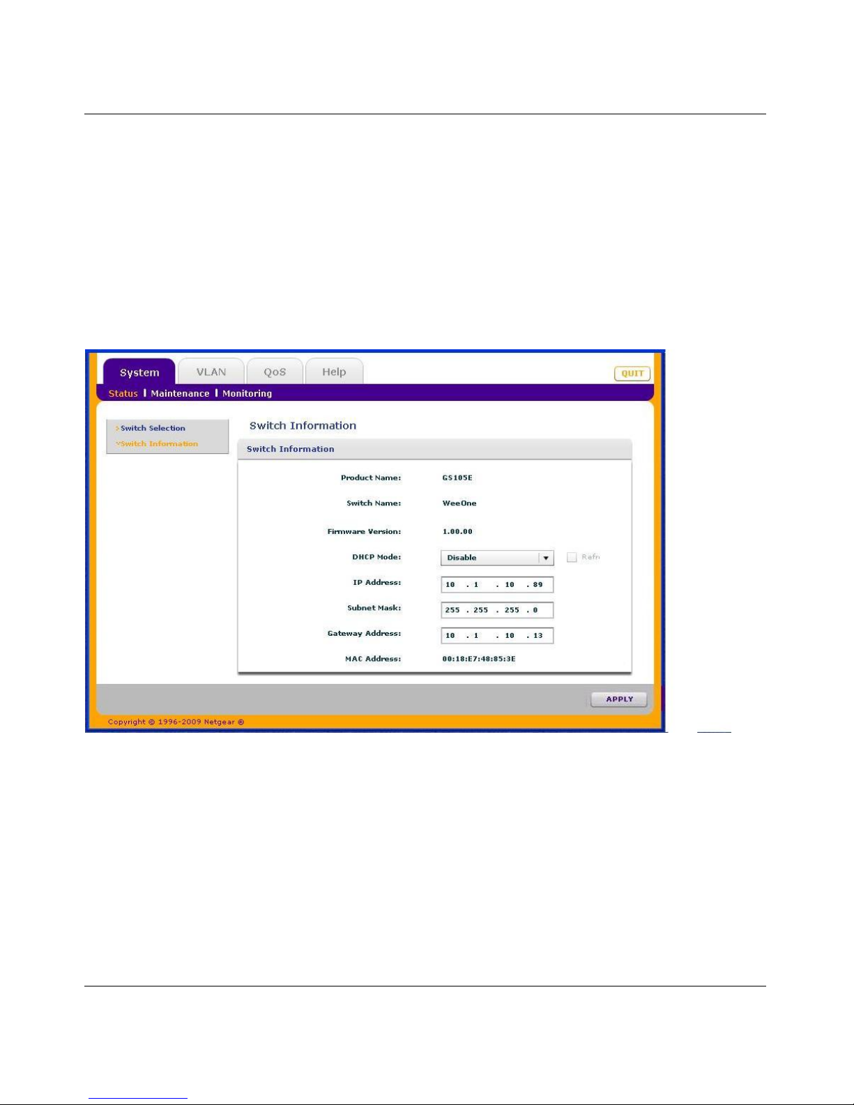
You can assign a name to the selected switch by entering the name in the Switch Name field.The switch
name can be up to 20 characters. The switch is updated with a new name when you press the Enter key
before leaving the Switch Name field.
Switch Information
The Switch Information feature displays additional information about the selected switch. This information
will vary depending on the model of the selected switch. If the selected switch supports the Switch
Information feature, you can use it to display or configure the IP Address, Subnet Mask, and Gateway
Address.
DHCP Mode Selection
The Switch Information screen contains a field for DHCP (Dynamic Host Configuration Protocol) Mode
selection. When you enable this setting the switch will obtain a network IP address from a DHCP server in
the network. Each time the switch is powered on or reset, it will request an IP address from a DHCP Server
in the Network. This is called a Dynamic IP address. If there is no DHCP server in the network, a timeout
message will be displayed. If the switch fails to retrieve an IP address from a DHCP server, a default IP
address of 192.168.0.239 will be entered.
To enable DHCP operation:
1. Select System >Switch Information. The Switch Information screen will display.
Page 20

ProSafe® Plus Switch Configuration Utility User Guide
2-4 System Configuration
v1.0, February 2010
2. Click the list arrow in the DHCP Mode list box.
3. Select Enable then click Apply.
The IP Address, Subnet Mask, and Gateway Address fields will be disabled (greyed out).
To disable DHCP address assignment, repeat the previous procedure and select Disable. When you click
Apply, you will able to manually enter IP Address, Subnet Mask, and Gateway Address information.
Manually Setting the IP Address Information
You can manually enter IP address and subnet mask values for the switch as well as the address of the
Gateway device to be used by the switch.
To define an IP interface information:
1. Click System > Status > Switch Information. The Switch Information screen displays.
2. Select Disable for the DHCP Mode. The IP Address, Subnet Mask, and Gateway Address fields will
be enabled.
3. Enter the IP Address, Subnet Mask, and if available Gateway Address and click Apply.
Maintenance
The Maintenance feature allows you to change the password for the selected switch, perform a device
reboot, reset the switch to its factory default settings, or upgrade the switch firmware.
Change Password
To change the password for a switch:
1. Select System > Maintenance. The Maintenance menu and Change Password feature will display.
2. Enter the old password (default is “password”) and the new password.
3. Click Apply.
Device Reboot
Warning: Rebooting the switch will briefly disrupt network traffic through the switch.
To reboot the selected switch:
1. Select System > Maintenance > Device Reboot. The Device Reboot dialog will display.
2. Check the box in the Device Reboot dialog.
3. Click Apply.
Page 21

ProSafe® Plus Switch Configuration Utility User Guide
System Configuration 2-5
v1.0, February 2010
Reset Factory Defaults
Warning: Resetting the factory defaults may briefly disrupt network traffic through the switch.
To reset the factory default settings on the selected switch:
1. Select System > Maintenance > Factory Default. The Factory Default dialog will display.
2. Check the box in the Factory Default dialog.
3. Click Apply.
Firmware Upgrade
Warning: After downloading of firmware is complete, the switch will reboot automatically. This
will briefly disrupt network traffic through the switch.
In order to upgrade switch firmware you must first download a firmware upgrade file for the selected switch
from the NETGEAR support website to your PC.
To upgrade firmware on the selected switch:
1. Select System > Maintenance > Firmware Upgrade. The Firmware Upgrade dialog will display.
2. Click the Browse button and navigate to the location on your PC containing the firmware upgrade file.
3. Select the upgrade file and click Apply. The firmware will be downloaded from your PC to the switch
and the switch will automatically reboot.
Monitoring
The Monitoring menu provides statistics on port data volume, allows you to configure port mirroring and on
some switch models perform cable testing.
Port Statistics
To view port statistics (bytes received, bytes sent, packet errors):
1. Select System > Monitoring. The Port Statistics for the selected switch will display.
Port Mirroring
Port mirroring allows a port to see the data on another port.
To have a switch port see the data on another port:
1. Select System > Status, and select the switch.
2. Select Monitoring > Mirroring. The Mirroring page will display.
Page 22
ProSafe® Plus Switch Configuration Utility User Guide
2-6 System Configuration
v1.0, February 2010
3. Enable Mirroring.
4. Select the Source Port or ports.
5. Select the Destination Port from the pull down list and click Apply. Data on the source port will now
also be routed to the destination port.
Cable Test
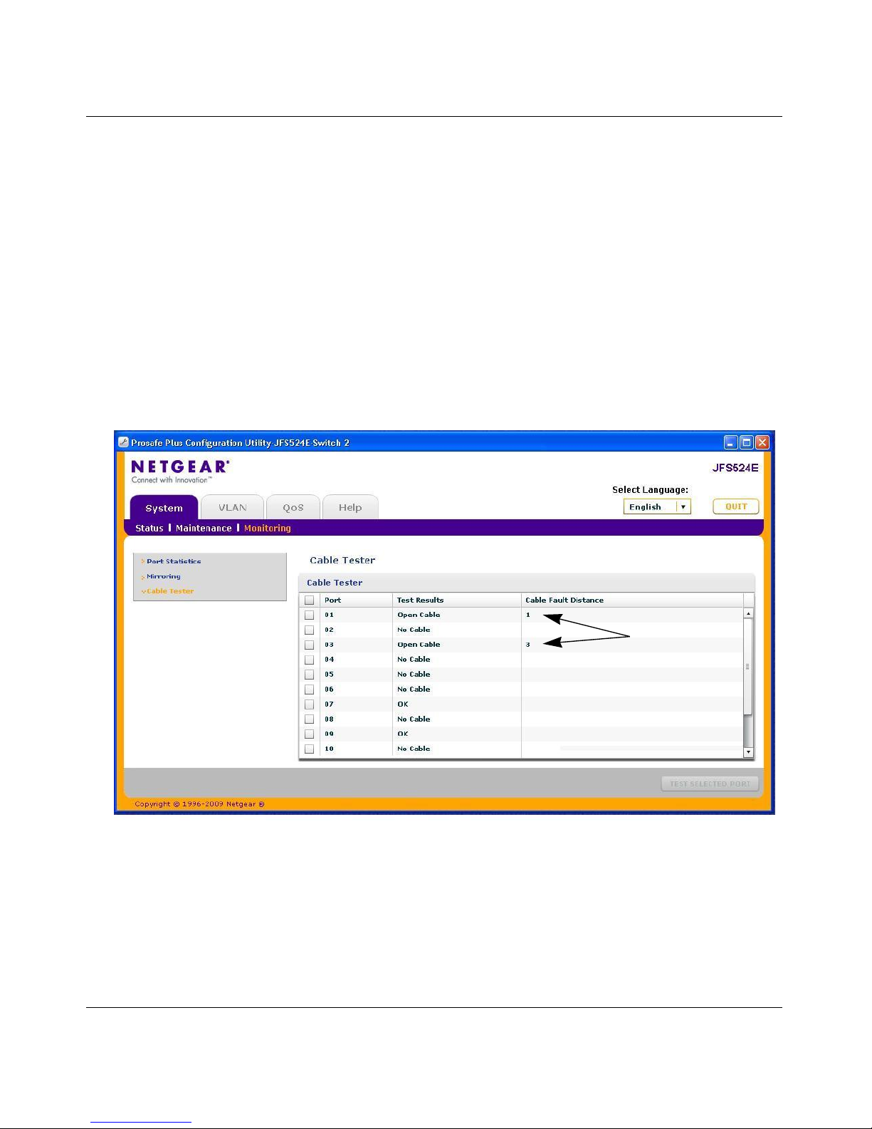
Some switch models have a cable testing feature that allows you to check for cable faults. If a cable fault is
found on a port the cable test will give an estimate of the distance of the fault from the switch.
To perform a cable test:
1. Click on the System tab and select Monitoring and then Cable Tester. The Cable Tester results will
display.
Distance to cable
fault in meters
Page 23
3-1
v1.0, February 2010
Chapter 3
Virtual LAN Configuration
Virtual LANs are made up of networked devices grouped together logically into separate networks. The
Switch Configuration Utility allows you to group ports on a switch to create a virtual network made up of
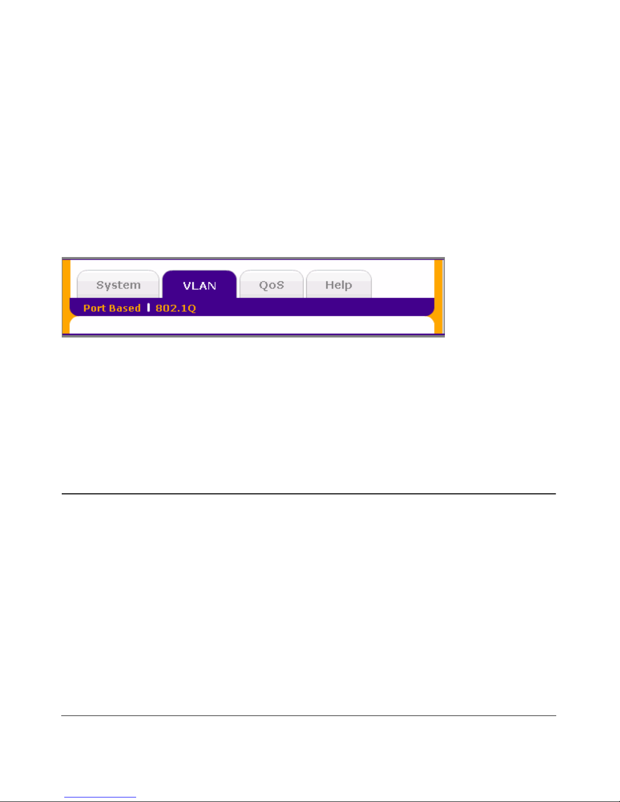
the devices connected to the ports. VLANs can be grouped using Port Based or 802.1Q criteria
.
Port Based - allows you to assign ports to virtual networks. Data from a port that is a member of a VLAN
group will be restricted to other members of that VLAN group. This is an easy way to partition a network
into private sub networks.
802.1Q - allows you to create virtual networks using 802.1Q criteria. When using 802.1Q VLAN
configuration, you configure ports to be a part of a VLAN group. When a port receives data tagged for a
VLAN group, the data will be discarded unless the port is a member of the VLAN group. This technique is
useful if you need to communicate with devices outside of your local network as well as still receiving data
from other ports not in your VLAN group. It requires that you know the VLAN group IDs used.
Port Based Configuration
Port Based Virtual LAN configuration assigns ports on the selected switch to a Virtual LAN Group. The
number of VLANs that can be created is limited to the number of ports on the switch. The Basic Port Based
VLAN Configuration page is designed to help you to partition your network into different segments. Ports
with the same ID are grouped into the same VLAN group. If all the VLAN groups share the same uplink to
the Internet or servers, enter 'all' in the VLAN Group field for the port that you want to use for the uplink.
Basic Port Based VLAN Configuration
To assign members of a VLAN group using Basic Port-Based configuration:
1. Select the switch.
2. Select VLAN. This will display the Basic Port-Based VLAN configuration page.
3. Select Enable. A message will display asking if you want to delete previous VLAN settings.
Page 24

ProSafe® Plus Switch Configuration Utility User Guide
3-2 Virtual LAN Configuration
v1.0, February 2010
4. Click Yes. The Basic Port Based VLAN Configuration screen will display.
5. For each port to be added to the group, select the port and then the VLAN Group.
6. When you are finished adding ports to a particular VLAN Group, click Apply.
Advanced Port Based VLAN Configuration
The advanced port-based configuration uses a slightly different user interface to allow you to assign ports to
multiple VLAN groups.
To assign members of a VLAN group using Advanced Port-Based Configuration:
1. Select the switch.
2. Click on the VLAN tab. This will display the Port-Based VLAN configuration page.
3. Select Advanced. This will display the Advanced Port-Based VLAN configuration page.
4. Select Enable. A message will display asking if you want to delete previous VLAN settings.
5. Click Yes. The Advanced Port-Based VLAN configuration screen will display.
6. VLAN IDs are limited to the number of ports on the switch, 1-5 for a five port switch. Select a VLAN
ID from the VLAN identifier field and check the ports that you want to add to the VLAN and click
Apply. If you want to create more VLANs, repeat this step with another VLAN ID.
802.1Q Based Configuration
802.1Q VLAN configuration can be done using basic or advanced methods.
Basic 802.1Q VLAN Configuration
In Basic 802.1Q VLAN configuration you configure ports to a VLAN Group ID (1-4093 or all). To
configure ports using 802.1Q criteria:
1. Select the switch.
2. Select VLAN. This will display the Port-Based VLAN configuration page.
3. Select 802.1Q on the menu.
4. Select Enable.
5. For each port to be configured, enter the VLAN Group ID (1-4093 or all) in the field below the port.
6. When you are finished configuring ports, click Apply.
Advanced 802.1Q VLAN Configuration
In Advanced 802.1Q VLAN configuration you configure ports to a VLAN Group ID (1-4093 or all). The
advanced configuration feature allows you to create and update VLAN groups with additional information.
Page 25

ProSafe® Plus Switch Configuration Utility User Guide
Virtual LAN Configuration 3-3
v1.0, February 2010
VLAN Configuration
The VLAN Configuration feature lists the currently defined VLANs and the ports assigned to each.
To add VLAN groups:
1. Enter the VLAN ID (1-4094) for the VLAN you want to configure in the VLAN ID field at the bottom
right of the screen and click Add. The new VLAN group will be displayed in the VLAN ID column.
2. Once you have created a new VLAN ID click on VLAN Membership to add ports to the group. See
“VLAN Membership” on page 3-3
To delete a VLAN group:
1. Select the boxes for the VLANs to be deleted. Selecting the box at the top of the column will select all
VLAN IDs.
2. Click Delete. The selected VLAN groups will be deleted.
VLAN Membership
To add ports to a VLAN group:
1. Select VLAN Membership from the menu on the left. The VLAN Membership screen displays.
2. Select the VLAN group you want to configure from the VLAN Identifier pull down list
3. Check the boxes for the ports you want to add to the VLAN group. You can use the Group Operation
commands to add all ports or clear the current selections.
Note: Some switches allow Port Tagging to be done on the VLAN Membership screen. If so the port check
boxes will allow you to select U (un tagged) or T (tagged) in addition to adding the port to the VLAN
group. This will cause the data for an individual port to be tagged (associated) with a VLAN group.
See “Port Tagging” on page 3-4
4. Click on Apply. Return to the VLAN Configuration screen to verify your selections.
Port PVID
A Port Default VLAN ID (PVID) is a VLAN ID tag that the switch will assign to data packets it receives
that are not already addressed (tagged) for a particular VLAN group. If you have a PC on port 6 and you
want it to be a part of VLAN group 2, you would configure port 6 to automatically add a PVID of 2 to all
data received from the PC. This will ensure that the data from the PC on port 6 can only be seen by other
members of VLAN group 2.
You can only assign one PVID to a port.
To assign a PVID to a port:
1. Select a switch.
2. Select VLAN > 802.1Q > Advanced > Port PVID. The Port PVID screen displays.
3. Select the port you want to configure.
Page 26

ProSafe® Plus Switch Configuration Utility User Guide
3-4 Virtual LAN Configuration
v1.0, February 2010
4. Enter the PVID you want to assign to the ports and click Apply.
Port Tagging
Port tagging allows a port to add VLAN ID tags to data packets sent through the port. The tag identifies the
VLAN that should receive the data.
To tag data from ports:
1. Click on the VLAN tab and then select 802.1Q, Advanced, and then Port Tagging. The Port Tagging
screen displays.
2. Select the ports whose data you want tagged, select the Tag Tagging Control, and click Apply.
To untag data from ports:
1. Click on the VLAN tab and then select 802.1Q, Advanced, and then Port Tagging. The Port Tagging
screen displays.
2. Select the ports whose data you want untagged, select the UnTag Tagging Control, and click Apply.
Page 27
4-1
v1.0, February 2010
Chapter 4
Quality of Service Configuration
There are many different classes of data that can be sent across a network. Depending on the volume of
traffic on the network and the capacity of the equipment in the network, data can be delayed, or lost and
retransmitted before reaching its destination. Normally this is not a problem since the data is reassembled at
the destination. If the data consists of text or numeric data to be stored on the destination computer, the user
would not notice the delay. But if the data was voice, streaming video, or other delay sensitive data, delays
would be undesirable. Video sequences would be jerky and voice communication would have annoying
gaps.
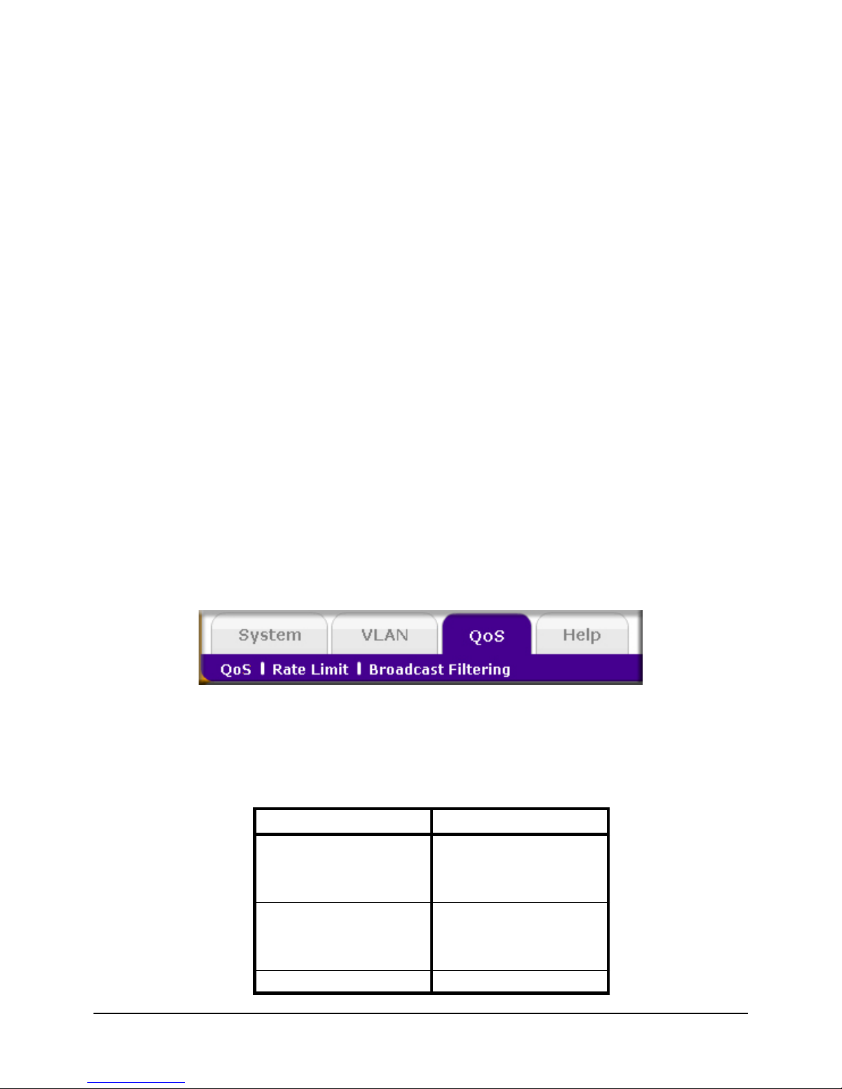
The QoS (Quality of Service) feature in the ProSafe® Plus switches allows you to control the flow of data
passing through the switch.
• QoS global configuration assigns priorities to data.
• Rate Limit sets limits on transmission rates for data passing through the switch.
• Broadcast Filtering blocks mass transmissions of broadcast packets from being forwarded to all ports.
All of the QoS features have default settings. It is not necessary to configure any settings in order to use the
ProSafe® Plus switches. The following table lists the default settings.
Table 4-1. QoS Default Settings
Feature Setting
Global Configuration
QoS Mode Port based
Port Priority Low priority for each port
Rate Limit
Ingress No limit
Egress No limit
Broadcast Filtering Disabled
Page 28
ProSafe® Plus Switch Configuration Utility User Guide
4-2 Quality of Service Configuration
v1.0, February 2010
QoS Global Configuration
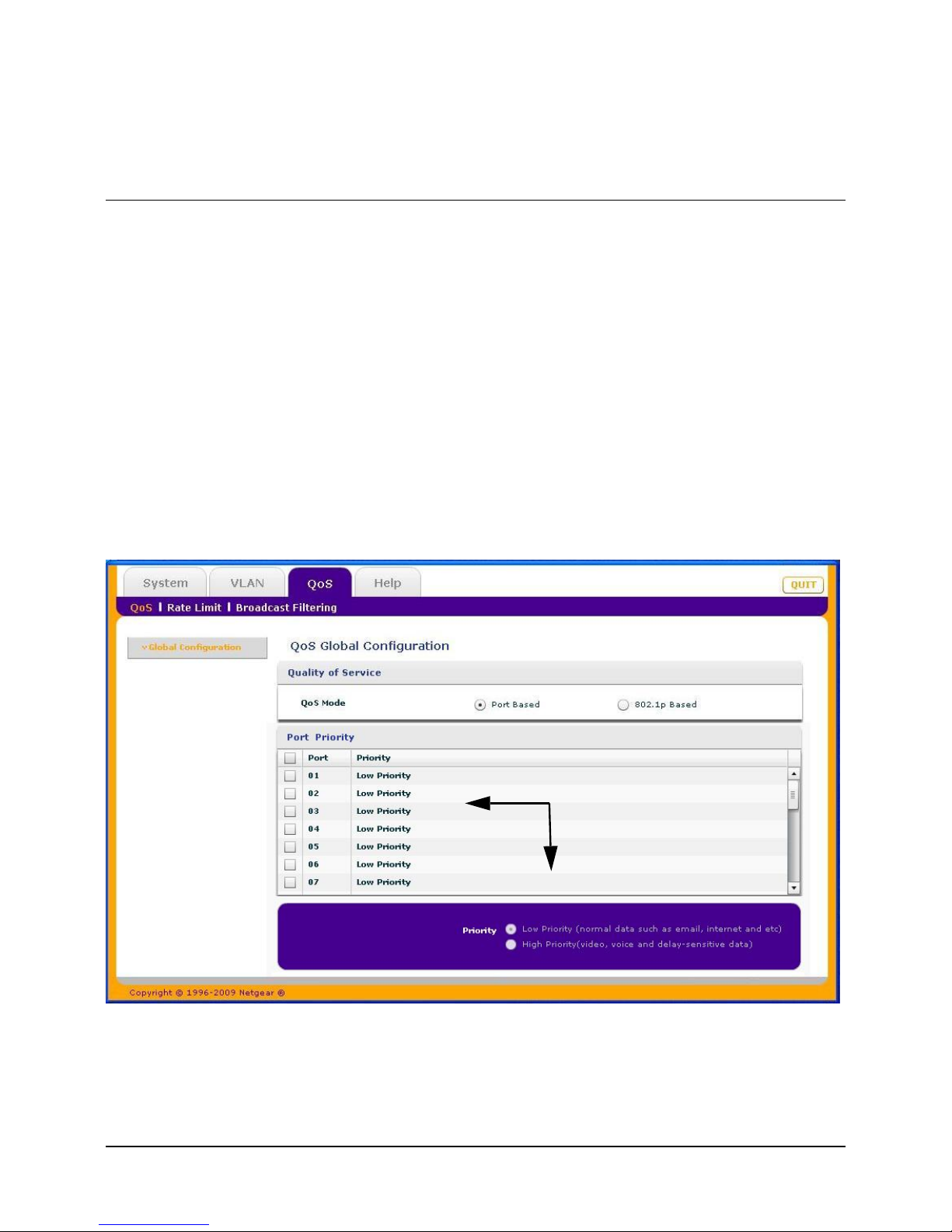
Global configuration allows you to assign priorities for how data will be transmitted by the switch. Priority
can be assigned either by port number (Port Based) or by the type of data being transmitted (802.1p based).
You would typically want to assign a low priority for normal classes of data (email, internet browsing, and
ordinary data transfers) and high priority to video, voice, and other delay sensitive data.
Port Based Priority
Port Based priority works by assigning a priority to all data passing through a particular port. A higher
priority will transmit data with a minimum of delays. If packets arrive at several ports at the same time, the
ports configured as higher priority will transmit their packets first. This means that you need to determine
which ports are going to carry delay sensitive data.
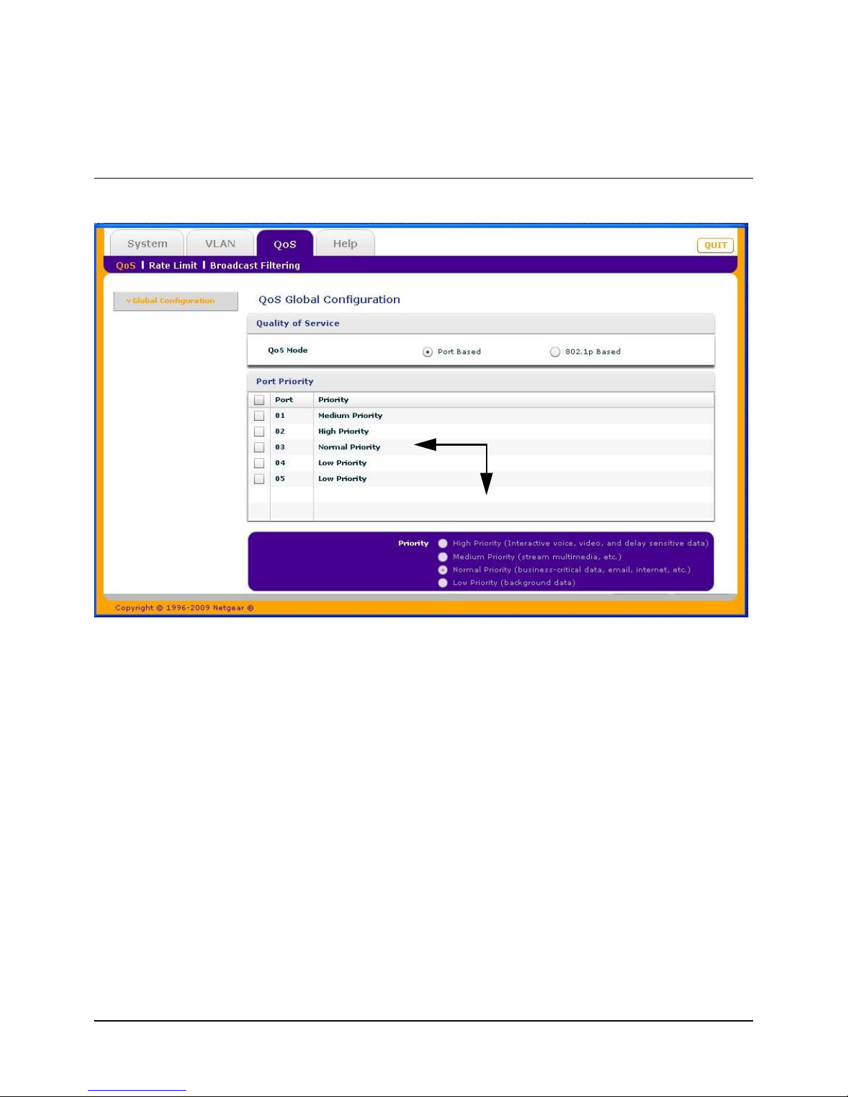
Some switches allow you to select between two priority levels (High and Low). Others allow four levels
(High, Medium, Normal, and Low).
2 priority levels
Page 29
ProSafe® Plus Switch Configuration Utility User Guide
Quality of Service Configuration 4-3
v1.0, February 2010
To assign Port Based priorities:
1. Select System and click on the radio button for the switch you want to configure.
2. Select QoS. The QoS Global Configuration screen displays.
3. Select the ports that you want to have that priority.
4. Select a priority level that you want to assign from the list at the bottom of the display.
5. Click Apply. The selected ports will be displayed with the new priority.
6. Repeat for the remaining ports.
802.1p Based Priority
802.1p Based priority uses a header in the data packet that identifies the class of data (for example, voice or
video) in the packet. When 802.1p based priority is used, the switch reads information in the packet header
to determine the priority to assign to the data packet. When 802.1p Based Priority is used, all ports on the
switch will check the packet header and transmit the packet according to its content.
To select 802.1p Based priority:
1. Select System and click on the radio button for the switch you want to configure.
2. Select QoS. The QoS Global Configuration screen displays.
4 priority levels
Page 30

ProSafe® Plus Switch Configuration Utility User Guide
4-4 Quality of Service Configuration
v1.0, February 2010
3. Select the 802.1p Based radio button. A message will display warning you that previous QoS settings
for the switch will be lost.
4. Click Yes. Data will now be processed based on 802.1p priority tags in the data.
Rate Limiting
You can limit the rate at which the switch accepts incoming data and the rate that it retransmits outgoing
data. you can set rate values. The choices for rates will vary depending on the switch model. Rate limiting
can be set for a port in addition to other QoS settings. If a port has a rate limit set, the switch will restrict the
acceptance or retransmission of data to the values configured.
To configure Rate Limiting:
1. Select System and click on the radio button for the switch you want to configure.
2. Select QoS > Rate Limit. The QoS Rate Limit screen displays.
3. Select one or more ports then select ingress and egress rates to assign.
4. Click Apply. The rates will be displayed opposite the selected ports.
5. Repeat for the remaining ports.
Broadcast Filtering
A switch can be configured to block massive transmission of broadcast packets being forwarded to every
port on the same VLAN. This is also known as broadcast storm protection. Failure to block broadcast storm
packets can cause a delay or halt to other data. Some switches allow you to select a Storm Control Rate for
each port, others assign a predetermined Storm control rate for all ports on the switch.
To configure Broadcast Filtering:
1. .Select System and click on the radio button for the switch you want to configure.
2. Select QoS > Broadcast Filtering. The QoS Broadcast Filtering screen displays.
3. Select Enable. If the selected switch supports configuring individual ports, a Storm control rate screen
will be displayed. If the selected switch does not support individual port configuration, all of the ports
will be set to a predetermined Storm control rate.
4. If the ports are configurable, select one or more ports and the desired Storm control rate. Click Apply.
Page 31
5-1
v1.0, February 2010
Chapter 5
Help
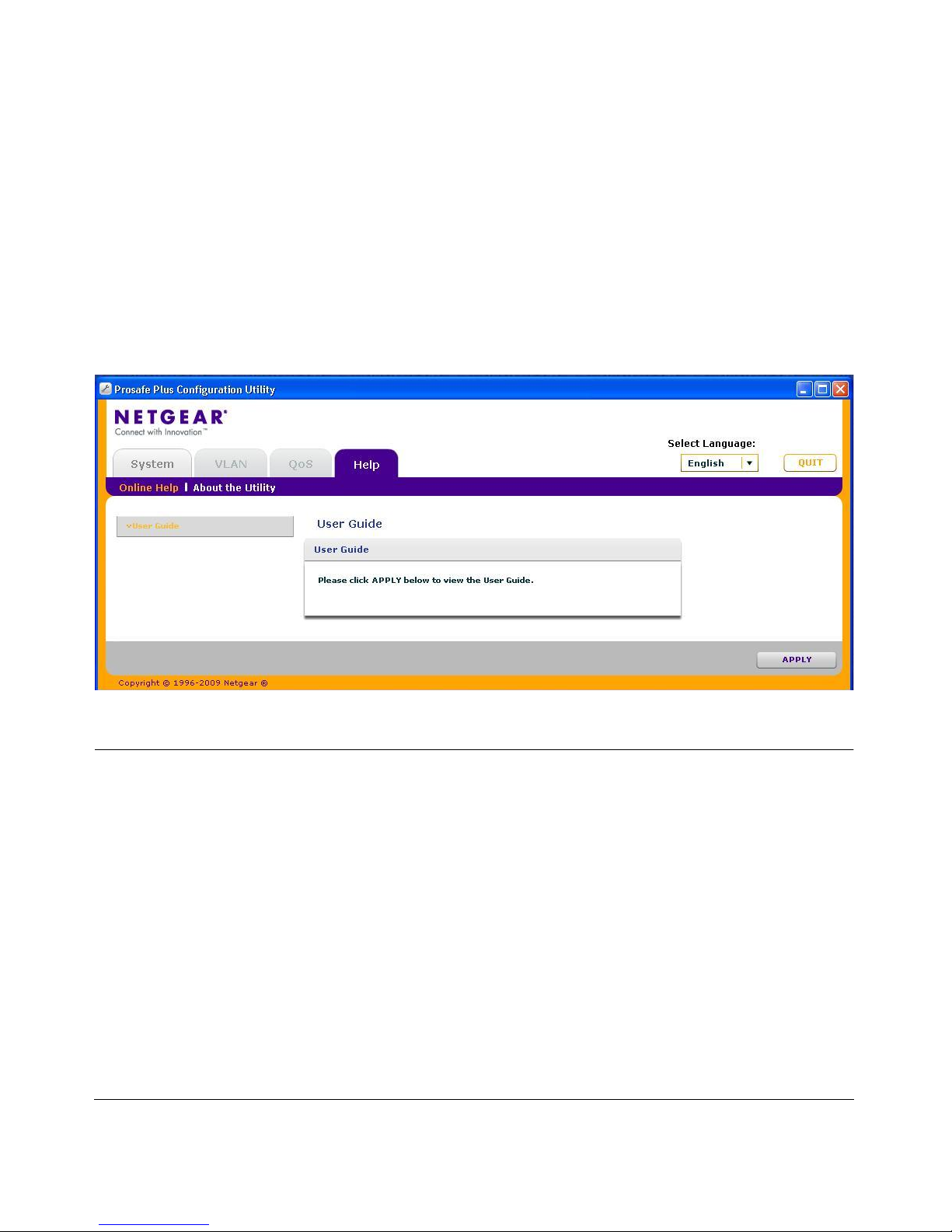
The Help tab provides access to the NETGEAR Support web site and to the online user guide for the
ProSafe® Plus Switch Configuration Utility (the latest copy of this manual).
Online Help
User Guide
If the PC running the utility program has access to the internet, selecting User Guide, then clicking Apply
will open the latest version of this user guide. You can then download a copy of the User Guide to your PC.
After installing a new ProSafe® Plus Switch you should check this website for the latest version of this
manual.
Support Information
If the PC running the utility program has access to the internet, you can display the support page for a
selected switch. Selecting Support, then clicking Apply will open a NETGEAR support page for the
selected switch model.
The support page provides access to the NETGEAR Knowledge Base, additional documentation,
downloads, and product forums for the selected product.
Page 32
ProSafe® Plus Switch Configuration Utility User Guide
5-2 Help
v1.0, February 2010
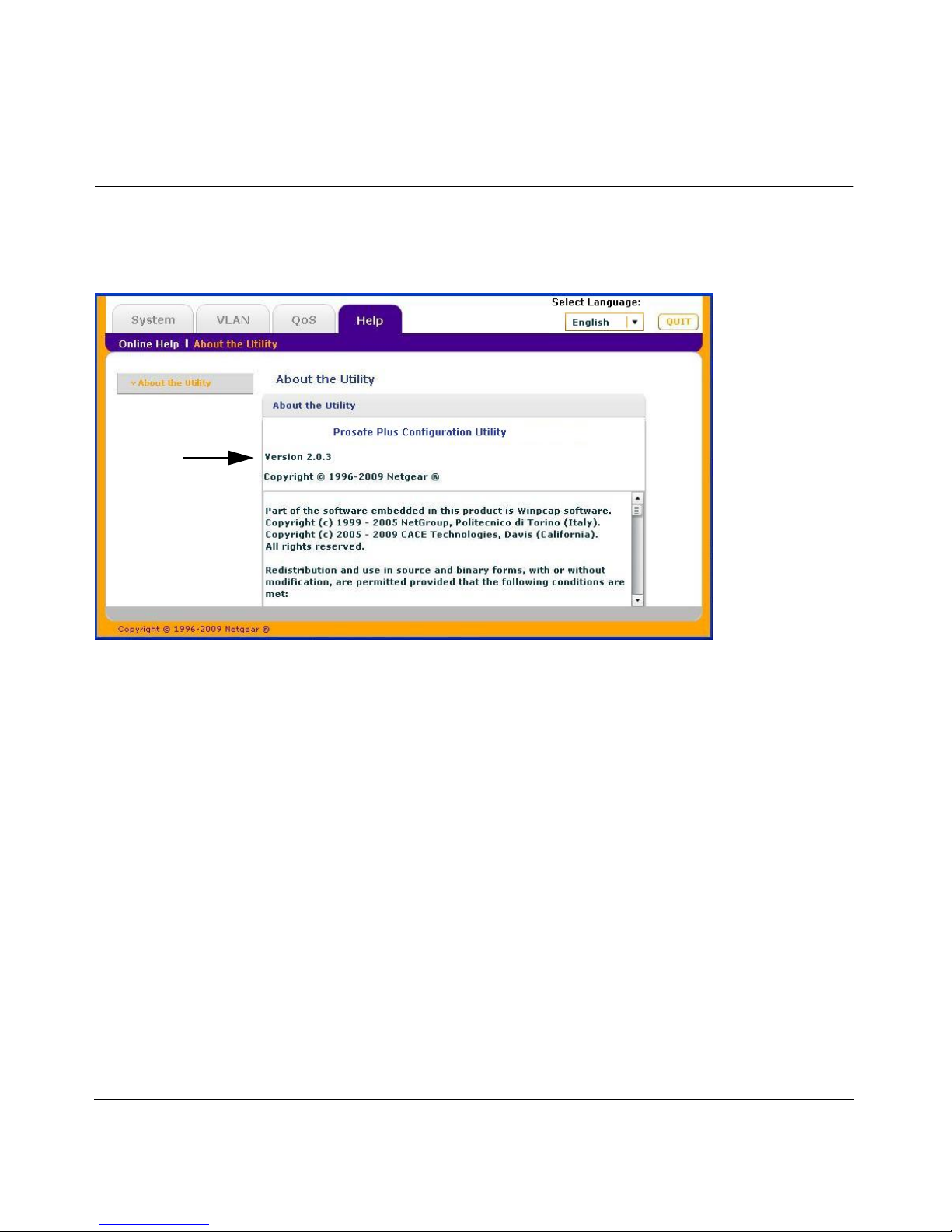
About the Utility
Selecting About the Utility on the Help tab displays the utility software version for the ProSafe® Plus
Configuration Utility.
Version
 Loading...