

Page 1

ProSafe 7300S Managed
Switches CLI Manual,
Version 8.0
NETGEAR, Inc.
350 East Plumeria Drive
San Jose, CA 95134
202-10528-01
July 2009
Page 2

© 2009 by NETGEAR, Inc. All rights reserved.
Trademarks
NETGEAR and the NETGEAR logo are registered trademarks, and ProSafe is a trademark of NETGEAR, Inc.
Microsoft, Windows, and Windows NT are registered trademarks of Microsoft Corporation.
Other brand and product names are registered trademarks or trademarks of their respective holders. Portions of this
document are copyright Intoto, Inc.
Statement of Conditions
In the interest of improving internal design, operational function, and/or reliability, NETGEAR reserves the right to
make changes to the products described in this document without notice.
NETGEAR does not assume any liability that may occur due to the use or application of the product(s) or circuit
layout(s) described herein.
EN 55 022 Declaration of Conformance
This is to certify that the ProSafe 7300S Series Layer-3 Managed Stackable Switch is shielded against the generation of
radio interference in accordance with the application of Council Directive 89/336/EEC, Article 4a. Conformity is
declared by the application of EN 55 022 Class B (CISPR 22).
Certificate of the Manufacturer/Importer
It is hereby certified that the ProSafe 7300S Series Layer-3 Managed Stackable Switch has been suppressed
in accordance with the conditions set out in the BMPT-AmtsblVfg 243/1991 and Vfg 46/1992. The operation of some
equipment (for example, test transmitters) in accordance with the regulations may, however, be subject to certain
restrictions. Please refer to the notes in the operating instructions.
The Federal Office for Telecommunications Approvals has been notified of the placing of this equipment on the market
and has been granted the right to test the series for compliance with the regulations.
Bestätigung des Herstellers/Importeurs
Es wird hiermit bestätigt, daß dasProSafe 7300S Series Layer-3 Managed Stackable Switch gemäß der im BMPTAmtsblVfg 243/1991 und Vfg 46/1992 aufgeführten Bestimmungen entstört ist. Das vorschriftsmäßige Betreiben
einiger Geräte (z.B. Testsender) kann jedoch gewissen Beschränkungen unterliegen. Lesen Sie dazu bitte die
Anmerkungen in der Betriebsanleitung.
Das Bundesamt für Zulassungen in der Telekommunikation wurde davon unterrichtet, daß dieses Gerät auf den Markt
gebracht wurde und es ist berechtigt, die Serie auf die Erfüllung der Vorschriften hin zu überprüfen.
Voluntary Control Council for Interference (VCCI) Statement
This equipment is in the Class B category (information equipment to be used in a residential area or an adjacent area
thereto) and conforms to the standards set by the Voluntary Control Council for Interference by Data Processing
Equipment and Electronic Office Machines aimed at preventing radio interference in such residential areas. When used
near a radio or TV receiver, it may become the cause of radio interference. Read instructions for correct handling.
v1.0, July 2009
ii
Page 3

Product and Publication Details
Model Number: GSM7328S, GSM7352S, GSM7328FS, GSM7328Sv2, and
GSM7352Sv2
Publication Date: July 2009
Product Family: managed switch
Product Name: ProSafe 7300S Series Layer-3 Managed Stackable Switch
Home or Business Product: Business
Language: English
Publication Part Number: 202-10528-01
Publication Version Number 1.0
v1.0, July 2009
iii
Page 4
About This Manual
This document describes command-line interface (CLI) commands you use to view and configure
7300S Series Stackable Switch software. You can access the CLI by using a direct connection to
the serial port or by using telnet or SSH over a remote network connection.
Note: This document contains both standalone and stacking commands.
Audience
This document is for system administrators who configure and operate switches using 7300S
Series Stackable Switch software. It provides an understanding of the configuration options of the
software.
This document assumes that the reader has an understanding of the software base and has read the
appropriate specification for the relevant networking device platform. It also assumes that the
reader has a basic knowledge of Ethernet and networking concepts.
About Managed Switch Software
The Managed Switch software has two purposes:
• Assist attached hardware in switching frames, based on Layer 2, 3, or 4 information contained
in the frames.
• Provide a complete device management portfolio to the network administrator.
v1.0, July 2009
ix
Page 5
7300S Managed Switches CLI Manual, Version 8.0
Scope
This manual covers the layer 3 managed switches (GSM7328S, GSM7352S, GSM7328FS,
GSM7328Sv2, and GSM7352Sv2). Some of the commands described in this manual can only be
used on GSM7328Sv2 and GSM7352Sv2 switches. These commands are noted in text.
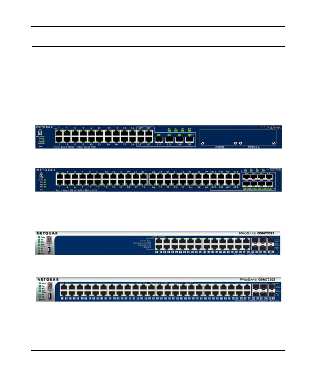
The following figure shows the GSM7328S and GSM7352S switches. Newer documentation
refers to these two switches as GSM7328Sv1 and GSM7352Sv1. Also shown are the
GSM7328Sv2 and GSM7352Sv2 switches.
Version 1 Switches
GSM7328Sv1
Version 2 Switches
GSM7352Sv1
GSM7328Sv2
GSM7352Sv2
x
v1.0, July 2009
Page 6
7300S Managed Switches CLI Manual, Version 8.0
Conventions and Formats
The conventions, formats, and scope of this manual are described in the following paragraphs:
• Typographical Conventions. This manual uses the following typographical conventions::
Italic Emphasis, books, CDs, file and server names, extensions
Bold User input, IP addresses, GUI screen text
Fixed Command prompt, CLI text, code
italic URL links
• Formats. This manual uses the following formats to highlight special messages:
Note: This format is used to highlight information of importance or special interest.
Tip: This format is used to highlight a procedure that will save time or resources.
Warning: Ignoring this type of note may result in a malfunction or damage to the
equipment.
Danger: This is a safety warning. Failure to take heed of this notice may result in
personal injury or death.
For more information about network, Internet, firewall, and VPN technologies, go to: http://
kbserver.netgear.com.
v1.0, July 2009
xi
Page 7

7300S Managed Switches CLI Manual, Version 8.0
How to Print This Manual
To print this manual, your computer must have the free Adobe Acrobat reader installed in order to
view and print PDF files. The Acrobat reader is available on the Adobe Web site at
http://www.adobe.com.
Revision History
Table 1-1.
Part Number
202-10528-01 1.0 July 2009 7300S Managed Switches CLI Manual, Version 8.0
Version
Number
Date Description
v1.0, July 2009
xii
Page 8

Contents
About This Manual
Audience ...........................................................................................................................xi
About Managed Switch Software ..................................................................................... xi
Scope ............................................................................................................................... xi
Chapter 1
Using the Command-Line Interface
Command Syntax ...........................................................................................................1-1
Command Conventions ..................................................................................................1-2
Common Parameter Values ...........................................................................................1-3
Unit/Slot/Port Naming Convention ..................................................................................1-3
Using the “No” Form of a Command ..............................................................................1-4
Managed Switch Modules ..............................................................................................1-5
Command Modes ...........................................................................................................1-5
Command Completion and Abbreviation ........................................................................1-9
CLI Error Messages ........................................................................................................1-9
CLI Line-Editing Conventions .......................................................................................1-10
Using CLI Help .............................................................................................................1-11
Accessing the CLI .........................................................................................................1-12
Chapter 2
Stacking Commands
Dedicated Port Stacking .................................................................................................2-1
Front Panel Stacking Commands .................................................................................2-10
Chapter 3
Switching Commands
Port Configuration Commands .......................................................................................3-2
Spanning Tree Protocol (STP) Commands ..................................................................3-11
VLAN Commands .........................................................................................................3-31
Double VLAN Commands ............................................................................................3-46
Voice VLAN Commands ...............................................................................................3-48
v1.0, July 2009
viii
Page 9

Managed Switch CLI Manual, Release 8.0
Provisioning (IEEE 802.1p) Commands .......................................................................3-51
Protected Ports Commands .........................................................................................3-52
Private Group Commands ............................................................................................3-54
GARP Commands ........................................................................................................3-56
GVRP Commands ........................................................................................................3-59
GMRP Commands .......................................................................................................3-61
Port-Based Network Access Control Commands .........................................................3-64
Storm-Control Commands ............................................................................................3-78
Port-Channel/LAG (802.3ad) Commands ....................................................................3-90
Port Mirroring ..............................................................................................................3-113
Static MAC Filtering ....................................................................................................3-115
DHCP Snooping Configuration Commands ...............................................................3-120
Dynamic ARP Inspection Commands ........................................................................3-131
IGMP Snooping Configuration Commands ................................................................3-139
IGMP Snooping Querier Commands ..........................................................................3-148
MLD Snooping Commands ........................................................................................3-153
MLD Snooping Querier Commands ...........................................................................3-162
Port Security Commands ............................................................................................3-166
LLDP (802.1AB) Commands ......................................................................................3-170
LLDP-MED Commands ..............................................................................................3-181
Denial of Service Commands .....................................................................................3-192
MAC Database Commands ........................................................................................3-204
ISDP Commands ........................................................................................................3-206
Chapter 4
Routing Commands
Address Resolution Protocol (ARP) Commands ............................................................4-1
IP Routing Commands ...................................................................................................4-8
Router Discovery Protocol Commands ........................................................................4-20
Virtual LAN Routing Commands................................................................................... 4-24
Virtual Router Redundancy Protocol Commands......................................................... 4-25
DHCP and BOOTP Relay Commands .........................................................................4-34
IP Helper Commands ...................................................................................................4-36
Open Shortest Path First (OSPF) Commands .............................................................4-39
Routing Information Protocol (RIP) Commands ...........................................................4-82
ICMP Throttling Commands .........................................................................................4-91
v1.0, July 2009
ix
Page 10

Managed Switch CLI Manual, Release 8.0
Chapter 5
IP Multicast Commands
Multicast Commands ......................................................................................................5-1
DVMRP Commands .......................................................................................................5-7
PIM-DM Commands .....................................................................................................5-12
PIM-SM Commands .....................................................................................................5-16
Internet Group Message Protocol (IGMP) Commands .................................................5-26
IGMP Proxy Commands ...............................................................................................5-35
Chapter 6
IPv6 Multicast Commands
IPv6 Multicast Forwarder ................................................................................................6-2
IPv6 PIM-DM Commands ...............................................................................................6-4
IPv6 PIM-SM Commands ...............................................................................................6-8
IPv6 MLD Commands ..................................................................................................6-16
IPv6 MLD-Proxy Commands ........................................................................................6-23
Chapter 7
IPv6 Commands
IPv6 Management Commands .......................................................................................7-2
Tunnel Interface Commands ..........................................................................................7-6
Loopback Interface Commands......................................................................................7- 8
IPv6 Routing Commands ..............................................................................................7-10
OSPFv3 Commands .....................................................................................................7-33
DHCPv6 Commands ....................................................................................................7-68
Chapter 8
Quality of Service (QoS) Commands
Class of Service (CoS) Commands ................................................................................8-2
Differentiated Services (DiffServ) Commands ................................................................8-8
DiffServ Class Commands ...........................................................................................8-10
DiffServ Policy Commands ...........................................................................................8-19
DiffServ Service Commands ........................................................................................8-25
DiffServ Show Commands ...........................................................................................8-26
MAC Access Control List (ACL) Commands ................................................................8-32
IP Access Control List (ACL) Commands .....................................................................8-37
IPv6 Access Control List (ACL) Commands .................................................................8-44
Auto-Voice over IP Commands ....................................................................................8-48
v1.0, July 2009
x
Page 11

Managed Switch CLI Manual, Release 8.0
Chapter 9
Utility Commands
Auto Install Commands ..................................................................................................9-2
Dual Image Commands ..................................................................................................9-4
System Information and Statistics Commands ...............................................................9-6
Logging Commands .....................................................................................................9-18
System Utility and Clear Commands ............................................................................9-24
Simple Network Time Protocol (SNTP) Commands .....................................................9-34
DHCP Server Commands ............................................................................................9-40
DNS Client Commands ................................................................................................9-55
Packet Capture Commands .........................................................................................9-61
Serviceability Packet Tracing Commands ....................................................................9-63
Cable Test Command................................................................................................... 9-83
sFlow Commands......................................................................................................... 9-84
Chapter 10
Management Commands
Configuring the Switch Management CPU ...................................................................11-2
Network Interface Commands ......................................................................................11-4
Console Port Access Commands .................................................................................11-8
Telnet Commands ......................................................................................................11-11
Secure Shell (SSH) Commands .................................................................................11-16
Management Security Commands .............................................................................11-19
Hypertext Transfer Protocol (HTTP) Commands .......................................................11-20
Access Commands .....................................................................................................11-28
User Account Commands ...........................................................................................11-29
SNMP Commands ......................................................................................................11-40
RADIUS Commands ...................................................................................................11-52
TACACS+ Commands ................................................................................................11-67
Configuration Scripting Commands ............................................................................11-71
Pre-login Banner and System Prompt Commands .....................................................11-73
Chapter 11
Log Messages
Core ..............................................................................................................................11-1
Utilities ..........................................................................................................................11-4
Management .................................................................................................................11-6
v1.0, July 2009
xi
Page 12

Managed Switch CLI Manual, Release 8.0
Switching ....................................................................................................................11-10
QoS ............................................................................................................................11-16
Routing/IPv6 Routing ..................................................................................................11-17
Multicast .....................................................................................................................11-21
Stacking ......................................................................................................................11-23
Technologies ..............................................................................................................11-23
O/S Support ................................................................................................................11-26
Chapter 12
Captive Portal Commands
Capitve Portal Global Commands ................................................................................12-1
Captive Portal Configuration Commands .....................................................................12-5
Captive Portal Status Commands ..............................................................................12-14
Captive Portal Client Connection Commands ............................................................12-19
Captive Portal Interface Commands ...........................................................................12-23
Captive Portal Local User Commands .......................................................................12-24
Captive Portal User Group Commands ......................................................................12-31
Chapter 13
List of Commands
v1.0, July 2009
xii
Page 13

Chapter 1
Using the Command-Line Interface
The command-line interface (CLI) is a text-based way to manage and monitor the system. You can
access the CLI by using a direct serial connection or by using a remote logical connection with
telnet or SSH.
This chapter describes the CLI syntax, conventions, and modes. It contains the following sections:
• “Command Syntax” on page 1-1
• “Command Conventions” on page 1-2
• “Common Parameter Values” on page 1-3
• “Unit/Slot/Port Naming Convention” on page 1-3
• “Using the “No” Form of a Command” on page 1-4
• “Managed Switch Modules” on page 1-5
• “Command Modes” on page 1-5
• “Command Completion and Abbreviation” on page 1-9
• “CLI Error Messages” on page 1-9
• “CLI Line-Editing Conventions” on page 1-10
• “Using CLI Help” on page 1-11
• “Accessing the CLI” on page 1-12
Command Syntax
A command is one or more words that might be followed by one or more parameters. Parameters
can be required or optional values.
Some commands, such as show network or clear vlan, do not require parameters. Other
commands, such as network parms, require that you supply a value after the command. You
must type the parameter values in a specific order, and optional parameters follow required
parameters. The following example describes the network parms command syntax:
Format network parms <ipaddr> <netmask> [gateway]
1-1
v1.0, July 2009
Page 14

Managed Switch CLI Manual, Release 8.0
• network parms is the command name.
• <ipaddr> and <netmask> are parameters and represent required values that you must
enter after you type the command keywords.
• [gateway] is an optional parameter, so you are not required to enter a value in place of the parameter.
The CLI Command Reference lists each command by the command name and provides a brief
description of the command. Each command reference also contains the following information:
• Format shows the command keywords and the required and optional parameters.
• Mode identifies the command mode you must be in to access the command.
• Default shows the default value, if any, of a configurable setting on the device.
The show commands also contain a description of the information that the command shows.
Command Conventions
In this document, the command name is in bold font. Parameters are in italic font. You
must replace the parameter name with an appropriate value, which might be a name or number.
Parameters are order dependent.
The parameters for a command might include mandatory values, optional values, or keyword
choices. Table 1 describes the conventions this document uses to distinguish between value types.
Table 1. Parameter Conventions
Symbol Example Description
<> angle brackets <value> Indicates that you must enter a value in place of the
brackets and text inside them.
[] square brackets [value] Indicates an optional parameter that you can enter in
place of the brackets and text inside them.
{} curly braces {choice1 |
choice2}
| Vertical bars choice1 | choice2 Separates the mutually exclusive choices.
[{}] Braces within
square brackets
[{choice1 |
choice2}]
Using the Command-Line Interface 1-2
Indicates that you must select a parameter from the list of
choices.
Indicates a choice within an optional element.
v1.0, July 2009
Page 15

Managed Switch CLI Manual, Release 8.0
Common Parameter Values
Parameter values might be names (strings) or numbers.To use spaces as part of a name parameter,
enclose the name value in double quotes. For example, the expression “System Name with
Spaces” forces the system to accept the spaces. Empty strings (““) are not valid user-defined
strings. Table 2 describes common parameter values and value formatting.
Table 2. Parameter Descriptions
Parameter Description
ipaddr This parameter is a valid IP address. You can enter the IP address in the following
formats:
a (32 bits)
a.b (8.24 bits)
a.b.c (8.8.16 bits)
a.b.c.d (8.8.8.8)
In addition to these formats, the CLI accepts decimal, hexadecimal and octal formats
through the following input formats (where n is any valid hexadecimal, octal or decimal
number):
0xn (CLI assumes hexadecimal format)
0n (CLI assumes octal format with leading zeros)
n (CLI assumes decimal format)
ipv6-address FE80:0000:0000:0000:020F:24FF:FEBF:DBCB, or
FE80:0:0:0:20F:24FF:FEBF:DBCB, or
FE80::20F24FF:FEBF:DBCB, or
FE80:0:0:0:20F:24FF:128:141:49:32
For additional information, refer to RFC 3513.
Interface or
unit/slot/port
Logical Interface Represents a logical slot and port number. This is applicable in the case of a port-
Character strings Use double quotation marks to identify character strings, for example, “System Name
Valid unit, slot, and port number separated by forward slashes. For example, 0/1
represents slot number 0 and port number 1.
channel (LAG). You can use the logical unit/slot/port to configure the port-channel.
with Spaces”. An empty string (“”) is not valid.
Unit/Slot/Port Naming Convention
Managed switch software references physical entities such as cards and ports by using a unit/slot/
port naming convention. The software also uses this convention to identify certain logical entities,
such as Port-Channel interfaces.
Using the Command-Line Interface 1-3
v1.0, July 2009
Page 16
Managed Switch CLI Manual, Release 8.0
The slot number has two uses. In the case of physical ports, it identifies the card containing the
ports. In the case of logical and CPU ports it also identifies the type of interface or port.
Table 3. Type of Slots
Slot Type Description
Physical slot numbers Physical slot numbers begin with zero, and are allocated up to the maximum
number of physical slots.
Logical slot numbers Logical slots immediately follow physical slots and identify port-channel (LAG) or
router interfaces.
CPU slot numbers The CPU slots immediately follow the logical slots.
The port identifies the specific physical port or logical interface being managed on a given slot.
Table 4. Type of Ports
Port Type Description
Physical Ports The physical ports for each slot are numbered sequentially starting from zero.
Logical Interfaces Port-channel or Link Aggregation Group (LAG) interfaces are logical interfaces
that are only used for bridging functions.
VLAN routing interfaces are only used for routing functions.
Loopback interfaces are logical interfaces that are always up.
Tunnel interfaces are logical point-to-point links that carry encapsulated packets.
CPU ports CPU ports are handled by the driver as one or more physical entities located on
physical slots.
Note: In the CLI, loopback and tunnel interfaces do not use the unit/slot/port format. To
specify a loopback interface, you use the loopback ID. To specify a tunnel
interface, you use the tunnel ID.
Using the “No” Form of a Command
The no keyword is a specific form of an existing command and does not represent a new or
distinct command. Almost every configuration command has a no form. In general, use the no
form to reverse the action of a command or reset a value back to the default. For example, the no
Using the Command-Line Interface 1-4
v1.0, July 2009
Page 17

Managed Switch CLI Manual, Release 8.0
shutdown configuration command reverses the shutdown of an interface. Use the command
without the keyword no to re-enable a disabled feature or to enable a feature that is disabled by
default. Only the configuration commands are available in the no form.
Managed Switch Modules
Managed switch software consists of flexible modules that can be applied in various combinations
to develop advanced Layer 2/3/4+ products. The commands and command modes available on
your switch depend on the installed modules. Additionally, for some show commands, the output
fields might change based on the modules included in the software.
The software suite includes the following modules:
• Switching (Layer 2)
• Routing (Layer 3)
• IPv6—IPv6 routing
• Multicast
• Quality of Service
• Management (CLI, Web UI, and SNMP)
• IPv6 Management—Allows management of the device through an IPv6 through an IPv6
address without requiring the IPv6 Routing package in the system. The management address
can be associated with the network port (front-panel switch ports), a routine interface (port or
VLAN) and the Service port.
• Stacking
Not all modules are available for all platforms or software releases.
Command Modes
The CLI groups commands into modes according to the command function. Each of the command
modes supports specific software commands. The commands in one mode are not available until
you switch to that particular mode, with the exception of the User EXEC mode commands. You
can execute the User EXEC mode commands in the Privileged EXEC mode.
Using the Command-Line Interface 1-5
v1.0, July 2009
Page 18
Managed Switch CLI Manual, Release 8.0
The command prompt changes in each command mode to help you identify the current mode.
Table 5 describes the command modes and the prompts visible in that mode.
Note: The command modes available on your switch depend on the software modules
that are installed. For example, a switch that does not support BGPv4 does not have
the Router BGPv4 Command Mode.
Table 5. CLI Command Modes
Command Mode Prompt Mode Description
User EXEC Switch> Contains a limited set of commands to view
basic system information.
Privileged EXEC Switch# Allows you to issue any EXEC command, enter
the VLAN mode, or enter the Global
Configuration mode.
Global Config Switch (Config)# Groups general setup commands and permits
you to make modifications to the running
configuration.
VLAN Config Switch (Vlan)# Groups all the VLAN commands.
Interface Config Switch (Interface <unit/slot/port>)#
Switch (Interface Loopback <id>)#
Switch (Interface Tunnel <id>)#
Line Config Switch (line)# Contains commands to configure outbound
Policy Map
Config
Policy Class
Config
Class Map Config Switch (Config-class-map)# Contains the QoS class map configuration
Ipv6_Class-Map
Config
Router OSPF
Config
Switch (Config-policy-map)# Contains the QoS Policy-Map configuration
Switch (Config-policy-class-map)# Consists of class creation, deletion, and
Switch (Config-class-map)# Contains the QoS class map configuration
Switch (Config-router)# Contains the OSPF configuration commands.
Manages the operation of an interface and
provides access to the router interface
configuration commands.
Use this mode to set up a physical port for a
specific logical connection operation.
telnet settings and console interface settings.
commands.
matching commands. The class match
commands specify Layer 2, Layer 3, and
general match criteria.
commands for IPv4.
commands for IPv6.
Using the Command-Line Interface 1-6
v1.0, July 2009
Page 19

Managed Switch CLI Manual, Release 8.0
Table 5. CLI Command Modes (continued)
Command Mode Prompt Mode Description
Router OSPFv3
Config
Router RIP Config Switch (Config-router)# Contains the RIP configuration commands.
Router BGP
Config
MAC Access-list
Config
TACACS Config Switch (Tacacs)# Contains commands to configure properties for
DHCP Pool
Config
DHCPv6 Pool
Config
Stack Global
Config Mode
ARP Access-List
Config Mode
Switch (Config rtr)# Contains the OSPFv3 configuration commands.
Switch (Config-router)# Contains the BGP4 configuration commands.
Switch (Config-mac-access-list)# Allows you to create a MAC Access-List and to
enter the mode containing MAC Access-List
configuration commands.
the TACACS servers.
Switch (Config dhcp-pool)# Contains the DHCP server IP address pool
configuration commands.
Switch (Config dhcp6-pool)# Contains the DHCPv6 server IPv6 address pool
configuration commands.
Switch (Config stack)# Allows you to access the Stack Global Config
Mode.
Switch (Config-arp-access-list)# Contains commands to add ARP ACL rules in
an ARP Access List.
Table 6 explains how to enter or exit each mode.
Table 6. CLI Mode Access and Exit
Command Mode Access Method Exit or Access Previous Mode
User EXEC This is the first level of access. To exit, enter logout.
Privileged EXEC From the User EXEC mode, enter
enable.
Global Config From the Privileged EXEC mode,
enter configure.
VLAN Config From the Privileged EXEC mode,
enter vlan database.
Interface Config From the Global Config mode,
enter
interface <unit/slot/port>
or interface loopback <id>
or interface tunnel <id>
To exit to the User EXEC mode, enter exit or
press Ctrl-Z.
To exit to the Privileged EXEC mode, enter exit,
or press Ctrl-Z.
To exit to the Privileged EXEC mode, enter exit,
or press Ctrl-Z.
To exit to the Global Config mode, enter exit. To
return to the Privileged EXEC mode, enter Ctrl-
Z.
Using the Command-Line Interface 1-7
v1.0, July 2009
Page 20

Managed Switch CLI Manual, Release 8.0
Table 6. CLI Mode Access and Exit (continued)
Command Mode Access Method Exit or Access Previous Mode
Line Config From the Global Config mode,
enter
lineconfig.
Policy-Map
Config
Policy-Class-Map
Config
Class-Map
Config
Ipv6-Class-Map
Config
Router OSPF
Config
Router OSPFv3
Config
Router RIP
Config
Router BGP
Config
MAC Access-list
Config
From the Global Config mode,
enter
policy-map <name> in.
From the Policy Map mode enter
class.
From the Global Config mode,
enter
class-map, and specify the
optional keyword ipv4 to specify
the Layer 3 protocol for this class.
See “class-map” on page 8-10 for
more information.
From the Global Config mode,
enter
class-map and specify the
optional keyword ipv6 to specify
the Layer 3 protocol for this class.
See “class-map” on page 8-10 for
more information.
From the Global Config mode,
enter
router ospf.
From the Global Config mode,
enter
ipv6 router ospf.
From the Global Config mode,
enter
router rip.
From the Global Config mode,
enter
router bgp <asnumber>.
From the Global Config mode,
enter
mac access-list extended
<name>.
To exit to the Global Config mode, enter exit. To
return to the Privileged EXEC mode, enter Ctrl-
Z.
To exit to the Global Config mode, enter exit. To
return to the Privileged EXEC mode, enter Ctrl-
Z.
To exit to the Policy Map mode, enter exit. To
return to the Privileged EXEC mode, enter Ctrl-
Z.
To exit to the Global Config mode, enter exit. To
return to the Privileged EXEC mode, enter Ctrl-
Z.
To exit to the Global Config mode, enter exit. To
return to the Privileged EXEC mode, enter Ctrl-
Z.
To exit to the Global Config mode, enter exit. To
return to the Privileged EXEC mode, enter Ctrl-
Z.
To exit to the Global Config mode, enter exit. To
return to the Privileged EXEC mode, enter Ctrl-
Z.
To exit to the Global Config mode, enter exit. To
return to the Privileged EXEC mode, enter Ctrl-
Z.
To exit to the Global Config mode, enter exit. To
return to the Privileged EXEC mode, enter Ctrl-
Z.
To exit to the Global Config mode, enter exit. To
return to the Privileged EXEC mode, enter Ctrl-
Z.
Using the Command-Line Interface 1-8
v1.0, July 2009
Page 21

Managed Switch CLI Manual, Release 8.0
Table 6. CLI Mode Access and Exit (continued)
Command Mode Access Method Exit or Access Previous Mode
TACACS Config From the Global Config mode,
enter tacacs-server host
<ip-addr>, where <ip-addr> is
the IP address of the TACACS
server on your network.
DHCP Pool
Config
DHCPv6 Pool
Config
Stack Global
Config Mode
ARP Access-List
Config Mode
From the Global Config mode,
enter
ip dhcp pool <pool-name>.
From the Global Config mode,
enter
ip dhcpv6 pool <pool-name>.
From the Global Config mode,
enter the stack command.
From the Global Config mode,
enter the arp access-list
command.
To exit to the Global Config mode, enter exit. To
return to the Privileged EXEC mode, enter Ctrl-
Z.
To exit to the Global Config mode, enter exit. To
return to the Privileged EXEC mode, enter Ctrl-
Z.
To exit to the Global Config mode, enter exit. To
return to the Privileged EXEC mode, enter Ctrl-
Z.
To exit to the Global Config mode, enter the exit
command. To return to the Privileged EXEC
mode, enter Ctrl-Z.
To exit to the Global Config mode, enter the
exit command. To return to the Privileged
EXEC mode, enter Ctrl-Z.
Command Completion and Abbreviation
Command completion finishes spelling the command when you type enough letters of a command
to uniquely identify the command keyword. Once you have entered enough letters, press the
SPACEBAR or TAB key to complete the word.
Command abbreviation allows you to execute a command when you have entered there are enough
letters to uniquely identify the command. You must enter all of the required keywords and
parameters before you enter the command.
CLI Error Messages
If you enter a command and the system is unable to execute it, an error message appears. Table 7
describes the most common CLI error messages.
Using the Command-Line Interface 1-9
v1.0, July 2009
Page 22

Managed Switch CLI Manual, Release 8.0
Table 7. CLI Error Messages
Message Text Description
% Invalid input detected at '^' marker. Indicates that you entered an incorrect or unavailable command.
The carat (^) shows where the invalid text is detected. This
message also appears if any of the parameters or values are not
recognized.
Command not found / Incomplete
command. Use ? to list commands.
Ambiguous command Indicates that you did not enter enough letters to uniquely identify
Indicates that you did not enter the required keywords or values.
the command.
CLI Line-Editing Conventions
Table 8 describes the key combinations you can use to edit commands or increase the speed of
command entry. You can access this list from the CLI by entering help from the User or
Privileged EXEC modes.
Table 8. CLI Editing Conventions
Key Sequence Description
DEL or Backspace Delete previous character
Ctrl-A Go to beginning of line
Ctrl-E Go to end of line
Ctrl-F Go forward one character
Ctrl-B Go backward one character
Ctrl-D Delete current character
Ctrl-U, X Delete to beginning of line
Ctrl-K Delete to end of line
Ctrl-W Delete previous word
Ctrl-T Transpose previous character
Ctrl-P Go to previous line in history buffer
Ctrl-R Rewrites or pastes the line
Ctrl-N Go to next line in history buffer
Ctrl-Y Prints last deleted character
Using the Command-Line Interface 1-10
v1.0, July 2009
Page 23

Managed Switch CLI Manual, Release 8.0
Table 8. CLI Editing Conventions (continued)
Key Sequence Description
Ctrl-Q Enables serial flow
Ctrl-S Disables serial flow
Ctrl-Z Return to root command prompt
Tab, <SPACE> Command-line completion
Exit Go to next lower command prompt
? List available commands, keywords, or parameters
Using CLI Help
Enter a question mark (?) at the command prompt to display the commands available in the current
mode.
(switch) >?
enable Enter into user privilege mode.
help Display help for various special keys.
logout Exit this session. Any unsaved changes are lost.
ping Send ICMP echo packets to a specified IP address.
quit Exit this session. Any unsaved changes are lost.
show Display Switch Options and Settings.
telnet Telnet to a remote host.
Enter a question mark (?) after each word you enter to display available command keywords or
parameters.
(switch) #network ?
javamode Enable/Disable.
mgmt_vlan Configure the Management VLAN ID of the switch.
parms Configure Network Parameters of the router.
protocol Select DHCP, BootP, or None as the network config
protocol.
If the help output shows a parameter in angle brackets, you must replace the parameter with a
value.
(switch) #network parms ?
<ipaddr> Enter the IP address.
Using the Command-Line Interface 1-11
v1.0, July 2009
Page 24

Managed Switch CLI Manual, Release 8.0
If there are no additional command keywords or parameters, or if additional parameters are
optional, the following message appears in the output:
<cr> Press Enter to execute the command
You can also enter a question mark (?) after typing one or more characters of a word to list the
available command or parameters that begin with the letters, as shown in the following example:
(switch) #show m?
mac-addr-table mac-address-table monitor
Accessing the CLI
You can access the CLI by using a direct console connection or by using a telnet or SSH
connection from a remote management host.
For the initial connection, you must use a direct connection to the console port. You cannot access
the system remotely until the system has an IP address, subnet mask, and default gateway. You can
set the network configuration information manually, or you can configure the system to accept
these settings from a BOOTP or DHCP server on your network. For more information, see
“Network Interface Commands” on page 10-4.
Using the Command-Line Interface 1-12
v1.0, July 2009
Page 25
Stacking Commands
The Stacking Commands chapter includes the following sections:
• “Dedicated Port Stacking” on page 2-1
• “Front Panel Stacking Commands” on page 2-10
Note: The commands in this chapter are in one of two functional groups:
Note: Show commands display switch settings, statistics, and other information.
Note: Configuration commands configure features and options of the switch. For
every configuration command, there is a show command that displays the
configuration setting.
The Primary Management Unit is the unit that controls the stack.
Chapter 2
Dedicated Port Stacking
This section describes the commands you use to configure dedicated port stacking.
stack
This command sets the mode to Stack Global Config.
Format stack
Mode Global Config
v1.0, July 2009
2-1
Page 26
Managed Switch CLI Manual, Release 8.0
member
This command configures a switch. The <unit> is the switch identifier of the switch to be
added/removed from the stack. The <switchindex> is the index into the database of the
supported switch types, indicating the type of the switch being preconfigured. The switch index is
a 32-bit integer. This command is executed on the Primary Management Unit.
Format member <unit> <switchindex>
Mode Stack Global Config
Note: Switch index can be obtained by executing the show supported switchtype
command in User EXEC mode.
no member
This command removes a switch from the stack. The <unit> is the switch identifier of the
switch to be removed from the stack. This command is executed on the Primary Management Unit.
Format no member <unit>
Mode Stack Global Config
switch priority
This command configures the ability of a switch to become the Primary Management Unit. The
<unit> is the switch identifier. The <value> is the preference parameter that allows the user
to specify, priority of one backup switch over another. The range for priority is 1 to 15. The switch
with the highest priority value will be chosen to become the Primary Management Unit if the
active Primary Management Unit fails. The switch priority defaults to the hardware management
preference value 1. Switches that do not have the hardware capability to become the Primary
Management Unit are not eligible for management.
Default enabled
Format switch <unit> priority <value>
Mode Global Config
Stacking Commands 2-2
v1.0, July 2009
Page 27
Managed Switch CLI Manual, Release 8.0
switch renumber
This command changes the switch identifier for a switch in the stack. The <oldunit> is the
current switch identifier on the switch whose identifier is to be changed. The <newunit> is the
updated value of the switch identifier. Upon execution, the switch will be configured with the
configuration information for the new switch, if any. The old switch configuration information will
be retained, however the old switch will be operationally unplugged. This command is executed on
the Primary Management Unit.
Note: If the management unit is renumbered, then the running configuration is no longer
applied (i.e. the stack acts as if the configuration had been cleared)
Format switch <oldunit> renumber <newunit>
Mode Global Config
movemanagement
This command moves the Primary Management Unit functionality from one switch to another.
The <fromunit> is the switch identifier on the current Primary Management Unit. The
<tounit> is the switch identifier on the new Primary Management Unit. Upon execution, the
entire stack (including all interfaces in the stack) is unconfigured and reconfigured with the
configuration on the new Primary Management Unit. After the reload is complete, all stack
management capability must be performed on the new Primary Management Unit. To preserve the
current configuration across a stack move, execute the copy system:running-config
nvram:startup-config (in Privileged EXEC) command before performing the stack move.
A stack move causes all routes and layer 2 addresses to be lost. This command is executed on the
Primary Management Unit. The system prompts you to confirm the management move.
Format movemanagement <fromunit> <tounit>
Mode Stack Global Config
Stacking Commands 2-3
v1.0, July 2009
Page 28
Managed Switch CLI Manual, Release 8.0
slot
This command configures a slot in the system. The <unit/slot> is the slot identifier of the
slot. The <cardindex> is the index into the database of the supported card types, indicating the
type of the card being preconfigured in the specified slot. The card index is a 32-bit integer. If a
card is currently present in the slot that is unconfigured, the configured information will be deleted
and the slot will be re-configured with default information for the card.
Format slot <unit/slot> <cardindex>
Mode Global Config
Note: Card index can be obtained by executing show supported cardtype command in
User EXEC mode.
no slot
This command removes configured information from an existing slot in the system.
Format no slot <unit/slot> <cardindex>
Mode Global Config
Note: Card index can be obtained by executing show supported cardtype command in
User EXEC mode.
set slot disable
This command configures the administrative mode of the slot(s). If you specify [all], the
command is applied to all slots, otherwise the command is applied to the slot identified by
<unit/slot>.
Stacking Commands 2-4
v1.0, July 2009
Page 29

Managed Switch CLI Manual, Release 8.0
If a card or other module is present in the slot, this administrative mode will effectively be applied
to the contents of the slot. If the slot is empty, this administrative mode will be applied to any
module that is inserted into the slot. If a card is disabled, all the ports on the device are
operationally disabled and shown as “unplugged” on management screens.
Format set slot disable [<unit/slot> | all]
Mode Global Config
no set slot disable
This command unconfigures the administrative mode of the slot(s). If you specify [all], the
command removes the configuration from all slots, otherwise the configuration is removed from
the slot identified by <unit/slot>.
If a card or other module is present in the slot, this administrative mode removes the configuration
from the contents of the slot. If the slot is empty, this administrative mode removes the
configuration from any module inserted into the slot. If a card is disabled, all the ports on the
device are operationally disabled and shown as “unplugged” on management screens.
Format no set slot disable [<unit/slot> | all]
Mode Global Config
set slot power
This command configures the power mode of the slot(s) and allows power to be supplied to a card
located in the slot. If you specify [all], the command is applied to all slots, otherwise the
command is applied to the slot identified by <unit/slot>.
Use this command when installing or removing cards. If a card or other module is present in this
slot, the power mode is applied to the contents of the slot. If the slot is empty, the power mode is
applied to any card inserted into the slot.
Format set slot power [<unit/slot> | all]
Mode Global Config
Stacking Commands 2-5
v1.0, July 2009
Page 30

Managed Switch CLI Manual, Release 8.0
no set slot power
This command unconfigures the power mode of the slot(s) and prohibits power from being
supplied to a card located in the slot. If you specify [all], the command prohibits power to all
slots, otherwise the command prohibits power to the slot identified by <unit/slot>.
Use this command when installing or removing cards. If a card or other module is present in this
slot, power is prohibited to the contents of the slot. If the slot is empty, power is prohibited to any
card inserted into the slot.
Format no set slot power [<unit/slot> | all]
Mode Global Config
reload (Stack)
This command resets the entire stack or the identified <unit>. The <unit> is the switch
identifier. The system prompts you to confirm that you want to reset the switch.
Format reload [<unit>]
Mode User EXEC
show slot
This command displays information about all the slots in the system or for a specific slot.
Format show slot [<unit/slot>]
Mode User EXEC
Term Definition
Slot The slot identifier in a <unit/slot> format.
Slot Status The slot is empty, full, or has encountered an error
Admin State The slot administrative mode is enabled or disabled.
Power State The slot power mode is enabled or disabled.
Configured Card
Model Identifier
Stacking Commands 2-6
The model identifier of the card preconfigured in the slot. Model Identifier is a 32character field used to identify a card.
v1.0, July 2009
Page 31

Managed Switch CLI Manual, Release 8.0
Term Definition
Pluggable Cards are pluggable or non-pluggable in the slot.
Power Down Indicates whether the slot can be powered down.
If you supply a value for <unit/slot>, the following additional information appears:
Term Definition
Inserted Card
Model Identifier
Inserted Card
Description
Configured Card
Description
The model identifier of the card inserted in the slot. Model Identifier is a 32-character
field used to identify a card. This field is displayed only if the slot is full.
The card description. This field is displayed only if the slot is full.
The card description of the card preconfigured in the slot.
show supported cardtype
This commands displays information about all card types or specific card types supported in the
system.
Format show supported cardtype [<cardindex>]
Mode User EXEC
If you do not supply a value for <cardindex>, the following output appears:
Term Definition
Card Index (CID) The index into the database of the supported card types. This index is used when
preconfiguring a slot.
Card Model
Identifier
The model identifier for the supported card type.
If you supply a value for <cardindex>, the following output appears:
Term Definition
Card Type The 32-bit numeric card type for the supported card.
Model Identifier The model identifier for the supported card type.
Card Description The description for the supported card type.
Stacking Commands 2-7
v1.0, July 2009
Page 32

Managed Switch CLI Manual, Release 8.0
show switch
This command displays information about all units in the stack or a single unit when you specify
the unit value.
Format show switch [<unit>]
Mode Privileged EXEC
Term Definition
Switch The unit identifier assigned to the switch.
When you do not specify a value for <unit>, the following information appears:
Term Definition
Management
Status
Preconfigured
Model Identifier
Plugged-In Model
Identifier
Switch Status The switch status. Possible values for this state are: OK, Unsup ported, Code
Code Version The detected version of code on this switch.
Indicates whether the switch is the Primary Management Unit, a stack member, or the
status is unassigned.
The model identifier of a preconfigured switch ready to join the stack. The Model
Identifier is a 32-character field assigned by the device manufacturer to identify the
device.
The model identifier of the switch in the stack. Model Identifier is a 32-character field
assigned by the device manufacturer to identify the device.
Mismatch, Config Mismatch, or Not Present.
When you specify a value for <unit>, the following information appears:
Term Definition
Management
Status
Hardware
Management
Preference
Admin
Management
Preference
Switch Type The 32-bit numeric switch type.
Model Identifier The model identifier for this switch. Model Identifier is a 32-character field assigned by
Indicates whether the switch is the Primary Management Unit, a stack member, or the
status is unassigned.
The hardware management preference of the switch. The hardware management
preference can be disabled or unassigned.
The administrative management preference value assigned to the switch. This
preference value indicates how likely the switch is to be chosen as the Primary
Management Unit.
the device manufacturer to identify the device.
Stacking Commands 2-8
v1.0, July 2009
Page 33
Managed Switch CLI Manual, Release 8.0
Term Definition
Switch Status The switch status. Possible values are OK, Unsupported, Code Mismatch, Config
Mismatch, or Not Present.
Switch
Description
Expected Code
Version
Detected Code
Version
Detected Code in
Flash
Up Time The system up time.
The switch description.
The expected code version.
The version of code running on this switch. If the switch is not present and the data is
from pre-configuration, then the code version is “None”.
The version of code that is currently stored in FLASH memory on the switch. This code
executes after the switch is reset. If the switch is not present and the data is from preconfiguration, then the code version is “None”.
show supported switchtype
This commands displays information about all supported switch types or a specific switch type.
Format show supported switchtype [<switchindex>]
Mode User EXEC
Privileged EXEC
If you do not supply a value for <switchindex>, the following output appears:
Term Definition
Switch Index (SID) The index into the database of supported switch types. This index is used when
preconfiguring a member to be added to the stack.
Model Identifier The model identifier for the supported switch type.
Management
Preference
Code Version The code load target identifier of the switch type.
The management preference value of the switch type.
If you supply a value for <switchindex>, the following output appears:
Term Definition
Switch Type The 32-bit numeric switch type for the supported switch.
Stacking Commands 2-9
v1.0, July 2009
Page 34

Managed Switch CLI Manual, Release 8.0
Term Definition
Model Identifier The model identifier for the supported switch type.
Switch
Description
The description for the supported switch type.
Front Panel Stacking Commands
This section describes the commands you use to view and configure front panel stacking
information.
stack-port
This command sets front panel stacking per port to either stack or ethernet mode.
Default stack
Format stack-port <unit/slot/port> [{ethernet | stack}]
Mode Stack Global Config
show stack-port
This command displays summary stack-port information for all interfaces.
Format show stack-port
Mode Privileged EXEC
Term Definition
QOS Mode Front Panel Stacking QOS Mode for all Interfaces.
For Each Interface:
Term Definition
Unit The unit number.
Interface The slot and port numbers.
Stacking Commands 2-10
v1.0, July 2009
Page 35
Term Definition
Managed Switch CLI Manual, Release 8.0
Configured Stack
Mode
Running Stack
Mode
Link Status Status of the link.
Link Speed Speed (Gbps) of the stack port link.
Stack or Ethernet.
Stack or Ethernet.
show stack-port counters
This command displays summary data counter information for all interfaces.
Table 9:
Format show stack-port counters
Mode Privileged EXEC
Term Definition
Unit The unit number.
Interface The slot and port numbers.
Tx Data Rate Trashing data rate in megabits per second on the stacking port.
Tx Error Rate Platform-specific number of transmit errors per second.
Tx Total Error Platform-specific number of total transmit errors since power-up.
Rx Data Rate Receive data rate in megabits per second on the stacking port.
Rx Error Rate Platform-specific number of receive errors per second.
Rx Total Errors Platform-specific number of total receive errors since power-up.
show stack-port diag
This command shows front panel stacking diagnostics for each port and is only intended for Field
Application Engineers (FAEs) and developers. An FAE will advise on the necessity to run this
command and capture this information.
Format show stack-port diag
Mode Privileged EXEC
Stacking Commands 2-11
v1.0, July 2009
Page 36

Managed Switch CLI Manual, Release 8.0
Term Definition
Unit The unit number.
Interface The slot and port numbers.
Diagnostic Entry1 80 character string used for diagnostics.
Diagnostic Entry2 80 character string used for diagnostics.
Diagnostic Entry3 80 character string used for diagnostics.
Stacking Commands 2-12
v1.0, July 2009
Page 37

Chapter 3
Switching Commands
This chapter describes the switching commands available in the managed switch CLI.
The Switching Commands chapter includes the following sections:
• “Port Configuration Commands” on page 3-2
• “show port description” on page 3-9
• “VLAN Commands” on page 3-31
• “Double VLAN Commands” on page 3-46
• “Voice VLAN Commands” on page 3-48
• “Provisioning (IEEE 802.1p) Commands” on page 3-51
• “Protected Ports Commands” on page 3-52
• “Private Group Commands” on page 3-54
• “GVRP Commands” on page 3-59
• “GMRP Commands” on page 3-61
• “Port-Based Network Access Control Commands” on page 3-64
• “Storm-Control Commands” on page 3-78
• “Port-Channel/LAG (802.3ad) Commands” on page 3-90
• “Port Mirroring” on page 3-113
• “Static MAC Filtering” on page 3-115
• “DHCP Snooping Configuration Commands” on page 3-120
• “Dynamic ARP Inspection Commands” on page 3-131
• “IGMP Snooping Configuration Commands” on page 3-139
• “IGMP Snooping Querier Commands” on page 3-148
• “MLD Snooping Commands” on page 3-153
• “MLD Snooping Querier Commands” on page 3-162
v1.0, July 2009
3-1
Page 38
• “Port Security Commands” on page 3-166
• “LLDP (802.1AB) Commands” on page 3-170
• “LLDP-MED Commands” on page 3-181
• “Denial of Service Commands” on page 3-192
• “MAC Database Commands” on page 3-204
• “ISDP Commands” on page 3-206
Warning: The commands in this chapter are in one of three functional groups:
• Show commands display switch settings, statistics, and other information.
• Configuration commands configure features and options of the switch. For every
configuration command, there is a show command that displays the
configuration setting.
• Clear commands clear some or all of the settings to factory defaults.
Managed Switch CLI Manual, Release 8.0
Port Configuration Commands
This section describes the commands you use to view and configure port settings.
interface
This command gives you access to the Interface Config mode, which allows you to enable or
modify the operation of an interface (port).
Format interface <unit/slot/port>
Mode Global Config
Switching Commands 3-2
v1.0, July 2009
Page 39

Managed Switch CLI Manual, Release 8.0
interface range
This command gives you access to a range of port interfaces, allowing the same port configuration
to be applied to a set of ports.
Format interface range <unit/slot/port>-<unit/slot/port>
Mode Global Config
interface vlan
This command gives you access to to the vlan virtual interface mode, which allows certain port
configurations (for example, the IP address) to be applied to the VLAN interface. Type a question
mark (?) after entering the interface configuration mode to see the available options.
Format interface vlan <vlan id>
Mode Global Config
interface lag
This command gives you access to the LAG (link aggregation, or port channel) virtual interface,
which allows certain port configurations to be applied to the LAG interface. Type a question mark
(?) after entering the interface configuration mode to see the available options.
Note: The IP address cannot be assigned to a LAG virtual interface. The interface must
be put under a VLAN group and an IP address assigned to the VLAN group..
Format interface lag <lag id>
Mode Global Config
auto-negotiate
This command enables automatic negotiation on a port.
Default enabled
Switching Commands 3-3
v1.0, July 2009
Page 40
Managed Switch CLI Manual, Release 8.0
Format auto-negotiate
Mode Interface Config
no auto-negotiate
This command disables automatic negotiation on a port.
Note: Automatic sensing is disabled when automatic negotiation is disabled.
auto-negotiate all
Format no auto-negotiate
Mode Interface Config
This command enables automatic negotiation on all ports.
Default enabled
Format auto-negotiate all
Mode Global Config
no auto-negotiate all
This command disables automatic negotiation on all ports.
Format no auto-negotiate all
Mode Global Config
Switching Commands 3-4
v1.0, July 2009
Page 41

Managed Switch CLI Manual, Release 8.0
description
Use this command to create an alpha-numeric description of the port.
Format description <description>
Mode Interface Config
mtu
Use the mtu command to set the maximum transmission unit (MTU) size, in bytes, for frames that
ingress or egress the interface. You can use the mtu command to configure jumbo frame support
for physical and port-channel (LAG) interfaces. For the standard 7000 seriesimplementation, the
MTU size is a valid integer between 1522 - 9216 for tagged packets and a valid integer between
1518 - 9216 for untagged packets.
Note: To receive and process packets, the Ethernet MTU must include any extra bytes
that Layer-2 headers might require. To configure the IP MTU size, which is the
maximum size of the IP packet (IP Header + IP payload), see “ip mtu” on page 4-
12.
Default 1518 (untagged)
Format mtu <1518-9216>
Mode Interface Config
no mtu
This command sets the default MTU size (in bytes) for the interface.
Format no mtu
Mode Interface Config
Switching Commands 3-5
v1.0, July 2009
Page 42

shutdown
This command disables a port.
Note: You can use the shutdown command on physical and port-channel (LAG)
interfaces, but not on VLAN routing interfaces.
Default enabled
Format shutdown
Mode Interface Config
no shutdown
This command enables a port.
Format no shutdown
Mode Interface Config
Managed Switch CLI Manual, Release 8.0
shutdown all
This command disables all ports.
Note: You can use the shutdown all command on physical and port-channel (LAG)
interfaces, but not on VLAN routing interfaces.
Default enabled
Format shutdown all
Mode Global Config
Switching Commands 3-6
v1.0, July 2009
Page 43

Managed Switch CLI Manual, Release 8.0
no shutdown all
This command enables all ports.
Format no shutdown all
Mode Global Config
speed
This command sets the speed and duplex setting for the interface.
Format speed {<100 | 10> <half-duplex | full-duplex>}
Mode Interface Config
Acceptable
Values
100h 100BASE-T half duplex
100f 100BASE-T full duplex
10h 10BASE-T half duplex
10f 10BASE-T full duplex
Definition
speed all
This command sets the speed and duplex setting for all interfaces.
Format speed all {<100 | 10> <half-duplex | full-duplex>}
Mode Global Config
Acceptable
Values
100h 100BASE-T half duplex
100f 100BASE-T full duplex
10h 10BASE-T half duplex
10f 10BASE-T full duplex
Definition
Switching Commands 3-7
v1.0, July 2009
Page 44

Managed Switch CLI Manual, Release 8.0
show port
This command displays port information.
Format show port {<unit/slot/port> | all}
Mode Privileged EXEC
Term Definition
Interface Valid unit, slot, and port number separated by forward slashes.
Type If not blank, this field indicates that this port is a special type of port. The possible
values are:
• Mirror - this port is a monitoring port. For more information, see “Port Mirroring” on
page 3-113.
• PC Mbr- this port is a member of a port-channel (LAG).
• Probe - this port is a probe port.
Admin Mode The Port control administration state. The port must be enabled in order for it to be
allowed into the network. - May be enabled or disabled. The factory default is enabled.
Physical Mode The desired port speed and duplex mode. If auto-negotiation support is selected, then
the duplex mode and speed is set from the auto-negotiation process. Note that the
maximum capability of the port (full duplex -100M) is advertised. Otherwise, this object
determines the port's duplex mode and transmission rate. The factory default is Auto.
Physical Status The port speed and duplex mode.
Link Status The Link is up or down.
Link Trap This object determines whether or not to send a trap when link status changes. The
factory default is enabled.
LACP Mode LACP is enabled or disabled on this port.
show port protocol
This command displays the Protocol-Based VLAN information for either the entire system, or for
the indicated group.
Format show port protocol {<groupid> | all}
Mode Privileged EXEC
Switching Commands 3-8
v1.0, July 2009
Page 45

Managed Switch CLI Manual, Release 8.0
Term Definition
Group Name The group name of an entry in the Protocol-based VLAN table.
Group ID The group identifier of the protocol group.
Protocol(s) The type of protocol(s) for this group.
VLAN The VLAN associated with this Protocol Group.
Interface(s) Lists the unit/slot/port interface(s) that are associated with this Protocol Group.
show port description
This command displays the port description for every port.
Format show port description <unit/slot/port>
Mode Privileged EXEC
Term Definition
Interface Valid slot and port number separated by forward slashes
Description Shows the port description configured via the “description” command
show port status
This command displays the Protocol-Based VLAN information for either the entire system, or for
the indicated group.
Format show port status {<unit/slot/port> | all}
Mode Privileged EXEC
Term Definition
Interface Valid slot and port number separated by forward slashes.
Media Type “Copper” or “Fiber” for combo port.
STP Mode Indicate the spanning tree mode of the port.
Switching Commands 3-9
v1.0, July 2009
Page 46

Managed Switch CLI Manual, Release 8.0
Term Definition
Physical Mode Either “Auto” or fixed speed and duplex mode.
Physical Status The actual speed and duplex mode.
Link Status Whether the link is Up or Down.
Loop Status Whether the port is in loop state or not.
Partner Flow
Control
Whether the remote side is using flow control or not.
Switching Commands 3-10
v1.0, July 2009
Page 47

Managed Switch CLI Manual, Release 8.0
Spanning Tree Protocol (STP) Commands
This section describes the commands you use to configure Spanning Tree Protocol (STP). STP
helps prevent network loops, duplicate messages, and network instability.
spanning-tree
This command sets the spanning-tree operational mode to enabled.
Default enabled
Format spanning-tree
Mode Global Config
no spanning-tree
This command sets the spanning-tree operational mode to disabled. While disabled, the spanningtree configuration is retained and can be changed, but is not activated.
Format no spanning-tree
Mode Global Config
spanning-tree bpdufilter default
Use this command to enable BPDU Filter on all the edge port interfaces.
Default disabled
Format spanning-tree bpdufilter
Mode Global Config
no spanning-tree bpdufilter default
Use this command to disable BPDU Filter on all the edge port interfaces.
Switching Commands 3-11
v1.0, July 2009
Page 48

Managed Switch CLI Manual, Release 8.0
Default enabled
Format no spanning-tree bpdufilter default
Mode Global Config
spanning-tree bpduflood
Use this command to enable BPDU Flood on the interface.
Default disabled
Format spanning-tree bpduflood
Mode Interface Config
no spanning-tree bpduflood
Use this command to disable BPDU Flood on the interface.
Default enabled
Format no spanning-tree bpduflood
Mode Interface Config
spanning-tree bpduguard
Use this command to enable BPDU Guard on the switch.
Format spanning-tree bpduguard
Mode Global Config
no spanning-tree bpduguard
Use this command to disable BPDU Guard on the switch.
Switching Commands 3-12
v1.0, July 2009
Page 49

Managed Switch CLI Manual, Release 8.0
Default disabled
Format no spanning-tree bpduguard
Mode Global Config
spanning-tree bpdumigrationcheck
Use this command to force a transmission of rapid spanning tree (RSTP) and multiple spanning
tree (MSTP) BPDUs. Use the <unit/slot/port> parameter to transmit a BPDU from a
specified interface, or use the all keyword to transmit BPDUs from all interfaces. This command
forces the BPDU transmission when you execute it, so the command does not change the system
configuration or have a “no” version.
Format spanning-tree bpdumigrationcheck {<unit/slot/port> | all}
Mode Global Config
spanning-tree configuration name
This command sets the Configuration Identifier Name for use in identifying the configuration that
this switch is currently using. The <name> is a string of up to 32 characters.
Default base MAC address in hexadecimal notation
Format spanning-tree configuration name
Mode Global Config
<name>
no spanning-tree configuration name
This command resets the Configuration Identifier Name to its default.
Format no spanning-tree configuration name
Mode Global Config
Switching Commands 3-13
v1.0, July 2009
Page 50

Managed Switch CLI Manual, Release 8.0
spanning-tree configuration revision
This command sets the Configuration Identifier Revision Level for use in identifying the
configuration that this switch is currently using. The Configuration Identifier Revision Level is a
number in the range of 0 to 65535.
Default 0
Format spanning-tree configuration revision
Mode Global Config
<0-65535>
no spanning-tree configuration revision
This command sets the Configuration Identifier Revision Level for use in identifying the
configuration that this switch is currently using to the default value.
Format no spanning-tree configuration revision
Mode Global Config
spanning-tree edgeport
This command specifies that this port is an Edge Port within the common and internal spanning
tree. This allows this port to transition to Forwarding State without delay.
Default enabled
Format spanning-tree edgeport
Mode Interface Config
no spanning-tree edgeport
This command specifies that this port is not an Edge Port within the common and internal
spanning tree.
Format no spanning-tree edgeport
Mode Interface Config
Switching Commands 3-14
v1.0, July 2009
Page 51

Managed Switch CLI Manual, Release 8.0
spanning-tree forceversion
This command sets the Force Protocol Version parameter to a new value.
Default 802.1s
Format spanning-tree forceversion
Mode Global Config
<802.1d | 802.1s | 802.1w>
• Use 802.1d to specify that the switch transmits ST BPDUs rather than MST BPDUs (IEEE
802.1d functionality supported).
• Use 802.1s to specify that the switch transmits MST BPDUs (IEEE 802.1s functionality
supported).
• Use 802.1w to specify that the switch transmits RST BPDUs rather than MST BPDUs (IEEE
802.1w functionality supported).
no spanning-tree forceversion
This command sets the Force Protocol Version parameter to the default value.
Format no spanning-tree forceversion
Mode Global Config
spanning-tree forward-time
This command sets the Bridge Forward Delay parameter to a new value for the common and
internal spanning tree. The forward-time value is in seconds within a range of 4 to 30, with the
value being greater than or equal to “(Bridge Max Age / 2) + 1”.
Default 15
Format spanning-tree forward-time
Mode Global Config
Switching Commands 3-15
<4-30>
v1.0, July 2009
Page 52

Managed Switch CLI Manual, Release 8.0
no spanning-tree forward-time
This command sets the Bridge Forward Delay parameter for the common and internal spanning
tree to the default value.
Format no spanning-tree forward-time
Mode Global Config
spanning-tree guard
This command selects whether loop guard or root guard is enabled on an interface. If neither is
enabled, then the port operates in accordance with the multiple spanning tree protocol.
Default none
Format spanning-tree guard { none | root | loop }
Mode Interface Config
no spanning-tree guard
This command disables loop guard or root guard on the interface.
Format no spanning-tree guard
Mode Interface Config
spanning-tree max-age
This command sets the Bridge Max Age parameter to a new value for the common and internal
spanning tree. The max-age value is in seconds within a range of 6 to 40, with the value being less
than or equal to 2 x (Bridge Forward Delay - 1).
Default 20
Format spanning-tree max-age
Mode Global Config
Switching Commands 3-16
<6-40>
v1.0, July 2009
Page 53

Managed Switch CLI Manual, Release 8.0
no spanning-tree max-age
This command sets the Bridge Max Age parameter for the common and internal spanning tree to
the default value.
Format no spanning-tree max-age
Mode Global Config
spanning-tree max-hops
This command sets the MSTP Max Hops parameter to a new value for the common and internal
spanning tree. The max-hops value is a range from 6 to 40.
Default 20
Format spanning-tree max-hops <1-127>
Mode Global Config
no spanning-tree max-hops
This command sets the Bridge Max Hops parameter for the common and internal spanning tree to
the default value.
Format no spanning-tree max-hops
Mode Global Config
spanning-tree mst
This command sets the Path Cost or Port Priority for this port within the multiple spanning tree
instance or in the common and internal spanning tree. If you specify an <mstid> parameter that
corresponds to an existing multiple spanning tree instance, the configurations are done for that
multiple spanning tree instance. If you specify 0 (defined as the default CIST ID) as the
<mstid>, the configurations are done for the common and internal spanning tree instance.
Switching Commands 3-17
v1.0, July 2009
Page 54

Managed Switch CLI Manual, Release 8.0
If you specify the cost option, the command sets the path cost for this port within a multiple
spanning tree instance or the common and internal spanning tree instance, depending on the
<mstid> parameter. You can set the path cost as a number in the range of 1 to 200000000 or
auto. If you select auto the path cost value is set based on Link Speed.
If you specify the external-cost option, this command sets the external-path cost for MST instance
‘0’ i.e. CIST instance. You can set the external cost as a number in the range of 1 to 200000000 or
auto. If you specify auto, the external path cost value is set based on Link Speed.
If you specify the port-priority option, this command sets the priority for this port within a
specific multiple spanning tree instance or the common and internal spanning tree instance,
depending on the <mstid> parameter. The port-priority value is a number in the range of 0 to 240
in increments of 16.
Default • cost—auto
• external-cost—auto
• port-priority—128
Format spanning-tree mst
cost <1-200000000> | auto} | port-priority <0-240>}
Mode Interface Config
<mstid> {{cost <1-200000000> | auto} | {external-
no spanning-tree mst
This command sets the Path Cost or Port Priority for this port within the multiple spanning tree
instance, or in the common and internal spanning tree to the respective default values. If you
specify an <mstid> parameter that corresponds to an existing multiple spanning tree instance,
you are configuring that multiple spanning tree instance. If you specify 0 (defined as the default
CIST ID) as the <mstid>, you are configuring the common and internal spanning tree instance.
If the you specify cost, this command sets the path cost for this port within a multiple spanning
tree instance or the common and internal spanning tree instance, depending on the <mstid>
parameter, to the default value, i.e. a path cost value based on the Link Speed.
If you specify external-cost, this command sets the external path cost for this port for mst ‘0’
instance, to the default value, i.e. a path cost value based on the Link Speed.
If you specify port-priority, this command sets the priority for this port within a specific multiple
spanning tree instance or the common and internal spanning tree instance, depending on the
<mstid> parameter, to the default value.
Switching Commands 3-18
v1.0, July 2009
Page 55

Managed Switch CLI Manual, Release 8.0
Format no spanning-tree mst <mstid> <cost | external-cost | port-priority>
Mode Interface Config
spanning-tree mst instance
This command adds a multiple spanning tree instance to the switch. The parameter <mstid> is a
number within a range of 1 to 4094, that corresponds to the new instance ID to be added. The
maximum number of multiple instances supported by the switch is 4.
Default none
Format spanning-tree mst instance <mstid>
Mode Global Config
no spanning-tree mst instance
This command removes a multiple spanning tree instance from the switch and reallocates all
VLANs allocated to the deleted instance to the common and internal spanning tree. The parameter
<mstid> is a number that corresponds to the desired existing multiple spanning tree instance to
be removed.
Format no spanning-tree mst instance <mstid>
Mode Global Config
spanning-tree mst priority
This command sets the bridge priority for a specific multiple spanning tree instance. The
parameter <mstid> is a number that corresponds to the desired existing multiple spanning tree
instance. The priority value is a number within a range of 0 to 61440 in increments of 4096.
Switching Commands 3-19
v1.0, July 2009
Page 56

Managed Switch CLI Manual, Release 8.0
If you specify 0 (defined as the default CIST ID) as the <mstid>, this command sets the Bridge
Priority parameter to a new value for the common and internal spanning tree. The bridge priority
value is a number within a range of 0 to 61440. The twelve least significant bits are masked
according to the 802.1s specification. This causes the priority to be rounded down to the next
lower valid priority.
Default 32768
Format spanning-tree mst priority
Mode Global Config
<mstid> <0-61440>
no spanning-tree mst priority
This command sets the bridge priority for a specific multiple spanning tree instance to the default
value. The parameter <mstid> is a number that corresponds to the desired existing multiple
spanning tree instance.
If 0 (defined as the default CIST ID) is passed as the <mstid>, this command sets the Bridge
Priority parameter for the common and internal spanning tree to the default value.
Format no spanning-tree mst priority
Mode Global Config
<mstid>
spanning-tree mst vlan
This command adds an association between a multiple spanning tree instance and one or more
VLANs so that the VLAN(s) are no longer associated with the common and internal spanning tree.
The parameter <mstid> is a number that corresponds to the desired existing multiple spanning
tree instance. The vlan range can be specified as a list or as a range of values. To specify a list of
VLANs, enter a list of VLAN IDs, each separated by a comma with no spaces in between. To
specify a range of VLANs, separate the beginning and ending VLAN ID with a dash ("-").
Format spanning-tree mst vlan <mstid> <vlanid>
Mode Global Config
Switching Commands 3-20
v1.0, July 2009
Page 57

Managed Switch CLI Manual, Release 8.0
no spanning-tree mst vlan
This command removes an association between a multiple spanning tree instance and one or more
VLANs so that the VLAN(s) are again associated with the common and internal spanning tree.
Format no spanning-tree mst vlan <mstid> <vlanid>
Mode Global Config
spanning-tree port mode
This command sets the Administrative Switch Port State for this port to enabled.
Default disabled
Format spanning-tree port mode
Mode Interface Config
no spanning-tree port mode
This command sets the Administrative Switch Port State for this port to disabled.
Format no spanning-tree port mode
Mode Interface Config
spanning-tree port mode all
This command sets the Administrative Switch Port State for all ports to enabled.
Default disabled
Format spanning-tree port mode all
Mode Global Config
Switching Commands 3-21
v1.0, July 2009
Page 58

Managed Switch CLI Manual, Release 8.0
no spanning-tree port mode all
This command sets the Administrative Switch Port State for all ports to disabled.
Format no spanning-tree port mode all
Mode Global Config
spanning-tree edgeport all
This command specifies that every port is an Edge Port within the common and internal spanning
tree. This allows all ports to transition to Forwarding State without delay.
Format spanning-tree edgeport all
Mode Global Config
no spanning-tree edgeport all
This command disables Edge Port mode for all ports within the common and internal spanning
tree.
Format no spanning-tree edgeport all
Mode Global Config
spanning-tree bpduforwarding
Normally a switch will not forward Spanning Tree Protocol (STP) BPDU packets if STP is
disabled. However, if in some network setup, the user wishes to forward BDPU packets received
from other network devices, this command can be used to enable the forwarding.
Default 2
Format spanning-tree bpduforwarding
Mode Global Config
Switching Commands 3-22
v1.0, July 2009
Page 59

Managed Switch CLI Manual, Release 8.0
no spanning-tree bpduforwarding
This command will cause the STP BPDU packets received from the network to be dropped if STP
is disabled.
Format no spanning-tree bpduforwarding
Mode Global Config
show spanning-tree
This command displays spanning tree settings for the common and internal spanning tree. The
following details are displayed.
Format show spanning-tree
Mode • Privileged EXEC
• User EXEC
Term Definition
Bridge Priority Specifies the bridge priority for the Common and Internal Spanning tree (CST). The
value lies between 0 and 61440. It is displayed in multiples of 4096.
Bridge Identifier The bridge identifier for the CST. It is made up using the bridge priority and the base
MAC address of the bridge.
Time Since
Topology
Change
Topology
Change Count
Topology
Change
Designated
Root
Root Path Cost Value of the Root Path Cost parameter for the common and internal spanning tree.
Root Port
Identifier
Root Port Max
Age
Time in seconds.
Number of times changed.
Boolean value of the Topology Change parameter for the switch indicating if a topology
change is in progress on any port assigned to the common and internal spanning tree.
The bridge identifier of the root bridge. It is made up from the bridge priority and the base
MAC address of the bridge.
Identifier of the port to access the Designated Root for the CST
Derived value.
Switching Commands 3-23
v1.0, July 2009
Page 60

Term Definition
Managed Switch CLI Manual, Release 8.0
Root Port
Bridge Forward
Delay
Hello Time Configured value of the parameter for the CST.
Bridge Hold
Time
Bridge Max
Hops
CST Regional
Root
Regional Root
Path Cost
Associated
FIDs
Associated
VLANs
Derived value.
Minimum time between transmission of Configuration Bridge Protocol Data Units
(BPDUs).
Bridge max-hops count for the device.
Bridge Identifier of the CST Regional Root. It is made up using the bridge priority and the
base MAC address of the bridge.
Path Cost to the CST Regional Root.
List of forwarding database identifiers currently associated with this instance.
List of VLAN IDs currently associated with this instance.
show spanning-tree brief
This command displays spanning tree settings for the bridge. The following information appears.
Format show spanning-tree brief
Mode • Privileged EXEC
• User EXEC
Term Definition
Bridge Priority Configured value.
Bridge Identifier The bridge identifier for the selected MST instance. It is made up using the
bridge priority and the base MAC address of the bridge.
Bridge Max Age Configured value.
Bridge Max Hops Bridge max-hops count for the device.
Bridge Hello Time Configured value.
Bridge Forward Delay Configured value.
Bridge Hold Time Minimum time between transmission of Configuration Bridge Protocol Data
Units (BPDUs).
Switching Commands 3-24
v1.0, July 2009
Page 61

Managed Switch CLI Manual, Release 8.0
show spanning-tree interface
This command displays the settings and parameters for a specific switch port within the common
and internal spanning tree. The <unit/slot/port> is the desired switch port. The following
details are displayed on execution of the command.
Format show spanning-tree interface <unit/slot/port>
Mode • Privileged EXEC
• User EXEC
Term Definition
Hello Time Admin hello time for this port.
Port Mode Enabled or disabled.
BPDU Guard Effect Enabled or disabled.
Root Guard Enabled or disabled.
Loop Guard Enabled or disabled.
TCN Guard Enable or disable the propagation of received topology change notifications and
topology changes to other ports.
BPDU Filter Mode Enabled or disabled.
BPDU Flood Mode Enabled or disabled.
Auto Edge To enable or disable the feature that causes a port that has not seen a BPDU for
‘edge delay’ time, to become an edge port and transition to forwarding faster.
Port Up Time Since
Counters Last Cleared
STP BPDUs
Transmitted
STP BPDUs Received Spanning Tree Protocol Bridge Protocol Data Units received.
RSTP BPDUs
Transmitted
RSTP BPDUs Received Rapid Spanning Tree Protocol Bridge Protocol Data Units received.
MSTP BPDUs
Transmitted
MSTP BPDUs Received Multiple Spanning Tree Protocol Bridge Protocol Data Units received.
Time since port was reset, displayed in days, hours, minutes, and seconds.
Spanning Tree Protocol Bridge Protocol Data Units sent.
Rapid Spanning Tree Protocol Bridge Protocol Data Units sent.
Multiple Spanning Tree Protocol Bridge Protocol Data Units sent.
Switching Commands 3-25
v1.0, July 2009
Page 62

Managed Switch CLI Manual, Release 8.0
show spanning-tree mst port detailed
This command displays the detailed settings and parameters for a specific switch port within a
particular multiple spanning tree instance. The parameter <mstid> is a number that corresponds
to the desired existing multiple spanning tree instance. The <unit/slot/port> is the desired
switch port.
Format show spanning-tree mst port detailed <mstid> <unit/slot/port>
Mode • Privileged EXEC
• User EXEC
Term Definition
MST Instance ID The ID of the existing MST instance.
Port Identifier The port identifier for the specified port within the selected MST instance. It is made up
from the port priority and the interface number of the port.
Port Priority The priority for a particular port within the selected MST instance. The port priority is
displayed in multiples of 16.
Port Forwarding
State
Port Role Each enabled MST Bridge Port receives a Port Role for each spanning tree. The port
Auto-Calculate
Port Path Cost
Port Path Cost Configured value of the Internal Port Path Cost parameter.
Designated
Root
Root Path Cost The path cost to get to the root bridge for this instance. The root path cost is zero if the
Designated
Bridge
Designated Port
Identifier
Loop
Inconsistent
State
Current spanning tree state of this port.
role is one of the following values: Root Port, Designated Port, Alternate Port, Backup
Port, Master Port or Disabled Port
Indicates whether auto calculation for port path cost is enabled.
The Identifier of the designated root for this port.
bridge is the root bridge for that instance.
Bridge Identifier of the bridge with the Designated Port.
Port on the Designated Bridge that offers the lowest cost to the LAN.
The current loop inconsistent state of this port in this MST instance. When in loop
inconsistent state, the port has failed to receive BPDUs while configured with loop guard
enabled. Loop inconsistent state maintains the port in a "blocking" state until a
subsequent BPDU is received.
Switching Commands 3-26
v1.0, July 2009
Page 63

Term Definition
Managed Switch CLI Manual, Release 8.0
Transitions Into
Loop
Inconsistent
State
Transitions Out
of Loop
Inconsistent
State
The number of times this interface has transitioned into loop inconsistent state.
The number of times this interface has transitioned out of loop inconsistent state.
If you specify 0 (defined as the default CIST ID) as the <mstid>, this command displays the
settings and parameters for a specific switch port within the common and internal spanning tree.
The <unit/slot/port> is the desired switch port. In this case, the following are displayed.
Term Definition
Port Identifier The port identifier for this port within the CST.
Port Priority The priority of the port within the CST.
Port Forwarding
State
Port Role The role of the specified interface within the CST.
Auto-Calculate
Port Path Cost
Port Path Cost The configured path cost for the specified interface.
Auto-Calculate
External Port
Path Cost
External Port
Path Cost
Designated
Root
Root Path Cost The root path cost to the LAN by the port.
Designated
Bridge
Designated Port
Identifier
The forwarding state of the port within the CST.
Indicates whether auto calculation for port path cost is enabled or not (disabled).
Indicates whether auto calculation for external port path cost is enabled.
The cost to get to the root bridge of the CIST across the boundary of the region. This
means that if the port is a boundary port for an MSTP region, then the external path cost
is used.
Identifier of the designated root for this port within the CST.
The bridge containing the designated port.
Port on the Designated Bridge that offers the lowest cost to the LAN.
Switching Commands 3-27
v1.0, July 2009
Page 64

Term Definition
Managed Switch CLI Manual, Release 8.0
Topology
Change
Acknowledgem
ent
Hello Time The hello time in use for this port.
Edge Port The configured value indicating if this port is an edge port.
Edge Port
Status
Point To Point
MAC Status
CST Regional
Root
CST Internal
Root Path Cost
Loop
Inconsistent
State
Transitions Into
Loop
Inconsistent
State
Transitions Out
of Loop
Inconsistent
State
Value of flag in next Configuration Bridge Protocol Data Unit (BPDU) transmission
indicating if a topology change is in progress for this port.
The derived value of the edge port status. True if operating as an edge port; false
otherwise.
Derived value indicating if this port is part of a point to point link.
The regional root identifier in use for this port.
The internal root path cost to the LAN by the designated external port.
The current loop inconsistent state of this port in this MST instance. When in loop
inconsistent state, the port has failed to receive BPDUs while configured with loop guard
enabled. Loop inconsistent state maintains the port in a "blocking" state until a
subsequent BPDU is received.
The number of times this interface has transitioned into loop inconsistent state.
The number of times this interface has transitioned out of loop inconsistent state.
show spanning-tree mst port summary
This command displays the settings of one or all ports within the specified multiple spanning tree
instance. The parameter <mstid> indicates a particular MST instance. The parameter {<unit/
slot/port> | all} indicates the desired switch port or all ports.
If you specify 0 (defined as the default CIST ID) as the <mstid>, the status summary displays for
one or all ports within the common and internal spanning tree.
Format show spanning-tree mst port summary
Mode • Privileged EXEC
• User EXEC
Switching Commands 3-28
v1.0, July 2009
<mstid> {<unit/slot/port> | all}
Page 65

Managed Switch CLI Manual, Release 8.0
Term Definition
MST Instance ID The MST instance associated with this port.
Interface Valid unit, slot, and port number separated by forward slashes.
STP Mode Indicates whether spanning tree is enabled or disabled on the port.
Type Currently not used.
STP State The forwarding state of the port in the specified spanning tree instance.
Port Role The role of the specified port within the spanning tree.
Desc Indicates whether the port is in loop inconsistent state or not. This field is blank if the loop
guard feature is not available.
show spanning-tree mst summary
This command displays summary information about all multiple spanning tree instances in the
switch. On execution, the following details are displayed.
Format show spanning-tree mst summary
Mode • Privileged EXEC
• User EXEC
Term Definition
MST Instance ID
List
For each
MSTID:
• Associated
FIDs
• Associated
VLANs
List of multiple spanning trees IDs currently configured.
• List of forwarding database identifiers associated with this instance.
• List of VLAN IDs associated with this instance.
Switching Commands 3-29
v1.0, July 2009
Page 66

Managed Switch CLI Manual, Release 8.0
show spanning-tree summary
This command displays spanning tree settings and parameters for the switch. The following details
are displayed on execution of the command.
Format show spanning-tree summary
Mode • Privileged EXEC
• User EXEC
Term Definition
Spanning Tree
Adminmode
Spanning Tree
Version
BPDU Guard
Mode
BPDU Filter
Mode
Configuration
Name
Configuration
Revision Level
Configuration
Digest Key
Configuration
Format Selector
MST Instances List of all multiple spanning tree instances configured on the switch.
Enabled or disabled.
Version of 802.1 currently supported (IEEE 802.1s, IEEE 802.1w, or IEEE 802.1d) based
upon the Force Protocol Version parameter.
Enabled or disabled.
Enabled or disabled.
Identifier used to identify the configuration currently being used.
Identifier used to identify the configuration currently being used.
A generated Key used in the exchange of the BPDUs.
Specifies the version of the configuration format being used in the exchange of BPDUs.
The default value is zero.
show spanning-tree vlan
This command displays the association between a VLAN and a multiple spanning tree instance.
The <vlanid> corresponds to an existing VLAN ID.
Format show spanning-tree vlan <vlanid>
Mode • Privileged EXEC
• User EXEC
Switching Commands 3-30
v1.0, July 2009
Page 67

Managed Switch CLI Manual, Release 8.0
Term Definition
VLAN Identifier The VLANs associated with the selected MST instance.
Associated
Instance
Identifier for the associated multiple spanning tree instance or “CST” if associated with
the common and internal spanning tree.
VLAN Commands
This section describes the commands you use to configure VLAN settings.
vlan database
This command gives you access to the VLAN Config mode, which allows you to configure VLAN
characteristics.
Format vlan database
Mode Privileged EXEC
network mgmt_vlan
This command configures the Management VLAN ID.
Default 1
Format network mgmt_vlan <1-4093>
Mode Privileged EXEC
no network mgmt_vlan
This command sets the Management VLAN ID to the default.
Format no network mgmt_vlan
Mode Privileged EXEC
Switching Commands 3-31
v1.0, July 2009
Page 68

Managed Switch CLI Manual, Release 8.0
vlan
This command creates a new VLAN and assigns it an ID. The ID is a valid VLAN identification
number (ID 1 is reserved for the default VLAN). The vlan-list contains VlanId's in range <14093>. Separate non-consecutive IDs with ',' and no spaces and no zeros in between the range; Use
'-' for range.
Format vlan <vlan-list>
Mode VLAN Config
no vlan
This command deletes an existing VLAN. The ID is a valid VLAN identification number (ID 1 is
reserved for the default VLAN). The vlan-list contains VlanId's in range <1-4093>. Separate nonconsecutive IDs with ',' and no spaces and no zeros in between the range; Use '-' for range.
Format no vlan <vlan-list>
Mode VLAN Config
vlan acceptframe
This command sets the frame acceptance mode per interface. For VLAN Only mode, untagged
frames or priority frames received on this interface are discarded. For Admit All mode, untagged
frames or priority frames received on this interface are accepted and assigned the value of the
interface VLAN ID for this port. With either option, VLAN tagged frames are forwarded in
accordance with the IEEE 802.1Q VLAN Specification.
Default all
Format vlan acceptframe {vlanonly | all}
Mode Interface Config
Switching Commands 3-32
v1.0, July 2009
Page 69

Managed Switch CLI Manual, Release 8.0
no vlan acceptframe
This command resets the frame acceptance mode for the interface to the default value.
Format no vlan acceptframe
Mode Interface Config
vlan ingressfilter
This command enables ingress filtering. If ingress filtering is disabled, frames received with
VLAN IDs that do not match the VLAN membership of the receiving interface are admitted and
forwarded to ports that are members of that VLAN.
Default disabled
Format vlan ingressfilter
Mode Interface Config
no vlan ingressfilter
This command disables ingress filtering. If ingress filtering is disabled, frames received with
VLAN IDs that do not match the VLAN membership of the receiving interface are admitted and
forwarded to ports that are members of that VLAN.
Format no vlan ingressfilter
Mode Interface Config
vlan makestatic
This command changes a dynamically created VLAN (one that is created by GVRP registration) to
a static VLAN (one that is permanently configured and defined). The ID is a valid VLAN
identification number. VLAN range is 2-4093.
Format vlan makestatic <2-4093>
Mode VLAN Config
Switching Commands 3-33
v1.0, July 2009
Page 70

Managed Switch CLI Manual, Release 8.0
vlan name
This command changes the name of a VLAN. The name is an alphanumeric string of up to 32
characters, and the ID is a valid VLAN identification number. ID range is 1-4093.
Default • VLAN ID 1 - default
• other VLANS - blank string
Format vlan name <1-4093> <name>
Mode VLAN Config
no vlan name
This command sets the name of a VLAN to a blank string.
Format no vlan name <1-4093>
Mode VLAN Config
vlan participation
This command configures the degree of participation for a specific interface in a VLAN. The ID is
a valid VLAN identification number, and the interface is a valid interface number.
Format vlan participation {exclude | include | auto} <1-4093>
Mode Interface Config
Participation options are:
Participation
Options
include The interface is always a member of this VLAN. This is equivalent to registration fixed.
exclude The interface is never a member of this VLAN. This is equivalent to registration
auto The interface is dynamically registered in this VLAN by GVRP. The interface will not
Switching Commands 3-34
Definition
forbidden.
participate in this VLAN unless a join request is received on this interface. This is
equivalent to registration normal.
v1.0, July 2009
Page 71

Managed Switch CLI Manual, Release 8.0
vlan participation all
This command configures the degree of participation for all interfaces in a VLAN. The ID is a
valid VLAN identification number.
Format vlan participation all {exclude | include | auto} <1-4093>
Mode Global Config
You can use the following participation options:
Participation
Options
include The interface is always a member of this VLAN. This is equivalent to registration fixed.
exclude The interface is never a member of this VLAN. This is equivalent to registration
auto The interface is dynamically registered in this VLAN by GVRP. The interface will not
Definition
forbidden.
participate in this VLAN unless a join request is received on this interface. This is
equivalent to registration normal.
vlan port acceptframe all
This command sets the frame acceptance mode for all interfaces.
Default all
Format vlan port acceptframe all {vlanonly | all}
Mode Global Config
The modes defined as follows:
Mode Definition
VLAN Only
mode
Admit All mode Untagged frames or priority frames received on this interface are accepted and assigned
Untagged frames or priority frames received on this interface are discarded.
the value of the interface VLAN ID for this port.
With either option, VLAN tagged frames are forwarded in accordance with the IEEE 802.1Q
VLAN Specification.
Switching Commands 3-35
v1.0, July 2009
Page 72

Managed Switch CLI Manual, Release 8.0
no vlan port acceptframe all
This command sets the frame acceptance mode for all interfaces to Admit All. For Admit All
mode, untagged frames or priority frames received on this interface are accepted and assigned the
value of the interface VLAN ID for this port. With either option, VLAN tagged frames are
forwarded in accordance with the IEEE 802.1Q VLAN Specification.
Format no vlan port acceptframe all
Mode Global Config
vlan port ingressfilter all
This command enables ingress filtering for all ports. If ingress filtering is disabled, frames
received with VLAN IDs that do not match the VLAN membership of the receiving interface are
admitted and forwarded to ports that are members of that VLAN.
Default disabled
Format vlan port ingressfilter all
Mode Global Config
no vlan port ingressfilter all
This command disables ingress filtering for all ports. If ingress filtering is disabled, frames
received with VLAN IDs that do not match the VLAN membership of the receiving interface are
admitted and forwarded to ports that are members of that VLAN.
Format no vlan port ingressfilter all
Mode Global Config
vlan port pvid all
This command changes the VLAN ID for all interface.
Default 1
Format vlan port pvid all <1-4093>
Mode Global Config
Switching Commands 3-36
v1.0, July 2009
Page 73

Managed Switch CLI Manual, Release 8.0
no vlan port pvid all
This command sets the VLAN ID for all interfaces to 1.
Format no vlan port pvid all
Mode Global Config
vlan port tagging all
This command configures the tagging behavior for all interfaces in a VLAN to enabled. If tagging
is enabled, traffic is transmitted as tagged frames. If tagging is disabled, traffic is transmitted as
untagged frames. The ID is a valid VLAN identification number.
Format vlan port tagging all <1-4093>
Mode Global Config
no vlan port tagging all
This command configures the tagging behavior for all interfaces in a VLAN to disabled. If tagging
is disabled, traffic is transmitted as untagged frames. The ID is a valid VLAN identification
number.
Format no vlan port tagging all
Mode Global Config
vlan protocol group
This command adds protocol-based VLAN groups to the system. The <groupName> is a
character string of 1 to 16 characters. When it is created, the protocol group will be assigned a
unique number that will be used to identify the group in subsequent commands.
Format vlan protocol group <groupname>
Mode Global Config
Switching Commands 3-37
v1.0, July 2009
Page 74

Managed Switch CLI Manual, Release 8.0
vlan protocol group add protocol
This command adds the <protocol> to the protocol-based VLAN identified by <groupid>.
A group may have more than one protocol associated with it. Each interface and protocol
combination can only be associated with one group. If adding a protocol to a group causes any
conflicts with interfaces currently associated with the group, this command fails and the protocol
is not added to the group. The possible values for protocol are ip, arp, and ipx.
Default none
Format vlan protocol group add protocol <groupid> <protocol>
Mode Global Config
no vlan protocol group add protocol
This command removes the <protocol> from this protocol-based VLAN group that is
identified by this <groupid>. The possible values for protocol are ip, arp, and ipx.
Format no vlan protocol group add protocol <groupid> <protocol>
Mode Global Config
vlan protocol group remove
This command removes the protocol-based VLAN group that is identified by this <groupid>.
Format vlan protocol group remove <groupid>
Mode Global Config
protocol group
This command attaches a <vlanid> to the protocol-based VLAN identified by <groupid>.
A group may only be associated with one VLAN at a time, however the VLAN association can be
changed.
Switching Commands 3-38
v1.0, July 2009
Page 75

Managed Switch CLI Manual, Release 8.0
Default none
Format protocol group <groupid> <vlanid>
Mode VLAN Config
no protocol group
This command removes the <vlanid> from this protocol-based VLAN group that is identified
by this <groupid>.
Format no protocol group <groupid> <vlanid>
Mode VLAN Config
protocol vlan group
This command adds the physical interface to the protocol-based VLAN identified by
<groupid>. You can associate multiple interfaces with a group, but you can only associate each
interface and protocol combination with one group. If adding an interface to a group causes any
conflicts with protocols currently associated with the group, this command fails and the
interface(s) are not added to the group.
Default none
Format protocol vlan group <groupid>
Mode Interface Config
no protocol vlan group
This command removes the interface from this protocol-based VLAN group that is identified by
this <groupid>.
Format no protocol vlan group <groupid>
Mode Interface Config
Switching Commands 3-39
v1.0, July 2009
Page 76

Managed Switch CLI Manual, Release 8.0
protocol vlan group all
This command adds all physical interfaces to the protocol-based VLAN identified by
<groupid>. You can associate multiple interfaces with a group, but you can only associate each
interface and protocol combination with one group. If adding an interface to a group causes any
conflicts with protocols currently associated with the group, this command will fail and the
interface(s) will not be added to the group.
Default none
Format protocol vlan group all <groupid>
Mode Global Config
no protocol vlan group all
This command removes all interfaces from this protocol-based VLAN group that is identified by
this <groupid>.
Format no protocol vlan group all <groupid>
Mode Global Config
vlan pvid
This command changes the VLAN ID per interface.
Default 1
Format vlan pvid <1-4093>
Mode Interface Config
no vlan pvid
This command sets the VLAN ID per interface to 1.
Format no vlan pvid
Mode Interface Config
Switching Commands 3-40
v1.0, July 2009
Page 77

Managed Switch CLI Manual, Release 8.0
vlan tagging
This command configures the tagging behavior for a specific interface in a VLAN to enabled. If
tagging is enabled, traffic is transmitted as tagged frames. If tagging is disabled, traffic is
transmitted as untagged frames. The vlan-list contains VlanId's in range <1-4093>. Separate nonconsecutive IDs with ',' and no spaces and no zeros in between the range; Use '-' for range.
Format vlan tagging <vlan-list>
Mode Interface Config
no vlan tagging
This command configures the tagging behavior for a specific interface in a VLAN to disabled. If
tagging is disabled, traffic is transmitted as untagged frames. The vlan-list contains VlanId's in
range <1-4093>. Separate non-consecutive IDs with ',' and no spaces and no zeros in between the
range; Use '-' for range.
Format no vlan tagging <vlan-list>
Mode Interface Config
vlan association subnet
This command associates a VLAN to a specific IP-subnet.
Format vlan association subnet <ipaddr> <netmask> <1-4093>
Mode VLAN Config
no vlan association subnet
This command removes association of a specific IP-subnet to a VLAN.
Format no vlan association subnet <ipaddr> <netmask>
Mode VLAN Config
Switching Commands 3-41
v1.0, July 2009
Page 78

Managed Switch CLI Manual, Release 8.0
vlan association mac
This command associates a MAC address to a VLAN.
Format vlan association mac <macaddr> <1-4093>
Mode VLAN database
no vlan association mac
This command removes the association of a MAC address to a VLAN.
Format no vlan association mac
Mode VLAN database
<macaddr>
show vlan
This command displays a list of all configured VLAN
Format show vlan
Mode • Privileged EXEC
• User EXEC
Term Definition
VLAN ID There is a VLAN Identifier (VID) associated with each VLAN. The range of the VLAN ID
is 1 to 4093.
VLAN Name A string associated with this VLAN as a convenience. It can be up to 32 alphanumeric
characters long, including blanks. The default is blank. VLAN ID 1 always has a name of
“Default.” This field is optional.
VLAN Type Type of VLAN, which can be Default (VLAN ID = 1) or static (one that is configured and
permanently defined), or Dynamic (one that is created by GVRP registration).
.
show vlan <vlanid>
This command displays detailed information, including interface information, for a specific
VLAN. The ID is a valid VLAN identification number.
Switching Commands 3-42
v1.0, July 2009
Page 79

Managed Switch CLI Manual, Release 8.0
Format show vlan <vlanid>
Mode • Privileged EXEC
• User EXEC
Term Definition
VLAN ID There is a VLAN Identifier (VID) associated with each VLAN. The range of the VLAN ID
is 1 to 3965.
VLAN Name A string associated with this VLAN as a convenience. It can be up to 32 alphanumeric
characters long, including blanks. The default is blank. VLAN ID 1 always has a name of
“Default.” This field is optional.
VLAN Type Type of VLAN, which can be Default (VLAN ID = 1) or static (one that is configured and
permanently defined), or Dynamic (one that is created by GVRP registration).
Interface Valid unit, slot, and port number separated by forward slashes. It is possible to set the
parameters for all ports by using the selectors on the top line.
Current The degree of participation of this port in this VLAN. The permissible values are:
• Include - This port is always a member of this VLAN. This is equivalent to registration
fixed in the IEEE 802.1Q standard.
• Exclude - This port is never a member of this VLAN. This is equivalent to registration
forbidden in the IEEE 802.1Q standard.
• Autodetect - To allow the port to be dynamically registered in this VLAN via GVRP. The
port will not participate in this VLAN unless a join request is received on this port. This
is equivalent to registration normal in the IEEE 802.1Q standard.
Configured The configured degree of participation of this port in this VLAN. The permissible values
are:
• Include - This port is always a member of this VLAN. This is equivalent to registration
fixed in the IEEE 802.1Q standard.
• Exclude - This port is never a member of this VLAN. This is equivalent to registration
forbidden in the IEEE 802.1Q standard.
• Autodetect - To allow the port to be dynamically registered in this VLAN via GVRP. The
port will not participate in this VLAN unless a join request is received on this port. This
is equivalent to registration normal in the IEEE 802.1Q standard.
Tagging The tagging behavior for this port in this VLAN.
• Tagged - Transmit traffic for this VLAN as tagged frames.
• Untagged - Transmit traffic for this VLAN as untagged frames.
show vlan brief
This command displays a list of all configured VLANs.
Switching Commands 3-43
v1.0, July 2009
Page 80

Managed Switch CLI Manual, Release 8.0
Format show vlan brief
Mode • Privileged EXEC
• User EXEC
Term Definition
VLAN ID There is a VLAN Identifier (vlanid) associated with each VLAN. The range of the VLAN
ID is 1 to 3965.
VLAN Name A string associated with this VLAN as a convenience. It can be up to 32 alphanumeric
characters long, including blanks. The default is blank. VLAN ID 1 always has a name of
“Default.” This field is optional.
VLAN Type Type of VLAN, which can be Default (VLAN ID = 1) or static (one that is configured and
permanently defined), or a Dynamic (one that is created by GVRP registration).
show vlan port
This command displays VLAN port information.
Format show vlan port {<unit/slot/port> | all}
Mode • Privileged EXEC
• User EXEC
Term Definition
Interface Valid unit, slot, and port number separated by forward slashes. It is possible to set the
parameters for all ports by using the selectors on the top line.
Port VLAN ID The VLAN ID that this port will assign to untagged frames or priority tagged frames
received on this port. The value must be for an existing VLAN. The factory default is 1.
Acceptable
Frame Types
Ingress
Filtering
The types of frames that may be received on this port. The options are 'VLAN only' and
'Admit All'. When set to 'VLAN only', untagged frames or priority tagged frames received
on this port are discarded. When set to 'Admit All', untagged frames or priority tagged
frames received on this port are accepted and assigned the value of the Port VLAN ID for
this port. With either option, VLAN tagged frames are forwarded in accordance to the
802.1Q VLAN specification.
May be enabled or disabled. When enabled, the frame is discarded if this port is not a
member of the VLAN with which this frame is associated. In a tagged frame, the VLAN is
identified by the VLAN ID in the tag. In an untagged frame, the VLAN is the Port VLAN ID
specified for the port that received this frame. When disabled, all frames are forwarded in
accordance with the 802.1Q VLAN bridge specification. The factory default is disabled.
Switching Commands 3-44
v1.0, July 2009
Page 81

Managed Switch CLI Manual, Release 8.0
Term Definition
GVRP May be enabled or disabled.
Default Priority The 802.1p priority assigned to tagged packets arriving on the port.
show vlan association subnet
This command displays the VLAN associated with a specific configured IP-Address and net mask.
If no IP address and net mask are specified, the VLAN associations of all the configured IPsubnets are displayed.
Format show vlan association subnet [<ipaddr> <netmask>]
Mode Privileged EXEC
Term Definition
IP Subnet The IP address assigned to each interface.
IP Mask The subnet mask.
VLAN ID There is a VLAN Identifier (VID) associated with each VLAN.
show vlan association mac
This command displays the VLAN associated with a specific configured MAC address. If no
MAC address is specified, the VLAN associations of all the configured MAC addresses are
displayed.
Format show vlan association mac [<macaddr>]
Mode Privileged EXEC
Term Definition
MAC Address A MAC address for which the switch has forwarding and or filtering information. The
format is 6 or 8 two-digit hexadecimal numbers that are separated by colons, for example
01:23:45:67:89:AB. In an IVL system the MAC address will be displayed as 8 bytes.
VLAN ID There is a VLAN Identifier (VID) associated with each VLAN.
Switching Commands 3-45
v1.0, July 2009
Page 82

Managed Switch CLI Manual, Release 8.0
Double VLAN Commands
This section describes the commands you use to configure double VLAN (DVLAN). Double
VLAN tagging is a way to pass VLAN traffic from one customer domain to another through a
Metro Core in a simple and cost effective manner. The additional tag on the traffic helps
differentiate between customers in the MAN while preserving the VLAN identification of the
individual customers when they enter their own 802.1Q domain.
dvlan-tunnel ethertype
This command configures the ether-type for all interfaces. The ether-type may have the values of
802.1Q, vMAN, or custom. If the ether-type has a value of custom, the optional value of the
custom ether type must be set to a value from 0 to 65535.
Default vman
Format dvlan-tunnel ethertype {802.1Q | vman | custom} [0-65535]
Mode Global Config
mode dot1q-tunnel
This command is used to enable Double VLAN Tunneling on the specified interface.
Default disabled
Format mode dot1q-tunnel
Mode Interface Config
no mode dot1q-tunnel
This command is used to disable Double VLAN Tunneling on the specified interface. By default,
Double VLAN Tunneling is disabled.
Format no mode dot1q-tunnel
Mode Interface Config
Switching Commands 3-46
v1.0, July 2009
Page 83
Managed Switch CLI Manual, Release 8.0
mode dvlan-tunnel
Use this command to enable Double VLAN Tunneling on the specified interface.
Note: When you use the mode dvlan-tunnel command on an interface, it becomes
a service provider port. Ports that do not have double VLAN tunneling enabled are
customer ports.
Default disabled
Format mode dvlan-tunnel
Mode Interface Config
no mode dvlan-tunnel
This command is used to disable Double VLAN Tunneling on the specified interface. By default,
Double VLAN Tunneling is disabled.
Format no mode dvlan-tunnel
Mode Interface Config
show dot1q-tunnel
Use this command without the optional parameters to display all interfaces enabled for Double
VLAN Tunneling. Use the optional parameters to display detailed information about Double
VLAN Tunneling for the specified interface or all interfaces.
Format show dot1q-tunnel [interface {<unit/slot/port> | all}]
Mode • Privileged EXEC
• User EXEC
Term Definition
Interface Valid unit, slot, and port number separated by forward slashes.
Mode The administrative mode through which Double VLAN Tunneling can be enabled or
disabled. The default value for this field is disabled.
Switching Commands 3-47
v1.0, July 2009
Page 84

Managed Switch CLI Manual, Release 8.0
Term Definition
EtherType A 2-byte hex EtherType to be used as the first 16 bits of the DVLAN tunnel. There are
three different EtherType tags. The first is 802.1Q, which represents the commonly used
value of 0x8100. The second is vMAN, which represents the commonly used value of
0x88A8. If EtherType is not one of these two values, then it is a custom tunnel value,
representing any value in the range of 0 to 65535.
show dvlan-tunnel
Use this command without the optional parameters to display all interfaces enabled for Double
VLAN Tunneling. Use the optional parameters to display detailed information about Double
VLAN Tunneling for the specified interface or all interfaces.
Format show dvlan-tunnel [interface {<unit/slot/port> | all}]
Mode • Privileged EXEC
• User EXEC
Term Definition
Interface Valid unit, slot, and port number separated by forward slashes.
Mode The administrative mode through which Double VLAN Tunneling can be enabled or
disabled. The default value for this field is disabled.
EtherType A 2-byte hex EtherType to be used as the first 16 bits of the DVLAN tunnel. There are
three different EtherType tags. The first is 802.1Q, which represents the commonly used
value of 0x8100. The second is vMAN, which represents the commonly used value of
0x88A8. If EtherType is not one of these two values, then it is a custom tunnel value,
representing any value in the range of 0 to 65535.
Voice VLAN Commands
This section describes the commands you use for Voice VLAN. Voice VLAN enables switch ports
to carry voice traffic with defined priority so as to enable separation of voice and data traffic
coming onto the port. The benefits of using Voice VLAN is to ensure that the sound quality of an
IP phone could be safeguarded from deteriorating when the data traffic on the port is high.
Switching Commands 3-48
v1.0, July 2009
Page 85

Managed Switch CLI Manual, Release 8.0
Also the inherent isolation provided by VLANs ensures that inter-VLAN traffic is under
management control and that network- attached clients cannot initiate a direct attack on voice
components. QoS-based on IEEE 802.1P class of service (CoS) uses classification and scheduling
to sent network traffic from the switch in a predictable manner. The system uses the source MAC
of the traffic traveling through the port to identify the IP phone data flow.
voice vlan (Global Config)
Use this command to enable the Voice VLAN capability on the switch.
Default disabled
Format voice vlan
Mode Global Config
no voice vlan (Global Config)
Use this command to disable the Voice VLAN capability on the switch.
Format no voice vlan
Mode Global Config
voice vlan (Interface Config)
Use this command to enable the Voice VLAN capability on the interface.
Default disabled
Format voice vlan {<id> | dot1p <priority> | none | untagged}
Mode Interface Config
You can configure Voice VLAN in one of three different ways:
Parameter Description
dot1p Configure the IP phone to use 802.1p priority tagging for voice traffic and to use the
default native VLAN (VLAN 0) to carry all traffic. Valid <priority> range is 0 to 7.
Switching Commands 3-49
v1.0, July 2009
Page 86

Managed Switch CLI Manual, Release 8.0
Parameter Description
none Allow the IP phone to use its own configuration to send untagged voice traffic.
untagged Configure the phone to send untagged voice traffic.
no voice vlan (Interface Config)
Use this command to disable the Voice VLAN capability on the interface.
Format no voice vlan
Mode Interface Config
voice vlan data priority
Use this command to either trust or untrust the data traffic arriving on the Voice VLAN port.
Default trust
Format voice vlan data priority {untrust | trust}
Mode Interface Config
show voice vlan
Format show voice vlan [interface {<unit/slot/port> | all}]
Mode Privileged EXEC
When the interface parameter is not specified, only the global mode of the Voice VLAN is
displayed.
Term Definition
Administrative
Mode
The Global Voice VLAN mode.
When the interface is specified:
Switching Commands 3-50
v1.0, July 2009
Page 87

Managed Switch CLI Manual, Release 8.0
.
Term Definition
Voice VLAN Interface Mode The admin mode of the Voice VLAN on the interface.
Voice VLAN ID The Voice VLAN ID
Voice VLAN Priority The do1p priority for the Voice VLAN on the port.
Voice VLAN Untagged The tagging option for the Voice VLAN traffic.
Voice VLAN CoS Override The Override option for the voice traffic arriving on the port.
Voice VLAN Status The operational status of Voice VLAN on the port.
Provisioning (IEEE 802.1p) Commands
This section describes the commands you use to configure provisioning, which allows you to
prioritize ports.
vlan port priority all
This command configures the port priority assigned for untagged packets for all ports presently
plugged into the device. The range for the priority is 0-7. Any subsequent per port configuration
will override this configuration setting.
Format vlan port priority all <priority>
Mode Global Config
vlan priority
This command configures the default 802.1p port priority assigned for untagged packets for a
specific interface. The range for the priority is 0–7.
Default 0
Format vlan priority <priority>
Mode Interface Config
Switching Commands 3-51
v1.0, July 2009
Page 88
Managed Switch CLI Manual, Release 8.0
Protected Ports Commands
This section describes commands you use to configure and view protected ports on a switch.
Protected ports do not forward traffic to each other, even if they are on the same VLAN. However,
protected ports can forward traffic to all unprotected ports in their group. Unprotected ports can
forward traffic to both protected and unprotected ports. Ports are unprotected by default.
If an interface is configured as a protected port, and you add that interface to a Port Channel or
Link Aggregation Group (LAG), the protected port status becomes operationally disabled on the
interface, and the interface follows the configuration of the LAG port. However, the protected port
configuration for the interface remains unchanged. Once the interface is no longer a member of a
LAG, the current configuration for that interface automatically becomes effective.
switchport protected (Global Config)
Use this command to create a protected port group. The <groupid> parameter identifies the set
of protected ports. Use the name <name> pair to assign a name to the protected port group. The
name can be up to 32 alphanumeric characters long, including blanks. The default is blank.
Note: Port protection occurs within a single switch. Protected port configuration does not
affect traffic between ports on two different switches. No traffic forwarding is
possible between two protected ports.
Format switchport protected <groupid> name <name>
Mode Global Config
no switchport protected (Global Config)
Use this command to remove a protected port group. The groupid parameter identifies the set of
protected ports. Use the name keyword to remove the name from the group.
Format NO switchport protected <groupid> name
Mode Global Config
Switching Commands 3-52
v1.0, July 2009
Page 89
Managed Switch CLI Manual, Release 8.0
switchport protected (Interface Config)
Use this command to add an interface to a protected port group. The <groupid> parameter
identifies the set of protected ports to which this interface is assigned. You can only configure an
interface as protected in one group.
Note: Port protection occurs within a single switch. Protected port configuration does not
affect traffic between ports on two different switches. No traffic forwarding is
possible between two protected ports.
Default unprotected
Format switchport protected <groupid>
Mode Interface Config
no switchport protected (Interface Config)
Use this command to configure a port as unprotected. The groupid parameter identifies the set
of protected ports to which this interface is assigned.
Format no switchport protected <groupid>
Mode Interface Config
show switchport protected
This command displays the status of all the interfaces, including protected and unprotected
interfaces.
Format show switchport protected <groupid>
Mode • Privileged EXEC
• User EXEC
Term Definition
Group ID The number that identifies the protected port group.
Switching Commands 3-53
v1.0, July 2009
Page 90

Managed Switch CLI Manual, Release 8.0
Term Definition
Name An optional name of the protected port group. The name can be up to 32 alphanumeric
characters long, including blanks. The default is blank.
List of Physical
Ports
List of ports, which are configured as protected for the group identified with <groupid>. If
no port is configured as protected for this group, this field is blank.
show interfaces switchport
This command displays the status of the interface (protected/unprotected) under the groupid.
Format show interfaces switchport <unit/slot/port> <groupid>
Mode • Privileged EXEC
• User EXEC
Term Definition
Name A string associated with this group as a convenience. It can be up to 32 alphanumeric
characters long, including blanks. The default is blank. This field is optional.
Protected port Indicates whether the interface is protected or not. It shows TRUE or FALSE. If the group
is a multiple groups then it shows TRUE in Group <groupid>.
Private Group Commands
This section describes commands used to configure private group and view private group
configuration information.
Private group can be used to create a group of ports that can or can not share traffic to each others
in the same VLAN group. The main application is to isolate a group of users from another without
using VLAN.
switchport private-group
This command is used to assign one port or a range of ports to private group <privategroup-name>
(or <private-group-id>).
The ingress traffic from a port in private group can be forwarded to other ports either in the same
private group or anyone in the same VLAN that are not in a private group.
Switching Commands 3-54
v1.0, July 2009
Page 91

Managed Switch CLI Manual, Release 8.0
By default, a port does not belong to any private group. A port cannot be in more than one private
group. An error message should return when that occurred. To change a port’s private group, first
the port must be removed from its private group.
Default port not associated with any group.
Format switchport private-group [<privategroup-name>|<privategroup-id>]
Mode Interface Config
no switchport private group
This command is used to remove the specified port from the given private group.
Format no switchport private-group [<privategroup-name>|<privategroup-id>]
Mode Interface Config
private-group name
This command is used to create a private group with name <private-group-name>. The name
string can be up to 24 bytes of non-blank characters. The total number of private groups is 192
such that the valid range for the ID is <1-192>.
The <private-group-id> field is optional. If not specified, a group id not used will be assigned
automatically.
The mode can be either “isolated” or “community”. When in “isolated” mode, the member port in
the group cannot forward its egress traffic to any other members in the same group. By default, the
mode is “community” mode that each member port can forward traffic to other members in the
same group, but not to members in other groups.
Format {<privategroup-name> mode [community|isolated]|<groupid>}
Mode Global Config
Switching Commands 3-55
v1.0, July 2009
Page 92

Managed Switch CLI Manual, Release 8.0
no private-group name
This command is used to remove the specified private group.
Format private-group name <privategroup-name>
Mode Global Config
show private-group
This command displays the private groups’ information.
Format show private-groupname [<private-group-name>|<private-group-
id>|port <unit/slot/port>]
Mode Priviledged EXEC
Term Definition
Interface Valid slot and port number separated by forward slashes.
Port VLANID
Private Group IDTotal number of private groups is 192.
The VLAN ID associated with the port.
Private Group
Name
Private Group The mode can be either “isolated” or “community”.
The name string can be up to 24 bytes of non-blank characters
GARP Commands
This section describes the commands you use to configure Generic Attribute Registration Protocol
(GARP) and view GARP status. The commands in this section affect both GARP VLAN
Registration Protocol (GVRP) and Garp Multicast Registration Protocol (GMRP). GARP is a
protocol that allows client stations to register with the switch for membership in VLANS (by using
GVMP) or multicast groups (by using GVMP).
Switching Commands 3-56
v1.0, July 2009
Page 93

Managed Switch CLI Manual, Release 8.0
set garp timer join
This command sets the GVRP join time for one port (Interface Config mode) or all (Global Config
mode) and per GARP. Join time is the interval between the transmission of GARP Protocol Data
Units (PDUs) registering (or re-registering) membership for a VLAN or multicast group. This
command has an effect only when GVRP is enabled. The time is from 10 to 100 (centiseconds).
The value 20 centiseconds is 0.2 seconds.
Default 20
Format set garp timer join <10-100>
Mode • Interface Config
• Global Config
no set garp timer join
This command sets the GVRP join time (for one or all ports and per GARP) to the default and only
has an effect when GVRP is enabled.
Format no set garp timer join
Mode • Interface Config
• Global Config
set garp timer leave
This command sets the GVRP leave time for one port (Interface Config mode) or all ports (Global
Config mode) and only has an effect when GVRP is enabled. Leave time is the time to wait after
receiving an unregister request for a VLAN or a multicast group before deleting the VLAN entry.
This can be considered a buffer time for another station to assert registration for the same attribute
in order to maintain uninterrupted service. The leave time is 20 to 600 (centiseconds). The value
60 centiseconds is 0.6 seconds.
Default 60
Format set garp timer leave <20-600>
Mode • Interface Config
• Global Config
Switching Commands 3-57
v1.0, July 2009
Page 94

Managed Switch CLI Manual, Release 8.0
no set garp timer leave
This command sets the GVRP leave time on all ports or a single port to the default and only has an
effect when GVRP is enabled.
Format no set garp timer leave
Mode • Interface Config
• Global Config
set garp timer leaveall
This command sets how frequently Leave All PDUs are generated. A Leave All PDU indicates
that all registrations will be unregistered. Participants would need to rejoin in order to maintain
registration. The value applies per port and per GARP participation. The time may range from 200
to 6000 (centiseconds). The value 1000 centiseconds is 10 seconds. You can use this command on
all ports (Global Config mode) or a single port (Interface Config mode), and it only has an effect
only when GVRP is enabled.
Default 1000
Format set garp timer leaveall <200-6000>
Mode • Interface Config
• Global Config
no set garp timer leaveall
This command sets how frequently Leave All PDUs are generated the default and only has an
effect when GVRP is enabled.
Format no set garp timer leaveall
Mode • Interface Config
• Global Config
show garp
This command displays GARP information.
Switching Commands 3-58
v1.0, July 2009
Page 95

Managed Switch CLI Manual, Release 8.0
Format show garp
Mode • Privileged EXEC
• User EXEC
Term Definition
GMRP Admin Mode The administrative mode of GARP Multicast Registration Protocol (GMRP) for the
system.
GVRP Admin Mode The administrative mode of GARP VLAN Registration Protocol (GVRP) for the
system.
GVRP Commands
This section describes the commands you use to configure and view GARP VLAN Registration
Protocol (GVRP) information. GVRP-enabled switches exchange VLAN configuration
information, which allows GVRP to provide dynamic VLAN creation on trunk ports and
automatic VLAN pruning.
Note: If GVRP is disabled, the system does not forward GVRP messages.
set gvrp adminmode
This command enables GVRP on the system.
Default disabled
Format set gvrp adminmode
Mode Privileged EXEC
no set gvrp adminmode
This command disables GVRP.
Switching Commands 3-59
v1.0, July 2009
Page 96

Managed Switch CLI Manual, Release 8.0
Format no set gvrp adminmode
Mode Privileged EXEC
set gvrp interfacemode
This command enables GVRP on a single port (Interface Config mode) or all ports (Global Config
mode).
Default disabled
Format set gvrp interfacemode
Mode • Interface Config
• Global Config
no set gvrp interfacemode
This command disables GVRP on a single port (Interface Config mode) or all ports (Global Config
mode). If GVRP is disabled, Join Time, Leave Time and Leave All Time have no effect.
Format no set gvrp interfacemode
Mode • Interface Config
• Global Config
show gvrp configuration
This command displays Generic Attributes Registration Protocol (GARP) information for one or
all interfaces.
Format show gvrp configuration {<unit/slot/port> | all}
Mode • Privileged EXEC
• User EXEC
Term Definition
Interface Valid unit, slot, and port number separated by forward slashes.
Switching Commands 3-60
v1.0, July 2009
Page 97
Managed Switch CLI Manual, Release 8.0
Term Definition
Join Timer The interval between the transmission of GARP PDUs registering (or re-registering)
membership for an attribute. Current attributes are a VLAN or multicast group. There is
an instance of this timer on a per-Port, per-GARP participant basis. Permissible values
are 10 to 100 centiseconds (0.1 to 1.0 seconds). The factory default is 20 centiseconds
(0.2 seconds). The finest granularity of specification is one centisecond (0.01 seconds).
Leave Timer The period of time to wait after receiving an unregister request for an attribute before
deleting the attribute. Current attributes are a VLAN or multicast group. This may be
considered a buffer time for another station to assert registration for the same attribute in
order to maintain uninterrupted service. There is an instance of this timer on a per-Port,
per-GARP participant basis. Permissible values are 20 to 600 centiseconds (0.2 to 6.0
seconds). The factory default is 60 centiseconds (0.6 seconds).
LeaveAll Timer This Leave All Time controls how frequently LeaveAll PDUs are generated. A LeaveAll
PDU indicates that all registrations will shortly be deregistered. Participants will need to
rejoin in order to maintain registration. There is an instance of this timer on a per-Port,
per-GARP participant basis. The Leave All Period Timer is set to a random value in the
range of LeaveAllTime to 1.5*LeaveAllTime. Permissible values are 200 to 6000
centiseconds (2 to 60 seconds). The factory default is 1000 centiseconds (10 seconds).
Port GVMRP
Mode
The GVRP administrative mode for the port, which is enabled or disabled (default). If this
parameter is disabled, Join Time, Leave Time and Leave All Time have no effect.
GMRP Commands
This section describes the commands you use to configure and view GARP Multicast Registration
Protocol (GMRP) information. Like IGMP snooping, GMRP helps control the flooding of
multicast packets.GMRP-enabled switches dynamically register and de-register group
membership information with the MAC networking devices attached to the same segment. GMRP
also allows group membership information to propagate across all networking devices in the
bridged LAN that support Extended Filtering Services.
Note: If GMRP is disabled, the system does not forward GMRP messages.
set gmrp adminmode
This command enables GARP Multicast Registration Protocol (GMRP) on the system.
Switching Commands 3-61
v1.0, July 2009
Page 98

Managed Switch CLI Manual, Release 8.0
Default disabled
Format set gmrp adminmode
Mode Privileged EXEC
no set gmrp adminmode
This command disables GARP Multicast Registration Protocol (GMRP) on the system.
Format no set gmrp adminmode
Mode Privileged EXEC
set gmrp interfacemode
This command enables GARP Multicast Registration Protocol on a single interface (Interface
Config mode) or all interfaces (Global Config mode). If an interface which has GARP enabled is
enabled for routing or is enlisted as a member of a port-channel (LAG), GARP functionality is
disabled on that interface. GARP functionality is subsequently re-enabled if routing is disabled
and port-channel (LAG) membership is removed from an interface that has GARP enabled.
Default disabled
Format set gmrp interfacemode
Mode • Interface Config
• Global Config
no set gmrp interfacemode
This command disables GARP Multicast Registration Protocol on a single interface or all
interfaces. If an interface which has GARP enabled is enabled for routing or is enlisted as a
member of a port-channel (LAG), GARP functionality is disabled. GARP functionality is
subsequently re-enabled if routing is disabled and port-channel (LAG) membership is removed
from an interface that has GARP enabled.
Switching Commands 3-62
v1.0, July 2009
Page 99

Managed Switch CLI Manual, Release 8.0
Format no set gmrp interfacemode
Mode • Interface Config
• Global Config
show gmrp configuration
This command displays Generic Attributes Registration Protocol (GARP) information for one or
all interfaces.
Format show gmrp configuration {<unit/slot/port> | all}
Mode • Privileged EXEC
• User EXEC
Term Definition
Interface The unit/slot/port of the interface that this row in the table describes.
Join Timer The interval between the transmission of GARP PDUs registering (or re-registering)
membership for an attribute. Current attributes are a VLAN or multicast group. There is
an instance of this timer on a per-port, per-GARP participant basis. Permissible values
are 10 to 100 centiseconds (0.1 to 1.0 seconds). The factory default is 20 centiseconds
(0.2 seconds). The finest granularity of specification is 1 centisecond (0.01 seconds).
Leave Timer The period of time to wait after receiving an unregister request for an attribute before
deleting the attribute. Current attributes are a VLAN or multicast group. This may be
considered a buffer time for another station to assert registration for the same attribute in
order to maintain uninterrupted service. There is an instance of this timer on a per-Port,
per-GARP participant basis. Permissible values are 20 to 600 centiseconds (0.2 to 6.0
seconds). The factory default is 60 centiseconds (0.6 seconds).
LeaveAll Timer This Leave All Time controls how frequently LeaveAll PDUs are generated. A LeaveAll
PDU indicates that all registrations will shortly be deregistered. Participants will need to
rejoin in order to maintain registration. There is an instance of this timer on a per-Port,
per-GARP participant basis. The Leave All Period Timer is set to a random value in the
range of LeaveAllTime to 1.5*LeaveAllTime. Permissible values are 200 to 6000
centiseconds (2 to 60 seconds). The factory default is 1000 centiseconds (10 seconds).
Port GMRP
Mode
The GMRP administrative mode for the port. It may be enabled or disabled. If this
parameter is disabled, Join Time, Leave Time and Leave All Time have no effect.
Switching Commands 3-63
v1.0, July 2009
Page 100

Managed Switch CLI Manual, Release 8.0
show mac-address-table gmrp
This command displays the GMRP entries in the Multicast Forwarding Database (MFDB) table.
Format show mac-address-table gmrp
Mode Privileged EXEC
Term Definition
Mac Address A unicast MAC address for which the switch has forwarding and or filtering information.
The format is 6 or 8 two-digit hexadecimal numbers that are separated by colons, for
example 01:23:45:67:89:AB. In an IVL system the MAC address is displayed as 8 bytes.
Type The type of the entry. Static entries are those that are configured by the end user.
Dynamic entries are added to the table as a result of a learning process or protocol.
Description The text description of this multicast table entry.
Interfaces The list of interfaces that are designated for forwarding (Fwd:) and filtering (Flt:).
Port-Based Network Access Control Commands
This section describes the commands you use to configure port-based network access control
(802.1x). Port-based network access control allows you to permit access to network services only
to and devices that are authorized and authenticated.
clear dot1x statistics
This command resets the 802.1x statistics for the specified port or for all ports.
Format clear dot1x statistics
Mode Privileged EXEC
{<unit/slot/port> | all}
clear radius statistics
This command is used to clear all RADIUS statistics.
Switching Commands 3-64
v1.0, July 2009
 Loading...