

Page 1

ProSafe® Managed Switch
Web Management User Manual
350 East Plumeria Drive
San Jose, CA 95134
USA
October 27, 2010
202-10757-01
v1.0
Page 2

ProSafe® Gigabit L3 Managed Stackable Switches Software Administration Manual
©2010 NETGEAR, Inc. All rights reserved.
No part of this publication may be reproduced, transmitted, transcribed, stored in a retrieval system, or translated
into any language in any form or by any means without the written permission of NETGEAR, Inc.
Technical Support
Thank you for choosing NETGEAR. To register your product, get the latest product updates, or get support online,
visit us at http://support.netgear.com.
Phone (US & Canada only): 1-888-NETGEAR
Phone (Other Countries): See Support information card.
Trademarks
NETGEAR, the NETGEAR logo, ReadyNAS, ProSafe, Smart Wizard, Auto Uplink, X-RAID2, and NeoTV are
trademarks or registered trademarks of NETGEAR, Inc. Microsoft, Windows, Windows NT, and Vista are
registered trademarks of Microsoft Corporation. Other brand and product names are registered trademarks or
trademarks of their respective holders.
Statement of Conditions
To improve internal design, operational function, and/or reliability, NETGEAR reserves the right to make changes
to the products described in this document without notice. NETGEAR does not assume any liability that may occur
due to the use, or application of, the product(s) or circuit layout(s) described herein.
Revision History
Publication Part Number Version Publish Date Comments
202-10757-01 v1.0 October 27, 2010
2 |
Page 3

Table of Contents
Chapter 1 Getting Started
Switch Management Interface. . . . . . . . . . . . . . . . . . . . . . . . . . . . . . . . . . . 9
Web Access. . . . . . . . . . . . . . . . . . . . . . . . . . . . . . . . . . . . . . . . . . . . . . . . . 9
Understanding the User Interfaces . . . . . . . . . . . . . . . . . . . . . . . . . . . . . . 10
Using the Web Interface . . . . . . . . . . . . . . . . . . . . . . . . . . . . . . . . . . . . 10
Using SNMP . . . . . . . . . . . . . . . . . . . . . . . . . . . . . . . . . . . . . . . . . . . . . 17
Interface Naming Convention . . . . . . . . . . . . . . . . . . . . . . . . . . . . . . . . . . 18
Chapter 2 Configuring System Information
Management . . . . . . . . . . . . . . . . . . . . . . . . . . . . . . . . . . . . . . . . . . . . . . . 19
System Information . . . . . . . . . . . . . . . . . . . . . . . . . . . . . . . . . . . . . . . . 20
Switch Statistics. . . . . . . . . . . . . . . . . . . . . . . . . . . . . . . . . . . . . . . . . . . 26
System Resource . . . . . . . . . . . . . . . . . . . . . . . . . . . . . . . . . . . . . . . . . 29
Slot Information . . . . . . . . . . . . . . . . . . . . . . . . . . . . . . . . . . . . . . . . . . . 30
Loopback Interface . . . . . . . . . . . . . . . . . . . . . . . . . . . . . . . . . . . . . . . . 32
Network Interface. . . . . . . . . . . . . . . . . . . . . . . . . . . . . . . . . . . . . . . . . . 33
Time. . . . . . . . . . . . . . . . . . . . . . . . . . . . . . . . . . . . . . . . . . . . . . . . . . . . 38
DNS. . . . . . . . . . . . . . . . . . . . . . . . . . . . . . . . . . . . . . . . . . . . . . . . . . . . 46
License . . . . . . . . . . . . . . . . . . . . . . . . . . . . . . . . . . . . . . . . . . . . . . . . . . . 49
Show License . . . . . . . . . . . . . . . . . . . . . . . . . . . . . . . . . . . . . . . . . . . . 49
License Features. . . . . . . . . . . . . . . . . . . . . . . . . . . . . . . . . . . . . . . . . . 50
Services. . . . . . . . . . . . . . . . . . . . . . . . . . . . . . . . . . . . . . . . . . . . . . . . . . . 50
DHCP Server. . . . . . . . . . . . . . . . . . . . . . . . . . . . . . . . . . . . . . . . . . . . . 51
DHCP Relay . . . . . . . . . . . . . . . . . . . . . . . . . . . . . . . . . . . . . . . . . . . . . 62
DHCP L2 Relay . . . . . . . . . . . . . . . . . . . . . . . . . . . . . . . . . . . . . . . . . . . 64
UDP Relay. . . . . . . . . . . . . . . . . . . . . . . . . . . . . . . . . . . . . . . . . . . . . . . 67
DHCPv6 Server. . . . . . . . . . . . . . . . . . . . . . . . . . . . . . . . . . . . . . . . . . . 71
DHCPv6 Relay. . . . . . . . . . . . . . . . . . . . . . . . . . . . . . . . . . . . . . . . . . . . 79
Stacking. . . . . . . . . . . . . . . . . . . . . . . . . . . . . . . . . . . . . . . . . . . . . . . . . . . 79
Basic . . . . . . . . . . . . . . . . . . . . . . . . . . . . . . . . . . . . . . . . . . . . . . . . . . . 80
Advanced. . . . . . . . . . . . . . . . . . . . . . . . . . . . . . . . . . . . . . . . . . . . . . . . 83
PoE . . . . . . . . . . . . . . . . . . . . . . . . . . . . . . . . . . . . . . . . . . . . . . . . . . . . . . 86
Basic . . . . . . . . . . . . . . . . . . . . . . . . . . . . . . . . . . . . . . . . . . . . . . . . . . . 86
Advanced. . . . . . . . . . . . . . . . . . . . . . . . . . . . . . . . . . . . . . . . . . . . . . . . 89
SNMP . . . . . . . . . . . . . . . . . . . . . . . . . . . . . . . . . . . . . . . . . . . . . . . . . . . . 93
SNMPV1/V2. . . . . . . . . . . . . . . . . . . . . . . . . . . . . . . . . . . . . . . . . . . . . . 93
SNMP V3. . . . . . . . . . . . . . . . . . . . . . . . . . . . . . . . . . . . . . . . . . . . . . . 101
LLDP . . . . . . . . . . . . . . . . . . . . . . . . . . . . . . . . . . . . . . . . . . . . . . . . . . . . 102
LLDP . . . . . . . . . . . . . . . . . . . . . . . . . . . . . . . . . . . . . . . . . . . . . . . . . . 103
Table of Contents | 3
Page 4

ProSafe® Gigabit L3 Managed Stackable Switches Software Administration Manual
LLDP-MED . . . . . . . . . . . . . . . . . . . . . . . . . . . . . . . . . . . . . . . . . . . . . .113
ISDP. . . . . . . . . . . . . . . . . . . . . . . . . . . . . . . . . . . . . . . . . . . . . . . . . . . . . 121
Basic. . . . . . . . . . . . . . . . . . . . . . . . . . . . . . . . . . . . . . . . . . . . . . . . . . .121
Advanced . . . . . . . . . . . . . . . . . . . . . . . . . . . . . . . . . . . . . . . . . . . . . . .124
Chapter 3 Configuring Switching Information
VLANs . . . . . . . . . . . . . . . . . . . . . . . . . . . . . . . . . . . . . . . . . . . . . . . . . . .130
Basic. . . . . . . . . . . . . . . . . . . . . . . . . . . . . . . . . . . . . . . . . . . . . . . . . . .131
Advanced . . . . . . . . . . . . . . . . . . . . . . . . . . . . . . . . . . . . . . . . . . . . . . .134
Spanning Tree Protocol . . . . . . . . . . . . . . . . . . . . . . . . . . . . . . . . . . . . . .151
Basic. . . . . . . . . . . . . . . . . . . . . . . . . . . . . . . . . . . . . . . . . . . . . . . . . . .152
Advanced . . . . . . . . . . . . . . . . . . . . . . . . . . . . . . . . . . . . . . . . . . . . . . .155
Multicast. . . . . . . . . . . . . . . . . . . . . . . . . . . . . . . . . . . . . . . . . . . . . . . . . .168
MFDB . . . . . . . . . . . . . . . . . . . . . . . . . . . . . . . . . . . . . . . . . . . . . . . . . .168
IGMP Snooping . . . . . . . . . . . . . . . . . . . . . . . . . . . . . . . . . . . . . . . . . .172
MLD Snooping . . . . . . . . . . . . . . . . . . . . . . . . . . . . . . . . . . . . . . . . . . .184
Address Table . . . . . . . . . . . . . . . . . . . . . . . . . . . . . . . . . . . . . . . . . . . . .192
Basic. . . . . . . . . . . . . . . . . . . . . . . . . . . . . . . . . . . . . . . . . . . . . . . . . . .192
Advanced . . . . . . . . . . . . . . . . . . . . . . . . . . . . . . . . . . . . . . . . . . . . . . .195
Ports. . . . . . . . . . . . . . . . . . . . . . . . . . . . . . . . . . . . . . . . . . . . . . . . . . . . . 197
Port Configuration. . . . . . . . . . . . . . . . . . . . . . . . . . . . . . . . . . . . . . . . .198
Port Description . . . . . . . . . . . . . . . . . . . . . . . . . . . . . . . . . . . . . . . . . .200
Link Aggregation Groups . . . . . . . . . . . . . . . . . . . . . . . . . . . . . . . . . . . . .201
LAG Configuration . . . . . . . . . . . . . . . . . . . . . . . . . . . . . . . . . . . . . . . .201
LAG Membership . . . . . . . . . . . . . . . . . . . . . . . . . . . . . . . . . . . . . . . . .203
Chapter 4 Routing
Routing Table. . . . . . . . . . . . . . . . . . . . . . . . . . . . . . . . . . . . . . . . . . . . . . 205
Basic. . . . . . . . . . . . . . . . . . . . . . . . . . . . . . . . . . . . . . . . . . . . . . . . . . .205
Advanced . . . . . . . . . . . . . . . . . . . . . . . . . . . . . . . . . . . . . . . . . . . . . . .209
IP . . . . . . . . . . . . . . . . . . . . . . . . . . . . . . . . . . . . . . . . . . . . . . . . . . . . . . . 213
Basic. . . . . . . . . . . . . . . . . . . . . . . . . . . . . . . . . . . . . . . . . . . . . . . . . . .213
Advanced . . . . . . . . . . . . . . . . . . . . . . . . . . . . . . . . . . . . . . . . . . . . . . .220
IPv6 . . . . . . . . . . . . . . . . . . . . . . . . . . . . . . . . . . . . . . . . . . . . . . . . . . . . .229
Basic. . . . . . . . . . . . . . . . . . . . . . . . . . . . . . . . . . . . . . . . . . . . . . . . . . .230
Advanced . . . . . . . . . . . . . . . . . . . . . . . . . . . . . . . . . . . . . . . . . . . . . . .233
VLAN . . . . . . . . . . . . . . . . . . . . . . . . . . . . . . . . . . . . . . . . . . . . . . . . . . . . 250
VLAN Routing Wizard. . . . . . . . . . . . . . . . . . . . . . . . . . . . . . . . . . . . . .251
VLAN Routing Configuration . . . . . . . . . . . . . . . . . . . . . . . . . . . . . . . .252
ARP . . . . . . . . . . . . . . . . . . . . . . . . . . . . . . . . . . . . . . . . . . . . . . . . . . . . . 252
Basic. . . . . . . . . . . . . . . . . . . . . . . . . . . . . . . . . . . . . . . . . . . . . . . . . . .253
Advanced . . . . . . . . . . . . . . . . . . . . . . . . . . . . . . . . . . . . . . . . . . . . . . .255
RIP . . . . . . . . . . . . . . . . . . . . . . . . . . . . . . . . . . . . . . . . . . . . . . . . . . . . . .258
Basic. . . . . . . . . . . . . . . . . . . . . . . . . . . . . . . . . . . . . . . . . . . . . . . . . . .258
Advanced . . . . . . . . . . . . . . . . . . . . . . . . . . . . . . . . . . . . . . . . . . . . . . .260
OSPF . . . . . . . . . . . . . . . . . . . . . . . . . . . . . . . . . . . . . . . . . . . . . . . . . . . .266
Basic. . . . . . . . . . . . . . . . . . . . . . . . . . . . . . . . . . . . . . . . . . . . . . . . . . .267
4 | Contents
Page 5

ProSafe® Gigabit L3 Managed Stackable Switches Software Administration Manual
Advanced . . . . . . . . . . . . . . . . . . . . . . . . . . . . . . . . . . . . . . . . . . . . . . .268
OSPFv3 . . . . . . . . . . . . . . . . . . . . . . . . . . . . . . . . . . . . . . . . . . . . . . . . . .296
Basic. . . . . . . . . . . . . . . . . . . . . . . . . . . . . . . . . . . . . . . . . . . . . . . . . . .296
Advanced . . . . . . . . . . . . . . . . . . . . . . . . . . . . . . . . . . . . . . . . . . . . . . .298
Router Discovery . . . . . . . . . . . . . . . . . . . . . . . . . . . . . . . . . . . . . . . . . . .323
Router Discovery Configuration . . . . . . . . . . . . . . . . . . . . . . . . . . . . . .324
VRRP . . . . . . . . . . . . . . . . . . . . . . . . . . . . . . . . . . . . . . . . . . . . . . . . . . . .325
Basic. . . . . . . . . . . . . . . . . . . . . . . . . . . . . . . . . . . . . . . . . . . . . . . . . . .325
Advanced . . . . . . . . . . . . . . . . . . . . . . . . . . . . . . . . . . . . . . . . . . . . . . .329
Multicast . . . . . . . . . . . . . . . . . . . . . . . . . . . . . . . . . . . . . . . . . . . . . . . . . .334
Mroute Table. . . . . . . . . . . . . . . . . . . . . . . . . . . . . . . . . . . . . . . . . . . . .335
Multicast Global Configuration . . . . . . . . . . . . . . . . . . . . . . . . . . . . . . .336
Multicast Interface Configuration . . . . . . . . . . . . . . . . . . . . . . . . . . . . .337
DVMRP. . . . . . . . . . . . . . . . . . . . . . . . . . . . . . . . . . . . . . . . . . . . . . . . .338
IGMP. . . . . . . . . . . . . . . . . . . . . . . . . . . . . . . . . . . . . . . . . . . . . . . . . . .346
PIM-DM. . . . . . . . . . . . . . . . . . . . . . . . . . . . . . . . . . . . . . . . . . . . . . . . .359
PIM-SM. . . . . . . . . . . . . . . . . . . . . . . . . . . . . . . . . . . . . . . . . . . . . . . . .362
Static Routes Configuration . . . . . . . . . . . . . . . . . . . . . . . . . . . . . . . . .370
Admin Boundary Configuration. . . . . . . . . . . . . . . . . . . . . . . . . . . . . . .371
IPv6 Multicast. . . . . . . . . . . . . . . . . . . . . . . . . . . . . . . . . . . . . . . . . . . . . .371
Mroute Table. . . . . . . . . . . . . . . . . . . . . . . . . . . . . . . . . . . . . . . . . . . . .372
IPv6 PIM-DM . . . . . . . . . . . . . . . . . . . . . . . . . . . . . . . . . . . . . . . . . . . .374
IPv6 PIM-SM. . . . . . . . . . . . . . . . . . . . . . . . . . . . . . . . . . . . . . . . . . . . .377
MLD . . . . . . . . . . . . . . . . . . . . . . . . . . . . . . . . . . . . . . . . . . . . . . . . . . .385
Static Routes Configuration . . . . . . . . . . . . . . . . . . . . . . . . . . . . . . . . .397
Chapter 5 Configuring Quality of Service
Class of Service . . . . . . . . . . . . . . . . . . . . . . . . . . . . . . . . . . . . . . . . . . . .398
Basic. . . . . . . . . . . . . . . . . . . . . . . . . . . . . . . . . . . . . . . . . . . . . . . . . . .399
Advanced . . . . . . . . . . . . . . . . . . . . . . . . . . . . . . . . . . . . . . . . . . . . . . .401
Differentiated Services . . . . . . . . . . . . . . . . . . . . . . . . . . . . . . . . . . . . . . .407
DiffServ Wizard. . . . . . . . . . . . . . . . . . . . . . . . . . . . . . . . . . . . . . . . . . .409
Auto VoIP Configuration. . . . . . . . . . . . . . . . . . . . . . . . . . . . . . . . . . . .411
Basic. . . . . . . . . . . . . . . . . . . . . . . . . . . . . . . . . . . . . . . . . . . . . . . . . . .412
Advanced . . . . . . . . . . . . . . . . . . . . . . . . . . . . . . . . . . . . . . . . . . . . . . .414
Chapter 6 Managing Device Security
Management Security Settings. . . . . . . . . . . . . . . . . . . . . . . . . . . . . . . . .427
Local User. . . . . . . . . . . . . . . . . . . . . . . . . . . . . . . . . . . . . . . . . . . . . . .428
Enable Password Configuration . . . . . . . . . . . . . . . . . . . . . . . . . . . . . .431
Line Password Configuration . . . . . . . . . . . . . . . . . . . . . . . . . . . . . . . .432
RADIUS . . . . . . . . . . . . . . . . . . . . . . . . . . . . . . . . . . . . . . . . . . . . . . . .433
Configuring TACACS+ . . . . . . . . . . . . . . . . . . . . . . . . . . . . . . . . . . . . .440
Authentication List Configuration . . . . . . . . . . . . . . . . . . . . . . . . . . . . .443
Login Sessions . . . . . . . . . . . . . . . . . . . . . . . . . . . . . . . . . . . . . . . . . . .450
Configuring Management Access. . . . . . . . . . . . . . . . . . . . . . . . . . . . . . .450
HTTP . . . . . . . . . . . . . . . . . . . . . . . . . . . . . . . . . . . . . . . . . . . . . . . . . .451
Contents | 5
Page 6

ProSafe® Gigabit L3 Managed Stackable Switches Software Administration Manual
HTTPS . . . . . . . . . . . . . . . . . . . . . . . . . . . . . . . . . . . . . . . . . . . . . . . . .453
SSH . . . . . . . . . . . . . . . . . . . . . . . . . . . . . . . . . . . . . . . . . . . . . . . . . . .458
Telnet . . . . . . . . . . . . . . . . . . . . . . . . . . . . . . . . . . . . . . . . . . . . . . . . . .462
Console Port. . . . . . . . . . . . . . . . . . . . . . . . . . . . . . . . . . . . . . . . . . . . .464
Denial of Service . . . . . . . . . . . . . . . . . . . . . . . . . . . . . . . . . . . . . . . . .465
Port Authentication. . . . . . . . . . . . . . . . . . . . . . . . . . . . . . . . . . . . . . . . . . 466
Basic. . . . . . . . . . . . . . . . . . . . . . . . . . . . . . . . . . . . . . . . . . . . . . . . . . .467
Advanced . . . . . . . . . . . . . . . . . . . . . . . . . . . . . . . . . . . . . . . . . . . . . . .470
Traffic Control. . . . . . . . . . . . . . . . . . . . . . . . . . . . . . . . . . . . . . . . . . . . . .481
MAC Filter. . . . . . . . . . . . . . . . . . . . . . . . . . . . . . . . . . . . . . . . . . . . . . .481
Port Security. . . . . . . . . . . . . . . . . . . . . . . . . . . . . . . . . . . . . . . . . . . . .484
Private Group . . . . . . . . . . . . . . . . . . . . . . . . . . . . . . . . . . . . . . . . . . . .490
Protected Ports Configuration . . . . . . . . . . . . . . . . . . . . . . . . . . . . . . .492
Storm Control . . . . . . . . . . . . . . . . . . . . . . . . . . . . . . . . . . . . . . . . . . . .493
Control . . . . . . . . . . . . . . . . . . . . . . . . . . . . . . . . . . . . . . . . . . . . . . . . . . .496
DHCP Snooping. . . . . . . . . . . . . . . . . . . . . . . . . . . . . . . . . . . . . . . . . .497
IP Source Guard. . . . . . . . . . . . . . . . . . . . . . . . . . . . . . . . . . . . . . . . . .503
Dynamic ARP Inspection . . . . . . . . . . . . . . . . . . . . . . . . . . . . . . . . . . .505
Captive Portal. . . . . . . . . . . . . . . . . . . . . . . . . . . . . . . . . . . . . . . . . . . .512
Configuring Access Control Lists . . . . . . . . . . . . . . . . . . . . . . . . . . . . . . .524
Basic. . . . . . . . . . . . . . . . . . . . . . . . . . . . . . . . . . . . . . . . . . . . . . . . . . .524
Advanced . . . . . . . . . . . . . . . . . . . . . . . . . . . . . . . . . . . . . . . . . . . . . . .531
Chapter 7 Monitoring the System
Ports. . . . . . . . . . . . . . . . . . . . . . . . . . . . . . . . . . . . . . . . . . . . . . . . . . . . . 546
Port Statistics . . . . . . . . . . . . . . . . . . . . . . . . . . . . . . . . . . . . . . . . . . . .546
Port Detailed Statistics . . . . . . . . . . . . . . . . . . . . . . . . . . . . . . . . . . . . .549
EAP Statistics. . . . . . . . . . . . . . . . . . . . . . . . . . . . . . . . . . . . . . . . . . . .557
Cable Test . . . . . . . . . . . . . . . . . . . . . . . . . . . . . . . . . . . . . . . . . . . . . .559
Logs . . . . . . . . . . . . . . . . . . . . . . . . . . . . . . . . . . . . . . . . . . . . . . . . . . . . .560
Buffered Logs. . . . . . . . . . . . . . . . . . . . . . . . . . . . . . . . . . . . . . . . . . . .561
Command Log Configuration . . . . . . . . . . . . . . . . . . . . . . . . . . . . . . . .563
Console Log Configuration. . . . . . . . . . . . . . . . . . . . . . . . . . . . . . . . . .564
SysLog Configuration. . . . . . . . . . . . . . . . . . . . . . . . . . . . . . . . . . . . . .565
Trap Logs . . . . . . . . . . . . . . . . . . . . . . . . . . . . . . . . . . . . . . . . . . . . . . .566
Event Logs . . . . . . . . . . . . . . . . . . . . . . . . . . . . . . . . . . . . . . . . . . . . . .568
Persistent Logs. . . . . . . . . . . . . . . . . . . . . . . . . . . . . . . . . . . . . . . . . . .570
Port Mirroring . . . . . . . . . . . . . . . . . . . . . . . . . . . . . . . . . . . . . . . . . . . . . .571
Multiple Port Mirroring . . . . . . . . . . . . . . . . . . . . . . . . . . . . . . . . . . . . .571
sFlow . . . . . . . . . . . . . . . . . . . . . . . . . . . . . . . . . . . . . . . . . . . . . . . . . . . . 573
Basic. . . . . . . . . . . . . . . . . . . . . . . . . . . . . . . . . . . . . . . . . . . . . . . . . . .573
Advanced . . . . . . . . . . . . . . . . . . . . . . . . . . . . . . . . . . . . . . . . . . . . . . .575
Chapter 8 Maintenance
Save Configuration. . . . . . . . . . . . . . . . . . . . . . . . . . . . . . . . . . . . . . . . . .578
Save Configuration. . . . . . . . . . . . . . . . . . . . . . . . . . . . . . . . . . . . . . . .578
Auto Install Configuration . . . . . . . . . . . . . . . . . . . . . . . . . . . . . . . . . . .580
6 | Contents
Page 7

ProSafe® Gigabit L3 Managed Stackable Switches Software Administration Manual
Reset . . . . . . . . . . . . . . . . . . . . . . . . . . . . . . . . . . . . . . . . . . . . . . . . . . . .580
Device Reboot . . . . . . . . . . . . . . . . . . . . . . . . . . . . . . . . . . . . . . . . . . .580
Factory Default . . . . . . . . . . . . . . . . . . . . . . . . . . . . . . . . . . . . . . . . . . .582
Password Reset . . . . . . . . . . . . . . . . . . . . . . . . . . . . . . . . . . . . . . . . . .583
Upload File From Switch . . . . . . . . . . . . . . . . . . . . . . . . . . . . . . . . . . . . .583
File Upload . . . . . . . . . . . . . . . . . . . . . . . . . . . . . . . . . . . . . . . . . . . . . .583
HTTP File Upload. . . . . . . . . . . . . . . . . . . . . . . . . . . . . . . . . . . . . . . . .586
USB File Upload. . . . . . . . . . . . . . . . . . . . . . . . . . . . . . . . . . . . . . . . . .587
Download File To Switch . . . . . . . . . . . . . . . . . . . . . . . . . . . . . . . . . . . . .587
File Download. . . . . . . . . . . . . . . . . . . . . . . . . . . . . . . . . . . . . . . . . . . .588
HTTP File Download. . . . . . . . . . . . . . . . . . . . . . . . . . . . . . . . . . . . . . .589
USB File Download. . . . . . . . . . . . . . . . . . . . . . . . . . . . . . . . . . . . . . . .592
File Management . . . . . . . . . . . . . . . . . . . . . . . . . . . . . . . . . . . . . . . . . . .592
Copy . . . . . . . . . . . . . . . . . . . . . . . . . . . . . . . . . . . . . . . . . . . . . . . . . . .593
Dual Image Configuration. . . . . . . . . . . . . . . . . . . . . . . . . . . . . . . . . . .594
Troubleshooting . . . . . . . . . . . . . . . . . . . . . . . . . . . . . . . . . . . . . . . . . . . .595
Ping IPv4 . . . . . . . . . . . . . . . . . . . . . . . . . . . . . . . . . . . . . . . . . . . . . . .595
Ping IPv6 . . . . . . . . . . . . . . . . . . . . . . . . . . . . . . . . . . . . . . . . . . . . . . .598
Traceroute IPv4 . . . . . . . . . . . . . . . . . . . . . . . . . . . . . . . . . . . . . . . . . .599
Traceroute IPv6 . . . . . . . . . . . . . . . . . . . . . . . . . . . . . . . . . . . . . . . . . .601
Chapter 9 Help
Online Help. . . . . . . . . . . . . . . . . . . . . . . . . . . . . . . . . . . . . . . . . . . . . . . .602
Support. . . . . . . . . . . . . . . . . . . . . . . . . . . . . . . . . . . . . . . . . . . . . . . . .602
User Guide . . . . . . . . . . . . . . . . . . . . . . . . . . . . . . . . . . . . . . . . . . . . . .603
Appendix A Default Settings
Appendix B Configuration Examples
Virtual Local Area Networks (VLANs). . . . . . . . . . . . . . . . . . . . . . . . . . . .608
VLAN Example Configuration. . . . . . . . . . . . . . . . . . . . . . . . . . . . . . . .609
Access Control Lists (ACLs). . . . . . . . . . . . . . . . . . . . . . . . . . . . . . . . . . .610
MAC ACL Example Configuration . . . . . . . . . . . . . . . . . . . . . . . . . . . .611
Standard IP ACL Example Configuration . . . . . . . . . . . . . . . . . . . . . . .612
Differentiated Services (DiffServ). . . . . . . . . . . . . . . . . . . . . . . . . . . . . . .613
Class. . . . . . . . . . . . . . . . . . . . . . . . . . . . . . . . . . . . . . . . . . . . . . . . . . .613
DiffServ Traffic Classes . . . . . . . . . . . . . . . . . . . . . . . . . . . . . . . . . . . .614
Creating Policies. . . . . . . . . . . . . . . . . . . . . . . . . . . . . . . . . . . . . . . . . .614
DiffServ Example Configuration . . . . . . . . . . . . . . . . . . . . . . . . . . . . . .616
802.1X . . . . . . . . . . . . . . . . . . . . . . . . . . . . . . . . . . . . . . . . . . . . . . . . . . .617
802.1X Example Configuration. . . . . . . . . . . . . . . . . . . . . . . . . . . . . . .619
MSTP . . . . . . . . . . . . . . . . . . . . . . . . . . . . . . . . . . . . . . . . . . . . . . . . . . . .620
MSTP Example Configuration . . . . . . . . . . . . . . . . . . . . . . . . . . . . . . .621
Appendix C Notification of Compliance
Contents | 7
Page 8

ProSafe® Gigabit L3 Managed Stackable Switches Software Administration Manual
Index
8 | Contents
Page 9

1. Getting Started
This chapter provides an overview of starting your NETGEAR ProSafe® Managed Switches and
accessing the user interface. This chapter contains the following sections:
• Switch Management Interface on page 9
• Web Access on page 9
• Web Access on page 9
• Understanding the User Interfaces on page 10
• Interface Naming Convention on page 18
Switch Management Interface
The NETGEAR ProSafe® Managed Switches contain an embedded Web server and
management software for managing and monitoring switch functions. ProSafe® Managed
Switches function as simple switches without the management software. However, you can
use the management software to configure more advanced features that can improve switch
efficiency and overall network performance.
1
Web-based management lets you monitor, configure, and control your switch remotely using
a standard Web browser instead of using expensive and complicated SNMP software
products. From your Web browser, you can monitor the performance of your switch and
optimize its configuration for your network. You can configure all switch features, such as
VLANs, QoS, and ACLs by using the Web-based management interface.
Web Access
To access the ProSafe® Managed Switches management interface:
• Open a Web browser and enter the IP address of the switch in the address field.
You must be able to ping the IP address of the ProSafe® Managed Switches management
interface from your administrative system for Web access to be available. If you did not
change the IP address of the switch from the default value, enter 169.254.100.100 into the
address field.
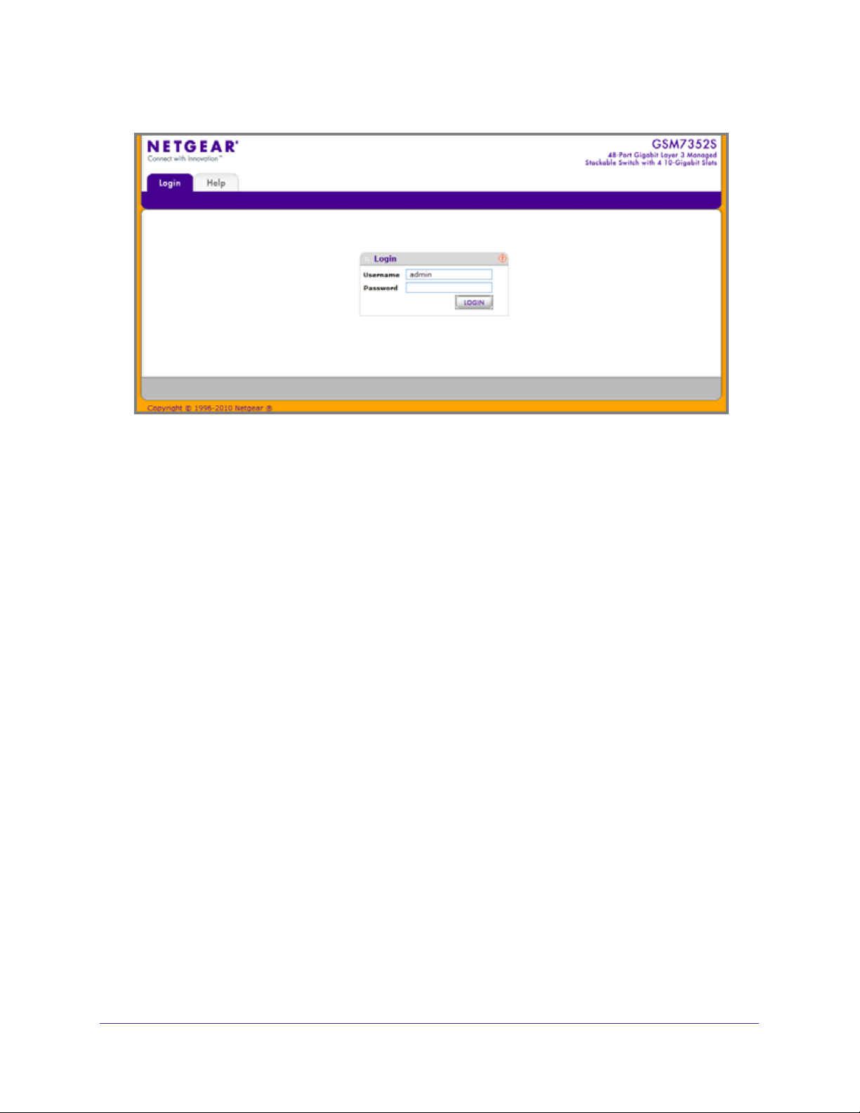
Accessing the switch directly from your Web browser displays the login screen shown below.
Chapter 1. Getting Started | 9
Page 10
ProSafe® Gigabit L3 Managed Stackable Switches Software Administration Manual
Understanding the User Interfaces
ProSafe® Managed Switches software includes a set of comprehensive management
functions for configuring and monitoring the system by using one of the following methods:
• Web user interface
• Simple Network Management Protocol (SNMP)
• Command Line Interface (CLI)
Each of the standards-based management methods allows you to configure and monitor the
components of the ProSafe® Managed Switches software. The method you use to manage
the system depends on your network size and requirements, and on your preference.
The ProSafe® Managed Switch Web Management User Manual describes how to use the
Web-based interface to manage and monitor the system.
Using the Web Interface
To access the switch by using a Web browser, the browser must meet the following software
requirements:
• HTML version 4.0, or later
• HTTP version 1.1, or later
• Java Runtime Environment 1.6 or later
Use the following procedures to log on to the Web interface:
1. Open a Web browser and enter the IP address of the switch in the Web browser
address field.
10 | Chapter 1. Getting Started
Page 11
ProSafe® Gigabit L3 Managed Stackable Switches Software Administration Manual
2. The default username is admin, default password is none (no password). Type the
username into the field on the login screen and then click Login. Usernames and
passwords are case sensitive.
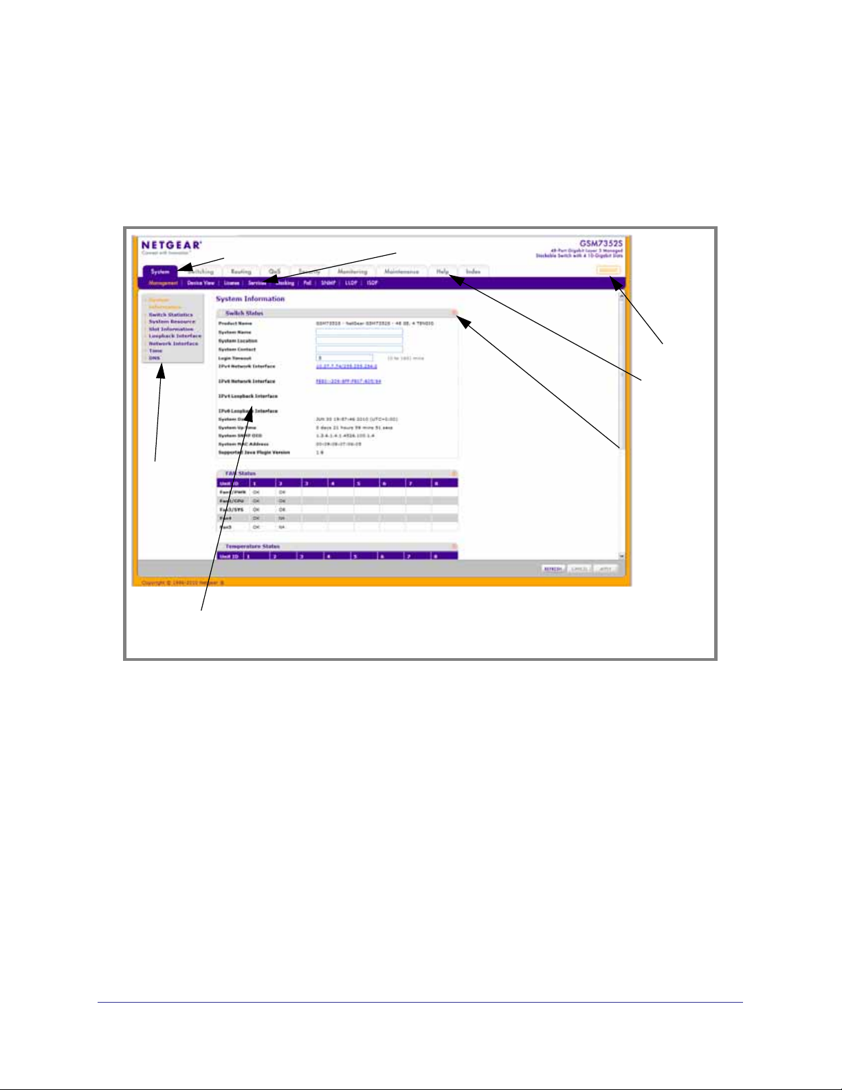
3. After the system authenticates you, the System Information page displays.
The figure below shows the layout of the Managed Switch Web interface.
Navigation Tab
Page Menu
Configuration Status and Options
Feature Link
Logout
Button
Help LInk
Help Page
Chapter 1. Getting Started | 11
Page 12
ProSafe® Gigabit L3 Managed Stackable Switches Software Administration Manual
Navigation Tabs, Feature Links, and Page Menu
The navigation tabs along the top of the Web interface give you quick access to the various
switch functions. The tabs are always available and remain constant, regardless of which
feature you configure.
When you select a tab, the features for that tab appear as links directly under the tabs. The
feature links in the blue bar change according to the navigation tab that is selected.
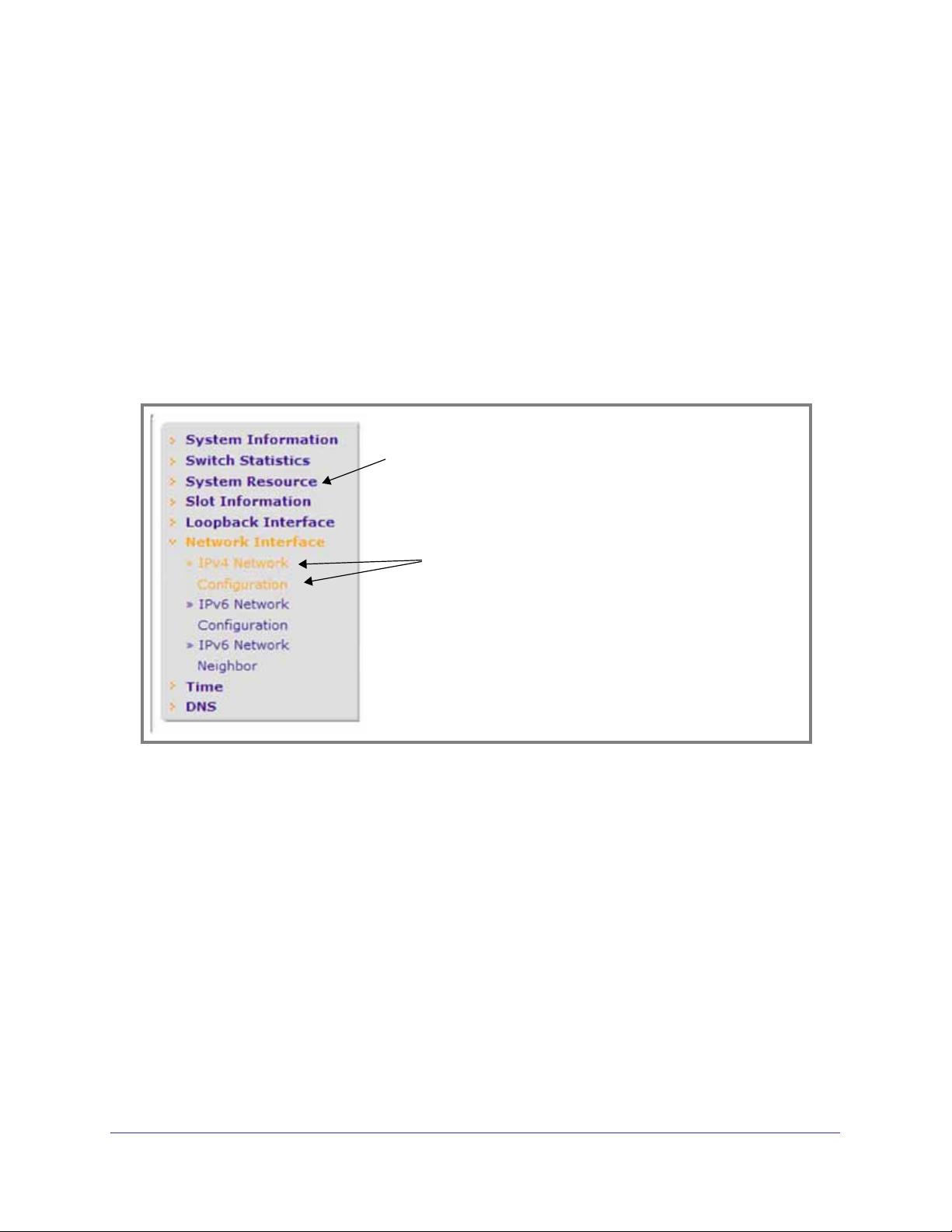
The configuration pages for each feature are available as links in the page menu on the left
side of the page. Some items in the menu expand to reveal multiple configuration pages, as
the following figure shows. When you click a menu item that includes multiple configuration
pages, the item becomes preceded by a down arrow symbol and expands to display the
additional pages.
Page Link
Configuration
Pages
12 | Chapter 1. Getting Started
Page 13

ProSafe® Gigabit L3 Managed Stackable Switches Software Administration Manual
Configuration and Monitoring Options
The area directly under the feature links and to the right of the page menu displays the
configuration information or status for the page you select. On pages that contain
configuration options, you can input information into fields or select options from drop-down
menus.
Each page contains access to the HTML-based help that explains the fields and
configuration options for the page. Each page also contains command buttons.
Table 1 shows the command buttons that are used throughout the pages in the Web
interface:
Table 1.
Button Function
Add Clicking Add adds the new item configured in the heading row of a table.
Apply Clicking the Apply button sends the updated configuration to the switch. Configuration
changes take effect immediately.
Cancel Clicking Cancel cancels the configuration on the screen and resets the data on the screen
to the latest value of the switch.
Delete Clicking Delete removes the selected item.
Refresh Clicking the Refresh button refreshes the page with the latest information from the device.
Logout Clicking the
Logout button ends the session.
Chapter 1. Getting Started | 13
Page 14
ProSafe® Gigabit L3 Managed Stackable Switches Software Administration Manual
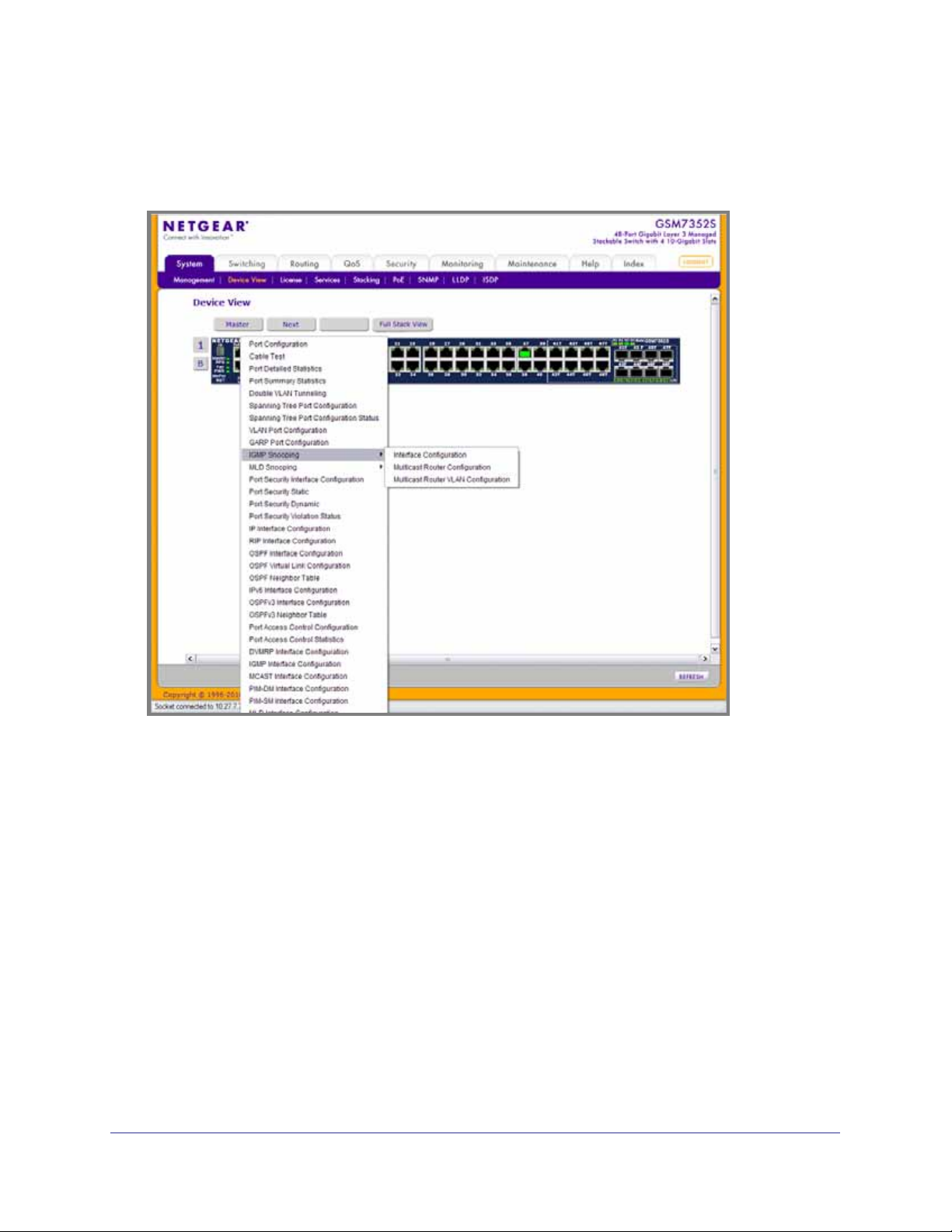
Device View
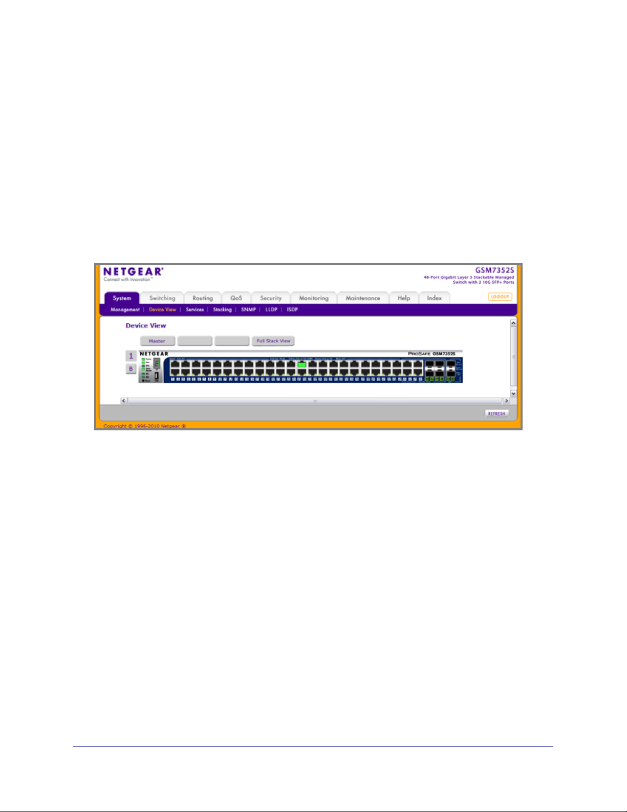
The Device View is a Java® applet that displays the ports on the switch. This graphic provides
an alternate way to navigate to configuration and monitoring options. The graphic also
provides information about device ports, current configuration and status, table information,
and feature components.
The Device View is available from the System
Device View page.
The port coloring indicates whether a port is currently active. Green indicates that the port is
enabled, red indicates that an error has occurred on the port, or red indicates that the link is
disabled.
The Device View of the switch is shown below.
14 | Chapter 1. Getting Started
Page 15
ProSafe® Gigabit L3 Managed Stackable Switches Software Administration Manual
Click the port you want to view or configure to see a menu that displays statistics and
configuration options. Click the menu option to access the page that contains the
configuration or monitoring options.
Chapter 1. Getting Started | 15
Page 16
ProSafe® Gigabit L3 Managed Stackable Switches Software Administration Manual
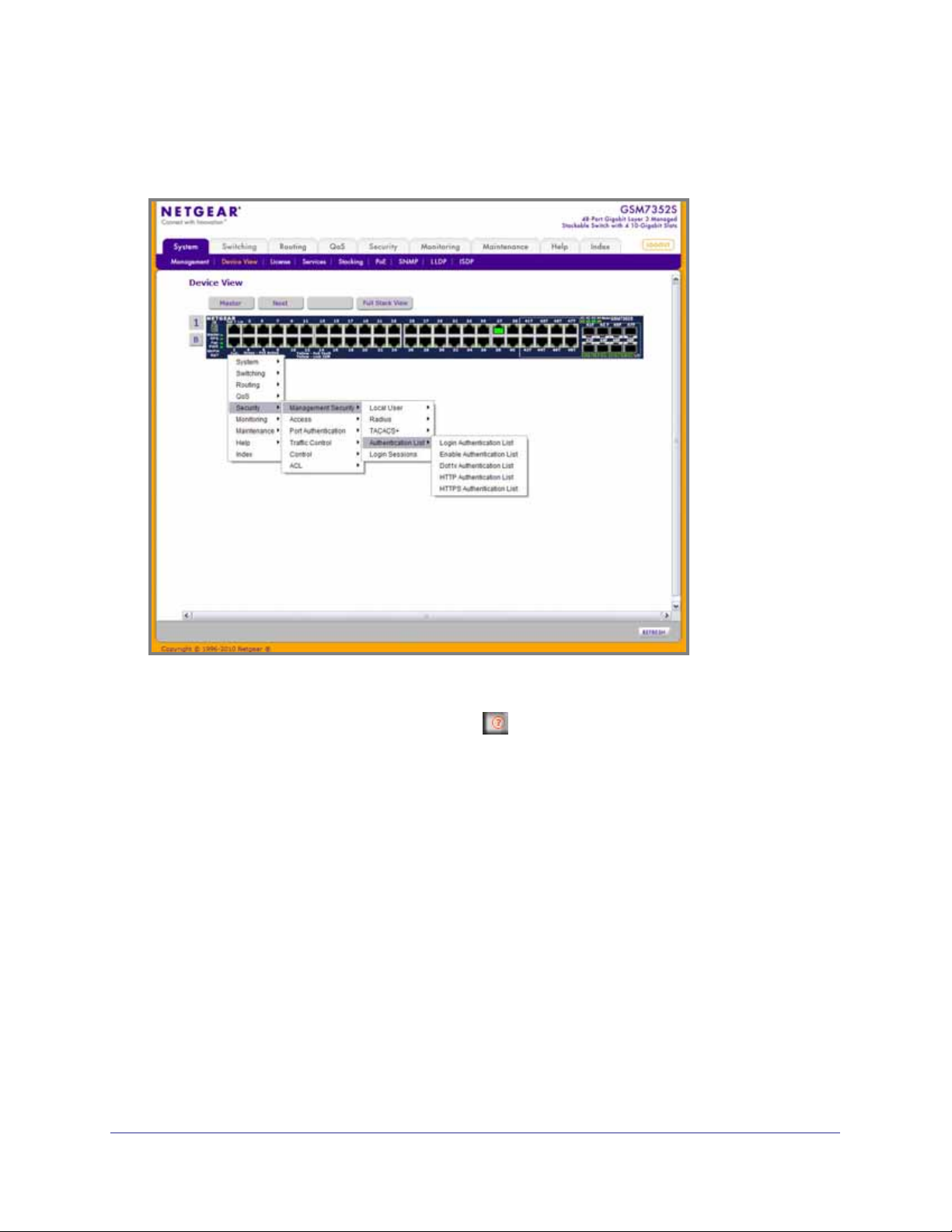
If you click the graphic, but do not click a specific port, the main menu appears. This menu
contains the same option as the navigation tabs at the top of the page.
Help Page Access
Every page contains a link to the online help , which contains information to assist in
configuring and managing the switch. The online help pages are context sensitive. For
example, if the IP Addressing page is open, the help topic for that page displays if you click
Help.
16 | Chapter 1. Getting Started
Page 17

ProSafe® Gigabit L3 Managed Stackable Switches Software Administration Manual
User-Defined Fields
User-defined fields can contain 1 to 159 characters, unless otherwise noted on the
configuration Web page. All characters may be used except for the following (unless
specifically noted in for that feature):
Table 2.
\ <
/ >|
* |
?
Using SNMP
The ProSafe® Managed Switches software supports the configuration of SNMP groups and
users that can manage traps that the SNMP agent generates.
ProSafe® Managed Switches use both standard public MIBs for standard functionality and
private MIBs that support additional switch functionality. All private MIBs begin with a “-”
prefix. The main object for interface configuration is in -SWITCHING-MIB, which is a private
MIB. Some interface configurations also involve objects in the public MIB, IF-MIB.
SNMP is enabled by default. The System
Management System Information Web page,
which is the page that displays after a successful login, displays the information you need to
configure an SNMP manager to access the switch.
Any user can connect to the switch using the SNMPv3 protocol, but for authentication and
encryption, the switch supports only one user which is admin; therefore there is only one
profile that can be created or modified.
To configure authentication and encryption settings for the SNMPv3 admin profile by using
the Web interface:
1. Navigate to the System
SNMP SNMPv3 User Configuration page.
2. To enable authentication, select an Authentication Protocol option, which is either MD5 or
SHA.
3. To enable encryption, select the DES option in the Encryption Protocol field. Then, enter
an encryption code of eight or more alphanumeric characters in the Encryption Key field.
4. Click Apply.
To access configuration information for SNMPv1 or SNMPv2, click System
SNMP
SNMPv1/v2 and click the page that contains the information to configure.
Chapter 1. Getting Started | 17
Page 18

ProSafe® Gigabit L3 Managed Stackable Switches Software Administration Manual
Interface Naming Convention
The ProSafe® Managed Switches support physical and logical interfaces. Interfaces are
identified by their type and the interface number. The physical ports are gigabit interfaces and
are numbered on the front panel. You configure the logical interfaces by using the software.
Table 3 describes the naming convention for all interfaces available on the switch.
Table 3.
Interface Description Example
Physical The physical ports are gigabit
Ethernet interfaces and are
numbered sequentially starting
from one.
Link Aggregation Group (LAG) LAG interfaces are logical
interfaces that are only used for
bridging functions.
CPU Management Interface This is the internal switch interface
responsible for the switch base
MAC address. This interface is not
configurable and is always listed in
the MAC Address Table.
Routing VLAN Interfaces This is an interface used for routing
functionality.
1/0/1, 1/0/2, 1/0/3, and so on
lag 1, lag 2, lag 3, and so on
0/5/1
Vlan 1, Vlan 2, Vlan 3, and so on
18 | Chapter 1. Getting Started
Page 19

2. Configuring System Information
Use the features in the System tab to define the switch’s relationship to its environment. The
System tab contains links to the following features:
• Management on page 19
• Device View (See Device View on page 14)
• License on page 49
• Services on page 50
• Stacking on page 79
• PoE on page 86
• SNMP on page 93
• LLDP on page 102
• ISDP on page 121
2
Management
This section describes how to display the switch status and specify some basic switch
information, such as the management interface IP address, system clock settings, and DNS
information. From the Management link, you can access the following pages:
• System Information on page 20
• Switch Statistics on page 26
• System Resource on page 29
• Slot Information on page 30
• Loopback Interface on page 32
• Network Interface on page 33
• Time on page 38
• DNS on page 46
Chapter 2. Configuring System Information | 19
Page 20
ProSafe® Gigabit L3 Managed Stackable Switches Software Administration Manual
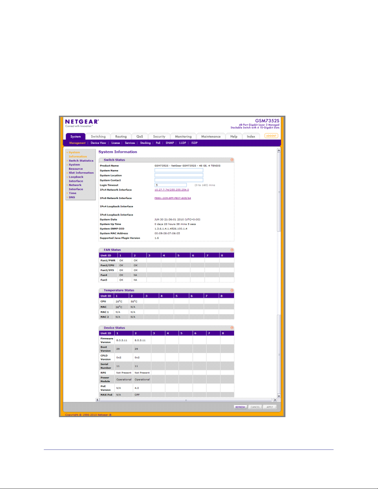
System Information
After a successful login, the System Information page displays. Use this page to configure
and view general device information.
To display the System Information page, click System Management System Information.
A screen similar to the following displays.
20 | Chapter 2. Configuring System Information
Page 21
ProSafe® Gigabit L3 Managed Stackable Switches Software Administration Manual
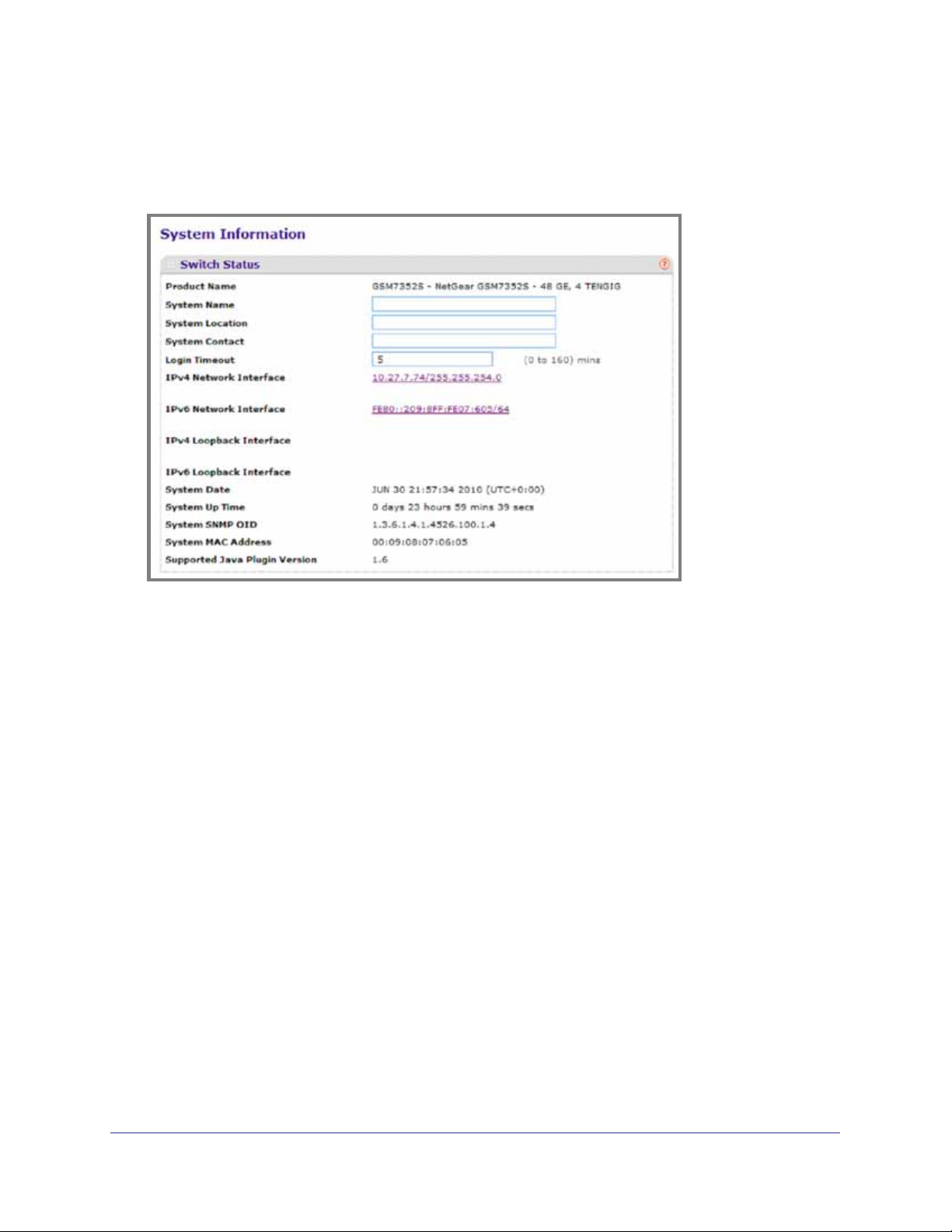
The System Information provides various statuses:
Switch Status
To define system information:
1. Open the System Information page.
2. Define the following fields:
a. System Name - Enter the name you want to use to identify this switch. You may use
up to 255 alphanumeric characters. The factory default is blank.
b. System Location - Enter the location of this switch. You may use up to 255
alphanumeric characters. The factory default is blank.
c. System Contact - Enter the contact person for this switch. You may use up to 25
alphanumeric characters. The factory default is blank.
d. Login Timeout - Specify how many minutes of inactivity should occur on a serial
port connection before the switch closes the connection. Enter a number between 0
and 160: the factory default is 5. Entering 0 disables the timeout.
3. Click Apply to send the updated screen to the switch and cause the changes to take effect
on the switch. These changes will not be retained across a power cycle unless a save is
performed.
Chapter 2. Configuring System Information | 21
Page 22

ProSafe® Gigabit L3 Managed Stackable Switches Software Administration Manual
The following table describes the status information the System Page displays.
Table 2-1.
Field Description
Product Name The product name of this switch.
IPv4 Network Interface The IPv4 address and mask assigned to the network
interface.
IPv6 Network Interface The IPv6 prefix and prefix length assigned to the
network interface.
IPv4 Loopback Interface The IPv4 address and mask assigned to the
loopback interface.
IPv6 Loopback Interface The IPv6 prefix and prefix length assigned to the
loopback interface.
System Date The current date.
System Up time The time in days, hours and minutes since the last
switch reboot.
System SNMP OID The base object ID for the switch's enterprise MIB.
System Mac Address Universally assigned network address.
Supported Java Plugin Version The supported version of Java plugin.
22 | Chapter 2. Configuring System Information
Page 23
ProSafe® Gigabit L3 Managed Stackable Switches Software Administration Manual
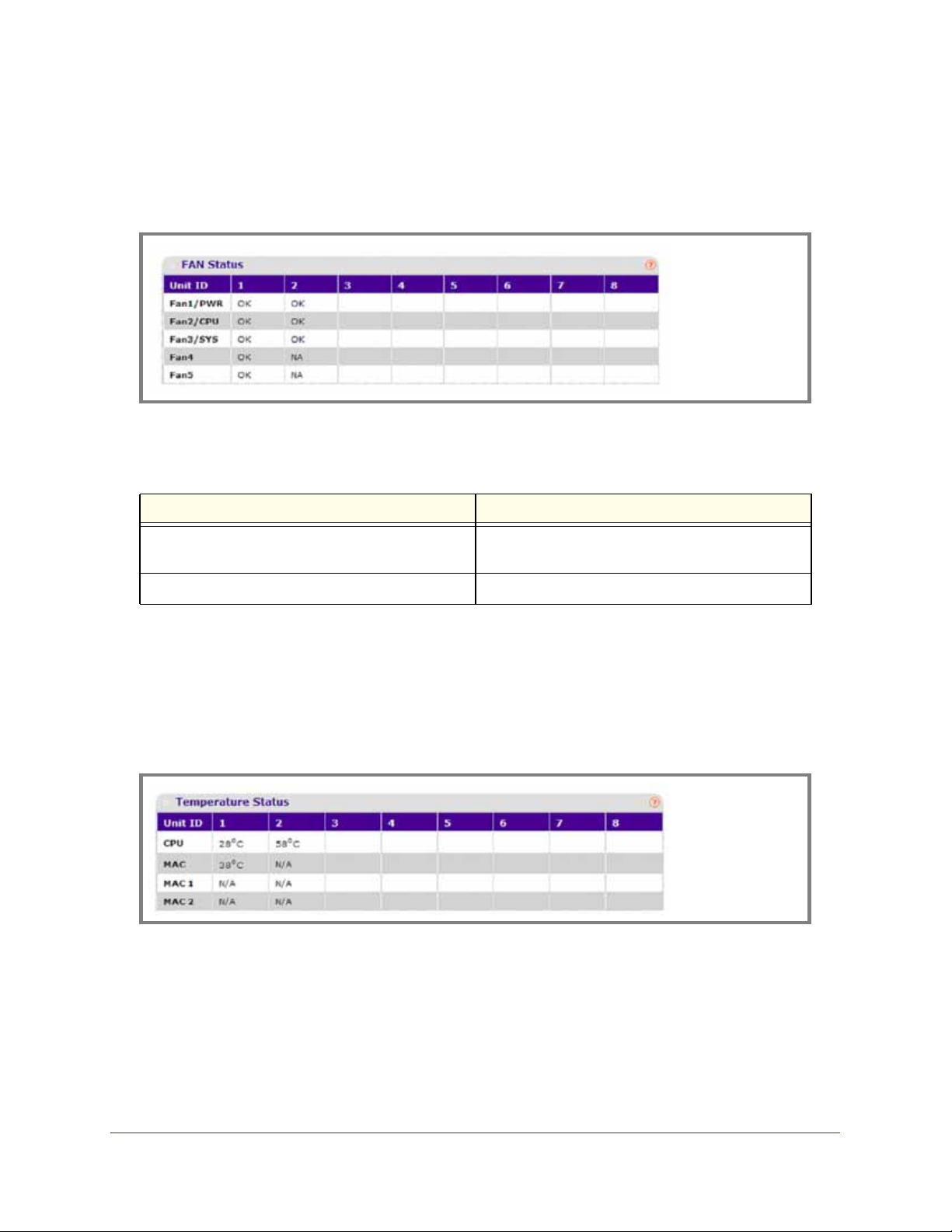
FAN Status
The screen shows the status of the fans in all units. These fans remove the heat generated
by the power, CPU and other chipsets, make chipsets work normally. Fan status has three
possible values: OK, Failure, Not Applicable (NA).
The following table describes the Fan Status information.
Table 2-2.
Field Description
UNIT ID The unit identifier is assigned to the switch which the
fan belongs to.
FAN The working status of the fan in each unit.
Click REFRESH to refresh the system information of the switch.
Temperature Status
The screen shows the current temperature of the CPU and MACs. The temperature is instant
and can be refreshed when the REFRESH button is pressed. The maximum temperature of
CPU and MACs depends on the actual hardware.
The following table describes the Temperature Status information.
Chapter 2. Configuring System Information | 23
Page 24
ProSafe® Gigabit L3 Managed Stackable Switches Software Administration Manual
Table 2-3.
Field Description
CPU The current temperature of the CPU in the switch.
MAC The current temperature of the MACs in the switch.
Click REFRESH to refresh the system information of the switch.
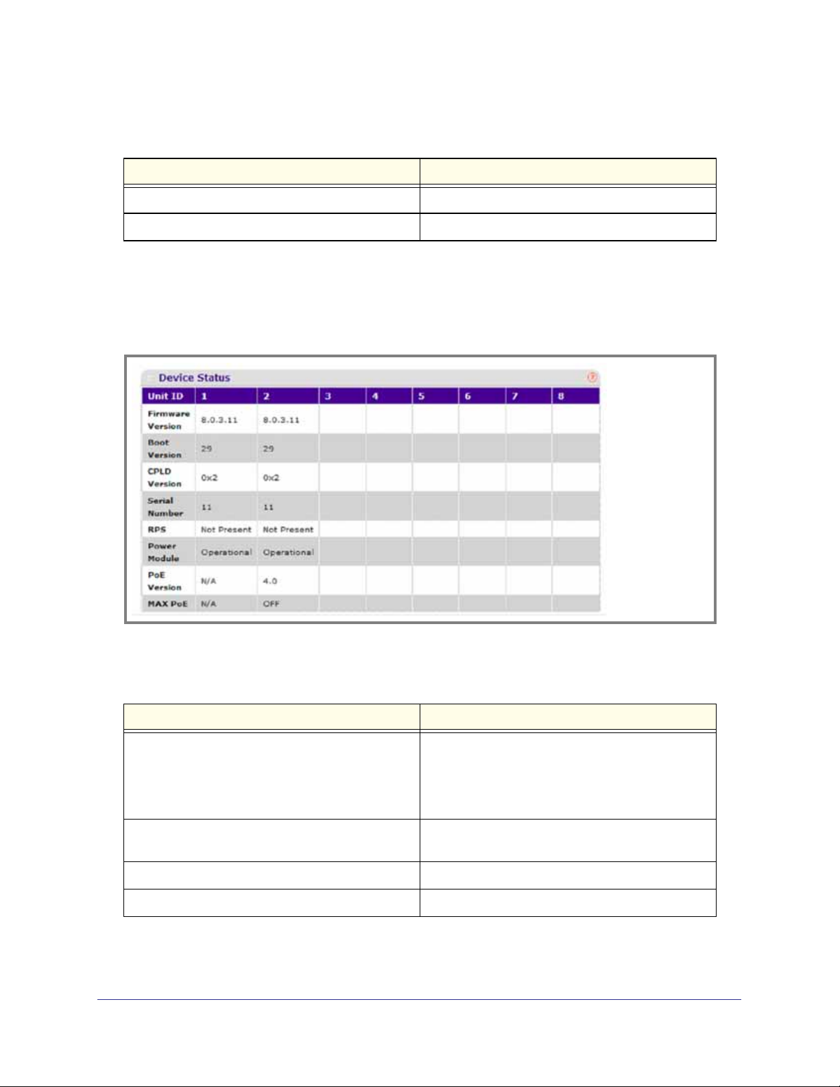
Device Status
The screen shows the software version of each device.
The following table describes the Device Status information.
Table 2-4.
Field Description
Firmware Version The release.version.maintenance.build number of
the code currently running on the switch. For
example, if the release was 8, the version was 0, the
maintenance number was 3, and the build number
was 11, the format would be ‘8.0.3.11’.
Boot Version The version of the boot code which is in the flash
memory to load the firmware into the memory.
CPLD Version The version of the software for CPLD.
Serial Number The serial number of this switch.
24 | Chapter 2. Configuring System Information
Page 25

ProSafe® Gigabit L3 Managed Stackable Switches Software Administration Manual
Table 2-4.
Field Description
RPS Indicates the status of the RPS. The status has three
possible values:
• Not Present: RPS bank not connected
• OK: RPS bank connected.
• FAIL: RPS is present, but power is failed.
Power Module Indicates the status of the internal power module.
PoE Version Version of the PoE controller FW image.
MAX PoE Indicates the status of maximum PoE power
available on the switch as follows:
• ON: Indicates less than 7W of PoE power
available for another device.
• OFF: Indicates at least 7W of PoE power
available for another device.
• N/A: Indicates that PoE is not supported by the
unit.
Click REFRESH to refresh the system information of the switch.
Chapter 2. Configuring System Information | 25
Page 26
ProSafe® Gigabit L3 Managed Stackable Switches Software Administration Manual
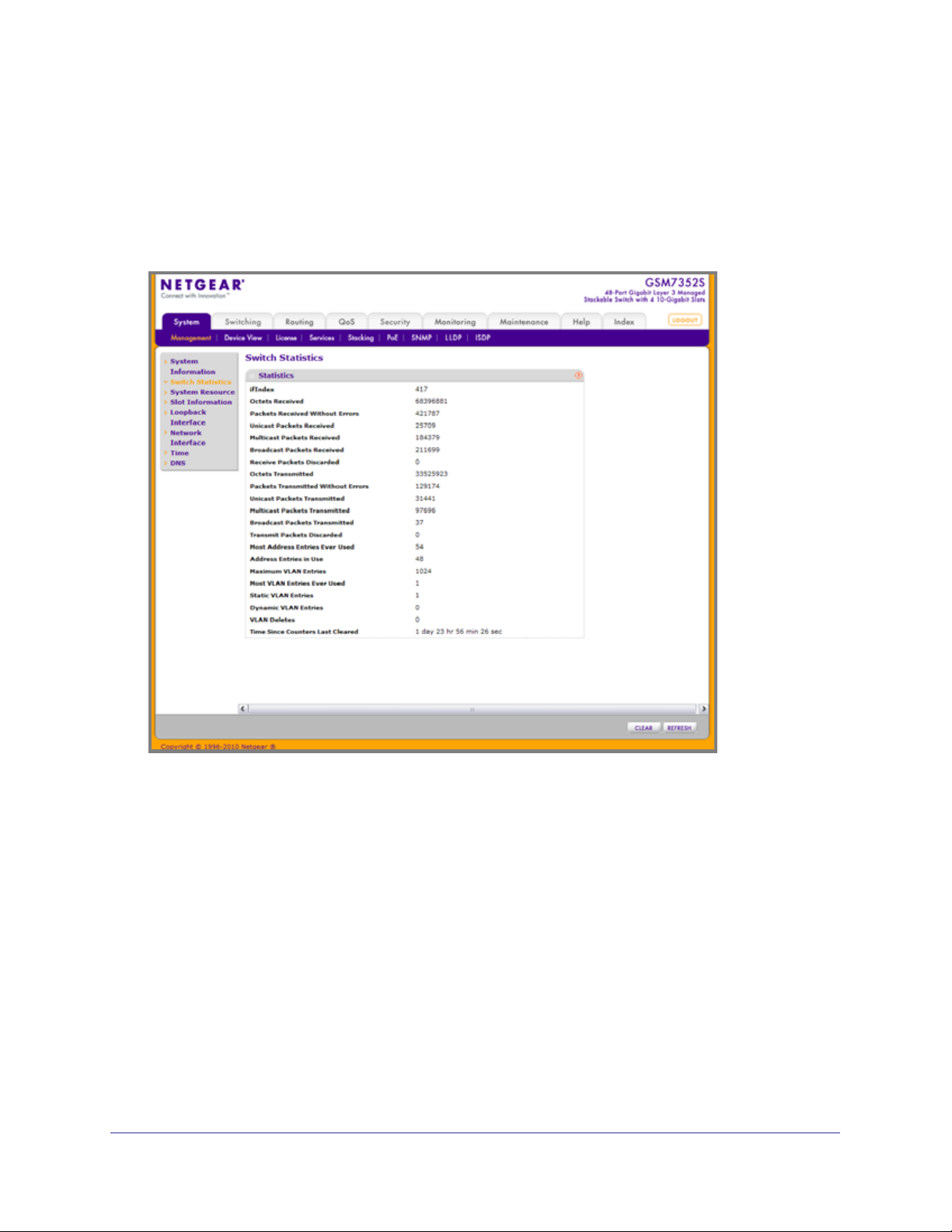
Switch Statistics
Use this page to display the switch statistics.
To display the Switch Statistics page, click System > Management > Switch Statistics. A
screen similar to the following displays.
26 | Chapter 2. Configuring System Information
Page 27

ProSafe® Gigabit L3 Managed Stackable Switches Software Administration Manual
The following table describes Switch Statistics information.
Table 2-5.
Field Description
ifIndex This object indicates the ifIndex of the interface table
entry associated with the Processor of this switch.
Octets Received The total number of octets of data received by the
processor (excluding framing bits but including FCS
octets).
Packets Received Without Errors The total number of packets (including broadcast
packets and multicast packets) received by the
processor.
Unicast Packets Received The number of subnetwork-unicast packets delivered
to a higher-layer protocol.
Multicast Packets Received The total number of packets received that were
directed to a multicast address. Note that this
number does not include packets directed to the
broadcast address.
Broadcast Packets Received The total number of packets received that were
directed to the broadcast address. Note that this
does not include multicast packets.
Receive Packets Discarded The number of inbound packets which were chosen
to be discarded even though no errors had been
detected to prevent their being deliverable to a
higher-layer protocol. A possible reason for
discarding a packet could be to free up buffer space.
Octets Transmitted The total number of octets transmitted out of the
interface, including framing characters.
Packets Transmitted Without Errors The total number of packets transmitted out of the
interface.
Unicast Packets Transmitted The total number of packets that higher-level
protocols requested be transmitted to a
subnetwork-unicast address, including those that
were discarded or not sent.
Multicast Packets Transmitted The total number of packets that higher-level
protocols requested be transmitted to a Multicast
address, including those that were discarded or not
sent.
Broadcast Packets Transmitted The total number of packets that higher-level
protocols requested be transmitted to the Broadcast
address, including those that were discarded or not
sent.
Chapter 2. Configuring System Information | 27
Page 28

ProSafe® Gigabit L3 Managed Stackable Switches Software Administration Manual
Table 2-5.
Field Description
Transmit Packets Discarded The number of outbound packets which were chosen
to be discarded even though no errors had been
detected to prevent their being deliverable to a
higher-layer protocol. A possible reason for
discarding a packet could be to free up buffer space.
Most Address Entries Ever Used The highest number of Forwarding Database
Address Table entries that have been learned by this
switch since the most recent reboot.
Address Entries in Use The number of Learned and static entries in the
Forwarding Database Address Table for this switch.
Maximum VLAN Entries The maximum number of Virtual LANs (VLANs)
allowed on this switch.
Most VLAN Entries Ever Used The largest number of VLANs that have been active
on this switch since the last reboot.
Static VLAN Entries The number of presently active VLAN entries on this
switch that have been created statically.
Dynamic VLAN Entries The number of presently active VLAN entries on this
switch that have been created by GVRP registration.
VLAN Deletes The number of VLANs on this switch that have been
created and then deleted since the last reboot.
Time Since Counters Last Cleared The elapsed time, in days, hours, minutes, and
seconds, since the statistics for this switch were last
cleared.
Click CLEAR to clear all the counters, resetting all switch summary and detailed statistics to
default values. The discarded packets count cannot be cleared.
28 | Chapter 2. Configuring System Information
Page 29
ProSafe® Gigabit L3 Managed Stackable Switches Software Administration Manual
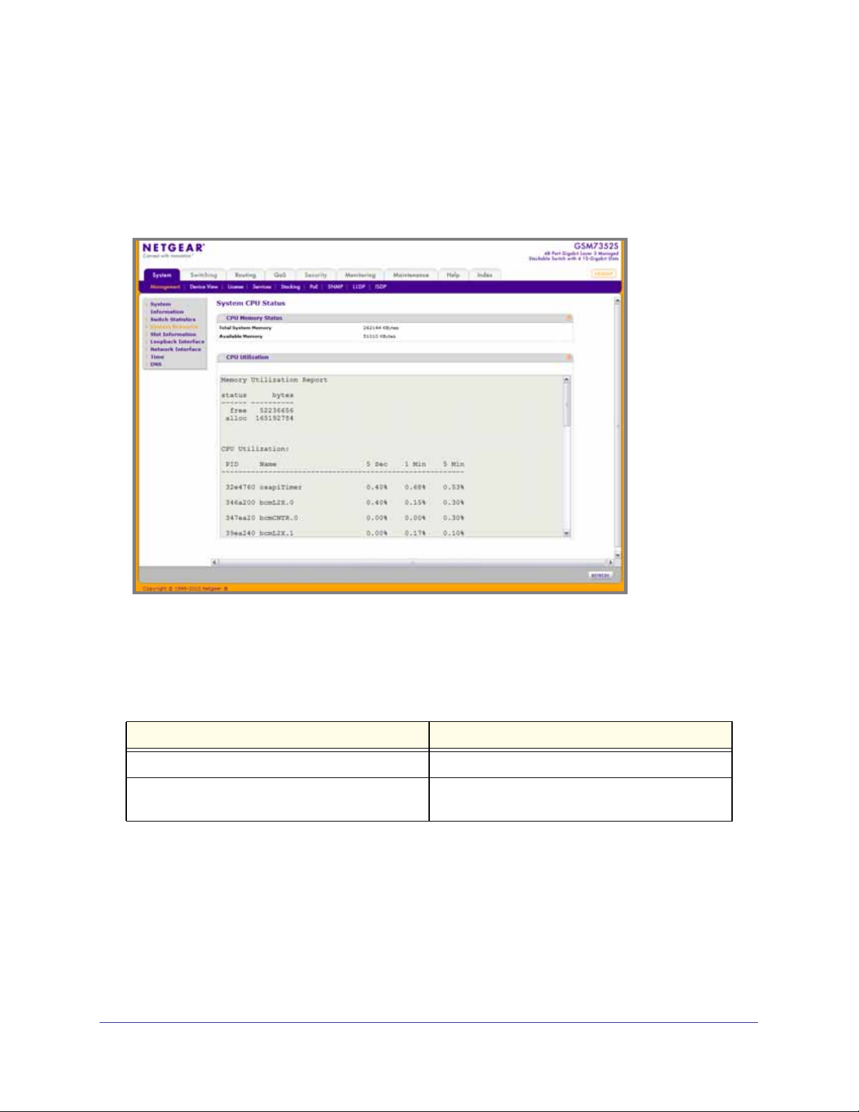
System Resource
Use this page to display the system resources.
To display the System Resource page, click System > Management > System Resource. A
screen similar to the following displays.
CPU Memory Status
The following table describes CPU Memory Status information.
Table 2-6.
Field Description
Total System Memory The total memory of the switch in KBytes.
Available Memory The available memory space for the switch in
KBytes.
CPU Utilization Information
This page displays the CPU Utilization information, which contains the memory information,
task-related information and percentage of CPU utilization per task.
Chapter 2. Configuring System Information | 29
Page 30
ProSafe® Gigabit L3 Managed Stackable Switches Software Administration Manual
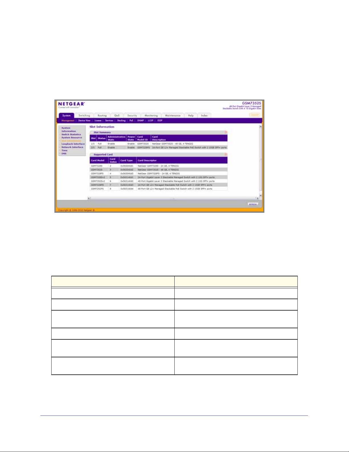
Slot Information
Use this page to display slot information and supported cards.
To display the Slot Information page, click System > Management > Slot Information. A
screen similar to the following displays.
Slot Summary
This screen displays details of the different slots in the different units in the stack.
The following table displays Slot Summary information.
Table 2-7.
Field Description
Slot Identifies the slot using the format unit/slot.
Status Displays whether the slot is empty or full.
Administrative State Displays whether the slot is administratively enabled
or disabled
Power State Displays whether the slot is powered on of off.
Card Model ID Displays the model ID of the card configured for the
slot.
Card Description Displays the description of the card configured for
the slot.
30 | Chapter 2. Configuring System Information
Page 31

ProSafe® Gigabit L3 Managed Stackable Switches Software Administration Manual
Supported Cards
The following table displays Supported Cards information.
Table 2-8.
Field Description
Card Model Displays the list of models of all cards that can be
supported.
Card Index Displays the index assigned to the selected card
type.
Card Type Displays the hardware type of this supported card.
This is a 32-bit data field.
Card Descriptor Displays a data field used to identify the supported
card.
Chapter 2. Configuring System Information | 31
Page 32

ProSafe® Gigabit L3 Managed Stackable Switches Software Administration Manual
Loopback Interface
Use this page to create, configure, and remove Loopback interfaces.
To display the Loopback Interface page, click System > Management > Loopback Interface.
A screen similar to the following displays.
1. Use the Loopback Interface Type field to select IPv4 or IPv6 loopback interface to
configure the corresponding attributes.
2. Use the Loopback ID field to select list of currently configured loopback interfaces.
3. Use the Primary Address field to input the primary IPv4 address for this interface in dotted
decimal notation. This option only visible when IPv4 loopback is selected.
4. Use the Primary Mask field to input the primary IPv4 subnet mask for this interface in dotted
decimal notation. This option only visible when IPv4 loopback is selected.
5. Use the Secondary IP Address field to input the secondary IP address for this interface in
dotted decimal notation. This input field is visible only when 'Add Secondary' is selected.
This option only visible when IPv4 loopback is selected.
6. Use the Secondary Subnet Mask field to input the secondary subnet mask for this interface
in dotted decimal notation. This input field is visible only when 'Add Secondary' is selected.
This option only visible when IPv4 loopback is selected.
7. Use the IPv6 Mode field to enable IPv6 on this interface using the IPv6 address. This option
is only configurable prior to specifying an explicit IPv6 address. This option only visible when
IPv6 loopback is selected.
8. Use the IPv6 Address field to enter the IPv6 address in the format prefix/length. This option
only visible when IPv6 loopback is selected.
9. Use the EUI64 field to optionally specify the 64-bit extended unique identifier (EUI-64). This
option only visible when IPv6 loopback is selected.
32 | Chapter 2. Configuring System Information
Page 33

ProSafe® Gigabit L3 Managed Stackable Switches Software Administration Manual
Network Interface
From the Network Interface link, you can access the following pages:
• IPv4 Network Configuration on page 33
• IPv6 Network Configuration on page 35n
• IPv6 Network Neighbor on page 37
IPv4 Network Configuration
To display the IPv4 Network Configuration page, click System > Management > Network
Interface > IPv4 Network Configuration. A screen similar to the following displays.
The network interface is the logical interface used for in-band connectivity with the switch via
any of the switch's front panel ports. The configuration parameters associated with the
switch's network interface do not affect the configuration of the front panel ports through
which traffic is switched or routed
To access the switch over a network you must first configure it with IP information (IP
address, subnet mask, and default gateway). You can configure the IP information using any
of the following:
• BOOTP
• DHCP
• Terminal interface via the EIA-232 port
Chapter 2. Configuring System Information | 33
Page 34

ProSafe® Gigabit L3 Managed Stackable Switches Software Administration Manual
Once you have established in-band connectivity, you can change the IP information using
any of the following:
• Terminal interface via the EIA-232 port
• Terminal interface via telnet
• SNMP-based management
• Web-based management
1. Use IP Address to specify the IP address of the interface. The factory default value is
169.254.100.100.
2. Use Subnet Mask to enter the IP subnet mask for the interface. The factory default value is
255.255.0.0.
3. Use Default Gateway to specify the default gateway for the IP interface. The factory default
value is 0.0.0.0
4. Use Locally Administered MAC Address to configure a locally administered MAC address
for in-band connectivity instead of using the burned-in universally administered MAC
address. In addition to entering an address in this field, you must also set the MAC address
type to locally administered. Enter the address as twelve hexadecimal digits (6 bytes) with a
colon between each byte. Bit 1 of byte 0 must be set to a 1 and bit 0 to a 0, in other words,
byte 0 must have a value between x'40' and x'7F'.
5. Use MAC Address type to specify whether the burned-in or the locally administered MAC
address should be used for in-band connectivity. The factory default is to use the burned-in
MAC address
6. Use Current Network Configuration Protocol to specify what the switch should do
following power-up: transmit a Bootp request, transmit a DHCP request, or do nothing
(none). The factory default is DHCP.
7. Use DHCP Vendor Class Identifier to enable DHCP VendorId option on the client.
8. Use DHCP Vendor Class Identifier String to specify DHCP VendorId option string on the
client.
9. Use Management VLAN ID to specify the management VLAN ID of the switch. It may be
configured to any value in the range of 1 - 4093. The management VLAN is used for
management of the switch. This field is configurable for administrative users and read-only
for other users.
The following table describes IPv4 Network Configuration information.
Table 2-9.
Field Description
Burned In MAC Address The burned-in MAC address used for in-band
connectivity if you choose not to configure a locally
administered address.
34 | Chapter 2. Configuring System Information
Page 35

ProSafe® Gigabit L3 Managed Stackable Switches Software Administration Manual
IPv6 Network Configuration
To display the IPv6 Network Configuration page, click System > Management > Network
Interface > IPv6 Network Configuration. A screen similar to the following displays.
The IPv6 network interface is the logical interface used for in-band connectivity with the
switch via any of the switch's front panel ports. The configuration parameters associated with
the switch's network interface do not affect the configuration of the front panel ports through
which traffic is switched or routed
To access the switch over an IPv6 network you must first configure it with IPv6 information
(IPv6 prefix, prefix length, and default gateway). You can configure the IP information using
any of the following:
• IPv6 Auto Configuration
• DHCPv6
• Terminal interface via the EIA-232 port
Once you have established in-band connectivity, you can change the IPv6 information using
any of the following:
• Terminal interface via the EIA-232 port
• Terminal interface via telnet
• SNMP-based management
• Web-based management
Chapter 2. Configuring System Information | 35
Page 36

ProSafe® Gigabit L3 Managed Stackable Switches Software Administration Manual
1. Use Admin Mode to enable or disable the IPv6 network interface on the switch. The
default value is enable.
2. Use IPv6 Address Auto Configuration Mode to set the IPv6 address for the IPv6 network
interface in auto configuration mode if this option is enabled. The default value is disable.
Auto configuration can be enabled only when IPv6 Auto config or DHCPv6 are not enabled
on any of the management interfaces.
3. Use Current Network Configuration Protocol to configure the IPv6 address for the IPv6
network interface by DHCPv6 protocol if this option is enabled. The default value is None.
DHCPv6 can be enabled only when IPv6 Auto config or DHCPv6 are not enabled on any of
the management interfaces.
4. Use DHCPv6 Client DUID to specify an Identifier used to identify the client's unique DUID
value. This option only displays when DHCPv6 is enabled.
5. Use IPv6 Gateway to specify the gateway for the IPv6 network interface. The gateway
address is in IPv6 global or link-local address format.
6. Use IPv6 Prefix/Prefix Length to add the IPv6 prefix and prefix length to the IPv6 network
interface. The address is in global address format.
7. Use EUI64 to specify whether to format the IPv6 address in EUI-64 format. Default value is
false.
8. Click ADD to add a new IPv6 address in global format.
9. Click DELETE to delete a selected IPv6 address.
36 | Chapter 2. Configuring System Information
Page 37

ProSafe® Gigabit L3 Managed Stackable Switches Software Administration Manual
IPv6 Network Neighbor
Use this page to display IPv6 Network Port Neighbor entries.
To display the IPv6 Network Neighbor page, click System > Management > Network
Interface > IPv6 Network Neighbor. A screen similar to the following displays.
The following table displays IPv6 Network Interface Neighbor Table information.
Table 2-10.
Field Description
IPv6 address The Ipv6 Address of a neighbor switch visible to the
network interface.
MAC address The MAC address of a neighbor switch.
IsRtr True(1) if the neighbor machine is a router, false(2)
otherwise.
Neighbor State The state of the neighboring switch:
• reachable(1) - The neighbor is reachable by this
switch.
• stale(2) - Information about the neighbor is
scheduled for deletion.
• delay(3) - No information has been received from
neighbor during delay period.
• probe(4) - Switch is attempting to probe for this
neighbor.
• unknown(6) - Unknown status.
Last Updated The last sysUpTime that this neighbor has been
updated.
Chapter 2. Configuring System Information | 37
Page 38

ProSafe® Gigabit L3 Managed Stackable Switches Software Administration Manual
Time
ProSafe® Managed Switches software supports the Simple Network Time Protocol (SNTP).
You can also set the system time manually
SNTP assures accurate network device clock time synchronization up to the millisecond.
Time synchronization is performed by a network SNTP server. ProSafe® Managed Switches
software operates only as an SNTP client and cannot provide time services to other systems.
Time sources are established by Stratums. Stratums define the accuracy of the reference
clock. The higher the stratum (where zero is the highest), the more accurate the clock. The
device receives time from stratum 1 and above since it is itself a stratum 2 device.
The following is an example of stratums:
• Stratum 0: A real-time clock is used as the time source, for example, a GPS system.
• Stratum 1: A server that is directly linked to a Stratum 0 time source is used. Stratum 1
time servers provide primary network time standards.
• Stratum 2: The time source is distanced from the Stratum 1 server over a network path.
For example, a Stratum 2 server receives the time over a network link, via NTP, from a
Stratum 1 server.
Information received from SNTP servers is evaluated based on the time level and server
type.
SNTP time definitions are assessed and determined by the following time levels:
• T1: Time at which the original request was sent by the client.
• T2: Time at which the original request was received by the server.
• T3: Time at which the server sent a reply.
• T4: Time at which the client received the server's reply.
The device can poll Unicast server types for the server time.
Polling for Unicast information is used for polling a server for which the IP address is known.
SNTP servers that have been configured on the device are the only ones that are polled for
synchronization information. T1 through T4 are used to determine server time. This is the
preferred method for synchronizing device time because it is the most secure method. If this
method is selected, SNTP information is accepted only from SNTP servers defined on the
device using the SNTP Server Configuration page.
The device retrieves synchronization information, either by actively requesting information or
at every poll interval.
38 | Chapter 2. Configuring System Information
Page 39

ProSafe® Gigabit L3 Managed Stackable Switches Software Administration Manual
SNTP Global Configuration
Use the SNTP Global Configuration page to view and adjust date and time settings.
To display the SNTP Global Configuration page, click System
Global Configuration.
Management > Time SNTP
SNTP Global Configuration
SNTP stands for Simple Network Time Protocol. As its name suggests, it is a less
complicated version of Network Time Protocol, which is a system for synchronizing the
clocks of networked computer systems, primarily when data transfer is handled via the
Internet.
1. Use Client Mode to specify the mode of operation of SNTP Client. An SNTP client may
operate in one of the following modes.
• Disable - SNTP is not operational. No SNTP requests are sent from the client nor are
any received SNTP messages processed.
• Unicast - SNTP operates in a point to point fashion. A unicast client sends a request
to a designated server at its unicast address and expects a reply from which it can
determine the time and, optionally the round-trip delay and local clock offset relative
to the server.
• Broadcast - SNTP operates in the same manner as multicast mode but uses a local
broadcast address instead of a multicast address. The broadcast address has a
single subnet scope while a multicast address has Internet wide scope.
Chapter 2. Configuring System Information | 39
Page 40

ProSafe® Gigabit L3 Managed Stackable Switches Software Administration Manual
Default value is Disable.
2. Use Port to specify the local UDP port to listen for responses/broadcasts. Allowed range is
1 to 65535. Default value is 123.
3. Use Unicast Poll Interval to specify the number of seconds between unicast poll requests
expressed as a power of two when configured in unicast mode. Allowed range is (6 to 10).
Default value is 6.
4. Use Broadcast Poll Interval to specify the number of seconds between broadcast poll
requests expressed as a power of two when configured in broadcast mode. Broadcasts
received prior to the expiry of this interval are discarded. Allowed range is (6 to 10). Default
value is 6.
5. Use Unicast Poll Timeout to specify the number of seconds to wait for an SNTP response
when configured in unicast mode. Allowed range is (1 to 30). Default value is 5.
6. Use Unicast Poll Retry to specify the number of times to retry a request to an SNTP server
after the first time-out before attempting to use the next configured server when configured in
unicast mode. Allowed range is (0 to 10). Default value is 1.
7. When using SNTP/NTP time servers to update the switch's clock, the time data received
from the server is based on Coordinated Universal Time (UTC) which is the same as
Greenwich Mean Time (GMT). This may not be the time zone in which the switch is located.
Use Time Zone Name to configure a timezone specifying the number of hours and
optionally the number of minutes difference from UTC with Offset Hours and Offset Minutes.
The time zone can affect the display of the current system time. The default value is UTC.
8. Use Offset Hours to specify the number of hours difference from UTC. See Time Zone
Name (
step 7 previous) for more information. Allowed range is (-24 to 24).The default value
is 0.
9. Use Offset Minutes to specify the number of Minutes difference from UTC. See Time Zone
Name (
step 7 previous) for more information. Allowed range is 0 to 59. The default value is
0.
40 | Chapter 2. Configuring System Information
Page 41

ProSafe® Gigabit L3 Managed Stackable Switches Software Administration Manual
SNTP Global Status
The following table displays SNTP Global Status information.
Table 2-11.
Field Description
Version Specifies the SNTP Version the client supports.
Supported Mode Specifies the SNTP modes the client supports.
Multiple modes may be supported by a client.
Last Update Time Specifies the local date and time (UTC) the SNTP
client last updated the system clock.
Last Attempt Time Specifies the local date and time (UTC) of the last
SNTP request or receipt of an unsolicited message.
Last Attempt Status Specifies the status of the last SNTP request or
unsolicited message for both unicast and broadcast
modes. If no message has been received from a
server, a status of Other is displayed. These values
are appropriate for all operational modes.
• Other - None of the following enumeration
values.
• Success - The SNTP operation was successful
and the system time was updated.
• Request Timed Out - A directed SNTP request
timed out without receiving a response from the
SNTP server.
• Bad Date Encoded - The time provided by the
SNTP server is not valid.
• Version Not Supported - The SNTP version
supported by the server is not compatible with the
version supported by the client.
• Server Unsynchronized - The SNTP server is not
synchronized with its peers. This is indicated via
the 'leap indicator' field on the SNTP message.
• Server Kiss Of Death - The SNTP server
indicated that no further queries were to be sent to
this server. This is indicated by a stratum field
equal to 0 in a message received from a server.
Server IP Address Specifies the IP address of the server for the last
received valid packet. If no message has been
received from any server, an empty string is shown.
Address Type Specifies the address type of the SNTP Server
address for the last received valid packet.
Server Stratum Specifies the claimed stratum of the server for the
last received valid packet.
Reference Clock Id Specifies the reference clock identifier of the server
for the last received valid packet.
Chapter 2. Configuring System Information | 41
Page 42

ProSafe® Gigabit L3 Managed Stackable Switches Software Administration Manual
Table 2-11.
Field Description
Server Mode Specifies the mode of the server for the last received
valid packet.
Unicast Server Max Entries Specifies the maximum number of unicast server
entries that can be configured on this client.
Unicast Server Current Entries Specifies the number of current valid unicast server
entries configured for this client.
Broadcast Count Specifies the number of unsolicited broadcast SNTP
messages that have been received and processed
by the SNTP client since last reboot.
42 | Chapter 2. Configuring System Information
Page 43

ProSafe® Gigabit L3 Managed Stackable Switches Software Administration Manual
SNTP Server Configuration
Use the SNTP Server Configuration page to view and modify information for adding and
modifying Simple Network Time Protocol SNTP servers.
To display the SNTP Server Configuration page, click System Management Time SNTP
Server Configuration.
To configure a new SNTP Server:
1. Enter the appropriate SNTP server information in the available fields:
• Server Type - Specifies whether the address for the SNTP server is an IP address
(IPv4) or hostname (DNS). Default value is IPv4.
• Address - Specify the address of the SNTP server. This is a text string of up to 64
characters containing the encoded unicast IP address or hostname of a SNTP server.
Unicast SNTP requests will be sent to this address. If this address is a DNS
hostname, then that hostname should be resolved into an IP address each time a
SNTP request is sent to it.
• Port - Enter a port number on the SNTP server to which SNTP requests are sent. The
valid range is 1–65535. The default is 123.
• Priority - Specify the priority of this server entry in determining the sequence of
servers to which SNTP requests will be sent. The client continues sending requests to
different servers until a successful response is received or all servers are exhausted.
This object indicates the order in which to query the servers. A server entry with a
precedence of 1 will be queried before a server with a priority of 2, and so forth. If
more than one server has the same priority then the requesting order will follow the
lexicographical ordering of the entries in this table. Allowed range is (1 to 3). Default
value is 1.
• Version - Enter the NTP version running on the server. The range is 1–4. The default
is 4.
2. Click Add.
Chapter 2. Configuring System Information | 43
Page 44

ProSafe® Gigabit L3 Managed Stackable Switches Software Administration Manual
3. Repeat the previous steps to add additional SNTP servers. You can configure up to three
SNTP servers.
4. To removing an SNTP server, select the check box next to the configured server to remove,
and then click Delete. The entry is removed, and the device is updated.
5. To change the settings for an existing SNTP server, select the check box next to the
configured server and enter new values in the available fields, and then click Apply.
Configuration changes take effect immediately.
6. Click Cancel to cancel the configuration on the screen and reset the data on the screen to
the latest value of the switch.
7. Click Refresh to refresh the page with the most current data from the switch.
44 | Chapter 2. Configuring System Information
Page 45

ProSafe® Gigabit L3 Managed Stackable Switches Software Administration Manual
SNTP Server Status
The SNTP Server Status table displays status information about the SNTP servers
configured on your switch. The following table describes the SNTP Global Status fields.
The following table displays SNTP Server Status information.
Table 2-12.
Field Description
Address Specifies all the existing Server Addresses. If no Server
configuration exists, a message saying “No SNTP server
exists” flashes on the screen.
Last Update Time Specifies the local date and time (UTC) that the response
from this server was used to update the system clock.
Last Attempt Time Specifies the local date and time (UTC) that this SNTP
server was last queried.
Last Attempt Status Specifies the status of the last SNTP request to this server.
If no packet has been received from this server, a status of
Other is displayed.
• Other - None of the following enumeration values.
• Success - The SNTP operation was successful and the
system time was updated.
• Request Timed Out - A directed SNTP request timed
out without receiving a response from the SNTP server.
• Bad Date Encoded - The time provided by the SNTP
server is not valid.
• Version Not Supported - The SNTP version supported
by the server is not compatible with the version supported
by the client.
• Server Unsynchronized - The SNTP server is not
synchronized with its peers. This is indicated via the 'leap
indicator' field on the SNTP message.
• Server Kiss Of Death - The SNTP server indicated that
no further queries were to be sent to this server. This is
indicated by a stratum field equal to 0 in a message
received from a server.
Requests Specifies the number of SNTP requests made to this server
since last agent reboot.
Failed Requests Specifies the number of failed SNTP requests made to this
server since last reboot.
Chapter 2. Configuring System Information | 45
Page 46

ProSafe® Gigabit L3 Managed Stackable Switches Software Administration Manual
DNS
You can use these pages to configure information about DNS servers the network uses and
how the switch operates as a DNS client.
DNS Configuration
Use this page to configure global DNS settings and DNS server information.
To access this page, click System
To configure the global DNS settings:
1. Specify whether to enable or disable the administrative status of the DNS Client.
• Enable - Allow the switch to send DNS queries to a DNS server to resolve a DNS
domain name. Default value is Enable.
• Disable - Prevent the switch from sending DNS queries.
Management DNS DNS Configuration.
2. Enter the DNS default domain name to include in DNS queries. When the system is
performing a lookup on an unqualified hostname, this field is provided as the domain name
(for example, if default domain name is netgear.com and the user enters test, then test is
changed to test.netgear.com to resolve the name). The length of the name should not be
longer than 255 characters.
3. Use Retry Number to specify the number of times to retry sending DNS queries to DNS
server. This number ranges from 0 to 100. The default value is 2.
4. Use Response Timeout (secs) to specify the amount of time, in seconds, to wait for a
response to a DNS query. This timeout ranges from 0 to 3600. The default value is 3.
5. To specify the DNS server to which the switch sends DNS queries, enter an IP address in
standard IPv4 dot notation in the DNS Server Address and click Add. The server appears
in the list below. You can specify up to eight DNS servers. The precedence is set in the
order created.
46 | Chapter 2. Configuring System Information
Page 47

ProSafe® Gigabit L3 Managed Stackable Switches Software Administration Manual
6. To remove a DNS server from the list, select the check box next to the server you want to
remove and click Delete. If no DNS server is specified, the check box is global and will
delete all the DNS servers listed.
7. Click Cancel to cancel the configuration on the screen and reset the data on the screen to
the latest value of the switch.
8. Click Apply to send the updated configuration to the switch. Configuration changes take
effect immediately.
9. Click ADD to add the specified DNS Server to the List of DNS Servers. Configuration
changes take effect immediately.
10. Click Delete to delete the specified DNS Server from the list of DNS Servers. If no DNS
Server is specified then it will delete all the DNS Servers
DNS Server Configuration
The following table displays DNS Server Configuration information.
Table 2-13.
Field Description
Serial No The sequence number of the DNS server.
Preference Shows the preference of the DNS Server. The
preference is determined by the order they were
entered.
Chapter 2. Configuring System Information | 47
Page 48

ProSafe® Gigabit L3 Managed Stackable Switches Software Administration Manual
Host Configuration
Use this page to manually map host names to IP addresses or to view dynamic DNS
mappings.
To access this page, click System Management DNS Host Configuration.
To add a static entry to the local DNS table:
1. Specify the static host name to add. Its length can not exceed 255 characters and it is a
mandatory field for the user.
2. Specify the IP address in standard IPv4 dot notation to associate with the hostname.
3. Click Add. The entry appears in the list below.
4. To remove an entry from the static DNS table, select the check box next to the entry and
click Delete.
5. To change the hostname or IP address in an entry, select the check box next to the entry
and enter the new information in the appropriate field, and then click Apply.
6. Click Cancel to cancel the configuration on the screen and reset the data on the screen to
the latest value of the switch.
48 | Chapter 2. Configuring System Information
Page 49

ProSafe® Gigabit L3 Managed Stackable Switches Software Administration Manual
The Dynamic Host Mapping table shows host name-to-IP address entries that the switch has
learned. The following table describes the dynamic host fields.
Table 2-14.
Field Description
Host Lists the host name you assign to the specified IP address.
Total Amount of time since the dynamic entry was first added to the table.
Elapsed Amount of time since the dynamic entry was last updated.
Type The type of the dynamic entry.
Addresses Lists the IP address associated with the host name.
License
The License link is available only for models GSM7328Sv1, GSM7352Sv1, GSM7328FS,
GSM7228PS, and GSM7252PS.
From the License link, you can access the following pages:
• Show License on page 49
• License Features on page 50
Show License
To display the Show License page, click System > License > Show License. A screen
similar to the following displays.
License Key
This page provides information about available License Keys for various features. By default
those License Keys are not available. If License Key for feature is not available, user will not
Chapter 2. Configuring System Information | 49
Page 50

ProSafe® Gigabit L3 Managed Stackable Switches Software Administration Manual
be allowed to configure this functionality. Available License Key allows user to configure
functionality.
The following table describes the License Key fields.
Table 2-15.
Field Description
License date The date the license is purchased.
License copy The information about the number of license.
License Status Show whether License is Active/Inactive. “Inactive”
means that user should download a license file and
reboot a system
Description Show status of License Key.
License Features
To display the License Features page, click System > License > License Features. A screen
similar to the following displays.
Table 2-16.
Feature Description
Features Displays list of features that require licensing.
Services
From the Services link, you can access the following pages:
• DHCP Server on page 51
50 | Chapter 2. Configuring System Information
Page 51

ProSafe® Gigabit L3 Managed Stackable Switches Software Administration Manual
• DHCP Relay on page 62
• DHCP L2 Relay on page 64
• UDP Relay on page 67
• DHCPv6 Server on page 71
• DHCPv6 Relay on page 79
DHCP Server
From the DHCP Server link, you can access the following pages:
• DHCP Server Configuration on page 52
• DHCP Pool Configuration on page 54
• DHCP Pool Options on page 57
• DHCP Server Statistics on page 58
• DHCP Bindings Information on page 60
• DHCP Conflicts Information on page 61
Chapter 2. Configuring System Information | 51
Page 52
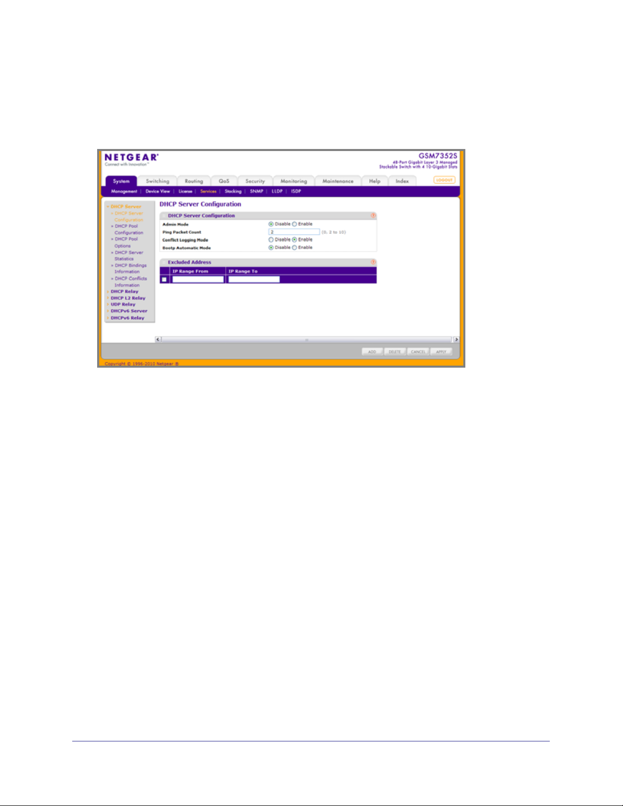
ProSafe® Gigabit L3 Managed Stackable Switches Software Administration Manual
DHCP Server Configuration
To display the DHCP Server Configuration page, click System > Services > DHCP Server>
DHCP Server Configuration. A screen similar to the following displays.
To enable or disable DHCP service:
1. Use Admin Mode to specify whether the DHCP Service is to be Enabled or Disabled.
Default value is Disable.
2. Use Ping Packet Count to specify the number of packets a server sends to a Pool address
to check for duplication as part of a ping operation. Default value is 2. Valid Range is (0, 2 to
10). Setting the value to 0 will disable the function.
3. Use Conflict Logging Mode to specify whether conflict logging on a DHCP Server is to be
Enabled or Disabled. Default value is Enable.
4. Use Bootp Automatic Mode to specify whether Bootp for dynamic pools is to be Enabled
or Disabled. Default value is Disable.
5. Click CANCEL to cancel the configuration on the screen. Resets the data on the screen to
the latest value of the switch.
6. Click APPLY to send the updated configuration to the switch. Configuration changes take
effect immediately.
52 | Chapter 2. Configuring System Information
Page 53

ProSafe® Gigabit L3 Managed Stackable Switches Software Administration Manual
Excluded Address Configuration
1. Use the IP Range From field to specify the low address if you want to exclude a range
of addresses. Specify the address to be excluded in case you want to exclude a single
address.
2. Use the IP Range To field to specify the high address if you want to exclude a range of
addresses. To exclude a single address, enter the same IP address as specified in IP range
from or leave as 0.0.0.0.
3. Click ADD to add the exclude addresses configured on the screen to the switch.
4. Click DELETE to delete the exclude address from the switch.
Chapter 2. Configuring System Information | 53
Page 54

ProSafe® Gigabit L3 Managed Stackable Switches Software Administration Manual
DHCP Pool Configuration
To display the DHCP Pool Configuration page, click System > Services > DHCP Server>
DHCP Pool Configuration. A screen similar to the following displays.
The following table describes the DHCP Pool Configuration fields.
Table 2-17.
Field Description
Pool Name* For a user with read/write permission, this field would
show names of all the existing pools along with an
additional option “Create”. When the user selects
“Create” another text box “Pool Name” appears
where the user may enter name for the Pool to be
created. For a user with read only permission, this
field would show names of the existing pools only.
Pool Name This field appears when the user with read-write
permission has selected “Create” in the Drop Down
list against Pool Name*. Specifies the Name of the
Pool to be created. Pool Name can be up to 31
characters in length.
54 | Chapter 2. Configuring System Information
Page 55

ProSafe® Gigabit L3 Managed Stackable Switches Software Administration Manual
Table 2-17.
Field Description
Type of Binding Specifies the type of binding for the pool.
• Unallocated
• Dynamic
• Manual
Network Address Specifies the subnet address for a DHCP address of
a dynamic pool.
Network Mask Specifies the subnet number for a DHCP address of
a dynamic pool. Either Network Mask or Prefix
Length can be configured to specify the subnet mask
but not both.
Network Prefix Length Specifies the subnet number for a DHCP address of
a dynamic pool. Either Network Mask or Prefix
Length can be configured to specify the subnet mask
but not both. Valid Range is (0 to 32)
Client Name Specifies the Client Name for DHCP manual Pool.
Hardware Address Specifies the MAC address of the hardware platform
of the DHCP client.
Hardware Address Type Specifies the protocol of the hardware platform of the
DHCP client. Valid types are ethernet and ieee802.
Default value is ethernet.
Client ID Specifies the Client Identifier for DHCP manual Pool.
Host Number Specifies the IP address for a manual binding to a
DHCP client. Host can be set only if at least one
among of Client Identifier or Hardware Address is
specified. Deleting Host would delete Client Name,
Client ID, Hardware Address for the Manual Pool and
set the Pool Type to Unallocated.
Host Mask Specifies the subnet mask for a manual binding to a
DHCP client. Either Host Mask or Prefix Length can
be configured to specify the subnet mask but not
both.
Host Prefix Length Specifies the subnet mask for a manual binding to a
DHCP client. Either Host Mask or Prefix Length can
be configured to specify the subnet mask but not
both. Valid Range is (0 to 32)
Lease Time Can be selected as “Infinite” to specify lease time as
Infinite or “Specified Duration” to enter a specific
lease period. In case of dynamic binding infinite
implies a lease period of 60 days and In case of
manual binding infinite implies indefinite lease
period. Default Value is “Specified Duration”.
Chapter 2. Configuring System Information | 55
Page 56

ProSafe® Gigabit L3 Managed Stackable Switches Software Administration Manual
Table 2-17.
Field Description
Days Specifies the Number of Days of Lease Period. This
field appears only if the user has specified “Specified
Duration” as the Lease time. Default Value is 1. Valid
Range is (0 to 59)
Hours Specifies the Number of Hours of Lease Period. This
field appears only if the user has specified “Specified
Duration” as the Lease time. Valid Range is (0 to 22)
Minutes Specifies the Number of Minutes of Lease Period.
This field appears only if the user has specified
“Specified Duration” as the Lease time. Valid Range
is (0 to 86399)
Default Router Addresses Specifies the list of Default Router Addresses for the
pool. The user may specify up to 8 Default Router
Addresses in order of preference.
DNS Server Addresses Specifies the list of DNS Server Addresses for the
pool. The user may specify up to 8 DNS Server
Addresses in order of preference.
NetBIOS Name Server Addresses Specifies the list of NetBIOS Name Server
Addresses for the pool. The user may specify up to 8
NetBIOS Name Server Addresses in order of
preference.
NetBIOS Node Type Specifies the NetBIOS node type for DHCP clients:
• b-node Broadcast
• p-node Peer-to-Peer
• m-node Mixed
• h-node Hybrid
Next Server Address Specifies the Next Server Address for the pool.
Domain Name Specifies the domain name for a DHCP client.
Domain Name can be up to 255 characters in length.
Bootfile Specifies the name of the default boot image for a
DHCP client. File Name can be up to 128 characters
in length.
1. Use ADD to create the Pool Configuration.
2. Use APPLY to change the Pool Configuration. Sends the updated configuration to the
switch. Configuration changes take effect immediately.
3. Use DELETE to delete the Pool. This field is not visible to a user with read only permission.
56 | Chapter 2. Configuring System Information
Page 57

ProSafe® Gigabit L3 Managed Stackable Switches Software Administration Manual
DHCP Pool Options
To display the DHCP Pool Options page, click System > Services > DHCP Server> DHCP
Pool Options. A screen similar to the following displays.
1. Use Pool Name to select the Pool Name.
2. Option Code specifies the Option Code configured for the selected Pool.
3. Use Option Type to specify the Option Type against the Option Code configured for the
selected pool:
• ASCII
• Hex
• IP Address
4. Option Value specifies the Value against the Option Code configured for the selected pool.
5. Click ADD to add a new Option Code for the selected pool.
6. Click DELETE to delete the Option Code for the selected pool.
Chapter 2. Configuring System Information | 57
Page 58

ProSafe® Gigabit L3 Managed Stackable Switches Software Administration Manual
DHCP Server Statistics
To display the DHCP Server Statistics page, click System > Services > DHCP Server>
DHCP Server Statistics. A screen similar to the following displays.
58 | Chapter 2. Configuring System Information
Page 59

ProSafe® Gigabit L3 Managed Stackable Switches Software Administration Manual
The following table describes the DHCP Server Statistics fields.
Table 2-18.
Field Description
Automatic Bindings Specifies the number of Automatic Bindings on the
DHCP Server.
Expired Bindings Specifies the number of Expired Bindings on the
DHCP Server.
Malformed Messages Specifies the number of the malformed messages.
DHCPDISCOVER Specifies the number of DHCPDISCOVER
messages received by the DHCP Server.
DHCPREQUEST Specifies the number of DHCPREQUEST messages
received by the DHCP Server.
DHCPDECLINE Specifies the number of DHCPDECLINE messages
received by the DHCP Server.
DHCPRELEASE Specifies the number of DHCPRELEASE messages
received by the DHCP Server.
DHCPINFORM Specifies the number of DHCPINFORM messages
received by the DHCP Server.
DHCPOFFER Specifies the number of DHCPOFFER messages
sent by the DHCP Server.
DHCPACK Specifies the number of DHCPACK messages sent
by the DHCP Server.
DHCPNAK Specifies the number of DHCPNAK messages sent
by the DHCP Server.
Chapter 2. Configuring System Information | 59
Page 60

ProSafe® Gigabit L3 Managed Stackable Switches Software Administration Manual
DHCP Bindings Information
To display the DHCP Bindings Information page, click System > Services > DHCP Server>
DHCP Bindings Information. A screen similar to the following displays.
1. Choose:
• All Dynamic Bindings to specify all dynamic bindings to be deleted.
• Specific Dynamic Binding to specify specific dynamic binding to be deleted.
The following table describes the DHCP Bindings Information fields.
Table 2-19.
Field Description
IP Address Specifies the Client's IP Address.
Hardware Address Specifies the Client's Hardware Address.
Lease Time Left Specifies the Lease time left in Days, Hours and
Minutes dd:hh:mm format.
Type Specifies the Type of Binding: Dynamic / Manual.
60 | Chapter 2. Configuring System Information
Page 61

ProSafe® Gigabit L3 Managed Stackable Switches Software Administration Manual
DHCP Conflicts Information
To display the DHCP Conflicts Information page, click System > Services > DHCP Server>
DHCP Conflicts Information. A screen similar to the following displays.
1. Choose:
• All Address Conflicts to specify all address conflicts to be deleted.
• Specific Address Conflict to specify a specific dynamic binding to be deleted.
The following table describes the DHCP Conflicts Information fields.
Table 2-20.
Field Description
IP Address Specifies the IP Address of the host as recorded on
the DHCP server.
Detection Method Specifies the manner in which the IP address of the
hosts were found on the DHCP Server.
Detection Time Specifies the time when the conflict was detected in
N days NNh:NNm:NNs format with respect to the
system up time.
Chapter 2. Configuring System Information | 61
Page 62

ProSafe® Gigabit L3 Managed Stackable Switches Software Administration Manual
DHCP Relay
To display the DHCP Relay page, click System > Services> DHCP Relay. A screen similar to
the following displays.
DHCP Relay Configuration
1. Use Maximum Hop Count to enter the maximum number of hops a client request can
take before being discarded. The range is (1 to 16). The default value is 4.
2. Use Admin Mode to select enable or disable radio button. When you select 'enable' DHCP
requests will be forwarded to the IP address you entered in the 'Server Address' field.
3. Use Minimum Wait Time to enter a Minimum Wait Time in seconds. This value will be
compared to the time stamp in the client's request packets, which should represent the time
since the client was powered up. Packets will only be forwarded when the time stamp
exceeds the minimum wait time. The range is (0 to 100).
4. Use Circuit ID Option Mode to enable or disable Circuit ID Option mode. If you select
'enable' Relay Agent options will be added to requests before they are forwarded to the
server and removed from replies before they are forwarded to clients.
62 | Chapter 2. Configuring System Information
Page 63

ProSafe® Gigabit L3 Managed Stackable Switches Software Administration Manual
DHCP Relay Status
The following table describes the DHCP Relay Status fields.
Table 2-21.
Field Description
Requests Received The total number of DHCP requests received from all
clients since the last time the switch was reset.
Requests Relayed The total number of DHCP requests forwarded to the
server since the last time the switch was reset.
Packets Discarded The total number of DHCP packets discarded by this
Relay Agent since the last time the switch was reset.
Chapter 2. Configuring System Information | 63
Page 64

ProSafe® Gigabit L3 Managed Stackable Switches Software Administration Manual
DHCP L2 Relay
From the DHCP L2 Relay link, you can access the following pages:
• DHCP L2 Relay Global Configuration on page 64
• DHCP L2 Relay Interface Configuration on page 65
• DHCP L2 Relay Interface Statistics on page 66s
DHCP L2 Relay Global Configuration
To display the DHCP L2 Relay Global Configuration page, click System > Services > DHCP
L2 Relay> DHCP L2 Relay Global Configuration. A screen similar to the following displays.
DHCP L2 Relay Global Configuration
1. Use Admin Mode to enable or disable the DHCP L2 Relay on the switch. The default is
Disable.
DHCP L2 Relay VLAN Configuration
1. VLAN ID shows the VLAN ID configured on the switch.
2. Use Admin Mode to enable or disable the DHCP L2 Relay on the selected VLAN.
3. Use Circuit ID Mode to enable or disable the Circuit ID suboption of DHCP Option-82.
4. Use Remote ID String to specify the Remote ID when Remote ID mode is enabled.
64 | Chapter 2. Configuring System Information
Page 65

ProSafe® Gigabit L3 Managed Stackable Switches Software Administration Manual
DHCP L2 Relay Interface Configuration
To display the DHCP L2 Relay Interface Configuration page, click System > Services >
DHCP L2 Relay> DHCP L2 Relay Interface Configuration. A screen similar to the following
displays.
1. Use Admin Mode to enable or disable the DHCP L2 Relay on the selected interface.
Default is disable.
2. Use 82 Option Trust Mode to enable or disable an interface to be trusted for DHCP L2
Relay (Option-82) received.
Chapter 2. Configuring System Information | 65
Page 66

ProSafe® Gigabit L3 Managed Stackable Switches Software Administration Manual
DHCP L2 Relay Interface Statistics
To display the DHCP L2 Relay Interface Statistics page, click System > Services > DHCP L2
Relay> DHCP L2 Relay Interface Statistics. A screen similar to the following displays.
The following table describes the DHCP L2 Relay Interface Statistics fields.
Table 2-22.
Field Description
Interface Shows the interface from which the DHCP message
is received.
UntrustedServerMsgsWithOpt82 Shows the number of DHCP message with option82
received from an untrusted server.
UntrustedClientMsgsWithOpt82 Shows the number of DHCP message with option82
received from an untrusted client.
TrustedServerMsgsWithoutOpt82 Shows the number of DHCP message without
option82 received from a trusted server.
TrustedClientMsgsWithoutOpt82 Shows the number of DHCP message without
option82 received from a trusted client.
66 | Chapter 2. Configuring System Information
Page 67

ProSafe® Gigabit L3 Managed Stackable Switches Software Administration Manual
UDP Relay
From the UDP Relay link, you can access the following pages:
• UDP Relay Global Configuration on page 67
• UDP Relay Interface Configuration on page 69
UDP Relay Global Configuration
To display the UDP Relay Global Configuration page, click System > Services > UDP Relay>
UDP Relay Global Configuration. A screen similar to the following displays.
1. Use Admin Mode to enable or disable the UDP Relay on the switch. The default value
is disable.
2. Use Server Address to specify the UDP Relay Server Address in x.x.x.x format.
3. Use UDP Port to specify the UDP Destination Port. These ports are supported:
• DefaultSet - Relay UDP port 0 packets. This is specified if no UDP port is selected
when creating the Relay server.
• dhcp -Relay DHCP (UDP port 67) packets.
• domain - Relay DNS (UDP port 53) packets.
• isakmp - Relay ISAKMP (UDP port 500) packets.
• mobile-ip - Relay Mobile IP (UDP port 434) packets
• nameserver - Relay IEN-116 Name Service (UDP port 42) packets
• netbios-dgm - Relay NetBIOS Datagram Server (UDP port 138) packets
• netbios-ns - Relay NetBIOS Name Server (UDP port 137) packets
• ntp - Relay network time protocol (UDP port 123) packets.
• pim-auto-rp - Relay PIM auto RP (UDP port 496) packets.
• rip - Relay RIP (UDP port 520) packets
• tacacs - Relay TACACS (UDP port 49) packet
Chapter 2. Configuring System Information | 67
Page 68

ProSafe® Gigabit L3 Managed Stackable Switches Software Administration Manual
• tftp - Relay TFTP (UDP port 69) packets
• time - Relay time service (UDP port 37) packets
• Other - If this option is selected, the UDP Port Other Value is enabled. This option
permits a user to enter their own UDP port in UDP Port Other Value.
4. Use UDP Port Other Value to specify a UDP Destination Port that lies between 0 and
65535.
5. Click ADD to create an entry in UDP Relay Table with the specified configuration.
6. Click DELETE to remove all entries or a specified one from UDP Relay Table.
The following table describes the UDP Relay Global Configuration fields.
Table 2-23.
Field Description
Hit Count Show the number of UDP packets hitting the UDP
port
68 | Chapter 2. Configuring System Information
Page 69

ProSafe® Gigabit L3 Managed Stackable Switches Software Administration Manual
UDP Relay Interface Configuration
To display the UDP Relay Interface Configuration page, click System > Services > UDP
Relay> UDP Relay Interface Configuration. A screen similar to the following displays.
1. Use Interface to select an Interface to be enabled for the UDP Relay.
2. Use Server Address to specify the UDP Relay Server Address in x.x.x.x format.
3. Use UDP Port to specify UDP Destination Port. The following ports are supported:
• DefaultSet - Relay UDP port 0 packets. This is specified if no UDP port is selected
when creating a Relay server.
• dhcp - Relay DHCP (UDP port 67) packets.
• domain - Relay DNS (UDP port 53) packets.
• isakmp - Relay ISAKMP (UDP port 500) packets.
• mobile-ip - Relay Mobile IP (UDP port 434) packets
• nameserver - Relay IEN-116 Name Service (UDP port 42) packets
• netbios-dgm - Relay NetBIOS Datagram Server (UDP port 138) packets
• netbios-ns - Relay NetBIOS Name Server (UDP port 137) packets
• ntp - Relay network time protocol (UDP port 123) packets.
• pim-auto-rp - Relay PIM auto RP (UDP port 496) packets.
• rip - Relay RIP (UDP port 520) packets
• tacacs - Relay TACACS (UDP port 49) packet
• tftp - Relay TFTP (UDP port 69) packets
• time - Relay time service (UDP port 37) packets
• Other - If this option is selected, the UDP Port Other Value is enabled. This option
permits the user to enter their own UDP port in UDP Port Other Value.
4. Use UDP Port Other Value to specify UDP Destination Port that lies between 0 and 65535.
Chapter 2. Configuring System Information | 69
Page 70

ProSafe® Gigabit L3 Managed Stackable Switches Software Administration Manual
5. Use Discard to enable/disable dropping of matched packets. Enable can be chosen only
when a user enters 0.0.0.0 IP address. Discard mode can be set to Disable when user adds
a new entry with a non-zero IP address.
6. Click ADD to create an entry in UDP Relay Table with the specified configuration.
7. Click DELETE to remove all entries or a specified one from UDP Relay Interface
Configuration Table.
The following table describes the UDP Relay Interface Configuration fields.
Table 2-24.
Field Description
Hit Count Show the number of UDP packets hitting the UDP
port.
70 | Chapter 2. Configuring System Information
Page 71

ProSafe® Gigabit L3 Managed Stackable Switches Software Administration Manual
DHCPv6 Server
From the DHCPv6 Server link, you can access the following pages:
• DHCPv6 Server Configuration on page 71
• DHCPv6 Pool Configuration on page 72
• DHCPv6 Prefix Delegation Configuration on page 73
• DHCPv6 Interface Configuration on page 75
• DHCPv6 Bindings Information on page 76
• DHCPv6 Server Statistics on page 77
DHCPv6 Server Configuration
To display the DHCPv6 Server Configuration page, click System > Services > DHCPv6
Server> DHCPv6 Server Configuration. A screen similar to the following displays.
1. Use Admin Mode to specify DHCPv6 operation on the switch. Value is enabled or
disabled.
2. Use Relay Option to specify Relay Agent Information Option value. The values allowed are
between 54 to 65535. The default value is 54.
3. Use Remote-id Sub-option to specify the Relay Agent Information Option Remote-ID
Sub-option type value. The values allowed are between 1 and 65535. The default value is 1.
Chapter 2. Configuring System Information | 71
Page 72

ProSafe® Gigabit L3 Managed Stackable Switches Software Administration Manual
DHCPv6 Pool Configuration
To display the DHCPv6 Pool Configuration page, click System > Services > DHCPv6
Server> DHCPv6 Pool Configuration. A screen similar to the following displays.
1. Pool Name - For a user with read/write permission, this field would show names of all
the existing pools along with an additional option “Create”. When the user selects
“Create” another text box “Pool Name” appears where the user may enter name for the
Pool to be created. For a user with read only permission, this field would show names of
the existing pools only.
2. Use Pool Name to specify a unique name for DHCPv6 pool. It may be up to 31
alphanumeric characters.
3. Use Domain Name to specify a DNS domain server name. It may be up to 255
alphanumeric characters.
4. Use DNS Server Address to specify the IPv6 address of a DNS server.
72 | Chapter 2. Configuring System Information
Page 73

ProSafe® Gigabit L3 Managed Stackable Switches Software Administration Manual
DHCPv6 Prefix Delegation Configuration
To display the DHCPv6 Prefix Delegation Configuration page, click System > Services >
DHCPv6 Server> DHCPv6 Prefix Delegation Configuration. A screen similar to the following
displays.
Chapter 2. Configuring System Information | 73
Page 74

ProSafe® Gigabit L3 Managed Stackable Switches Software Administration Manual
1. Use Pool Name to select one DHCPv6 pool to be configured.
2. Use Prefix/Prefix Length to specify the delegated IPv6 prefix.
3. Use DUID to identify the client's unique duid value. The format is xx:xx:xx:xx:xx:xx.
RFC3315 defines three types:
a. Link-layer address plus time:
- 00:01:hardware type:time:link-layer address
- hardware type - 16 bit hardware type reserved by IANA. 1 means an Ethernet
device.
- time: 32-bit unsigned integer - The time in seconds when this DUID was
generated since 00:00:00 1/1/2000.
- link-layer address - The link layer address of a device generating the DUID.
b. Vendor-assigned unique ID based on Enterprise Number:
- 00:02:enterprise-number:identifier
- enterprise-number - 32-bit integer reserved by IANA.
- identifier - Variable length data for each vendor
c. Link-layer address:
- 00:03:hardware type:link-layer address
- hardware type - 16 bit hardware type reserved by IANA. 1 means an Ethernet
device.
- link-layer address - The link layer address of a device generating the DUID.
4. Use Client Name to specify client's name. This is useful for logging or tracing only. It may be
up to 31 alphanumeric characters.
5. Use Valid Lifetime to specify the valid lifetime in seconds for delegated prefix.
6. Use Prefer Lifetime to specify the prefer lifetime in seconds for delegated prefix.
7. Click ADD to add a new delegated prefix for the selected pool.
8. Click DELETE to delete the delegated prefix for the selected pool.
74 | Chapter 2. Configuring System Information
Page 75

ProSafe® Gigabit L3 Managed Stackable Switches Software Administration Manual
DHCPv6 Interface Configuration
To display the DHCPv6 Prefix Delegation Configuration page, click System > Services >
DHCPv6 Server> DHCPv6 Interface Configuration. A screen similar to the following
displays.
1. Use Interface to specify the interface configured for DHCPv6 server functionality.
2. Use Admin Mode to specify DHCPv6 mode to configure server functionality. DHCPv6
server and DHCPv6 relay functions are mutually exclusive.
3. Use Pool Name to specify the DHCPv6 pool containing stateless and/or prefix delegation
parameters.
4. Use the optional Rapid Commit parameter to allow abbreviated exchange between the
client and server.
5. Use Preference to specify the preference value used by clients to determine preference
between multiple DHCPv6 servers. The values allowed are between 0 to 4294967295. The
default value is 0.
Chapter 2. Configuring System Information | 75
Page 76

ProSafe® Gigabit L3 Managed Stackable Switches Software Administration Manual
DHCPv6 Bindings Information
To display the DHCPv6 Bindings Information page, click System > Services > DHCPv6
Server> DHCPv6 Bindings Information. A screen similar to the following displays.
The following table describes the DHCPv6 Bindings Information fields.
Table 2-25.
Field Description
Client Address Specifies the IPv6 address of the client associated
with the binding.
Client Interface Specifies the interface number where the client
binding occurred.
Client DUID Specifies client's DHCPv6 unique identifier.
Prefix/PrefixLength Specifies the IPv6 address and mask length for
delegated prefix associated with this binding.
Prefix Type Specifies the type of prefix associated with this
binding.
Expiry Time Specifies the number of seconds until the prefix
associated with a binding will expire.
Valid Lifetime Specifies the valid lifetime value in seconds of the
prefix associated with a binding.
Prefer Lifetime Specifies the preferred lifetime value in seconds of
the prefix associated with a binding.
76 | Chapter 2. Configuring System Information
Page 77

ProSafe® Gigabit L3 Managed Stackable Switches Software Administration Manual
DHCPv6 Server Statistics
To display the DHCPv6 Server Statistics page, click System > Services > DHCPv6 Server>
DHCPv6 Server Statistics. A screen similar to the following displays.
1. Use Interface to select the interface for which data is to be displayed or configured. On
selecting all, data will be shown for all interfaces.
Chapter 2. Configuring System Information | 77
Page 78

ProSafe® Gigabit L3 Managed Stackable Switches Software Administration Manual
The following table describes the DHCPv6 Server Statistics fields.
Table 2-26.
Field Description
Messages Received Specifies the aggregate of all interface level statistics
for received messages.
Total DHCPv6 Packets Received Specifies the total number of Packets Received.
DHCPv6 Solicit Packets Received Specifies the number of Solicits.
DHCPv6 Request Packets Received Specifies the number of Requests.
DHCPv6 Confirm Packets Received Specifies the number of Confirms.
DHCPv6 Renew Packets Received Specifies the number of Renews.
DHCPv6 Rebind Packets Received Specifies the number of Rebinds.
DHCPv6 Release Packets Received Specifies the number of Releases.
DHCPv6 Decline Packets Received Specifies the number of Declines.
DHCPv6 Inform Packets Received Specifies the number of Informs.
DHCPv6 Relay-forward Packets Received Specifies the number of Relay forwards.
DHCPv6 Relay-reply Packets Received Specifies the number of Relay Replies.
DHCPv6 Malformed Packets Received Specifies the number of Malformed Packets.
Received DHCPv6 Packets Discarded Specifies the number of Packets Discarded.
Messages Sent Specifies the aggregate of all interface level statistics
for messages sent.
Total DHCPv6 Packets Sent Specifies the total number of Packets Transmitted.
DHCPv6 Advertisement Packets Transmitted Specifies the number of Advertisements.
DHCPv6 Reply Packets Transmitted Specifies the number of Replies.
DHCPv6 Reconfig Packets Transmitted Specifies the number of Reconfigurations.
DHCPv6 Relay-forward Packets Transmitted Specifies the number of Relay forwards.
DHCPv6 Relay-reply Packets Transmitted Specifies the number of Relay Replies.
78 | Chapter 2. Configuring System Information
Page 79

ProSafe® Gigabit L3 Managed Stackable Switches Software Administration Manual
DHCPv6 Relay
To display the DHCPv6 Relay page, click System > Services > DHCPv6 Relay. A screen
similar to the following displays.
1. Use Interface to specify interface configured for DHCPv6 Relay functionality.
2. Use Admin Mode to specify DHCPv6 mode to configure DHCPv6 Relay functionality.
DHCPv6 server and DHCPv6 relay functions are mutually exclusive.
3. Use Relay Interface to specify an interface to reach a relay server.
4. Use Destination IP Address to specify an IPv6 Address to reach a relay server.
5. Use Remote ID to specify the relay agent information option. Remote ID needs to be
derived from the DHCPv6 server DUID and the relay interface number, or it can be specified
as a user defined string.
Stacking
From the Stacking link, you can access the following pages:
• Basic on page 80
• Advanced on page 83
Chapter 2. Configuring System Information | 79
Page 80

ProSafe® Gigabit L3 Managed Stackable Switches Software Administration Manual
Basic
From the Basic link, you can access the following pages:
• Stack Configuration on page 80
Stack Configuration
This page moves the Primary Management Unit functionality from one unit to another. Upon
execution, the entire stack (including all interfaces in the stack) is unconfiugred and
reconfigured with the configuration on the new Primary Management Unit. After the reload is
complete, all stack management capability must be performed on the new Primary
Management Unit. To preserve the current configuration across a stack move, save the
current configuration to the NVRAM before performing the stack move. A stack move causes
all routes and layer 2 addresses to be lost. The administrator is prompted to confirm the
management move.
80 | Chapter 2. Configuring System Information
Page 81

ProSafe® Gigabit L3 Managed Stackable Switches Software Administration Manual
To display the Stack Configuration page, click System > Stacking > Basic> Stack
Configuration. A screen similar to the following displays.
1. Use Management Unit Selected to select the unit to be managed unit and click APPLY
to move the management to the selected unit.
2. Unit ID displays the list of units of the stack. Details of the selected unit are displayed. There
is also an ADD option visible only to Admin users which can be used to pre-configure new
members of the stack.
3. Use Switch Type to specify the type of switch hardware when creating a new switch in the
stack.
4. Admin Management Preference is a 2-byte field that indicates whether the administrator
wants this unit to become a management unit in preference to another unit. The default
value for this setting is one. If the preference level is set to zero then the device cannot
become a management unit. This field is non-configurable for users with read-only access.
5. Click ADD to add a unit to the stack with the specific switch type.
6. Click DELETE to remove the selected unit from the stack.
Chapter 2. Configuring System Information | 81
Page 82

ProSafe® Gigabit L3 Managed Stackable Switches Software Administration Manual
The following table describes the Stack Configuration fields.
Table 2-27.
Field Description
Hardware Management Preference The hardware management preference of the switch.
The hardware management preference can be
disabled or unassigned.
Switch Status Displays the status of the selected unit. The possible
values are:
• OK
• Unsupported
• Code Mismatch
• Config Mismatch
• Not Present
Management Status Displays whether the selected switch is the
management unit or a normal stacking member or on
standby.
The following table describes the Basic Stack Status fields.
Table 2-28.
Field Description
Unit ID Unit Id of the specific switch.
Switch Description The description for the unit can be configured by the
user.
Serial Number The unique box serial number for this switch.
Up Time Displays the relative time since the last reboot of the
switch.
Configured Model Identifier This field displays the model type assigned by the
device manufacturer to identify the device.
Plugged-in Model Identifier This field displays the model type assigned by the
device manufacturer to identify the plugged-in
device.
Expected Code Type This field indicates the expected code type on this
unit.
Running Code Version This field indicates the detected version of code on
this unit.
Code Version in Flash Displays the Release number and version number of
the code stored in flash.
Click REFRESH to update the information on the page.
82 | Chapter 2. Configuring System Information
Page 83

ProSafe® Gigabit L3 Managed Stackable Switches Software Administration Manual
Advanced
From the Advanced link, you can access the following pages:
• Stack Configuration on page 80
• Stack Port Configuration on page 85
• Stack Port Diagnostics on page 86
Stack Configuration
This page moves the Primary Management Unit functionality from one unit to another. Upon
execution, the entire stack (including all interfaces in the stack) is unconfiugred and
reconfigured with the configuration on the new Primary Management Unit. After the reload is
complete, all stack management capability must be performed on the new Primary
Management Unit. To preserve the current configuration across a stack move, please save
the current configuration to the nvram before performing the stack move. A stack move
causes all routes and layer 2 addresses to be lost. The administrator is prompted to confirm
the management move.
To display the Stack Configuration page, click System > Stacking > Advanced> Stack
Configuration. A screen similar to the following displays.
1. Use Management Unit Selected to select the unit to be managed unit and click APPLY
to move the management to the selected unit.
2. Unit ID - Displays the list of units of the stack. Details of the selected unit are displayed.
There is also an ADD option visible only to Admin users which can be used to pre-configure
new members of the stack.
3. Use Switch Type to specify the type of switch hardware when creating a new switch in the
stack.
4. Admin Management Preference is a 2-byte field that indicates whether the administrator
wants this unit to become a management unit in preference to another unit. The default
value for this setting is one. If the preference level is set to zero then the device cannot
become a management unit. This field is non-configurable for users with read-only access.
5. Click ADD to add a unit to the stack with the specific switch type.
6. Click DELETE to remove the selected unit from the stack.
Chapter 2. Configuring System Information | 83
Page 84

ProSafe® Gigabit L3 Managed Stackable Switches Software Administration Manual
The following table describes the Stack Configuration fields.
Table 2-29.
Field Description
Hardware Management Preference The hardware management preference of the switch.
The hardware management preference can be
disabled or unassigned.
Switch Status Displays the status of the selected unit. The possible
values are:
• OK
• Unsupported
• Code Mismatch
• Config Mismatch
• Not Present
Management Status Displays whether the selected switch is the
management unit or a normal stacking member or on
standby.
Stack Status
The following table describes the Stack Status fields.
Table 2-30.
Field Description
Unit ID Unit Id of the specific switch.
Switch Description The description for the unit can be configured by the
user.
Serial Number The unique box serial number for this switch.
Up Time Displays the relative time since the last reboot of the
switch.
Configured Model Identifier This field displays the model type assigned by the
device manufacturer to identify the device.
Plugged-in Model Identifier This field displays the model type assigned by the
device manufacturer to identify the plugged-in
device.
Expected Code Type This field indicates the expected code type on this
unit.
Running Code Version This field indicates the detected version of code on
this unit.
Code Version in Flash Displays the Release number and version number of
the code stored in flash.
84 | Chapter 2. Configuring System Information
Page 85

ProSafe® Gigabit L3 Managed Stackable Switches Software Administration Manual
Stack Port Configuration
To display the Stack Port Configuration page, click System > Stacking > Advanced> Stack
Port Configuration. A screen similar to the following displays.
1. Configured Stack Mode - Specify the operating mode of the port to be either ethernet or
stacking. The default value is set to stacking.
The following table describes Stack Port Configuration fields.
Table 2-31.
Field Description
Unit ID Displays the unit.
Port Displays the stackable interfaces on the given unit.
Running Stack Mode Displays the run-time mode of the stackable
interface.
Link Status Displays the link status (UP/DOWN) of the port.
Link Speed (Gbps) Displays the maximum speed of the stacking port.
Transmit Data Rate (Mbps) Displays the approximate transmit rate on the
stacking port.
Total Transmit Errors Displays the total number of errors in transmit
packets since boot. The counter may wrap.
Receive Data Rate (Mbps) Displays the approximate receive rate on the
stacking port.
Total Receive Errors Displays the total number of errors in receive packets
since boot. The counter may wrap.
Chapter 2. Configuring System Information | 85
Page 86

ProSafe® Gigabit L3 Managed Stackable Switches Software Administration Manual
Stack Port Diagnostics
This page displays the diagnostics for all the stackable interfaces in the given stack.
To display the Stack Port Diagnostics page, click System > Stacking > Advanced> Stack
Port Diagnostics. A screen similar to the following displays.
The following table describes the Stack Port Diagnostics fields.
Table 2-32.
Field Definition
Port Displays the stackable interface on the given unit.
Port Diagnostics Info Displays three text fields (80 character strings)
populated by the driver containing debug and status
information.
PoE
From the PoE link under the System tab, you can view and configure PoE settings for the
switch
From the PoE link, you can access the following pages:
• Basic on page 86
• Advanced on page 89
Basic
From the Basic link, you can access the following pages:
• PoE Configuration on page 87
86 | Chapter 2. Configuring System Information
Page 87

ProSafe® Gigabit L3 Managed Stackable Switches Software Administration Manual
PoE Configuration
Use the PoE Configuration page to view global PoE power information and to configure PoE
SNMP trap settings.
To display this page, click System PoE Basic PoE Configuration. A screen similar to the
following displays.
1. Unit - Displays the Current PoE Unit. You can change the PoE Unit by selecting another
unit ID listed here.
2. Use System Usage Threshold to set a threshold level at which a trap is sent if consumed
power is greater than threshold power.
3. Use Power Management Mode to describe or control the power management algorithm
used by the PSE to deliver power to the requesting PDs. "Static" value means that power
allocated for each port depends on the type of power threshold configured on the port.
"Dynamic" value means that power consumption of each port is measured and calculated in
real-time.
4. Use Auto Reset Mode to specify Enable or Disable. When set to "Enable", the PSE port is
reset without administrator intervention whenever a fault condition occurs. When set to
"Disable", the administrator has to reset the PSE port whenever a fault condition is detected.
5. Use Traps to enable or disable activation of PoE traps by selecting the corresponding check
box. The factory default is enabled.
Table 3.
Field Definition
Firmware Version Version of the PoE controller's firmware image.
Power Status Indicates the power status.
Chapter 2. Configuring System Information | 87
Page 88

ProSafe® Gigabit L3 Managed Stackable Switches Software Administration Manual
Table 3.
Field Definition
Total Power (Main AC) Maximum amount of power the system can deliver to
all ports when the PoE unit is powered up by Main
AC Supply.
Total Power (RPS) Maximum amount of power the system can deliver to
all ports when the PoE unit is powered up by RPS
unit.
Power Source The power source. There are two possible power
sources: Main AC or RPS.
Threshold Power System can powerup one port, if consumed power is
less than this power, i.e., Consumed power can be
between Nominal and Threshold Power values. The
threshold power value is effected by changing
System Usage Threshold.
Consumed Power Total amount of a power which is currently being
delivered to all ports.
88 | Chapter 2. Configuring System Information
Page 89

ProSafe® Gigabit L3 Managed Stackable Switches Software Administration Manual
Advanced
From the Advanced link, you can access the following pages:
• PoE Configuration on page 89
• PoE Port Configuration on page 91
PoE Configuration
Use the PoE Configuration page to view global PoE power information and to configure PoE
SNMP trap settings.
To display this page, click System PoE Advanced PoE Configuration. A screen similar
to the following displays.
1. Unit - Displays the Current PoE Unit. You can change the PoE Unit by selecting another
unit ID listed here.
2. Use System Usage Threshold to set a threshold level at which a trap is sent if consumed
power is greater than threshold power.
3. Use Power Management Mode to describe or control the power management algorithm
used by the PSE to deliver power to the requesting PDs. "Static" value means that power
allocated for each port depends on the type of power threshold configured on the port.
"Dynamic" value means that power consumption of each port is measured and calculated in
real-time.
4. Use Auto Reset Mode to specify Enable or Disable. When set to "Enable", the PSE port is
reset without administrator intervention whenever a fault condition occurs. When set to
"Disable", the administrator has to reset the PSE port whenever a fault condition is detected.
5. Use Traps to enable or disable activation of PoE traps by selecting the corresponding check
box. The factory default is enabled.
Chapter 2. Configuring System Information | 89
Page 90

ProSafe® Gigabit L3 Managed Stackable Switches Software Administration Manual
Table 4.
Field Definition
Firmware Version Version of the PoE controller's firmware image.
Power Status Indicates the power status.
Total Power (Main AC) Maximum amount of power the system can deliver to
all ports when the PoE unit is powered up by Main
AC Supply.
Total Power (RPS) Maximum amount of power the system can deliver to
all ports when the PoE unit is powered up by RPS
unit.
Power Source The power source. There are two possible power
sources: Main AC or RPS.
Threshold Power System can powerup one port, if consumed power is
less than this power, i.e., Consumed power can be
between Nominal and Threshold Power values. The
threshold power value is effected by changing
System Usage Threshold.
Consumed Power Total amount of a power which is currently being
delivered to all ports.
90 | Chapter 2. Configuring System Information
Page 91

ProSafe® Gigabit L3 Managed Stackable Switches Software Administration Manual
PoE Port Configuration
Use the PoE Port Configuration page to configure per-port PoE settings.
To display this page, click System
PoE Advanced PoE Port Configuration. A screen
similar to the following displays.
1. Unit - Displays the Current PoE Unit. You can change the PoE Unit by selecting another
unit ID listed here.
2. Use Admin Mode to enable/disable the ability of the port to deliver a power.
3. Use Port Priority to determine which ports can deliver power when total power delivered by
the system crosses a certain threshold. The switch may not be able to supply a power to all
connected devices. Priority is used to determine which ports can supply power. The lower
numbered port which is one of the ports of the same priority will have a higher priority.
• low - Low priority.
• high - High priority.
• critical - Critical priority.
4. Use High Power Mode to specify one of the following:
• Disable value means that a port is powered in the IEEE 802.3af mode.
• Legacy value means that a port is powered using high-inrush current, used by legacy
PDs whose power requirement is more than 15W from powerup.
• Pre-802.3at value means that a port is powered in the IEEE 802.3af mode initially,
switched to the high-power IEEE 802.3at mode before 75msec. This mode needs to
be used, if PD is NOT performing Layer 2 Classification Or PSE is performing 2-Event
Layer 1 Classification.
• 802.3at value means that a port is powered in the IEEE 802.3at mode, i.e., if class
detected by PSE is not the class4, then the PSE port will not power up the PD.
Chapter 2. Configuring System Information | 91
Page 92

ProSafe® Gigabit L3 Managed Stackable Switches Software Administration Manual
5. Use Power Limit Type to describe or control the maximum power that a port can deliver.
"Dot3AF" value means that the port power limit is equal to the dot3af class of the PD
attached. "User" value means that the port power limit is equal to the value specified by
"Power Limit". "None" value means that there is no power provided to the port.
6. Use Power Limit to define the maximum power which can be delivered by a port.
7. Use Detection Type to describe a PD detection mechanism performed by the PSE port:
• None value means that no detection is done.
• Legacy Only value means that only legacy capacitive detection scheme is used.
• 802.3af 4point Only value means that the IEEE 802.3af 4point detection scheme is
used.
• 802.3af 4point and Legacy value means that the IEEE 802.3af 4point detection
scheme is used and when it fails to detect a connected PD, legacity capacity
detection is used.
• 802.3af 2point Only value means that the IEEE 802.3af 2point detection scheme is
used.
• 802.3af 2point and Legacy value means that the IEEE 802.3af 2point detection
scheme is used and when it fails to detect a connected PD, legacity capacity
detection is used.
8. Click RESET to forcibly reset the PSE port.
Table 5.
Field Definition
Port The interface for which data is to be displayed or
configured.
High Power Enabled when particular port supports High Power
Mode.
Max Power The maximum power in Watts that can be provided
by the port.
Class The class of the Powered Device (PD) defines the
range of power a PD is drawing from the system.
Class definitions:
• 0 - 0.44-12.95(watts)
• 1 - 0.44-3.83(watts)
• 2 - 0.44-6.48(watts)
• 3 - 0.44-12.95(watts)
• 4 - 0.44-25.5(watts)
Output Voltage Current voltage being delivered to device in volts.
Output Current Current being delivered to device in mA.
Output Power Current power being delivered to device in Watts.
92 | Chapter 2. Configuring System Information
Page 93

ProSafe® Gigabit L3 Managed Stackable Switches Software Administration Manual
Table 5.
Field Definition
Status Operational status of the port PD detection.
• Disabled - indicates no power being delivered.
• DeliveringPower - indicates power is being drawn
by device.
• Fault - indicates a problem with the port.
• Test - indicates port is in test mode.
• otherFault - indicates port is idle due to error
condition.
• Searching - indicates port is not in one of the
above states.
Fault Status Describes the error description when the PSE port is
in fault status. "No Error" value specifies that the
PSE port is not in any error state. "MPS Absent"
value specifies that the PSE port has detected an
absence of main power supply. "Short" value
specifies that the PSE port has detected a short
circuit condition. "Overload" value specifies that the
pd connected to the PSE port had tried to provide
more power than it is permissible by the hardware.
"Power Denied" value specifies that the PSE port
has been denied power because of shortage of
power or due to administrative action.
SNMP
From SNMP link under the System tab, you can configure SNMP settings for SNMP V1/V2
and SNMPv3.
From the SNMP link, you can access the following pages:
• SNMPV1/V2 on page 93
• SNMP V3 on page 101
SNMPV1/V2
The pages under the SNMPV1/V2 menu allow you to configure SNMP community
information, traps, and trap flags.
From the SNMP V1/V2 link, you can access the following pages:
• Community Configuration on page 94
• Trap Configuration on page 96
• Trap Flags on page 97
• Supported MIBs on page 99
Chapter 2. Configuring System Information | 93
Page 94

ProSafe® Gigabit L3 Managed Stackable Switches Software Administration Manual
Community Configuration
By default, two SNMP Communities exist:
• Private, with Read/Write privileges and status set to Enable.
• Public, with Read Only privileges and status set to Enable.
These are well-known communities. Use this page to change the defaults or to add other
communities. Only the communities that you define using this page will have access to the
switch using the SNMPv1 and SNMPv2c protocols. Only those communities with read/write
level access can be used to change the configuration using SNMP.
Use this page when you are using the SNMPv1 and SNMPv2c protocol. If you want to use
SNMP v3 you should use the User Accounts menu.
94 | Chapter 2. Configuring System Information
Page 95

ProSafe® Gigabit L3 Managed Stackable Switches Software Administration Manual
To display this page, click System SNMP SNMP V1/V2 Community Configuration. A
screen similar to the following displays.
1. Use Community Name to reconfigure an existing community, or to create a new one.
Use this pull-down menu to select one of the existing community names, or select
'Create' to add a new one. A valid entry is a case-sensitive string of up to 16 characters.
2. Client Address - Taken together, the Client Address and Client IP Mask denote a range of
IP addresses from which SNMP clients may use that community to access this device. If
either (Client Address or IP Mask) value is 0.0.0.0, access is allowed from any IP address.
Otherwise, every client's address is ANDed with the mask, as is the Client Address, and, if
the values are equal, access is allowed. For example, if the Client Address and Client IP
Mask parameters are 192.168.1.0/255.255.255.0, then any client whose address is
192.168.1.0 through 192.168.1.255 (inclusive) will be allowed access. To allow access from
only one station, use a Client IP Mask value of 255.255.255.255, and use that machine's IP
address for Client Address.
3. Client IP Mask - Taken together, the Client Address and Client IP Mask denote a range of
IP addresses from which SNMP clients may use that community to access this device. If
either (Client Address or IP Mask) value is 0.0.0.0, access is allowed from any IP address.
Otherwise, every client's address is ANDed with the mask, as is the Client Address, and, if
the values are equal, access is allowed. For example, if the Client Address and Client IP
Mask parameters are 192.168.1.0/255.255.255.0, then any client whose IP address is
192.168.1.0 through 192.168.1.255 (inclusive) will be allowed access. To allow access from
only one station, use a Client IP Mask value of 255.255.255.255, and use that machine's IP
address for Client Address.
4. Use Access Mode to specify the access level for this community by selecting Read/Write or
Read Only from the pull-down menu.
5. Use Status to specify the status of this community by selecting Enable or Disable from the
pull-down menu. If you select enable, the Community Name must be unique among all valid
Community Names or the set request will be rejected. If you select disable, the Community
Name will become invalid.
6. Click ADD to add the currently selected community to the switch.
7. Click DELETE to delete the currently selected Community Name.
Chapter 2. Configuring System Information | 95
Page 96

ProSafe® Gigabit L3 Managed Stackable Switches Software Administration Manual
Trap Configuration
This page displays an entry for every active Trap Receiver. To access this page, click
System
1. To add a host that will receive SNMP traps, enter trap configuration information in the
SNMP SNMP V1/V2 Trap Configuration.
available fields described below, and then click Add.
a. Community Name - Enter the community string for the SNMP trap packet to be sent
to the trap manager. This may be up to 16 characters and is case sensitive.
b. Version - Select the trap version to be used by the receiver from the pull down
menu:
• SNMP v1 - Uses SNMP v1 to send traps to the receiver.
• SNMP v2 - Uses SNMP v2 to send traps to the receiver.
c. Protocol - Select the protocol to be used by the receiver from the pull down menu.
Select the IPv4 if the receiver's address is IPv4 address or IPv6 if the receiver's
address is IPv6.
d. Address - Enter the IPv4 address in x.x.x.x format or IPv6 address in
xxxx:xxxx:xxxx:xxxxx:xxxx:xxxx:xxxx:xxxx or a hostname starting with an alphabet to
receive SNMP traps from this device. Length of address can not exceed 158
characters.
e. Status - Select the receiver's status from the pull-down menu:
• Enable - Send traps to the receiver
• Disable - Do not send traps to the receiver.
2. To modify information about an existing SNMP recipient, select the check box next to the
recipient, change the desired fields, and then click Apply. Configuration changes take effect
immediately.
3. To delete a recipient, select the check box next to the recipient and click Delete.
4. Click Cancel to cancel the configuration on the screen and reset the data on the screen to
the latest value of the switch.
96 | Chapter 2. Configuring System Information
Page 97

ProSafe® Gigabit L3 Managed Stackable Switches Software Administration Manual
Trap Flags
Use the Trap Flags page to enable or disable traps. When the condition identified by an
active trap is encountered by the switch, a trap message is sent to any enabled SNMP Trap
Receivers, and a message is written to the trap log.
To access the Trap Flags page, click System
SNMP SNMP V1/V2 Trap Flags.
Chapter 2. Configuring System Information | 97
Page 98

ProSafe® Gigabit L3 Managed Stackable Switches Software Administration Manual
To configure the trap flags:
1. Use Authentication to enable or disable activation of authentication failure traps by
selecting the corresponding radio button. The factory default is enabled.
2. Use Link Up/Down to enable or disable activation of link status traps by selecting the
corresponding radio button. The factory default is enabled.
3. Use Multiple Users to enable or disable activation of multiple user traps by selecting the
corresponding radio button. The factory default is enabled. This trap is triggered when the
same user ID is logged into the switch more than once at the same time (either via telnet or
the serial port).
4. Use Spanning Tree to enable or disable activation of spanning tree traps by selecting the
corresponding radio button. The factory default is enabled.
5. Use ACL to enable or disable activation of ACL traps by selecting the corresponding radio
button. The factory default is disabled.
6. Use DVMRP to enable or disable activation of DVMRP traps by selecting the corresponding
radio button. The factory default is disabled.
7. Use PIM to enable or disable activation of spanning tree traps by selecting the
corresponding radio button. The factory default is disabled.
8. Use OSPF to enable or disable activation of OSPF traps by selecting the corresponding
radio button. The factory default is enabled. This field can be configured only if the OSPF
admin mode is enabled.
9. Click CANCEL to cancel the configuration on the screen. Resets the data on the screen to
the latest value of the switch.
10. Click APPLY to send the updated configuration to the switch. Configuration changes take
effect immediately.
98 | Chapter 2. Configuring System Information
Page 99

ProSafe® Gigabit L3 Managed Stackable Switches Software Administration Manual
Supported MIBs
This page displays all the MIBs supported by the switch. To access this page, click System
SNMP
SNMP V1/V2 Supported MIBs.
Chapter 2. Configuring System Information | 99
Page 100

ProSafe® Gigabit L3 Managed Stackable Switches Software Administration Manual
The following table describes the SNMP Supported MIBs Status fields.
Table 2-33.
Field Description
Name The RFC number if applicable and the name of the
MIB.
Description The RFC title or MIB description.
100 | Chapter 2. Configuring System Information
 Loading...