

Page 1

WIRESPEED™ ETHERNET BRIDGE (MODEL 6000)
WIRESPEED™ DUAL CONNECT BRIDGE (MODEL6110)
W
IRESPEED™ DUAL CONNECT NAT ROUTER (MODEL 6100)
USER GUIDE
Copyright © 2006 Westell, Inc.
May 2006
030-300233 Rev. A
Page 2

User Guide
Westell (Models 6000, 6100, 6110)
This User Guide provides information about the WireSpeed Ethernet Bridge (Model 6000), the WireSpeed Dual
Connect Bridge (Model 6110), and the WireSpeed Dual Connect NAT Router (6100). The following table outlines
the sections of this document that apply to each Westell product. To determine which product you have, view the
label that is affixed to the bottom of the modem. The label contains a model number that identifies your product.
Section Model 6000 Model 6110 Model 6100
1 Product Description x x x
2 Safety Instructions x x x
3 Regulatory Information x x x
4 Networking Requirements x x x
5 Installing the Hardware x x x
6 Installing the USB Drivers x x
7 Configuring Your Router for Internet Connection x
8 Setting Up Macintosh OS X x
9 Setting Up Advanced Configuration x
10 Home Menu x
11 Status Menu x
12 Configuration Menu x
13 Setting Up Advanced Service Configuration x
14 Maintenance Menu x
15 Troubleshooting (System Self Test) Menu x
16 NAT Services x
17 Product Specifications x x x
18 Appendix A-Help x
19 Appendix B-Hardware Features x x x
20 Appendix C-Diagnostic Software x x see note*
21 Technical Support Information x x x
22 Warranty Information x x x
23 Software License Agreement x x x
24 Publication Information x x x
*Note: The 6100 product has diagnostic capabilities internal to the device.
030-300233 Rev. A 2 May 2006
Page 3

User Guide
Westell (Models 6000, 6100, 6110)
TABLE OF CONTENTS
1.
PRODUCT DESCRIPTION (MODELS 6000, 6100, 6110)..................................................................................6
2. SAFETY INSTRUCTIONS (MODELS 6000, 6100, 6110)..................................................................................6
3. REGULATORY INFORMATION (MODELS 6000, 6100, 6110).......................................................................7
3.1 FCC Compliance Note...............................................................................................................................7
3.2 Canada Certification Notice.......................................................................................................................8
4. NETWORKING REQUIREMENTS (MODELS 6000, 6100, 6110).....................................................................9
5. INSTALLING THE HARDWARE (MODELS 6000, 6100, 6110).....................................................................10
5.1 Installation Requirements........................................................................................................................10
5.2 Before you begin......................................................................................................................................10
5.3 Microfilters..............................................................................................................................................10
5.4 Installations..............................................................................................................................................11
6. INSTALLING THE USB DRIVERS (MODELS 6100, 6110)............................................................................15
6.1 CD-ROM Installation:............................................................................................................................. 15
6.2 Installing the USB Drivers for Windows 98 SE ......................................................................................15
6.3 Installing the USB Drivers for Windows ME..........................................................................................21
6.4 Installing the USB Driver for Windows 2000.......................................................................................... 23
6.5 Installing the USB Driver for Windows XP ............................................................................................26
7. CONFIGURING YOUR ROUTER FOR INTERNET CONNECTION (MODEL 6100)...................................28
7.1 Setting Up an Account Profile.................................................................................................................28
7.2 Establishing a PPP Session......................................................................................................................32
7.3 Disconnecting a PPP Session...................................................................................................................34
8. SETTING UP MACINTOSH OS X (MODEL 6100)..........................................................................................36
8.1 Open the System Preference Screen ........................................................................................................36
8.2 Choose the Network Preferences.............................................................................................................36
8.3 Create a New Location.............................................................................................................................37
8.4 Name the New Location..........................................................................................................................37
8.5 Select the Ethernet Configuration............................................................................................................37
8.6 Check the IP Connection .........................................................................................................................38
8.7 Create a User Account.............................................................................................................................39
9. SETTING UP ADVANCED CONFIGURATION (MODEL 6100)....................................................................40
10. HOME..................................................................................................................................................................40
10.1 Setting Up Advanced Configuration........................................................................................................40
10.2 Adding Account Profiles..........................................................................................................................41
10.3 Edit Account Profiles...............................................................................................................................42
030-300233 Rev. A 3 May 2006
Page 4

User Guide
Westell (Models 6000, 6100, 6110)
STATUS...............................................................................................................................................................44
11.
11.1 Connection Summary...............................................................................................................................44
11.2 About .......................................................................................................................................................45
12. CONFIGURATION.............................................................................................................................................46
12.1 VC Configuration ....................................................................................................................................46
12.2 Editing the VC Configuration..................................................................................................................47
12.3 DNS Configuration..................................................................................................................................58
12.4 DHCP Configuration (Private LAN) .......................................................................................................60
12.5 Private LAN Configuration - Configuring NAT......................................................................................64
12.6 Public LAN Configuration-Multiple IP PassThrough .............................................................................66
12.7 Single Static IP Configuration .................................................................................................................69
12.8 Service Configuration..............................................................................................................................74
12.9 Firewall Configuration.............................................................................................................................83
12.10 ATM Loopbacks......................................................................................................................................86
12.11 Turbo TCP...............................................................................................................................................87
13. SETTING UP ADVANCE D SERVICE CONFIGURATION.............................................................................89
13.1 Port Forwarding Ranges of Ports.............................................................................................................90
13.2 Adding Port Forwarding Ports.................................................................................................................90
13.3 Port Forwarding Trigger Ports.................................................................................................................91
13.4 Adding Local Trigger Ports .....................................................................................................................92
13.5 Static NAT...............................................................................................................................................93
13.6 Enabling Static NAT................................................................................................................................94
13.7 Disabling Static NAT...............................................................................................................................95
14. MAINTENANCE.................................................................................................................................................97
14.1 Backup/Restore........................................................................................................................................97
14.2 Firewall Log.............................................................................................................................................98
14.3 Change Password.....................................................................................................................................99
14.4 Remote Access.......................................................................................................................................100
14.5 Update Device........................................................................................................................................101
15. TROUBLESHOOTING.....................................................................................................................................106
15.1 System Self Tests...................................................................................................................................106
15.2 Diagnostic Logs .....................................................................................................................................108
15.3 WAN VC Statistics................................................................................................................................110
15.4 Ethernet Statistics ..................................................................................................................................111
15.5 Transceiver Statistics .............................................................................................................................112
15.6 USB Port Statistics.................................................................................................................................113
15.7 LAN Statistics........................................................................................................................................114
030-300233 Rev. A 4 May 2006
Page 5

User Guide
Westell (Models 6000, 6100, 6110)
NAT SERVICES................................................................................................................................................115
16.
17. PRODUCT SPECIFICATIONS (MODELS 6000, 6100, 6110)........................................................................119
18. APPE N DI X A -HE LP (MO D EL 6100)..............................................................................................................121
19. APPE N DI X B-H ARD WARE FEATURES (MODELS 6000, 6100, 6110).......................................................134
19.1 LED Indicators.......................................................................................................................................134
19.2 Cable Connectors and Switch Locations................................................................................................135
19.3 Connector Descriptions..........................................................................................................................136
19.4 Pinout Descriptions................................................................................................................................136
20. APPENDIX C-DIAGNOSTIC SOFTWARE (MODELS 6000, 6110)..............................................................137
20.1 Installing Diagnostic Software for Windows.........................................................................................137
20.2 Uninstalling Diagnostic Software for Windows....................................................................................141
21. TECHNICAL SUPPORT INFORMATION (MODELS 6000, 6100, 6110) .....................................................143
22. WARR AN TY INFORMATION (MODELS 6000, 6100, 6110) .......................................................................143
23. SOFT WA RE LICEN SE AG R EEMENT ( M ODEL S 6000, 6100, 6110)...........................................................144
24. PUBLICATION INFORMATION.....................................................................................................................146
030-300233 Rev. A 5 May 2006
Page 6
User Guide
Westell (Models 6000, 6100, 6110)
1. PRODUCT DESCRIPTION
The Westell® Modem provides reliable, high-speed, Internet access to your existing home or office phone line.
Your ADSL connection is “always-on” ending the hassles of dial-up modems and busy signals. Installation is easy
... no tools ... no headaches. Simply connect the hardware, apply power, and perform the simple software
configuration for your Modem and you are on the Internet.
This Modem is capable of data rates hundreds of times faster than a traditional analog modem. But unlike analog
modems, Westell’s Modem allows you to use the same phone line for simultaneous voice/fax communications and
high-speed Internet access, eliminating the need for dedicated phone lines for voice and data needs.
2. SAFETY INSTRUCTIONS
• Never install any telephone wiring during a lightning storm.
Never install telephone jacks in wet locations unless the jack is specifically designed for wet locations.
•
Never touch non-insulated telephone wires or terminals unless the telephone line has been disconnected at
•
the network interface.
• Use caution when installing or modifying telephone lines.
WARNING
Risk of electric shock. Voltages up to 140 Vdc (with reference to
ground) may be present on telecommunications circuits.
030-300233 Rev. A 6 May 2006
Page 7

User Guide
Westell (Models 6000, 6100, 6110)
3. REGULATORY INFORMATION
3.1 FCC Compliance Note
This equipment has been tested and found to comply with the limits for a Class B digital device, pursuant to Part 15
of the Federal Communication Commission (FCC) Rules. These limits are designed to provide reasonable prot ect ion
against harmful interference in a residential installation. This equipment generates, uses, and can radiate radio
frequency energy, and if not installed and used in accordance with the instructions, may cause harmful interference
to radio communications. However, there is no guarantee that interference will not occur in a particular installation.
If this equipment does cause harmful interference to radio or television reception, which can be determined by
turning the equipment OFF and ON, the user is encouraged to try to correct the interference by one or more of the
following measures:
• Reorient or relocate the receiving antenna.
• Increase the separation between the equipment and the receiver.
• Connect the equipment to a different circuit from that to which the receiver is connected.
• Consult the dealer or an experienced radio/TV technician for help.
PART 68 - COMPLIANCE REGISTRATION
This equipment (Models 6000, 6100, 6110) complies with Part 68 of the FCC rules and the requirements adopted by
the ACTA. A label on the bottom of this equipment contains, among other information, the Ringer Equivalence
Number (REN) and the product identifier. For products approved after July 23, 2001 the product identifier is in the
format US:AAAEQ##TXXXX. The digits represented by ## are the REN without a decimal point (e.g. 03 is a REN
of 0.3). The REN is used to determine the number of devices that may be connected to a telephone line. For earlier
products, the REN is separately shown on the label. If requested, this number must be provided to the telephone
company.
Excessive RENs on a telephone line may result in the devices not ringing in response to an incoming call. In most,
but no all areas, the sum of RENs should not exceed five (5.0). To be certain of the number of devices that may be
connected to a line, as determined by the total RENs, contact the local telephone company.
This equipment is designated to connect to the telephone network or premises wiring using a compatible modular
jack that is Part 68 compliant. An FCC compliant telephone cord and modular plug is provided with the equipment.
See the Installation Information section of this User Guide for details.
A plug and jack used to connect this equipment to the premises wiring and telephone network must comply with the
applicable FCC Part 68 rules and requirements adopted by the ACTA. A compliant telephone cord and m odul ar plug
is provided with this product. It is designed to be connected to a compatible modular jack that is also compliant. See
installation instruction for details.
If this terminal equipment (Models 6000, 6100, 6110) causes harm to the telephone network, the telephone company
may request you to disconnect the equipment until the problem is resolved. The telephone company will notify you
in advance if temporary discontinuance of service is required. If advance notification is not practical, the telephone
company will notify you as soon as possible. You will be advised of your right to file a complaint with the FCC if
you believe such action is necessary.
If you experience trouble with this equipment (Models 6000, 6100, 6110), do not try to repair the equipment
yourself. The equipment cannot be repaired in the field and must be returned to the manufacturer. Repairs to
certified equipment should be coordinated by a representative, and designated by the supplier. Refer to section 12 in
this User Guide for further details.
030-300233 Rev. A 7 May 2006
Page 8

User Guide
The telephone company may make changes to their facilities, equipment, operations, or procedures that could affect
the operation of this equipment. If this happens, the telephone company will provide advance notice in order for you
to make the modifications necessary to maintain uninterrupted service.
If your home has specially wired alarm equipment connected to the telephone line, ensure that the installation of this
equipment (Models 6000, 6100, 6110) does not disable your alarm equipment. If you have questions about what will
disable alarm equipment, consult your telephone company or a qualified installer.
This equipment cannot be used on public coin phone service provided by the telephone company. Connection of this
equipment to party line service is subject to state tariffs.
Westell (Models 6000, 6100, 6110)
3.2 Canada Certification Notice
The Industry Canada label identifies certified equipment. This certification means that the equipment meets certain
telecommunications network protective, operations and safety requirements as prescribed in the appropriate
Terminal Equipment Technical Requirements document(s). The department does not guarantee the equipment will
operate to the user’s satisfaction.
This equipment meets the applicable Industry Canada Terminal Equipment Technical Specification. This is
confirmed by the registration number. The abbreviation, IC, before the registration number signifies that registration
was performed based on a Declaration of Conformity indicating that Industry Canada technical specification were
met. It does not imply that Industry Canada approved the equipment. The Ringer Equivalence Number (REN) is 0.0.
The Ringer Equivalence Number that is assigned to each piece of terminal equipment provides an indication of the
maximum number of terminals allowed to be connected to a telephone interface. The termination on an interface
may consist of any combination of devices subject only to the requirement that the sum of the Ringer Equivalence
Numbers of all the devices does not exceed five.
Before installing this equipment, users should ensure that it is permissible to be connected to the facilities of the
local Telecommunication Company. The equipment must also be installed using an acceptable method of
connection. The customer should be aware that compliance with the above conditions may not prevent degradation
of service in some situations. Connection to a party line service is subject to state tariffs. Contact the state public
utility commission, public service commission, or corporation commission for information.
If your home has specially wired alarm equipment connected to the telephone line, ensure that the installation of this
equipment (Models 6000, 6100, 6110) does not disable your alarm equipment. If you have questions about what will
disable alarm equipment, consult your telephone company or a qualified installer.
If you experience trouble with this equipment (Models 6000, 6100, 6110), do not try to repair the equipment
yourself. The equipment cannot be repaired in the field and must be returned to the manufacturer. Repairs to
certified equipment should be coordinated by a representative, and designated by the supplier. Refer to section 12 in
this User Guide for further details.
The termination on an interface may consist of any combination of devices subject only to the requirement that the
sum of the Ringer Equivalence Numbers of all the devices does not exceed five.
Users should ensure, for their own protection, that the electrical ground connections of the power utility, telephone
lines, and internal, metallic water pipe system, if present, are connected together. This precaution may be
particularly important in rural areas.
Users should not attempt to make such connections themselves, but should contact the
appropriate electrical inspection authority, or electrician, as appropriate.
030-300233 Rev. A 8 May 2006
CAUTION
Page 9
User Guide
Westell (Models 6000, 6100, 6110)
4. NETWORKING REQUIREMENTS
The following system specifications are required for optimum performance of the Modem via 10/100 Base-T or
USB installation.
MODEL
6000
6100
6110
6100
6110
CONNECTION
TYPE
ETHERNET
USB
MINIMUM SYSTEM REQUIREMENTS
• Pentium
® or equivalent and above class machines,
Macintosh
• Microsoft
® Windows® (98 SE, 2000, ME, NT 4.0, or XP) or
Macintosh® OS X installed
• Computer Operating System CD-ROM on hand
• Internet Explorer 4.x or Netscape Navigator 4.x or higher
• 64 MB RAM (128 MB recommended)
• 10 MB of free hard drive space
• TCP/IP Protocol stack installed
• 10/100 Base-T Network Interface Card (NIC)
• Pentium
• Microsoft
® or equivalent and above class machines
® Windows® 98 SE, 2000, ME, NT 4.0, or XP
installed
• Computer operating system CD-ROM on hand
• Internet Explorer 4.x or Netscape Navigator 4.x or higher
• 64 MB RAM (128 MB recommended)
• 10 MB of free hard drive space
• USB Version 1.0 or higher compliant bus
030-300233 Rev. A 9 May 2006
Page 10

User Guide
Westell (Models 6000, 6100, 6110)
5. INSTALLING THE HARDWARE
To obtain additional information on hardware features and installation, see Appendix B-Hardware Features.
5.1 Installation Requirements
To install the Westell Modem, you will need the following:
• A Network Interface Card (NIC) installed in your PC or
• An available USB port installed on your PC
• A DSL line (provided by your Internet service provider)
IMPORTANT: Please wait until you have received notification from your Internet service provider (ISP) that your
DSL line has been activated before installing the modem and software.
5.2 Before you begin
Make sure that your kit contains the following items:
Model 6000 Model 6100 and Model 6110
• Westell Modem
• Power Supply
• RJ-45 Ethernet cable (straight-through)
(yellow)
• RJ-11 Phone cable
• Westell CD-ROM containing User Guide in
PDF format
• Quick Start Guide
• Westell Modem
• Power Supply
• RJ-45 Ethernet cable (straight-through)
(yellow)
• USB cable (blue)
• RJ-11 Phone cable
• Westell CD-ROM containing USB software
drivers and User Guide in PDF format
• Quick Start Guide
5.3 Microfilters
ADSL signals must be blocked from reaching each telephone, answering machine, fax machine, computer modem
or any similar conventional device. Failure to do so may degrade telephone voice quality and ADSL performance.
Install a microfilter if you desire to use the DSL-equipped line jack for telephone, answering machine, fax machine
or other telephone device connections. Microfilter installation requires no tools or telephone rewiring. Just unplug
the telephone device from the baseboard or wall mount and snap in a microfilter, next snap in the telephone device.
You can purchase microfilters from your local electronics retailer, or contact the original provider of your DSL
equipment.
030-300233 Rev. A 10 May 2006
Page 11
User Guide
Westell (Models 6000, 6100, 6110)
5.4 Installations
This section explains the procedures for installing via 10/100 Base-T/Et hernet , USB, or combined Ethernet and USB
connection.
IMPORTANT:
1. Please wait until you have received notification from your Internet service provider (ISP) that your DSL line
has been activated before installing your Modem.
2. If you are using a Westell Modem in conjunction with an Ethernet Hub or Switch, refer to the manufacturer’s
instructions for proper installation and configuration.
3. Westell recommends the use of a surge suppressor to protect equipment attached to the AC power supply.
4. Refer to Appendix B for additional information on the modems’ LED states.
5.4.1 Installation via 10/100 Base-T Ethernet (Models 6000, 6100, 6110)
NOTE: Before you connect via 10/100 Base-T, you must have an available Ethernet card installed in your
computer. If your Ethernet card does not auto-negotiate, you must set it to half duplex. Refer to the Ethernet card
manufacturer’s instructions for installing and configuring your Ethernet card.
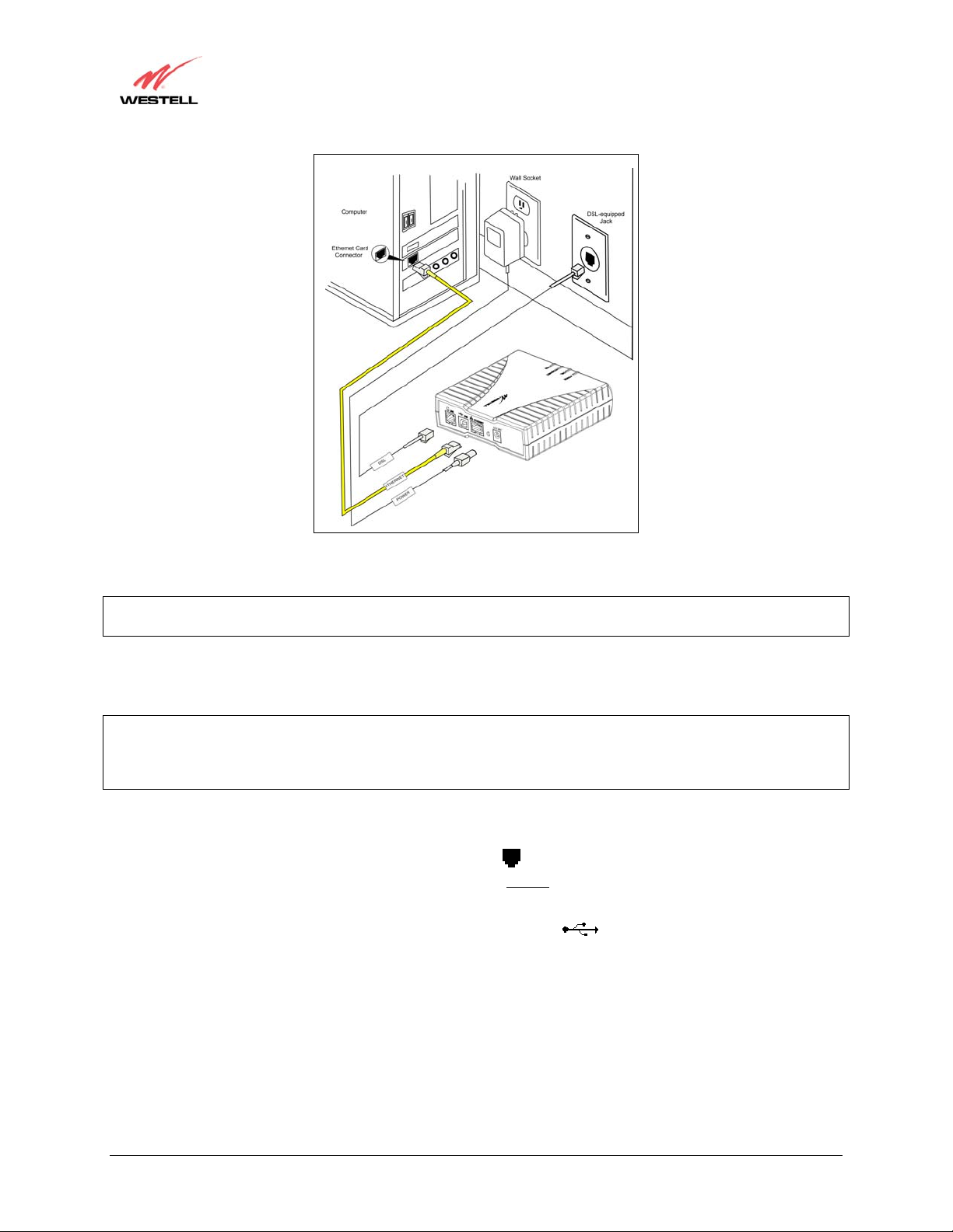
1. Connect the power supply cord to the power connector marked on the rear panel of the Modem. Plug
the other end of the power supply into an AC wall socket.
10.5 VAC
2. Connect the DSL phone cable from the jack marked
equipped telephone line jack on the wall. IMPORTANT: Do not
DSL on the rear panel of the Modem to the DSL-
use a DSL filter on this connection. You must
use the phone cord that was provided with the kit.
3. Connect the yellow Ethernet cable from the yellow Ethernet jack marked
ETHERNET on the rear panel
of the Modem to the Ethernet port on your computer.
4. Check to see if the Power LED is solid green. Solid green indicates that the modem power is ON.
5. Check to see if the DSL LED is solid green. If the DSL LED is solid green, the modem is functioning properly.
6. Check to see if the Ethernet LED is solid green. Solid green indicates that the Ethernet connection is
functioning properly.
For 6000 model users
7. Check the Power LED. Solid green indicates that the modem power is ON.
8. Check the Ready LED. Solid green indicates that the modem has synchronized with the ADSL line card.
9. Check the Link LED. Solid green indicates that the Ethernet connection is functioning properly.
10. Check the Activity LED. Solid green indicates that data is being sent or received on the Ethernet interface.
Congratulations! You have completed the Ethernet hardware installation. No software installation is required when
using only an Ethernet connection. Refer to your Internet service provider’s instructions for installing subscriber
software and connecting to the Internet. If you have a Model 6100 product, please proceed to section 7 to configure
your Router for Internet connection.
030-300233 Rev. A 11 May 2006
Page 12
User Guide
Westell (Models 6000, 6100, 6110)
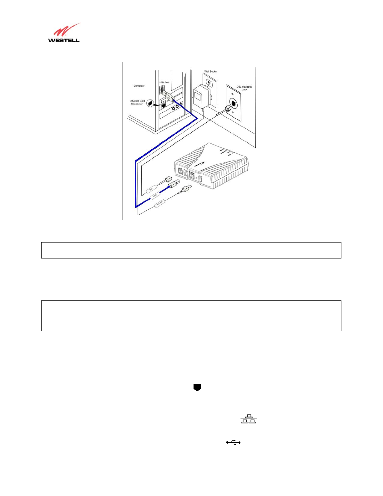
Figure 1. Connection via 10/100 Base-T Ethernet
NOTE: The modem features shown in Figure 1 apply to the Model 6100 and Model 6110 products. The Model
6000 product has only Ethernet.
5.4.2 Installation via USB (Models 6100, 6110)
IMPORTANT: If you are installing the modem via USB, you mu st first install the USB drivers on your computer.
Complete the instructions in section 6 to install the USB drivers, and th en return to this section and complete the
following instructions. The USB installation will not function for Macintosh computers. Macintosh users must
install the modem via Ethernet connection. See section 5.4.1 for installation instructions via Ethernet.
1. Connect the power supply cord to the power connector marked on the rear panel of the Modem. Plug
the other end of the power supply into an AC wall socket.
2. Connect the DSL phone cable from the connector marked
equipped telephone line jack on the wall. IMPORTANT: Do not use a DSL filter on this connection. You must
use the phone cord that was provided with the Modem kit.
3. Connect the blue USB cable from the blue USB connector marked
to the USB port on the PC.
4. Check to see if the Power LED is solid green. Solid green indicates that the modem power is ON.
5. Check to see if the DSL LED is solid green. If the DSL LED is solid green, the modem is functioning properly.
6. Check to see if th e USB LED is solid green. Solid green indicates that the USB connection is functioning
properly.
10.5 VAC
DSL on the rear panel of the Modem to the DSL-
USB on the rear panel of the Modem
Congratulations! You have completed the USB hardware installation for Models 6100 and 6110. Refer to your
Internet service provider’s instructions for installing subscriber software and connecting to the Internet. If you have
a Model 6100 product, please proceed to section 7 to configure your Router for Internet connection.
030-300233 Rev. A 12 May 2006
Page 13
User Guide
Westell (Models 6000, 6100, 6110)
Figure 2. Connection via USB
NOTE: The modem features shown in Figure 2 apply to the Model 6100 and Model 6110 products. The Model
6000 product has only Ethernet.
5.4.3 Installation via 10/100 Base-T Ethernet and USB (Simultaneous
Installation for Models 6100 and 6110)
IMPORTANT: If you are installing the modem via USB, you mu st first install the USB drivers on your computer.
Complete the instructions in section 6 to install the USB drivers, and th en return to this section and complete the
following instructions. The USB installation will not function for Macintosh computers. Macintosh users must
install the modem via Ethernet connection. See section 5.4.1 for installation instructions via Ethernet.
Models 6100 and 6110 support simultaneous use of 10/100 Base-T Ethernet and USB ports. The following
instructions explain how to install your Modem for simultaneous use of Ethernet and USB ports. Refer to the
illustrations in Figure 1 and Figure 2 for hardware connections.
1. Connect the power supply cord to the power connector marked on the rear panel of the Modem. Plug
the other end of the power supply into an AC wall socket.
2. Connect the DSL phone cable from connector marked
equipped telephone line jack on the wall. IMPORTANT: Do not
use the phone cord that was provided with the Modem kit.
10.5 VAC
DSL on the rear panel of the Modem to the DSL-
use a DSL filter on this connection. You must
3. Connect the yellow Ethernet cable from the yellow Ethernet jack marked
ETHERNET on the rear panel of
the Modem to the Ethernet port on your computer.
4. Connect the blue USB cable from the blue USB connector marked
USB on the rear panel of the Modem
to the USB port on the PC.
030-300233 Rev. A 13 May 2006
Page 14

User Guide
Westell (Models 6000, 6100, 6110)
5. Check to see if the Power LED is solid green. Solid green indicates that the modem power is ON.
6. Check to see if the DSL LED is solid green. If the DSL LED is solid green, the modem is functioning properly.
7. Check to see if th e USB LED is solid green. Solid green indicates that the USB connection is functioning
properly.
8. Check to see if the Ethernet LED is solid green. Solid green indicates that the Ethernet connection is
functioning properly.
Congratulations! You have completed the simultaneous hardware (Ethernet and USB) installation for Models 6100
and 6110. Refer to your Internet service provider’s instructions for installing subscriber software and connecting to
the Internet. If you have a Model 6100 product, please proceed to section 7 to configure your Router for Internet
connection.
030-300233 Rev. A 14 May 2006
Page 15
User Guide
Westell (Models 6000, 6100, 6110)
6. INSTALLING THE USB DRIVERS (MODELS 6100, 6110)
If you are using only Ethernet ports, USB driver installation is not necessary. The Microsoft® Plug and Play autodetect feature recognizes when new hardware has been installed. After you connect the Modem to the PC, the
Modem will be detected automatically.
Before you begin the USB driver software installation, determine which operating system is installed on your PC.
Then, follow the instructions that match your operating system (e.g., for Microsoft Windows 98, refer to the
instructions in section 6.2). Next, begin the USB driv er software installation. When the installation has completed,
proceed to section 7. The following table provides a quick reference to the USB software driver instructions.
Your Operating System Refer to this section for USB driver instructions
Windows 98 SE 6.2
Windows ME 6.3
Windows 2000 6.4
Windows XP 6.5
6.1 CD-ROM Installation:
1. Place the CD-ROM that you received in the Modem kit into the CD-ROM drive of the PC that is connected to
the USB port.
2. Go to the USB driver installation section that matches your operating system and follow the procedures outlined
in that section.
3. Verify the connection to the computer by observing the state of the USB LED. Once the USB drivers have been
installed, the USB LED should be solid green. Solid green indicates a USB connection has been established. For
additional information on LED states, refer to Appendix B-Hardware Features.
6.2 Installing the USB Drivers for Windows 98 SE
IMPORTANT: Confirm that the CD-ROM provided with the modem kit is inserted in the appropriate drive before
continuing this installation.
NOTE: The actual information displayed in the USB screens may vary according to product.
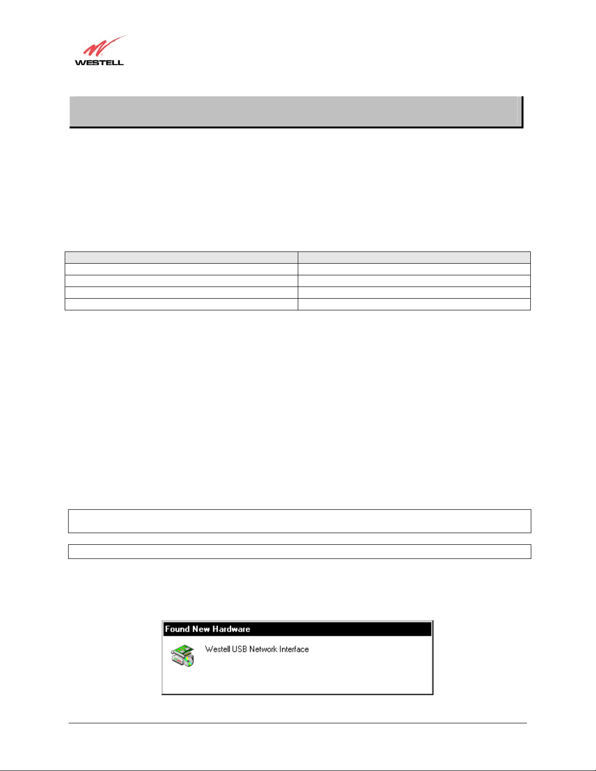
1. Windows 98 SE: After you have connected the Modem to your PC, the Found New Hardware window
appears (Figure 3). In a few moments, the Add New Hardware Wizard window will open (Figure 4). Click
Next to continue.
Figure 3. Windows 98 SE
030-300233 Rev. A 15 May 2006
Page 16
User Guide
Westell (Models 6000, 6100, 6110)
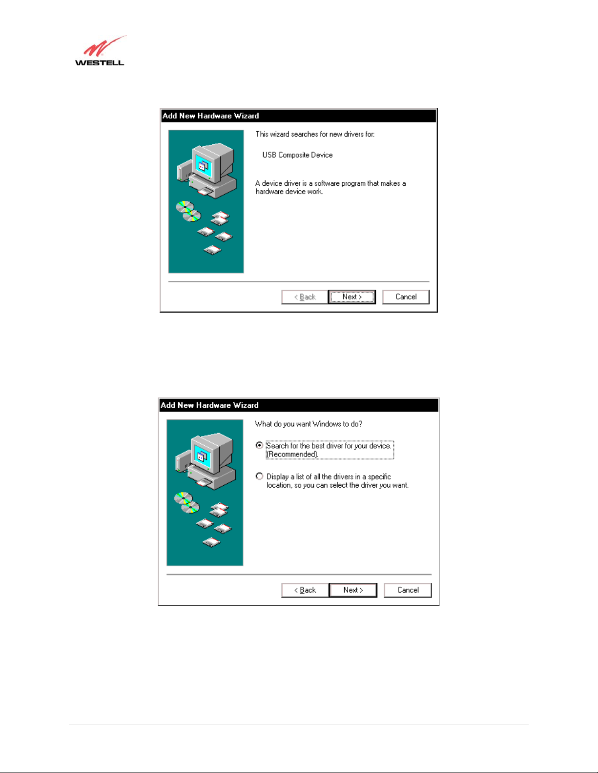
Figure 4. Windows 98 SE
2. Windows 98 SE: Click the option button for Search for the best driver for your device. (Recommended).
See Figure 5. Click Next to continue.
Figure 5. Windows 98 SE
030-300233 Rev. A 16 May 2006
Page 17
User Guide
Westell (Models 6000, 6100, 6110)
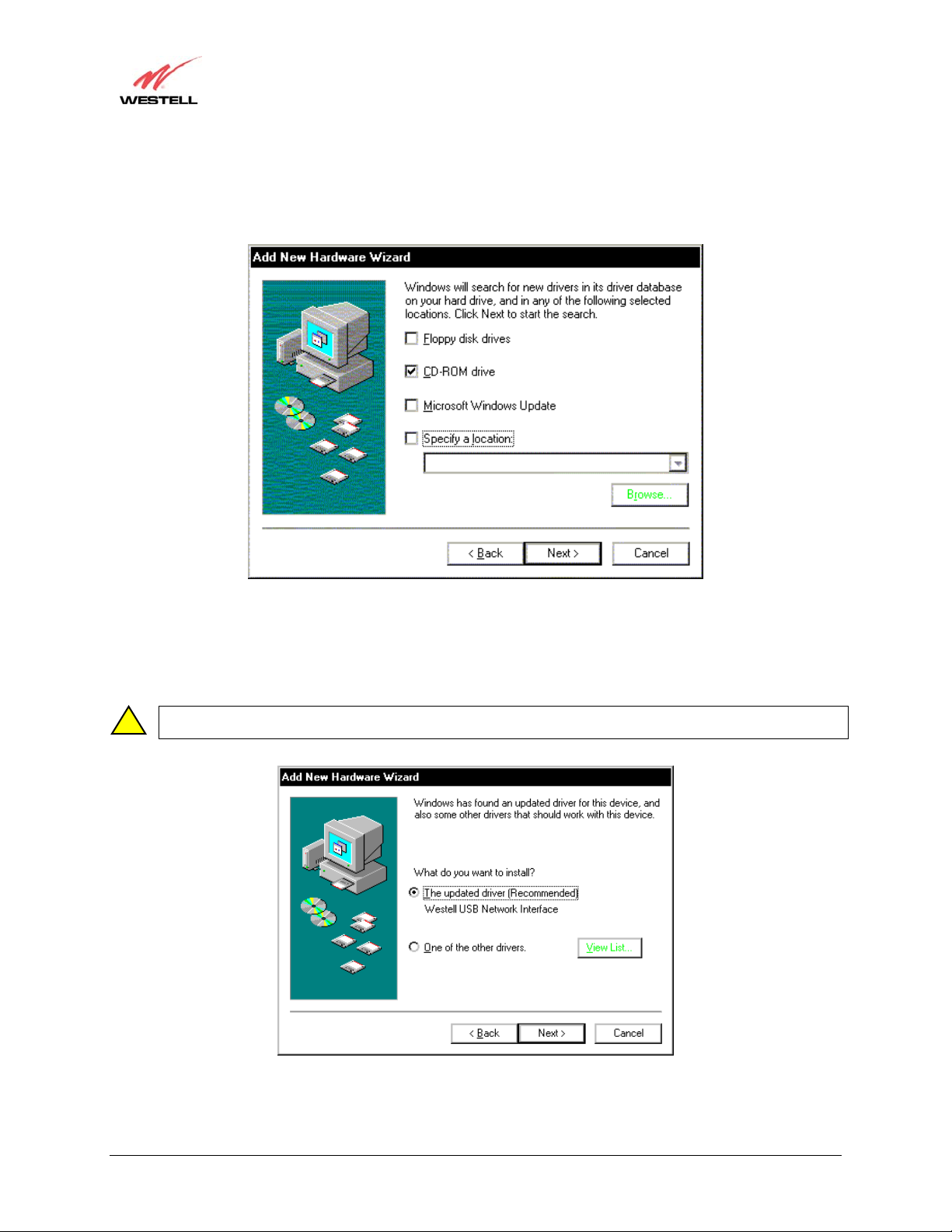
3. Windows 98 SE: Select CD-ROM drive option. See Figure 6. Click Next. Windows will search for the driver.
Figure 6. Windows 98 SE
4. Windows 98 SE: Select option button The updated driver (Recommended) Westell USB Network
Interface. See Figure 7. Click Next to continue
Note: If Figure 8 does not appear at this step, and Figure 9 appears with the text ‘USB Composite device’, ‘C:\Windows\Inf\USB.Inf’,
!
do not continue. Click Back to Step 3 and specify the location of the Westell CD-ROM.
Figure 7. Windows 98 SE
030-300233 Rev. A 17 May 2006
Page 18
User Guide
Westell (Models 6000, 6100, 6110)
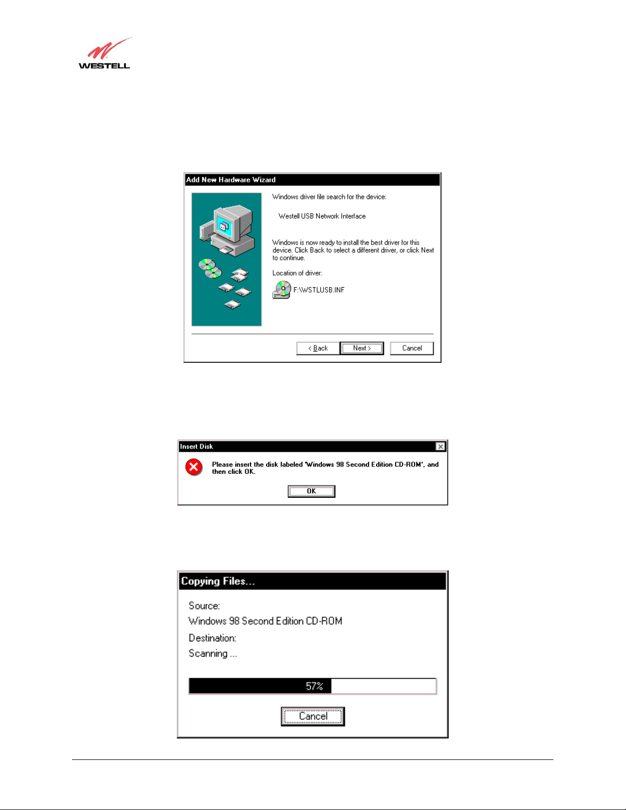
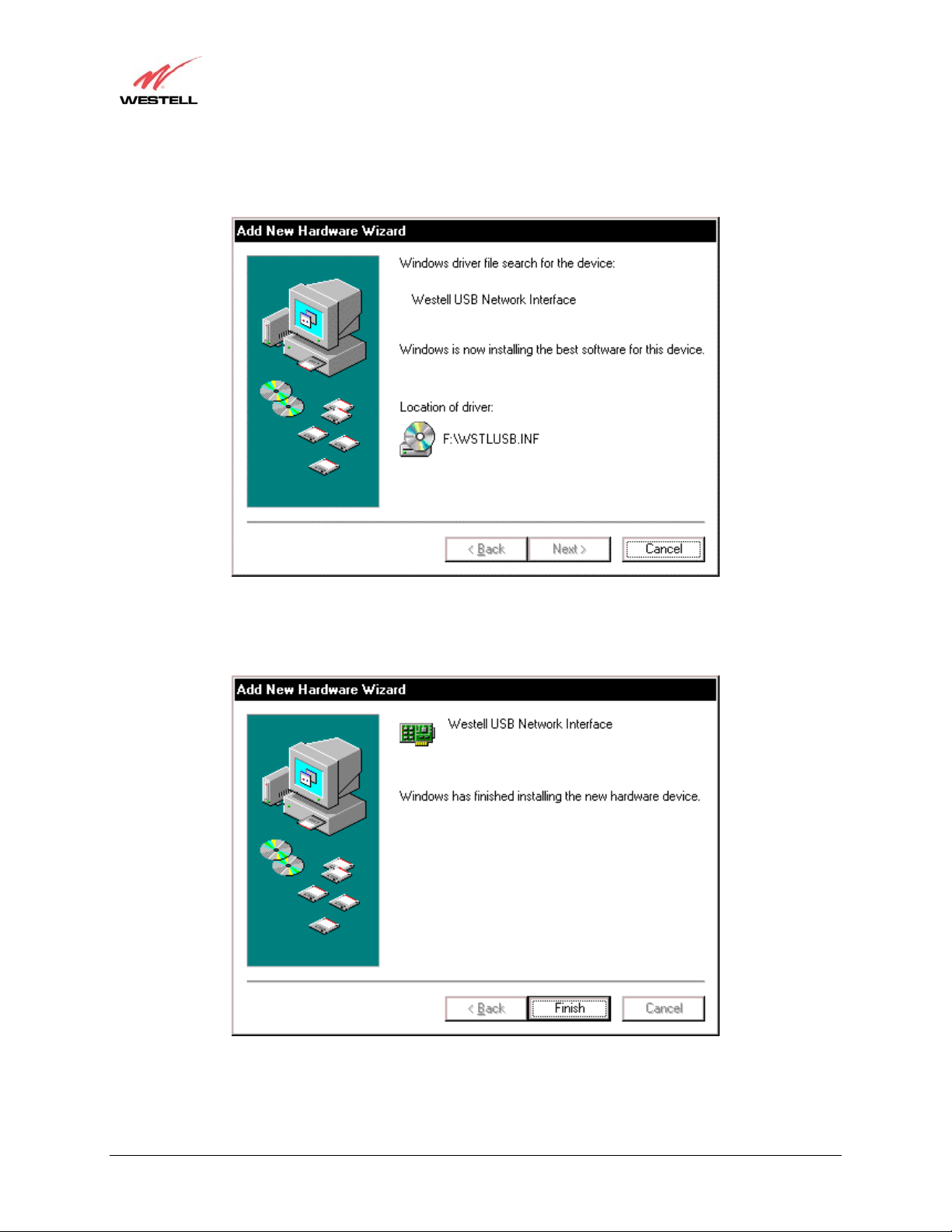
5. Windows 98 SE: Windows will display the location of the driver. See Figure 8. Click Next to continu e .
Note: The drive “letter” may vary.
Figure 8. Windows 98 SE
6. Windows 98 SE: Remove the Westell CD from the CD-ROM Drive. Next, insert the Windows operating
system CD into the CD-ROM Drive. See Figure 9. Click OK to continue.
Figure 9. Windows 98 SE
7. Windows 98 SE: The system will begin copying files (Figure 10).
Figure 10. Windows 98 SE
030-300233 Rev. A 18 May 2006
Page 19
User Guide
Westell (Models 6000, 6100, 6110)
8. Windows 98 SE: Figure 11 may pop up, depending on how Windows 98 was installed on the computer. The
installation of the Westell modem requires files that are supplied by Microsoft for Windows 98. If Figure 13
pops up, insert the Windows 98 Operating System CD into the computers CD-ROM drive, wait a moment for
the CD to be recognized by the system, and then click OK. The system should find the required files on the
Windows 98 CD and automatically complete the installation.
Figure 11. Windows 98 SE
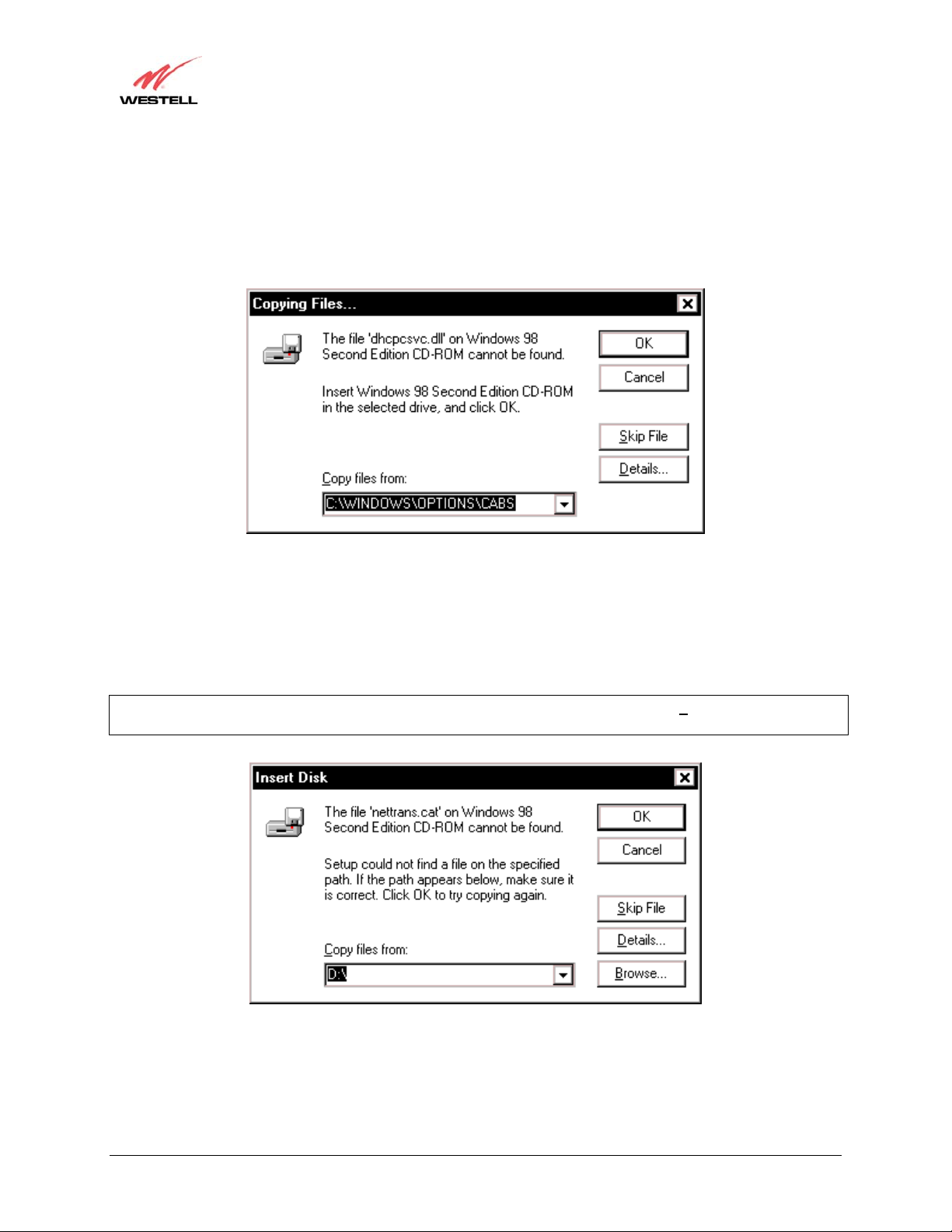
If the Operating System CD is not available, or if Figure 11 pops up again, you will have to manually specify the
location of the files. The required files may be stored on your hard drive. A common location for these files is
"C:\Windows\Options\Cabs." Try specifying this path or the path to your CD-ROM drive (usually "D:\") by clicking
the Browse… button in the Insert Disk screen. When you have specified the correct path, click OK. The system
will begin copying the files. See Figure 14.
NOTE: It is very important that the Windows 98 files be installed. Do not click Cancel or S
kip File in the dialogs,
doing so will result in an improper installation and the modem will not function co rrectly.
Figure 12. Windows 98 SE
030-300233 Rev. A 19 May 2006
Page 20
User Guide
Westell (Models 6000, 6100, 6110)
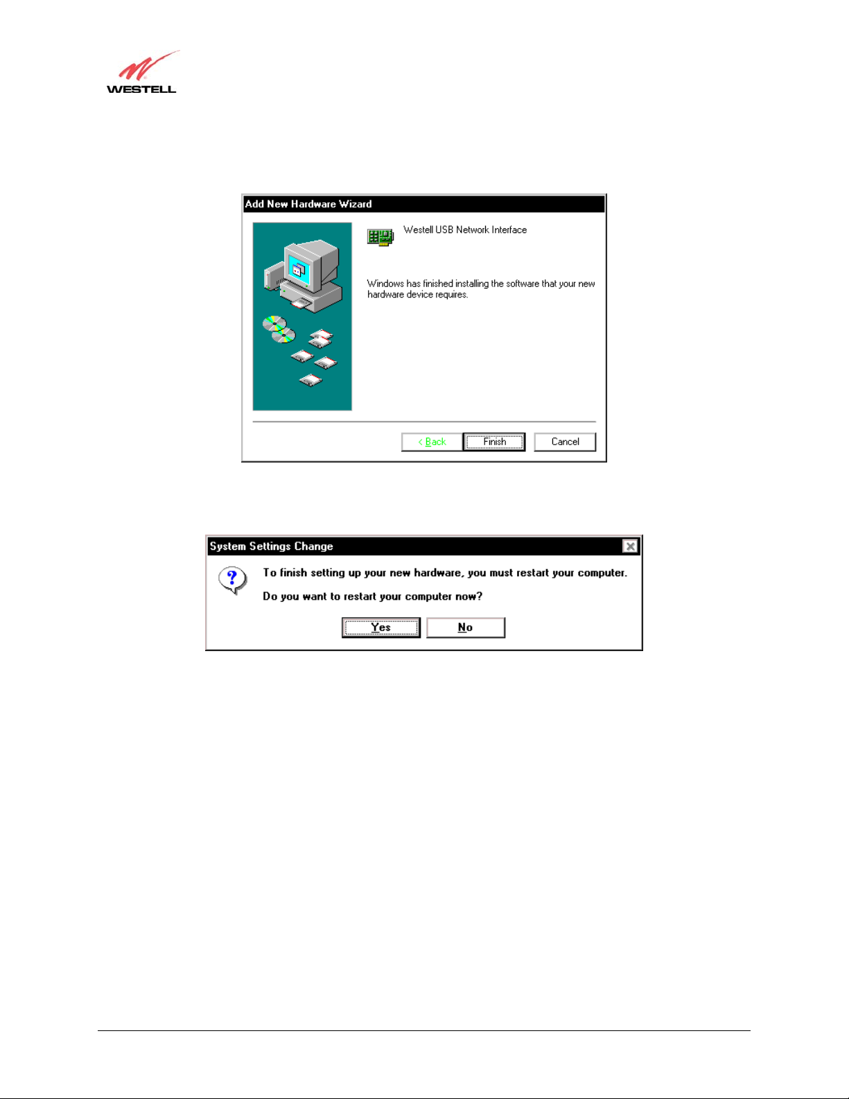
9. Windows 98 SE: The window below confirms that the PC has finished loading the drivers (Figure 13). Click
Finish.
Figure 13. Windows 98 SE
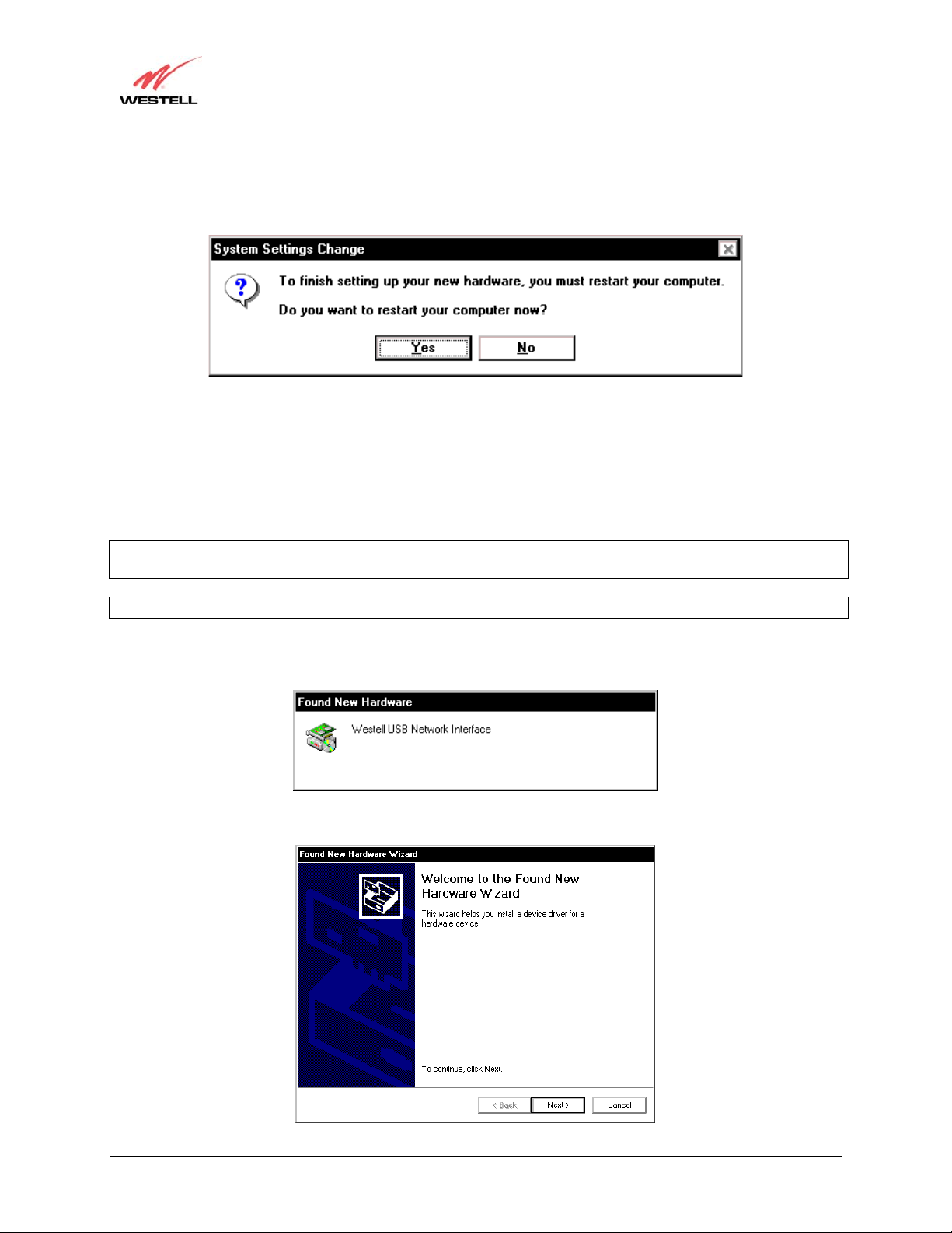
10. Windows 98 SE: Click Yes to restart your computer. See Figure 14.
Figure 14. Windows 98 SE
Congratulations! You have completed the software installation for the USB drivers. Please return to section 5,
“Installing the Hardware,” to complete the installation instructions.
030-300233 Rev. A 20 May 2006
Page 21
User Guide
Westell (Models 6000, 6100, 6110)
6.3 Installing the USB Drivers for Windows ME
IMPORTANT: Confirm that the CD-ROM provided with the modem kit is inserted in the appropriate drive before
continuing this installation.
NOTE: The actual information displayed in the USB screens may vary according to product.
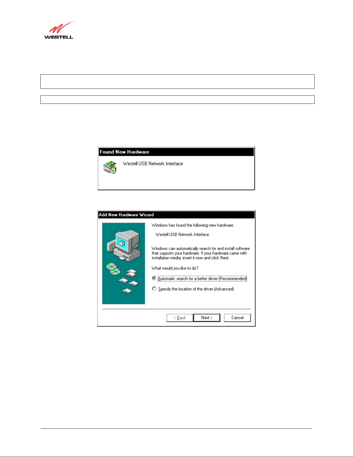
1. Windows ME: After you have connected the Modem to your PC, the Found New Hardware window appears
(Figure 15). In a few moments, the Add New Hardware Wizard window appears (Figure 16). Click the option
button Automatic search for a better driver (Recommended). Click Next to continue.
Figure 15. Windows ME
Figure 16. Windows ME
030-300233 Rev. A 21 May 2006
Page 22
User Guide
Westell (Models 6000, 6100, 6110)
2. Windows ME: Windows will display the location of the driver. See Figure 17. Click Next to continue.
Figure 17. Windows ME
3. Windows ME: The window below confirms that the PC has finished loading the drivers. See Figure 19. Click
Finish.
Figure 18. Windows ME
030-300233 Rev. A 22 May 2006
Page 23
User Guide
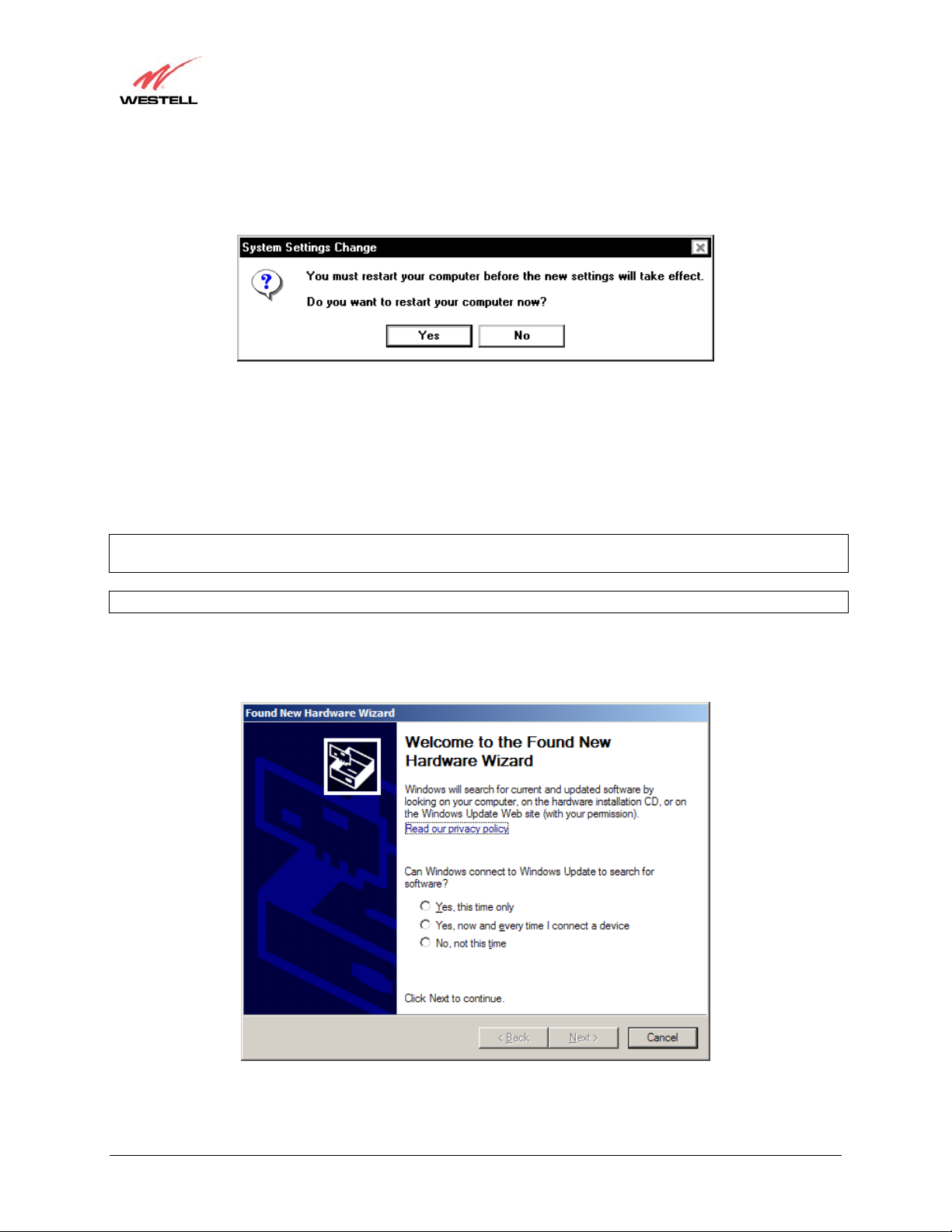
4. Windows ME: When the System Settings Change screen appears, the USB drivers are installed properly. See
Figure 19. Click Yes.
Congratulations! You have completed the software installation for the USB drivers. Please return to section 5,
“Installing the Hardware,” to complete the installation instructions.
Westell (Models 6000, 6100, 6110)
Figure 19. Windows ME
6.4 Installing the USB Driver for Windows 2000
IMPORTANT: Confirm that the CD-ROM provided with the modem kit is inserted in the appropriate drive before
continuing this installation.
NOTE: The actual information displayed in the USB screens may vary according to product.
1. Windows 2000: After you have connected the Modem to your PC, the Found New Hardware window appears
(Figure 20). In a few moments, the Found New Hardware Wizard window appears (Figure 21). Click Next.
Figure 20. Windows 2000
Figure 21. Windows 2000
030-300233 Rev. A 23 May 2006
Page 24
User Guide
Westell (Models 6000, 6100, 6110)
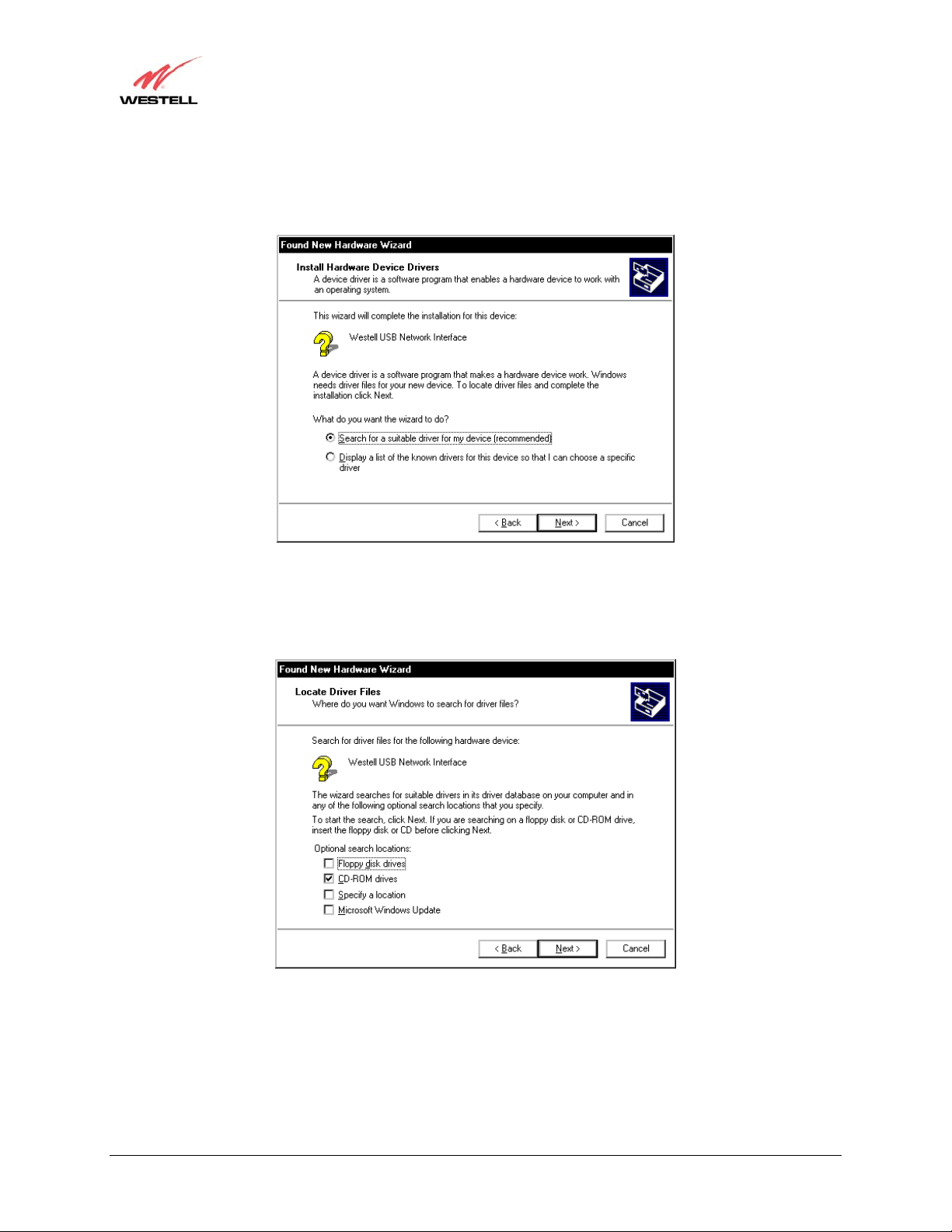
2. Windows 2000: The Install Hardware Device Drivers window appears. Select Search for a suitable driver
for my device (recommended) See Figure 22. Click Next.
Figure 22. Windows 2000
3. Windows 2000: The Locate Driver Files window appears. Select the CD-ROM drives option. See Figure 23.
Click Next.
Figure 23. Windows 2000
030-300233 Rev. A 24 May 2006
Page 25
User Guide
Westell (Models 6000, 6100, 6110)
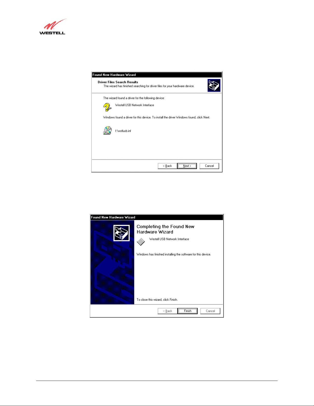
4. Windows 2000: The Driver Files Search Results window appears (Figure 24). Click Next to continue.
Note: The drive “letter” may vary.
Figure 24. Windows 2000
5. Windows 2000: The window below confirms that the PC has finished loading the drivers (Figure 25). Click
Finish.
Figure 25. Windows 2000
030-300233 Rev. A 25 May 2006
Page 26
User Guide
6. Windows 2000: When the System Settings Change screen appears, the USB drivers are installed properly. See
Figure 26. Click Yes.
Congratulations! You have completed the software installation for the USB drivers. Please return to section 5,
“Installing the Hardware,” to complete the installation instructions.
Westell (Models 6000, 6100, 6110)
Figure 26. Windows 2000
6.5 Installing the USB Driver for Windows XP
IMPORTANT: Confirm that the CD-ROM provided with the modem kit is inserted in the appropriate drive before
continuing this installation.
NOTE: The actual information displayed in the USB screens may vary according to product.
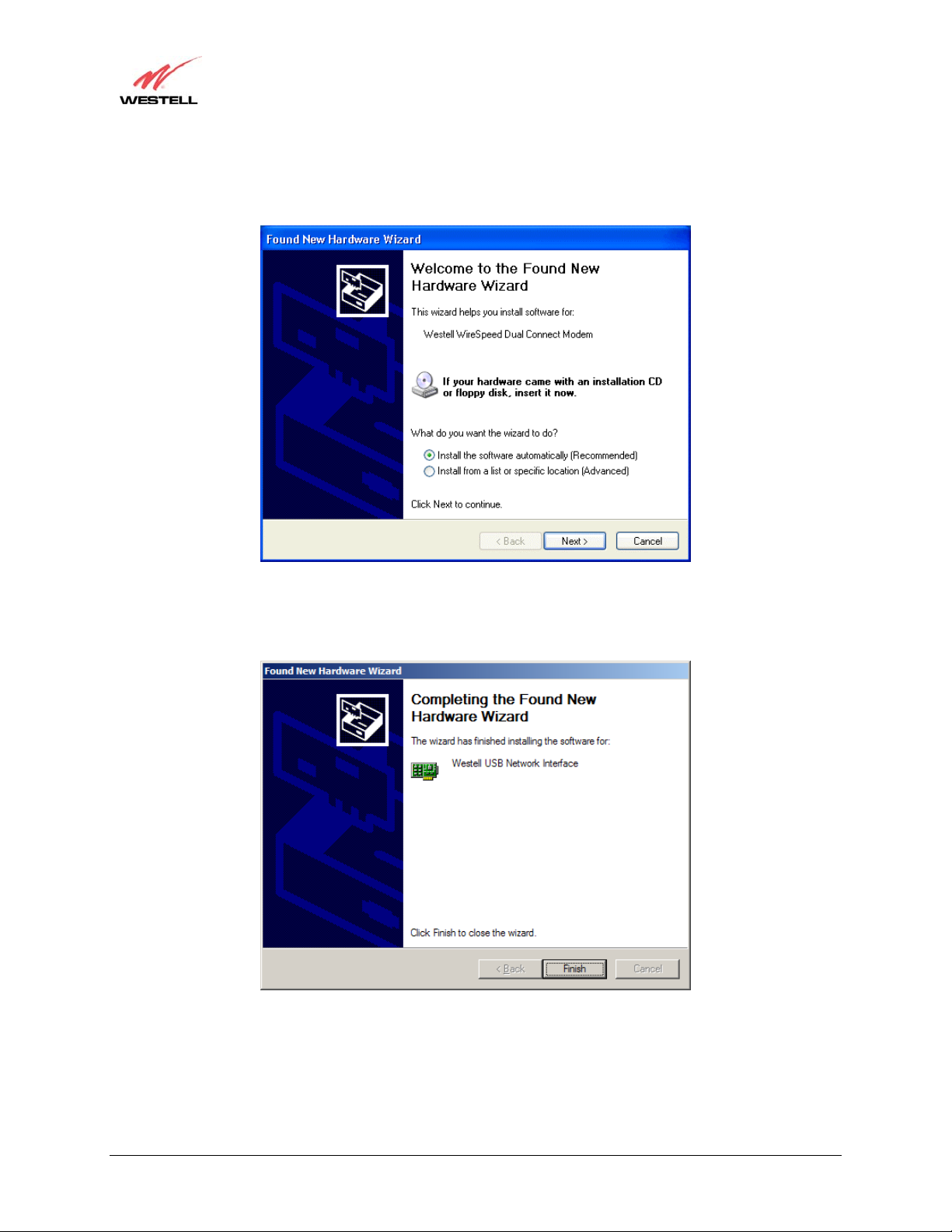
1. Windows XP: After you have connected the Modem to your PC, the Found New Hardware Wizard window
will open. See Figure 28. Select the desired option b utton, and then click Next to continue.
Figure 27. Windows XP
030-300233 Rev. A 26 May 2006
Page 27
User Guide
Westell (Models 6000, 6100, 6110)
2. Windows XP: Next, select option button Install the software automatically (Recommended). See Figure 28.
Click Next to continue.
Figure 28. Windows XP
3. Windows XP: The window below confirms that the PC has finished loading the drivers (Figure 29). Click
Finish.
Figure 29. Windows XP
Congratulations! You have completed the software installation for the USB drivers. Please return to section 5,
“Installing the Hardware,” to complete the installation instructions.
030-300233 Rev. A 27 May 2006
Page 28
User Guide
Westell (Models 6000, 6100, 6110)
7. CONFIGURING YOUR ROUTER FOR INTERNET CONNECTION
(MODEL 6100)
To browse the Internet using your Westell Router, you must set up your account profile, confirm your DSL sync, and
establish a PPP session with your Internet service provider (ISP).
7.1 Setting Up an Account Profile
Your account profile is used to identify you to your ISP.
IMPORTANT: Before you set up your account profile, obtain your Account ID and Account Password from your
ISP. You will use this information when you set up your account parameters.
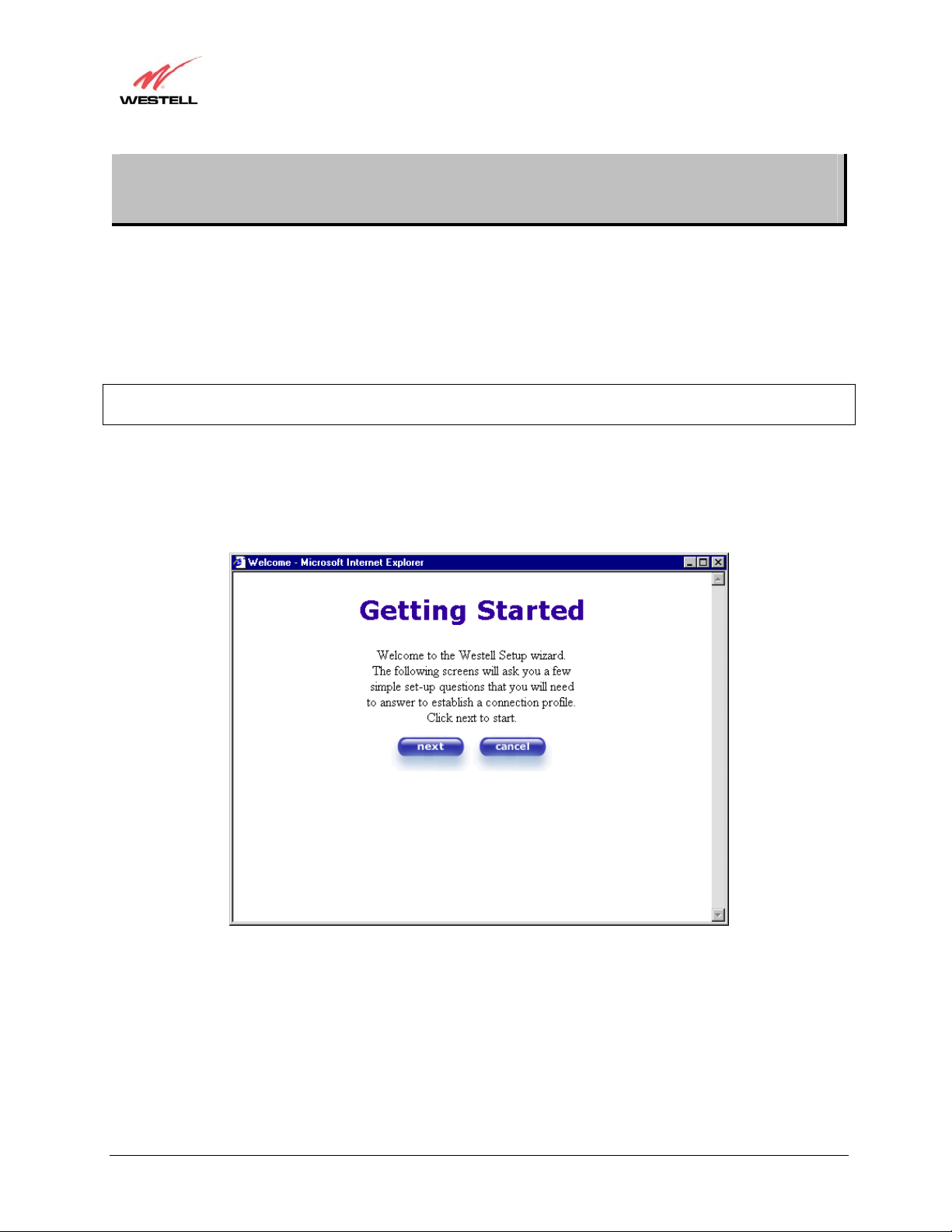
To begin your account set up, start your web browser and type the following IP address in the browser’s address bar:
http://192.168.1.1
Next, press Enter on your keyboard. The Getting Started screen will appear. Click next to continue.
030-300233 Rev. A 28 May 2006
Page 29
p
User Guide
Westell (Models 6000, 6100, 6110)
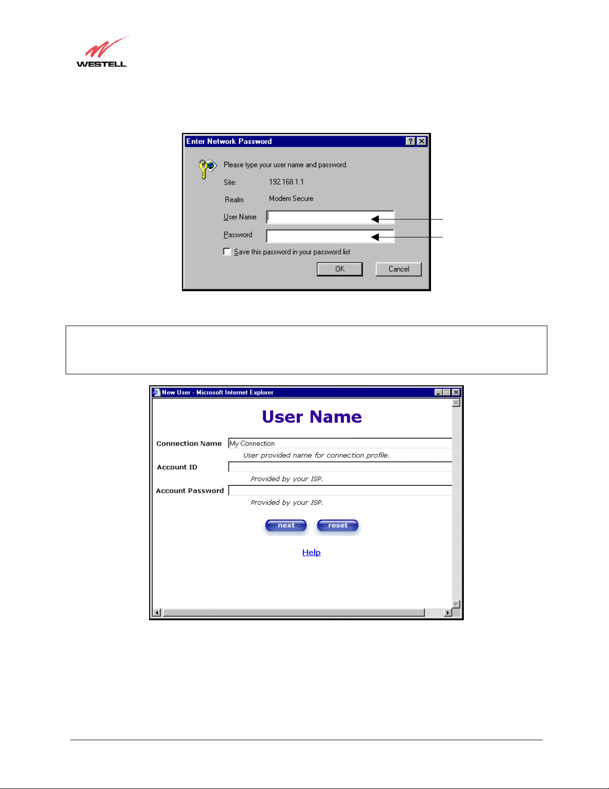
If you clicked next, the following screen will appear. Type the default username (which is admin) and the default
password (which is password) in the fields provided. Then click OK to continue.
admin
assword
If you clicked next, the following screen will be displayed. This screen will allow you to set up your account profile.
NOTE: Before you set up your account profile, you must obtain your Account ID, Account Password, and
VPI/VCI values from your Internet service provider. You will use this information when you set up your account
parameters. If you are at a screen and need help, click the Help button to learn more about the screen, or see
Appendix A-Help for additional information on the help messages.
030-300233 Rev. A 29 May 2006
Page 30
User Guide
Westell (Models 6000, 6100, 6110)
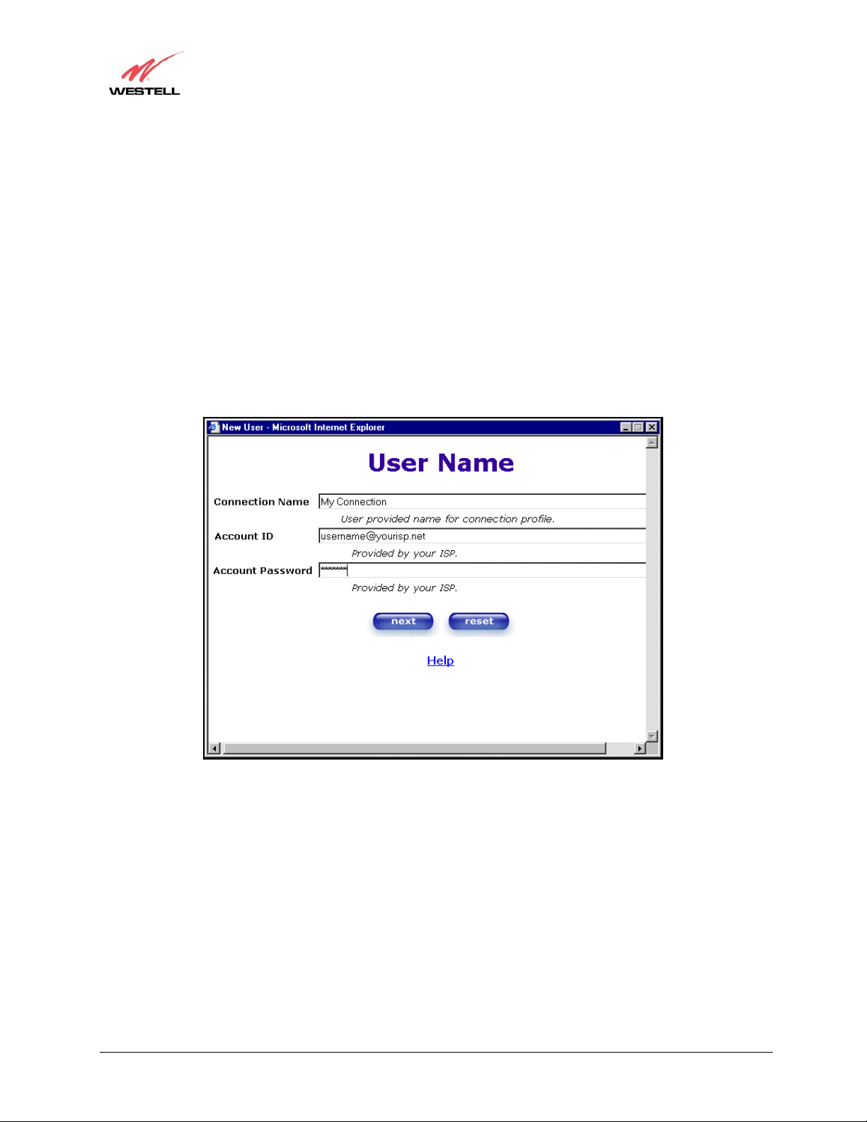
Type in your account parameters. (Account parameters are required before connecting to the Internet.)
Account Parameters include:
● Connection Name-the Connection Name is a word or phrase that you use to identify your account.
(You may enter up 64 characters in this field.)
● Account ID-the Account ID is provided by your Internet Service Provider.
(You may enter up 255 characters in this field.)
● Account Password-the Account Password is provided by your Internet Service Provider.
(You may enter up 255 characters in this field.)
When you enter your account parameters at the User Name screen, they will be displayed, as shown in the screen
below. (Note: The password field will be masked with asterisks for security purposes.) After you have entered your
account parameters, click next to allow your parameters to take effect. Click reset if you do not want the account
parameters that you entered to take effect or if you want to re-enter the parameters.
030-300233 Rev. A 30 May 2006
Page 31

N
N
User Guide
Westell (Models 6000, 6100, 6110)
Enter the VPI and VCI values that you obtained from your Internet service provider. Click next to continue.
OTE: Depending on your Internet Service
Provider, the VPI/VCI screen may come
pre-configured and it will be displayed here.
In this case, you should not change any
values in this screen. Click next to go to the
PROTOCOL screen.
Select the Protocol type that you obtained from your Internet Service Provider. Click next to continue.
OTE: Depending on your Internet Service
Provider, the PROTOCOL screen may
come pre-configured and it will be displayed
here. In this case, you will need to click next
to go to the SET-UP COMPLETE screen.
When the SET-UP COMPLETE screen appears, you have successfully completed your Account Profile setup.
Click done.
030-300233 Rev. A 31 May 2006
Page 32

User Guide
Westell (Models 6000, 6100, 6110)
7.2 Establishing a PPP Session
View the Connection Rate at the Connection Overview section in the following Home page. If this status reads No
DSL Connection, check the DSL physical connection, which is explained in section 5 (INSTALLING THE
HARDWARE).
NOTE: If no DSL sync is established, the connect button will not be displayed. To determine if the DSL sync is
established, check the Modem’s DSL LED. If the DSL LED is not solid green, you do not have a DSL link
established. Contact your ISP for details.
The screen below shows the connection rate with values that indicate a successful SYNC has been established. The
connection rate values represent the transmission speed of your DSL line. (The Modem may take time to report the
values.) Click the connect button to establish a PPP session.
NOTE: When viewing the screens, please note that the actual values might differ from the values displayed in this
User Guide.
If you clicked connect, the following screen will appear briefly. The PPP Status in the Connection Overview screen
allows you to view the state of your ISP connection. When the PPP Status displays Connecting…, this means that
you are establishing a PPP session.
NOTE: The Modem will handle transmission rates up to 8 Mbps. Your actual DSL rates may vary depending on
your Internet service provider.
030-300233 Rev. A 32 May 2006
Page 33

User Guide
Westell (Models 6000, 6100, 6110)
Once a PPP session has been established, the PPP Status will display UP. Congratulations! You may now surf the
Internet.
030-300233 Rev. A 33 May 2006
Page 34

User Guide
For example, if you want to visit Westell’s home page, type http://www.westell.com in your browser’s address bar,
and then press Enter on your keyboard.
Westell (Models 6000, 6100, 6110)
7.3 Disconnecting a PPP Session
If you are ready to disconnect from your Internet service provider, click the Disconnect button in the Connection
Overview screen. The following pop-up screen will appear. Click on OK to disconnect the PPP session.
The screen below will appear briefly. When the PPP Status displays Disconnecting…, this means that you are
disconnecting from your PPP session.
030-300233 Rev. A 34 May 2006
Page 35

User Guide
Westell (Models 6000, 6100, 6110)
If you clicked the Disconnect button in the preceding Connection Overview screen, the PPP Status should display
DOWN. This means that you no longer have an ISP connection. In this event, your Modem will maintain its DSL
connection. If you want to remove the DSL connection, power down the Router via the power switch on the rear of
the Modem. Refer to Appendix D-Exiting the Router when you are ready to exit the Modem.
When you are ready to establish a PPP session, click the connect button. (If you have previously turned off your
modem, first turn on the modem and then log on to your account profile to establish a PPP session.)
NOTE: When you are ready to exit the modem’s interface, click the X (close) in the upper-right corner of the
window. Closing the window will not affect your PPP Status (your PPP session will not be disconnected). You must
click the disconnect button to disconnect your PPP session. When you are ready to restore this interface, launch your
Internet browser and type http://192.168.1.1 in the browser’s address bar, and press Enter on your keyboard.
030-300233 Rev. A 35 May 2006
Page 36

User Guide
Westell (Models 6000, 6100, 6110)
8. SETTING UP MACINTOSH OS X (MODEL 6100)
This section provides instructions on how to use Macintosh OS X (Operating System 10) with your Westell Modem.
Follow the instructions in this section to create a new network configuration for Macintosh OS X.
IMPORTANT: The USB installation will not function for Macintosh Computers. Macintosh computers must use
the Modem’s Ethernet installation. Refer to section 5.4.1 for installation instructions via Ethernet.
8.1 Open the System Preference Screen
After you have connected the Westell Modem to the Ethernet port of your Macintosh, the screen below will appear.
Click on the “Apple” icon in the upper right corner of the screen and select System Preferences.
8.2 Choose the Network Preferences
After selecting System Preferences…, from the previous screen, the System Preferences screen will be displayed.
From the System Preferences screen, click the Network icon.
030-300233 Rev. A 36 May 2006
Page 37

User Guide
Westell (Models 6000, 6100, 6110)
8.3 Create a New Location
After selecting the Network icon at the System Preferences screen, the Network screen will be displayed. Select
New Location from the Location field.
8.4 Name the New Location
After selecting New Location from the Network screen, the following screen will be displayed. In the field labeled
Name your new location:, change the text from “Untitled” to “Westell.” Click on OK.
8.5 Select the Ethernet Configuration
After clicking on OK in the previous step, the Network screen will be displayed. The Network screen shows the
settings for the newly created location. From the Configure field in the Network screen, select Built-in Ethernet.
Click on Save.
NOTE: Default settings for the Built-in Ethernet configuration are sufficient to operate the Modem.
030-300233 Rev. A 37 May 2006
Page 38

User Guide
Westell (Models 6000, 6100, 6110)
8.6 Check the IP Connection
To verify that the computer is communicating with the Modem, follow the instructions below.
1. Go to the “Apple” icon in the upper right corner of the screen and select System Preferences.
2. From the System Preferences screen, click the Network icon. The Network screen will be displayed.
3. From the Configure field in the Network screen, select Built-in Ethernet.
4. View the IP address field. An IP address that begins with 192.168.1 should be displayed.
NOTE: The DHCP server provides this IP address. If this IP address is not displayed, check the Modem’s wiring
connection to the PC. If necessary, refer to section 5 for installation instruction s .
030-300233 Rev. A 38 May 2006
Page 39

User Guide
Westell (Models 6000, 6100, 6110)
8.7 Create a User Account
In the address window of your Internet Explorer web browser, type http://dslrouter/ or type http://192.168.1.1/ and
press enter on your keyboard.
The Getting Started screen will be displayed. You may now begin your Account Setup. Refer to section 7 of this
user guide to configure your modem for Internet connection.
030-300233 Rev. A 39 May 2006
Page 40

User Guide
Westell (Models 6000, 6100, 6110)
9. SETTING UP ADVANCED CONFIGURATION (MODEL 6100)
Advanced Configuration instructions for Model 6100 are explained in Sections 10 through 16. These instructions
apply to Model 6100 only. If you are an advanced user, follow the instructions provided in sections 10 through 16 to
configure the advanced settings.
Model 6100 allows you to make changes to the advanced features such as account profiles, routing configurations,
and firewall settings. The following sections explain each feature and how to change the settings. The main menu
displayed at the top of each page allows you to navigate to the various configuration screens. Whenever you change
the configurable settings of Model 6100, you must click save in the screen to allow the changes to take effect. If you
are at a screen and need help, click the Help button to learn more about that screen.
IMPORTANT:
1. The following sections assume that you have active DSL and Internet service.
2. Hereafter, Model 6100 will be referred to as “Router.”
10. HOME
10.1 Setting Up Advanced Configuration
As you navigate through the various screens of your Router, the name of the active page that you have selected will
appear in the upper-left corner of the screen, as shown below. Please note that the actual values reported by your
Router may differ from the values displayed in this user guide.
If you have set up your account profile and established your PPP session with your ISP, as discussed in section 7,
“Configuring Your Router for Internet Connection,” the following screen will be displayed if you click Home in the
main menu.
030-300233 Rev. A 40 May 2006
Page 41

User Guide
Connection Overview Displays your DSL connection rate.
Connection Name This Connection Name is from the connection profile that you established in section 7.
PPP Status UP = PPP session established
Connect/Disconnect Connect—click this button to establish a PPP session with your ISP.
Profile Editor This allows you to make changes to the profile that you created in section 7.
Westell (Models 6000, 6100, 6110)
DOWN = No PPP session established.
Disconnect—click this button to disconnect your PPP session.
10.2 Adding Account Profiles
To add an account profile, click the Profile Editor button in your Home screen, the Advanced Home screen will
appear, as shown below. Click the new connection button in the Advanced Home screen. The New Connection
screen will appear. Enter the profile information (Account ID and Account Password that you entered in section 7.1)
and then click new.
NOTE: You may store up to eight unique user profiles in your Router. Details on the New Connection screen are
located at the end of this section.
If you clicked new, the following pop-up screen will appear. Click OK in the pop-up screen to save your new
connection. If you do not want to add a new connection profile, click Cancel in the pop-up screen.
030-300233 Rev. A 41 May 2006
Page 42

User Guide
If you clicked OK in the pop-up screen, the following screen will be displayed. This screen displays the new profile
“My New Connection.”
IMPORTANT: Although you have added a new profile, your Internet connection will be available only for the
default profile, which you have set up in section 7.1. To establish a PPP session and browse the Internet using the
new profile, you must first configure the new profile as your default account profile. To do this, click the radio button
adjacent to the connection name that you want to use as your default connection profile. Next, click OK when asked
“Do you wish to change the Default Connection Profile?”
Westell (Models 6000, 6100, 6110)
10.3 Edit Account Profiles
To edit an account profile, click the edit button adjacent to the connection name that you want to edit. The “Edit My
Connection” screen will appear.
NOTE: If you have created multiple account profiles, first select the option button for the active account profile.
Next, enter the desired values in the Edit “My Connection” screen and click save. Next, click OK in the pop-up
screen to save the changes. If you want to delete the profile click delete in the “Edit My Connection” screen.
030-300233 Rev. A 42 May 2006
Page 43

User Guide
Westell (Models 6000, 6100, 6110)
Edit My Connection
Connection Name This field allows you to enter a new connection name of your choice (up to 64
characters).
Account ID Use the same account ID that you used in section 7 if you are connecting to the
same Service Provider. If you have multiple Service Providers, you can enter this
information at this time.
Account Password Use the same account password that you used in section 7 if you are connecting
to the same Service Provider. If you have multiple Service Providers, you can
enter this information at this time.
Service Profile Westell recommends that you use the Default parameter.
Manual Factory default = MANUAL
Selecting this feature allows you to manually establish your PPP session.
On Demand Selecting this feature allows the Router to automatically re-establish your PPP
session upon demand.
Always On Selecting this feature allows the Router to establish an “always-on” PPP session
if it goes down.
Save Password Selecting this feature allows you to save the password for your new connection
profile in your Router so that you will not have to re-enter it in case of a re-boot.
030-300233 Rev. A 43 May 2006
Page 44

User Guide
Westell (Models 6000, 6100, 6110)
11. STATUS
11.1 Connection Summary
The following screen will be displayed if you select Status > Connection Summary from the main menu.
NOTE: The actual information displayed in this screen may vary.
DSL Connection Information
Connection Rate This field will let you know if you have a DSL Sync (UP/DOWN) and the DSL rate
at which you are connected.
Connection Status This field will display how much information was received (IN) or sent (OUT) in
packets.
IP Network Address PPP = An IP address identifies your device on the Internet
Primary DNS = Provided by your Service Provider
Secondary DNS = Provided by your Service Provider
Ethernet Status This field will display your Ethernet information that was received (IN) or sent
(OUT) in packets on your Ethernet port.
ATM Network Address This field will display your VPI and VCI values, which are provided by your Intern et
Service Provider.
Firewall Status This field will display you r firewall traffic in packets.
Passed: Monitors information traffic that was successfully received (IN) or
transmitted (OUT) in packets.
030-300233 Rev. A 44 May 2006
Page 45

User Guide
Connection Name This is from the connection profile that you established in section 7.
Connection Duration This field will display how long your PPP session has been connected.
Status This field will display the status of your PPP session.
Number of Reconnects This field will display the number of attempts that were made to establish a PPP
Westell (Models 6000, 6100, 6110)
Dropped: Monitors information traffic that was not successfully received (IN) or
transmitted (OUT) due to your firewall settings.
PPP Connection Information
UP=Connected
DOWN=Disconnected
session.
11.2 About
The following settings will be displayed if you select Status > About from the main menu.
Model Number Router manufacturer’s model number.
Serial Number Router manufacturer’s serial number.
MAC Address MAC address of this device.
Software Version Version of Application Software.
Software Model Router application type.
Description Product description.
Boot Loader Version of boot loader software
030-300233 Rev. A 45 May 2006
Page 46

User Guide
Westell (Models 6000, 6100, 6110)
12. CONFIGURATION
12.1 VC Configuration
The following settings will be displayed if you select Configuration > VC Configuration from the main menu.
If you change any settings in this screen, click save filter settings to save the changes.
NOTE: The actual information displayed in this screen may vary, depending on the network connection established.
NOTE: If you experience any problems, please reset your Router via the external hardware reset button or via the
procedure defined in section 14, “Maintenance” in Backup/Restore.
Status Allows you to enable or disable your VC (Virtual Connection)
VPI Displays the VPI (Virtual Path Indicator) value for a particular VC, which is
defined by your Service Provider.
VCI Displays the VCI (Virtual Channel Indicator) value for a particular VC,
which is defined by your Service Provider.
Protocol
NOTE: The configuration
specified by your Service
Provider will determine which
Protocols are available to you.
Bridge Broadcast Factory Default = CHECKED
030-300233 Rev. A 46 May 2006
Displays the Protocol for each VC, which is specified by your Service
Provider.
Possible Responses:
PPPoA = Point to Point Protocol over ATM (Asynchronous Transfer Mode)
PPPoE = Point to Point Protocol over Ethernet
Bridge = Bridge Protocol
Classical IPoA = Internet Protocol over ATM (Asynchronous Transfer
Mode). This is an ATM encapsulation of the IP protocol.
Page 47

User Guide
When this setting is CHECKED, the Router will allow Broadcast IP packets
Bridge Multicast Factory Default = CHECKED
Spanning Tree Protocol Factory Default = DISABLED
Westell (Models 6000, 6100, 6110)
to/from the WAN.
When this setting is NOT CHECKED, the router will block Broadcast IP
packets to/from the WAN.
This setting is only valid if one of the Virtual Channels is configured for
Bridge mode.
When this setting is CHECKED, the Router will allow Multicast IP packets
to/from the WAN.
When this setting is NOT CHECKED, the Router will block Multicast IP
packets to/from the WAN.
This setting is only valid if one of the Virtual Channels is configured for
Bridge mode.
Spanning Tree Protocol is a link management protocol that provides path
redundancy while preventing undesirable loops in the network. For Ethernet
network to function properly, only one active path can exist between two
stations.
When ENABLED, two bridges are used to interconnect the same two
computer network segments. Spanning Tree Protocol will allow the bridges to
exchange information so that only one of them will handle a given message
that is being sent between two computers within the network.
12.2 Editing the VC Configuration
To edit the VC configuration of your Router, click the edit button adjacent to any of the “Enabled” protocols
displayed in the VC Configuration screen.
NOTE: The protocol must display “Enable” to allow edits to its VC configuration.
030-300233 Rev. A 47 May 2006
Page 48

User Guide
Westell (Models 6000, 6100, 6110)
If you clicked edit, the following VC 1 Configuration screen will be displayed. The VC 1 Configuration screen
allows you to edit your virtual connection (VC). A virtual connection identifies a connection through the service
provider’s ATM network to your ISP. Unlike physical hardware connections, virtual connections are defined by data.
NOTE: If you experience any problems, please reset your Router via the external hardware reset button or via the
procedure defined under the Maintenance menu.
If you change any settings in the VC 1 Configuration screen, click the Set VC button to save the settings.
VC 1 Configuration
VPI This setting allows you to change your VPI (Virtual Path Indicator) value for a
particular VC, which is defined by your Service Provider.
VCI This setting allows you to change your VCI (Virtual Channel Indicator) value for a
particular VC, which is defined by your Service Provider.
PCR Factory Default = 100%
Peak Cell Rate (PCR)-The maximum rate at which cells can be transmitted across a
virtual circuit, specified in cells per second and defined by the interval between the
transmission of the last bit of one cell and the first bit of the next.
This value is a percentage of the current data rate.
100 allows this VC to use 100% of the available bandwidth.
80 allows this VC to use 80% of the available bandwidth.
QoS Quality of Service, which is determined by your Service Provider.
030-300233 Rev. A 48 May 2006
Page 49

User Guide
Westell (Models 6000, 6100, 6110)
Possible Responses:
CBR = Constant Bit Rate
UBR = Unspecified Bit Rate
VBR = Variable Bit Rate
Protocol The Protocol for each VC, which is specified by your Service Provider.
Possible Responses:
PPPoA = Point to Point Protocol over ATM (Asynchronous Transfer Mode)
PPPoE = Point to Point Protocol over Ethernet
Bridge = Bridge Protocol
Classical IPoA = Internet Protocol over ATM (Asynchronous Transfer Mode). This
is an ATM encapsulation of the IP protocol.
Status The protocol status.
VC x PPPoE Settings
IP Address Displays the IP network address that your modem is on.
Gateway Displays the router IP Gateway address
DNS Primary Provided by your Service Provider
DNS Secondary Provided by your Service Provider
MRU Negotiation Factory Default = DISABLED
If ENABLED, the Maximum Received Unit (MRU) would enforce MRU
negotiations. (NOTE: enable this option only at your Internet Service Provider’s
request.)
LCP Echo Disable Factory Default = Enable
If checked, this option will disable the modem LCP Echo transmissions.
LCP Echo Failures Indicates number of continuous LCP echo non-responses received before the PPP
session is terminated.
LCP Echo Retry Duration Indicates the interval between LCP Echo transmissions with responses.
LCP Echo Retry Duration Indicates the interval between LCP. Echo after no response.
Tunneling Factory Default = ENABLE
If ENABLED, this option allows PPP traffic to be bridged to the WAN. This feature
allows you to use a PPPoE shim on the host computer to connect to the Internet
Service Provider, by bypassing the Router’s capability to do this.
NOTE: The values for IP Address, Gateway, DNS Primary, and DNS Secondary are all “Override of the value
obtained from the PPP connection,” They default to “0.0.0.0,” in which case the override is ignored. Westell
recommends that you do not change the values unless your Internet Service Provider instructs you to change them.
If you made any changes and clicked the set VC button in the VC 1 Configuration screen, the following pop-up
screen will appear. Click OK in the pop-up screen. If you click cancel, the new VC settings will not be saved.
If you clicked OK in the preceding pop-up screen, the following pop-up screen will appear. Click OK to continue.
030-300233 Rev. A 49 May 2006
Page 50

User Guide
If you clicked OK in the preceding pop-up screen, the following screen will appear. The Router will be reset and the
new configuration will take effect. After the Router has been reset, confirm that you have a DSL sync and that your
PPP session displays UP. (If necessary, click the connect button in Home screen to establish a PPP session.)
Westell (Models 6000, 6100, 6110)
12.2.1 Configuring the Router’s Protocol for PPPoA Mode
To configure the Router’s protocol settings for PPPoA mode, select PPPoA from the Protocol drop-down menu. The
following screen will appear. Next, click the set VC button to save the settings.
030-300233 Rev. A 50 May 2006
Page 51

User Guide
If you clicked the set VC button, the following pop-up screen will appear. Click OK in the pop-up screen, and then
follow the instructions to reset the Router, as explained in section 12.2. If you click Cancel, the new settings will not
take effect.
Westell (Models 6000, 6100, 6110)
12.2.2 Configuring the Router’s Protocol for PPPoE Mode
To configure the Router’s protocol settings for PPPoE mode, select PPPoE from the Protocol drop-down menu. The
following screen will appear. Next, click the set VC button to save the settings.
030-300233 Rev. A 51 May 2006
Page 52

User Guide
If you clicked the set VC button, the following pop-up screen will appear. Click OK in the pop-up screen, and then
follow the instructions to reset the Router, as explained in section 12.2. If you click Cancel, the new settings will not
take effect.
Westell (Models 6000, 6100, 6110)
12.2.3 Configuring the Router’s Protocol for Bridge Mode
To configure the Router’s protocol settings for Bridge mode, select Bridge from the Protocol drop-down menu. The
following screen will appear.
VC 1 Configuration
VPI This setting allows you to change your VPI (Virtual Path Indicator) value for a particular VC,
which is defined by your Service Provider.
VCI This setting allows you to change your VCI (Virtual Channel Indicator) value for a particular VC,
which is defined by your Service Provider.
PCR Factory Default = 100%
Peak Cell Rate (PCR)-The maximum rate at which cells can be transmitted across a virtual circuit,
specified in cells per second and defined by the interval between the transmission of the last bit of
one cell and the first bit of the next.
This value is a percentage of the current data rate.
100 allows this VC to use 100% of the available bandwidth.
030-300233 Rev. A 52 May 2006
Page 53

User Guide
Westell (Models 6000, 6100, 6110)
80 allows this VC to use 80% of the available bandwidth.
QoS Quality of Service, which is determined by your Service Provider.
Possible Responses:
CBR = Constant Bit Rate
UBR = Unspecified Bit Rate
VBR = Variable Bit Rate
Protocol The Protocol for each VC, which is specified by your Service Provider.
Possible Responses:
PPPoA = Point to Point Protocol over ATM (Asynchronous Transfer Mode)
PPPoE = Point to Point Protocol over Ethernet
Bridge = Bridge Protocol
Classical IPoA = Internet Protocol over ATM (Asynchronous Transfer Mode). This is an ATM
encapsulation of the IP protocol.
Status The protocol status.
VC 1 Bridge Settings
Bridge = A bridge is a layer 2 device that connects two segments of the same LAN that use the
same protocol such as Ethernet. The modem does not have a WAN IP address in this mode. The
client PC will typically get an IP address from a DHCP server in the network or the IP address can
be assigned statically.
Routed Bridge = Routed Bridged Encapsulation (RBE) is the process by which a bridged segment
is terminated on a routed interface. Specifically, the router is routing on an IEEE 802.3 or
Ethernet header carried over RFC 1483 bridged ATM. RBE was developed to address the known
Mode
RFC1483 bridging issues, including broadcast storms and security. The modem will get a WAN
IP address through DHCP or can be assigned statically. NAT will use the global address assigned
to the modem.
Proxy Bridge = Proxy Bridge is the process in which the modem acts as a proxy ARP agent for a
local public subnet. The modem will be assigned an IP address from within that public subnet.
The modem will direct all traffic to a gateway, which is configured statically. The gateway
address must not reside within the modems assigned public subnet. All traffic will be sent via the
gateway MAC address. The LAN may also have a private NAT'ed network. NAT will use the
global address assigned to the modem.
Next, select a mode (Bridge, Routed Bridge, or Proxy Bridge) from the Mode drop-down menu, below VC 1–Bridge
Settings, and then click the set VC button to save the settings.
030-300233 Rev. A 53 May 2006
Page 54

User Guide
Westell (Models 6000, 6100, 6110)
12.2.3.1 Bridge Protocol (Bridge Mode)
If you selected Bridge from the Mode drop-down menu, the following screen will appear. Click set VC to continue.
If you clicked the set VC button, the following pop-up screen will appear. Click OK in the pop-up screen, and then
follow the instructions to reset the Router, as explained in section 12.2. If you click Cancel, the new settings will not
take effect.
030-300233 Rev. A 54 May 2006
Page 55

User Guide
Westell (Models 6000, 6100, 6110)
12.2.3.2 Bridge Protocol (Routed Bridge Mode)
If you selected Routed Bridge from the Mode drop-down menu, the following screen will appear. Click set VC.
If you clicked the set VC button, the following pop-up screen will appear. Click OK in the pop-up screen, and then
follow the instructions to reset the Router, as explained in section 12.2. If you click Cancel, the new settings will not
take effect.
030-300233 Rev. A 55 May 2006
Page 56

User Guide
Westell (Models 6000, 6100, 6110)
12.2.3.3 Bridge Protocol (Proxy Bridge Mode)
If you selected Proxy Bridge from the Mode drop-down menu, the following screen will appear. Click set VC.
If you clicked the set VC button, the following pop-up screen will appear. Click OK in the pop-up screen, and then
follow the instructions to reset the Router, as explained in section 12.2. If you click Cancel, the new settings will not
take effect.
030-300233 Rev. A 56 May 2006
Page 57

User Guide
Westell (Models 6000, 6100, 6110)
12.2.4 Configuring the Router’s Protocol for Classical IPoA Mode
To configure the Router’s protocol settings for Classical IPoA mode, select Classical IPoA from the Protocol dropdown menu. The following screen will appear. Click set VC.
If you clicked the set VC button, the following pop-up screen will appear. Click OK in the pop-up screen, and then
following the instructions to reset the Router, as explained in section 12.2. If you click Cancel, the new settings will
not take effect.
030-300233 Rev. A 57 May 2006
Page 58

User Guide
Westell (Models 6000, 6100, 6110)
12.3 DNS Configuration
The following settings will be displayed if you select Configuration > DNS Configuration from the main menu.
User Assigned DNS
Domain Name
NOTE: Some ISP’s may
require the name for
identification purposes.
Host Name This field allows you to enter a HOST name for your Router.
IP Address Displays the IP address that is assigned to the Host Name.
This field displays a list of the computers on the LAN that were assigned a DHCP Address. The computer
name, MAC address, and IP address of each discovered device is displayed.
030-300233 Rev. A 58 May 2006
This field allows you to enter a Domain Name for your Router.
To add a Domain Name, in the field under User Assigned DNS, type in your
new domain name and click Set.
Static Host Assignment
To add a new Host name, in the field under Static Host Assignment, type in the
Host Name and the IP address and click Set.
Discover Local Devices
Page 59

User Guide
Westell (Models 6000, 6100, 6110)
To add a new Host Name and IP address to your DNS server, enter your Router’s Host Name and IP Address in the
fields provided in the Static Host Assignment section, and then click add to continue.
If you clicked add, the following screen will appear. The Host Name and IP Address that you entered have been
added to the Static Host Assignment.
030-300233 Rev. A 59 May 2006
Page 60

User Guide
Westell (Models 6000, 6100, 6110)
12.4 DHCP Configuration (Private LAN)
The following settings will be displayed if you select DHCP Configuration from the Configuration menu.
The actual information displayed in this screen may vary.
DHCP Server This setting allows the ADSL router to auto matically assign IP add resses to local
devices connected on the LAN. Westell advises setting this to enabled for the private
LAN.
Possible Responses:
Off = DHCP Server is disabled
Private LAN = DHCP addresses will be saved into the Private LAN configuration.
Public LAN = DHCP addresses will be saved into the Public LAN configuration.
This option is only available if the Public LAN DHCP server is enabled.
Note: These addresses will be overwritten if the Internet Service Provider supports
dynamic setting of these values.
DHCP Start Address Factory Default = 192.168.1.15
This field displays the first IP address that the DHCP server will provide. The DHCP
Start Address must be within the IP address and lower than the DHCP End Address.
You may use any number from 0 to 254 in this address.
DHCP End Address Factory Default = 192.168.1.47
This field displays the last IP address that the DHCP server will provide. The DHCP
End Address must be within the IP address and higher than the DHCP Start Address.
You may use any number from 0 to 254 in this address.
DHCP Lease Time Factory Default = 01:00:00:00
Displays the amount of time the provided addresses will be valid, after which the
DHCP client will usually re-submit a request.
NOTE: This value must be greater than 10 seconds. Seconds must be between 0 and
59, minutes must be between 0 and 59, and hours must be between 0 and 23.
030-300233 Rev. A 60 May 2006
Page 61

User Guide
Westell (Models 6000, 6100, 6110)
12.4.1 Disabling the DHCP Server
To disable your DHCP server, select Off from the DHCP Server drop-down menu.
If you selected Off at DHCP Server:, the following screen will be displayed. Click save to save the DHCP Server
setting.
IMPORTANT: Whenever you change the DHCP Server settings, the screen will display the changes; however, you
must click save to allow the changes to take effect in the Router. (Private LAN is the default for DHCP Server).
030-300233 Rev. A 61 May 2006
Page 62

User Guide
If you clicked save in the preceding screen, the following pop-up screen will appear. Click OK.
Westell (Models 6000, 6100, 6110)
12.4.2 Enabling the DHCP Server
To enable your DHCP Server settings, select Private LAN from the DHCP Server drop-down menu.
030-300233 Rev. A 62 May 2006
Page 63

User Guide
Westell (Models 6000, 6100, 6110)
If you selected Private LAN, the following screen will be displayed. Click save to save your DHCP Server setting. If
you click reset, your DHCP Server will be reset to factory default. (Private LAN is the factory default for the DHCP
Server.)
IMPORTANT: Whenever you change the DHCP Server settings, the screen will display the changes; however, you
must click save to allow the changes to take effect in the Router. (Private LAN is the default for DHCP Server).
If you clicked on save, in the preceding DHCP Configuration screen, the following pop-up screen will appear. Click
OK to save and reconfigure DHCP.
030-300233 Rev. A 63 May 2006
Page 64

User Guide
Westell (Models 6000, 6100, 6110)
12.5 Private LAN Configuration - Configuring NAT
The following settings will be displayed if you select Private LAN Configuration from the Configuration menu.
(Private LAN is the default configuration for this Router.)
NOTE: Private LAN allows you to set up a network behind your Router.
If you change the settings in this screen, click save. If you click reset, the changes will not take effect.
If you made changes and clicked on save, the following pop-up screen will be displayed. Click OK. This will save
your Private LAN Configuration settings. If you click Cancel, your new settings will not take effect.
030-300233 Rev. A 64 May 2006
Page 65

User Guide
Westell (Models 6000, 6100, 6110)
Private LAN DHCP Server Enable Default = CHECKED
If this box is CHECKED, it enables DHCP addresses to be served from the
Private LAN pool.
Private LAN Enable Default = CHECKED
If this box is CHECKED, it enables the addresses from the Private LAN to
use the NAT interface.
Modem IP Address Displays the Router’s IP address
Subnet Mask Displays the Subnet Mask, which determines what portion of an IP address
is controlled by the network and which portion is controlled by the host.
DHCP Start Address Displays the first IP address that the DHCP server will provide.
DHCP End Address Displays the last IP address that the DHCP server will provide.
DHCP Lease Time Displays the amount of time the provided addresses will be valid, after
which the DHCP client will usually re-submit a request.
NOTE: This value must be greater than 10 seconds. The default = 01:00:00:00. Seconds must be between 0 and 59,
minutes must be between 0 and 59, and hours must be between 0 and 23.
If the settings you have entered in the Private LAN Configuration screen are incorrect, the following warnings
messages may be displayed via pop-up screens. If this occurs, check the settings in the Private LAN Configuration
screen.
Warning Message Check Private LAN DHCP Settings
Start Address is not part of the Subnet Check the value in the DHCP Start Address field
End Address is not part of the Subnet Check the value in the DHCP End Address field
End Address is below the Start Address Check the value in the DHCP End Address field
Lease time must be greater than 10 seconds Check the values in the DHCP Lease Time fields
Seconds must be between 0 and 53 Check the Seconds value in the DHCP Lease Time field
Minutes must be between 0 and 59 Check the Minutes value in the DHCP Lease Time field
Hours must be between 0 and 23 Check the Hours value in the DHCP Lease Time field
030-300233 Rev. A 65 May 2006
Page 66

User Guide
Westell (Models 6000, 6100, 6110)
12.6 Public LAN Configuration-Multiple IP PassThrough
The following screen will be displayed if you select Public LAN Configuration from the Configuration menu.
Click in the Public LAN DHCP Server Enable box. A check mark will appear in the box.
NOTE: The Public LAN feature, if available from your service provider, allows the Router to use LAN IP addresses
that are accessible from the WAN. Public LAN allows your computer to have global address ability. To utilize the
Public LAN feature on your Router, your ISP must support Public LAN and Static IP. Contact your ISP for details.
Public LAN DHCP Server Enable Default = NOT CHECKED
If this box is CHECKED, it enables DHCP addresses to be served
from the Public LAN pool.
Public LAN Enable Default = NOT CHECKED
If this box is CHECKED, it enables the addresses from the Public
LAN to bypass the NAT interface.
Public LAN IP Address Provides a Public IP Address if the service provider does not
automatically provide one.
Public LAN Subnet Mask Provides a Public Subnet Mask if the service provider does not
automatically provide one.
030-300233 Rev. A 66 May 2006
Page 67

User Guide
Westell (Models 6000, 6100, 6110)
If you clicked on the Public LAN DHCP Server Enable box, the following screen will be displayed. Click on the
Public LAN Enable box to enable Public LAN.
NOTE: By enabling the Public DHCP Server, you automatically disable the Private LAN DHCP Server on your Router.
If you clicked on the Public LAN Enable box, the following screen will be displayed. Click save to continue.
NOTE: The DHCP Lease Time value must be greater than 10 seconds. The default = 01:00:00:00. Seconds must be
between 0 and 59, minutes must be between 0 and 59, and hours must be between 0 and 23.
030-300233 Rev. A 67 May 2006
Page 68

User Guide
If you made changes and clicked on save in the preceding screen, the following pop-up screen will be displayed.
Click on OK. This will save you Public LAN Configuration settings. If you click Cancel, your new settings will not
take effect.
Westell (Models 6000, 6100, 6110)
If the settings you have entered in the Public LAN Configuration screen are incorrect, the following warnings
messages may be displayed via pop-up screens. If this occurs, check the settings in the Public LAN Configuration
screen.
Warning Message Check Public LAN DHCP Settings
Start Address is not part of the Subnet Check the value in the DHCP Start Address field
End Address is not part of the Subnet Check the value in the DHCP End Address field
End Address is below the Start Address Check the value in the DHCP End Address field
Lease time must be greater than 10 seconds Check the values in the DHCP Lease Time fields
Seconds must be between 0 and 53 Check the Seconds field at DHCP Lease Time
Minutes must be between 0 and 59 Check the Minutes field at DHCP Lease Time
Hours must be between 0 and 23 Check the Hours field at DHCP Lease Time
If you clicked on OK in the Load new Public LAN configuration? screen, the following pop-up screen will be
displayed. This will allow the modem to be reset and the new configuration will take effect. Click on OK.
If you clicked on OK in the preceding pop-up screen, the following screen will be displayed. The Router will be reset
and the new configuration will take effect. After the Router has been reset, con firm that you have a DSL sync and
that the PPP status is UP. (If necessary, click the connect button in the Home page to establish a PPP session.)
030-300233 Rev. A 68 May 2006
Page 69

User Guide
Westell (Models 6000, 6100, 6110)
12.7 Single Static IP Configuration
The following settings will be displayed if you select Single Static IP Configuration from the Configuration menu.
IMPORTANT: Static NAT must be disabled before you can enable Single Static IP. To disable Static NAT, select
Configuration > Service Configuration from the main menu. Next, click the static NAT button. Select the device
from the Static NAT Device drop-down menu and click disable. Return to Single Static IP Configuration by
selecting Configuration > Single Static IP Configuration from the main menu.
030-300233 Rev. A 69 May 2006
Page 70

User Guide
Westell (Models 6000, 6100, 6110)
12.7.1 Enabling Single Static IP Configuration
To enable Single Static IP, click the device (from the options listed in the window) that will share your Single Static
IP. Click on enable.
NOTE: The Single Static IP Configuration screen allows you to select the device on your LAN that will share your
Single Static IP.
If you clicked on enable, the following pop-up screen will appear. Click on OK to enable this device for Single Static
IP. Click on Cancel if you do not want to enable Single Static IP.
NOTE: The actual information displayed in this screen may vary.
If you clicked on OK in the preceding pop-up screen, the following pop-up screen will appear. The Router must be
reset in order for the new configuration to take effect. Click on OK.
030-300233 Rev. A 70 May 2006
Page 71

User Guide
If you clicked on OK in the preceding screen, the following screen will be displayed. The Router will be reset and the
new configuration will take effect. After the Router has been reset, confirm that you hav e a DSL sync and that your
PPP session displays UP.
Westell (Models 6000, 6100, 6110)
12.7.2 Disabling Single Static IP
To disable Single Static IP, select Single Static IP Configuration from the Configuration menu. Next, select your
device (from the options displayed in the window). Click on disable.
030-300233 Rev. A 71 May 2006
Page 72

User Guide
If you clicked on disable in the preceding screen, the following pop-up screen will be displayed. Click on OK.
Westell (Models 6000, 6100, 6110)
If you clicked on OK in the Disable IP Passthrough? screen, the following the message will be displayed in the
pop-up screen:
Warning: Since your PC was previously configured for IP Passthrough, the modem
will automatically reboot. After the reboot, you may need to release and renew your
IP address to communicate with the modem.
Click OK in the pop-up screen to continue.
IMPORTANT: After you enable Single Static IP, you should reboot your computer to release/renew the IP address.
If you clicked on OK in the preceding screen, the following screen will be displayed. The Router will be reset and the
new configuration will take effect. After the Router has been reset, confirm that you hav e a DSL sync and that your
PPP session displays UP.
030-300233 Rev. A 72 May 2006
Page 73

User Guide
Westell (Models 6000, 6100, 6110)
12.7.3 Configuring Static IP on Your PC
If you have static IP service (your Internet service provider supplies static IP addresses), you will need to p erfo rm the
following steps to obtain Internet access:
1. Configure your PC settings to obtain an IP address automatically. (Refer to your Windows Help screen for
instructions.)
2. Follow the instructions in section 7 (Configuring Your Router for Internet Connection).
3. View the settings at the VPI/VCI screen (refer to section 7). The values should read 8 (for VPI) and 35 (for VCI).
If you type any other values in the fields and click next, you will lose your DSL connection. The connection
cannot be restored until the VPI/VCI is set to 8/35.
4. Select VC Configuration from the Configuration menu.
5. Click the edit button in the row that displays the VPI/VCI equal to 8/35. The VC 1 Configuration screen will be
displayed.
6. Disable DHCP Client (if enabled) by clicking on the DHCP Client Disable button located in VC 1– Bridge
Settings. (Note: You must be in Routed Bridge mode [using Bridge Protocol] to access this function.)
7. Replace the addresses in the fields labeled IP address, Subnet Mask, Gateway, DNS Primary, and DNS
Secondary with the addresses you obtained from your Internet service provider.
8. Click the set VC button.
9. Click OK in the VC Configuration pop-up screen.
10. Click OK in the reset modem pop-up screen.
After you complete the preceding steps, the Router will be reconfigured and your new settings will take effect. After
the Router has been reset, confirm that you have a DSL sync and that your PPP session displays UP before
continuing your Router’s configuration.
030-300233 Rev. A 73 May 2006
Page 74

User Guide
Westell (Models 6000, 6100, 6110)
12.8 Service Configuration
The following settings will be displayed if you select Service Configuration from the Configuration menu.
Westell has developed an extensive list of NAT services and you may select any service from this list. By selecting
your specific NAT service and setting up a NAT profile, you will ensure that the appropriate ports on your Router are
open and that the required application traffic can pass through your LAN. For a list of supported services, go to
section 16 (NAT Services).
Current Profile Displays the NAT (Network Address Translation) services that you have
selected.
Service Name Drop down selection menu of NAT (Network Address Translation) service you
can select to configure you Router.
UPNP Enable Factory Default = Disable
Enabling UPNP (Universal Plug and Play) allows automatic device discovery
by your operating system.
030-300233 Rev. A 74 May 2006
Page 75

User Guide
Westell (Models 6000, 6100, 6110)
12.8.1 Configuring UPNP on the Router
To enable UPNP on your Router, perform the following steps:
1. Select Configuration > Service Configuration from the main menu.
2. Click the UPNP Enable box (a check mark will appear in the box).
3. Follow the instruction in the pop-up screens to save the UPNP configuration and reset the Router.
4. After the Router has been reset, confirm that your DSL sync and PPP session are UP.
NOTE: When you are ready to disable UPNP, clear the UPNP Enable box in the Service Configuration screen.
030-300233 Rev. A 75 May 2006
Page 76

User Guide
Westell (Models 6000, 6100, 6110)
12.8.2 Creating a New NAT Service Profile
Service profiles allow you to create specific service settings. The service profile may then be associated with specific
connection settings, allowing you to customize profiles for specific users. For example, if you want to attach specific
NAT services to a profile, or if you want to set up a different connection setting for a profile, you can create new
service profiles and customize them to your preference.
NOTE: You may create up to four service profiles and attach an unlimited number of services to each profile.
To create a new service profile, click new in the Service Configuration screen.
If you clicked new, the following pop-up screen will be displayed. Click on OK to begin creating your new NAT
service profile. Click Cancel if you do not want to create a new NAT service profile.
030-300233 Rev. A 76 May 2006
Page 77

User Guide
Westell (Models 6000, 6100, 6110)
If you clicked OK in the pop-up screen, the following screen will appear. Select “A New Service Profile #1” from
the Current Profile drop-down menu.
The following screen displays your selection in the Current Profile window. Now proceed to section 12.8.3 to edit
your profile name.
030-300233 Rev. A 77 May 2006
Page 78

User Guide
Westell (Models 6000, 6100, 6110)
12.8.3 Editing a Service Profile Name
After you have created a service profile, you may edit the profile name. To edit a profile name, click the edit button
adjacent to Current Profile in the Service Configuration screen.
If you clicked the edit button, the following screen will appear. Type your new profile name in the field lab eled
Profile Name
030-300233 Rev. A 78 May 2006
Page 79

User Guide
Westell (Models 6000, 6100, 6110)
The following screen shows that the profile name, “My NAT Profile,” was entered into the Profile Name field.
Next, click save to save the change. If you do not want to save the change, click close.
If you clicked save in the preceding screen, the following pop-up screen will be displayed. Click OK to save your
new profile name. If you click Cancel, your new profile name will not be saved.
030-300233 Rev. A 79 May 2006
Page 80

User Guide
Westell (Models 6000, 6100, 6110)
12.8.4 Adding NAT Services to a Profile
This section explains how to add NAT services to your NAT service profile. Remember, you may attach an unlimited
number of NAT services to your profile.
NOTE: Westell has developed an extensive list of NAT services and you may select any service from this list. By
selecting your specific NAT service and setting up a NAT profile, you will ensure that the appropriate ports on your
Router are open and that the required application traffic can pass through your LAN. For a list of supported NAT
services, see section 16, “NAT Services.”
To add a NAT service to your NAT service profile, select a service from the options provided at the Service Name
drop-down menu. Next, click enable to continue.
NOTE: You can attach multiple NAT services to your profile. However, for each NAT service that you attach to
your profile, you will need to first select the service profile from the Current Profile drop-down menu, and then add
the new NAT service, as explained in this section.
030-300233 Rev. A 80 May 2006
Page 81

User Guide
Westell (Models 6000, 6100, 6110)
In the following screen, the “Default” profile has been selected as the pr ofile that will host the selected NAT service,
“America Online”; however, you may add NAT services to any profile name. Be sure to click enable after you have
selected a NAT service.
If you clicked on enable, the following Host Service screen will be displayed. If you click OK, you will allow
incoming connections to be forwarded to a designated local PC. If you click Cancel, you will allow only outgoing
connections from any local PC. Click OK to load the new NAT Configuration. The settings will be saved
automatically.
NOTE: If you click Cancel in the following pop-up screen, the NAT service you selected will remain selected;
however, it will not be assigned to any device on the LAN. You must click OK to host the NAT service.
030-300233 Rev. A 81 May 2006
Page 82

User Guide
Westell (Models 6000, 6100, 6110)
If you clicked on OK in the preceding pop-up screen, the Host Device screen will be displayed. The Host Device
screen will allow you to select which device will host the NAT service you selected on yo ur local area network. You
must either select the device from the Host Device drop-down menu or type an IP address in the field labeled IP
Address. Click on done.
NOTE: You can attach multiple NAT services to your profile. However, for each NAT service that you attach to
your profile, you must first select the new NAT service. Then, you must load the new NAT Configuration, as
explained earlier in this section.
After you have selected a NAT service and you have saved it to your NAT service profile, the follo wing screen will
be displayed. It shows which NAT service is active for the selected profile. Click details to display the details of the
selected NAT service. If you want to remove a NAT service from your NAT Service profile, click delete button
adjacent to the NAT service.
030-300233 Rev. A 82 May 2006
Page 83

User Guide
If you clicked details in the Service Configuration screen, the following screen will display the details of the
selected NAT service. After you have viewed the details of your NAT service, click close.
NOTE: If you would like to set up additional Advanced Service Configuration options, refer to section 13 (Setting
Up Advanced Service Configuration).
Westell (Models 6000, 6100, 6110)
12.9 Firewall Configuration
The following settings will be displayed if you select Configuration > Firewall Configuration from the main men u.
IMPORTANT: Westell recommends that you do not change the settings in the User Defined Firewall Rules screen.
If you need to reset the Router to factory default settings, press the reset button on the rear of Router.
To change your firewall security level, select an option in the Security Lev el section, and then click edit to go to the
User Defined Firewall Rules screen. If you select “None,” no rules will be displayed in the User Defined Firewall
Rules screen. (The factory default security level for your Router is Low.)
030-300233 Rev. A 83 May 2006
Page 84

User Guide
Westell (Models 6000, 6100, 6110)
High High security level on ly allows basic Internet functionality. Only Mail, News, Web, FTP, and
IPSEC are allowed. All other traffic is prohibited.
Medium Like High security, Medium security only allows basic Internet functionality by default. However,
Medium security allows customization through NAT configuration so that you can enable the traffic
that you want to pass.
Low Factory Default = LOW
The Low security setting will allow all traffic except for known attacks. With Low security, your
Router is visible to other computers on the Internet.
None Firewall is disabled. (All traffic is passed)
Custom Custom is an advanced configuration option that allows you to edit the firewall configuration
directly. NOTE: only the most advanced users should try this.
If you select Edit in the preceding Firewall Configuration screen, the User Defined Firewall Rules screen will be
displayed. The information displayed in this screen depends on the security setting you have selected. This screen
allows you to change the security parameters on your Inbound and Outbound Firewall rules via the User Defined
Firewall Rules drop-down menu. If you select Inbound, this will restrict inbound traffic from the WAN to the LAN.
If you select Outbound, this will restrict outbound traffic from the LAN to the WAN. To apply the new settings,
click apply in the User Defined Firewall Rules screen.
IMPORTANT: Westell recommends that you do not change the settings in the User Defined Firewall Rules screen.
If you need to reset the Router to factory default settings, press the reset button on the rear of Router.
030-300233 Rev. A 84 May 2006
Page 85

User Guide
Westell (Models 6000, 6100, 6110)
If you clicked apply in the User Define Firewall Rules screen, the following pop-up screen will be displayed.
Click OK to allow your new firewall settings to take effect. If you click Cancel, your new firewall settings will not
take effect.
To save your new firewall settings, click save in the User Define Firewall Rules screen.
IMPORTANT: Westell recommends that you do not change the settings in the User Defined Firewall Rules screen.
If you need to reset the Router to factory default settings, press the reset button on the rear of Router.
If you clicked save in the User Define Firewall Rules screen, the following pop-up screen will be displayed. Click
OK when asked Do you wish to save these Rules to Flash and switch you Security Level to “User”? This will
save your new firewall settings. If you click Cancel, your new firewall settings will not be saved.
030-300233 Rev. A 85 May 2006
Page 86

User Guide
If you clicked Help in the User Defined Firewall Rules screen, the following screen will be displayed. This screen
gives a detailed explanation of the Firewall Rules.
Westell (Models 6000, 6100, 6110)
12.10 ATM Loopbacks
If you select ATM Loopbacks from the Configuration menu, the following settings will be displayed.
Enable ATM 0/21 Loopback: Factory Default = ENABLED
This option enables the 0/21 loopback , which is used by your ISP.
NOTE: Westell does not recommend that you change this setting.
030-300233 Rev. A 86 May 2006
Page 87

User Guide
Westell (Models 6000, 6100, 6110)
12.11 Turbo TCP
If you select Turbo at the Configuration menu, the following screen will be displayed. Click on the Turbo TCP
Enable box to enable Turbo.
NOTE: Turbo is a network traffic prioritization and queuing method that dramatically improves the performance of
downstream TCP/FTP/HTTP transfers under heavy upstream bandwidth utilization conditions.
Turbo TCP Enable Factory Default = Disabled
If Enabled, Turbo will assign a high priority to TCP signaling packets in the upstream
direction, then place the packet in one of several transmit queues based on this priority.
030-300233 Rev. A 87 May 2006
Page 88

User Guide
Westell (Models 6000, 6100, 6110)
If you clicked on the Turbo TCP Enable box, a check mark will appear in the box. Click on save.
If you clicked on save, the following pop-up screen will be displayed. Click on OK to save the setting.
030-300233 Rev. A 88 May 2006
Page 89

User Guide
Westell (Models 6000, 6100, 6110)
13. SETTING UP ADVANCED SERVICE CONFIGURATION
You can set up additional Service Configuration options for your NAT Router that allow you to enter the port
forwarding and trigger ports ranges of your choice. Select Configuration > Service Configuration from the ma in
menu; the Service Configuration screen will appear.
At the Service Configuration screen, click define custom service. The Custom Service screen will guide you
through the steps of creating advanced NAT services via port forwarding and trigger port configuration.
NOTE: Westell strongly recommends that you do not change any values in this section. If you experience any
problems, please reset your Router via the external hardware reset button or via the procedure defined in section 14,
“Maintenance” in Backup/Restore.
Port Forwarding Ranges of Ports This option allows you to forward a range of WAN ports to an IP address on
the LAN.
Trigger Ports This option allows you to forward a range of ports to an IP address on the
LAN only after specific outbound traffic.
030-300233 Rev. A 89 May 2006
Page 90

User Guide
Westell (Models 6000, 6100, 6110)
13.1 Port Forwarding Ranges of Ports
To select Port Forwarding Ranges of Ports, click on define custom service from the Service Configuration
screen, and then select Port Forwarding Ranges of Ports from the Custom Service screen. Click on Next. The
follow settings will be displayed in the Port Range screen. Enter your values in the Global Port Range fields and
click next to continue.
13.2 Adding Port Forwarding Ports
If you made changes in the Port Range screen and clicked next, the following screen will be displayed. You may
either click close to accept the changes, or click add to return to the Port Range screen and enter additional port
range values. You can repeat this step for each range of ports that you want to add (up to 62 port forwarding ranges).
After you have finished adding ports to the Global Port Range, click close to accept the information you have entered
and to return to the Service Configuration screen.
IMPORTANT: After you click close, return to the Service Configuration screen and, from the drop-down menu,
select the service name that you used in your port range configuration. Then, click enable to allow the settings to take
effect. In the following screen, My New Service is the service name used in this port range configuration.
030-300233 Rev. A 90 May 2006
Page 91

User Guide
Service Name The NAT service for which you are configuring Port Forwarding.
Type The type of NAT service configuration you selected.
Protocol The type of Protocol that is used to run this NAT service.
Global ports The WAN-side TCP/UDP port range.
Base Host Port The port on the WAN that will h ost the NAT service selected.
Westell (Models 6000, 6100, 6110)
Possible Responses:
TCP- Transmission Control Protocol.
UDP-User Datagram Protocol (UDP).
13.3 Port Forwarding Trigger Ports
To select Port Forwarding Trigger Ports, click on define custom service from the Service Configuration screen,
and then select Trigger Ports from the Custom Service screen. Click next. The follow settings will be displayed in
the Trigger Ports screen. Enter your values in the Local ‘Trigger’ Port Range fields and click next to continue.
Service Name The NAT service you selected.
Local Trigger Port Range The local LAN side TCP/UDP port.
Global Port Range The W AN side TCP/UDP port range.
030-300233 Rev. A 91 May 2006
Page 92

User Guide
Westell (Models 6000, 6100, 6110)
13.4 Adding Local Trigger Ports
If you made changes in the Local ‘Trigger’ Port Range screen and clicked next, the following screen will be
displayed. Click close to accept the changes, or click add to return to the Trigger Ports screen and enter additional
port range values. You can repeat this step for each port range that you want to add (up to 10 trigger ports). When you
have finished adding ports to the Local ‘Trigger” Port Range, you must cli c k close to accept the information you have
entered and to return to the Service Configuration screen.
IMPORTANT: After you click close, return to the Service Configuration screen and, from the drop-down menu,
select the service name that you used in your trigger port configuration. Then, click enable to allow the settings to
take effect. In the following screen, Custom Trigger Port is the service name used in this trigger port configuration.
030-300233 Rev. A 92 May 2006
Page 93

User Guide
Westell (Models 6000, 6100, 6110)
13.5 Static NAT
Static NAT allows you to configure your Router to work with special NAT services. When the Router is configured
for Static NAT, any unsolicited packets arriving at the WAN would be forwarded to this device. This feature is used
in cases where the user wants to host a server for a specific application.
To configure you Router for Static NAT, select Configuration > Service Configuration from the main menu. Ne xt,
click the static NAT button in the Service Configuration screen.
IMPORTANT: Single Static IP should be disabled (if it has been enabled previously) before you enable static NAT.
To disable Single Static IP, select Configuration > Single Static IP Configuration from the main menu. Next, click
the disable button, and then click OK in the pop-up screens to allow the Router to be reset. After you disable Single
Static IP, you should reboot your computer to release and renew the IP address, as explained in section 12.7.2,
“Disabling Single Static IP.” Then, return to the static NAT screen by clicking the static NAT button in the Service
Configuration screen.
030-300233 Rev. A 93 May 2006
Page 94

User Guide
Westell (Models 6000, 6100, 6110)
13.6 Enabling Static NAT
Before you enable static NAT, select Default from the Current Profile drop-down menu. Static NAT must be configured
for the Router’s default profile. After you select the default profile, click the static NAT button in the Service
Configuration screen.
NOTE: In the following screen, the default account profile is labeled Default. However, if you have renamed the default
account profile, you must select the profile name that you created as the default profile.
If you clicked the static NAT button, the following screen will be displayed. Select a device name from the Static NAT
Device drop-down menu, and then click enable in the Static NAT screen. This will automatically enable the Static NAT
feature for that device.
030-300233 Rev. A 94 May 2006
Page 95

User Guide
If you clicked enable, the following Service Configuration screen will be appear. This screen shows that Static
NAT is enabled.
Westell (Models 6000, 6100, 6110)
13.7 Disabling Static NAT
To disable static NAT, click the static NAT button in the Service Configuration screen.
030-300233 Rev. A 95 May 2006
Page 96

User Guide
Westell (Models 6000, 6100, 6110)
If you clicked the static NAT button, the following screen will be displayed. Click disable. This will automatically
disable the Static NAT feature.
If you clicked disable, the following screen will appear. This screen shows that Static NAT is disabled (No device is
displayed in the field adjacent to the static NAT button.)
030-300233 Rev. A 96 May 2006
Page 97

User Guide
Westell (Models 6000, 6100, 6110)
14. MAINTENANCE
14.1 Backup/Restore
The following settings will be displayed if you select Maintenance > Backup/Restore from the main menu.
NOTE: Backup settings are stored in a separate area of flash, not to an external backup source.
Select one of the following options:
• Current configuration becomes Backup Configuration: Click backup to store the current configuration
of your Router so that it can be recalled later.
• Backed up configuration becomes Current configuration: Click restore if you want to retrieve the last
backup copy of all configuration parameters and make these values current.
• Factory default becomes Current configuration: Click restore if you want to set all user configurable
parameters back to the factory default settings.
CAUTION: If you restore the Router to factory default settings, any data that the Router has reported will
be lost.
030-300233 Rev. A 97 May 2006
Page 98

User Guide
Westell (Models 6000, 6100, 6110)
14.2 Firewall Log
The following settings will be displayed if you select Maintenance > Firewall Log from the main menu.
This screen is an advanced diagnostics screen. It alerts you of noteworthy information sent to your Router from the
Internet. The screen can contain 1000 entries, but a maximum of 50 entries are displayed at a time. Once 1000
entries have been logged, the oldest entry is removed to make space for the new entries as they occur. The following
settings are displayed.
Packet The packet number.
Time The time that the packet was sent.
Interface The type of protocol interface.
Direction The direction of transmission.
Rule The internal rule that caused the logged event. The internal rule is setup under
Firewall rules.
Alert A description of the logged event.
To clear the Firewall log, click clear log in the Firewall Log screen. The following pop-up screen will be displayed.
Click OK when asked “Do you wish to clear the Firewall log file?” If you click Cancel, the firewall log will not
be cleared.
To obtain a printable format of the Firewall Log, at the Firewall Log screen, click Printable/Savable Format. This
will allow you to send a copy of the Firewall log to your d esignated printer.
030-300233 Rev. A 98 May 2006
Page 99

User Guide
Westell (Models 6000, 6100, 6110)
14.3 Change Password
The following settings will be displayed if you select Maintenance > Change Password from the main menu.
After you enter your data into the appropriate settings, click change.
NOTE: If the Router is password protected and you are not an authorized user, you will not be able to change the
value in this screen. (The Router cannot be configured unless an authorized user is logged in.) Contact your network
administrator for further instructions.
Enter Administrative Name
NOTE: This changes the Systems Administrator
password not the PPP password.
Enter Administrative Password Type your network administrator’s password.
Verify Administrative Password Re-type your network administrator’s password.
030-300233 Rev. A 99 May 2006
Type the name of your network administrative.
Page 100

User Guide
Westell (Models 6000, 6100, 6110)
14.4 Remote Access
The following screen will appear if you select Maintenance > Remote Access fro m the main menu. To enable
Remote Access, perform the following steps:
1. Enter the administrator’s password.
NOTE: The password should be at least 4 characters long and should not exceed 32 characters.
Do not type a blank space or asterisks in the Password field. The password is case sensitive.
2. Click the Enable Remote Access box (a check mark will appear in the box).
3. Click apply to allow the settings to take effect.
User Name Displays your current User Name (Static field)
Password Field for entering your password
Timeout The number of minutes after which remote access will be deactivated (if it has been
activated).
Disable Timeout Click this box (a check mark will appear) to activate the Disable Timeout feature.
Clear this box to deactivate this feature.
Enable Remote Access Click this box (a check mark will appear) to activate Enable Remote Access.
Clear this box to deactivate this feature.
Remote URL Displays the IP address of the remote management gateway
After you have clicked apply to enable Remote Access, the following message will appear:
Remote access is currently enabled. After 20 minutes of inactivity, or on
reboot, remote access will be automatically disabled.
030-300233 Rev. A 100 May 2006
 Loading...