

Page 1

PowerLine 85Mbps
Ethernet Adapter
User Manual
Version: 1.1
(December, 2007)
Page 2

1
1. Product Introduction
Thank you for purchasing and using our PowerLine 85Mbps Ethernet Adapter.
This device allows you to use your home or office’s existing electrical wiring to
create a network for multiple computers to share files or connecting DVR,
X-Box or Set-top Box device to join the network, or to provide access points
for broadband connectivity.
Using the existing AC outlet, you can obtain greater flexibility in arrangement
of a new network with your existing wired or wireless network. No extra cost is
needed.
This product complies with the HomePlug V1.0 Turbo mode standard which
providing up to 85Mbps data transfer rate. It’s compatible with HomePlug V1.0
products.
This product has been designed to save the power for you while the device is
idle. It enables you to create a network easily and cost-effectively, it is a good
choice for you to create a new network or rearrangement of the existing
network.
Page 3

2
2. Product Package
This package contains the following components:
One PowerLine 85Mbps Ethernet Adapter
* 2pcs for one pair kit package
One RJ-45 Cable (100cm)
* 2pcs for one pair kit package
One Quick Installation Guide
One CD-ROM (Including all the software utilities, drivers and User’s
Manual)
Page 4
3
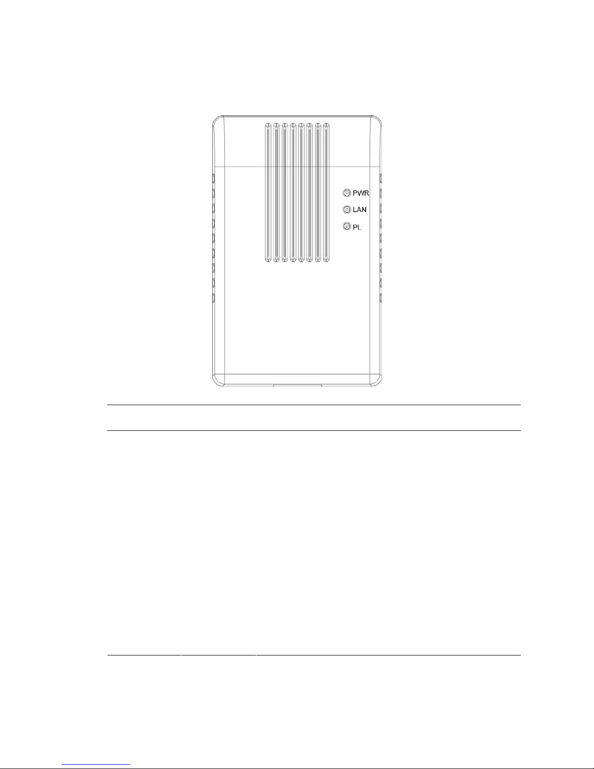
3. LED Definitions
LED Light Status Description
PWR(Green) On The device is powered on.
Off The device is powered off or is in Power Saving
mode.
On
The LAN cable is connected to the HomePlug.
LAN(Green)
Off No network connection.
Blinking Network traffic transferring or receiving
On
The device detects another powerline device.
Off The device doesn’t detect another powerline device.
PL(Green)
Blinking Network traffic is transmitting via the power port of
the device.
Note: The device will be in Power Saving mode when it detects no LAN
connection.
Page 5
4
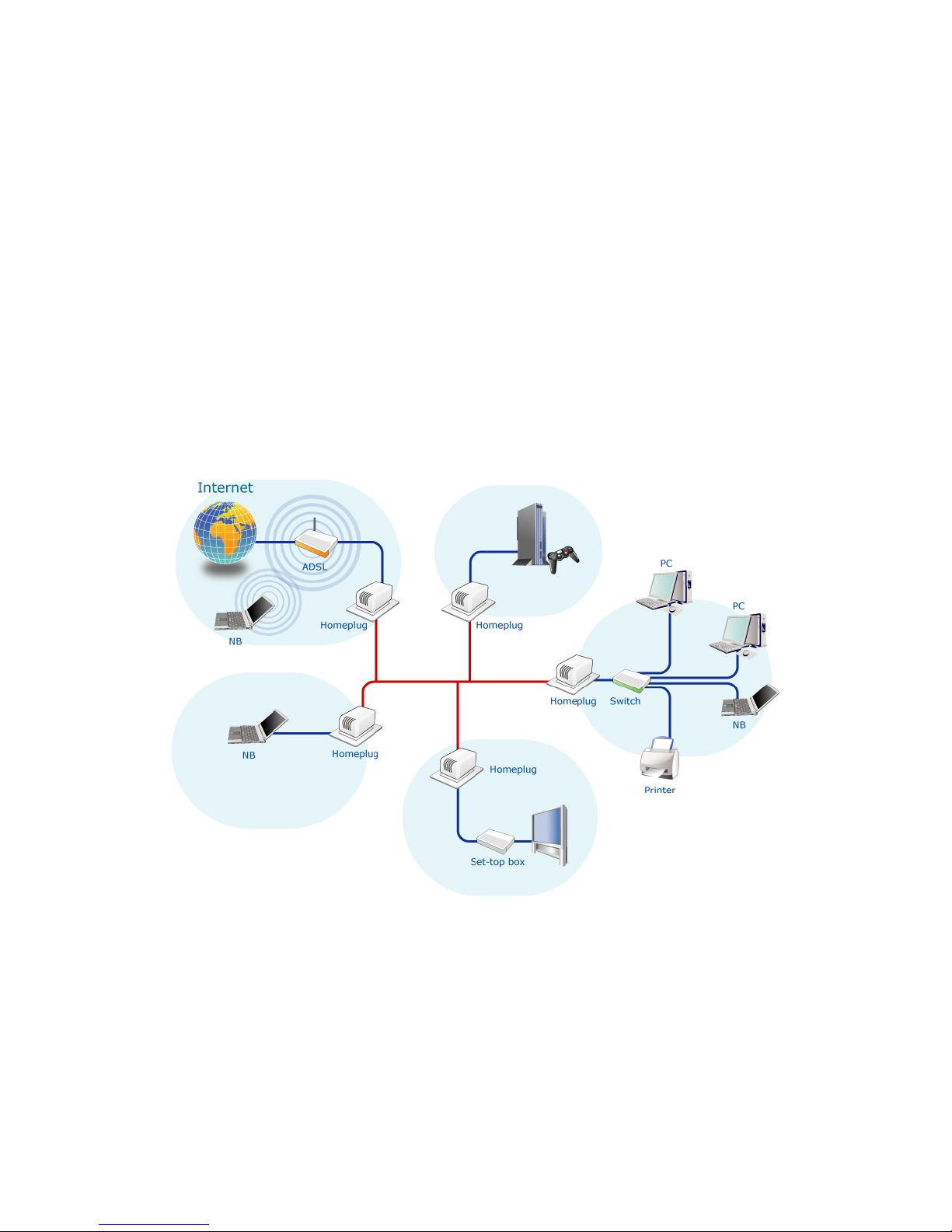
4. Hardware Installation Procedure
1. Unpack the package and verify that all the items listed in the previous
section are provided.
2. Connect the HomePlug product to the device which you want to add to a
powerline network through the Ethernet cable.
3. Plug the HomePlug product to the power outlet.
4. This device with the HomePlug will join in the powerline network
automatically.
The following is the architecture of various applications of the HomePlug
products.
Page 6

5
5. Software Installation Procedure
The Configuration Utility for Windows 98SE/Me/2000/XP/Vista enables the
users to identify HomePlug devices within the powerline network, measures
data rate performance, ensures privacy and performs diagnostics by setting
user defined secure powerline networks.
Please follow the procedures below to install the utility. Please note that the
following procedures are running in Windows XP, for other Windows operating
systems, the procedures are similar.
1. Execute the “Setup.exe” program from “Utility” folder in the CD supplied
with the product.
2. The following screen will be displayed. Click “Next”.
Page 7

6
3. Please enter User Name and your company name here. If you want to
install this utility only for you use, select “Only for me”. Click “Next”.
4. Click “Next” to install the utility in the default folder or click “Change” to
specify the destination folder where you would like to install the HomePlug
utility.
Page 8

7
5. The system starts installing the HomePlug utility.
6. Click “Finish” to complete the installation.
Page 9

8
6. PowerPacket Utility
Click “Start” and select “All Programs\PowerPacket” in your computer, you will
find the HomePlug utility. Please refer to the following sections for the
descriptions of how to use the utility.
5.1 Main
The Main screen provides lists of all HomePlug devices logically connected to
the computer when the utility is running. After connecting a HomePlug device
to you computer, the utility will auto scan other HomePlug devices in the same
network.
Upper Panel
The upper panel shows all local HomePlug devices connected to the
computer’s NIC (Network Interface Card). In most cases, only one device will
be seen. In situations where there are more than one local device being
connected, such as a USB or an Ethernet adapter, the user can select the
local device by clicking on it and then click the “Connect” to connect to the
selected device. Once connected to the local device, the utility will
automatically scan the power line periodically for any other HomePlug
Page 10

9
devices.
Lower Panel
The lower panel displays all the HomePlug remote devices, discovered on the
current logical network. In the top of the table, you can see the total number of
remote devices connected on the same network, the Network type (Public or
Private) of the network and the scanning status.
Device Name: shows the default device name, which may be user re-defined.
A user can change the name by either clicking on the “Rename” button or by
clicking on the name and editing in-place.
An icon is usually shown with the name. A color distinction in icons is made
between HomePlug 1.0 and Turbo devices. By default, the icon is always
accompanied by a device name.
Password: by default the password column is blank and ‘Enter Password’
button can be used to enter it.
To set the Password of the device (it is required when creating a private
network), first select the device by clicking on its name in the lower panel and
then click on the “Enter Password”. A dialog box will appear. The selected
device name is shown above the password field and the password can be
verified by hitting the OK button. The Password field accepts the Device
password in any case formats, with or without dashed between them.
Note 1: The device must be present on the power line (plugged in) in order for
the password to be confirmed and added to the network. If the device could
not be located, a warning message will be shown.
Note 2: Please find the password of the HomePlug device in the rear panel.
The “DEK” code is the password.
Page 11

10
Quality: the status of the connection quality will be shown here.
Rate (Mbps): show the current data rate of the HomePlug device.
MAC Address: the device’s MAC address will be shown here.
Add Button: it is used to add a remote device to the existing network by
entering the device password of the device. A dialog box will appear as below.
The dialog box allows the user to enter both a device name and the
password.
A confirmation box will appear if the password was entered correctly and if the
device was found in the powerline network. If a device was not found, the user
will be notified and suggestions to resolve common problems will be
presented.
Page 12

11
Scan Button: the button is used to perform an immediate search of the
HomePlug devices connected to the Powerline network. By default, the utility
automatically scans every few seconds and updates the display screen.
5.2 Privacy
The Privacy screen provides the user with an option to maintain security for
their logical network and also to select the devices that has to be included in
the network.
Page 13

12
Private Network Name: All HomePlug devices are shipped using a default
logical network (network name), which is normally “HomePlug”. If you wan to
set a privacy network, change the network name.
Use Default (Public Network): The user can always reset to the HomePlug
network (Public) by entering “HomePlug” as the network name or by clicking
on the “Use Default (Public Network)”.
Set Local Device Only: The button can be used to change the private
network name to all of the local devices. If a new network name is entered, all
the devices seen on the top panel of Main screen prior to this will be no longer
present in the new network. You have to set the new network name to all local
devices.
Set All Devices: The button is used to set the new network name (network
password) to all HomePlug devices whose password has been entered for the
same logical network. A dialog window will appear to report the success of this
operation. For devices whose password is not entered, this operation will fail
and will report a failure message.
Page 14

13
5.3 Diagnostics
The Diagnostics screen shows System information and a history of all remote
devices seen over a period of time.
Upper Panel
The Upper panel shows technical data concerning software and hardware
present on the host computer which were used to communicate over
HomePlug on the Powerline network. It includes powerline network name,
computer user name, MAC Address of all NICs (Network interface card)
connected to the computer, versions of all drivers and utilities, etc.
Lower Panel
The Lower panel contains a history of all remote devices seen on the
computer over a certain period of time. All devices that were on the powerline
network are listed here along with a few other parameters. Devices that are
active on the current logical network will show a transfer rate in the Rate
column; devices on other networks, or devices that may no longer exist are
shown with a “?” in the Rate column. The following remote device information
is available from the diagnostics screen:
Device Alias Name
Page 15

14
Device MAC Address
Device Password
Device Last known rate
Device Last Known Network name
HomePlug chipset manufacturer name
Date device last seen on the network
MAC Firmware Version. (Turbo Only)
The diagnostics information displayed may be saved to a text file for later use,
or can be printed for reference for a technical support call. Devices, which are
not part of the network anymore, can be deleted using the delete button. A
dialog window pops up with a confirmation message if we try to delete a
device whose password has been entered.
Page 16

15
5.4 About
The About screen shows the software version information. You can select
“AutoScan” to turn on or off the auto-scan function.
 Loading...