

Page 1

PowerLINE 2000 Adapters
User Manual
Model
PLP2000
December 2017
202-11809-01
350 E. Plumeria Drive
San Jose, CA 95134
USA
Page 2

PowerLINE 2000
Support
Thank you for purchasing this NETGEAR product.You can visit www.netgear.com/support to register your
product, get help, access the latest downloads and user manuals , and join our comm unity.We recommend that
you use only official NETGEAR support resources.
Trademarks
©NETGEAR, Inc., NETGEAR and the NETGEAR Logo are trademarks of NETGEAR, Inc. An y non-NETGEAR
trademarks are used for reference purposes only.
Compliance
For current EU Declaration of conformity, visit http://support.netgear.com/app/answers/detail/a_id/11621.
For regulatory compliance information, visit http://www.netgear.com/about/regulatory.
See the regulatory compliance document before connecting the power supply.
2
Page 3

Contents
Chapter 1 Your PowerLINE Adapter
PLP2000 Adapter...................................................................................................5
LED Descriptions...................................................................................................6
Button Descriptions................................................................................................7
Ethernet Port..........................................................................................................7
Extra Outlet............................................................................................................7
Adapter Label.........................................................................................................7
Chapter 2 PowerLINE Networks
How the PowerLINE Adapter Fits Into Your Network..............................................9
Set Up a New PowerLINE Network......................................................................10
Add an Adapter to an Existing PowerLINE Network............................................12
About PowerLINE Network Security....................................................................13
Use the Security/Factory Reset Button to Set the Encryption Key......................13
Chapter 3 Troubleshooting
LEDs Are Off When the PowerLINE Device Is Plugged In...................................16
Power LED Is Off.................................................................................................16
Ethernet LED Is Off..............................................................................................16
Appendix A Technical Specifications and Safety Information
PowerLINE PLP2000 Technical Specifications....................................................18
Safety Information................................................................................................19
3
Page 4

Your PowerLINE Adapter
This chapter describes your Po werLINE adapter and ho w your adapter fits into a home netw ork. It also explains
the security features and how to secure your PowerLINE network with a private encryption key.
The chapter contains the following sections:
• PLP2000 Adapter
• LED Descriptions
• Button Descriptions
• Ethernet Port
• Extra Outlet
• Adapter Label
For more information about the topics covered in this manual, visit the NETGEAR support website at
netgear.com/support.
1
4
Page 5
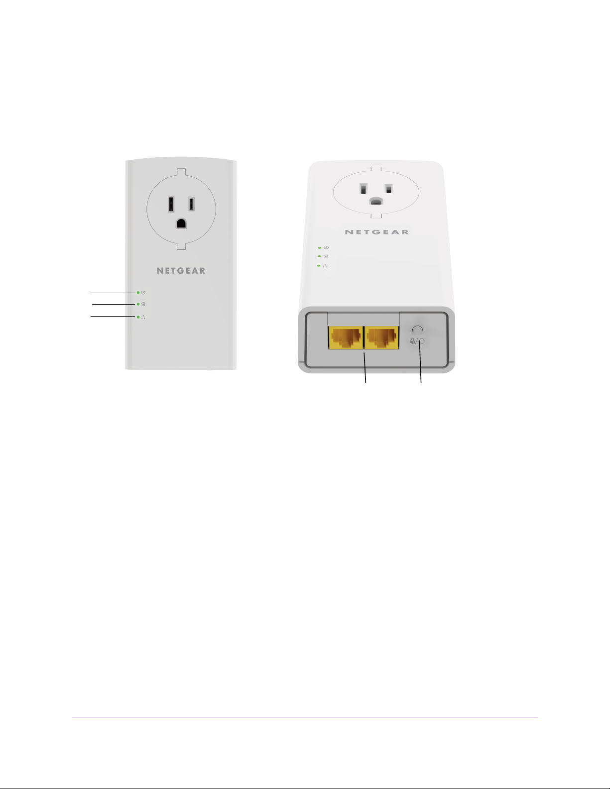
1
2
3
4 5
PowerLINE 2000
PLP2000 Adapter
The hardware features of your PowerLINE adapter are shown in the following figure. Note that adapters
vary by region.Your adapter might look different.
Figure 1. Hardware features
Power LED1
Pick A Plug LED2
Ethernet LED3
Ethernet ports4
Security/Factory Reset button5
Your PowerLINE Adapter
5
Page 6
PowerLINE 2000
LED Descriptions
The LEDs indicate the status of your PowerLINE adapter.
Table 1. LED descriptions
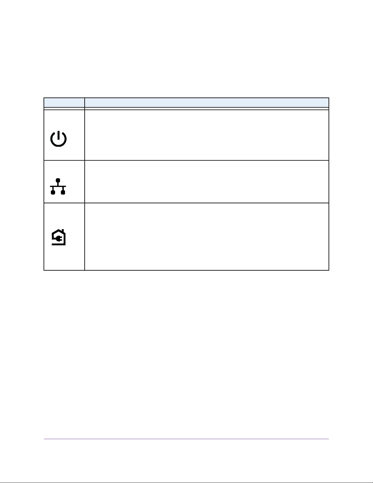
DescriptionItem
Power LED
Ethernet LED
Pick A Plug
LED
Solid green.The electrical power is on.
Blinking green. (Blink rate about once a second) The adapter is in the process of setting up security.
Slow blinking green. (Blink rate about once every three seconds) The adapter is in power saving
mode.
Off.The adapter is not receiving electrical power.
Solid green.The Ethernet port is linked.
Off. No Ethernet connection is detected.
The Pick A Plug feature lets you pick the electrical outlet with the strongest performance, indicated
by the color displayed by the LED:
Red. Link rate < 50 Mbps (good).
Amber. Link rate > 50 and < 80 Mbps (better).
Green. Link rate > 80 Mbps (best).
Off.The adapter did not find any other compatible PowerLINE devices using the same encryption
key.
Your PowerLINE Adapter
6
Page 7

PowerLINE 2000
Button Descriptions
Use the buttons to restore the adapter to the factory configuration and to create a secure network.
Table 2. Button descriptions
DescriptionButton or Switch
Security/Factory Reset
Press and hold the Security/Factory Reset button for 1 to 3 seconds and then release it to create
a secure PowerLINE network.
Press and hold the Security/Factory Reset button for 8 to 10 seconds and then release it to return
the PowerLINE adapter to its factory default settings
Ethernet Port
PowerLINE adapters use Ethernet ports to convert a standard electrical wall outlet into a high-speed wired
network connection.You can use the wired network connection to bring Internet connectivity to any device
with an Ethernet port, such as a computer, game console, Blu-ray player, smart TV, HD set-top box, or
network DVR.
Extra Outlet
For models with an extra outlet, you must observe a few restrictions on how you use the extra outlet.
The technical specifications for your model provide socket outlet ratings. See Technical Specifications and
Safety Information on page 17. See Safety Information on page 19 for general guidelines for use.
Adapter Label
The adapter label provides unique details specific to your device. It displays the following:
• Model number
• MAC address
• Serial number
• Device password
Your PowerLINE Adapter
7
Page 8

PowerLINE Networks
This chapter describes the setup and configuration of PowerLINE networks.
The chapter contains the following sections:
• How the PowerLINE Adapter Fits Into Your Network
• Set Up a New PowerLINE Network
• Add an Adapter to an Existing PowerLINE Network
• About PowerLINE Network Security
• Use the Security/Factory Reset Button to Set the Encryption Key
2
8
Page 9

PowerLINE 2000
How the PowerLINE Adapter Fits Into Your Network
You can use one or more PowerLINE adapters to extend Internet access throughout your home.
A PowerLINE network consists of two or more compatible PowerLINE devices that communicate with each
other using your electrical power lines. One of the PowerLINE devices is connected with an Ethernet cable
to your router so that the PowerLINE network is linked to your local area network (LAN). Connecting one
Pow erLINE device to your router allo ws all the Po werLINE devices on the P owerLINE network to communicate
with the router and use its Internet connection.
The following illustration sho ws a PowerLINE network with one PowerLINE device in Room 1 and a second
PowerLINE device in Room 2.
Figure 2. Poweline adapters connecting two rooms
To form a PowerLINE network, you need at least two compatible PowerLINE devices.
PowerLINE Networks
9
Page 10

PowerLINE 2000
For best performance, follow these guidelines when you plan the location of your PowerLINE devices:
• Use an electrical outlet that is not controlled by a wall switch to a void accidentally turning off the power
to the outlet.
• Avoid plugging P o werLINE products into electrical outlets that are located near appliances that consume
a lot of power, such as washers, dryers, or refrigerators. Interference from these appliances might
prevent PowerLINE products from working correctly or reduce PowerLINE network performance.
• Do not plug PowerLINE products into a power strip, extension cord, or surge protector. Connecting a
Pow erLINE product to one of these devices might prevent the product from working correctly or reduce
PowerLINE network performance.
Set Up a New PowerLINE Network
You can use two or more Po werLINE adapters to f orm a network or extend an e xisting netw ork to additional
wired Ethernet devices.
Pow erLINE networks use an encryption key common to all adapters on the network.Y ou can use the def ault
key or a private key.We recommend that you use a private key.This procedure sets a private key.
To set up a new PowerLINE network:
1. If you are extending an existing wired network, make sure that your wired Ethernet connections are
working by navigating to a web page from a computer connected to your router or gateway using an
Ethernet cable.
2. Plug one PowerLINE device into a wall outlet near your router or gateway.
PowerLINE Networks
10
Page 11

PowerLINE 2000
3. Connect the device to the LAN port on your router or gateway using an Ethernet cable.
4. Plug the second PowerLINE device into a wall outlet where you want to add Internet access.
5. Use the Ethernet cable that came with your adapter to connect the PowerLINE device to an Ethernet
port on a computer, game console, Blu-ray player, or other peripheral device.
6. Wait until the Pick A Plug LEDs are lit.
7. To use a private encryption key, press the Security/Factory Reset button on one of the adapters for
two seconds, and then press the Security/Factory Reset button on the other adapter f or tw o seconds .
Both buttons must be pressed within two minutes.
WARNING:
Do not press the Security/Factory Reset button on the PowerLINE adapter
until installation is complete and the adapters are communicating with each
other (indicated by the blinking Power LED). Pressing this button too soon
can temporarily disable PowerLINE communication. If this occurs, use the
Factory Reset button to return the PowerLINE adapter to its factory default
settings.
The Security/Factory Reset button does not work in power saving mode.Note
8. Wait for the PowerLINE network to recognize each PowerLINE device.
This process could take as little as 5 seconds or up to 80 seconds.
When the Power LEDs stop blinking, the process is complete. If the Pick A Plug LEDs are green or
amber, the devices are successfully connected to the PowerLINE network. A red Pick A Plug LED
indicates a slow link rate. In this case, move the PowerLINE device to another electrical outlet with a
faster connection.
9. If you are installing additional adapters, repeat Step 7 with one of the secure adapters and one of the
adapters that is not yet secured.
See Use the Security/Factory Reset Button to Set the Encryption Key on page 13.
PowerLINE Networks
11
Page 12

PowerLINE 2000
Add an Adapter to an Existing PowerLINE Network
You can add additional adapters to an existing PowerLINE network.
To add an adapter to a PowerLINE network:
1. Plug the adapter into a wall outlet where you want to add Internet access.
2. (Optional) Use the Ethernet cable that came with your adapter to connect the adapter to an Ethernet
port on a computer, game console, Blu-ray player, or other peripheral device.
The PowerLINE devices attempt to detect each other and form a PowerLINE network.
3. If you used a private encryption key, press the Security/Factory Reset button on one of the adapters
that is already a part of the network for two seconds, and then press the Security/Factory Reset button
on the new adapter for two seconds.
Both buttons must be pressed within two minutes.
See Use the Security/Factory Reset Button to Set the Encryption Key on page 13.
WARNING:
Do not press the Security/Factory Reset button on the PowerLINE adapter
until installation is complete and the adapters are communicating with each
other (indicated by the blinking Power LED). Pressing this button too soon
can temporarily disable PowerLINE communication. If this occurs, use the
Security/Factory Reset button to return the PowerLINE adapter to its factory
default settings.
The Security/Factory Reset button does not work in power saving mode.Note
4. Wait for the PowerLINE network to recognize each PowerLINE device.
This process could take as little as 5 seconds or up to 80 seconds.
When the Power LED stops blinking, the process is complete. If the Pick A Plug LEDs are green or
amber, the devices are successfully connected to the PowerLINE network. A red Pick A Plug LED
indicates a slow link rate. In this case, move the PowerLINE device to another electrical outlet with a
faster connection.
PowerLINE Networks
12
Page 13

PowerLINE 2000
About PowerLINE Network Security
A PowerLINE network consists of two or more P owerLINE devices using the same network encryption key.
By setting up security, you configure your PowerLINE network to use a private key instead of the default
key. If y ou do not set up security on your netw ork, any one nearby with a PowerLINE network can potentially
use his or her connection to gain access to your network and information that you send over the Internet.
You can use the Security/Factory Reset button on the PowerLINE device to create a private encryption
key and secure your PowerLINE network. See Use the Security/F actory Reset Button to Set the Encryption
Key on page 13.
Use the Security/Factory Reset Button to Set the
Encryption Key
All PowerLINE networks start with the same default encryption key.You can use the Security/Factory
Reset button to replace the default key with a random private key.This is especially relevant in settings
such as apartment buildings, office buildings, dorm rooms, and other more populated areas.
A Pow erLINE device can generate a random private encryption key only once. If you
Note
want to generate a new random key, first reset the PowerLINE device to its factory
default settings. Press the Security/Factory Reset button for two seconds, and then
release it.
To set the encryption key:
1. Make sure that all of the P o werLINE devices that you want to configure are plugged in by checking that
the Power and Pick A Plug LEDs on each device are lit solid green.
Do not press the Security/Factory Reset button on the P o werLINE devices until the
Note
Pow er and Pic k A Plug LEDs on each PowerLINE device are lit solid green. Pressing
the Security/Factory Reset button too soon can temporarily disable PowerLINE
communication. If Po werLINE communication is disabled, reset the P owerLINE de vice
to its factory default settings by pressing the Security/Factory Reset button for two
seconds and then releasing it.
2. Press the Security/Factory Reset button on the first PowerLINE device for two seconds.
The Pow er LED starts blinking after you release the button, and then the P owerLINE de vice automatically
creates a new , randomly gener ated encryption key that all other P o werLINE de vices on the network will
use.
At this point, the PowerLINE devices cannot communicate with each other.
3. Within two minutes of pressing the Security/Factory Reset button on the first P ow erLINE device , press
the Security/Factory Reset button on the second PowerLINE device for two seconds.
You must press both Security/Factory Reset buttons within two minutes.
The Pow er LED starts blinking after you release the b utton.This process allows the second Pow erLINE
device to use the same private encryption key as the first device so that they can communicate.
PowerLINE Networks
13
Page 14

PowerLINE 2000
When the Power LEDs stop blinking and the Pick A Plug LEDs are lit solid green, the two devices can
communicate over the PowerLINE network in a secure way.
PowerLINE Networks
14
Page 15

Troubleshooting
You can take various steps to diagnose and solve problems that you might encounter.
The first step in troubleshooting your P o werLINE adapter is to chec k the LEDs . After you plug in the PowerLINE
device, the following sequence of events occurs:
1. The Power LED lights.
2. After approximately 10 seconds, verify the following:
• The Power LED is solid green. The device is powered on.
• If the device is connected to a PowerLINE network, the Pick A Plug LED is lit.
• If the PowerLINE device is connected through the Ethernet port to a powered-on Ethernet device, the
Ethernet LED is lit.
If no LEDs are lit, see LEDs Are Off When the PowerLINE Device Is Plugged In on page 16.
If the Power LED is not lit, see Power LED Is Off on page 16.
3
If the Ethernet LED is not lit, see Ethernet LED Is Off on page 16.
If you do not find the solution here, visit the NETGEAR support site at support.netgear.com for product and
contact information.
15
Page 16

PowerLINE 2000
LEDs Are Off When the PowerLINE Device Is Plugged In
The common reason the LEDs are off is that power is not being provided to the device.
Make sure that power is supplied to the electrical outlet.
Power LED Is Off
If the Power LED is off, the adapter is not receiving electrical power.You can try several troubleshooting
tips.
Try these steps:
1. Make sure that power is supplied to the electrical outlet and that the PowerLINE device is not plugged
into an extension cord, power strip, or surge protector.
2. Press the Security/Factory Reset button on the PowerLINE device for 8 to 10 seconds to return the
device to its factory default settings.
Ethernet LED Is Off
If the Ethernet LED is off, the Ethernet port on the adapter is not linked.You can try various troubleshooting
tips.
Try these steps:
1. If your PowerLINE device is connected to the LAN port of your router, make sure of the following:
• Your router and modem are turned on.
• The computer connected directly to the router can access the Internet.
2. If your P owerLINE de vice is connected to a computer, game console, Blu-ray play er , or other peripheral
device, make sure of the following:
• The peripheral device is turned on.
• The PowerLINE device is securely connected to the peripheral device using an Ethernet cable.
3. Press the Security/Factory Reset button on each PowerLINE device for 8 to 10 seconds to return the
device to its factory default settings.
Troubleshooting
16
Page 17

Technical Specifications and Safety
Information
This appendix provides technical specifications and safety information for PowerLINE adapters.
• PowerLINE PLP2000 Technical Specifications
• Safety Information
A
17
Page 18

PowerLINE 2000
PowerLINE PLP2000 Technical Specifications
The PLP2000 adapter meets the technical specifications defined in the following table.
Table 3.Technical specifications
SpecificationFeature
Data and routing
protocols
load)
Weight
MAC addresses
Data transfer rate
IEEE 802.3 (10BASE-T), IEEE 802.3u (100BASE-T), IEEE
802.3ab (1000BASE-T)
100–240V, 0.2A (max.)AC input
AU: 10A, 250V; FR: 16A, 250V; NA: 11.8A, 125VSocket-outlet rating (max.
Normal: 6.5W; Power saving mode: < 0.5WPower consumption
5.25 x 2.83 x 1.49 in. (133.5 x 72 x 37.8 mm)Dimensions
AU: 0.536 lb (243 g); FR: 0.551 lb (250 g); NA: 0.514 lb
(233 g)
0° to 40°C (32º to 104ºF)Operating temperature
10–90% maximum relative humidity, noncondensingOperating humidity
5–95% maximum relative humidity, noncondensingStorage humidity
128-bit AESSecurity encryption type
Number of nodes that can be added to a single network:
8 (active), 16 (total)
2000 MbpsBandwidth
Up to 2000 Mbps with real throughput greater than 500
Mbps
2–86 MHzFrequency band
OFDM windowed modulationModulation type
Technical Specifications and Safety Information
18
Page 19

PowerLINE 2000
Safety Information
Follow these safety guidelines to ensure your own personal safety and to help protect your system from
potential damage:
• For national approvals (approval schemes other than CB), relevant national standards for plug,
socket-outlet, and direct plug-in units (for example, US) shall also be consulted while you are testing
and approving such products according to the national standards.
• Check the electrical current for any device plugged into the filtered AC socket. Do not exceed home
and product outlet ratings and electrical requirements.
• The socket-outlet shall be installed near the equipment and be easily accessible.
• Only power cords are allowed to be inserted into the filtered AC sock et; no other equipment with a direct
plug-in is allowed. Power cords must be a maximum of 1 m long and a minimum of 0.75 mm2 of
cross-sectional area.
• Do not plug devices into the PowerLINE PassThru Adapter filtered AC outlet that exceed the product
ratings.The output voltage of the filtered AC outlet is the same as the power outlet that the P owerLINE
PassThru Adapter is plugged into.To help avoid damaging your system, be sure that the attached
devices are electrically rated to operate with the power available in your location.
• If the input AC voltage is less than 100 VAC, the device plugged into the filtered AC socket of the
PowerLINE PassThru Adapter might not perform as well as expected.
• DO NOT PLUG MAJOR HOME APPLIANCES into the filtered AC socket or into an attached power
strip.The device is not intended to be used with home appliances such as air conditioners, power tools,
space heaters, fans, hair dryers, ovens, or refrigerators.
• Actual data throughput will vary. Network conditions and environmental factors, including volume of
network traffic, building materials and construction, and network overhead, low er actual data throughput
rate.
• Do not service any product except as explained in your system documentation.
• Opening or removing covers that are marked with the triangular symbol with a lightning bolt can e xpose
you to electrical shock. Only a trained service technician should service components inside these
compartments.
• Use the product only with approved equipment.
• Allow the product to cool before removing covers or touching internal components.
• T o help a void damaging y our system, be sure that the voltage selection s witch (if provided) on the power
supply is set to match the power available at your location:
- 110 volts (V), 60 hertz (Hz) in most of North and South America and some Far Eastern countries
such as South Korea and Taiwan
- 100V, 50 Hz in eastern Japan and 100V, 60 Hz in western Japan
- 230V, 50 Hz in most of Europe, the Middle East, and the Far East
Technical Specifications and Safety Information
19
Page 20

PowerLINE 2000
• The peripheral power cables are equipped with three-prong plugs to help ensure proper grounding. Do
not use adapter plugs or remove the grounding prong from a cable.
• Observe extension cable and pow er strip ratings . Make sure that the total ampere rating of all products
plugged into the extension cable or power strip does not exceed 80 percent of the ampere ratings limit
for the extension cable or power strip.
Technical Specifications and Safety Information
20
 Loading...