

Page 1

Reference Manual for the
ProSafe Network
Management System
NMS100
NETGEAR, Inc.
4500 Great America Parkway
Santa Clara, CA 95054 USA
202-10058-01
September 2004
September 2004 202-10058-01
Page 2

© 2004 by NETGEAR, Inc. All rights reserved. September 2004.
Trademarks
NETGEAR is a trademark of Netgear, Inc.
SNMPc, SNMPc W orkgroup, SNMPc Enterprise, and Castle Rock Computing are trademarks of Castle Rock
Computing. Air Messenger Pro is a trademark of Internet Software Solutions. Microsoft, Windows, and Windows NT
are registered trademarks of Microsoft Corporation. Other brand and product names are registered trademarks or
trademarks of their respective holders.
NETGEAR ProSafe Network Management System is based on the SNMPc Network Management System, developed
and exclusively owned by Castle Rock Computing, of California, U.S.A., at www.castlerock.com. NETGEAR ProSafe
Network Management System is Copyright © 1998-2004, by Castle Rock Computing. All Rights Reserved. Each
separate computer installation of NETGEAR ProSafe Network Management System must use a unique Software
License Key.
Statement of Conditions
In the interest of improving internal design, operational function, and/or reliability, NETGEAR reserves the right to
make changes to the products described in this document without notice.
NETGEAR does not assume any liability that may occur due to the use or application of the product(s) or circuit
layout(s) described herein.
Customer Support
Refer to the Support Information Card that shipped with your ProSafe Network Management System. ProSafe NMS
includes free installation support for the first 30 days. Customer support after the initial 30 day period is of fered as a feebased per-incident service. Please go to the Sales page at http://www .netgear.com for more information.
World Wide Web
NETGEAR maintains a World Wide Web home page that you can access at the URLhttp://www.netgear.com. A direct
connection to the Internet and a Web browser su ch as Internet Explorer or Netscape are required.
ii
September 2004 202-10058-01
Page 3

Contents
Chapter 1
Introduction
Audience, Scope, Conventions, and Formats ................................................................2-1
Overview ................................... ................ ................ ................. ................ ................ .....2-2
Other ProSafe NMS Features ........................................................................................2-2
ProSafe Network Management System .........................................................................2-3
System Requirements ....................................................................................................2-3
Device Access Modes ....................................................................................................2-3
None (TCP Only) ......................................................................................................2-4
ICMP (Ping) ..................................... ... .... ... ... ... ....................................... ... ... .... ... ... ..2-4
SNMP V1 and V2c ...................................................................................................2-4
SNMP V3 .................................................................................................................2-4
Package Contents ..........................................................................................................2-4
Chapter 2
Installation and Startup
Installing the ProSafe NMS Server and Local Console ..................................................3-1
Installing the Air Messenger Pro Paging Software .........................................................3-2
Starting the ProSafe NMS Server and Local Console ....................................................3-2
Disabling Automatic Console Login .........................................................................3-3
Starting a Local Console Session ............................................................................3-3
Stopping and Starting the Server ........... ... ... ... ... .... ... ... ... .... ... ... ... .... ... ... ... ... .... ... ... ..3-3
Disabling Automatic Start up of ProSafe NMS Server System Tasks ......................3-3
Console Elements ..........................................................................................................3-4
Console Button Commands .....................................................................................3-5
Edit Button Bar ..................................................................................................3-5
Selection Tool ...........................................................................................................3-6
Event Log Tool .........................................................................................................3-6
View Window Area ...................................................................................................3-7
Contents i
July 2004 202-10036-01
Page 4

Chapter 3
Data and Statistics
Working with the Map Database .....................................................................................4-1
The Map Selection Tree ...........................................................................................4-1
Using Map View Windows ........................................................................................4-2
Moving Map Objects .......................................................................................................4-3
Moving Objects at the Root Level ............................................................................4-3
Moving Objects Inside Subnet Levels ......................................................................4-4
Moving Objects from One Subnet to Another ..........................................................4-5
Changing Object Properties ...........................................................................................4-6
Attributes ............................... ................................................................. ..................4-6
Access Parameters ..................................................................................................4-7
Type-Dependent Attributes ................ .... ... ... ... ... .... ... ... ... .... ... ..................................4-8
Adding Map Objects ................................................. .... ... ... ... .... ... ... ... .... ... ...................4-10
Viewing Device MIB Data .............................................................................................4-11
The MIB Selection Tree .........................................................................................4-11
Manage Menus ......................................................................................................4-11
Custom Menus .......................................................................................................4-12
Table Display Elements ................................................................................................4-12
Graph Display Elements ...............................................................................................4-13
Graph Styles ..........................................................................................................4-13
Graph Page Controls .......................................................................................4-14
Graph Legend Control .....................................................................................4-14
Saving Long-term Statistics ..........................................................................................4-14
Creating a New Report ................................. ... ... .... ... ... ... .......................................4-14
Viewing Trend Data in a Graph Window ................................................................4-15
Limiting Saved Instances .......................................................................................4-16
Chapter 4
Polling and Emailing
Setting Threshold Alarms ............ .... ... ... ... .... ... ... ... ... .... ... ...............................................5-1
Setting Status Variable Polling .................................................................................5-2
Configuring Automatic Alarms ..................................................................................5-2
Setting Manual Threshold Alarms ..................................................................................5-3
Polling TCP Application Services ...................................................................................5-4
Discovery of Four Built-in Services ..........................................................................5-4
ii Contents
July 2004 202-10036-01
Page 5

TCP Service Polling .................................................................................................5-4
Custom TCP Service Polling ....................................................................................5-5
Managing Polling for the Device ............................ ... ... ... .... ... ... ...............................5-5
Emailing or Paging the Administrator on an Event .........................................................5-6
Other Event Types ................. ... ... .... ...................................... .... ... ... .............................5-10
Emailing or Paging Multiple Users ...................... ................... .................... ...................5-11
Chapter 5
Troubleshooting and Advanced Configuration
Troubleshooting Network Discovery ...............................................................................6-1
Duration of Network Discovery .................................................................................6-1
Normal Discovery Map Layout .................................................................................6-1
Failure Symptoms and Solutions .............................................................................6-2
Discovery Agent Fails to Connect to the Server ......................................................6-3
Incorrect or Missing Community Names ..................................................................6-3
SNMP Device Access Control List ...........................................................................6-4
Firewalls Block SNMP Operations ...........................................................................6-4
Not Enough Seeds ...................................................................................................6-4
Broadcast Packet Losses .........................................................................................6-5
Limiting the Scope of Discovery ...............................................................................6-5
Setting Up New Filters .............................................................................................6-5
Stopping Discovery Auto-Layout ...................................................... ........................ 6-6
Appendix A
Event Parameters ...........................................................................................................1-1
Glossary
List of Glossary Terms ...................................................................................................G-1
Index
Contents iii
July 2004 202-10036-01
Page 6

iv Contents
July 2004 202-10036-01
Page 7
Chapter 1
Introduction
Audience, Scope, Conventions, and Formats
This reference manual assumes that the reader has basic to intermediate computer and Internet
skills. This guide uses the following typographical conventions:
Table 1-1. Typographical Conventions
italics Emphasis, books, CDs, URL names
bold User input
SMALL CAPS Screen text, file and server names, extensions, commands, IP addresses
This guide uses the following format to highlight special messages:
Note: This format is used to highlight information of importance or special interest.
This manual is written for the ProSafe NMS according to these specifications.
Table 1-2. Manual Scope
Product Version ProSafe Network Management System
Manual Publication Date September 2004
Note: Product information and updates are available on the NETGEAR Web site at
http://kbserver.netgear.com.
Introduction 1-1
September 2004 202-10058-01
Page 8

Reference Manual for the ProSafe Network Management System NMS100
Overview
ProSafe NMS uses the popular SNMP management protocol to poll and configure devices,
workstations, and servers over IP networks. Along with all the features expected in any SNMP
management station, ProSafe NMS also includes the following advanced features:
• Scalable to 1,000 devices.
• SNMPv1, SNMPv2c and secure SNMPv3 support.
• Event forwarding, and email and pager notifications.
• Audit events for user actions (login and editing).
• Application Service (TCP) polling.
• Long-term trend reports.
• Custom MIB tables with derived MIB expressions.
• RMON-I user interface application.
• GUI device support development tools.
• Application programming interfaces with samples.
Other ProSafe NMS Features
This document has only described some of the most commonly used ProSafe NMS features.
ProSafe NMS is a full-featured distributed network management system that will meet your most
demanding needs. These are some of the other features that you will find described in the Online
Help system.
• Running tasks as Windows Services
• Windows Task Bar Control Icon
• Private MIB Import
• User audit events (login and map edit)
• Custom MIB T ables
• Custom MIB Expressions
• Custom menus
• Graphical device views
• MIB variable browser
• RMON user interface
1-2 Introduction
September 2004 202-10058-01
Page 9

Reference Manual for the ProSafe Network Management System NMS100
• Alarm box event action
• Event forwarding
• Running external programs
• Automatic Icon and Program selection
• Programming interfaces
ProSafe Network Management System
This is a single user version for managing small to medium sized networks. ProSafe NMS can be
used on Windows 2000, 2003, NT, XP, ME, and 98 systems. All components run on a single
system and support one user. The map database size is limited to 1,000 objects.
System Requirements
The following table lists the minimum recommended system requirements.
Table 1-3. Recommended system requirements
Parameter ProSafe NMS
CPU Pentium II 600 MHz
Memory 128 MB
Disk Free 500 MB
Screen 800 x 600
Mouse Required Yes
Console Operating System Win XP/2K/2K3/NT/ME/98
Device Access Modes
ProSafe NMS supports various device access modes including TCP only, ICMP (Ping), SNMP
V1, SNMP V2c and SNMP V3. Each mode is briefly described below.
Introduction 1-3
September 2004 202-10058-01
Page 10

Reference Manual for the ProSafe Network Management System NMS100
None (TCP Only)
Null access is used for polling TCP services only, where ICMP (Ping) and SNMP access is
restricted by a firewall.
ICMP (Ping)
ICMP (Ping) mode is used for devices that do not support SNMP but can still be pinged to see if
they are responding. This may include servers and workstations.
SNMP V1 and V2c
SNMP V1 and SNMP V2c are very similar SNMP agent protocols that are used by most currently
deployed network devices. Any device that supports V2c will generally also support V1. ProSafe
NMS uses automatic intelligence to switch from one mode to the other as needed. So in most cases
select SNMP V1 as the device access mode for any SNMP device.
Since SNMP V1 and V2c are the most common and simplest SNMP protocols, this guide will only
show you how to use these protocols.
SNMP V3
SNMP V3 is a secure SNMP agent protocol that supports authentication and privacy (encryption).
The use of SNMP V3 is considered an advanced topic. As such, this guide does not describe V3 in
any detail. For more information about using V3, please use the Help/Help Topics menu and
search for Setting Device Access Modes in the Index.
Package Contents
The product package should contain the following items:
• Software CD, including:
— ProSafe NMS Software
—This guide
• Software license key
• Customer support card
If any of the parts are incorrect, missing, or damaged, contact your NETGEAR dealer. Please
remember to keep your software CD and license key in a secure location.
1-4 Introduction
September 2004 202-10058-01
Page 11

Reference Manual for the ProSafe Network Management System NMS100
Introduction 1-5
September 2004 202-10058-01
Page 12

Reference Manual for the ProSafe Network Management System NMS100
1-6 Introduction
September 2004 202-10058-01
Page 13
Chapter 2
Installation and Startup
Installing the ProSafe NMS Server and Local Console
1. Log on to Windows with administrator permission.
2. Insert the ProSafe NMS CD into the computer CD
drive.
3. Use the Windows Start/Run menu and enter
d:\NMSsetup, where d: is the CD drive.
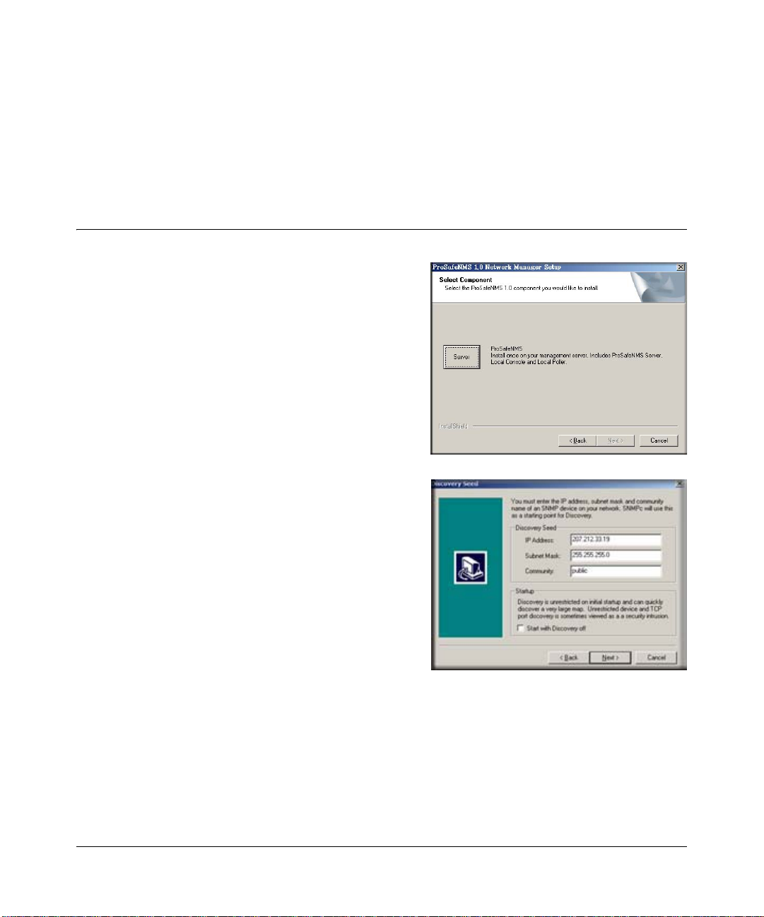
The install program shows a dialog with three
buttons for the installable ProSafe NMS options.
On your main ProSafe NMS system, you only need
to install the Server component, as this includes a
local console and polling agent.
4. Click the Server button.
You are prompted for the installation directory.
Then the Discovery Seed dialog is displayed. You
must enter valid information at this dialog or
network discovery will not work properly.
5. Enter the IP Address of an SNMP Seed Device on
your network, preferably a router.
6. Enter the Subnet Mask for the Seed Device.
7. Enter the SNMP V1 Read Community for the seed
device.
The install program installs ProSafe NMS on your hard drive.
8. After the installation is complete, log off Windows and re start your computer.
Installation and Startup 2-1
September 2004 202-10058-01
Page 14
Reference Manual for the ProSafe Network Management System NMS100
Installing the Air Messenger Pro Paging Software
ProSafe NMS includes a copy of the Air Messenger Pro paging application. This software is
required if you want ProSafe NMS to page you when an event occurs. Air Messenger Pro is not
installed as part of the regular ProSafe NMS installation.
To install Air Messenger Pro, use the Windows Start/Programs/NETGEAR ProSafe NMS/Install
Air Messenger Pro menu. Follow the installation instructions.
After you have installed Air Messenger Pro you can configure ProSafe NMS to notify your pager
when an event occurs. Please refer to “Emailing or Paging the Administrator on an Event” for
further instructions.
Starting the ProSafe NMS Server and Local Console
To control ProSafe NMS tasks, you must be
logged on to Windows with administrator
permission.
After installation of the ProSafe NMS Server
component, you are prompted to reboot the
Windows system.
When the system has rebooted and you log on
to Windows, the ProSafe NMS Server and
Console applications automatically start and
you are automatically logged on.
2-2 Installation and Startup
September 2004 202-10058-01
Page 15
Reference Manual for the ProSafe Network Management System NMS100
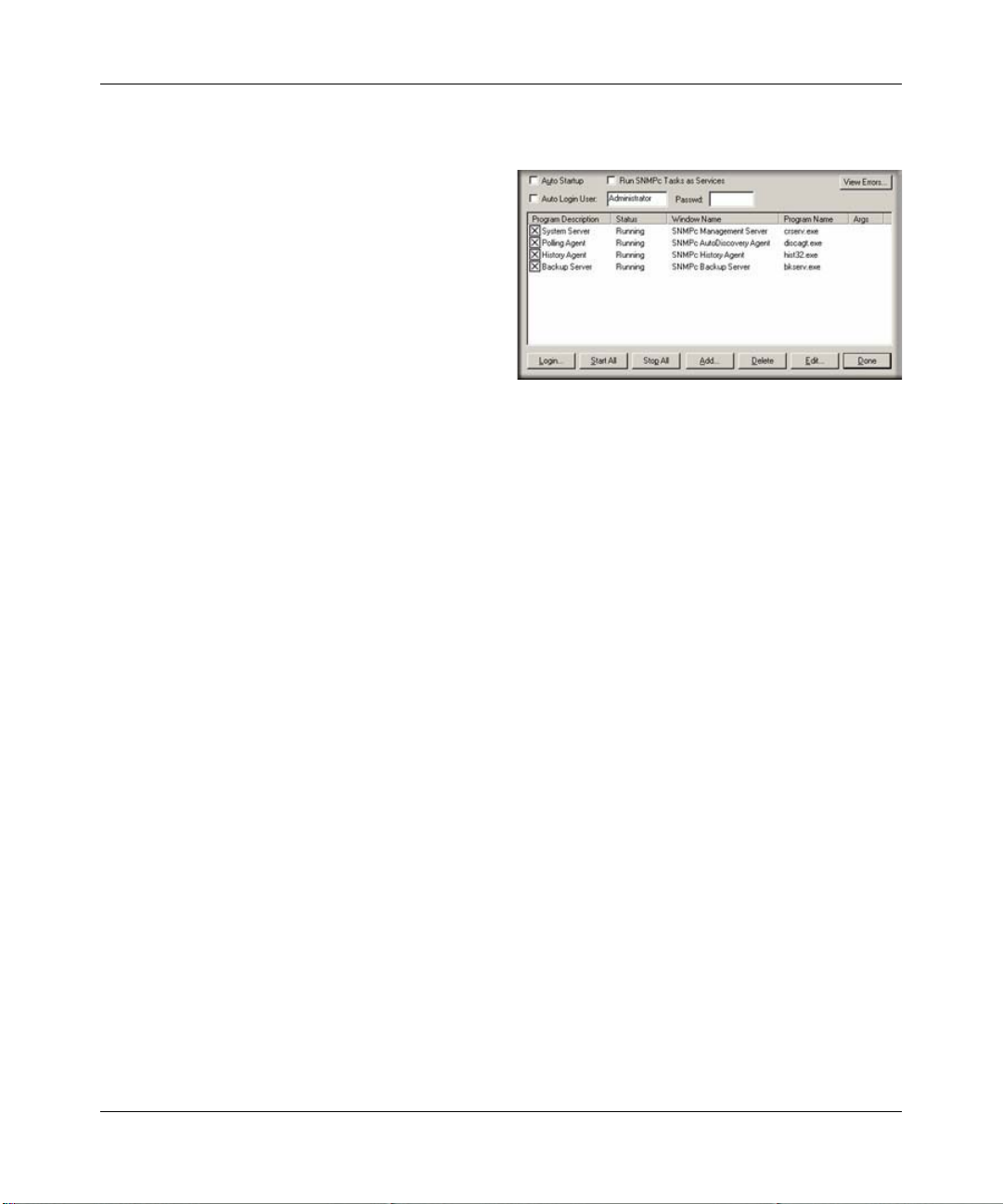
Disabling Automatic Console Login
To disable automatic console startup and login,
go to the Windows Start menu and use the
Programs/NETGEAR ProSafe NMS/Configure
Tasks menu.
Disable the Auto Login User check box and click
the Done button.
Starting a Local Console Session
1. Go to the Windows Start menu and use the Programs/NETGEAR ProSafe NMS/Login
Console menu.
2. At the login prompt, enter localhost as the Server Address.
3. Enter the username and password and click OK.
Initially there is only one user named Administrator with no password.
Stopping and Starting the Server
1. Go to the Windows Start menu and use the Programs/NETGEAR ProSafe NMS/Shutdown
System menu to stop the ProSafe NMS Server system tasks.
2. Use the Windows Start Programs/NETGEAR ProSafe NMS/Startup System menu to restart
the ProSafe NMS Server system tasks.
Note that any running console sessions will be logged off and you will need to exit the console
applications separately.
Disabling Automatic Start up of ProSafe NMS Server System Tasks
1. Go to the Windows Start menu and use the Programs/NETGEAR ProSafe NMS/Configure
Tasks menu.
2. Disable the Auto Startup check box and click Done.
Installation and Startup 2-3
September 2004 202-10058-01
Page 16
Reference Manual for the ProSafe Network Management System NMS100
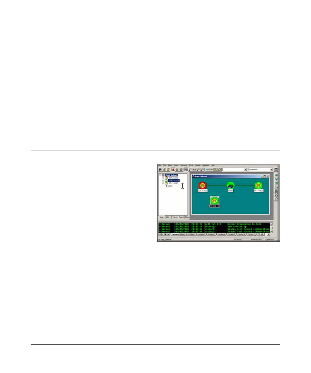
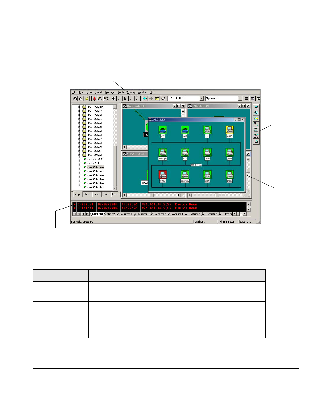
Console Elements
The following figure and table show the main elements of the ProSafe NMS console.
Main button bar
Selection
Tool
Event Log
Tool
Figure 2-1: Console elements
Edit button bar
View Window area
Element Function
Main Button Bar Buttons and controls to execute common commands quickly.
Edit Button Bar Buttons to quickly insert Map elements.
Selection Tool Tabbed control to select obje cts within different ProSafe NMS
functional modules.
Event Log Tool Display filtered Event Log entries.
View Window Area Map View, MIB Tables, and MIB Graph windows are shown here.
2-4 Installation and Startup
September 2004 202-10058-01
Page 17
Reference Manual for the ProSafe Network Management System NMS100
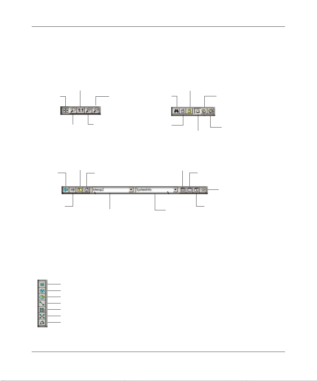
Console Button Commands
The following diagrams show the function of each button in the Main button bar and Edit button
bar. Each of these buttons has a corresponding main menu item.
Normal 1:1
Zoom View
View All
Zoom In
Root Subnet Map View
Map Object
Quick Select
Map View
Back
Map View
Forward
Zoom to
Selected
Rectangle
Map View
Parent
Figure 2-2: Main button bar
Zoom Out
Find
Map
Objects
Edit
Object
Properties
Quick Select
Use
Read/Write
Mode
Show/Hide
Event Log
Display
MIB Table
MIB Object
View Object
Current Events
View
Object
History Events
Tool
Display
MIB Graph
MIB Browser Tool
Device
Quick Poll
Edit Button Bar
Use the Edit button bar to add the objects shown below.
Device Object
Subnet (Hierarchy) Object
Goto Object
Link Between Objects
Bus Network Object
Ring Network Object
Regular Network Object
Figure 2-3: Edit button bar
Installation and Startup 2-5
September 2004 202-10058-01
Page 18

Reference Manual for the ProSafe Network Management System NMS100
Selection Tool
If you do not see the selection tool, use the V iew/ Selection Tool menu to show it. Use the Selection
Tool to manipulate objects from one of several databases. Use the drag control at the right of the
Selection Tool to change its size. Select one of the Selection Tool tabs to display a tree control for
the database. Use the right-click menu inside a selection tree for database-specific commands.
Table 2-1. Selection Tool tabs
Selection Tab Description
Map Map Object database, including devices and subnets.
MIB Compiled SNMP MIBs, Custom Tables and Custom MIB
Expressions.
Trend Report profiles that define long term polling procedures and
scheduled reports.
Event Event filters used to determine what happens when an event
is received.
Menu Custom menus that appear in the Manage, Tools, and Help
ProSafe NMS menus.
Event Log Tool
The Event Log Tool displays different filtered views of the ProSafe NMS event log. If you do not
see the Event Log Tool, use the View /Event Log Tool menu to show it.
• Select the Current tab to show unacknowledged (current) events. These events have a colored
box at the left side of the log entry. The color of map objects is determined by the highest
priority unacknowledged event for that object.
• Select the History tab to show all events, including acknowledged and unacknowledged
events.
• Select one of the Custom tabs and use the right-click Filter V iew menu to spec ify which events
should be displayed for that tab.
• Double-click an event entry to display a Map View window with the corres ponding device
icon visible.
• To quickly view events for a particular device, first select the device and then use one of the
V iew Events buttons (or the View/Active Events and View/History Events menus). This will
show the device events in a separate window in the View Windows a r ea.
2-6 Installation and Startup
September 2004 202-10058-01
Page 19

Reference Manual for the ProSafe Network Management System NMS100
• To remove one or more events, select the event and press the Delete key.
• To acknowledge (remove current status of) an event, select the event and use the right-click
Acknowledge menu.
• To completely clear the event log, use the File/Clear Events menu.
View Window Area
The View Window Area is the main way to view the ProSafe NMS map and command results.
This area uses the Multi-Document-Interface (MDI) specification to display multiple windows at
the same time.
Use the Window/Cascade and Windows/T ile menus to rearrange the windows in the V iew W indow
area in a way that makes them all visible.
Windows in this area can be in one of several states:
•A maximized window uses the entire area and hides any other windows behind it. If you close
a maximized window , the next top-most window wi ll still be displayed in the maximized state.
You need to be careful when using maximized windows because it is easy to lose track of how
many windows you have opened and there is an uppe r limit. Use the Windows menu to see a
list of windows. Use the Windows/Cascade menu to view all windows at the same time.
•An overlapped window does not take up the entire area. One window will be completely
visible and other windows are partially hidden behind it. This is the most common situation for
the View Window area because it lets you view maps, tables and graphs at the same time and
quickly move between them.
•A minimized window is displayed as a small title bar with window Open and Close buttons.
Windows are not typically minimized within the View Window area because, as with the
maximized case, they can easily be lost behind other windows.
Installation and Startup 2-7
September 2004 202-10058-01
Page 20

Reference Manual for the ProSafe Network Management System NMS100
2-8 Installation and Startup
September 2004 202-10058-01
Page 21
Chapter 3
Data and Statistics
Working with the Map Database
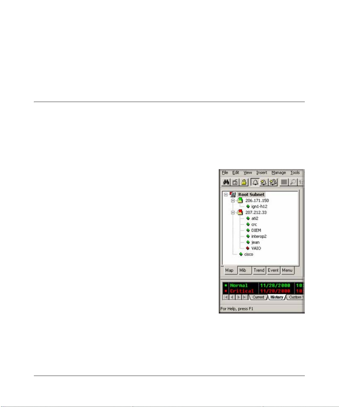
The Map Selection Tree
Locate the Selection T ool on the right side of the console. If you do not see the Selection Tool, use
the View/Selection Tool menu to show it. Select the first tab marked Map. The displayed Map
Selection Tree shows all icon objects in the map. This includes subnets (which contain lower map
levels), devices, and Goto icons. Networks and links are not shown in the Map Selection Tree.
• Single-click the small box to the left of a subnet icon (folder
icon) to open or close that sublevel in the selection tree.
• Double-click on a subnet name (right of folder icon) to open
that subnet level as a Map View window (see below).
• Left-click on any object name to select that object. Use the
Shift and Ctrl keys to select multiple objects.
• Use the Delete key to remove selected objects.
• After opening two subnet levels, select multiple device
names and drag the mouse to move them from one subnet to
another. Note that any attached links and networks are not
moved, and links will be deleted during the move (you can
re-add them manually later).
• Right-click on a device icon (colored rectangle) or name to
see the available right-click menus. Use these menus to edit
the selected object properties, display tables, and run other
custom menus.
• Open a subnet tree and use the Insert/Map Object menus, or the Edit button bar to add icon
objects to the subnet tree.
Each icon in the Map Selection Tree is colored according to the status of the represented object.
Subnet icons (and the top level Root Subnet icon) show the highest priority color of all underlying
objects.
Data and Statistics 3-1
September 2004 202-10058-01
Page 22
Reference Manual for the ProSafe Network Management System NMS100
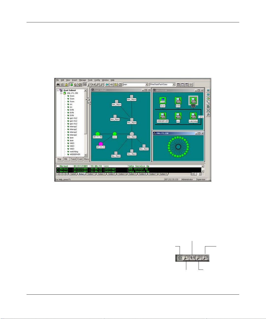
Using Map View Windows
Map View windows are overlapping windows that are displayed in the View Window ar ea of
ProSafe NMS. This is where you can see the map topology as a diagram and easily manipulate the
map objects (add, delete, move). Note that the View Window area shows multiple windows and if
the topmost window is maximized (takes up the entire area) then any other windows will be
hidden. Use the Windows/Cascade menu to show all windows within the View Window area.
• Use the View/Map View/Root Submap menu to show the top level of the ProSafe NMS map.
• Double-click on any subnet name in the Map Selection Tree or subnet icon in a map view to
show a map view for that subnet.
• To easily move the map view, right-click anywhere on the view and drag the mouse to move
the view contents. You can also use the scroll bars, but this is not as easy.
• Use the Zoom buttons to see more or less of the
Map view.
— Use the Pan/Zoom button to zoom into a
View All
Normal 1:1
Zoom View
Zoom Out
selected rectangle (left click and drag the
rectangle).
— Use the 1:1 button to set the normal zoom mode
(icon and name visible).
— Use the Zoom +/- buttons to manually zoom.
3-2 Data and Statistics
September 2004 202-10058-01
Zoom to
Selected
Rectangle
Zoom In
Page 23

Reference Manual for the ProSafe Network Management System NMS100
• Use the View All button to toggle the View All state for a selected map view. In this state, the
view contents are automatically zoomed so that all icons are visible. As you change the size of
the View window, the contents will change size. As the icon sizes get smaller, the icon image
is hidden and then the name is hidden. If your top-level map is large and the View All state is
enabled (default) you may only see small icons. Use the manual Zoom buttons to zoom in to
an area of the map view.
• Use the Previous View and Next View buttons to move back and forth between different zoom
levels you have selected.
Moving Map Objects
ProSafe NMS normally uses a discovery process to add subnets, devices, links, and networks in a
logical topology that represents a two-level IP Subnet hierarchy. The top level includes all router
devices and subnet icons. The second layer includes single-port devices linked to Bus Networks
under the appropriate subnet icons. The top-level map is automatically arranged as a star network.
Map objects are placed on the nearest Map Grid Point when you move them. Use the Config/
Console Options menu and select the Show Grid check box to show map grid points. Set the grid
size in the Grid Spacing edit box.
Moving Objects at the Root Level
Since the discovery agent continually arranges the top map level, before changing the root level
manually you need to change the way discovery works. Use the Config/Discovery-Polling menu
and then do one of the following:
• Clear the Enable Discovery check box so that
discovery is completely disabled.
• Select Discovered Objects from the Layout
pull-down so that any newly discovered objects
are added to a separate subnet icon named
Discovered Objects.
• Select Top Level/Incremental from the Layout
pull-down so that any newly discovered objects
are added using an incremental layout algorithm
that does not disturb the existing layout.
Data and Statistics 3-3
September 2004 202-10058-01
Page 24
Reference Manual for the ProSafe Network Management System NMS100
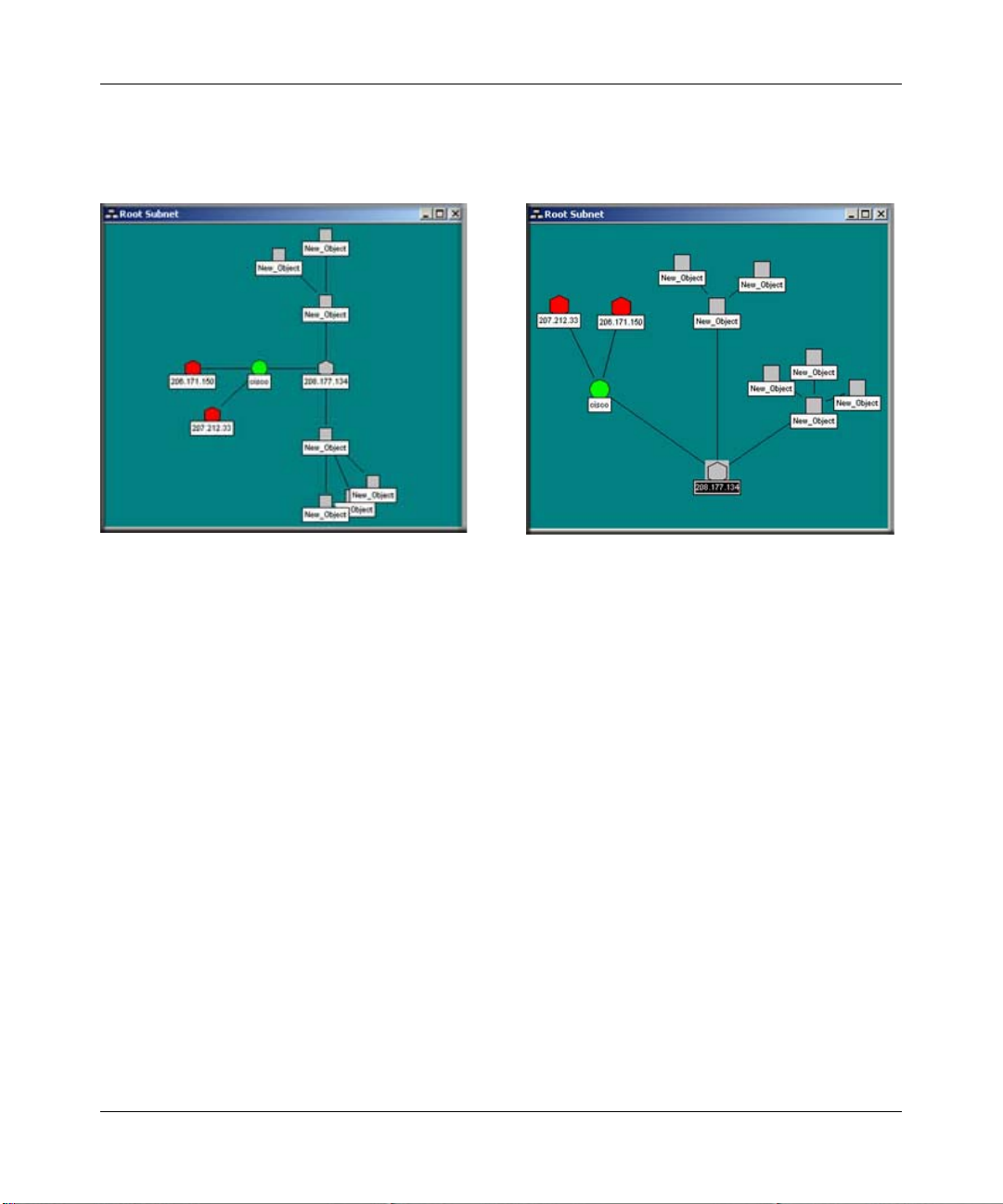
T o move objects at the top level, select one or more objects in a Map view and drag the mouse. The
selected objects are moved to the new mouse location. The following illustration shows an
automatically (left) and manually (right) arranged Root Submap level.
Figure 3-1: Automatically arranged and manually arranged submap levels
Moving Objects Inside Subnet Levels
Single port devices are added to the second map layer, below top-level subnet icons. Each subnet
layer also includes a Bus Network that all devices are attached to. You can move devices around
the Bus Network by selecting them and dragging them to the new position. However, the Bus
Network is automatically arranged and the object will only be approximately placed where you
drag it.
If you need to positively rearrange the lower levels then it is best to change the network from a Bus
to a regular Network. This network will not be automatically arranged and you can move icons
anywhere in the view , as well as change the network shape with junction points . You can click and
drag any junction point or network segment. To add or remove junction points, double-click on the
network.
3-4 Data and Statistics
September 2004 202-10058-01
Page 25
Reference Manual for the ProSafe Network Management System NMS100
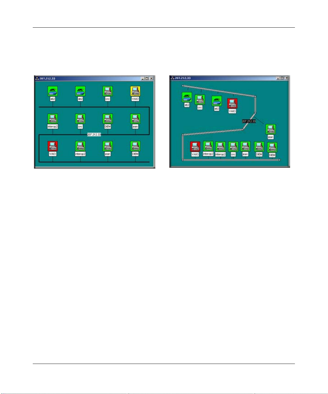
You can also disconnect objects from the Bus Network by deleting the attaching link. Then the
detached object can be moved anywhere in the view. The following figure sh ows a Map view of an
automatically arranged subnet level on the left, and a manually arranged (regular network) subnet
level on the right.
Figure 3-2: Automatically arranged and manually arranged (regular network) subnet levels
Moving Objects from One Subnet to Another
1. Use the Window/Close All menu to remove all View windows.
2. Open a Map view for each of the source and target map subnets.
3. Use the Windows/Tile Horizontal menu to make both windows fully visible.
4. Scroll and zoom the source Map view so the objects you want to move are visible.
5. Scroll and zoom the target Map view so the location where the objects will be placed is visible.
6. Select the objects (click the Off icon+drag or Shift-click on icons) in the source Map view.
7. Drag the selected objects from the source to the target Map view.
Note that any links will be deleted if you only move the attached objects. To move a network and
all attached links and objects you must select all the items. You can also use the Edit/Copy or Cut
menus along with the Edit/Paste menu to move objects (or create copies) but these menus will not
move link or network objects and the moved objects will not retain their relative positions.
Data and Statistics 3-5
September 2004 202-10058-01
Page 26
Reference Manual for the ProSafe Network Management System NMS100
Changing Object Properties
Attributes
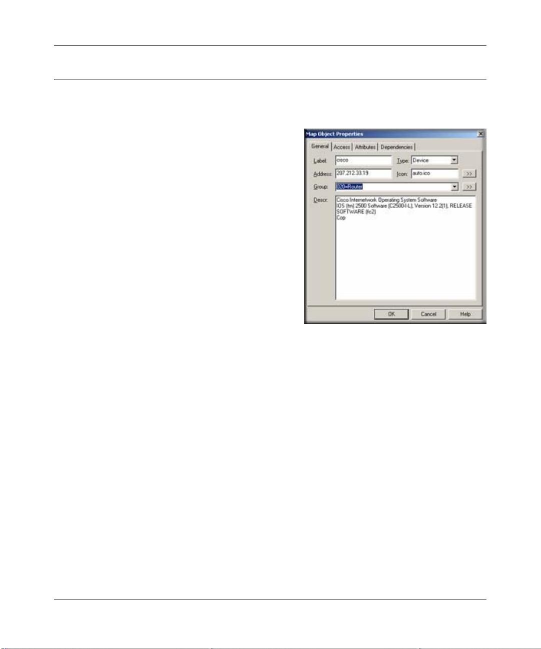
1. Use the Edit/Properties menu to change the
attributes of one or more selected objects. To edit
multiple objects, all selected objects must be of
the same type such as subnet or device.
2. Set the object name in the Label edit box.
3. Set the object type in the Type pull-down. The
object type can only be changed for network type
objects (Ring, Bus, Network).
4. For device objects, set the object IP Address in the
Address edit box. This can be in dot format or a
DNS name. You can also append a UDP port
number to a dot-notation IP address (for example,
198.22.11.22.168).
5. For Goto objects, set the name of the subnet that
the Goto jumps to in the Address edit box.
6. Set an alias name for a group of similar device objects in the Group edit box.
7. For icon type objects (Subnet, Device, Goto), set the icon in the Icon edit box. This is normally
set to
AUTO.ICO so that an icon is selected automatically based on the device SNMP Object
Identifier.
3-6 Data and Statistics
September 2004 202-10058-01
Page 27

Reference Manual for the ProSafe Network Management System NMS100
Access Parameters
1. Select the Access tab to set access parameters for
a Device, Link, or Network object. For a
description of access parameters, please see
Table 3-1 Object Properties Access tab.
2. To change an access parameter, first select the
parameter name in the Attrib table.
The selected parameter name is displayed in the
Name box and the current value is in the Value
pull-down control.
3. In the Value pull-down, select one of the pulldown values or type in a new value.
• Note that the Value pull-down does not
necessarily show all possible values for the
attribute.
• When editing multiple objects, any access parameter that has a different value for different
objects is shown as #####. Changing these attributes will set the new value for all selected
objects.
The following table describes the access parameters available in the Object Properties Access tab
for Device, Link, and Network objects. Access parameters are not valid for Subnet and Goto
object types.
Table 3-1. Object Properties Access tab
Attribute Name Description
Read Access Mode The mode used for polling and SNMP Read operations. Select ICMP
(Ping) for non-SNMP devices. Select SNMP V1 for standard SNMP
devices. Select NONE (TCP Only) for devices that will only have TCP
services polled.
Read/Write Access Mode The mode used for SNMP Write operations. Select SNMP V1 for
standard SNMP devices. You can also force this mode to be used for
both Read and Write operations from your console (not polling
operations) by using the Read/Write button on the ProSafe NMS frame
button bar (third button from left).
Read Community The Community name used for SNMP V1/V2c operations when the
Read Access Mode is used.
Data and Statistics 3-7
September 2004 202-10058-01
Page 28

Reference Manual for the ProSafe Network Management System NMS100
Table 3-1. Object Properties Access tab
Attribute Name Description
Read/Write Community The Community name used for SNMP V1/V2c operations when the
Read/Write Access Mode is used.
Trap Community The Community name expected in a received SNMP V1/V2c Trap
frame. This is used to match an incoming trap to a map object.
V3 Engineid SNMP V3 Engine Identifier (detected automatically).
V3 Context Name VSNMP V3 Context Name (normally blank).
V3 No Auth Security Name SNMP V3 Security Name to use with the noAuth access mode (no
authentication, no privacy).
V3 Auth/Priv Security Name SNMP V3 Security Name to use with authenticated or private
(encrypted) access modes.
V3 Auth Password SNMP V3 password to use for authentication.
V3 Priv Password SNMP V3 password to use for privacy (encryption).
Type-Dependent Attributes
1. Select the Attribute tab to set type-dependent
attributes. For a complete description of all typedependent object attributes, please see Table 3-2
Object Properties Attribute tab.
2. To change an attribute, first select the attribute
name in the Attrib table. The selected attribute
name is displayed in the Name box and the current
value in the Value pull-down control.
3. In the Value pull-down, select one of the pull-down
values or type in a new value.
• Note that the Value pull-down does not
necessarily show all possible values for the
attribute. Use the >> button to show an
expanded selection mechanism for the selected
attribute value.
• When editing multiple objects, any attribute that has a different value for different objects
is shown as #####. Changing these attributes will set the new value for all selected
objects.
3-8 Data and Statistics
September 2004 202-10058-01
Page 29

Reference Manual for the ProSafe Network Management System NMS100
The following table lists each available attribute in the Object Properties Attributes tab, the object
types it is valid for, and a description of the attribute.
Table 3-2. Object Properties Attribute tab
Object
a
Type
S, G, D Background Shape Icon background, one of Square, Circle, Hexagon, Octagon, or
S Bitmap Background bitmap image.
S Bitmap Scale Background bitmap image scaling factor (bigger number expands).
L Show Link Name Link names normally hidden.
D Exec Program Double-click program for devices. Include any of the following
D, L, N Poll Interval Seconds between poll sequences.
D, L, N Poll Timeout Seconds to wait for a response after a poll is sent.
D, L, N Poll Retries Number of times to retry a failed poll during a single poll sequence.
D, L, N Polling Agent IP Address of the Polling Agent system that performs regular and
D, L, N TCP Services List of TCP service names to poll.
D, L, N Status Variable An SNMP variable with instance that is polled to determine device
D, L, N Status Value The number to be compared to the returned Status Variable value.
D, L, N Status OK Expr The expressio n to use when comparing the Status Value to the
D, L, N HasRMON Set to TRUE to enable the RMON tool.
D, L,N MAC Address Primary device MAC address or link MAC address, if known.
D, L, N SNMP ObjectID Read-Only. The System Object Identifier of an SNMP object.
Attribute Name Description
Diamond.
special program arguments: $a – IP Address, $n –‘ node name, $g
– Read Community; $s – Set community, $w – console window
number.
trend statistics polling for this object. Unless you are using Remote
Polling Agents, this is set to localhost.
status (as opposed to just polling for device response). For
example, ifOperStatus.3.
returned Status Variable to determine if the status is OK (<, >, <=,
>=, =, !=).
a. D = Device, L = Link, N = Ring, Bus, Network, S = Subnet, G = Goto
Data and Statistics 3-9
September 2004 202-10058-01
Page 30

Reference Manual for the ProSafe Network Management System NMS100
Adding Map Objects
ProSafe NMS supports several object types, including subnets, devices, links, and networks. To
add objects, first open a Map view window and then use one of the Insert/Map Object menus or the
Edit button bar . After adding icon objects, you need to move them to the desired locat ion. If you do
not see the new object, use the View All button. The following table describes the different object
types.
Table 3-3. Object Types
Type Description
Subnet A Subnet icon contains other map layers, possibly including other subnets.
• Double-click on a subnet icon to open a view window for the next layer down.
• Use the Parent Window button to go up one layer to the parent subnet view.
• Use the Root Subnet button to open the top map level view.
Device A Device icon represents a polled device, including SNMP and Ping polled devices.
1. When adding a device object, set the device Address in the displayed Properties dialog
box. You can append an optional UDP port to the address as x.x.x.Port.
2. Then select the Access tab and set the Read Access Mode and Read/Write Access Mode
parameters. Use ICMP (Ping) for non-SNMP devices (or NONE where you only want to poll
TCP services), and use SNMP V1 for regular SNMP devices. For SNMP V1 devices, you
must also set the Read Community and Read/Write Community pa rameters to valid
community names.
3. Finally, select the Attributes tab and set appropriate values for the Poll Interval, Poll
Timeout, and Poll Retries attributes.
Link A Link object is a line between two icon objects (Subnet, Device, Goto). Link objects can be
polled so you can optionally set an IP Address and Access/Polling attributes as with the Device
object. However, by default the poll Interval for links is set to zero so it is not polled. T o add one
or more Link objects, first select two or more Device objects and optionally a single Subnet or
Network object, then click the Add Link button from the Edit button bar.
Network There are several types of Network objects, which have different layout styles.
• A Bus Network automatically arranges the network and attached links and icons in a bus
configuration.
• A Ring Network automatically arranges the attached objects in a ring.
• A regular Network object can be manually shaped. Double-click on a Regular Network object
to create a junction point. Double-click on an existing junction point to remove it. Click on a
Junction object or network segment and drag it to move it in the Map view.
• Network objects can also be polled but the Poll Interval is set to zero (non-polled) by default.
• Use one of the Add Network buttons from the Edit button bar to add a network. If you first
select several icon objects, ProSafe NMS will also add links between the icons and the new
network.
Goto A Goto object is like a Subnet in that you can double-click on it to open a new Map view
window. However , a Goto object displays the map subnet that is named in the Address field. T o
make a Goto that opens the Root Submap, leave the Address field blank.
3-10 Data and Statistics
September 2004 202-10058-01
Page 31
Reference Manual for the ProSafe Network Management System NMS100
Viewing Device MIB Data
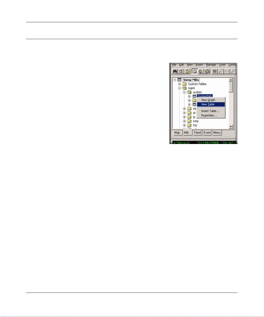
The MIB Selection Tree
1. Select one or more SNMP Device objects.
2. Locate the Selection Tool at the left of the console window.
If you do not see it, use the View/Selection Tool menu to
show it.
3. Click the MIB tab to activate the MIB Selection Tree. This
tree shows all compiled standard and private MIBs.
4. Open the Mgmt subtree to show standard MIB elements.
Open the Private subtree to show vendor-specific MIB
elements.
Note that each device supports a subset of the standard and
private MIBs. It is up to you to determine if a device
supports a particular MIB table.
5. Open subtree elements until you see one or more table grid icons listed. These are the MIB
table definitions that you will be working with.
6. Right-click on one of the table names and use the View Tab l e or View Graph menu to display
the contents of the table for the selected devices as a form or graph.
Manage Menus
Select one or more SNMP Device objects and use the Manage or right-click menus to display
common SNMP MIB tables in several formats. Note that not all devices implement all tables in
these menus, so in some cases the menus will fail to show a result. It is up to you to determine if
the table specified in the menu is supported.
• Use the List <tablename> menus to display a single entry table.
• Use the Edit <tablename> menus to show an edit dialog for a single entry table.
• Use the Display <tablename> menus to display a multi-entry table.
• Use the Graph <tablename> menus to display a graph for all instances in the table. You can
also start a graph after selecting some elements in a displayed table.
Data and Statistics 3-11
September 2004 202-10058-01
Page 32

Reference Manual for the ProSafe Network Management System NMS100
Custom Menus
The Manage menus are actually built-in custom menus from an external configuration file. You
can also add custom menus to display particular tables. For example, if you have only a few device
types in your network you probably should add custom menus to display the vendor specific tables
for those devices. You can then display MIB information using the right-click menus instead of
searching for MIB tables in the MIB Selection Tree. For more information about custom menus,
select the Menu tab of the Selection Tool and press the F1 key.
Table Display Elements
The following figure shows a sample table display and describes the function of table controls.
Save
to File
Poll
Interval
Figure 3-3: Table display and table controls
Edit
Controls
Show
Graph
Pause
Polling Axis
Short
Names
Edit
Entry
Switch
• T o start a graph display, first select one or more cells (rows, columns, or individual cells), then
use the Show Graph button.
• To change a table cell and do a Set Operation to the device, first locate settable cells (those
displayed in blue). Double-click the cell to move into Edit Mode. Enter the new value directly
into the cell (or select from the pull-down if it is displayed). Then click the Check Edit Control
button. To cancel a Set operation in progress, click the Cross Edit Control button.
3-12 Data and Statistics
September 2004 202-10058-01
Page 33

Reference Manual for the ProSafe Network Management System NMS100
Graph Display Elements
The following figure shows a sample graph display and the function of graph controls.
Save
Pause
Graph
Restart
Graph
to File
Graph
Style
Poll
Interval
Vertical
Scale
Paging
Controls
Figure 3-4: Graph display and graph controls
Graph Styles
In the following figure there are four graph styles: Line, Bar, Distribution, and Pie. Note that the
Bar and Pie show Average values.
Data and Statistics 3-13
September 2004 202-10058-01
Page 34

Reference Manual for the ProSafe Network Management System NMS100
Graph Page Controls
The graph is difficult to view with many variables at the same time. Use the Page Controls to
enable blocks of variables. Use the Paginate button (paper sheet icon) to enable all variables or just
the first page (eight variables). Use the Prev Page and Next Page buttons to enable the previous or
next page of variables.
Graph Legend Control
The Legend Control displays all variable names and a data summary, including the Current,
Minimum, Maximum, and Av erage values.
• Drag the bar at the top of the Legend Control to make the control bigger or smaller.
• Double-click the check mark at the left to enable or disable a variable.
• Use the right-click Properties menu to set line properties and scaling for a variable.
• Double-click on the Graph View area to show or hide the Legend Control.
Saving Long-term Statistics
ProSafe NMS Trend Reports save long term statistics for any SNMP table and also ProSafe NMS
Service Polling pseudo-tables. Each report saves data for one table and up to 10 devices. You can
set manual threshold alarms for any variable instance to generate an event when a variable reaches
a specific value. Data is saved in a private format database at one or more polling agent systems.
Data can be downloaded and viewed in a regular graph window for a specified date period.
Creating a New Report
1. Select one or more device objects using the Map Selection Tree or a Map View window.
2. Locate the Selection Tool at the left of the console. If you do not see the Selection Tool, use
the View/Selection Tool menu to show it.
3-14 Data and Statistics
September 2004 202-10058-01
Page 35
Reference Manual for the ProSafe Network Management System NMS100
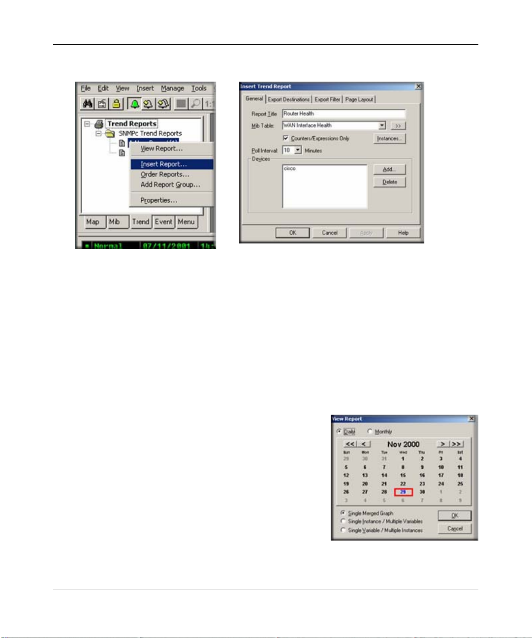
3. Select the Trend tab and open the Trend Reports Group name.
4. Use the right-click Insert Report menu to add a new report.
5. Enter a name for the new report.
6. Select one of the built-in table names from the MIB Table pull-down. You can also click the
>> button to select any standard or private MIB table.
Note: For initial test purposes, set the Poll Interval to one minute. We recommend that you use a
10 minute poll interval if you have several reports.
7. Click OK to save the report using standard settings.
Viewing Trend Data in a Graph Window
1. Assuming you set a one minute poll interval, wait about
10 minutes to save some data.
2. Right-click on the new report name in the Trend Report
Selection Tree and use the Properties menu.
3. Use the View Report menu.
4. Select the current day and Single Merged Graph to see all
data on one graph.
5. Click OK. Some progress dialogs are displayed and then
the report data is displayed in a regular ProSafe NMS
graph window.
Data and Statistics 3-15
September 2004 202-10058-01
Page 36

Reference Manual for the ProSafe Network Management System NMS100
Irrespective of the report poll interval, all Counter variables shown in a trend report graph window
are normalized to per-second values.
Limiting Saved Instances
The polling agent normally polls all available instances for each variable in a trend report table.
1. To limit polled instances, select the report name in the Trend Selection Tree and use the rightclick Properties menu, then use the Instances button.
2. Select one or more rows in the displayed
table and click the Add button to add
them to the Instances Tree at left.
3. In the Instances Tree, select one or more
labels (including <All Other Instances>)
and click the Include or Exclude button.
4. For each included instance, use the Edit
button to set textual instance names and
manual threshold alarms.
3-16 Data and Statistics
September 2004 202-10058-01
Page 37

Chapter 4
Polling and Emailing
Setting Threshold Alarms
You can generate a Threshold Alarm when a polled SNMP variable value meets certain criteria.
ProSafe NMS supports three distinct mechanisms for generating Threshold Alarms as described in
the following table.
Table 4-1. Threshold Alarms
Alarm Type Description
Status Variable Polling Use the Object Properties dialog to set a single SNMP
variable plus instance that is polled in real time (Poll Interval
attribute seconds). Use this for Emergency Status Polling. For
example, poll for UPS battery failure, disk full, or link down
conditions.
Automatic Trend Baseline ProSafe NMS automatically determines a baseline value for
all variables in any trend reports that you add. The baseline is
set after a learning period and periodically adjusted. The
polling agent will generate alarms if a polled value exceeds
the baseline by a preset percentage.
Manual Trend Threshold Use manual threshold alarms in trend reports to specify a
particular condition to test. This is commonly used to monitor
line utilization variables. In this case the alarm condition is well
known to the user and involves a longer polling period (for
example, 80% over 10 minutes).
Polling and Emailing 4-1
September 2004 202-10058-01
Page 38

Reference Manual for the ProSafe Network Management System NMS100
Setting Status Variable Polling
• Using the Map Selection Tree or a Map V iew window,
right-click on an SNMP Device, Link, or Network
object and use the Properties menu.
• Make sure the Address field is set to a valid IP
address. You can optionally append a UDP port
number to the address as x.x.x.x.Port.
• Select the Access tab.
• For a regular SNMP V1 device, set Read Access
Mode to SNMP V1 and set Read Community to a
valid community name.
• Select the Attributes tab.
• Set Poll Interval to the number of seconds between
successive polls.
• Set the Status Variable to the name of an Integer SNMP variable including an instance (e.g.,
ifOperStatus.3). Make sure you enter a full variable instance.
• Set the Status Value to the Numeric value for your comparison (or one of the pull-down
aliases).
• Set the Status OK Expr to the test performed to determine if the status test passes. Use the
Value pull-down list for possible tests.
Note: For variables that have a textual instance part, you can use the form statusVar.”text instance”
rather than full SNMP dot notation.
Configuring Automatic Alarms
Use the Config/Trend Reports menu and select the Automatic Alarms tab. You can set various
parameters of the automatic alarm algorithm in this dialog. Generally the default settings are
adequate and the main thing you might want to do is disable automatic alarms by clearing the
Enable Automatic Alarms check box.
4-2 Polling and Emailing
September 2004 202-10058-01
Page 39

Reference Manual for the ProSafe Network Management System NMS100
Setting Manual Threshold Alarms
You must first create a trend report for a set of devices and an SNMP MIB Table. Please refer to
Saving Long-term Statistics for a description of creating trend reports.
Select the report name in the Trend Selection Tre e and use the right-click Properties menu, then
use the Instances button.
1. Select one or more rows in the
displayed table and click the Add
button to add them to the Instances
Tree at the left.
2. In the Instances Tree, select one or
more labels (including <All Other
Instances>) and click the Include or
Exclude button.
3. For each included instance, use the
Edit button to add alarms for each
variable.
4. Select a variable name from the list at the bottom
of the Instance Edit dialog.
5. Enter a simple expression at the Threshold edit
box. This is an operator (>, <, =, >=, <=, !=) and a
numeric constant.
You can also optionally enter a name for this
variable instance in the Instance Name edit box.
This makes it easier to determine what the
threshold alarm refers to.
6. Click OK. You will see a red exclamation mark
next to the icon in the Instances Tree for any
instances that have manual alarms.
Please keep in mind that for Counter variables, the
values you set in the manual threshold will be compared against a polled sample. The polled
sample will be larger or smaller depending on the trend report poll interval. For example, a link
that shows 100K bytes in one minute might show 1,000K bytes in 10 minutes. This is different
than what you see in trend graph, in which the samples are normalized to per-second values.
Polling and Emailing 4-3
September 2004 202-10058-01
Page 40
Reference Manual for the ProSafe Network Management System NMS100
Polling TCP Application Services
ProSafe NMS supports customized polling of any TCP application service and simplified polling
of four built-in TCP application services (FTP, SMTP, Web, and Telnet).
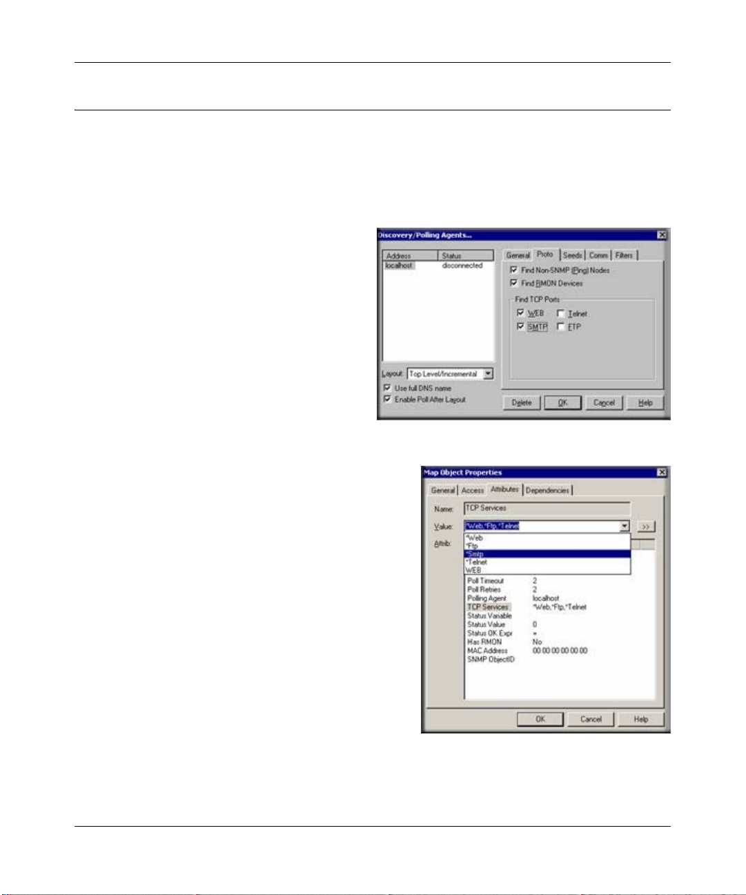
Discovery of Four Built-in Services
ProSafe NMS polling agents can automatically
check for the existence of the built-in TCP
services on discovered devices and configures
these services to be polled.
Use the Proto tab of the Config/DiscoveryPolling dialog to enable discovery of the four
built-in services.
TCP Service Polling
1. To enable TCP service polling for a device, rightclick the device object in a Map view and use the
Properties menu then select the Attributes tab.
Select the TCP Services attribute.
2. Use the Value pulldown list to select one of the
available TCP services (*Ftp, *Telnet, *Smtp,
*Web and custom names).
3. To select multiple services for the device, type in
the service names in the Value edit box, separated
by commas. For example: “*Ftp,*Web”.
4. Alternatively, double-click the TCP Services
attribute, or use the “>>” button, to select multiple
services.
4-4 Polling and Emailing
September 2004 202-10058-01
Page 41

Reference Manual for the ProSafe Network Management System NMS100
Custom TCP Service Polling
Custom TCP Service definitions allow more flexible and powerful polling of your application
servers.
• You can optionally send a text string to the TCP service and compare the reply to a text
pattern.
• Each map object can poll up to 16 different Custom TCP Services.
• There is no limit on the total number of Custom TCP Service definitions that can be created.
Double-click the TCP Services attribute, or use the “>>” button, to edit Custom TCP service
definitions. The Poll Services dialog is displayed.
Managing Polling for the Device
Use the controls in the upper portion of the dialog box, Polled Services for this Object, to manage
polling for the selected device.
To enable polling of a TCP service for the device:
1. Select the service name in the All Services list.
2. Click the Add>> button.
To disable polling of a TCP service for the device:
1. Select the service name in the All Services list.
2. Click the Del<< button.
Use the controls in the lower Edit Custom Services
section to add, delete, and change Custom TCP Service
definitions.
To add a new Custom TCP Service definition:
1. Enter a new name in the Service Name edit box.
2. Enter a TCP port number for the service in the TCP Port edit box.
Optionally enter a short string to transmit to the service in the Send String edit box.
Optionally enter a pattern string to match against the service response in the Expect String edit
box. You may use ASCII text and asterisk wildcards (‘*’).
3. Click the Add button.
Polling and Emailing 4-5
September 2004 202-10058-01
Page 42

Reference Manual for the ProSafe Network Management System NMS100
4. After adding a new service definition, you need to click the Add>> button if you want this
service to be polled for the currently selected device.
To delete an existing Custom TCP Service definition:
1. Select the service name in the All Services list.
2. Click the Delete button.
To modify an existing Custom TCP Service definition:
1. Select the service name in the All Services list.
2. Make changes to the Service Name, TCP Port, Send String, or Expect String edit boxes.
3. Click the Change button.
Note that service names prepended by an asterisk are built-in and cannot be changed or deleted.
These services are *Ftp, *Telnet, *Smtp, and *Web. These services use a simplified connect-only
form of polling.
Emailing or Paging the Administrator on an Event
This section shows you how to dial a pager or send email to the ProSafe NMS Administrator user
when a selection of devices goes down.
1. First, add the Administrator user to Air Messenger Pro
a. To use paging you must first install Air Messenger Pro by using the Windows Start/
Programs/NETGEAR ProSafe NMS/Install Air Messenger Pro menu.
b. Start Air Messenger Pro and add a user (not a group) named Administrator.
c. Configure and test the Air Messenger Pro modem/pager settings and make sure you can
send pages.
4-6 Polling and Emailing
September 2004 202-10058-01
Page 43

Reference Manual for the ProSafe Network Management System NMS100
2. Then, set the Email/Paging global event options
a. Use the Config/Event Options menu.
b. Set the SMTP Server Address to the IP Address of your
email server in dot notation (a.b.c.d).
c. Set the Email From Address to an ema il address that is
valid at your server (such as nms-support@netgear.com).
d. Select the Pager Application (Air Messenger Pro or
Notify!Connect).
e. Select the Enable Tracing to History Log check box. Later,
when you have verified that email works you can disable
this option.
3. Next, set the Administrator Contact Information
a. Use the Config/User Profiles menu.
b. Select the Administrator user and click Modify.
c. Set your email address in the E-mail edit box.
d. Select the Pager Type (numeric or alphanumeric).
e. Set the days and times you want to be emailed and
paged.
f. You can use the Group1 and Group2 edit boxes to
set two alias names for multiple users. For now,
leave Group1 set to Default.
Polling and Emailing 4-7
September 2004 202-10058-01
Page 44

Reference Manual for the ProSafe Network Management System NMS100
4. Add an Event Filter for the pollDeviceDown event
a. Locate the ProSafe NMS Selection Tool at the left
side of the console. If it is not there, use the View/
Selection Tool to show it.
b. Select the Event tab on the Selection Tool.
c. Open the Snmpc-Status-Polling subtree, which
contains all polling related event actions.
d. Open the pollDeviceDown subtree, which contains
all event filters for the Device Down event.
e. Right-click on the Default event filter and use the
Insert Event Filter menu to add a new event filter.
The Add Event Filter dialog is displayed.
f. Enter an Event Name for the new event filter at the
General tab. For example, set the name to Primary
Router Down.
5. Select the devices to match the Event Filter
a. Select the Match tab of the displayed Add
Event Filter dialog.
b. Click the Add button.
c. Use the tree control to select one or more
device names and click OK.
d. The matching device names are displayed
in the Sources list box.
4-8 Polling and Emailing
September 2004 202-10058-01
Page 45

Reference Manual for the ProSafe Network Management System NMS100
6. Then, set the Email/Page event actions
a. Select the Actions tab of the displayed Add Event
Filter dialog.
b. Select Default from the Page Group pull-down to
send a page to all users with a Group1 or Group2
alias set to Default (the Administrator user).
c. Select Default from the Email Group pulldown to
send email to all users with a Group1 or Group2
alias set to Default (the Administrator user).
d. Click OK to save the new filter.
7. Finally, test the new Event Filter
a. Select the Map tab of the Selection Tool and
select one of the devices you matched in the
new event filter.
b. Use the Tools/Trap Sender menu.
c. The TrapSend tool shows an Event Actions tree
on the left side. Open the Snmpc-Status-Polling
subtree and select the pollDeviceDown event.
d. Click the Send button.
e. Close the TrapSend tool and look at the Event
Log Tool (at the lower part of the console). If
you do not see the Event Log Tool, use the
View/Event Log Tool menu to show it.
f. Select the History tab in the Event Log T ool. You will see a red Device Down event for the
selected node and some white diagnostic messages about the email operation.
Polling and Emailing 4-9
September 2004 202-10058-01
Page 46

Reference Manual for the ProSafe Network Management System NMS100
Other Event Types
The pollDeviceDown event is an example used in this section. The mechanism is the same for
other types of events, including those generated for Status V ariable and Manual Threshold Alarms.
The following table shows common events and when they occur.
Table 4-2. ProSafe NMS Events
Event Subtree Trap Name Description
Snmpc-Status-Polling pollDeviceDown Device has not responded for three consecutive
poll sequences.
pollNoResponse Device failed to respond to one poll sequence.
pollRequestRejected Device rejected the sysObjectId.0 or the user-set
pollResponse Device responded to a poll sequence.
pollServiceDown Could not connect to the TCP port after three
pollServiceNoResponse Co uld not connect to the TCP port after one
pollServiceResponding Connection to TCP port OK.
pollStatusTestFail Status variable test failed.
pollStatusTestPass Status variable test passed.
Snmpc-System-Info pollAgentConnect SNMPc polling agent connection to server
pollAgentDisconnect SNMPc polling agent connection to server lost.
Snmpc-Threshold-Alarm alarmAutoThresholdExpand Trend auto-baseline moved higher.
alarmAutoThresholdReduce Trend auto-baseline moved lower.
alarmAutoThresholdSet Trend auto-baseline initially set.
alarmAutoThresholdTrigger Trend auto-baseline exceeded.
alarmManualThresholdTrigger Trend manual alarm passed threshold.
alarmManualThresholdReset After being triggered, a trend manual alarm no
snmp-Traps authenticationFailure Trap generated by a device on an illegal access
coldStart Trap generated by a device after it restarts.
linkDown Trap generated by a device when a link fails.
linkUp Trap generated by a device when a link that was
status polling variable.
consecutive attempts.
attempt.
established.
longer passes the threshold test.
(bad community name).
down recovers.
4-10 Polling and Emailing
September 2004 202-10058-01
Page 47
Reference Manual for the ProSafe Network Management System NMS100
Note: A poll sequence occurs repeatedly every POLL INTERVAL seconds. During each poll
sequence, a poll is sent and a reply expected within the P
OLL TIMEOUT period. If no response is
received during the timeout period, the poll is sent again immediately (retried). During a single
poll sequence, retries will be made up to the value set for P
the poll sequence fails. The P
OLL INTERVAL must then elapse before another poll sequence is
OLL RETRIES. If the retries all fail then
attempted.
Emailing or Paging Multiple Users
This section shows how to email or page two users when a selection of devices goes down. Please
read and understand section “Emailing or Paging the Administrator on an Event” on page 5-6
before reading this one.
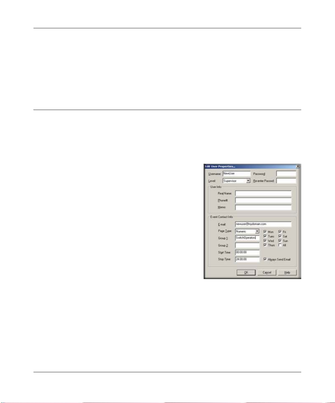
1. First, add a grouped set of users
a. Use the Config/User Profiles menu.
b. Click the Add button.
c. Enter the Name of the new user.
d. Set the user Email address and the user Pager type.
e. Set the email/page days and times.
f. Set the Group1 user alias to SwitchOperators (this
can be any text).
g. Click OK to save the new user.
h. Repeat this process for a different user name,
making sure to set the Group1 value to
SwitchOperators, so that both users have the same
value for Group1 for example, they have the same
alias).
2. Next, add the users to Air Messenger Pro
a. To use paging, start the Air Messenger Pro application and add two users with the same
names as those you added to ProSafe NMS.
Do not use Air Messenger Pro groups and do not use the ProSafe NMS Group1 name.
Each ProSafe NMS user must have a matching user name in Air Messenger Pro.
b. Set up the paging/modem options and make sure that you can send pages for each of the
two new users.
Polling and Emailing 4-11
September 2004 202-10058-01
Page 48

Reference Manual for the ProSafe Network Management System NMS100
3. Then, add an Event Filter for the selected devices
a. Add a new event filter for a set of devices as described in Steps 4 through 7 of “Emailing
or Paging the Administrator on an Event” on page 5-6.
b. In the Action tab, select SwitchOperators in the Page pull-down to page the two new users.
c. Select SwitchOperators in the Email pull-down to send email to the two new users.
d. In the Match tab of the Add Event Filter dialog, make sure that you match different
devices than those used in the previous section (emailing the Administrator). Otherwise,
this new filter will not be unique and it will not match any incoming events.
e. Remember to set the Auto-Clears flags for any matching events.
4-12 Polling and Emailing
September 2004 202-10058-01
Page 49

Chapter 5
Troubleshooting and Advanced Configuration
Troubleshooting Network Discovery
Duration of Network Discovery
During the ProSafe NMS Server installation you entered the address, netmask, and community
name for one SNMP V1 discovery seed device. This is normally enough information to discover
most of your network. When you first start ProSafe NMS it will take several minutes for discovery
to start adding objects to the map. Use the Root Subnet button to display the top-level Map view.
If you used the Disable Discovery on Startup option of the installation, discovery will not be
running when you first start ProSafe NMS. In this case, you need to set discovery filters before
proceeding. Please refer to “Limiting the Scope of Discovery” on page 6-5 before reading this
section.
Normal Discovery Map Layout
Discovery creates a two-level IP Subnet based topology. At the top-level, discovery adds any
multi-port devices (routers) and subnet icons for each IP Subnet. Link objects are added between
each router and the subnets it is connected to. The map is automatically arranged in a star
configuration.
All single-port SNMP devices and ICMP (Ping) devices are added to the second level under each
subnet icon, based on the device IP address and subnet mask. A single Bus Network is added to
each subnet level, and all devices in the subnet are linked to this network.
Use the Root Subnet button to display the top-level Map view. You should see a mixture of SNMP
device icons and subnet icons, connected by links in a star configuration. Double-click on one of
the subnet icons. You should see a Bus Network with devices linked to it in a grid configuration.
Troubleshooting and Advanced Configuration 5-1
September 2004 202-10058-01
Page 50

Reference Manual for the ProSafe Network Management System NMS100
The figure below shows a sample top-level and subnet Map view for a small network. Note that
some devices have vendor-specific icons while others have generic icons. Each generic device
icon is marked as SNMP or ICMP (Ping), which is important in determining discovery problems.
Figure 5-1: Sample top-level and Subnet Map views for a small network
Failure Symptoms and Solutions
The discovery agent uses a heuristic algorithm to find network devices. That means it is somewhat
non-deterministic and will show different results from one run to another. There are many reasons
for this, including lost broadcast responses such as buffer overflows, collisions, lost polls, and
slow responses. This is completely normal. However, there are some permanent failure cases that
you can resolve. The following symptoms are typical of a discovery failure:
1. Nothing added to the map (after a suitable wait period of several minutes).
2. Top-level map only or mostly contains subnet icons, with no links.
3. Some or all SNMP devices are added to lower level subnets as Ping icons.
4. Not all expected network devices are discovered.
The following sections describe solutions to these problems.
5-2 Troubleshooting and Advanced Configuration
September 2004 202-10058-01
Page 51

Reference Manual for the ProSafe Network Management System NMS100
Discovery Agent Fails to Connect to the Server
Look at the Current tab of the Event Log Tool. If you do not see the Event Log Tool, use the View/
Event Log Tool to show it. Scroll to the top of the event log. You should see an entry that says
D
ISCOVERY/STATUS AGENT CONNECTED TO SERVER. Also, use the Config/Discovery-Polling
menu. Y ou should see an entry in the list at the left for your system IP address and the status should
be connected. If these two things are not true then the discovery agent has not properly connected
to the server.
ProSafe NMS uses TCP/IP to communicate between different components. This can conflict with
other software running on your system. Look for any other managemen t applications or Windows
services and stop them (for example, Windows SNMP Trap Service). Try installing on a different
system that has less software installed to help identify the conflicting software. This is a rare
failure case.
Incorrect or Missing Community Names
Each SNMP V1 device uses a Read Community password for SNMP access. This is typically set
to public when the device is installed but in most cases your network administrator has changed
the community name. Furthermore, many different community names may be in use on your
network.
1. Determine what community names are used in
your network devices.
2. Use the Config/Discovery-Polling menu.
3. Select your system address in the agents list.
4. Click the Comm tab.
5. For each community name, click the Add button.
Set the Read Access Mode and Read/Write
Access Mode to SNMP V1 and set Read
Community and Read/Write Community to valid
community names
6. Click OK.
7. Use the File/Reset menu to delete the discovered map and restart discovery.
Troubleshooting and Advanced Configuration 5-3
September 2004 202-10058-01
Page 52

Reference Manual for the ProSafe Network Management System NMS100
SNMP Device Access Control List
Many SNMP devices have an Access Control List (ACL). An ACL is a list of IP addresses from
which the device accepts SNMP requests. This is a vendor-specific security feature that is
configured at the device using a terminal or Telnet session. At a minimum, you need to go to each
Discovery Seed device and check if it has an ACL and that your ProSafe NMS system address is in
the list. For complete network discovery you must add your system address to any ACLs in your
network.
Firewalls Block SNMP Operations
Many networks use firewall devices to stop unauthorized intrusions. It is very usual for firewalls to
block SNMP traffic because SNMP operations can shut down and reconfigu re devices. If you have
any firewalls in your network you need to make sure that your ProSafe NMS system can send and
receive SNMP operations through the firewalls. This is normally done with a protocol filter in
combination with an Access Control List (ACL). Firewall configuration is done with a terminal or
Telnet session.
Not Enough Seeds
ProSafe NMS uses a combination of downloaded seed device information (address, routing, ARP
tables) and broadcasts to discover devices. However, many devices inhibit broadcasts to networks
outside of your LAN (subnet directed broadcasts). To get around this problem you need to add
more seed addresses for routers around your network.
1. Use the Config/Discovery-Polling menu.
2. Select your system address in the agents list.
3. Click the Seeds tab.
4. For each new seed, enter the IP Address and
Subnet mask in the supplied edit boxes and click
Add.
5. Click the General tab and then the Restart button.
6. Click the OK button. There is no need to reset
the map in this case.
5-4 Troubleshooting and Advanced Configuration
September 2004 202-10058-01
Page 53

Reference Manual for the ProSafe Network Management System NMS100
Broadcast Packet Losses
In many cases network discovery mostly works but you do not see as many devices as you expect.
As many devices are not represented in SNMP ARP tables they can only be discovered with
broadcasts. Broadcasts responses can be lost due to buffer overflows or collisions.
To get around this problem you can enable sequential polling of every possible address within a
discovered subnet. Use the Config/Discovery-Polling menu and select the Ping Scan Subnets
check box then click the Restart button.
Note that ProSafe NMS will not poll ranges that you specify, but only discovered subnets. To
discover more subnets, add more seeds as described in the previous section.
Limiting the Scope of Discovery
If you have a large network but you only want to manage a small part of it, you need to set
discovery address range filters. Discovery filters only specify what should be included. So if you
set any discovery filters you must set enough of them to cover any address ranges you want to
discover.
Address range filters are in dot notation with optional wild-card asterisk characters and numeric
range specifiers. Unless the last element is an asterisk, there must be four dot-separated elements.
The following are some valid examples:
207.*
207.212.33.*
207.100-211.*
198.*.*.22-88
Setting Up New Filters
1. Use the Config/Discovery-Polling menu.
2. Select your system address from the agents list.
3. Click the Filters tab.
4. Enter a filter in the Address Range edit box and
click Add.
5. Repeat for other filters.
6. Click OK.
Troubleshooting and Advanced Configuration 5-5
September 2004 202-10058-01
Page 54

Reference Manual for the ProSafe Network Management System NMS100
7. Use the File/Reset menu to delete the current map and restart discovery with the new filters.
Stopping Discovery Auto-Layout
Left unattended, discovery constantly rearranges your top-level map as new devices are added.
This is undesirable if you want to manually change the map layout. To control discovery layout,
use the Config/Discovery-Polling menu and do one of the following:
• Clear the Enable Discovery check box to disable further discovery.
• Select Discovered Objects from the Layout pull-down to add any new objects to a subnet
named Discovered Objects instead of the top-level map.
• Select Top Level/Incremental from the Layout pull-down to add any new objects to the toplevel using an incremental layout algorithm. The existing layout will not be disturbed.
8. Use the T est Interval and Test Retries edit boxes to set the time between checks of the primary
server by the backup server and how many times to retry before taking over polling.
5-6 Troubleshooting and Advanced Configuration
September 2004 202-10058-01
Page 55

Appendix A
Event Parameters
Use Event Parameters in Event Action Filters to substitute information related to a specific event.
Event Parameters can be used in the Event Message and as arguments to a program in the Exec
Program action. The available Event Parameters and the associated expansion are described in the
following table.
Table 5-1. Event Parameters
Event
Parameters
$$ The dollar ($) symbol
$V Event message text (for Exec Program action).
$W Console frame window number.
$M Server IP Address.
$R Address of sending entity (could be the same as the target device, or it could be
a Polling Agent address).
$F Event Action Filter name.
$f Event Action Filter database record number.
$O Trap Name as a textual string.
$o Trap Object Identifier in dot format.
$A Address of target device (device that the event is about)
$T Trap Community Name.
$x Date the event occurred, in local format at server.
$X Time the event occurred, in time zone of server.
$@ Time the event occurred, in seconds since Jan 1, 1970.
$U Value of sysUpTime in the event trap.
$N The map object name of the target device.
$i The map database record number of the target device.
$G The Read Community name of the target device
Description
September 2004 202-10036-01
A-1
Page 56

Reference Manual for the ProSafe Network Management System NMS1000
Table 5-1. Event Parameters
Event
Parameters
$S The Set Community name of the target device.
$E The timeout attribute, in seconds, of the target device
$Y The max retries for the target device
$P The name of the map parent subnet object
$C The number of variables in the event trap.
$* All variables as "[seq] name (type): value".
$-n The nth variable as "name (type): value"
$+n The nth variable as "name: value".
$n The nth variable as “value”
$>n All variables from the nth as "value".
$>-n All variables from the nth as "[seq] name (type): value.
$>+n All variables from the nth as "name: value.
Description
A-2
September 2004 202-10036-01
Page 57

Glossary
Use the list below to find definitions for technical terms used in this manual.
List of Glossary Terms
10BASE-T
IEEE 802.3 specification for 10 Mbps Ethernet over twisted pair wiring.
100BASE-Tx
IEEE 802.3 specification for 100 Mbps Ethernet over twisted pair wiring.
802.1x
802.1x defines port-based, network access control used to provide authenticated network access and
automated data encryption key management.
The IEEE 802.1x draft standard offers an effective framework for authenticating and controlling user traffic
to a protected network, as well as dynamically varying encryption keys. 802.1x uses a protocol called EAP
(Extensible Authentication Protocol) and supports multiple authentication methods, such as token cards,
Kerberos, one-time passwords, certificates, and public key authentication. For details on EAP specifically,
refer to IETF's RFC 2284.
802.11a
IEEE specification for wireless networking at 54 Mbps operating in unlicensed radio bands over 5GHz.
802.11b
IEEE specification for wireless networking at 11 Mbps using direct-sequence spread-spectrum (DSSS)
technology and operating in the unlicensed radio spectrum at 2.5GHz.
802.11g
A soon to be ratified IEEE specification for wireless networking at 54 Mbps using direct-sequence
spread-spectrum (DSSS) technology and operating in the unlicensed radio spectrum at 2.5GHz. 802.11g is
backwards compatible with 802.11b.
ADSL
Short for asymmetric digital subscriber line, a technology that allows data to be sent over existing copper
telephone lines at data rates of from 1.5 to 9 Mbps when receiving data (known as the downstream rate) and
from 16 to 640 Kbps when sending data (known as the upstream rate).
Glossary
September 2004 202-10036-01
1
Page 58

Reference Manual for the ProSafe Network Management System NMS1000
ADSL requires a special ADSL modem. ADSL is growing in popularity as more areas around the world
gain access.
AES
Advanced Encryption Standard, a symmetric 128-bit block data encryption technique.
It is an iterated block cipher with a variable block length and a variable key length. The block length and the
key length can be independently specified to 128, 192 or 256 bits.The U.S government adopted the
algorithm as its encryption technique in October 2000, replacing the DES encryption it used. AES works at
multiple network layers simultaneously.
ARP
Address Resolution Protocol, a TCP/IP protocol used to convert an IP address into a physical address (called
a DLC address), such as an Ethernet address.
A host wishing to obtain a physical address broadcasts an ARP request onto the TCP/IP network. The host
on the network that has the IP address in the request then replies with its physical hardware address. There is
also Reverse ARP (RARP) which can be used by a host to discover its IP address. In this case, the host
broadcasts its physical address and a RARP server replies with the host's IP address.
Auto Uplink
Auto UplinkTM technology (also called MDI/MDIX) eliminates the need to worry about crossover vs.
straight-through Ethernet cables. Auto Uplink
TM
will accommodate either type of cable to make the right
connection.
Cat 5
Category 5 unshielded twisted pair (UTP) cabling. An Ethernet network operating at 10 Mbits/second
(10BASE-T) will often tolerate low quality cables, but at 100 Mbits/second (10BASE-Tx) the cable must be
rated as Category 5, or Cat 5 or Cat V, by the Electronic Industry Association (EIA).
This rating will be printed on the cable jacket. Cat 5 cable contains eight conductors, arranged in four
twisted pairs, and terminated with an RJ45 type connector. In addition, there are restrictions on maximum
cable length for both 10 and 100 Mbits/second networks.
Denial of Service attack
DoS. A hacker attack designed to prevent your computer or network from operating or communicating.
DHCP
An Ethernet protocol specifying how a centralized DHCP server can assign network configuration
information to multiple DHCP clients. The assigned information includes IP addresses, DNS addresses, and
gateway (router) addresses.
DMZ
A Demilitarized Zone is used by a company that wants to host its own Internet services without sacrificing
unauthorized access to its private network.
2 Glossary
September 2004 202-10036-01
Page 59

Reference Manual for the ProSafe Network Management System NMS1000
The DMZ sits between the Internet and an internal network's line of defense, usually some combination of
firewalls and bastion hosts. T ypically, the DMZ contains devices accessible to Internet traffic, such as Web
(HTTP) servers, FTP servers, SMTP (e-mail) servers and DNS servers.
DNS
Short for Domain Name System (or Service), an Internet service that translates domain names into IP
addresses.
Because domain names are alphabetic, they're easier to remember. The Internet however, is really based on
IP addresses. Every time you use a domain name, therefore, a DNS service must translate the name into the
corresponding IP address. For example, the domain name www.example.com might translate to
198.105.232.4. The DNS system is, in fact, its own network. If one DNS server doesn't know how to
translate a particular domain name, it asks another one, and so on, until the correct IP address is returned.
Domain Name
A descriptive name for an address or group of addresses on the Internet. Domain names are of the form of a
registered entity name plus one of a number of predefined top level suffixes such as .com, .edu, .uk, etc. For
example, in the address mail.NETGEAR.com, mail is a server name and NETGEAR.com is the domain.
DoS
A hacker attack designed to prevent your computer or network from operating or communicating.
DSL
Short for digital subscriber line, but is commonly used in reference to the asymmetric version of this
technology (ADSL) that allows data to be sent over existing copper telephone lines at data rates of from 1.5
to 9 Mbps when receiving data (known as the downstream rate) and from 16 to 640 Kbps when sending data
(known as the upstream rate).
ADSL requires a special ADSL modem. ADSL is growing in popularity as more areas around the world
gain access.
DSLAM
DSL Access Multiplexor. The piece of equipment at the telephone company central office that provides the
ADSL signal.
Dynamic Host Configuration Protocol
DHCP. An Ethernet protocol specifying how a centralized DHCP server can assign network configuration
information to multiple DHCP clients. The assigned information includes IP addresses, DNS addresses, and
gateway (router) addresses.
EAP
Extensible Authentication Protocol is a general protocol for authentication that supports m ultiple
authentication methods.
EAP, an extension to PPP, supports such authentication methods as token cards, Kerberos, one-time
passwords, certificates, public key authentication and smart cards. In wireless communications using EAP, a
user requests connection to a WLAN through an AP, whi ch then req uests the iden tity of the user and
Glossary
September 2004 202-10036-01
3
Page 60

Reference Manual for the ProSafe Network Management System NMS1000
transmits that identity to an authentication server such as RADIUS. The server asks the AP for proof of
identity, which the AP gets from the user and then sends back to the server to complete the authentication.
EAP is defined by RFC 2284.
ESP
Encapsulating Security Payload.
ESSID
The Extended Service Set Identification (ESSID) is a thirty-two character (maximum) alphanumeric key
identifying the wireless local area network.
Gateway
A local device, usually a router, that connects hosts on a local network to ot her networks.
IETF
Internet Engineering Task Force. Working groups of the IETF propose standard protocols and procedures for
the Internet, which are published as RFCs (Request for Comment) at
www.ietf.org.
An open international community of network designers, operators, vendors, and researchers concerned with
the evolution of the Internet architecture and the smooth operation of the Internet.
IP
Internet Protocol is the main internetworking protocol used in the Internet. Used in conjunction with the
Transfer Control Protocol (TCP) to form TCP/IP.
IP Address
A four-byte number uniquely defining each host on the Internet, usually written in dotted-decimal notation
with periods separating the bytes (for example, 134.177.244.57).
Ranges of addresses are assigned by Internic, an organization formed for this purpose.
IPX
Short for Internetwork Packet Exchange, a networking protocol used by the Novell NetWare operating
systems.
Like UDP/IP, IPX is a datagram protocol used for connectionless communications. Higher-level protocols,
such as SPX and NCP, are used for additional error recovery services.
ISP
Internet service provider.
Internet Protocol
The main internetworking protocol used in the Internet. Used in conjunction with the Transfer Control
Protocol (TCP) to form TCP/IP.
LAN
A communications network serving users within a limited area, such as one floor of a building.
4 Glossary
September 2004 202-10036-01
Page 61

Reference Manual for the ProSafe Network Management System NMS1000
LDAP
A set of protocols for accessing information directories.
Lightweight Directory Access Protocol
LDAP. A set of protocols for accessing information directories.
LDAP is based on the standards contained within the X.500 standard, but is significantly simpler. And
unlike X.500, LDAP supports TCP/IP, which is necessary for any type of Internet access. Because it's a
simpler version of X.500, LDAP is sometimes called X.500-lite.
local area network
LAN. A communications network serving users within a limited area, such as one floor of a building.
A LAN typically connects multiple personal computers and shared network devices such as storage and
printers. Although many technologies exist to implement a LAN, Ethernet is the most common for
connecting personal computers.
MAC address
The Media Access Control address is a unique 48-bit hardware address assigned to every network interface
card. Usually written in the form 01:23:45:67:89:ab.
Mbps
Megabits per second.
MDI/MDIX
In cable wiring, the concept of transmit and receive are from the perspective of the computer, which is wired
as a Media Dependant Interface (MDI). In MDI wiring, a computer transmits on pins 1 and 2. At the hub,
switch, router, or access point, the perspective is reversed, and the hub receives on pins 1 and 2. This wiring
is referred to as Media Dependant Interface - Crossover (MDI-X). See also AES.
Maximum Receive Unit
The size in bytes of the largest packet that can be sent or received.
Maximum Transmit Unit
The size in bytes of the largest packet that can be sent or received.
Most Significant Bit or Most Significant Byte
MSB. The portion of a number, address, or field that is farthest left when written as a single number in
conventional hexadecimal ordinary notation. The part of the number having the most value.
MRU
The size in bytes of the largest packet that can be sent or received.
MSB
MSB. The portion of a number, address, or field that is farthest left when written as a single number in
conventional hexadecimal ordinary notation. The part of the number having the most value.
Glossary
5
September 2004 202-10036-01
Page 62

Reference Manual for the ProSafe Network Management System NMS1000
MTU
The size in bytes of the largest packet that can be sent or received.
NAT
A technique by which several hosts share a single IP address for access to the Internet.
NetBIOS
The Network Basic Input Output System is an application programming interface (API) for sharing services
and information on local-area networks (LANs).
Provides for communication between stations of a network where each station is given a name. These names
are alphanumeric names, up to 16 characters in length.
Network Address Translation
NAT. A technique by which several hosts share a single IP address for access to the Internet.
NIC
Network Interface Card. An adapter in a computer which provides connectivity to a network.
NID
Network Interface Device. The point of demarcation, where the telephone line comes into the house.
packet
A block of information sent over a network. A packet typically contains a source and destination network
address, some protocol and length information, a block of data, and a checksum.
Perfect Forward Secrecy
Perfect Forward Secrecy (PFS) provides additional security by means of a Diffie-Hellman shared secret
value. With PFS, if one key is compromised, previous and subsequent keys are secure because they are not
derived from previous keys.
PKIX
PKIX. The most widely used standard for defining digital certificates.
Point-to-Point Protocol
PPP. A protocol allowing a computer using TCP/IP to connect directly to the Internet.
PPP
A protocol allowing a computer using TCP/IP to connect directly to the Internet.
PPPoA
PPPoA. PPP over ATM is a protocol for connecting remote hosts to the Internet over an always-on
connection by simulating a dial-up connection.
6 Glossary
September 2004 202-10036-01
Page 63

Reference Manual for the ProSafe Network Management System NMS1000
PPPoE
PPPoE. PPP over Ethernet is a protocol for connecting remote hosts to the Internet over an always-on
connection by simulating a dial-up connection.
PPP over A TM
PPPoA. PPP over ATM is a protocol for connecting remote hosts to the Internet over an always-on
connection by simulating a dial-up connection.
PPP over Ethernet
PPPoE. PPP over Ethernet is a protocol for connecting remote hosts to the Internet over an always-on
connection by simulating a dial-up connection.
PPTP
Point-to-Point T unneling Protocol. A met hod for establishing a virtual private network (VPN) by embedding
Microsoft’s network protocol into Internet packets.
PSTN
Public Switched Telephone Network.
RADIUS
Short for Remote Authentication Dial-In User Service, RADIUS is an authentication system.
Using RADIUS, you must enter your user name and password before gaining access to a network. This
information is passed to a RADIUS server, which checks that the information is correct, and then authorizes
access. Though not an official standard, the RADIUS specification is maintained by a working group of the
IETF.
RFC
Request For Comment. Refers to documents published by the Internet Engineering Task Force (IETF)
proposing standard protocols and procedures for the Internet. RFCs can be found at www.ietf.org.
RIP
A protocol in which routers periodically exchange information with one another so that they can determine
minimum distance paths between sources and destinations.
router
A device that forwards data between networks. An IP router forwards data based on IP source and
destination addresses.
Routing Information Protocol
RIP. A protocol in which routers periodically exchange information with one another so that they can
determine minimum distance paths between sources and destinations.
Glossary
September 2004 202-10036-01
7
Page 64

Reference Manual for the ProSafe Network Management System NMS1000
SSID
A Service Set Identification is a thirty-two character (maximum) alphanumeric key identifying a wireless
local area network. For the wireless devices in a network to communicate with each other, all devices must
be configured with the same SSID.
This is typically the configuration parameter for a wireless PC card. It corresponds to the ESSID in the
wireless Access Point and to the wireless network name. See also Wireless Network Name and ESSID.
Subnet Mask
A mask used to determine what subnet an IP address belongs to. Subnetting enables a network administrator
to further divide an IP address into two or more subnets.
An IP address has two components, the network address and the host address. For example, consider the IP
address 150.215.017.009. Assuming this is part of a Class B network, the first two numbers (150.215)
represent the Class B network address, and the second two numbers (017.009) identify a particular host on
this network.
Subnetting enables the network administrator to further divide the host part of the address into two or more
subnets. In this case, a part of the host address is reserved to identify the particular subnet. This is easier to
see if we show the IP address in binary format. The full address is: 10010110.1 1010111.00010001.00001001
The Class B network part is: 10010110.11010111
and the host address is 00010001.00001001
If this network is divided into 14 subnets, however, then the first 4 bits of the host address (0001) are
reserved for identifying the subnet.
The subnet mask is the network address plus the bits reserved for identifying the subnetwork. (By
convention, the bits for the network address are all set to 1, though it would also work if the bits were set
exactly as in the network address.) In this case, therefore, the subnet mask would be
11111111.11111111.11110000.000000 00. It's called a mask because it can be used to identify the subnet to
which an IP address belongs by performing a bitwise AND operation on the mask and the IP address. The
result is the subnetwork address: Subnet Mask 255.255.240.000 11111111.11111111.11110000.00000000
IP Address 150.215.017.009 10010110.11010111.00010001.00001001
Subnet Address 150.215.016.000 10010110.11010111 .00010000.00000000
The subnet address, therefore, is 150.215.016.000.
TCP/IP
The main internetworking protocols used in the Internet. The Internet Protocol (IP) used in conjunction with
the Transfer Control Protocol (TCP) form TCP/IP.
TLS
Short for Transport Layer Security, TLS is a protocol that guarantees privacy and data integrity between
client/server applications communicating over the Internet.
The TLS protocol is made up of two layers. The TLS Record Protocol ensures that a connection is private by
using symmetric data encryption and ensures that the connection is reliable. The second TLS layer is the
TLS Handshake Protocol, which allows authentication between the server and client and the negotiation of
8 Glossary
September 2004 202-10036-01
Page 65

Reference Manual for the ProSafe Network Management System NMS1000
an encryption algorithm and cryptographic keys before data is transmitted or received. Based on Netscape’s
SSL 3.0, TLS supercedes and is an extension of SSL. TLS and SSL are not interoperable.
Universal Plug and Play
UPnP. A networking architecture that provides compatibility among networking technology. UPnP
compliant routers provide broadband users at home and small businesses with a seamless way to participate
in online games, videoconferencing and other peer-to-peer services.
UTP
Unshielded twisted pair is the cable used by 10BASE-T and 100BASE-Tx Ethernet networks.
WAN
Wide Area Network. A long distance link used to extend or connect remotely located local area networks.
The Internet is a large WAN.
WEB Proxy Server
A Web proxy server is a specialized HTTP server that allows clients access to the Internet from behind a
firewall.
The proxy server listens for requests from clients within the firewall and forwards these requests to remote
Internet servers outside the firewall. The proxy server reads responses from the external servers and then
sends them to internal client clients.
WEP
Wired Equivalent Privacy is a data encryption protocol for 802.11b wireless networks.
All wireless nodes and access points on the network are configured with a 64-bit or 128-bit Shared Key for
data encryption.
wide area network
WAN. A long distance link used to extend or connect remotely located local area networks. The Internet is a
large WAN.
Wi-Fi
A trade name for the 802.11b wireless networking standard, given by the Wireless Ethernet Compatibility
Alliance (WECA, see http://www.wi-fi.net), an industry standards group promoting interoperability among
802.11b devices.
Windows Internet Naming Service
WINS. Windows Internet Naming Service is a server process for resolving Windows-based computer names
to IP addresses.
If a remote network contains a WINS server, your Windows PCs can gather information from that WINS
server about its local hosts. This allows your PCs to browse that remote network using the Windows
Network Neighborhood feature.
Glossary
9
September 2004 202-10036-01
Page 66

Reference Manual for the ProSafe Network Management System NMS1000
WINS
WINS. Windows Internet Naming Service is a server process for resolving Windows-based computer names
to IP addresses.
Wireless Network Name (SSID)
Wireless Network Name (SSID) is the name assigned to a wireless network. This is the same as the SSID or
ESSID configuration parameter.
WPA
Wi-Fi Protected Access (WPA) is a specification of standards-based, interoperable security enhancements
that increase the level of data protection and access control for existing and future wireless LAN systems.
10 Glossary
September 2004 202-10036-01
Page 67

Index
A
Air Messanger Pro
installation 3-2
Auto MDI/MDI-X G-2
Auto Uplink G-2
automatic alarms, configuring 5-2
B
broadcast packet losses
network discovery
troubleshooting 6-5
button bar
Edit 3-5
Main 3-5
main 3-5
C
Cat5 cable G-2
community names
incorrect or missing 6-3
console
button commands 3-5
disabling automatic login 3-3
elements 3-4
starting 3-2
starting a local console session 3-3
conventions, typography 2-1
crossover cable G-2
custom menus 4-12
customer support 1-ii
D
device access control list 6-4
device access modes
ICMP (Ping) 2-4
none (TCP only) 2-4
SNMP V1 and V2c 2-4
SNMP V3 2-4
device MIB data 4-11
E
Edit button bar 3-5
emailing
administrator on an event 5-6
multiple users 5-11
event
emailing the administrator 5-6
paging adminstrator 5-6
Event Log Tool 3-6
events
types 5-10
F
firewalls
troubleshooting network discovery 6-4
G
graphs
display elements 4-13
legend control 4-14
page controls 4-14
styles 4-13
I
installation
Air Messenger Pro paging software 3-2
ProSafe NMS server and local console 3-1
Index 1
Page 68

L
login, disabling automatic console login 3-3
M
Main button bar 3-5
Manage menus 4-11
Map database 4-1
Map objects
adding 4-10
moving 4-3
moving at the root level 4-3
moving from one subnet to another 4-5
moving inside subnet levels 4-4
Types 4-10
Map Selection Tree 4-1
Map View windows 4-2
MDI/MDI-X G-2
MDI/MDI-X wiring G-5
menus
custom 4-12
Manage 4-11
MIB data 4-11
MIB Selection Tree 4-11
N
network discovery
duration of 6-1
failure symptoms and solutions 6-2
normal map layout 6-1
stopping auto-layout 6-6
troubleshooting 6-1, 6-3, 6-4
troubleshooting firewalls 6-4
P
package contents 2-4
paging
administrator on an event 5-6
multiple users 5-11
polling
custom TCP services 5-5
managing for the device 5-5
TCP application services 5-4
ProSafe NMS
features 2-2
installation 3-1
Overview 2-2
system requirements 2-3
R
reports, creating new 4-14
S
scope of document 2-1
seeds
Discovery Seed dialog 3-1
not enough 6-4
Selection Tool tabs 3-6
servers
starting 3-2
stopping and starting 3-3
start up
ProSafe NMS server and local console 3-2
statistics, saving long-term 4-14
status variable polling, setting 5-2
system requirements 2-3
O
object properties
Access tab 4-7
changing access parameters 4-7
changing attributes 4-6
changing type-dependent attributes 4-8
T
table display elements and controls 4-12
tabs
Selection Tool 3-6
Threshold Alarms
configuriing automatic 5-2
setting 5-1
setting manual 5-3
2 Index
Page 69

trend data
viewing in a graph window 4-15
trend reports
limiting saved instances 4-16
troubleshooting
network discovery 6-1
V
View Window area 3-7
W
World Wide Web 1-ii
Index 3
 Loading...