

Page 1

M5300, M6100, and M7100 Series ProSAFE Managed Switches
Software Administration Manual
Software Version 11.0.0
November 2015
202-11527-02
350 East Plumeria Drive
San Jose, CA 95134
USA
Page 2

Managed Switches
Support
Thank you for purchasing this NETGEAR product. You can visit www.netgear.com/support to register your product, get help,
access the latest downloads and user manuals, and join our community. We recommend that you use only official NETGEAR
support r
esources.
Conformity
For the current EU Declaration of Conformity, visit http://kb.netgear.com/app/answers/detail/a_id/11621.
Compliance
For regulatory compliance information, visit http://www.netgear.com/about/regulatory.
See the regulatory compliance document before connecting the power supply.
Trademarks
© NETGEAR, Inc., NETGEAR and the NETGEAR Logo are trademarks of NETGEAR, Inc. Any non-NETGEAR trademarks are
used for reference purposes only.
Revision History
Publication
Part Number
202-11527-02 October 2015 Made minor changes to the following chapters:
202-11527-01 March 2015 Added the following chapters:
202-11460-01 October 2014 Added the following chapters:
Publication
Date
Comments
• Chapter 4, MLAGs
• Chapter 10, PBR
• Chapter 24, Switch Stacks
• Chapter 39, Override Factory Defaults
Added the following sections:
• VLAN Access Ports and Trunk Ports
• Find a Rogue DHCP Server
• Use the Authentication Manager to Set Up an Authentication Method List
• Configure a Stateful DHCPv6 Server
• Configure PVSTP and PVRSTP
• Create a 6to4 Tunnel
Made changes and minor additions to various commands.
• Chapter 9, BGP
• Chapter 10, PBR
• Chapter 40, NETGEAR SFP
Added the following sections:
• Full Memory Dump
Replaced the Switch Stack chapter with Chapter 23, Chassis Switch
Management.
Updated most of the rest of the manual.
2
Page 3

Managed Switches
202-11331-01 September 2013 Added the following chapters:
• Chapter 4, MLAGs
• Chapter 19, MAB
Added or revised the following sections:
• Configure GARP VLAN Registration Protocol
• Configure a Management ACL
• Authorization and Accounting
• Auto VoIP
• Remote SPAN
202-11161-01 February 2013 Updated the document.
October 2012 Added iSCSI features.
202-11153-01 August 2012 Added Private VLAN features.
202-10515-05 August 2012 Added the MVR feature.
202-10515-05 July 2011 Added DHCPv6 and DHCPv6 mode features.
202-10515-04 November 2010 Converted the book to a new format.
202-10515-03 June 2010 Moved some content to the Software Setup Guide.
202-10515-02 Software release 8.0.2: new firmware with DHCP L3 Relay, color conform
policy
, DHCP server in dynamic mode, and configuring a stacking port as an
Ethernet port.
202-10515-01 Initial publication.
3
Page 4

Table of Contents
Chapter 1 Documentation Resources
Chapter 2 VLANs
VLAN Concepts . . . . . . . . . . . . . . . . . . . . . . . . . . . . . . . . . . . . . . . . . . . . . . . . . . . . . 21
Create Two VLANs. . . . . . . . . . . . . . . . . . . . . . . . . . . . . . . . . . . . . . . . . . . . . . . . . . . 22
CLI: Create Two VLANs . . . . . . . . . . . . . . . . . . . . . . . . . . . . . . . . . . . . . . . . . . . . 22
Web Interface: Create Two VLANs . . . . . . . . . . . . . . . . . . . . . . . . . . . . . . . . . . . 22
Assign Ports to VLAN 2 . . . . . . . . . . . . . . . . . . . . . . . . . . . . . . . . . . . . . . . . . . . . . . 23
CLI: Assign Ports to VLAN 2 . . . . . . . . . . . . . . . . . . . . . . . . . . . . . . . . . . . . . . . . 23
Web Interface: Assign Ports to VLAN 2. . . . . . . . . . . . . . . . . . . . . . . . . . . . . . . 24
Create Three VLANs . . . . . . . . . . . . . . . . . . . . . . . . . . . . . . . . . . . . . . . . . . . . . . . . . 25
CLI: Create Three VLANs . . . . . . . . . . . . . . . . . . . . . . . . . . . . . . . . . . . . . . . . . . . 25
Web Interface: Create Three VLANs . . . . . . . . . . . . . . . . . . . . . . . . . . . . . . . . . 25
Assign Ports to VLAN 3 . . . . . . . . . . . . . . . . . . . . . . . . . . . . . . . . . . . . . . . . . . . . . . 27
CLI: Assign Ports to VLAN 3 . . . . . . . . . . . . . . . . . . . . . . . . . . . . . . . . . . . . . . . . 27
Web Interface: Assign Ports to VLAN 3. . . . . . . . . . . . . . . . . . . . . . . . . . . . . . . 27
Assign VLAN 3 as the Default VLAN for Port 1/0/2 . . . . . . . . . . . . . . . . . . . . . . 28
CLI: Assign VLAN 3 as the Default VLAN for Port 1/0/2 . . . . . . . . . . . . . . . . 28
Web Interface: Assign VLAN 3 as the Default VLAN for Port 1/0/2 . . . . . . 29
Create a MAC-Based VLAN . . . . . . . . . . . . . . . . . . . . . . . . . . . . . . . . . . . . . . . . . . . 29
CLI: Create a MAC-Based VLAN . . . . . . . . . . . . . . . . . . . . . . . . . . . . . . . . . . . . . 30
Web Interface: Assign a MAC-Based VLAN . . . . . . . . . . . . . . . . . . . . . . . . . . . 31
Create a Protocol-Based VLAN . . . . . . . . . . . . . . . . . . . . . . . . . . . . . . . . . . . . . . . . 33
CLI: Create a Protocol-Based VLAN . . . . . . . . . . . . . . . . . . . . . . . . . . . . . . . . . . 33
Web Interface: Create a Protocol-Based VLAN . . . . . . . . . . . . . . . . . . . . . . . . 34
Virtual VLANs: Create an IP Subnet–Based VLAN . . . . . . . . . . . . . . . . . . . . . . . . 37
CLI: Create an IP Subnet–Based VLAN . . . . . . . . . . . . . . . . . . . . . . . . . . . . . . . 38
Web Interface: Create an IP Subnet–Based VLAN. . . . . . . . . . . . . . . . . . . . . . 39
Voice VLANs . . . . . . . . . . . . . . . . . . . . . . . . . . . . . . . . . . . . . . . . . . . . . . . . . . . . . . . . 40
CLI: Configure Voice VLAN and Prioritize Voice Traffic. . . . . . . . . . . . . . . . . . 41
Web Interface: Configure Voice VLAN and Prioritize Voice Traffic . . . . . . . . 43
Configure GARP VLAN Registration Protocol . . . . . . . . . . . . . . . . . . . . . . . . . . . . 48
CLI: Enable GVRP. . . . . . . . . . . . . . . . . . . . . . . . . . . . . . . . . . . . . . . . . . . . . . . . . . 49
Web Interface: Configure GVRP on switch A . . . . . . . . . . . . . . . . . . . . . . . . . . 51
Web Interface: Configure GVRP on Switch B . . . . . . . . . . . . . . . . . . . . . . . . . . 53
Private VLANs . . . . . . . . . . . . . . . . . . . . . . . . . . . . . . . . . . . . . . . . . . . . . . . . . . . . . . 54
Assign Private-VLAN Types (Primary, Isolated, Community). . . . . . . . . . . . . . . 56
CLI: Assign Private-VLAN Type (Primary, Isolated, Community) . . . . . . . . . 56
Web Interface: Assign Private-VLAN Type (Primary,
Isolated, Community). . . . . . . . . . . . . . . . . . . . . . . . . . . . . . . . . . . . . . . . . . . . . . 56
4
Page 5

Managed Switches
Configure Private-VLAN Association . . . . . . . . . . . . . . . . . . . . . . . . . . . . . . . . . . . 58
CLI: Configure Private-VLAN Association . . . . . . . . . . . . . . . . . . . . . . . . . . . . . 58
Web Interface: Configure Private-VLAN Association . . . . . . . . . . . . . . . . . . . 58
Configure Private-VLAN Port Mode (Promiscuous, Host) . . . . . . . . . . . . . . . . . 59
CLI: Configure Private-VLAN Port Mode (Promiscuous, Host) . . . . . . . . . . . 59
Web Interface: Configure Private-VLAN Port Mode
(Promiscuous, Host). . . . . . . . . . . . . . . . . . . . . . . . . . . . . . . . . . . . . . . . . . . . . . . 59
Configure Private-VLAN Host Ports. . . . . . . . . . . . . . . . . . . . . . . . . . . . . . . . . . . . 60
CLI: Configure Private-VLAN Host Ports. . . . . . . . . . . . . . . . . . . . . . . . . . . . . . 60
Web Interface: Assign Private-VLAN Port Host Ports. . . . . . . . . . . . . . . . . . . 61
Map Private-VLAN Promiscuous Port . . . . . . . . . . . . . . . . . . . . . . . . . . . . . . . . . . 62
CLI: Map Private-VLAN Promiscuous Port . . . . . . . . . . . . . . . . . . . . . . . . . . . . 62
Web Interface: Map Private-VLAN Promiscuous Port. . . . . . . . . . . . . . . . . . . 62
VLAN Access Ports and Trunk Ports . . . . . . . . . . . . . . . . . . . . . . . . . . . . . . . . . . . . 63
CLI: Configure a VLAN Trunk. . . . . . . . . . . . . . . . . . . . . . . . . . . . . . . . . . . . . . . . 64
Web Interface: Configure a VLAN Trunk . . . . . . . . . . . . . . . . . . . . . . . . . . . . . . 65
Chapter 3 LAGs
Link Aggregation Concepts . . . . . . . . . . . . . . . . . . . . . . . . . . . . . . . . . . . . . . . . . . . 70
Add Ports to LAGs . . . . . . . . . . . . . . . . . . . . . . . . . . . . . . . . . . . . . . . . . . . . . . . . . . . 71
CLI: Add Ports to the LAGs . . . . . . . . . . . . . . . . . . . . . . . . . . . . . . . . . . . . . . . . . 71
Web Interface: Add Ports to LAGs . . . . . . . . . . . . . . . . . . . . . . . . . . . . . . . . . . . 71
Chapter 4 MLAGs
Multichassis Link Aggregation Concepts . . . . . . . . . . . . . . . . . . . . . . . . . . . . . . . . 74
Create an MLAG . . . . . . . . . . . . . . . . . . . . . . . . . . . . . . . . . . . . . . . . . . . . . . . . . . . . 77
CLI: Create an MLAG on LAG2 and LAG3 . . . . . . . . . . . . . . . . . . . . . . . . . . . . . 77
Web Interface: Create an MLAG on LAG2, LAG3, and LAG4. . . . . . . . . . . . . 80
Enable Static Routing on MLAG Interfaces . . . . . . . . . . . . . . . . . . . . . . . . . . . . . . 83
CLI: Enable Static Routing on MLAG . . . . . . . . . . . . . . . . . . . . . . . . . . . . . . . . . 83
Web Interface: Enable Routing on MLAG Interfaces . . . . . . . . . . . . . . . . . . . . 90
Enable DCPDP on MLAG Interfaces . . . . . . . . . . . . . . . . . . . . . . . . . . . . . . . . . . . . 94
CLI: Configure the DCPDP on the MLAG Interfaces . . . . . . . . . . . . . . . . . . . . 95
Web Interface: Configure the DCPDP on MLAG Interfaces . . . . . . . . . . . . . . 96
Troubleshoot the MLAG Configuration . . . . . . . . . . . . . . . . . . . . . . . . . . . . . . . . . 98
The Creation of an MLAG Fails . . . . . . . . . . . . . . . . . . . . . . . . . . . . . . . . . . . . . . 98
Traffic Through an MLAG Is Not Forwarded Normally . . . . . . . . . . . . . . . . .100
A Ping to a VRRP Virtual IP Address Fails. . . . . . . . . . . . . . . . . . . . . . . . . . . . . 100
The VRRP Is Not in the Master State on the Primary or
Secondary Device . . . . . . . . . . . . . . . . . . . . . . . . . . . . . . . . . . . . . . . . . . . . . . . . 101
DCPDP Does Not Detect the Peer . . . . . . . . . . . . . . . . . . . . . . . . . . . . . . . . . .101
Chapter 5 Port Routing
Port Routing Concepts . . . . . . . . . . . . . . . . . . . . . . . . . . . . . . . . . . . . . . . . . . . . . . 103
Port Routing Configuration . . . . . . . . . . . . . . . . . . . . . . . . . . . . . . . . . . . . . . . . . . 103
Enable Routing for the Switch . . . . . . . . . . . . . . . . . . . . . . . . . . . . . . . . . . . . . . . . 104
5
Page 6

Managed Switches
CLI: Enable Routing for the Switch . . . . . . . . . . . . . . . . . . . . . . . . . . . . . . . . . . 104
Web Interface: Enable Routing for the Switch . . . . . . . . . . . . . . . . . . . . . . . . 105
Enable Routing for Ports on the Switch . . . . . . . . . . . . . . . . . . . . . . . . . . . . . . . . 105
CLI: Enable Routing for Ports on the Switch . . . . . . . . . . . . . . . . . . . . . . . . . . 106
Web Interface: Enable Routing for Ports on the Switch . . . . . . . . . . . . . . . . 106
Add a Default Route . . . . . . . . . . . . . . . . . . . . . . . . . . . . . . . . . . . . . . . . . . . . . . . . 108
CLI: Add a Default Route . . . . . . . . . . . . . . . . . . . . . . . . . . . . . . . . . . . . . . . . . . 108
Web Interface: Add a Default Route . . . . . . . . . . . . . . . . . . . . . . . . . . . . . . . . 109
Add a Static Route . . . . . . . . . . . . . . . . . . . . . . . . . . . . . . . . . . . . . . . . . . . . . . . . . . 109
CLI: Add a Static Route. . . . . . . . . . . . . . . . . . . . . . . . . . . . . . . . . . . . . . . . . . . . 110
Web Interface: Add a Static Route . . . . . . . . . . . . . . . . . . . . . . . . . . . . . . . . . . 110
Chapter 6 VLAN Routing
VLAN Routing Concepts . . . . . . . . . . . . . . . . . . . . . . . . . . . . . . . . . . . . . . . . . . . . . 113
Create Two VLANs. . . . . . . . . . . . . . . . . . . . . . . . . . . . . . . . . . . . . . . . . . . . . . . . . . 113
CLI: Create Two VLANs . . . . . . . . . . . . . . . . . . . . . . . . . . . . . . . . . . . . . . . . . . . 114
Web Interface: Create Two VLANs . . . . . . . . . . . . . . . . . . . . . . . . . . . . . . . . . . 115
Set Up VL
CLI: Set Up VLAN Routing for the VLANs and the Switch. . . . . . . . . . . . . . . 118
Web Interface: Set Up VLAN Routing for the VLANs and the Switch . . . . . 119
AN Routing for the VLANs and the Switch. . . . . . . . . . . . . . . . . . . . . 118
Chapter 7 RIP
Routing Information Protocol Concepts. . . . . . . . . . . . . . . . . . . . . . . . . . . . . . . . 121
Enable Routing for the Switch . . . . . . . . . . . . . . . . . . . . . . . . . . . . . . . . . . . . . . . . 122
CLI: Enable Routing for the Switch . . . . . . . . . . . . . . . . . . . . . . . . . . . . . . . . . . 122
Web Interface: Enable Routing for the Switch . . . . . . . . . . . . . . . . . . . . . . . . 122
Enable Routing for Ports . . . . . . . . . . . . . . . . . . . . . . . . . . . . . . . . . . . . . . . . . . . . 123
CLI: Enable Routing and Assigning IP Addresses for Ports
1/0/2 and 1/0/3 . . . . . . . . . . . . . . . . . . . . . . . . . . . . . . . . . . . . . . . . . . . . . . . . 123
Web Interface: Enable Routing for the Ports . . . . . . . . . . . . . . . . . . . . . . . . . 123
Enable RIP on the Switch . . . . . . . . . . . . . . . . . . . . . . . . . . . . . . . . . . . . . . . . . . . . 125
CLI: Enable RIP on the Switch . . . . . . . . . . . . . . . . . . . . . . . . . . . . . . . . . . . . . . 125
Web Interface: Enable RIP on the Switch . . . . . . . . . . . . . . . . . . . . . . . . . . . . 125
Enable RIP for Ports 1/0/2 and 1/0/3 . . . . . . . . . . . . . . . . . . . . . . . . . . . . . . . . 126
CLI: Enable RIP for Ports 1/0/2 and 1/0/3 . . . . . . . . . . . . . . . . . . . . . . . . . . 126
Web Interface: Enable RIP for Ports 1/0/2 and 1/0/3 . . . . . . . . . . . . . . . . 126
Configure VLAN Routing with RIP Support . . . . . . . . . . . . . . . . . . . . . . . . . . . . . 127
CLI: Configure VLAN Routing with RIP Support . . . . . . . . . . . . . . . . . . . . . . . 127
Web Interface: Configure VLAN Routing with RIP Support . . . . . . . . . . . . . 129
Chapter 8 OSPF
Open Shortest Path First Concepts . . . . . . . . . . . . . . . . . . . . . . . . . . . . . . . . . . . 133
Inter-area Router . . . . . . . . . . . . . . . . . . . . . . . . . . . . . . . . . . . . . . . . . . . . . . . . . . 133
CLI: Configure an Inter-area Router. . . . . . . . . . . . . . . . . . . . . . . . . . . . . . . . . 134
Web Interface: Configure an Inter-area Router . . . . . . . . . . . . . . . . . . . . . . . 136
OSPF on a Border Router . . . . . . . . . . . . . . . . . . . . . . . . . . . . . . . . . . . . . . . . . . . . 140
6
Page 7

Managed Switches
CLI: Configure OSPF on a Border Router. . . . . . . . . . . . . . . . . . . . . . . . . . . . . 140
Web Interface: Configure OSPF on a Border Router . . . . . . . . . . . . . . . . . . . 141
Stub Areas. . . . . . . . . . . . . . . . . . . . . . . . . . . . . . . . . . . . . . . . . . . . . . . . . . . . . . . . . 146
CLI: Configure Area 1 as a Stub Area on A1 . . . . . . . . . . . . . . . . . . . . . . . . . . 146
Web Interface: Configure Area 1 as a Stub Area on A1 . . . . . . . . . . . . . . . .148
CLI: Configure Area 1 as a Stub Area on A2 . . . . . . . . . . . . . . . . . . . . . . . . . . 152
Web Interface: Configure Area 1 as a Stub Area on A2 . . . . . . . . . . . . . . . .153
NSSA Areas. . . . . . . . . . . . . . . . . . . . . . . . . . . . . . . . . . . . . . . . . . . . . . . . . . . . . . . . 155
CLI: Configure Area 1 as an NSSA Area . . . . . . . . . . . . . . . . . . . . . . . . . . . . . . 155
Web Interface: Configure Area 1 as an NSSA Area on A1. . . . . . . . . . . . . . . 157
CLI: Configure Area 1 as an NSSA Area on A2 . . . . . . . . . . . . . . . . . . . . . . . . 160
Web Interface: Configure Area 1 as an NSSA Area on A2. . . . . . . . . . . . . . . 162
VLAN Routing OSPF . . . . . . . . . . . . . . . . . . . . . . . . . . . . . . . . . . . . . . . . . . . . . . . . 166
CLI: Configure VLAN Routing OSPF . . . . . . . . . . . . . . . . . . . . . . . . . . . . . . . . . 167
Web Interface: Configure VLAN Routing OSPF . . . . . . . . . . . . . . . . . . . . . . .169
OSPFv3 . . . . . . . . . . . . . . . . . . . . . . . . . . . . . . . . . . . . . . . . . . . . . . . . . . . . . . . . . . .171
CLI: Configure OSPFv3. . . . . . . . . . . . . . . . . . . . . . . . . . . . . . . . . . . . . . . . . . . . 172
Web Interface: Configure OSPFv3 . . . . . . . . . . . . . . . . . . . . . . . . . . . . . . . . . . 174
Chapter 9 BGP
Border Gateway Protocol Concepts . . . . . . . . . . . . . . . . . . . . . . . . . . . . . . . . . . . 178
Example1: Configure BGP on Switches A, B, and C in the Same AS . . . . . . . . 179
Configure BGP on Switch A . . . . . . . . . . . . . . . . . . . . . . . . . . . . . . . . . . . . . . . .180
Configure BGP on Switch B . . . . . . . . . . . . . . . . . . . . . . . . . . . . . . . . . . . . . . . . 181
Configure BGP on Switch C . . . . . . . . . . . . . . . . . . . . . . . . . . . . . . . . . . . . . . . . 182
Check the BGP Neighbor Status . . . . . . . . . . . . . . . . . . . . . . . . . . . . . . . . . . . . 182
Example 2: Create eBGP on Switches A and D . . . . . . . . . . . . . . . . . . . . . . . . . . 184
Configure eBGP on Switch A . . . . . . . . . . . . . . . . . . . . . . . . . . . . . . . . . . . . . . . 184
Configure eBGP on Switch D. . . . . . . . . . . . . . . . . . . . . . . . . . . . . . . . . . . . . . . 185
Check the eBGP Neighbor Status . . . . . . . . . . . . . . . . . . . . . . . . . . . . . . . . . . . 185
Example 3: Create an iBGP Connection with a Loopback Interface. . . . . . . . . 187
Configure iBGP on Switch D . . . . . . . . . . . . . . . . . . . . . . . . . . . . . . . . . . . . . . . 187
Configure eBGP on Switch E . . . . . . . . . . . . . . . . . . . . . . . . . . . . . . . . . . . . . . . 188
Check the iBGP Status . . . . . . . . . . . . . . . . . . . . . . . . . . . . . . . . . . . . . . . . . . . . 189
Example 4: Configure Reflection for iBGP. . . . . . . . . . . . . . . . . . . . . . . . . . . . . . 190
Configure RR on Switch A . . . . . . . . . . . . . . . . . . . . . . . . . . . . . . . . . . . . . . . . . 191
Configure RR on Switch B and C . . . . . . . . . . . . . . . . . . . . . . . . . . . . . . . . . . . . 191
Example 5: Filter Routes with NLRI . . . . . . . . . . . . . . . . . . . . . . . . . . . . . . . . . . . . 191
Example 6: Filter Routes with AS_PATH . . . . . . . . . . . . . . . . . . . . . . . . . . . . . . . . 193
Example 7: Filter Routes with Route Maps . . . . . . . . . . . . . . . . . . . . . . . . . . . . . 194
Example 8: Exchange IPv6 Routes over an IPv4 BGP . . . . . . . . . . . . . . . . . . . .196
Configure IPv6 BGP on Switch A . . . . . . . . . . . . . . . . . . . . . . . . . . . . . . . . . . . 196
Configure IPv6 BGP on Switch B . . . . . . . . . . . . . . . . . . . . . . . . . . . . . . . . . . .196
Chapter 10 PBR
Policy-Based Routing Concept . . . . . . . . . . . . . . . . . . . . . . . . . . . . . . . . . . . . . . . 199
Route-Map Statements . . . . . . . . . . . . . . . . . . . . . . . . . . . . . . . . . . . . . . . . . . . . . 199
7
Page 8

Managed Switches
PBR Processing Logic . . . . . . . . . . . . . . . . . . . . . . . . . . . . . . . . . . . . . . . . . . . . . . . 200
PBR Configurations . . . . . . . . . . . . . . . . . . . . . . . . . . . . . . . . . . . . . . . . . . . . . . . . . 201
PBR Example . . . . . . . . . . . . . . . . . . . . . . . . . . . . . . . . . . . . . . . . . . . . . . . . . . . . . . 202
Chapter 11 ARP
Proxy ARP Concepts . . . . . . . . . . . . . . . . . . . . . . . . . . . . . . . . . . . . . . . . . . . . . . . . 206
Proxy ARP Examples . . . . . . . . . . . . . . . . . . . . . . . . . . . . . . . . . . . . . . . . . . . . . . . . 206
CLI: show ip interface. . . . . . . . . . . . . . . . . . . . . . . . . . . . . . . . . . . . . . . . . . . . . 206
CLI: ip proxy-arp. . . . . . . . . . . . . . . . . . . . . . . . . . . . . . . . . . . . . . . . . . . . . . . . . 206
Web Interface: Configure Proxy ARP on a Port . . . . . . . . . . . . . . . . . . . . . . . 207
Chapter 12 VRRP
Virtual Router Redundancy Protocol Concepts. . . . . . . . . . . . . . . . . . . . . . . . . . 209
VRRP on a Master Router . . . . . . . . . . . . . . . . . . . . . . . . . . . . . . . . . . . . . . . . . . . . 210
CLI: Configure VRRP on a Master Router . . . . . . . . . . . . . . . . . . . . . . . . . . . . 210
Web Interface: Configure VRRP on a Master Router. . . . . . . . . . . . . . . . . . . 211
VRRP on a Backup Router. . . . . . . . . . . . . . . . . . . . . . . . . . . . . . . . . . . . . . . . . . . . 212
CLI: Configure VRRP on a Backup Router . . . . . . . . . . . . . . . . . . . . . . . . . . . . 212
Web Interface: Configure VRRP on a Backup Router. . . . . . . . . . . . . . . . . . . 213
Chapter 13 ACLs
Access Control List Concepts. . . . . . . . . . . . . . . . . . . . . . . . . . . . . . . . . . . . . . . . . 216
MAC ACLs . . . . . . . . . . . . . . . . . . . . . . . . . . . . . . . . . . . . . . . . . . . . . . . . . . . . . . 216
IP ACLs . . . . . . . . . . . . . . . . . . . . . . . . . . . . . . . . . . . . . . . . . . . . . . . . . . . . . . . . . 217
ACL Configuration . . . . . . . . . . . . . . . . . . . . . . . . . . . . . . . . . . . . . . . . . . . . . . . 217
Set Up an IP ACL with Two Rules. . . . . . . . . . . . . . . . . . . . . . . . . . . . . . . . . . . . . . 217
CLI: Set Up an IP ACL with Two Rules . . . . . . . . . . . . . . . . . . . . . . . . . . . . . . . 218
Web Interface: Set Up an IP ACL with Two Rules . . . . . . . . . . . . . . . . . . . . . . 219
One-Way Access Using a TCP Flag in an ACL . . . . . . . . . . . . . . . . . . . . . . . . . . . 222
CLI: Configure One-Way Access Using a TCP Flag in an ACL . . . . . . . . . . . . 222
Web Interface: Configure One-Way Access Using a TCP
Flag in an ACL . . . . . . . . . . . . . . . . . . . . . . . . . . . . . . . . . . . . . . . . . . . . . . . . . . . 226
Use ACLs to Configure Isolated VLANs on a Layer 3 Switch. . . . . . . . . . . . . . . 237
CLI: Configure One-Way Access Using a TCP Flag in ACL
Commands . . . . . . . . . . . . . . . . . . . . . . . . . . . . . . . . . . . . . . . . . . . . . . . . . . . . . . 238
Web Interface: Configure One-Way Access Using a TCP
Flag in an ACL . . . . . . . . . . . . . . . . . . . . . . . . . . . . . . . . . . . . . . . . . . . . . . . . . . . 240
Set up a MAC ACL with Two Rules . . . . . . . . . . . . . . . . . . . . . . . . . . . . . . . . . . . . 248
CLI: Set up a MAC ACL with Two Rules . . . . . . . . . . . . . . . . . . . . . . . . . . . . . . 248
Web Interface: Set up a MAC ACL with Two Rules . . . . . . . . . . . . . . . . . . . . 249
ACL Mirroring. . . . . . . . . . . . . . . . . . . . . . . . . . . . . . . . . . . . . . . . . . . . . . . . . . . . . . 251
CLI: Configure ACL Mirroring . . . . . . . . . . . . . . . . . . . . . . . . . . . . . . . . . . . . . . 252
Web Interface: Configure ACL Mirroring. . . . . . . . . . . . . . . . . . . . . . . . . . . . . 254
ACL Redirect. . . . . . . . . . . . . . . . . . . . . . . . . . . . . . . . . . . . . . . . . . . . . . . . . . . . . . . 257
CLI: Redirect a Traffic Stream . . . . . . . . . . . . . . . . . . . . . . . . . . . . . . . . . . . . . . 258
Web Interface: Redirect a Traffic Stream . . . . . . . . . . . . . . . . . . . . . . . . . . . . 259
8
Page 9

Managed Switches
Configure a Management ACL. . . . . . . . . . . . . . . . . . . . . . . . . . . . . . . . . . . . . . . . 262
Example 1: Permit Any Host to Access the Switch Through
Telnet or HTTP: . . . . . . . . . . . . . . . . . . . . . . . . . . . . . . . . . . . . . . . . . . . . . . . . . . 262
Example 2: Permit a Specific Host to Access the Switch
Through SSH Only. . . . . . . . . . . . . . . . . . . . . . . . . . . . . . . . . . . . . . . . . . . . . . . . 263
Configure IPv6 ACLs. . . . . . . . . . . . . . . . . . . . . . . . . . . . . . . . . . . . . . . . . . . . . . . . 263
CLI: Configure an IPv6 ACL . . . . . . . . . . . . . . . . . . . . . . . . . . . . . . . . . . . . . . . . 264
Web Interface: Configure an IPv6 ACL . . . . . . . . . . . . . . . . . . . . . . . . . . . . . . 266
Chapter 14 CoS Queuing
CoS Queuing Concepts. . . . . . . . . . . . . . . . . . . . . . . . . . . . . . . . . . . . . . . . . . . . . . 272
CoS Queue Mapping . . . . . . . . . . . . . . . . . . . . . . . . . . . . . . . . . . . . . . . . . . . . . . . . 272
Trusted Ports . . . . . . . . . . . . . . . . . . . . . . . . . . . . . . . . . . . . . . . . . . . . . . . . . . . .272
Untrusted Ports. . . . . . . . . . . . . . . . . . . . . . . . . . . . . . . . . . . . . . . . . . . . . . . . . . 273
CoS Queue Configuration. . . . . . . . . . . . . . . . . . . . . . . . . . . . . . . . . . . . . . . . . . . . 273
Show classofservice Trust . . . . . . . . . . . . . . . . . . . . . . . . . . . . . . . . . . . . . . . . . . . 274
CLI: Show classofservice Trust . . . . . . . . . . . . . . . . . . . . . . . . . . . . . . . . . . . . . 274
Web Interface: Show classofservice Trust. . . . . . . . . . . . . . . . . . . . . . . . . . . . 274
Set classofservice Trust Mode. . . . . . . . . . . . . . . . . . . . . . . . . . . . . . . . . . . . . . . . 274
CLI: Set classofservice Trust Mode . . . . . . . . . . . . . . . . . . . . . . . . . . . . . . . . . 274
Web Interface: Set classofservice Trust Mode . . . . . . . . . . . . . . . . . . . . . . . . 275
Configure Cos-queue Min-bandwidth and Strict Priority Scheduler Mode. . 275
CLI: Configure Cos-queue Min-bandwidth and Strict Priority
Scheduler Mode . . . . . . . . . . . . . . . . . . . . . . . . . . . . . . . . . . . . . . . . . . . . . . . . . 275
Web Interface: Configure CoS-queue Min-bandwidth and
Strict Priority Scheduler Mode . . . . . . . . . . . . . . . . . . . . . . . . . . . . . . . . . . . . . 275
Set CoS Trust Mode for an Interface . . . . . . . . . . . . . . . . . . . . . . . . . . . . . . . . . . 277
CLI: Set CoS Trust Mode for an Interface . . . . . . . . . . . . . . . . . . . . . . . . . . . . 277
Web Interface: Set CoS Trust Mode for an Interface. . . . . . . . . . . . . . . . . . . 277
Configure Traffic Shaping. . . . . . . . . . . . . . . . . . . . . . . . . . . . . . . . . . . . . . . . . . . . 278
CLI: Configure traffic-shape . . . . . . . . . . . . . . . . . . . . . . . . . . . . . . . . . . . . . . . 278
Web Interface: Configure Traffic Shaping. . . . . . . . . . . . . . . . . . . . . . . . . . . . 278
Chapter 15 DiffServ
Differentiated Services Concepts . . . . . . . . . . . . . . . . . . . . . . . . . . . . . . . . . . . . . 281
DiffServ . . . . . . . . . . . . . . . . . . . . . . . . . . . . . . . . . . . . . . . . . . . . . . . . . . . . . . . . . . 282
CLI: Configure DiffServ . . . . . . . . . . . . . . . . . . . . . . . . . . . . . . . . . . . . . . . . . . . . . 282
Web Interface: Configure DiffServ . . . . . . . . . . . . . . . . . . . . . . . . . . . . . . . . . 285
DiffServ for VoIP. . . . . . . . . . . . . . . . . . . . . . . . . . . . . . . . . . . . . . . . . . . . . . . . . . . 298
CLI: Configure DiffServ for VoIP . . . . . . . . . . . . . . . . . . . . . . . . . . . . . . . . . . . 298
Web Interface: Diffserv for VoIP . . . . . . . . . . . . . . . . . . . . . . . . . . . . . . . . . . . 300
Auto VoIP . . . . . . . . . . . . . . . . . . . . . . . . . . . . . . . . . . . . . . . . . . . . . . . . . . . . . . . . .305
Protocol-Based Auto VoIP . . . . . . . . . . . . . . . . . . . . . . . . . . . . . . . . . . . . . . . . . 305
OUI-Based Auto VoIP . . . . . . . . . . . . . . . . . . . . . . . . . . . . . . . . . . . . . . . . . . . . . 306
Example 1: Enable Protocol-Based Auto VoIP . . . . . . . . . . . . . . . . . . . . . . . .307
Example 2: Change the Queue of Protocol-Based Auto VoIP . . . . . . . . . . .308
Example 3: Create an Auto VoIP VLAN . . . . . . . . . . . . . . . . . . . . . . . . . . . . . . 310
9
Page 10

Managed Switches
DiffServ for IPv6. . . . . . . . . . . . . . . . . . . . . . . . . . . . . . . . . . . . . . . . . . . . . . . . . . . 312
CLI: Configure DiffServ for IPv6 . . . . . . . . . . . . . . . . . . . . . . . . . . . . . . . . . . . 312
Web Interface: Configure DiffServ for IPv6. . . . . . . . . . . . . . . . . . . . . . . . . . 313
Color Conform Policy . . . . . . . . . . . . . . . . . . . . . . . . . . . . . . . . . . . . . . . . . . . . . . . 319
CLI: Configure a Color Conform Policy . . . . . . . . . . . . . . . . . . . . . . . . . . . . . . 320
Web Interface: Configure a Color Conform Policy. . . . . . . . . . . . . . . . . . . . . 321
Chapter 16 IGMP Snooping and Querier
Internet Group Management Protocol Concepts . . . . . . . . . . . . . . . . . . . . . . . . 328
IGMP Snooping . . . . . . . . . . . . . . . . . . . . . . . . . . . . . . . . . . . . . . . . . . . . . . . . . . . . 328
CLI: Enable IGMP Snooping . . . . . . . . . . . . . . . . . . . . . . . . . . . . . . . . . . . . . . . . 328
Web Interface: Enable IGMP Snooping . . . . . . . . . . . . . . . . . . . . . . . . . . . . . . 328
Show igmpsnooping . . . . . . . . . . . . . . . . . . . . . . . . . . . . . . . . . . . . . . . . . . . . . . . . 329
CLI: Show igmpsnooping . . . . . . . . . . . . . . . . . . . . . . . . . . . . . . . . . . . . . . . . . . 329
Web Interface: Show igmpsnooping . . . . . . . . . . . . . . . . . . . . . . . . . . . . . . . . 329
Show mac-address-table igmpsnooping. . . . . . . . . . . . . . . . . . . . . . . . . . . . . . . 330
CLI for IGMPv1 and IGMPv2: Show mac-address-table igmpsnooping . . 330
CLI for IGMPv3: show igmpsnooping ssm entries . . . . . . . . . . . . . . . . . . . . . 330
Web Interface: Show mac-address-table igmpsnooping . . . . . . . . . . . . . . . 331
External Multicast Router. . . . . . . . . . . . . . . . . . . . . . . . . . . . . . . . . . . . . . . . . . . . 331
CLI: Configure the Switch with an External Multicast Router . . . . . . . . . . . 331
Web Interface: Configure the Switch with an External Multicast Router. . 331
Multicast Router Using VLAN . . . . . . . . . . . . . . . . . . . . . . . . . . . . . . . . . . . . . . . . 332
CLI: Configure the Switch with a Multicast Router Using VLAN . . . . . . . . . 332
Web Interface: Configure the Switch with a Multicast Router
Using VLAN . . . . . . . . . . . . . . . . . . . . . . . . . . . . . . . . . . . . . . . . . . . . . . . . . . . . . 332
IGMP Querier Concepts . . . . . . . . . . . . . . . . . . . . . . . . . . . . . . . . . . . . . . . . . . . . . 333
Enable IGMP Querier . . . . . . . . . . . . . . . . . . . . . . . . . . . . . . . . . . . . . . . . . . . . . . . 334
CLI: Enable IGMP Querier . . . . . . . . . . . . . . . . . . . . . . . . . . . . . . . . . . . . . . . . . 334
Web Interface: Enable IGMP Querier. . . . . . . . . . . . . . . . . . . . . . . . . . . . . . . . 334
Show IGMP Querier Status . . . . . . . . . . . . . . . . . . . . . . . . . . . . . . . . . . . . . . . . . . 336
CLI: Show IGMP Querier Status . . . . . . . . . . . . . . . . . . . . . . . . . . . . . . . . . . . . 336
Web Interface: Show IGMP Querier Status. . . . . . . . . . . . . . . . . . . . . . . . . . . 337
Chapter 17 MVR
Multicast VLAN Registration . . . . . . . . . . . . . . . . . . . . . . . . . . . . . . . . . . . . . . . . . 339
Configure MVR in Compatible Mode . . . . . . . . . . . . . . . . . . . . . . . . . . . . . . . . . . 340
CLI: Configure MVR in Compatible Mode . . . . . . . . . . . . . . . . . . . . . . . . . . . . 341
Web Interface: Configure MVR in Compatible Mode. . . . . . . . . . . . . . . . . . . 343
Configure MVR in Dynamic Mode. . . . . . . . . . . . . . . . . . . . . . . . . . . . . . . . . . . . . 346
CLI: Configure MVR in Dynamic Mode. . . . . . . . . . . . . . . . . . . . . . . . . . . . . . . 346
Web Interface: Configure MVR in Dynamic Mode . . . . . . . . . . . . . . . . . . . . . 349
Chapter 18 Security Management
Port Security Concepts . . . . . . . . . . . . . . . . . . . . . . . . . . . . . . . . . . . . . . . . . . . . . 354
Set the Dynamic and Static Limit on Port 1/0/1 . . . . . . . . . . . . . . . . . . . . . . . . 355
10
Page 11

Managed Switches
CLI: Set the Dynamic and Static Limit on Port 1/0/1 . . . . . . . . . . . . . . . . . . 355
Web Interface: Set the Dynamic and Static Limit on Port 1/0/1 . . . . . . . . 355
Convert the Dynamic Address Learned from 1/0/1 to a Static Address . . . . 356
CLI: Convert the Dynamic Address Learned from 1/0/1 to the
Static Address . . . . . . . . . . . . . . . . . . . . . . . . . . . . . . . . . . . . . . . . . . . . . . . . . . . 356
Web Interface: Convert the Dynamic Address Learned from
1/0/1 to the Static Address . . . . . . . . . . . . . . . . . . . . . . . . . . . . . . . . . . . . . . . 357
Create a Static Address. . . . . . . . . . . . . . . . . . . . . . . . . . . . . . . . . . . . . . . . . . . . . . 357
CLI: Create a Static Address . . . . . . . . . . . . . . . . . . . . . . . . . . . . . . . . . . . . . . .357
Web Interface: Create a Static Address . . . . . . . . . . . . . . . . . . . . . . . . . . . . . . 358
Protected Ports . . . . . . . . . . . . . . . . . . . . . . . . . . . . . . . . . . . . . . . . . . . . . . . . . . . . 358
CLI: Configure a Protected Port to Isolate Ports on the Switch. . . . . . . . . . 359
Web Interface: Configure a Protected Port to Isolate Ports
on the Switch. . . . . . . . . . . . . . . . . . . . . . . . . . . . . . . . . . . . . . . . . . . . . . . . . . . . 361
802.1x Port Security . . . . . . . . . . . . . . . . . . . . . . . . . . . . . . . . . . . . . . . . . . . . . . . 364
CLI: Authenticating dot1x Users by a RADIUS Server. . . . . . . . . . . . . . . . . . 365
Web Interface: Authenticating dot1x Users by a RADIUS Server . . . . . . . . 366
Create a Guest VLAN . . . . . . . . . . . . . . . . . . . . . . . . . . . . . . . . . . . . . . . . . . . . . . .370
CLI: Create a Guest VLAN . . . . . . . . . . . . . . . . . . . . . . . . . . . . . . . . . . . . . . . . . 371
Web Interface: Create a Guest VLAN. . . . . . . . . . . . . . . . . . . . . . . . . . . . . . . . 372
Assign VLANs Using RADIUS . . . . . . . . . . . . . . . . . . . . . . . . . . . . . . . . . . . . . . . . . 375
CLI: Assign VLANS Using RADIUS . . . . . . . . . . . . . . . . . . . . . . . . . . . . . . . . . . . 376
Web Interface: Assign VLANS Using RADIUS . . . . . . . . . . . . . . . . . . . . . . . . . 378
Dynamic ARP Inspection. . . . . . . . . . . . . . . . . . . . . . . . . . . . . . . . . . . . . . . . . . . . . 381
CLI: Configure Dynamic ARP Inspection . . . . . . . . . . . . . . . . . . . . . . . . . . . . . 382
Web Interface: Configure Dynamic ARP Inspection. . . . . . . . . . . . . . . . . . . . 383
Static Mapping. . . . . . . . . . . . . . . . . . . . . . . . . . . . . . . . . . . . . . . . . . . . . . . . . . . . . 386
CLI: Configure Static Mapping . . . . . . . . . . . . . . . . . . . . . . . . . . . . . . . . . . . . . 386
Web Interface: Configure Static Mapping . . . . . . . . . . . . . . . . . . . . . . . . . . . . 387
DHCP Snooping . . . . . . . . . . . . . . . . . . . . . . . . . . . . . . . . . . . . . . . . . . . . . . . . . . . . 388
CLI: Configure DHCP Snooping. . . . . . . . . . . . . . . . . . . . . . . . . . . . . . . . . . . . . 389
Web Interface: Configure DHCP Snooping . . . . . . . . . . . . . . . . . . . . . . . . . . . 389
Find a Rogue DHCP Server. . . . . . . . . . . . . . . . . . . . . . . . . . . . . . . . . . . . . . . . . . . 392
CLI: Find a Rogue DHCP server. . . . . . . . . . . . . . . . . . . . . . . . . . . . . . . . . . . . . 392
Web Interface: Find a Rogue DHCP server . . . . . . . . . . . . . . . . . . . . . . . . . . . 393
Enter Static Binding into the Binding Database. . . . . . . . . . . . . . . . . . . . . . . . . . 395
CLI: Enter Static Binding into the Binding Database . . . . . . . . . . . . . . . . . . . 395
Web Interface: Enter Static Binding into the Binding Database . . . . . . . . . .395
Maximum Rate of DHCP Messages . . . . . . . . . . . . . . . . . . . . . . . . . . . . . . . . . . . 396
CLI: Configure the Maximum Rate of DHCP Messages. . . . . . . . . . . . . . . . . 396
Web Interface: Configure the Maximum Rate of DHCP Messages . . . . . . . 396
IP Source Guard . . . . . . . . . . . . . . . . . . . . . . . . . . . . . . . . . . . . . . . . . . . . . . . . . . . . 397
CLI: Configure Dynamic ARP Inspection . . . . . . . . . . . . . . . . . . . . . . . . . . . . . 398
Web Interface: Configure Dynamic ARP Inspection. . . . . . . . . . . . . . . . . . . . 399
Authorization . . . . . . . . . . . . . . . . . . . . . . . . . . . . . . . . . . . . . . . . . . . . . . . . . . . . . . 402
Command Authorization . . . . . . . . . . . . . . . . . . . . . . . . . . . . . . . . . . . . . . . . . . 402
CLI: Configure Command Authorization by a TACACS+ Server. . . . . . . . . . 403
Exec Authorization . . . . . . . . . . . . . . . . . . . . . . . . . . . . . . . . . . . . . . . . . . . . . . . 403
11
Page 12

Managed Switches
CLI: Configure Exec Command Authorization by a TACACS+ Server . . . . . 404
Accounting . . . . . . . . . . . . . . . . . . . . . . . . . . . . . . . . . . . . . . . . . . . . . . . . . . . . . . . . 404
CLI: Configure Telnet Command Accounting by a TACACS+ Server . . . . . . 405
Configure Telnet EXEC Accounting by RADIUS Server . . . . . . . . . . . . . . . . . 406
Use the Authentication Manager to Set Up an
Authentication Method List . . . . . . . . . . . . . . . . . . . . . . . . . . . . . . . . . . . . . . . . . . 407
Configure a Dot1x–MAB Authentication Method List with
Dot1x–MAB Priority . . . . . . . . . . . . . . . . . . . . . . . . . . . . . . . . . . . . . . . . . . . . . 408
Configure a Dot1x–MAB Authentication Method List with
MAB–Dot1x Priority . . . . . . . . . . . . . . . . . . . . . . . . . . . . . . . . . . . . . . . . . . . . . 409
Configure a Dot1x, MAB, and Captive Portal Authentication
Method List with Default Priority . . . . . . . . . . . . . . . . . . . . . . . . . . . . . . . . . . 409
Chapter 19 MAB
MAC Authentication Bypass Concepts. . . . . . . . . . . . . . . . . . . . . . . . . . . . . . . . . 412
Configure MAC Authentication Bypass on a Switch. . . . . . . . . . . . . . . . . . . . . . 414
Configure a Network Policy Server on a Microsoft
Windows Serv
Configure an Active Directory on a Microsoft Windows
Server 2008 R2 or Later Server . . . . . . . . . . . . . . . . . . . . . . . . . . . . . . . . . . . . . 426
Reduce the MAB Authentication Time . . . . . . . . . . . . . . . . . . . . . . . . . . . . . . . . . 427
CLI: Reduce the Authentication Time for MAB. . . . . . . . . . . . . . . . . . . . . . . . 428
Web Interface: Reduce the Authentication Time for MAB . . . . . . . . . . . . . . 428
er 2008 R2 or Later Server . . . . . . . . . . . . . . . . . . . . . . . . . . . . . 418
Chapter 20 SNTP
Simple Network Time Protocol Concepts . . . . . . . . . . . . . . . . . . . . . . . . . . . . . . 430
Show SNTP (CLI Only) . . . . . . . . . . . . . . . . . . . . . . . . . . . . . . . . . . . . . . . . . . . . . . 430
show sntp. . . . . . . . . . . . . . . . . . . . . . . . . . . . . . . . . . . . . . . . . . . . . . . . . . . . . . . 430
show sntp client . . . . . . . . . . . . . . . . . . . . . . . . . . . . . . . . . . . . . . . . . . . . . . . . . 430
show sntp server . . . . . . . . . . . . . . . . . . . . . . . . . . . . . . . . . . . . . . . . . . . . . . . . 431
Configure SNTP . . . . . . . . . . . . . . . . . . . . . . . . . . . . . . . . . . . . . . . . . . . . . . . . . . . . 431
CLI: Configure SNTP. . . . . . . . . . . . . . . . . . . . . . . . . . . . . . . . . . . . . . . . . . . . . . 431
Web Interface: Configure SNTP . . . . . . . . . . . . . . . . . . . . . . . . . . . . . . . . . . . . 433
Set the Time Zone (CLI Only) . . . . . . . . . . . . . . . . . . . . . . . . . . . . . . . . . . . . . . . . 434
Set the Named SNTP Server . . . . . . . . . . . . . . . . . . . . . . . . . . . . . . . . . . . . . . . . . 434
CLI: Set the Named SNTP Server . . . . . . . . . . . . . . . . . . . . . . . . . . . . . . . . . . . 434
Web Interface: Set the Named SNTP Server . . . . . . . . . . . . . . . . . . . . . . . . . 435
Chapter 21 Tools
Traceroute. . . . . . . . . . . . . . . . . . . . . . . . . . . . . . . . . . . . . . . . . . . . . . . . . . . . . . . . . 438
CLI: Traceroute . . . . . . . . . . . . . . . . . . . . . . . . . . . . . . . . . . . . . . . . . . . . . . . . . . 439
Web Interface: Traceroute . . . . . . . . . . . . . . . . . . . . . . . . . . . . . . . . . . . . . . . . . 440
Configuration Scripting . . . . . . . . . . . . . . . . . . . . . . . . . . . . . . . . . . . . . . . . . . . . . 440
script Command . . . . . . . . . . . . . . . . . . . . . . . . . . . . . . . . . . . . . . . . . . . . . . . . . 441
script list Command and script delete Command . . . . . . . . . . . . . . . . . . . . . 441
script apply running-config.scr Command . . . . . . . . . . . . . . . . . . . . . . . . . . . 442
12
Page 13

Managed Switches
Create a Configuration Script . . . . . . . . . . . . . . . . . . . . . . . . . . . . . . . . . . . . . . 442
Upload a Configuration Script. . . . . . . . . . . . . . . . . . . . . . . . . . . . . . . . . . . . . . 442
Pre-Login Banner. . . . . . . . . . . . . . . . . . . . . . . . . . . . . . . . . . . . . . . . . . . . . . . . . . .443
Create a Pre-Login Banner . . . . . . . . . . . . . . . . . . . . . . . . . . . . . . . . . . . . . . . .443
Port Mirroring . . . . . . . . . . . . . . . . . . . . . . . . . . . . . . . . . . . . . . . . . . . . . . . . . . . . . 444
CLI: Specify the Source (Mirrored) Ports and Destination (Probe) . . . . . . 444
Web Interface: Specify the Source (Mirrored) Ports and
Destination (Probe) . . . . . . . . . . . . . . . . . . . . . . . . . . . . . . . . . . . . . . . . . . . . . . 445
Remote SPAN . . . . . . . . . . . . . . . . . . . . . . . . . . . . . . . . . . . . . . . . . . . . . . . . . . . . . . 445
CLI: Enable RSPAN on a Switch . . . . . . . . . . . . . . . . . . . . . . . . . . . . . . . . . . . . . 446
Dual Image . . . . . . . . . . . . . . . . . . . . . . . . . . . . . . . . . . . . . . . . . . . . . . . . . . . . . . . . 448
CLI: Download a Backup Image and Make It Active. . . . . . . . . . . . . . . . . . . . 449
Web Interface: Download a Backup Image and Make It Active . . . . . . . . . . 450
Outbound Telnet . . . . . . . . . . . . . . . . . . . . . . . . . . . . . . . . . . . . . . . . . . . . . . . . . . . 451
CLI: show network . . . . . . . . . . . . . . . . . . . . . . . . . . . . . . . . . . . . . . . . . . . . . . . 452
CLI: show telnet. . . . . . . . . . . . . . . . . . . . . . . . . . . . . . . . . . . . . . . . . . . . . . . . . . 452
CLI: transport output telnet . . . . . . . . . . . . . . . . . . . . . . . . . . . . . . . . . . . . . . . 453
Web Interface: Configure Telnet. . . . . . . . . . . . . . . . . . . . . . . . . . . . . . . . . . . . 453
CLI: Configure the Session Limit and Session Time-out . . . . . . . . . . . . . . . . 454
Web Interface: Configure the Session Time-out . . . . . . . . . . . . . . . . . . . . . . 454
Full Memory Dump . . . . . . . . . . . . . . . . . . . . . . . . . . . . . . . . . . . . . . . . . . . . . . . . . 455
Chapter 22 Syslog
Syslog Concepts . . . . . . . . . . . . . . . . . . . . . . . . . . . . . . . . . . . . . . . . . . . . . . . . . . . 457
Show Logging. . . . . . . . . . . . . . . . . . . . . . . . . . . . . . . . . . . . . . . . . . . . . . . . . . . . . . 457
CLI: Show Logging . . . . . . . . . . . . . . . . . . . . . . . . . . . . . . . . . . . . . . . . . . . . . . . 457
Web Interface: Show Logging . . . . . . . . . . . . . . . . . . . . . . . . . . . . . . . . . . . . . . 458
Show Logging Buffered . . . . . . . . . . . . . . . . . . . . . . . . . . . . . . . . . . . . . . . . . . . . . 460
CLI: Show Logging Buffered . . . . . . . . . . . . . . . . . . . . . . . . . . . . . . . . . . . . . . . 460
Web Interface: Show Logging Buffered. . . . . . . . . . . . . . . . . . . . . . . . . . . . . .461
Show Logging Traplogs. . . . . . . . . . . . . . . . . . . . . . . . . . . . . . . . . . . . . . . . . . . . . . 461
CLI: Show Logging Traplogs. . . . . . . . . . . . . . . . . . . . . . . . . . . . . . . . . . . . . . . . 461
Web Interface: Show Logging Trap Logs . . . . . . . . . . . . . . . . . . . . . . . . . . . . .462
Show Logging Hosts . . . . . . . . . . . . . . . . . . . . . . . . . . . . . . . . . . . . . . . . . . . . . . . . 462
CLI: Show Logging Hosts . . . . . . . . . . . . . . . . . . . . . . . . . . . . . . . . . . . . . . . . . . 462
Web Interface: Show Logging Hosts . . . . . . . . . . . . . . . . . . . . . . . . . . . . . . . . 463
Configure Logging for a Port. . . . . . . . . . . . . . . . . . . . . . . . . . . . . . . . . . . . . . . . . 463
CLI: Configure Logging for the Port. . . . . . . . . . . . . . . . . . . . . . . . . . . . . . . . . 463
Web Interface: Configure Logging for the Port . . . . . . . . . . . . . . . . . . . . . . . 464
Email Alerting . . . . . . . . . . . . . . . . . . . . . . . . . . . . . . . . . . . . . . . . . . . . . . . . . . . . . . 465
CLI: Send Log Messages to admin@switch.com Using
Account aaaa@netgear.com . . . . . . . . . . . . . . . . . . . . . . . . . . . . . . . . . . . . . . . 466
Chapter 23 Chassis Switch Management
Chassis Switch Management and Connectivity . . . . . . . . . . . . . . . . . . . . . . . . .468
Supervisor and Chassis Members . . . . . . . . . . . . . . . . . . . . . . . . . . . . . . . . . . . . . 468
Supervisor . . . . . . . . . . . . . . . . . . . . . . . . . . . . . . . . . . . . . . . . . . . . . . . . . . . . . . 468
13
Page 14

Managed Switches
Chassis Members . . . . . . . . . . . . . . . . . . . . . . . . . . . . . . . . . . . . . . . . . . . . . . . . 469
Chassis Firmware. . . . . . . . . . . . . . . . . . . . . . . . . . . . . . . . . . . . . . . . . . . . . . . . . . . 469
Code Mismatch . . . . . . . . . . . . . . . . . . . . . . . . . . . . . . . . . . . . . . . . . . . . . . . . . . 469
Configuration Mismatch . . . . . . . . . . . . . . . . . . . . . . . . . . . . . . . . . . . . . . . . . . 470
Upgrade the Firmware . . . . . . . . . . . . . . . . . . . . . . . . . . . . . . . . . . . . . . . . . . . . 470
Migrate Configuration with a Firmware Upgrade . . . . . . . . . . . . . . . . . . . . . 470
Add, Remove, or Replace a Chassis Member . . . . . . . . . . . . . . . . . . . . . . . . . . . 471
Add a Blade to an Operating Chassis . . . . . . . . . . . . . . . . . . . . . . . . . . . . . . . . 471
Remove a Blade from the Chassis. . . . . . . . . . . . . . . . . . . . . . . . . . . . . . . . . . . 471
Replace a Chassis Member . . . . . . . . . . . . . . . . . . . . . . . . . . . . . . . . . . . . . . . . 471
Chassis Switch Configuration Files . . . . . . . . . . . . . . . . . . . . . . . . . . . . . . . . . . . . 472
Preconfigure a Switch. . . . . . . . . . . . . . . . . . . . . . . . . . . . . . . . . . . . . . . . . . . . . . . 472
Move the Supervisor to a Different Blade. . . . . . . . . . . . . . . . . . . . . . . . . . . . . . 473
CLI: Move the Supervisor to a Different Blade . . . . . . . . . . . . . . . . . . . . . . . 473
Web Interface: Move the Supervisor to a Different Blade. . . . . . . . . . . . . . 474
Chapter 24 Switch Stacks
Switch Stack Management and Connectivity . . . . . . . . . . . . . . . . . . . . . . . . . . . 476
Stack Master and Stack Members . . . . . . . . . . . . . . . . . . . . . . . . . . . . . . . . . . . . 476
Stack Master . . . . . . . . . . . . . . . . . . . . . . . . . . . . . . . . . . . . . . . . . . . . . . . . . . . . 477
Stack Members . . . . . . . . . . . . . . . . . . . . . . . . . . . . . . . . . . . . . . . . . . . . . . . . . . 478
Stack Member Numbers . . . . . . . . . . . . . . . . . . . . . . . . . . . . . . . . . . . . . . . . . . 478
Stack Member Priority Values. . . . . . . . . . . . . . . . . . . . . . . . . . . . . . . . . . . . . . 478
Install and Power-up a Stack . . . . . . . . . . . . . . . . . . . . . . . . . . . . . . . . . . . . . . . . . 478
Compatible Switch Models . . . . . . . . . . . . . . . . . . . . . . . . . . . . . . . . . . . . . . . . 478
Install a Switch Stack . . . . . . . . . . . . . . . . . . . . . . . . . . . . . . . . . . . . . . . . . . . . . 479
Switch Firmware and Firmware Mismatch. . . . . . . . . . . . . . . . . . . . . . . . . . . . . . 480
Upgrade the Firmware . . . . . . . . . . . . . . . . . . . . . . . . . . . . . . . . . . . . . . . . . . . . 480
Migrate Configuration with a Firmware Upgrade . . . . . . . . . . . . . . . . . . . . . 481
Web Interface: Copy Master Firmware to a Stack Member. . . . . . . . . . . . . 481
Stack Switches Using Ethernet Ports and a Stack Cable . . . . . . . . . . . . . . . . . . 482
CLI: Configure the Stack Ports as Ethernet Ports . . . . . . . . . . . . . . . . . . . . . 482
Web Interface: Configure the Stack Ports as Ethernet Ports. . . . . . . . . . . . 484
Stack Switches Using 10G Fiber . . . . . . . . . . . . . . . . . . . . . . . . . . . . . . . . . . . . . . 486
CLI: Stack Switches Using 10G Fiber . . . . . . . . . . . . . . . . . . . . . . . . . . . . . . . . 486
Web Interface: Stack Switches Using 10G Fiber . . . . . . . . . . . . . . . . . . . . . . 488
Add, Remove, or Replace a Stack Member . . . . . . . . . . . . . . . . . . . . . . . . . . . . . 489
Add Switches to an Operating Stack . . . . . . . . . . . . . . . . . . . . . . . . . . . . . . . . 489
Remove a Switch from a Stack . . . . . . . . . . . . . . . . . . . . . . . . . . . . . . . . . . . . . 490
Replace a Stack Member . . . . . . . . . . . . . . . . . . . . . . . . . . . . . . . . . . . . . . . . . . 491
Switch Stack Configuration Files. . . . . . . . . . . . . . . . . . . . . . . . . . . . . . . . . . . . . . 491
Preconfigure a Switch. . . . . . . . . . . . . . . . . . . . . . . . . . . . . . . . . . . . . . . . . . . . . . . 492
Renumber Stack Members. . . . . . . . . . . . . . . . . . . . . . . . . . . . . . . . . . . . . . . . . . . 494
CLI: Renumber Stack Members. . . . . . . . . . . . . . . . . . . . . . . . . . . . . . . . . . . . . 494
Web Interface: Renumber Stack Members . . . . . . . . . . . . . . . . . . . . . . . . . . . 495
Move the Stack Master to a Different Unit. . . . . . . . . . . . . . . . . . . . . . . . . . . . . 496
CLI: Move the Stack Master to a Different Unit. . . . . . . . . . . . . . . . . . . . . . . 496
14
Page 15

Managed Switches
Web Interface: Move the Stack Master to a Different Unit . . . . . . . . . . . . .496
Chapter 25 SNMP
Add a New Community. . . . . . . . . . . . . . . . . . . . . . . . . . . . . . . . . . . . . . . . . . . . . . 498
CLI: Add a New Community. . . . . . . . . . . . . . . . . . . . . . . . . . . . . . . . . . . . . . . . 498
Web Interface: Add a New Community . . . . . . . . . . . . . . . . . . . . . . . . . . . . . . 498
Enable SNMP Trap . . . . . . . . . . . . . . . . . . . . . . . . . . . . . . . . . . . . . . . . . . . . . . . . . . 499
CLI: Enable SNMP Trap . . . . . . . . . . . . . . . . . . . . . . . . . . . . . . . . . . . . . . . . . . . . 499
Web Interface: Enable SNMP Trap . . . . . . . . . . . . . . . . . . . . . . . . . . . . . . . . . . 499
SNMP Version 3. . . . . . . . . . . . . . . . . . . . . . . . . . . . . . . . . . . . . . . . . . . . . . . . . . . . 500
CLI: Configure SNMPv3 . . . . . . . . . . . . . . . . . . . . . . . . . . . . . . . . . . . . . . . . . . . 500
Web Interface: Configure SNMPv3 . . . . . . . . . . . . . . . . . . . . . . . . . . . . . . . . . 501
sFlow . . . . . . . . . . . . . . . . . . . . . . . . . . . . . . . . . . . . . . . . . . . . . . . . . . . . . . . . . . . . . 502
CLI: Configure Statistical Packet-Based Sampling of Packet
Flows with sFlow . . . . . . . . . . . . . . . . . . . . . . . . . . . . . . . . . . . . . . . . . . . . . . . . . 503
Web Interface: Configure Statistical Packet-based Sampling
with sFlow . . . . . . . . . . . . . . . . . . . . . . . . . . . . . . . . . . . . . . . . . . . . . . . . . . . . . . 504
Time-Based Sampling of Counters with sFlow . . . . . . . . . . . . . . . . . . . . . . . . . .505
CLI: Configure Time-Based Sampling of Counters with sFlow. . . . . . . . . . . 505
Web Interface: Configure Time-Based Sampling of Counters
with sFlow . . . . . . . . . . . . . . . . . . . . . . . . . . . . . . . . . . . . . . . . . . . . . . . . . . . . . . 506
Chapter 26 DNS
Domain Name System Concepts. . . . . . . . . . . . . . . . . . . . . . . . . . . . . . . . . . . . . . 508
Specify Two DNS Servers. . . . . . . . . . . . . . . . . . . . . . . . . . . . . . . . . . . . . . . . . . . . 508
CLI: Specify Two DNS Servers . . . . . . . . . . . . . . . . . . . . . . . . . . . . . . . . . . . . . 508
Web Interface: Specify Two DNS Servers. . . . . . . . . . . . . . . . . . . . . . . . . . . . 508
Manually Add a Host Name and an IP Address . . . . . . . . . . . . . . . . . . . . . . . . . . 509
CLI: Manually Add a Host Name and an IP Address . . . . . . . . . . . . . . . . . . . . 509
Web Interface: Manually Add a Host Name and an IP Address. . . . . . . . . . . 509
Chapter 27 DHCP Server
Dynamic Host Configuration Protocol Concepts . . . . . . . . . . . . . . . . . . . . . . . . 511
Configure a DHCP Server in Dynamic Mode. . . . . . . . . . . . . . . . . . . . . . . . . . . . 511
CLI: Configure a DHCP Server in Dynamic Mode. . . . . . . . . . . . . . . . . . . . . . 511
Web Interface: Configure a DHCP Server in Dynamic Mode . . . . . . . . . . . .512
Configure a DHCP Server that Assigns a Fixed IP Address . . . . . . . . . . . . . . . . 514
CLI: Configure a DHCP Server that Assigns a Fixed IP Address . . . . . . . . . . 514
Web Interface: Configure a DHCP Server that Assigns a Fixed IP Address 515
Chapter 28 DHCPv6 Server
Dynamic Host Configuration Protocol Version 6 Concepts. . . . . . . . . . . . . . . . 518
CLI: Configure DHCPv6 Prefix Delegation . . . . . . . . . . . . . . . . . . . . . . . . . . . . . 519
Web Interface: Configure DHCPv6 Prefix Delegation . . . . . . . . . . . . . . . . . . . .520
Configure a Stateless DHCPv6 Server . . . . . . . . . . . . . . . . . . . . . . . . . . . . . . . . . 524
CLI: Configure a Stateless DHCPv6 Server . . . . . . . . . . . . . . . . . . . . . . . . . . . 524
15
Page 16

Managed Switches
Web Interface: Configure a Stateless DHCPv6 Server . . . . . . . . . . . . . . . . . 525
Configure a Stateful DHCPv6 Server . . . . . . . . . . . . . . . . . . . . . . . . . . . . . . . . . . 528
CLI: Configure a Stateful DHCPv6 Server. . . . . . . . . . . . . . . . . . . . . . . . . . . . 528
Web Interface: Configure a Stateful DHCPv6 Server . . . . . . . . . . . . . . . . . . 529
Chapter 29 DVLANs and Private VLANs
Double VLANs . . . . . . . . . . . . . . . . . . . . . . . . . . . . . . . . . . . . . . . . . . . . . . . . . . . . . 534
CLI: Enable a Double VLAN . . . . . . . . . . . . . . . . . . . . . . . . . . . . . . . . . . . . . . . . 535
Web Interface: Enable a Double VLAN. . . . . . . . . . . . . . . . . . . . . . . . . . . . . . . 535
Private VLAN Groups . . . . . . . . . . . . . . . . . . . . . . . . . . . . . . . . . . . . . . . . . . . . . . . 538
CLI: Create a Private VLAN Group . . . . . . . . . . . . . . . . . . . . . . . . . . . . . . . . . . 539
Web Interface: Create a Private VLAN Group. . . . . . . . . . . . . . . . . . . . . . . . . 540
Chapter 30 STP
Spanning Tree Protocol Concepts . . . . . . . . . . . . . . . . . . . . . . . . . . . . . . . . . . . . . 545
Configure Classic STP (802.1d) . . . . . . . . . . . . . . . . . . . . . . . . . . . . . . . . . . . . . . 545
CLI: Configure Classic STP (802.1d) . . . . . . . . . . . . . . . . . . . . . . . . . . . . . . . . 545
Web Interface: Configure Classic STP (802.1d) . . . . . . . . . . . . . . . . . . . . . . 545
Configure Rapid STP (802.1w). . . . . . . . . . . . . . . . . . . . . . . . . . . . . . . . . . . . . . . 546
CLI: Configure Rapid STP (802.1w). . . . . . . . . . . . . . . . . . . . . . . . . . . . . . . . . 546
Web Interface: Configure Rapid STP (802.1w) . . . . . . . . . . . . . . . . . . . . . . . 547
Configure Multiple STP (802.1s) . . . . . . . . . . . . . . . . . . . . . . . . . . . . . . . . . . . . . 548
CLI: Configure Multiple STP (802.1s). . . . . . . . . . . . . . . . . . . . . . . . . . . . . . . 548
Web Interface: Configure Multiple STP (802.1s) . . . . . . . . . . . . . . . . . . . . . 549
Configure PVSTP and PVRSTP. . . . . . . . . . . . . . . . . . . . . . . . . . . . . . . . . . . . . . . . 550
CLI: Configure PVSTP. . . . . . . . . . . . . . . . . . . . . . . . . . . . . . . . . . . . . . . . . . . . . 552
Web Interface: Configure PVSTP . . . . . . . . . . . . . . . . . . . . . . . . . . . . . . . . . . . 555
Chapter 31 Tunnels for IPv6
Tunnel Concepts . . . . . . . . . . . . . . . . . . . . . . . . . . . . . . . . . . . . . . . . . . . . . . . . . . . 560
Create a 6in4 Tunnel. . . . . . . . . . . . . . . . . . . . . . . . . . . . . . . . . . . . . . . . . . . . . . . . 560
CLI: Create a 6in4 Tunnel. . . . . . . . . . . . . . . . . . . . . . . . . . . . . . . . . . . . . . . . . . 561
Web Interface: Create a 6in4 Tunnel . . . . . . . . . . . . . . . . . . . . . . . . . . . . . . . . 562
Create a 6to4 Tunnel . . . . . . . . . . . . . . . . . . . . . . . . . . . . . . . . . . . . . . . . . . . . . . . 566
CLI: Create a 6to4 Tunnel . . . . . . . . . . . . . . . . . . . . . . . . . . . . . . . . . . . . . . . . . 567
Web Interface: Create a 6to4 Tunnel . . . . . . . . . . . . . . . . . . . . . . . . . . . . . . . . 572
Chapter 32 IPv6 Interface Configuration
Create an IPv6 Routing Interface . . . . . . . . . . . . . . . . . . . . . . . . . . . . . . . . . . . . . 586
CLI: Create an IPv6 Routing Interface . . . . . . . . . . . . . . . . . . . . . . . . . . . . . . . 586
Web Interface: Create an IPv6 Routing Interface . . . . . . . . . . . . . . . . . . . . . 587
Create an IPv6 Routing VLAN . . . . . . . . . . . . . . . . . . . . . . . . . . . . . . . . . . . . . . . . 589
CLI: Create an IPv6 Routing VLAN . . . . . . . . . . . . . . . . . . . . . . . . . . . . . . . . . . 589
Web Interface: Create an IPv6 VLAN Routing Interface . . . . . . . . . . . . . . . . 591
Configure DHCPv6 Mode on the Routing Interface. . . . . . . . . . . . . . . . . . . . . . 593
16
Page 17

Managed Switches
CLI: Configure DHCPv6 mode on routing interface. . . . . . . . . . . . . . . . . . . . 594
Web Interface: Configure DHCPv6 mode on routing interface . . . . . . . . . . 595
Chapter 33 PIM
Protocol Independent Multicast Concepts. . . . . . . . . . . . . . . . . . . . . . . . . . . . . . 598
PIM-DM . . . . . . . . . . . . . . . . . . . . . . . . . . . . . . . . . . . . . . . . . . . . . . . . . . . . . . . . . . 598
CLI: Configure PIM-DM . . . . . . . . . . . . . . . . . . . . . . . . . . . . . . . . . . . . . . . . . . . 600
Web Interface: Configure PIM-DM . . . . . . . . . . . . . . . . . . . . . . . . . . . . . . . . . 604
PIM-SM. . . . . . . . . . . . . . . . . . . . . . . . . . . . . . . . . . . . . . . . . . . . . . . . . . . . . . . . . . . 621
CLI: Configure PIM-SM . . . . . . . . . . . . . . . . . . . . . . . . . . . . . . . . . . . . . . . . . . . 622
Web Interface: Configure PIM-SM. . . . . . . . . . . . . . . . . . . . . . . . . . . . . . . . . . 626
Chapter 34 DHCP L2 Relay and L3 Relay
DHCP L2 Relay. . . . . . . . . . . . . . . . . . . . . . . . . . . . . . . . . . . . . . . . . . . . . . . . . . . . . 647
CLI: Enable DHCP L2 Relay . . . . . . . . . . . . . . . . . . . . . . . . . . . . . . . . . . . . . . . . 647
Web Interface: Enable DHCP L2 Relay. . . . . . . . . . . . . . . . . . . . . . . . . . . . . . . 649
DHCP L3 Relay. . . . . . . . . . . . . . . . . . . . . . . . . . . . . . . . . . . . . . . . . . . . . . . . . . . . . 652
Configure the DHCP Server Switch . . . . . . . . . . . . . . . . . . . . . . . . . . . . . . . . . 652
Configure a DHCP L3 Switch. . . . . . . . . . . . . . . . . . . . . . . . . . . . . . . . . . . . . . . 657
Chapter 35 MLD
Multicast Listener Discovery Concepts . . . . . . . . . . . . . . . . . . . . . . . . . . . . . . . . 663
Configure MLD . . . . . . . . . . . . . . . . . . . . . . . . . . . . . . . . . . . . . . . . . . . . . . . . . . . .663
CLI: Configure MLD . . . . . . . . . . . . . . . . . . . . . . . . . . . . . . . . . . . . . . . . . . . . . . 664
Web Interface: Configure MLD. . . . . . . . . . . . . . . . . . . . . . . . . . . . . . . . . . . . . 666
MLD Snooping . . . . . . . . . . . . . . . . . . . . . . . . . . . . . . . . . . . . . . . . . . . . . . . . . . . . . 675
CLI: Configure MLD Snooping. . . . . . . . . . . . . . . . . . . . . . . . . . . . . . . . . . . . . . 676
Web Interface: Configure MLD Snooping . . . . . . . . . . . . . . . . . . . . . . . . . . . . 677
Chapter 36 DVMRP
Distance Vector Multicast Routing Protocol Concepts . . . . . . . . . . . . . . . . . . . 680
CLI: Configure DVMRP . . . . . . . . . . . . . . . . . . . . . . . . . . . . . . . . . . . . . . . . . . . . . . 681
Web Interface: Configure DVMRP . . . . . . . . . . . . . . . . . . . . . . . . . . . . . . . . . . . . 687
Chapter 37 Captive Portal
Captive Portal Concepts. . . . . . . . . . . . . . . . . . . . . . . . . . . . . . . . . . . . . . . . . . . . . 698
Captive Portal Configuration Concepts . . . . . . . . . . . . . . . . . . . . . . . . . . . . . . . . 699
Enable a Captive Portal. . . . . . . . . . . . . . . . . . . . . . . . . . . . . . . . . . . . . . . . . . . . . . 699
CLI: Enable a Captive Portal. . . . . . . . . . . . . . . . . . . . . . . . . . . . . . . . . . . . . . . . 699
Web Interface: Enable a Captive Portal . . . . . . . . . . . . . . . . . . . . . . . . . . . . . .700
Client Access, Authentication, and Control . . . . . . . . . . . . . . . . . . . . . . . . . . . . . 701
Block a Captive Portal Instance . . . . . . . . . . . . . . . . . . . . . . . . . . . . . . . . . . . . . . .701
CLI: Block a Captive Portal Instance . . . . . . . . . . . . . . . . . . . . . . . . . . . . . . . . . 701
Web Interface: Block a Captive Portal Instance . . . . . . . . . . . . . . . . . . . . . . . 702
Local Authorization, Create Users and Groups . . . . . . . . . . . . . . . . . . . . . . . . . . 702
17
Page 18

Managed Switches
CLI: Create Users and Groups . . . . . . . . . . . . . . . . . . . . . . . . . . . . . . . . . . . . . . 702
Web Interface: Create Users and Groups . . . . . . . . . . . . . . . . . . . . . . . . . . . . 703
Remote Authorization (RADIUS) User Configuration . . . . . . . . . . . . . . . . . . . . 704
CLI: Configure RADIUS as the Verification Mode. . . . . . . . . . . . . . . . . . . . . . 705
Web Interface: Configure RADIUS as the Verification Mode . . . . . . . . . . . . 706
SSL Certificates . . . . . . . . . . . . . . . . . . . . . . . . . . . . . . . . . . . . . . . . . . . . . . . . . . . . 706
Chapter 38 iSCSI
iSCSI Concepts. . . . . . . . . . . . . . . . . . . . . . . . . . . . . . . . . . . . . . . . . . . . . . . . . . . . . 708
Enable iSCSI Awareness with VLAN Priority Tag. . . . . . . . . . . . . . . . . . . . . . . . . 709
CLI: Enable iSCSI Awareness with VLAN Priority Tag. . . . . . . . . . . . . . . . . . . 709
Web Interface: Enable iSCSI Awareness with VLAN Priority Tag . . . . . . . . . 709
Enable iSCSI Awareness with DSCP . . . . . . . . . . . . . . . . . . . . . . . . . . . . . . . . . . . 710
CLI: Enable iSCSI Awareness with DSCP . . . . . . . . . . . . . . . . . . . . . . . . . . . . . 710
Web Interface: Enable iSCSI Awareness with DSCP. . . . . . . . . . . . . . . . . . . . 710
Set the iSCSI Target Port . . . . . . . . . . . . . . . . . . . . . . . . . . . . . . . . . . . . . . . . . . . . 711
CLI: Set iSCSI Target Port. . . . . . . . . . . . . . . . . . . . . . . . . . . . . . . . . . . . . . . . . . 711
Web Interface: Set iSCSI Target Port . . . . . . . . . . . . . . . . . . . . . . . . . . . . . . . . 711
Show iSCSI Sessions . . . . . . . . . . . . . . . . . . . . . . . . . . . . . . . . . . . . . . . . . . . . . . . . 712
CLI: Show iSCSI Sessions . . . . . . . . . . . . . . . . . . . . . . . . . . . . . . . . . . . . . . . . . . 712
Web Interface: Show iSCSI Sessions . . . . . . . . . . . . . . . . . . . . . . . . . . . . . . . . 713
Chapter 39 Override Factory Defaults
Override the Factory Default Configuration File . . . . . . . . . . . . . . . . . . . . . . . . 715
CLI: Install Another Factory Defaults Configuration File. . . . . . . . . . . . . . . . 715
CLI: Erase the Old Factory Default Configuration File. . . . . . . . . . . . . . . . . . 716
Chapter 40 NETGEAR SFP
Connect with NETGEAR SFP AGM731F. . . . . . . . . . . . . . . . . . . . . . . . . . . . . . . . 718
Index
18
Page 19

1. Documentation Resources
Before installation, read the release notes for your switch. The release notes detail the
platform-specific functionality of the switching, routing, SNMP, configuration, management, and
other packages. In addition, see the following publications:
• The NETGEAR installation guide for your switch
• Managed Switch Hardware Installation Guide
• Managed Switch Software Setup Manual
• ProSAFE Managed Switch Command Line Interface (CLI) User Manual
• ProSAFE Managed Switch W
Note: For more information about the topics covered in this manual, visit the
support website at http://support.netgear.com.
eb Management User Manual
1
Note: Firmware updates with new features and bug fixes are made
available from time to time on downloadcenter.netgear.com. Some
products can regularly check the site and download new firmware, or
you can check for and download new firmware manually. If the
features or behavior of your product do not match what is described in
this guide, you might need to update your firmware.
19
Page 20

2. VLANs
Virtual LANs
This chapter includes the following sections:
• VLAN Concepts
• Create Two VLANs
• Assign Ports to VLAN 2
• Create Three VLANs
• Assign Ports to VLAN 3
• Assign VLAN 3 as the Default VLAN for Port 1/0/2
• Create a MAC-Based VLAN
• Create a Protocol-Based VLAN
• Virtual VLANs: Create an IP Subnet–Based VLAN
• Voice VLANs
• Configure GARP VLAN Registration Protocol
• Private VLANs
• Assign Private-VLAN Types (Primary, Isolated, Community)
• Configure Private-VLAN Association
• Configure Private-VLAN Port Mode (Promiscuous, Host)
• Configure Private-VLAN Host Ports
• Map Private-VLAN Promiscuous Port
• VLAN Access Ports and Trunk Ports
2
20
Page 21
Managed Switches
VLAN Concepts
Adding virtual LAN (VLAN) support to a Layer 2 switch offers some of the benefits of both
bridging and routing. Like a bridge, a VLAN switch forwards traffic based on the Layer 2
header, which is fast. Like a router, it partitions the network into logical segments, which
provides better administration, security, and management of multicast traffic.
A VLAN is a set of end stations and the switch ports that connect them. You can have
different reasons for the logical division, such as department or project membership. The only
physical requirement is that the end station and the port to which it is connected both belong
to the same VLAN.
Each VLAN in a network has an associated VLAN ID, which appears in the IEEE 802.1Q tag
in the Layer 2 header of packets transmitted on a VLAN. An end station might omit the tag, or
the VLAN portion of the tag, in which case the first switch port to receive the packet can
either reject it or insert a tag using its default VLAN ID. A given port can handle traf
more than one VLAN, but it can support only one default VLAN ID.
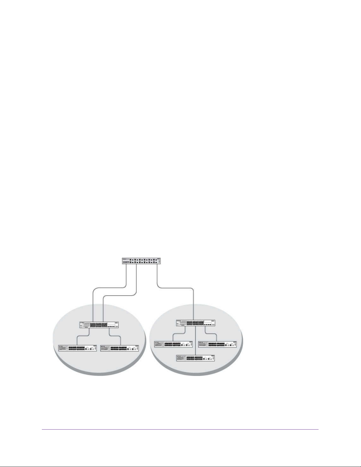
The Private Edge VLAN feature lets you set protection between ports located on the switch.
This means that a protected port cannot forward traf
switch. The feature does not provide protection between ports located on dif
fic to another protected port on the same
ferent switches.
fic for
The diagram in this section shows a switch with four ports configured to handle the traffic for
two VLANs. Port 1/0/2 handles traffic for both VLANs, while port 1/0/1 is a member of VLAN
2 only, and ports 1/0/3 and 1/0/4 are members of VLAN 3 only
. The script following the
diagram shows the commands you would use to configure the switch as shown in the
diagram.
Layer 3 switch
Port 1/0/2 VLAN
Router Port 1/3/1
192.150.3.1
Port 1/0/1
Layer 2
Switch
VLAN 10 VLAN 20
Port 1/0/3 VLAN
Router Port 1/3/2
192.150.4.1
Layer 2
Switch
Figure 1. Switch with 4 ports configured for traffic from 2 VLANs
The following examples show how to create VLANs, assign ports to the VLANs, and assign a
VLAN as the default VLAN to a port.
VLANs
21
Page 22
Managed Switches
Create Two VLANs
The example is shown as CLI commands and as a web interface procedure.
CLI: Create Two VLANs
Use the following commands to create two VLANs and to assign the VLAN IDs while leaving
the names blank.
(Netgear Switch) #vlan database
(Netgear Switch) (Vlan)#vlan 2
(Netgear Switch) (Vlan)#vlan 3
(Netgear Switch) (Vlan)#exit
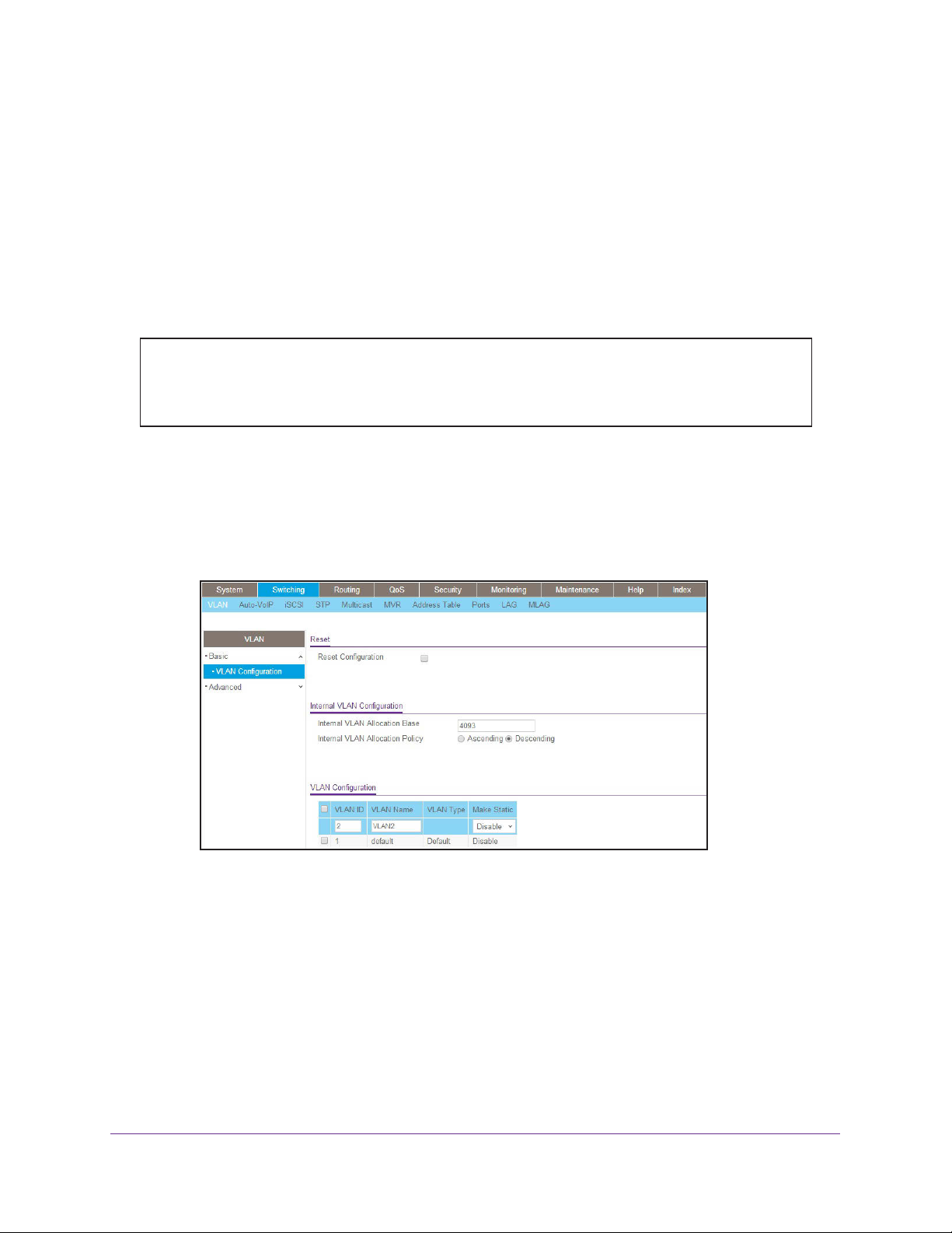
Web Interface: Create Two VLANs
1. Create VLAN2.
a. Select Switching > VLAN > Basic > VLAN Configuration.
A screen similar to the following displays.
b. Enter the following information:
• In the VLAN ID field, enter 2.
• In the VLAN Name field, enter VLAN2.
• In the VLAN Type list, select
Static.
c. Click Add.
2. Create VLAN3.
a. Select Switching > VLAN > Basic > VLAN Configuration.
VLANs
22
Page 23
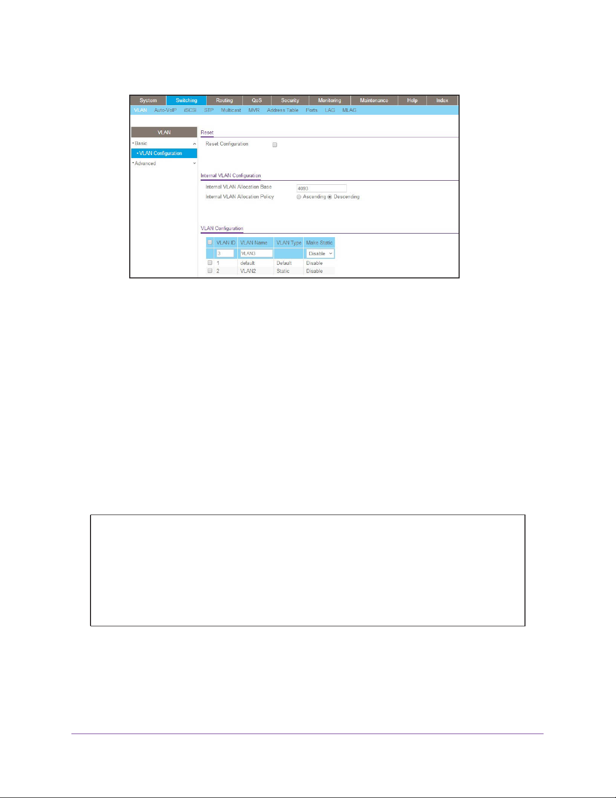
Managed Switches
A screen similar to the following displays.
b. Enter the following information:
• In the VLAN ID field, enter 3.
• In the VLAN Name field, enter VLAN3.
• In the VLAN Type list, select
Static.
c. Click Add.
Assign Ports to VLAN 2
This sequence shows how to assign ports to VLAN2, and to specify that frames will always
be transmitted tagged from all member ports and that untagged frames will be rejected on
receipt.
CLI: Assign Ports to VLAN 2
(Netgear Switch) #config
(Netgear Switch) (Config)#interface range 1/0/1-1/0/2
(Netgear Switch) (conf-if-range-1/0/1-1/0/2)#vlan participation include 2
(Netgear Switch) (conf-if-range-1/0/1-1/0/2)#vlan acceptframe vlanonly
(Netgear Switch) (conf-if-range-1/0/1-1/0/2)#vlan pvid 2
(Netgear Switch) (conf-if-range-1/0/1-1/0/2)#exit
(Netgear Switch) (Config)#vlan port tagging all 2
(Netgear Switch) (Config)#
VLANs
23
Page 24

Managed Switches
Web Interface: Assign Ports to VLAN 2
1. Assign ports to VLAN2.
a. Select Switching > VLAN > Advanced > VLAN Membership.
A screen similar to the following displays.
b. In the VLAN ID list, select 2.
c. Click Unit 1. The ports display.
d. Click the gray boxes under ports 1 and
2 until T displays.
The T specifies that the egress packet is tagged for the ports.
e. Click Apply to save the settings.
2. Specify that only tagged frames will be accepted on ports 1/0/1 and 1/0/2.
a. Select Switching > VLAN >
A screen similar to the following displays.
b. Under PVID Configuration, scroll down and select the check box for Interface 1/0/1.
Advanced > Port PVID Configuration.
Then scroll down and select the Interface 1/0/2 check box.
VLANs
24
Page 25
Managed Switches
c. Enter the following information:
• In the Acceptable Frame Type polyhedron list, select VLAN Only.
• In the
d. Click Apply to save the settings.
PVID (1 to 4093) field, enter 2.
Create Three VLANs
The example is shown as CLI commands and as a web interface procedure.
CLI: Create Three VLANs
Use the following commands to create three VLANs and to assign the VLAN IDs while
leaving the names blank.
(Netgear Switch) #vlan database
(Netgear Switch) (Vlan)#vlan 100
(Netgear Switch) (Vlan)#vlan 101
(Netgear Switch) (Vlan)#vlan 102
(Netgear Switch) (Vlan)#exit
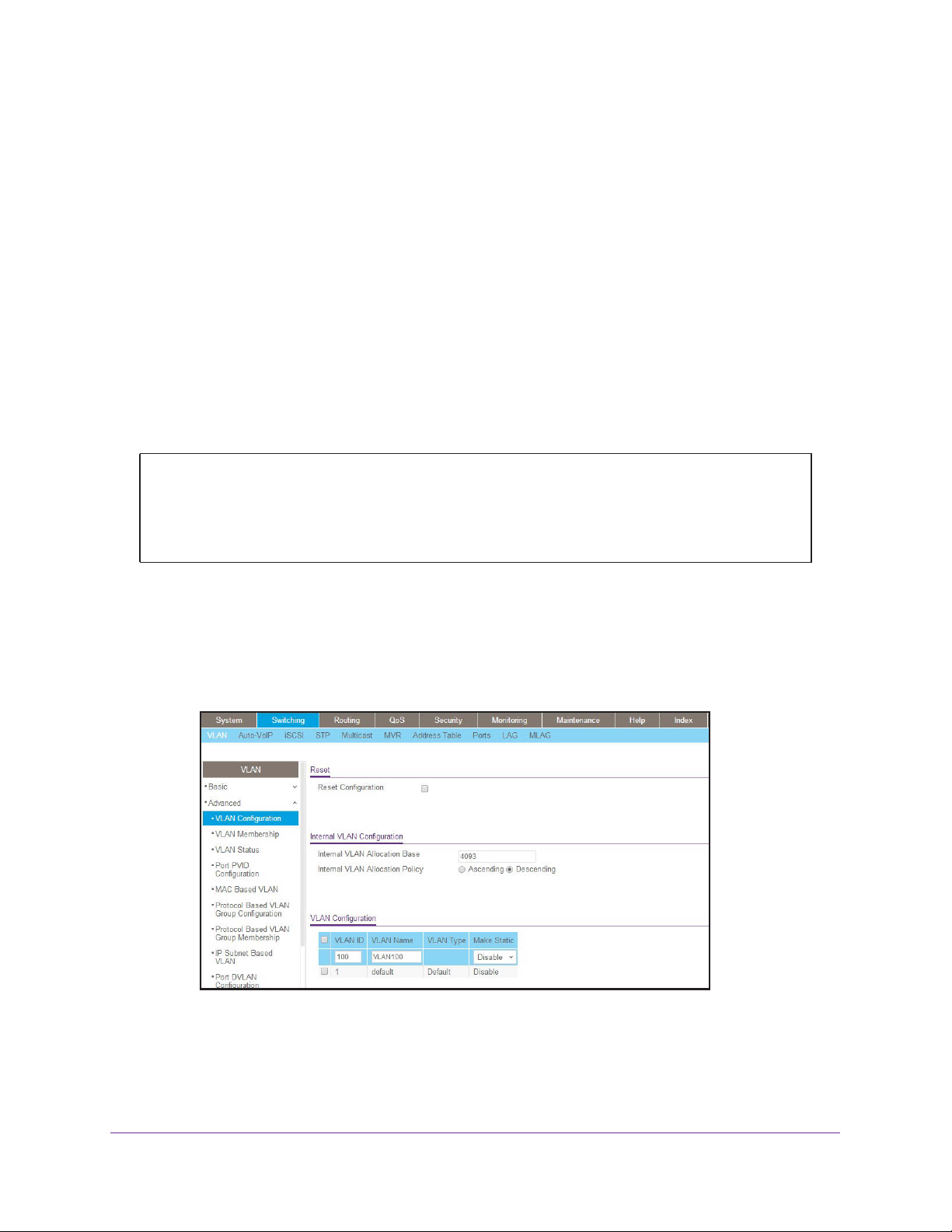
Web Interface: Create Three VLANs
1. Create VLAN100.
a. Select Switching > VLAN > Basic > VLAN Configuration.
A screen similar to the following displays.
b. Enter the following information:
• In the VLAN ID field, enter 100.
• In the VLAN Name field, enter VLAN100.
c. Click Add.
VLANs
25
Page 26
Managed Switches
2. Create VLAN101.
a. Select Switching > VLAN > Basic > VLAN Configuration.
A screen similar to the following displays.
b. Enter the following information:
• In the VLAN ID field, enter 101.
• In the VLAN Name field, enter VLAN101.
c. Click Add.
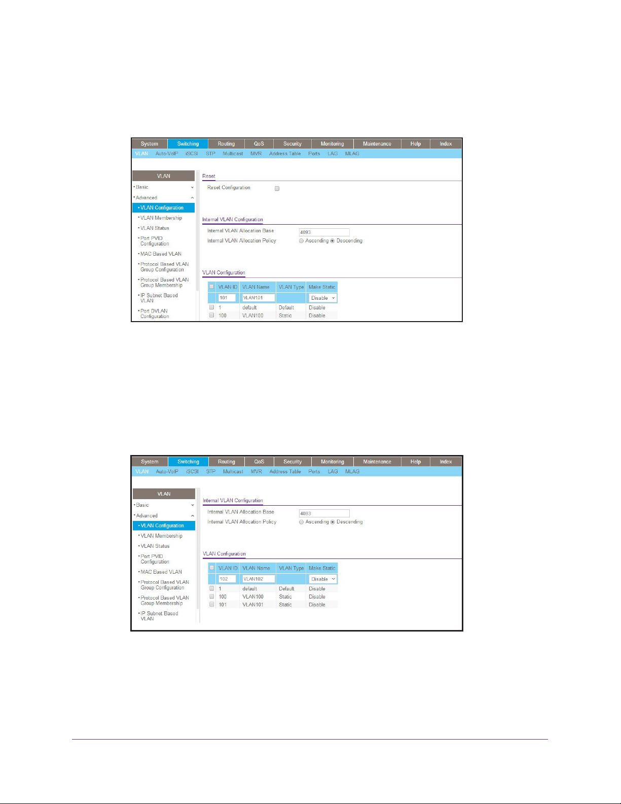
3. Create VLAN102.
a. Select Switching > VLAN > Basic > VLAN Configuration.
A screen similar to the following displays.
b. Enter the following information:
• In the VLAN ID field, enter 102.
• In the VLAN Name field, enter VLAN102.
c. Click Add.
VLANs
26
Page 27
Managed Switches
Assign Ports to VLAN 3
This example shows how to assign the ports that will belong to VLAN 3, and to specify that
untagged frames will be accepted on port 1/0/4. Note that port 1/0/2 belongs to both VLANs
and that port 1/0/1 can never belong to VLAN 3.
CLI: Assign Ports to VLAN 3
(Netgear Switch) (Config)#interface range 1/0/2-1/0/4
(Netgear Switch) (conf-if-range-1/0/2-1/0/4)#vlan participation include 3
(Netgear Switch) (conf-if-range-1/0/2-1/0/4)#exit
(Netgear Switch) (Config)#interface 1/0/4
(Netgear Switch) (Interface 1/0/4)#vlan acceptframe all
(Netgear Switch) (Interface 1/0/4)#exit
(Netgear Switch) (Config)#exit
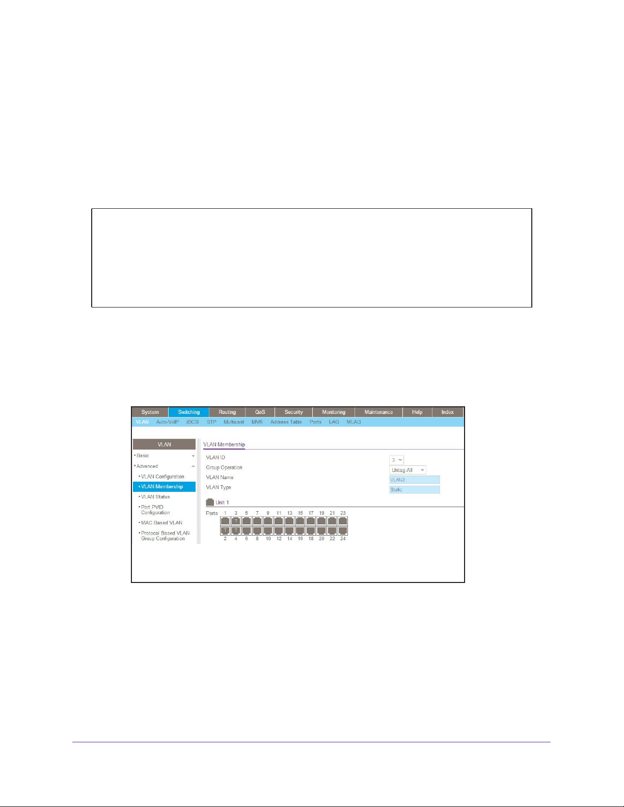
Web Interface: Assign Ports to VLAN 3
1. Assign ports to VLAN3.
a. Select Switching > VLAN > Advanced > VLAN Membership.
A screen similar to the following displays.
b. In the VLAN ID list, select 3.
c. Click Unit 1. The ports display.
d. Click the gray boxes under ports 2, 3, and 4 until T displays.
The
T specifies that the egress packet is tagged for the ports.
e. Click Apply
to save the settings.
2. Specify that untagged frames will be accepted on port 1/0/4.
a. Select Switching > VLAN >
Advanced > Port PVID Configuration.
VLANs
27
Page 28
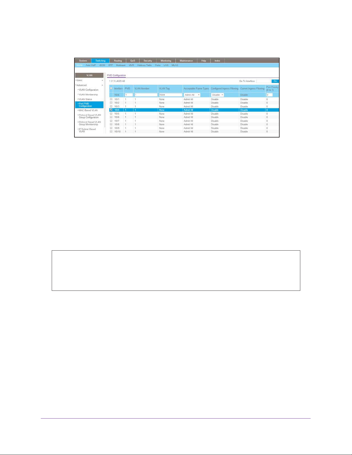
Managed Switches
A screen similar to the following displays.
b. Scroll down and select the Interface 1/0/4 check box.
Now 1/0/4 appears in the Interface field at the top.
c. In the Acceptable Frame Types list, select Admit All.
d. Click Apply
to save the settings.
Assign VLAN 3 as the Default VLAN for Port 1/0/2
This example shows how to assign VLAN 3 as the default VLAN for port 1/0/2.
CLI: Assign VLAN 3 as the Default VLAN for Port 1/0/2
(Netgear Switch) #config
(Netgear Switch) (Config)#interface 1/0/2
(Netgear Switch) (Interface 1/0/2)#vlan pvid 3
(Netgear Switch) (Interface 1/0/2)#exit
(Netgear Switch) (Config)#exit
VLANs
28
Page 29

Managed Switches
Web Interface: Assign VLAN 3 as the Default VLAN for Port 1/0/2
1. Select Switching > VLAN > Advanced > Port PVID Configuration.
A screen similar to the following displays.
2. Under PVID Configuration, scroll down and select the Interface 1/0/2 check box. Now 1/0/2
appears in the Interface field at the top.
3. In the PVID (1 to 4093) field, enter 3.
4. Click Apply to save the settings.
Create a MAC-Based VLAN
The MAC-based VLAN feature allows incoming untagged packets to be assigned to a VLAN
and thus classify traffic based on the source MAC address of the packet.
You define a MAC to VLAN mapping by configuring an entry in the MAC to VLAN table. An
entry is specified using a source MAC address and the appropriate VLAN ID. The MAC to
VLAN configurations are shared across all ports of the device (i.e., there is a system-wide
table that has MAC address to VLAN ID mappings).
When untagged or priority tagged packets arrive at the switch and entries exist in the MAC to
VLAN table, the source MAC address of the packet is looked up. If an entry is found, the
corresponding VLAN ID is assigned to the packet. If the packet is already priority tagged it
will maintain this value; otherwise, the priority will be set to 0 (zero).
verified against the VLAN table. If the VLAN is valid, ingress processing on the packet
continues; otherwise, the packet is dropped. This implies that you can configure a MAC
address mapping to a VLAN that has not been created on the system.
The assigned VLAN ID is
VLANs
29
Page 30

Managed Switches
CLI: Create a MAC-Based VLAN
1. Create VLAN3
(Netgear Switch)#vlan database
(Netgear Switch)(Vlan)#vlan 3
(Netgear Switch)(Vlan)#exit
.
2. Add port 1/0/23 to VLAN3.
(Netgear Switch)#config
(Netgear Switch)(Config)#interface 1/0/23
(Netgear Switch)(Interface 1/0/23)#vlan participation include 3
(Netgear Switch)(Interface 1/0/23)#vlan pvid 3
(Netgear Switch)(Interface 1/0/23)#exit
3. Map MAC 00:00:0A:00:00:02 to VLAN3.
(Netgear Switch)(Config)#exit
(Netgear Switch)#vlan data
(Netgear Switch)(Vlan)#vlan association mac 00:00:00A:00:00:02 3
(Netgear Switch)(Vlan)#exit
4. Add all the ports to VLAN3.
(Netgear Switch)#config
(Netgear Switch)(Config)#interface range 1/0/1-1/0/28
(Netgear Switch)(conf-if-range-1/0/1-1/0/28)#vlan participation include 3
(Netgear Switch)(conf-if-range-1/0/1-1/0/28)#exit
(Netgear Switch)(Config)#exit
VLANs
30
Page 31

Managed Switches
Web Interface: Assign a MAC-Based VLAN
1. Create VLAN3.
a. Select Switching > VLAN > Basic > VLAN Configuration.
A screen similar to the following displays.
b. Enter the following information:
• In the VLAN ID field, enter 3.
• In the VLAN Name field, enter VLAN3.
• In the VLAN Type list, select
c. Click Add.
2. Assign ports to VLAN3.
a. Select Switching > VLAN >
A screen similar to the following displays.
Static.
Advanced > VLAN Membership.
b. In the VLAN ID list, select 3.
c. Click Unit 1. The ports display.
VLANs
31
Page 32

Managed Switches
d. Click the gray box before Unit 1 until U displays.
e. Click Apply.
3. Assign
VPID3 to
port 1/0/23.
a. Select Switching > VLAN > Advanced > Port PVID Configuration.
A screen similar to the following displays.
b. Scroll down and select the 1/0/23 check box.
c. In the PVID (1 to 4093) field, enter 3.
d. Click Apply to save the settings.
4. Map the specific MAC to VLAN3.
a. Select Switching > VLAN >
Advanced > MAC based VLAN.
A screen similar to the following displays.
b. Enter the following information:
• In the MAC Address field, enter 00:00:0A:00:00:02.
• In the PVID (1 to 4093) field, enter 3.
c. Click Add.
VLANs
32
Page 33

Managed Switches
Create a Protocol-Based VLAN
Create two protocol VLAN groups. One is for IPX and the other is for IP/ARP. The untagged
IPX packets are assigned to VLAN 4, and the untagged IP/ARP packets are assigned to
VLAN 5.
CLI: Create a Protocol-Based VLAN
1. Create a VLAN protocol group vlan_ipx based on IPX protocol.
(Netgear Switch)#config
(Netgear Switch)(Config)#vlan protocol group 1
(Netgear Switch)(Config)#vlan protocol group name 1 "vlan_ipx"
(Netgear Switch)(Config)#vlan protocol group add protocol 1 ethertype ipx
2. Create a VLAN protocol group vlan_ipx based on IP/ARP protocol.
(Netgear Switch)(Config)#vlan protocol group 2
(Netgear Switch)(Config)#vlan protocol group name 2 "vlan_ip"
(Netgear Switch)(Config)#vlan protocol group add protocol 2 ethertype ip
(Netgear Switch)(Config)#vlan protocol group add protocol 2 ethertype arp
(Netgear Switch)(Config)#exit
3. Assign VLAN protocol group 1 to VLAN 4.
(Netgear Switch)#vlan database
(Netgear Switch)(Vlan)#vlan 4
(Netgear Switch)(Vlan)#vlan 5
(Netgear Switch)(Vlan)#protocol group 1 4
4. Assign VLAN protocol group 2 to VLAN 5.
(Netgear Switch)(Vlan)#protocol group 2 5
5. Enable protocol VLAN group 1 and 2 on the interface.
(Netgear Switch)(Vlan)#exit
(Netgear Switch)#config
(Netgear Switch)(Config)#interface 1/0/11
(Netgear Switch)(Interface 1/0/11)#protocol vlan group 1
(Netgear Switch)(Interface 1/0/11)#protocol vlan group 2
(Netgear Switch)(Interface 1/0/11)#exit
VLANs
33
Page 34

Managed Switches
Web Interface: Create a Protocol-Based VLAN
1. Create VLAN4 and VLAN5.
Create VLAN4.
a. Select Switching > VLAN > Basic > VLAN Configuration.
A screen similar to the following displays.
b. Enter the following information:
In the VLAN ID field, enter 4.
In the VLAN Name field, enter VLAN4.
In the VLAN T
c. Click Add.
Create VLAN5.
a. Select Switching > VLAN > Basic > VLAN Configuration.
A screen similar to the following displays.
ype list, select
Static.
VLANs
34
Page 35

Managed Switches
b. Enter the following information:
In the VLAN ID field, enter 5.
In the VLAN Name field, enter VLAN5.
In the VLAN T
ype list, select
Static.
c. Click Add.
2. Create the protocol-based VLAN group vlan_ipx.
a. Select Switching > VLAN >
Advanced > Protocol Based VLAN Group
Configuration.
A screen similar to the following displays.
Enter the following information:
• In the Group ID field, enter 1.
• In the Group Name field, enter vlan_ipx.
• In the Protocol list, enter ipx.
• In the VLAN ID field, enter 4.
b. Click Add.
3. Create the protocol-based VLAN group vlan_ip.
a. Select Switching > VLAN >Advanced > Protocol Based VLAN Group
Configuration.
VLANs
35
Page 36

Managed Switches
A screen similar to the following displays.
b. Enter the following information:
• In the Group ID field, enter 2.
• In the Group Name field, enter vlan_ip.
• In the Protocol list, select IP and ARP while holding down the Ctrl key.
• In the VLAN
field, enter 5.
c. Click Add.
4. Add port 1
1 to the group vlan_ipx.
a. Select Switching > VLAN > Advanced > Protocol Based VLAN Group
Membership.
A screen similar to the following displays.
b. In the Group ID list, select 1.
c. Click the gray box under port 11. A check mark displays in the box.
d. Click the Apply button.
VLANs
36
Page 37

Managed Switches
5. Add port 11 to the group vlan_ip.
a. Select Switching > VLAN > Advanced > Protocol Based VLAN Group
Membership.
A screen similar to the following displays.
b. In the Group ID list, select 2.
c. Click the gray box under port 11. A check mark displays in the box.
d. Click Apply.
Virtual VLANs: Create an IP Subnet–Based VLAN
In an IP subnet–based VLAN, all the end workstations in an IP subnet are assigned to the
same VLAN. In this VLAN, users can move their workstations without reconfiguring their
network addresses. IP subnet VLANs are based on Layer 3 information from packet headers.
The switch makes use of the network-layer address (for example, the subnet address for
TCP/IP networks) in determining VLAN membership. If a packet is untagged or priority
tagged, the switch associates the packet with any matching IP subnet classification. If no IP
subnet classification can be made, the packet is subjected to the normal VLAN classification
rules of the switch. This IP subnet capability does not imply a routing function or that the
VLAN is routed. The IP subnet classification feature affects only the VLAN assignment of a
packet. Appropriate 802.1Q VLAN configuration must exist in order for the packet to be
switched.
VLANs
37
Page 38

Managed Switches
1/0/24
PC 2
10.100.5.30
PC 1
10.100.5.1
1/0/1
Switch
Figure 2. IP subnet–based VLAN
CLI: Create an IP Subnet–Based VLAN
(Netgear Switch) #vlan database
(Netgear Switch) (Vlan)#vlan 2000
(Netgear Switch) (Vlan)#vlan association subnet 10.100.0.0 255.255.0.0 2000
(Netgear Switch) (Vlan)#exit
Create an IP subnet–based VLAN 2000.
(Netgear Switch) #config
(Netgear Switch) (Config)#interface range 1/0/1-1/0/24
(Netgear Switch) (conf-if-range-1/0/1-1/0/24)# vlan participation include 2000
(Netgear Switch) (conf-if-range-1/0/1-1/0/24)#exit
(Netgear Switch) (Config)#
Assign all the ports to VLAN 2000.
(Netgear Switch) #show mac-addr-table vlan 2000
MAC Address Interface Status
----------------- --------- -----------00:00:24:58:F5:56 1/0/1 Learned
00:00:24:59:00:62 1/0/24 Learned
VLANs
38
Page 39

Managed Switches
Web Interface: Create an IP Subnet–Based VLAN
1. Create VLAN 2000.
a. Select Switching > VLAN > Basic > VLAN Configuration.
A screen similar to the following displays.
b. Enter the following information:
• In the VLAN ID field, enter 2000.
• In the VLAN Type list, select Static.
c. Click Add.
2. Assign all the ports to VLAN 2000.
a. Select Switching > VLAN >
A screen similar to the following displays.
Advanced > VLAN Membership.
b. In the VLAN ID list, select 2000.
c. Click Unit 1. The ports display.
d. Click the gray box before Unit 1 until U
VLANs
39
displays.
Page 40

Managed Switches
e. Click Apply.
3. Associate the IP subnet with VLAN 2000.
a. Select Switching > VLAN >
A screen similar to the following displays.
Advanced > IP Subnet Based VLAN.
b. Enter the following information:
• In the IP Address field, enter 10.100.0.0.
• In the Subnet Mask field, enter 255.255.0.0.
• In the VLAN (1 to 4093) field, enter 2000.
c. Click Add.
Voice VLANs
The voice VLAN feature enables switch ports to carry voice traffic with defined priority to
enable separation of voice and data traffic coming onto port. Voice VLAN ensures that the
sound quality of an IP phone does not deteriorate when the data traffic on the port is high.
Also, the inherent isolation provided by VLANs ensures that inter-VLAN traffic is under
management control and that clients attached to the network cannot initiate a direct attack on
voice components.
Note: For more information about voice VLANs, seeAuto VoIP on page 305.
VLANs
40
Page 41

PBX
Managed Switches
1/0/1
GSM73xxS
1/0/2
VoIP
phone
PC
1/0/3
VoIP
phone
PC
Voice traffic
Data traffic
Figure 3. Voice VLAN
The script in this section shows how to configure Voice VLAN and prioritize the voice traffic.
Here the Voice VLAN mode is in VLAN ID 10.
CLI: Configure Voice VLAN and Prioritize Voice Traffic
1. Create VLAN 10.
(Netgear Switch) #vlan database
(Netgear Switch) (Vlan)#vlan 10
(Netgear Switch) (Vlan)#exit
VLANs
41
Page 42

Managed Switches
2. Include the ports 1/0/1 and 1/0/2 in VLAN 10.
(Netgear Switch) (Config)#interface range 1/0/1-1/0/2
(Netgear Switch) (conf-if-range-1/0/1-1/0/2)#vlan participation include 10
(Netgear Switch) (conf-if-range-1/0/1-1/0/2)#vlan tagging 10
(Netgear Switch) (conf-if-range-1/0/1-1/0/2)#exit
3. Configure Voice VLAN globally.
(Netgear Switch) (Config)# voice vlan
4. Configure Voice VLAN mode in the interface 1/0/2.
(Netgear Switch) (Config)#interface 1/0/2
(Netgear Switch) (Interface 1/0/2)#voice vlan 10
(Netgear Switch) (Interface 1/0/2)#exit
5. Create the DiffServ class ClassVoiceVLAN.
(Netgear Switch) (Config)#class-map match-all ClassVoiceVLAN
6. Configure VLAN 10 as the matching criteria for the class.
(Netgear Switch) (Config-classmap)#match vlan 10
7. Create the DiffServ policy PolicyVoiceVLAN.
(Netgear Switch) (Config)#policy-map PolicyVoiceVLAN in
8. Map the policy and class and assign them to the higher-priority queue.
(Netgear Switch) (Config-policy-map)#class ClassVoiceVLAN
(Netgear Switch) (Config-policy-classmap)#assign-queue 3
(Netgear Switch) (Config-policy-classmap)#exit
9. Assign it to interfaces 1/0/1 and 1/0/2.
(Netgear Switch) (Config)#interface range 1/0/1-1/0/2
(Netgear Switch) (conf-if-range-1/0/1-1/0/2)# service-policy in PolicyVoiceVLAN
VLANs
42
Page 43

Managed Switches
Web Interface: Configure Voice VLAN and Prioritize Voice Traffic
1. Create VLAN 10.
a. Select Switching > VLAN > Basic > VLAN Configuration.
A screen similar to the following displays.
b. In the VLAN ID field, enter 10.
c. In the VLAN Name field, enter Voice VLAN.
d. Click Add.
2. Include the ports 1/0/1 and 1/0/2 in VLAN 10.
a. Select
A screen similar to the following displays.
b. In the VLAN Membership table, in the VLAN ID list, select 10.
c. Select Port 1 and Port 2 as tagged.
d. Click Apply.
Switching > VLAN >
Advanced > VLAN Membership.
VLANs
43
Page 44

Managed Switches
3. Configure Voice VLAN globally.
a. Select Switching > VLAN > Advanced > Voice VLAN Configuration.
A screen similar to the following displays.
b. For Admin Mode, select the Enable radio button.
c. Click Apply.
4. Configure V
oice VLAN mode in the interface 1/0/2.
a. Select Switching > VLAN > Advanced > Voice VLAN Configuration.
b. Select the
1/0/2 check box.
c. In the Interface Mode list, select VLAN ID.
d. In the V
alue field, enter
10.
A screen similar to the following displays.
e. Click Apply.
VLANs
44
Page 45

Managed Switches
5. Create the DiffServ class ClassVoiceVLAN.
a. Select QoS > Advanced > DiffServ > Class Configuration.
A screen similar to the following displays.
b. In the Class Name field, enter ClassVoiceVLAN.
c. In the Class Type list, select All.
d. Click Add
. The Class Name screen displays, as shown in the next step in this
procedure.
6. Configure matching criteria for the class as VLAN 10.
a. Select
QoS > DiffServ > Advanced > Class Configuration.
A screen similar to the following displays.
b. Click the class ClassVoiceVLAN.
c. In the DiffServ Class Configuration table, select VLAN.
d. In the VLAN ID field, enter 10.
VLANs
45
Page 46

Managed Switches
A screen similar to the following displays.
e. Click Apply.
7. Create the DiffServ policy PolicyVoiceVLAN.
a. Select
QoS > DiffServ > Advanced > Policy Configuration.
A screen similar to the following displays.
b. In the Policy Name field, enter PolicyVoiceVLAN.
c. In the Policy Type list, select In.
d. In the
e. Click Add
Member Class list, select ClassVoiceVLAN.
.
The Policy Configuration screen displays, as shown in the next step in this procedure.
8. Map the policy and class and assign them to the higher-priority queue.
a. Select QoS > DiffServ >
Advanced > Policy Configuration.
VLANs
46
Page 47

Managed Switches
A screen similar to the following displays.
b. Click the Policy PolicyVoiceVLAN.
A screen similar to the following displays.
c. In the field next to the Assign Queue radio button, select 3.
d. Click Apply.
9. Assign it to interfaces 1/0/1 and 1/0/2.
a. Select QoS > DiffServ >
Advanced > Service Interface Configuration.
VLANs
47
Page 48

Managed Switches
A screen similar to the following displays.
b. Select the check boxes for Interfaces 1/0/1 and 1/0/2.
c. Set the Policy Name field as PolicyVoiceVLAN.
d. Click Apply.
Configure GARP VLAN Registration Protocol
Generic Attribute Registration Protocol (GARP) VLAN Registration Protocol (GVRP) provides
IEEE 802.1Q-compliant VLAN pruning and dynamic VLAN creation on 802.1Q-tagged ports.
With GVRP, a switch can exchange VLAN configuration information with other GVRP
switches, prune unnecessary broadcast and unknown unicast traffic, and create and manage
VLANs dynamically on switches that are connected through 802.1Q-tagged ports.
1/0/24 Tagged
1/0/11
GVRP Switch A
Figure 4. GVRP configuration
GVRP Switch B
VLANs
48
Page 49

Managed Switches
CLI: Enable GVRP
1. On Switch A, create VLANs 1000, 2000, and 3000, and add port 1/0/24 as a tagged port
to VLANs 1000, 2000, and 3000.
(Netgear Switch) #vlan database
(Netgear Switch) (Vlan)#vlan 1000,2000,3000
(Netgear Switch) (Vlan)#exit
(Netgear Switch) #config
(Netgear Switch) (Config)#interface 1/0/24
(Netgear Switch) (Interface 1/0/24)#vlan participation include 1000
(Netgear Switch) (Interface 1/0/24)#vlan participation include 2000
(Netgear Switch) (Interface 1/0/24)#vlan participation include 3000
(Netgear Switch) (Interface 1/0/24)#vlan tagging 1000,2000,3000
2. On Switch A, enable GVRP.
(Netgear Switch) #set gvrp adminmode
(Netgear Switch) #config
(Netgear Switch) (Config)#interface 1/0/24
(Netgear Switch) (Interface 1/0/24)#set gvrp interfacemode
3. On Switch B, enable GVRP.
(Netgear Switch) #set gvrp adminmode
(Netgear Switch) #config
(Netgear Switch) (Config)#interface 1/0/11
(Netgear Switch) (Interface 1/0/11)#set gvrp interfacemode
VLANs
49
Page 50

Managed Switches
4. On Switch B, verify that VLANs 1000, 2000, and 3000 were created.
(Netgear Switch) #show vlan
Maximum VLAN Entries........................... 1024
VLAN Entries Currently in Use.................. 5
VLAN ID VLAN Name VLAN Type
------- -------------------------------- ------------------1 default Default
2 Auto VoIP AUTO VoIP
1000 Dynamic (GVRP)
2000 Dynamic (GVRP)
3000 Dynamic (GVRP)
(Netgear Switch) #show vlan 1000
VLAN ID: 1000
VLAN Name:
VLAN Type: Dynamic (GVRP)
Interface Current Configured Tagging
---------- -------- ----------- -------1/0/1 Exclude Autodetect Untagged
1/0/2 Exclude Autodetect Untagged
1/0/3 Exclude Autodetect Untagged
1/0/4 Exclude Autodetect Untagged
1/0/5 Exclude Autodetect Untagged
1/0/6 Exclude Autodetect Untagged
1/0/7 Exclude Autodetect Untagged
1/0/8 Exclude Autodetect Untagged
1/0/9 Exclude Autodetect Untagged
1/0/10 Exclude Autodetect Untagged
1/0/11 Include Autodetect Tagged
1/0/12 Exclude Autodetect Untagged
1/0/13 Exclude Autodetect Untagged
1/0/14 Exclude Autodetect Untagged
1/0/15 Exclude Autodetect Untagged
1/0/16 Exclude Autodetect Untagged
VLANs
50
Page 51

Managed Switches
Web Interface: Configure GVRP on switch A
1. On Switch A, create VLANs 1000, 2000, and 3000:
a. Select Switching > VLAN > Advanced > VLAN Configuration.
A screen similar to the following displays.
b. In the VLAN ID field, enter 1000.
c. Click Add.
d. Repeat Step a through Step c to create VLANs 2000 and 3000.
2. Add port 1/0/24 as a tagged port to VLANs 1000, 2000, and 3000:
a. Select Switching > VLAN >
A screen similar to the following displays.
a. From the VLAN ID menu, select 1000.
b. Click Unit 1.
Advanced > VLAN Membership.
The ports display.
c. Click the gray box under port 24 until T displays.
VLANs
51
Page 52

T specifies that the switch tags egress packets for port 24.
d. Click Apply.
3. Enable GVRP globally:
a. Select Switching > VLAN >
A screen similar to the following displays.
Managed Switches
Advanced > GARP Switch Configuration.
b. Next to GVRP Mode, select the Enable radio button.
c. Click Apply.
4. Enable GVRP on port 1/0/24.
a. Select Switching > VLAN >
Advanced > GARP Port Configuration.
A screen similar to the following displays.
b. Scroll down and select the check box that corresponds to interface 1/0/24.
The Interface field in the table heading displays 1/0/24.
VLANs
52
Page 53

Managed Switches
c. From the Port GVRP Mode menu, select Enable.
d. Click Apply.
Web Interface: Configure GVRP on Switch B
1. Enable GVRP globally:
a. Select Switching > VLAN > Advanced > GARP Switch Configuration.
A screen similar to the following displays.
b. Next to GVRP Mode, select the Enable radio button.
c. Click Apply.
2. Enable GVRP on port 1/0/1
a. Select Switching > VLAN > Advanced > GARP Port Configuration.
A screen similar to the following displays.
1:
VLANs
53
Page 54

Managed Switches
b. Scroll down and select the check box that corresponds to interface 1/0/11.
The Interface field in the table heading displays 1/0/11.
c. From the Port GVRP Mode menu, select Enable.
d. Click Apply.
Private VLANs
The Private VLANs feature separates a regular VLAN domain into two or more subdomains.
Each subdomain is defined (represented) by a primary VLAN and a secondary VLAN. The
primary VLAN ID is the same for all subdomains that belong to a private VLAN. The
secondary VLAN ID differentiates subdomains from each other and provides Layer 2 isolation
between ports of the same private VLAN.
There are three types of VLAN within a private VLAN:
• Primary VLAN. it forwards the traffic from the promiscuous ports to isolated ports,
community ports, and other promiscuous ports in the same private VLAN. Only one
primary VLAN can be configured per private VLAN.
share the same primary VLAN.
• Community VLAN. is a secondary VLAN. It forwards traf
belong to the same community and to the promiscuous ports.
community VLANs per private VLAN.
• Isolated VLAN. is a secondary VLAN. It carries traffic from isolated ports to
promiscuous ports. Only one isolated VLAN can be configured per private VLAN.
All ports within a private VLAN
fic between ports which
There can be multiple
There are three types of port designation within a private VLAN:
• Promiscuous port
interfaces in the private VLAN, including other promiscuous ports, community ports,
and isolated ports.
• Community ports. These ports can communicate with other community ports and
promiscuous ports.
• Isolated ports
The following figure shows how private VLANs can be extended across multiple switches
through inter-switch/stack links that transport primary, community
between devices.
. belongs to a primary VLAN and can communicate with all
. These can ONL
Y communicate with promiscuous ports.
, and isolated VLANs
VLANs
54
Page 55

Managed Switches
Figure 5. Private VLANs
The following figure illustrates the private VLAN traffic flow . Five ports A, B, C, D, and E make
up a private VLAN. Port A is a promiscuous port which is associated with the primary VLAN
100. Ports B and C are the host ports which belong to the isolated VLAN 101. Ports D and E
are the community ports which are associated with community VLAN 102. Port F is the
inter-switch/stack link. It is configured to transmit VLANs 100, 101 and 102. Colored arrows
represent possible packet flow paths in the private VLAN domain.
Figure 6. Packet flow within a Private VLAN domain
VLANs
55
Page 56

Managed Switches
Assign Private-VLAN Types (Primary, Isolated, Community)
The example is shown as CLI commands and as a web interface procedure.
CLI: Assign Private-VLAN Type (Primary, Isolated, Community)
Use the following commands to assign VLAN 100 to primary VLAN, VLAN 101 to isolated
VLAN, and VLAN 102 to community VLAN.
(Netgear Switch) #config
(Netgear Switch) (Config)#vlan 100
(Netgear Switch) (Config)(Vlan) #private-vlan primary
(Netgear Switch) (Config)(Vlan) #exit
(Netgear Switch) (Config)#vlan 101
(Netgear Switch) (Config)(Vlan) #private-vlan isolated
(Netgear Switch) (Config)(Vlan) #exit
(Netgear Switch) (Config)#vlan 102
(Netgear Switch) (Config)(Vlan) #private-vlan community
(Netgear Switch) (Config)(Vlan) #end
Web Interface: Assign Private-VLAN Type (Primary, Isolated, Community)
1. Create VLAN 10.
a. Select Security > Traffic Control >
Configuration.
A screen similar to the following displays.
Private VLAN > Private VLAN Type
VLANs
56
Page 57

Managed Switches
b. Under Private VLAN Type Configuration, select the VLAN ID 100 check box. Now
100 appears in the interface field at the top.
c. In the Private VLAN Type field, select
Primary from the pull-down menu.
d. Click Apply to save the settings
2. Assign VLAN 101 as an isolated VLAN.
a. Select Security > T
raffic Control >
Private VLAN > Private VLAN Type
Configuration.
A screen similar to the following displays.
b. Under Private VLAN Type Configuration, select the VLAN ID 101 check box.
Now 101 appears in the interface field at the top.
c. In the Private VLAN Type field, select
Isolated from the pull-down menu.
d. Click Apply to save the settings
3. Assign VLAN 102 to community VLAN.
a. Select Security > T
raffic Control >
Private VLAN > Private VLAN Type
Configuration.
A screen similar to the following displays.
VLANs
57
Page 58

Managed Switches
b. Under Private VLAN Type Configuration, select the VLAN ID 102 check box. Now
102 appears in the interface field at the top.
c. In the Private VLAN Type field, select
d. Click Apply to save the settings.
Community from the pull-down menu.
Configure Private-VLAN Association
The example is shown as CLI commands and as a web interface procedure.
CLI: Configure Private-VLAN Association
Use the following commands to associate VLAN 101-102 (secondary VLAN) to VLAN 100
(primary VLAN).
(Netgear Switch) #config
(Netgear Switch) (Config)#vlan 100
(Netgear Switch) (Config)(Vlan) #private-vlan association 101-102
(Netgear Switch) (Config)(Vlan) #end
Web Interface: Configure Private-VLAN Association
1. Associate VLAN 101-102 (secondary VLAN) to VLAN 100 (primary VLAN).
a. Select Security > Traffic Control >
Configuration.
A screen similar to the following displays.
b. Under Private VLAN Association Configuration, select the VLAN ID 100.
c. In the Secondary VLAN(s) field, type 101-102.
d. Click Apply to save the settings.
Private VLAN > Private VLAN Association
VLANs
58
Page 59

Managed Switches
Configure Private-VLAN Port Mode (Promiscuous, Host)
The example is shown as CLI commands and as a web interface procedure.
CLI: Configure Private-VLAN Port Mode (Promiscuous, Host)
Use the following commands to assign port 1/0/1 to promiscuous port mode and ports
1/0/2-1/0/5 to host port mode.
(Netgear Switch) #config
(Netgear Switch) (Config)#interface 1/0/1
(Netgear Switch) (Interface 1/0/1)#switchport mode private-vlan promiscuous
(Netgear Switch) (Interface 1/0/1)#exit
(Netgear Switch) (Config)#interface 1/0/2-1/0/5
(Netgear Switch) (Interface 1/0/2-1/0/5)#switchport mode private-vlan host
(Netgear Switch) (Interface 1/0/2-1/0/5)#end
Web Interface: Configure Private-VLAN Port Mode (Promiscuous, Host)
1. Configure port 1/0/1 to promiscuous port mode.
a. Select Security > Traffic Control >
Configuration.
A screen similar to the following displays.
Private VLAN > Private VLAN Port Mode
b. Under Private VLAN Port Mode Configuration, select the 1/0/1 interface check
box.
Now 1/0/1 appears in the Interface field at the top.
c. In the Port VLAN Mode field, select Promiscuous from the pull-down menu.
VLANs
59
Page 60

Managed Switches
d. Click Apply to save the settings.
2. Configure ports 1/0/2-1/0/5 to host port mode.
a. Select Security > T
raffic Control >
Private VLAN > Private VLAN Port Mode
Configuration.
A screen similar to the following displays.
b. Under Private VLAN Port Mode Configuration, select the 1/0/2 to 1/0/5 interface
check box.
c. In the Port VLAN Mode field, select Host from the pull-down menu.
d. Click Apply to save the settings.
Configure Private-VLAN Host Ports
The example is shown as CLI commands and as a web interface procedure.
CLI: Configure Private-VLAN Host Ports
Use the following commands to associate isolated ports 1/0/2-1/0/3 to a private-VLAN
(primary=100, secondary=101). Community ports 1/0/4-1/0/5 to a private-VLAN (primary=
100, secondary=102).
(Netgear Switch) #config
(Netgear Switch) (Config)#interface 1/0/2-1/0/3
(Netgear Switch) (Interface 1/0/2-1/0/3)#switchport private-vlan host-association
100 101
(Netgear Switch) (Interface 1/0/2-1/0/3)#exit
(Netgear Switch) (Config)#interface 1/0/4-1/0/5
(Netgear Switch) (Interface 1/0/4-1/0/5)#switchport private-vlan host-association
100 102
(Netgear Switch) (Interface 1/0/4-1/0/5)#end
VLANs
60
Page 61

Managed Switches
Web Interface: Assign Private-VLAN Port Host Ports
1. Associate isolated ports 1/0/2-1/0/3 to a private-VLAN (primary=100, secondary=101).
a. Select Security > Traffic Control >
Configuration.
A screen similar to the following displays.
Private VLAN > Private VLAN Host Interface
b. Under Private VLAN Host Interface Configuration, select the 1/0/2 and 1/0/3
interface check box.
c. In the Host Primary VLAN field, enter 100.
d. In the Host Secondary VLAN field, enter 101.
e. Click Apply to save the settings.
2. Associate isolated ports 1/0/4-1/0/5 to a private-VLAN (primary=100, secondary=102).
a. Select Security > T
Configuration.
A screen similar to the following displays.
raffic Control >
Private VLAN > Private VLAN Host Interface
b. Under Private VLAN Host Interface Configuration, select the 1/0/4 and 1/0/5
interface check box.
VLANs
61
Page 62

Managed Switches
c. In the Host Primary VLAN field, enter 100.
d. In the Host Secondary VLAN field, enter 102.
e. Click Apply to save the settings.
Map Private-VLAN Promiscuous Port
The example is shown as CLI commands and as a web interface procedure.
CLI: Map Private-VLAN Promiscuous Port
Use the following commands to map private-VLAN promiscuous port 1/0/1 to a primary VLAN
(100) and to secondary VLANs (101-102).
(Netgear Switch) #config
(Netgear Switch) (Config)#interface 1/0/1
(Netgear Switch) (Interface 1/0/1)#switchport private-vlan mapping 100 101-102
(Netgear Switch) (Interface 1/0/1)#end
Web Interface: Map Private-VLAN Promiscuous Port
1. Map private-VLAN promiscuous port 1/0/1 to a primary VLAN (100) and to selected
secondary VLANs (101-102).
a. Select Security > Traffic Control >
Interface Configuration.
A screen similar to the following displays.
Private VLAN > Private VLAN Promiscuous
b. Under Private VLAN Promiscuous Interface Configuration, select the 1/0/1
interface check box. Now 1/0/1 appears in the Interface field at the top.
c. In the Promiscuous Primary VLAN field, enter 100.
VLANs
62
Page 63

Managed Switches
d. In the Promiscuous Secondary VLAN field, enter 101-102.
e. Click Apply to save the settings
VLAN Access Ports and Trunk Ports
Using switch ports can minimize potential configuration errors. Switch ports also facilitate the
configuration of a VLAN by reducing the number of commands that you must enter. To
configure a port that is connected to an end user, use a switch port in access mode. To
configure a port that is connected to another switch, use a switch port in trunk mode.
In addition, to access mode and trunk mode, you can configure switch ports in general mode,
which is the default mode and does not restrict the configuration so you can configure the
port as needed.
The switch supports the following switch port modes, each with its own VLAN membership
rules:
• Access mode. In access mode, the following rules apply to switch ports:
- Ports belong to a single VLAN, for which the VID is the configured PVID.
- Ports are intended for end-point connections, which, in general, do not operate with
LANs and operate with tagged traffic.
- Ports accept both tagged and untagged traffic. (Y
ports accepts tagged or untagged traffic.)
- All egress traffic must be sent untagged.
- Ingress filtering is always enabled.
- Ports are intended for connecting end stations to the switch, especially when end
stations are incapable of generating VLAN tags.
• T
runk mode. In trunk mode, the following rules apply to switch ports:
- Ports can belong to as many VLANs as needed.
- Ports accept both incoming tagged and untagged traf
- All incoming untagged frames are tagged with the native VLAN as the VID.
- Egress frames are sent tagged for all VLANs other than the native VLAN. Frames that
belong to the native VLAN are sent without a VLAN tag.
- Ingress filtering is always enabled. If incoming frames are tagged correctly (that is,
tagged with a VID of one of the VLANs to which the port belongs), they are admitted.
- Ports are intended for connections between switches, for which the traf
tagged.
- If you configure a list with allowed VLANs, a trunk port becomes a member of VLANs
that are defined in the list with allowed VLANs.
• General mode
- By default, all ports are designated as general mode ports and belong to the default
VLAN.
- Ports conform to NETGEAR legacy switch behavior for switch ports.
. In general mode, the following rules apply to switch ports:
ou cannot configurable whether the
fic.
fic is generally
VLANs
63
Page 64

Managed Switches
- You configure various VLAN parameters such as membership, tagging, and PVID by
using legacy commands.
- You can enable or disable ingress filtering.
The following figure shows a configuration with access ports and a trunk port.
PC1
PC2
Figure 7. Access and trunk ports
1/0/1 access port
in VLAN 1000
Switch
1/0/2 access port
in VLAN 2000
CLI: Configure a VLAN Trunk
1. Create VLAN 1000 and 2000.
(Netgear Switch) #vlan database
(Netgear Switch) (Vlan)#vlan 1000
(Netgear Switch) (Vlan)#vlan 2000
(Netgear Switch) (Vlan)#exit
1/0/3 trunk port
Network
that allows
LANs 1000 and 2000
2. Configure port 1/0/1 as an access port.
(Netgear Switch) #config
(Netgear Switch) (Config)#interface 1/0/1
(Netgear Switch) (Interface 1/0/1)#switchport mode access
(Netgear Switch) (Interface 1/0/1)#switchport access vlan 1000
(Netgear Switch) (Interface 1/0/1)#exit
(Netgear Switch) (Config)#
VLANs
64
Page 65

Managed Switches
3. Configure port 1/0/2 as an access port.
(Netgear Switch) #config
(Netgear Switch) (Config)#interface 1/0/2
(Netgear Switch) (Interface 1/0/2)#switchport mode access
(Netgear Switch) (Interface 1/0/2)#switchport access vlan 2000
(Netgear Switch) (Interface 1/0/2)#exit
(Netgear Switch) (Config)#
4. Configure port 1/0/3 as a trunk port.
(Netgear Switch) (Interface 1/0/3)#switchport mode trunk
(Netgear Switch) (Interface 1/0/3)#switchport trunk allowed vlan 1000,2000
5. Configure all incoming untagged packets to be tagged with the native VLAN ID.
(Netgear Switch) (Interface 1/0/3)#switchport trunk native vlan 1000
Web Interface: Configure a VLAN Trunk
1. Create VLAN 1000
a. Select Switching > VLAN > Advanced > VLAN Configuration.
A screen similar to the following displays.
b. In the VLAN ID field, enter 1000.
c. Click Add.
VLANs
65
Page 66

Managed Switches
a. Select Switching > VLAN > Advanced > VLAN Configuration.
A screen similar to the following displays.
b. In the VLAN ID field, enter 2000.
c. Click Add.
2. Configure port 1/0/1 as an access port in VLAN 1000.
a. Select Switching > VLAN > Advanced > VLAN Trunking Configuration.
A screen similar to the following displays.
VLANs
66
Page 67

Managed Switches
b. Select the check box that corresponds to interface 1/0/1.
The Interface field in the table heading displays 1/0/1.
c. In the Switchport Mode field, select Access.
d. In the Access VLAN ID field, select 1000.
e. Click Apply.
3. Configure port 1/0/2 as an access port in VLAN 2000.
a. Select Switching > VLAN > Advanced > VLAN Trunking Configuration.
A screen similar to the following displays.
b. Select the check box that corresponds to interface 1/0/2.
The Interface field in the table heading displays 1/0/2.
c. In the Switchport Mode field, select Access.
d. In the Access VLAN ID field, select 2000.
e. Click Apply.
4. Configure port 1/0/3 as a trunk port that allows VLANs 1000 and 2000.
a. Select Switching > VLAN > Advanced > VLAN Trunking Configuration.
A screen similar to the following displays.
VLANs
67
Page 68

Managed Switches
b. Select the check box that corresponds to interface 1/0/3.
The Interface field in the table heading displays 1/0/3.
c. In the Switchport Mode field, select Trunk.
d. In the
Native VLAN ID field, select 2000.
Note: In this step, you configure incoming untagged packets to be tagged
with VLAN ID 2000. If you want the switch to drop untagged packets,
ignore this step.
e. In the T
runk Allowed VLANs field, enter
1000,2000.
f. Click Apply.
VLANs
68
Page 69

3. LAGs
Link Aggregation Groups
This chapter includes the following sections:
• Link Aggregation Concepts
• Add Ports to LAGs
3
69
Page 70

Managed Switches
Link Aggregation Concepts
Link aggregation allows the switch to treat multiple physical links between two endpoints as a
single logical link. All the physical links in a given LAG must operate in full-duplex mode at the
same speed. LAGs can be used to directly connect two switches when the traffic between
them requires high bandwidth and reliability , or to provide a higher-bandwidth connection to a
public network. Management functions treat a LAG as if it is a single physical port. You can
include a LAG in a VLAN. You can configure more than one LAG for a given switch.
Port 1/0/3
Server
LAG_10
Port 1/0/2
LAG_10
Layer 3 Switch
Subnet 3
Port 1/0/8
LAG 20
Layer 2 Switch
Subnet 2 Subnet 3
Figure 8. Example network with two LAGs
Port 1/0/9
LAG_20
LAGs offer the following benefits:
• Increased reliability and availability. If one of the physical links in the LAG goes down,
traffic is dynamically and transparently reassigned to one of the other physical links.
• Better use of physical resources. Traf
fic can be load-balanced across the physical links.
• Increased bandwidth. The aggregated physical links deliver higher bandwidth than each
individual link.
• Incremental increase in bandwidth. A physical upgrade could produce a tenfold increase
in bandwidth; LAG produces a twofold or fivefold increase, which is useful if only a small
increase is needed.
LAGs
70
Page 71

Managed Switches
Add Ports to LAGs
The example is shown as CLI commands and as a web interface procedure.
CLI: Add Ports to the LAGs
(Netgear Switch) #config
(Netgear Switch) (Config)#interface 0/2
(Netgear Switch) (Interface 0/2)#addport 1/1
(Netgear Switch) (Interface 0/2)#exit
(Netgear Switch) (Config)#interface 0/3
(Netgear Switch) (Interface 0/3)#addport 1/1
(Netgear Switch) (Interface 0/3)#exit
(Netgear Switch) (Config)#interface 0/8
(Netgear Switch) (Interface 0/8)#addport 1/2
(Netgear Switch) (Interface 0/8)#exit
(Netgear Switch) (Config)#interface 0/9
(Netgear Switch) (Interface 0/9)#addport 1/2
(Netgear Switch) (Interface 0/9)#exit
(Netgear Switch) (Config)#exit
Web Interface: Add Ports to LAGs
1. Add ports to lag_10.
a. Select Switching > LAG > LAG Membership.
A screen similar to the following displays.
b. In the LAG ID list, select LAG 1.
c. Click Unit 1. The ports display.
d. Click the gray boxes under port 2 and 3
.
LAGs
71
Page 72

Managed Switches
Two check marks display in the box.
e. Click the Apply button to save the settings.
2. Add ports to lag_20.
a. Select Switching > LAG > LAG Membership.
A screen similar to the following displays.
b. Under LAG Membership, in the LAG ID list, select LAG 2.
c. Click Unit 1. The ports display.
d. Click the gray boxes under ports 8 and
9.
Two check marks display in the boxes.
e. Click Apply to save the settings.
LAGs
72
Page 73

4. MLAGs
Multichassis Link Aggregation Groups
This chapter includes the following sections:
• Multichassis Link Aggregation Concepts
• Create an MLAG
• Enable Static Routing on MLAG Interfaces
• Enable DCPDP on MLAG Interfaces
• Troubleshoot the MLAG Configuration
Note: MLAGs are available on the M6100 and M7100 series switches only.
4
73
Page 74

Managed Switches
Multichassis Link Aggregation Concepts
In a Layer 2 network, Spanning Tree Protocol (STP) is deployed to avoid network loops. With
STP running, ports can either be in forwarding or in blocked state. When a topology change
occurs, STP reconverges the network to a new stable loop-free network. STP is successful in
managing Layer 2 networks and mitigating loops in the network.
However, because STP marks ports as forwarding or blocking, a significant percentage of the
links in a network do not carry data traffic.
reconvergence of up to several seconds.
New loop management technologies include Spanning Tree Bridges and Transparent
Interconnection of Lots of Links (TRILL), and a multichassis LAG (MLAG) solution such as
Virtual Private Cloud (VPC).
o avoid using STP, you can bundle together multiple links between two adjacent switches
T
using a link aggregation group (LAG). The advantages of a LAG are that all member links are
in forwarding state and a link failure does not cause disruptions in the order of seconds (a
LAG handles a link failure in less than one second). However
typical LAG setting, the network can go down.
Also, any disruption in existing links causes a
, if a device failure occurs in a
A multichassis LAG (MLAG) carries the advantages of a LAG across multiple devices. An
MLAG enables links that are on two dif
The remote partner device does not detect that it is pairing with two dif
a LAG. The advantages of an MLAG are that all links can carry data traffic simultaneously,
and if a link or device failure occurs, the network can be resolved and the traffic can resume
quickly.
The following figure shows an example of an MLAG deployment topology.
ferent switches to pair with links on a partner device.
ferent devices to form
MLAGs
74
Page 75

Managed Switches
C
LAG 1
MLAG 3
(LAG 4)
P
P13
P11
MLAG 1
(LAG 2)
LAG 1
LAG 1(P21, P22, P23, P24)
P12
MLAG 2
(LAG 3)
LAG 1 (S21, S22, S23, S24)
Peer link
A
Figure 9. Example of an MLAG deployment topology
MLAG 3
(LAG 4)
MLAG 1
(LAG 2)
S13
LAG 1
B
S11
MLAG 2
(LAG 3)
S
S12
In the MLAG deployment topology example:
• P and S are MLAG-aware peer devices. P stands for primary device and S stands for
secondary device. The roles are elected after the devices exchanged keep-alive
messages. The primary device owns the MLAG member ports on the secondary device.
The primary device handles the control plane functionality of supported protocols for the
MLAG member ports on the secondary.
• The two devices are connected with a peer link.
The peer link must be configured on a
port-channel interface (that is, a LAG). Only one peer link is allowed per switch. All
instances of MLAG running on the two peer switches share this peer link.
The peer link is
used for the following purposes:
- Carry keep-alive messages to the peer
.
- Syncing forwarding database (FDB) entries that are learned on MLAG interfaces
between the two MLAG peer switches.
MLAGs
75
Page 76

Managed Switches
- STP Bridge Protocol Data Units (BPDUs) and Link Aggregation Control Protocol Data
Units (LACPDUs) that are received on secondary MLAG member ports are forwarded
to the primary MLAG component over the peer link.
- Interface events that are related to the MLAG interface and its member ports and that
occur on the secondary device are transferred over the peer link to the primary device
for handling.
- MLAG control information between the primary device and the secondary MLAG
switches is carried over the peer link.
- When all member ports of an MLAG interface are down on one MLAG switch, the
traffic that is received on that switch and that is destined for the MLAG is sent over the
peer link to the peer MLAG switch for forwarding.
The MLAG deployment topology example also includes the following ports and devices:
• P21, P22, P23, P24, S21, S22, S23, and S24 are the port-channel ports that form the
peer link.
• Ports P11, S1
1 are members of MLAG1 and ports P12, S12 are members of MLAG2.
• A, B, and C, are LAG devices.
• A and B are partner devices that form an MLAG with P and S. On
A and B, the LAG1 is a
regular LAG.
In the MLAG deployment topology example, the following restrictions and limitations apply:
• Layer 3 dynamic routing protocols such as OSPF and RIP are not supported on an MLAG
interface.
• IGMP snooping is not supported with an MLAG.
• The peer link is a crucial link.
ou must configure a port channel as the peer link. If the
Y
peer link is overwhelmed with data, traffic is disrupted.
• If the FBD on the primary device has the same limit (that is, the same number of
maximum supported MAC addresses) as on the secondary device, both devices are in
synchronization until the limit is reached. When the limit is exceeded, the primary and
secondary devices do not learn the same set of FDB entries, and the FBD tables are no
longer in synchronization.
raffic might be disrupted during the time when an MLAG interface goes down on one
• T
device and the peer device is programmed to forward the traffic over this MLAG on the
peer device.
• An MLAG cannot be formed between more than two devices. All instances of MLAG must
run on the same two devices.
• All primary instances of MLAG are handled on one device.
• Keep-alive links and peer links are shared across all instances of MLAG that are running
between the two devices.
• The virtual IP addresses of the V
be dif
ferent from the physical IP address of either peer. Following this requirement
irtual Router Redundancy Protocol (VRRP) routers must
ensures that the packets that are generated at either of the peers are transmitted with the
source MAC address as the physical MAC address and not the virtual MAC address.
MLAGs
76
Page 77

Managed Switches
Create an MLAG
In this configuration example, each MLAG switch has three LAGs:
• Two LAGs to the remote LAG partner: LAG2 and LAG3
• One LAG to the peer MLAG device: LAG1
If more remote devices are needed, follow the steps in the following sections to add them.
This configuration example is presented as CLI commands and as a web interface
procedure.
CLI: Create an MLAG on LAG2 and LAG3
1. Enable MLAG globally.
(Switch P or S) #config
(Switch P or S) (Config)#feature vpc
2. Enable the MLAG keep-alive protocol in the MLAG (VPC) domain.
This step is mandatory.
(Switch P or S) (Config)#vpc domain 1
(Switch P or S) (Config-VPC 1)#peer-keepalive enable
(Switch P or S) (Config-VPC 1)#exit
3. Enable the MLAG peer link on LAG1 that is used to connect the MLAG peers.
After you have configured a peer link, the traffic from the peer link is prevented from
leaving any MLAG member port. When a failure occurs on one MLAG peer switch and
the traffic has to flow through the MLAG member ports of the peer, the traf
fic that arrives
from the peer link on the second MLAG device can leave only from select MLAG
interfaces. Therefore, you need to configure the following options on the port channel of
the peer link:
• Disable STP on the peer link.
• Include the peer link in all the VLANs that are configured on all MLAG interfaces on
the device.
• Enable egress tagging on the peer link.
• NETGEAR recommends that you use dynamic LAGs as port channels.
• NETGEAR recommends that you configure Unidirectional Link Detection (UDLD) to
detect and shut down any unidirectional links.
MLAGs
77
Page 78

Managed Switches
(Switch P or S) (Config)#interface lag 1
(Switch P or S) (Interface lag 1)#vpc peer-link
(Switch P or S) (Config)#exit
4. Disable STP on the peer link (LAG1).
This step is mandatory.
(Switch P or S) (Config)#interface lag 1
(Switch P or S) (Interface lag 1)#no spanning-tree port mode
5. Enable UDLD on the member of LAG 1 (peer link).
This step is not mandatory but recommended.
(Switch P or S) (Config)#udld enable
(Switch P or S) (Interface 0/21-0/24)#udld enable
6. Create MLAG1 on LAG2.
(Switch P or S) (Config)#interface lag 2
(Switch P or S) (Interface lag 2)#vpc 1
(Switch P or S) (Config)#exit
7. Create MLAG2 on LAG3.
(Switch P or S) (Config)#interface lag 3
(Switch P or S) (Interface lag 3)#vpc 2
(Switch P or S) (Config)#exit
8. Create MLAG3 on LAG4.
(Switch P or S) (Config)#interface lag 4
(Switch P or S) (Interface lag 4)#vpc 3
(Switch P or S) (Config)#exit
MLAGs
78
Page 79

Managed Switches
9. Check the status of VPC1, VPC2, and VPC3.
(Switch P or S) #show vpc 1
VPC id# 1
-----------------
Config mode.................................... Enabled
Operational mode............................... Enabled
Port channel................................... lag 2
Self member ports Status
----------------- --------0/11 UP
Peer member ports Status
----------------- --------0/11 UP
(Switch P or S) #show vpc 2
VPC id# 2
-----------------
Config mode.................................... Enabled
Operational mode............................... Enabled
Port channel................................... lag 3
Self member ports Status
----------------- --------0/12 UP
Peer member ports Status
----------------- --------0/12 UP
(Switch P or S) #show vpc 3
VPC id# 2
-----------------
Config mode.................................... Enabled
Operational mode............................... Enabled
Port channel................................... lag 4
Self member ports Status
----------------- --------0/1 UP
Peer member ports Status
----------------- --------0/1 UP
MLAGs
79
Page 80

Managed Switches
Web Interface: Create an MLAG on LAG2, LAG3, and LAG4.
1. Enable MLAG and configure LAG1 as the peer link.
a. Select Switching > MLAG > Basic > VPC Global Configuration.
A screen similar to the following displays.
b. For VPC Mode, select the Enable radio button.
c. Select the Enable Modification check box.
d. From the Port Channel menu, select lag 1.
e. Click Apply.
2. Disable STP on LAG 1.
a. Select Switching > MLAG > Basic > VPC Global Configuration.
A screen similar to the following displays.
MLAGs
80
Page 81

Managed Switches
b. Scroll down and select the interface lag1 check box.
The Interface field in the table heading displays lag1.
c. In the Port Mode field, select Disable.
d. Click Apply.
3. Enable UDLD on the members of LAG1.
The web management interface does not support UDLD so you need to use the CLI. For
more information, see CLI: Create an MLAG on LAG2 and LAG3 on page 77.
4. Create MLAG on LAG2.
a. Select Switching > MLAG >
Advanced > VPC Interface Configuration.
A screen similar to the following displays.
b. From the LAG Interface menu, select lag 2.
c. In the VPC Identifier field, enter 1.
d. Click Add.
5. Create MLAG on LAG3.
a. Select Switching > MLAG >
Advanced > VPC Interface Configuration.
MLAGs
81
Page 82

Managed Switches
A screen similar to the following displays.
b. From the LAG Interface menu, select lag 3.
c. In the VPC Identifier field, enter 2.
d. Click Add.
6. Create MLAG on LAG4.
a. Select Switching > MLAG >
Advanced > VPC Interface Configuration.
A screen similar to the following displays.
b. From the LAG Interface menu, select lag 4.
c. In the VPC Identifier field, enter 3.
d. Click Add.
MLAGs
82
Page 83

Managed Switches
Enable Static Routing on MLAG Interfaces
You can make MLAG interfaces members of VLAN routing interfaces. Static routing is
supported on these VLAN interfaces. Routing interfaces that have MLAG interfaces as
members do nor support routing protocols such as OSPF and RIP. You need to configure
VRRP on these routing interfaces to provide redundancy for virtual IP addresses and virtual
MAC addresses. After you have VRRP enabled on a VLAN that has an MLAG port as its
member, each VRRP router functions as master in that VLAN.
Note: The virtual IP address of the VRRP routers must be different from the
physical IP addresses of the peers.
The following configuration steps assume that you created an MLAG as described in Create
an MLAG on page 77.
CLI: Enable Static Routing on MLAG
The following steps assume that you created an MLAG as described in Create an MLAG on
page 77.
Configure Switch P
Note: For information about switch P, see Figure 9 on page 75 and the
description following the figure.
1. Add LAG1 and LAG2 to VLAN 100, LAG1 and LAG4 to VLAN 200, and LAG1 and LAG3
to VLAN 300.
For information about how to add a LAG to a VLAN, see Chapter 2, VLANs.
2. Enable IP routing globally.
(Switch P) # configure
(Switch P) (Config)#ip routing
3. Enable IP VRRP globally.
(Switch P) # configure
(Switch P) (config)#ip vrrp
MLAGs
83
Page 84

Managed Switches
4. Configure the IP address and VRRP IP address on VLAN 100.
(Switch P) # configure
(Switch P) (config)# interface vlan 100
(Switch P) (Interface vlan 100)#routing
(Switch P) (Interface vlan 100)ip address 192.168.100.1 255.255.255.0
(Switch P) (Interface vlan 100)ip vrrp 1
(Switch P) (Interface vlan 100)ip vrrp 1 mode
(Switch P) (Interface vlan 100)ip vrrp 1 ip 192.168.100.3
(Switch P) (Interface vlan 100)exit
5. Check the VRRP status on VLAN 100, and make sure that the state is master.
Note: The VRRP state is master on both switch P and switch S (see Figure 9
on page 75).
(Switch P) #show ip vrrp interface vlan 100 1
Primary IP address............................. 192.168.100.3
VMAC Address................................... 00:00:5e:00:01:01
Authentication Type............................ None
Priority....................................... 1
Configured Priority............................ 1
Advertisement Interval (secs).................. 1
Pre-empt Mode.................................. Enable
Administrative Mode............................ Enable
Accept Mode.................................... Disable
State.......................................... Master
Track Interface State DecrementPriority
--------------- ----- -----------------No interfaces are tracked for this vrid and interface combination
Track Route(pfx/len) Reachable DecrementPriority
--------------------- --------- -----------------No routes are tracked for this vrid and interface combination
MLAGs
84
Page 85

Managed Switches
6. Configure the IP address and VRRP IP address on VLAN 200.
(Switch P) # configure
(Switch P) (config)# interface vlan 200
(Switch P) (Interface vlan 200)#routing
(Switch P) (Interface vlan 200)ip address 192.168.102.1 255.255.255.0
(Switch P) (Interface vlan 200)ip vrrp 1
(Switch P) (Interface vlan 200)ip vrrp 1 mode
(Switch P) (Interface vlan 200)ip vrrp 1 ip 192.168.102.3
(Switch P) (Interface vlan 200)exit
7. Check the VRRP status on VLAN 200, and make sure that the state is master.
Note: The VRRP state is master on both switch P and switch S (see Figure 9
on page 75).
(Switch P) #show ip vrrp interface vlan 200 1
Primary IP address............................. 192.168.102.3
VMAC Address................................... 00:00:5e:00:01:01
Authentication Type............................ None
Priority....................................... 1
Configured Priority............................ 1
Advertisement Interval (secs).................. 1
Pre-empt Mode.................................. Enable
Administrative Mode............................ Enable
Accept Mode.................................... Disable
State.......................................... Master
Track Interface State DecrementPriority
--------------- ----- -----------------No interfaces are tracked for this vrid and interface combination
Track Route(pfx/len) Reachable DecrementPriority
--------------------- --------- -----------------No routes are tracked for this vrid and interface combination
MLAGs
85
Page 86

Managed Switches
8. Configure the IP address and VRRP IP address on VLAN 300.
(Switch P) # configure
(Switch P) (config)#interface vlan 300
(Switch P) (Interface vlan 300)routing
(Switch P) (Interface vlan300)ip address 192.168.103.1 255.255.255.0
(Switch P) (Interface vlan 300)ip vrrp 1
(Switch P) (Interface vlan 300)ip vrrp 1 mode
(Switch P) (Interface vlan 300)ip vrrp 1 ip 192.168.103.3
(Switch P) (Interface vlan 300)exit
9. Check the VRRP status on VLAN 300, make sure that the state is master.
Note: The VRRP state is master on both switch P and switch S (see Figure 9
on page 75).
(Switch P) #show ip vrrp interface vlan 300 1
Primary IP address............................. 192.168.103.3
VMAC Address................................... 00:00:5e:00:01:01
Authentication Type............................ None
Priority....................................... 1
Configured Priority............................ 1
Advertisement Interval (secs).................. 1
Pre-empt Mode.................................. Enable
Administrative Mode............................ Enable
Accept Mode.................................... Disable
State.......................................... Master
Track Interface State DecrementPriority
--------------- ----- -----------------No interfaces are tracked for this vrid and interface combination
Track Route(pfx/len) Reachable DecrementPriority
--------------------- --------- -----------------No routes are tracked for this vrid and interface combination
MLAGs
86
Page 87

Managed Switches
Configure Switch S
Note: For information about switch S, see Figure 9 on page 75 and the
description following the figure.
1. Add LAG2 in VLAN100, LAG3 in VLAN 300, and LAG1 in both VLAN 100 and
VLAN 300.
For information about how to add a LAG to a VLAN, see Chapter 2, VLANs.
2. Enable IP routing globally.
(Switch S) # configure
(Switch S) (Config)#ip routing
3. Enable IP VRRP globally.
(Switch S) # configure
(Switch S) (config)#ip vrrp
4. Configure the IP address and VRRP IP address on VLAN 100.
(Switch S) # configure
(Switch S) (config)# interface vlan 100
(Switch S) (Interface vlan 100)#routing
(Switch S) (Interface vlan 100)ip address 192.168.100.2 255.255.255.0
(Switch S) (Interface vlan 100)ip vrrp 1
(Switch S) (Interface vlan 100)ip vrrp 1 mode
(Switch S) (Interface vlan 100)ip vrrp 1 ip 192.168.100.3
(Switch S) (Interface vlan 100)exit
5. Check the VRRP status on VLAN 100, and make sure that the VRRP state is master.
Note: The VRRP state is master on both switch P and switch S (see Figure 9
on page 75).
MLAGs
87
Page 88

Managed Switches
(Switch S) #show ip vrrp interface vlan 100 1
Primary IP address............................. 192.168.100.3
VMAC Address................................... 00:00:5e:00:01:01
Authentication Type............................ None
Priority....................................... 100
Configured Priority............................ 100
Advertisement Interval (secs).................. 1
Pre-empt Mode.................................. Enable
Administrative Mode............................ Enable
Accept Mode.................................... Disable
State.......................................... Master
Track Interface State DecrementPriority
--------------- ----- -----------------No interfaces are tracked for this vrid and interface combination
Track Route(pfx/len) Reachable DecrementPriority
--------------------- --------- -----------------No routes are tracked for this vrid and interface combination
6. Configure the IP address and VRRP IP address on VLAN 200.
(Switch S) # configure
(Switch S) (config)# interface vlan 200
(Switch S) (Interface vlan 200)#routing
(Switch S) (Interface vlan 200)ip address 192.168.102.2 255.255.255.0
(Switch S) (Interface vlan 200)ip vrrp 1
(Switch S) (Interface vlan 200)ip vrrp 1 mode
(Switch S) (Interface vlan 200)ip vrrp 1 ip 192.168.102.3
(Switch S) (Interface vlan 200)exit
7. Check the VRRP status on VLAN 200, and make sure that the state is master.
Note: The VRRP state is master on both switch P and switch S (see Figure 9
on page 75).
MLAGs
88
Page 89

Managed Switches
(Switch S) #show ip vrrp interface vlan 200 1
Primary IP address............................. 192.168.102.3
VMAC Address................................... 00:00:5e:00:01:01
Authentication Type............................ None
Priority....................................... 1
Configured Priority............................ 1
Advertisement Interval (secs).................. 1
Pre-empt Mode.................................. Enable
Administrative Mode............................ Enable
Accept Mode.................................... Disable
State.......................................... Master
Track Interface State DecrementPriority
--------------- ----- -----------------No interfaces are tracked for this vrid and interface combination
Track Route(pfx/len) Reachable DecrementPriority
--------------------- --------- -----------------No routes are tracked for this vrid and interface combination
8. Configure the IP address and VRRP IP address on VLAN 300.
(Switch S) # configure
(Switch S) (config)#interface vlan 300
(Switch S) (Interface vlan 300)routing
(Switch S) (Interface vlan300)ip address 192.168.103.2 255.255.255.0
(Switch S) (Interface vlan 300)ip vrrp 1
(Switch S) (Interface vlan 300)ip vrrp 1 mode
(Switch S) (Interface vlan 300)ip vrrp 1 ip 192.168.103.3
(Switch S) (Interface vlan 300)exit
9. Check the VRRP status on VLAN 300, and make sure that the VRRP state is master.
Note: The VRRP state is master on both switch P and switch S (see Figure 9
on page 75).
MLAGs
89
Page 90

Managed Switches
(Switch S) #show ip vrrp interface vlan 300 1
Primary IP address............................. 192.168.103.3
VMAC Address................................... 00:00:5e:00:01:01
Authentication Type............................ None
Priority....................................... 100
Configured Priority............................ 100
Advertisement Interval (secs).................. 1
Pre-empt Mode.................................. Enable
Administrative Mode............................ Enable
Accept Mode.................................... Disable
State.......................................... Master
Track Interface State DecrementPriority
--------------- ----- -----------------No interfaces are tracked for this vrid and interface combination
Track Route(pfx/len) Reachable DecrementPriority
--------------------- --------- -----------------No routes are tracked for this vrid and interface combination
Web Interface: Enable Routing on MLAG Interfaces
The following configuration steps assume that you created an MLAG as described in Create
an MLAG on page 77.
Configure Switch P
Note: For information about switch P, see Figure 9 on page 75 and the
description following the figure.
1. On switch P, configure IP address 192.168.100.1 on VLAN 100, IP address
192.168.102.1 on VLAN 200, and IP address 192.168.103.1 on VLAN 300.
For information about configuring IP addresses, see Chapter 5, Port Routing
Chapter 6, VLAN Routing.
2. Configure VRRP on VLAN 100 on switch P.
a. Select Routing > VRRP > Basic > VRRP Configuration
.
and
MLAGs
90
Page 91

Managed Switches
A screen similar to the following displays.
b. Under Global Configuration, next to the Admin Mode, select the Enable radio
button.
c. For the VRRP configuration, enter the following information:
• In the VRID (1 to 255) field, enter 1.
• From the Interface menu, select VLAN 100.
• In the Primary IP
Address field, enter 192.168.100.3
.
• From the Mode menu, select Active.
d. Click Add.
3. Configure VRRP on VLAN 200 on switch P.
a. Select Routing > VRRP > Basic > VRRP Configuration
.
A screen similar to the following displays.
b. Under Global Configuration, next to the Admin Mode, select the Enable radio
button.
MLAGs
91
Page 92

Managed Switches
c. For the VRRP configuration, enter the following information:
• In the VRID (1 to 255) field, enter 1.
• From the Interface menu, select VLAN 200.
• In the Primary IP Address field, enter 192.168.102.3.
• From the Mode menu, select Active
.
d. Click Add.
4. Configure VRRP on VLAN 300 on switch P
.
a. Select Routing > VRRP > Basic > VRRP Configuration
A screen similar to the following displays.
.
b. Under Global Configuration, next to the Admin Mode, select the Enable radio button.
c. For the VRRP configuration, enter the following information:
• In the VRID (1 to 255) field, enter 1.
• From the Interface menu, select VLAN 300.
• In the Primary IP
Address field, enter 192.168.103.3
.
• From the Mode menu, select Active.
d. Click Add.
Configure Switch S
Note: For information about switch S, see Figure 9 on page 75 and the
description following the figure.
1. On switch S, configure IP address 192.168.100.2 on VLAN 100, IP address
192.168.102.2 on VLAN 200, and IP address 192.168.103.2 on VLAN 300.
For information about configuring IP addresses, see Chapter 5, Port Routing and
Chapter 6, VLAN Routing.
MLAGs
92
Page 93

Managed Switches
2. Configure VRRP on VLAN 100 on switch S.
a. Select Routing > VRRP > Basic > VRRP Configuration.
A screen similar to the following displays.
b. Under Global Configuration, next to the Admin Mode, select the Enable radio
button.
c. For the VRRP configuration, enter the following information:
• In the VRID (1 to 255) field, enter 1.
• From the Interface menu, select VLAN 100.
• In the Primary IP
Address field, enter 192.168.100.3
.
• From the Mode menu, select Active.
d. Click Add.
3. Configure VRRP on VLAN 200 on switch S.
a. Select Routing > VRRP > Basic > VRRP Configuration.
A screen similar to the following displays.
b. Under Global Configuration, next to the Admin Mode, select the Enable radio
button.
MLAGs
93
Page 94

Managed Switches
c. For the VRRP configuration, enter the following information:
• In the VRID (1 to 255) field, enter 1.
• From the Interface mode, select VLAN 200.
• In the Primary IP Address field, enter 192.168.102.3
• From the Mode menu, select Active.
d. Click Add.
4. Configure VRRP on VLAN 300 on switch S.
a. Select Routing > VRRP > Basic > VRRP Configuration.
A screen similar to the following displays.
.
b. Under Global Configuration, next to the Admin Mode, select the Enable radio button.
c. For the VRRP configuration, enter the following information:
• In the VRID (1 to 255) field, enter 1.
• From the Interface menu, select VLAN 300.
• In the Primary IP
• From the Mode menu, select Active
d. Click Add.
Address field, enter 192.168.103.3.
.
Enable DCPDP on MLAG Interfaces
The Dual Control Plane Detection Protocol (DCPDP) s a UDP-based protocol. When a
secondary device in an MLAG configuration does not receive keep-alive messages from the
primary device, the secondary device takes on the role of primary device as well. Eventually,
the MLAG configuration contains two primary devices, which can cause unexpected
behavior. For example, if the MLAGs are static, a non-MLAG device can detect two BPDUs
with two different MAC addresses on the same interface and sends STP BPDUs through one
of the LAG members. (Because the LAGs are static, all of its members are operational). In
the worst-case scenario, STP can go through a continuous reconvergence. The DCPDP can
MLAGs
94
Page 95

Managed Switches
resolve a configuration with two primary devices by identifying the presence of another peer
and taking appropriate action.
You must configure the DCPDP on an IP interface that none of the MLAG interfaces share.
After you have enabled DCPDP, it sends a control plane detection message to the peer once
every second. The message is unidirectional and contains the senders MAC address. When
a switch receives a control plane detection message, it sets the peer is UP variable to TRUE
to indicate that a peer is detected.
The DCPDP configuration includes the following components:
• Peer IP address. The IP address of the peer switch, which you must configure before
you enable DCPDP.
• Source IP address
configuration is also mandatory
. The IP address from which the DCPDP packets are sent. This
. On the receiving side, DCPDP checks if the source IP
address of the packet matches the configured peer IP address. Packets with an IP
address that does not match the configured peer IP address are discarded.
• UDP Port.
50000.
The port number to which messages are sent. The default port number is
This configuration is optional.
CLI: Configure the DCPDP on the MLAG Interfaces
1. Configure the destination and source IP addresses of the peer on switch P.
For this configuration, switch P has an IP address of 192.168.105.1 and switch S has an
IP address of 192.168.104.1. Both switches can reach each other on the network.
Note: For information about switch P and switch S, see Figure 9 on page 75
and the description following the figure.
(Switch P) (Config)#vpc domain 1
(Switch P) (Config-VPC 1)#peer-keepalive destination 192.168.104.1 source
192.168.105.1
(Switch P) (Config-VPC 1)#peer detection enable
2. Check the status of the DCPDP peer.
(Switch P) #show vpc peer-keepalive
Peer IP address................................ 192.168.104.1
Source IP address.............................. 192.168.105.1
UDP port....................................... 50000
Peer detection................................. Enabled
Peer detection operational status.............. Up
Peer is detected............................... TRUE
MLAGs
95
Page 96

Managed Switches
3. Configure the destination and source IP addresses of the peer on switch S.
(Switch S) (Config)#vpc domain 1
(Switch S) (Config-VPC 1)#peer-keepalive destination 192.168.105.1 source
192.168.104.1
4. Check the status of the DCPDP peer.
(M7100-24X) #show vpc peer-keepalive
Peer IP address................................ 192.168.105.1
Source IP address.............................. 192.168.104.1
UDP port....................................... 50000
Peer detection................................. Enabled
Peer detection operational status.............. Up
Peer is detected............................... TRUE
Web Interface: Configure the DCPDP on MLAG Interfaces
1. Configure the DCPDP on switch P.
For information about switch P, see Figure 9 on page 75 and the description following the
figure.
a. Select Routing > VRRP > Basic > VRRP Configuration.
A screen similar to the following displays.
b. Under Peer Detection, next to Peer Detection Mode, select the Enable radio button.
c. Enter the following information in the Peer Detection section:
• In the Peer IP Address field, enter 192.168.104.1.
• In the Source IP Address field, select 192.168.105.1
.
• In the UDP Port field, enter 50000.
MLAGs
96
Page 97

Managed Switches
d. Click Apply.
2. Configure DCPDP on switch S.
For information about switch S, see Figure 9 on page 75 and the description following the
figure.
a. Select Switching > MLAG > Basic > VPC Global Configuration.
A screen similar to the following displays.
b. Under Peer Detection, next to Peer Detection Mode, select the Enable radio button.
c. Enter the following information in the Peer Detection section:
• In the Peer IP
• In the Source IP Address field, select 192.168.104.1
Address field, enter 192.168.105.1.
.
• In the UDP Port field, enter 50000.
3. Click Apply.
MLAGs
97
Page 98

Managed Switches
Troubleshoot the MLAG Configuration
The Creation of an MLAG Fails
If an MLAG is not created correctly, either the physical port link is not up or the configuration
is inconsistent between two peers. First, check the peer link. Then, check the status of the
MLAG interface.
(Netgear Switch) #show vpc 1
VPC id# 1
-----------------
Config mode.................................... Enabled
Operational mode............................... Disabled
Port channel................................... lag 2
Self member ports Status
----------------- -------- 0/11 UP
Peer member ports Status
----------------- ---------
Step 1: Check the Peer Link
1. Check if the MLAG is enabled globally.
2. Check if keep-alives are enabled in the VPC domain.
3. Check if the peer link is a LAG.
4. Check the status of the ports of the peer link.
5. If the ports links are up, check the status of the LAG.
If the LAG is up, skip the following step.
6. If the LAG is down, check if the following parameters are identical on the peer link:
• Port-channel mode
• Link speed
• Duplex mode
• MTU
• Bandwidth
• VLAN configuration
• LACP parameters:
- Actor parameters
- Admin key
- Collector max-delay
- Partner parameters
MLAGs
98
Page 99

Managed Switches
7. If the LAG is up, check if the peer link is enabled on the LAG by entering the show vpc
role command.
8. Check if STP is disabled on peer link.
Step 2: Check the MLAG Interface Status
1. Check if the MLAG has member ports.
2. Check the status of the members of the MLAG.
3. If the ports links are up, check the status of the LAG.
If the LAG is up, skip the following step.
4. If the LAG is down, check if the following parameters are identical on the peer link:
• Port-channel mode
• Link speed
• Duplex mode
• MTU
• Bandwidth
• VLAN configuration
• LACP parameters
- Actor parameters
- Admin key
- Collector max-delay
- Partner parameters
5. If the LAG is up, check if the MLAG is configured on the LAG.
6. Check if STP is enabled on the MLAG.
The following STP configuration parameters must be
identical on the primary and secondary devices:
• Bpdufilter
• Bpduflood
• Auto-edge
• T
cnguard
• Cost
• Edgeport
• STP version
• STP MST VLAN configuration
• STP MST instance configuration (MST instance ID/port priority/port cost/mode)
• Root guard
• Loop guard
MLAGs
99
Page 100

Managed Switches
Traffic Through an MLAG Is Not Forwarded Normally
If the traffic is not forwarded normally, check if the following settings are identical on the
primary and slave devices.
• FDB entry aging timers
• Static MAC entries.
• ACL configuration
A Ping to a VRRP Virtual IP Address Fails
If you ping the VRRP virtual IP address and do not see the response, use the CLI or web
management interface to check if the accept mode is enabled. By default, the accept mode is
disabled. It should be enabled before you ping the VRRP virtual IP address.
CLI: Check the Accept Mode
1. Check the accept mode.
(Netgear Switch) #show ip vrrp interface vlan 100 1
Primary IP address............................. 192.168.100.3
VMAC Address................................... 00:00:5e:00:01:01
Authentication Type............................ None
Priority....................................... 1
Configured Priority............................ 1
Advertisement Interval (secs).................. 1
Pre-empt Mode.................................. Enable
Administrative Mode............................ Enable
Accept Mode.................................... Disable
State.......................................... Initialized
2. Enable the accept mode.
(Netgear Switch) (Interface vlan 100)#ip vrrp 1 accept-mode
MLAGs
100
 Loading...