


M4500 Intelligent Fully Managed Switches
Model M4500-32C
Model M4500-48XF8C
September 2019
202-12040-02
NETGEAR, Inc.
350 E. Plumeria Drive
San Jose, CA 95134, USA

Publication Part
Number
Publish Date
Comments
202-12040-02
September 2019
We made minor changes to the information
about the console cables.
202-12040-01
September 2019
First publication.
Support
Thank you for purchasing this NETGEAR product. You can visit
https://www.netgear.com/support/ to register your product, get help, access the latest
downloads and user manuals, and join our community. We recommend that you use only
official NETGEAR support resources.
Compliance and Conformity
For regulatory compliance information including the EU Declaration of Conformity, visit
https://www.netgear.com/about/regulatory/.
See the regulatory compliance document before connecting the power supply.
Do not use this device outdoors. If you connect cables or devices that are outdoors to this
device, see http://kb.netgear.com/000057103 for safety and warranty information.
Trademarks
© NETGEAR, Inc., NETGEAR, and the NETGEAR Logo are trademarks of NETGEAR, Inc. Any
non-NETGEAR trademarks are used for reference purposes only.
Revision History
2 NETGEAR M4500 Series Switches Hardware Installation Guide

SAFETY INSTRUCTIONS AND WARNINGS
SAFETY INSTRUCTIONS AND WARNINGS
Use the following safety guidelines to ensure your own personal safety and to help protect
your system from potential damage.
To reduce the risk of bodily injury, electrical shock, fire, and damage to the equipment,
observe the following precautions:
This product is designed for indoor use only in a temperature-controlled and humidity-
controlled environment. For more information, see the environmental specifications in the
appendix or the data sheet.
Any device that is located outdoors and connected to this product must be properly
grounded and surge protected.
Failure to follow these guidelines can result in damage to your NETGEAR product, which
might not be covered by NETGEAR’s warranty, to the extent permissible by applicable
law.
Observe and follow service markings:
Do not service any product except as explained in your system documentation. Some
devices should never be opened.
If applicable to your device, opening or removing covers that are marked with the
triangular symbol with a lightning bolt can expose you to electrical shock. We
recommend that only a trained technician services components inside these
compartments.
If any of the following conditions occur, unplug the product from the electrical outlet and
replace the part or contact your trained service provider:
Depending on your device, the power adapter, power adapter cable, power cable,
extension cable, or plug is damaged.
An object fell into the product.
The product was exposed to water.
The product was dropped or damaged.
The product does not operate correctly when you follow the operating instructions.
Keep your system away from radiators and heat sources. Also, do not block cooling vents.
Do not spill food or liquids on your system components, and never operate the product in
a wet environment. If the system gets wet, see the appropriate section in your
troubleshooting guide, or contact your trained service provider.
Do not push any objects into the openings of your system. Doing so can cause fire or
electric shock by shorting out interior components.
Use the product only with approved equipment.
If applicable to your device, allow the product to cool before removing covers or touching
internal components.
Operate the product only from the type of external power source indicated on the
electrical ratings label. If you are not sure of the type of power source required, consult
your service provider or local power company.
To avoid damaging your system, if your device uses a power supply with a voltage
selector, be sure that the selector is set to match the power at your location:
115V, 60 Hz in most of North and South America and some Far Eastern countries
such as South Korea and Taiwan
100V, 50 Hz in eastern Japan and 100V, 60 Hz in western Japan
230V, 50 Hz in most of Europe, the Middle East, and the Far East
3 NETGEAR M4500 Series Switches Hardware Installation Guide

SAFETY INSTRUCTIONS AND WARNINGS
Be sure that attached devices are electrically rated to operate with the power available in
your location.
Depending on your device, use only a supplied power adapter or approved power cable:
If your device uses a power adapter:
If you were not provided with a power adapter, contact your local NETGEAR reseller.
The power adapter must be rated for the product and for the voltage and current
marked on the product electrical ratings label.
If your device uses a power cable:
If you were not provided with a power cable for your system or for any AC-powered
option intended for your system, purchase a power cable approved for your country.
The power cable must be rated for the product and for the voltage and current
marked on the product electrical ratings label. The voltage and current rating of the
cable must be greater than the ratings marked on the product.
To help prevent electric shock, plug the system and peripheral power cables into properly
grounded electrical outlets.
If applicable to your device, the peripheral power cables are equipped with three-prong
plugs to help ensure proper grounding. Do not use adapter plugs or remove the
grounding prong from a cable. If you must use an extension cable, use a three-wire cable
with properly grounded plugs.
Observe extension cable and power strip ratings. Make sure that the total ampere rating
of all products plugged into the extension cable or power strip does not exceed 80
percent of the ampere ratings limit for the extension cable or power strip.
To help protect your system from sudden, transient increases and decreases in electrical
power, use a surge suppressor, line conditioner, or uninterruptible power supply (UPS).
Position system cables, power adapter cables, or power cables carefully. Route cables so
that they cannot be stepped on or tripped over. Be sure that nothing rests on any cables.
Do not modify power adapters, power adapter cables, power cables or plugs. Consult a
licensed electrician or your power company for site modifications.
Always follow your local and national wiring rules.
NETGEAR M4500 Series Switches Hardware Installation Guide 4

Table of Contents
Table of Contents
SAFETY INSTRUCTIONS AND WARNINGS .....................................3
Table of Contents .........................................................................5
Model M4500-48XF8C ..................................................................6
Chassis for model M4500-48XF8C ....................................................................... 6
LED indicators of model M4500-48XF8C .............................................................. 8
Ports of model M4500-48XF8C ......................................................................... 10
Data Port Connection ...................................................................................... 11
Fan tray of model M4500-48XF8C .................................................................... 13
Power supply of model M4500-48XF8C ............................................................. 13
Airflow Direction ............................................................................................ 14
Model M4500-32C ...................................................................... 15
Chassis for model M4500-32C .......................................................................... 15
LED indicators of model M4500-32C ................................................................. 17
Ports of model M4500-32C .............................................................................. 19
Data Port Connection ...................................................................................... 20
Fan tray of model M4500-32C.......................................................................... 21
Power supply of model M4500-32C ................................................................... 21
Airflow Direction ............................................................................................ 22
Hardware Installation ................................................................ 23
Unpacking the Hardware .................................................................................. 23
Package Contents .......................................................................................... 23
Installing the Switch ........................................................................................ 23
Site Survey ................................................................................................... 23
Positioning the Switch ..................................................................................... 24
Rack Mounting the Switch ............................................................................... 24
Connecting to the Console Port......................................................................... 28
Connecting to the Management Port ................................................................. 29
Connecting the Power ....................................................................................... 30
AC Power Supply ............................................................................................ 30
Components Replacement .......................................................... 31
Troubleshooting ............................................................................................... 31
Diagnostic Switch Indicator ............................................................................. 31
Power and Cooling Problems ............................................................................ 31
Installation .................................................................................................... 31
In-Band Access .............................................................................................. 32
Replacing the Power Supply ............................................................................. 32
Replacing the Fan Tray ..................................................................................... 33
5 NETGEAR M4500 Series Switches Hardware Installation Guide
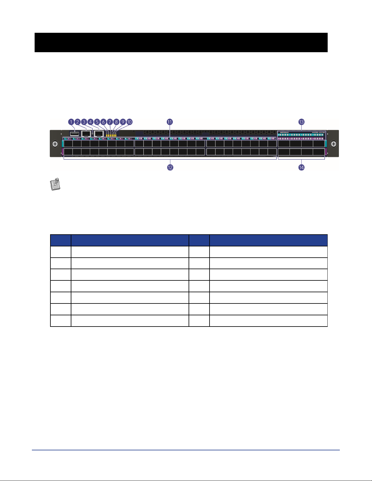
Model M4500-48XF8C
No.
Item
No.
Item
1
USB Port
8
System Info. LED
2
Console Port
9
Power LED
3
Link/Activity LED
10
BMC LED
4
Management Port
11
SFP28 Port LEDs
5
PSU1 LED
12
SFP28 Ports
6
Fan LED
13
QSFP28 Port LEDs
7
PSU2 LED
14
QSFP28 Ports
Models M4500-48XF8C supports forty-eight 25G SFP28 ports and eight 100G QSFP28 ports.
Chassis for model M4500-48XF8C
Front view of the switch
NOTE:
The port LEDs for the odd-numbered ports (that is, for the upper ports) are shown against a
cyan background color.
The port LEDs for even-numbered ports (that is, for the lower ports) are shown against a
purple background color.
NETGEAR M4500 Series Switches Hardware Installation Guide 6

Model M4500-48XF8C
No.
Item
No.
Item
1
AC Power Connector (with Plug
Retainer)
6
PSU2
2
Earth Grounding (M4 screw)
7
Hot-swappable Fan Modules (6)
3
PSU Warning LED
8
Fan LEDs
4
PSU DC LED
9
PSU1
5
PSU AC LED
Rear view of the switch
On the rear panel, the left power supply is PSU2 and the right power supply is PSU1. The fan
modules from the left to the right are FAN6, FAN5, FAN4, FAN3, FAN2, and FAN1.
7 NETGEAR M4500 Series Switches Hardware Installation Guide
Model M4500-48XF8C
LED
State
Description
PSU1 LED
PSU2 LED
(Power Supply Unit
LEDs, bicolor: green
and red)
LED number
One per switch on the front panel
Off
The switch is nonoperational
Red (Solid)
One of the PSUs is operating abnormally
Green (Solid)
Both PSUs are operating normally
FAN LED
(bicolor: green and
red)
LED number
One per switch on the front panel
Red (Solid)
One of the fans is operating abnormally
Green (Solid)
All fans are operating normally
SYS LED
(System LED, bicolor:
green and amber)
LED number
One per switch on the front panel
Off
The switch is nonoperational
Amber (Solid)
The switch is booting
Amber (Blinking)
An equipment even occurred
Green (Solid)
The switch has loaded the agent software code
and is operating normally
Green (Blinking)
The switch is loading the agent software code
PWR LED
(Power LED, single
color: green)
LED number
One per switch on the front panel
Off
The switch is nonoperational or a power failure
occurred
Green (Solid)
Power is provided to the switch
BMC LED
(Baseboard
Management
Controller LED,
bicolor: blue and
amber)
LED number
One per switch on the front panel
Off
The switch is nonoperational
Blue (Slow
Blinking)
The BMC is operating normally
Blue (Fast
Blinking)
A “show switch location” occurred via the BMC
Green (Solid)
The switch has loaded the agent software code
and is operating normally
Green (Blinking)
The switch is loading the agent software code
LED indicators of model M4500-48XF8C
System LEDs
NETGEAR M4500 Series Switches Hardware Installation Guide 8
Model M4500-48XF8C
LED
State
Description
Management Port
Link/Activity LED
(single color: green)
LED number
One per switch on the front panel
Off
No link
Green (Solid)
The port is linked
Green (Blinking)
The port is linked and there is data activity
LED on each fan tray
on the rear panel
(bicolor: green and
red)
LED number
One per fan tray
Off
The fan is not powered on
Green (Solid)
The fan is working normally
Red (Solid)
The fan is working abnormally or failed
LED on each PSU on
the rear panel
(bicolor: green and
amber)
LED number
One per PSU
Off
There is no AC input to the PSU or the AC input
power failed
Green (Solid)
The PSU is working normally
Amber (Solid)
The PSU power or PSU fan is operating
abnormally or the thermal condition is
abornomal
LED
State
Description
25G SFP28 Port
Speed LED (bicolor:
amber and green)
LED number
One per SFP28 port
Off
No link
Amber (Solid)
The port is linked at 25G speed
Amber (Blinking)
The port is linked at 25G speed and there is
data activity at 25G speed
Green (Solid)
The port is linked at 10G speed
Green (Blinking)
The port is linked at 10G speed and there is
data activity at 10G speed
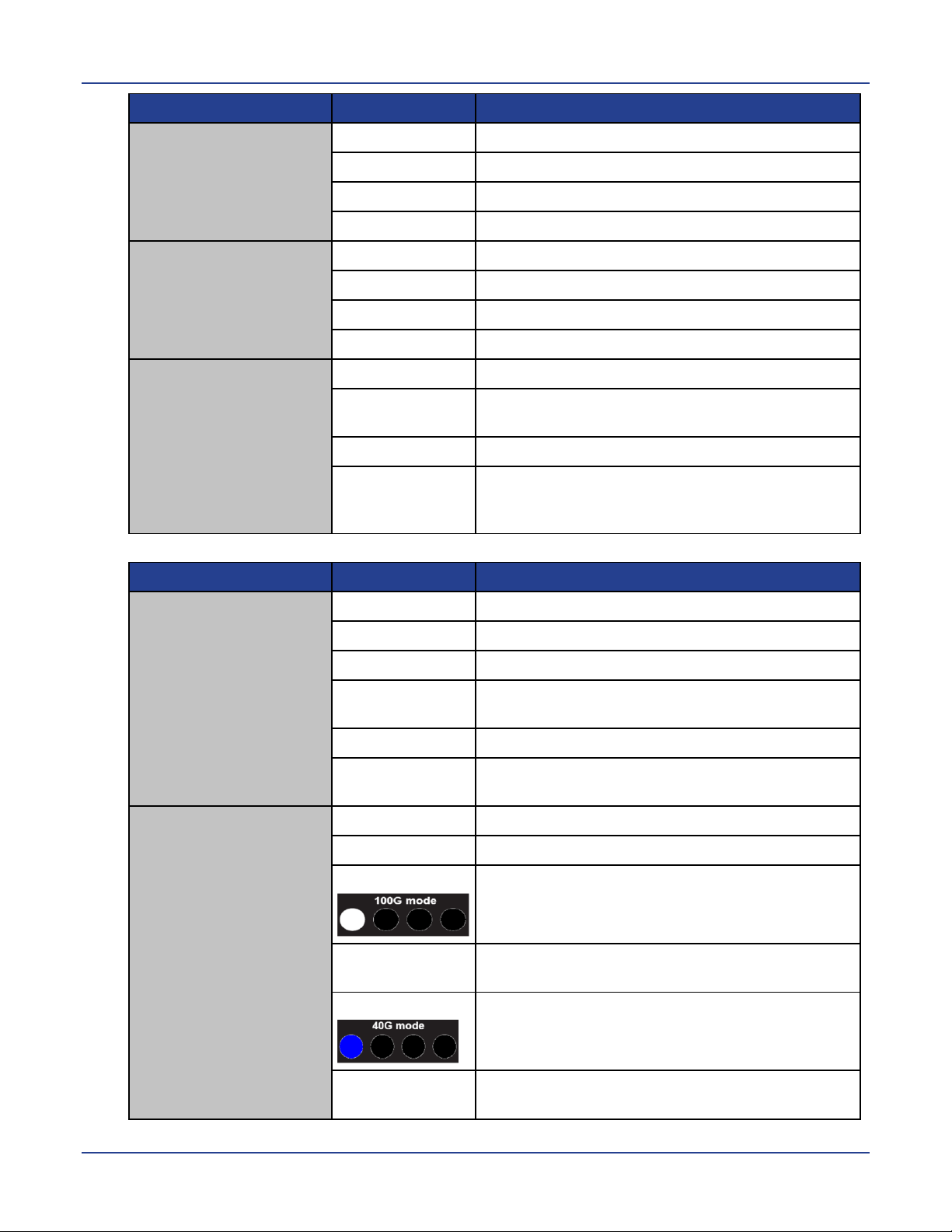
100G QSFP28 Port
Speed LED (bicolor:
white and blue)
LED number
One per QSFP28 port
Off
No link
White (Solid)
The port is linked at 100G speed
White (Blinking)
The port is linked, and there is data activity at
100G speed
Blue (Solid)
The port is linked at 40G speed
Blue (Blinking)
The port is linked at 40G speed and there is
data activity at 40G speed
Data Port LEDs
9 NETGEAR M4500 Series Switches Hardware Installation Guide
Model M4500-48XF8C
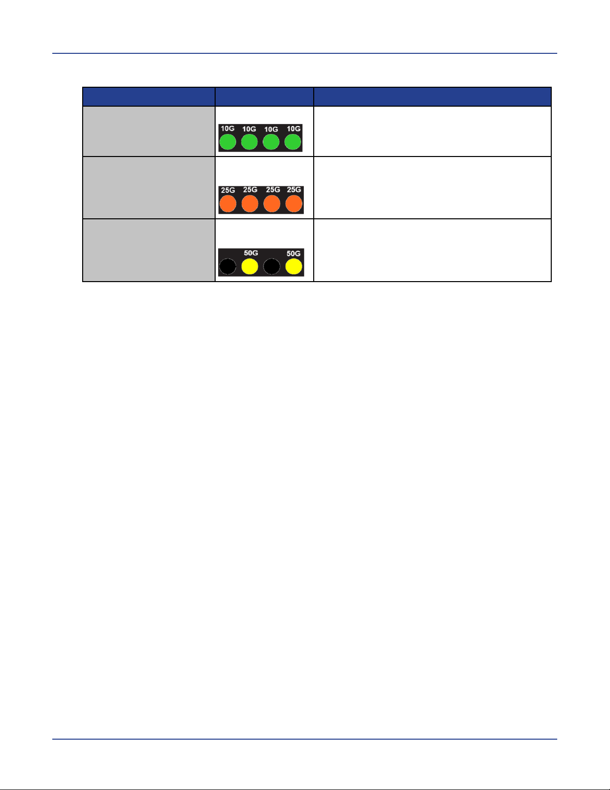
QSFP28 Mode
LED
Description
10G Mode
Each LED is green
The 100G QSFP28 is fan-out to four ports and
operating at 10G port speed
25G Mode
Each LED is
amber
The 100G QSFP28 is fan-out to four 25G
ports and operating at 25G port speed
50G Mode
The 2nd and 4th
LEDs are yellow
The 100G QSFP28 is fan-out and operating to
two 50G ports
There are 4 LEDs for each 100G QSFP28 port to show the fan-out port status. Here are LED
definitions for 100G QSFP28 fan-out use cases.
Ports of model M4500-48XF8C
The switch chassis is equipped with the following ports:
48 SFP28 ports (10/25GbE)
8 QSFP28 ports (10/25/40/50/100GbE speed)
1 Management port
1 Console port
1 USB port
The chassis has 48 SFP28 and 8 QSFP28 ports. Each of these ports uses an optical
transceiver, active optical cable, or direct-attached cable to connect the SFP28 or QSFP28
port to servers and other Ethernet switches. For more information on obtaining the
appropriate SFP28 or QSFP28 modules, refer to “Supported Transceivers and Cables”.
By default, the port speeds are as follows:
The SFP28 ports are set to 10G.
The QSFP28 ports are set to 100G.
If you want to use a higher or lower port speed than the default port speed, manually change
the port speed before you insert the module. For more information see the CLI manual.
The chassis also provides the following system ports:
One management port enables you to manage the switch operation using an RJ-45
Ethernet cable.
One console port enables you to perform the initial configuration by connecting to a PC
with the RJ-45 to DB-9 serial adapter cable.
One USB port provides the option to install a switch runtime image or configuration file
into storage memory.
NETGEAR M4500 Series Switches Hardware Installation Guide 10
 Loading...