

Page 1

Hardware Installation Guide
M4300 Intelligent Edge Series
Fully Managed Stackable Switch
M4300-96X
NETGEAR, Inc.
350 E. Plumeria DriveJanuary 2020
San Jose, CA 95134, USA202-12074-01
Page 2

M4300 Intelligent Edge Series Fully Managed Stackable Switch M4300-96X
Support
Thank you for purchasing this NETGEAR product. You can visit
https://www.netgear.com/support/ to register your product, get help, access the latest
downloads and user manuals, and join our community. We recommend that you use
only official NETGEAR support resources.
Compliance and Conformity
For regulatory compliance information including the EU Declaration of Conformity, visit
https://www.netgear.com/about/regulatory/.
See the regulatory compliance document before connecting the power supply.
Do not use this device outdoors. The PoE source is intended for intra building connection
only.
Trademarks
© NETGEAR, Inc., NETGEAR, and the NETGEAR Logo are trademarks of NETGEAR, Inc.
Any non-NETGEAR trademarks are used for reference purposes only.
Revision History
Number
CommentsPublish DatePublication Part
January 2020201-26351-01
November 2019202-11815-04
June 2018202-11815-03
April 2018202-11815-02
The CD is no longer shipped with product. Removed info on
CD.
Updated branding.
Updated support and compliance section.
Changed the Fan LED behavior for a faulty fan condition from
blinking yellow to solid yellow.
Published the guide in a new format.
Updated the information about port numbering on the
APM402XL port card (see Port Numbering on page 16).
Updated informationabout the multifunction Reset button (see
Multifunction Reset Button on page 23).
Added information about the APM402XL port card and updated
the information about port numbering.
First publication.March 2018202-11815-01
2
Page 3

Contents
Chapter 1 Introduction
Overview................................................................................................6
Features.................................................................................................7
Stacking Concepts................................................................................8
Safety Instructions and Warnings.......................................................9
Chapter 2 Hardware Overview
Hardware Descriptions......................................................................13
Front Panel......................................................................................13
Back Panel.......................................................................................14
System LEDs...................................................................................15
Port Numbering.............................................................................16
Switch Hardware Interfaces...............................................................20
Port Cards and Port LEDs..............................................................20
Cables and Speed..........................................................................21
Multi-Gigabit RJ-45 Ports..............................................................21
10GBASE-X and 1000BASE-X Transceiver Modules and Cables
for SFP+ Ports.................................................................................22
40GBASE-X Transceiver Modules and Cables for QSFP+
Ports.................................................................................................23
Multifunction Reset Button...........................................................23
RJ-45 RS232 Console Port............................................................24
Out-of-Band 1G Ethernet Port......................................................24
USB Port..........................................................................................24
Mini USB Console Port..................................................................25
Power Supply Units............................................................................25
PoE Power Budgets............................................................................25
Chapter 3 Installation
Step 1: Prepare the Site.....................................................................28
Step 2: Protect Against Electrostatic Discharge.............................28
Step 3: Unpack the Switch.................................................................29
Step 4: Install the Switch....................................................................30
Install the Switch in a Rack Using the Front Rack-Mounting
Brackets...........................................................................................30
3
Page 4

M4300 Intelligent Edge Series Fully Managed Stackable Switch M4300-96X
Install the Switch in a Rack Using the Rear Rack-Mounting Brackets
With Rails.........................................................................................31
Install the Switch on a Flat Surface...............................................32
Step 5: Connect PoE and Non-PoE Devices to the Switch............33
Step 6: Install SFP or QSFP Transceiver Modules...........................33
Install SFP Transceiver Modules...................................................33
Install QSFP Transceiver Modules................................................34
Step 7: Install a Power Supply Unit...................................................35
Step 8: Check the Installation Before You Apply Power................36
Step 9: Apply AC Power and Check the LEDs................................37
Optional Step 10: Connect a Console to the Switch.....................37
Chapter 4 Maintenance and Troubleshooting
Replace a Power Supply Unit............................................................40
Troubleshooting Chart.......................................................................41
PoE Troubleshooting Suggestions...................................................42
Additional Troubleshooting Suggestions.......................................42
4
Page 5

1
Introduction
The NETGEAR M4300 Intelligent Edge Series Fully Managed Stackable Switch Model
M4300-96X is a modular, high-performance, IEEE-compliant, 40G access and
aggregation layer switch. The modular design of the switch includes 12 slots for port
cards with support for up to 96 ports so that you can customize the switch for your
network environment and add port cards as needed. The switch supports multispeed
10GBASE-T port cards for copper connections, including Power over Ethernet plus
(PoE+) port cards, SFP+ port cards for 1 Gbps and 10 Gbps fiber connections, and
QSFP+ port cards for 40G fiber connections. The switch is also stackable.
In this guide, the M4300 Intelligent Edge Series Fully Managed Stackable Switch Model
M4300-96X is referred to as the switch.
This hardware installation guide complements the installation guide that came with the
switch.
This chapter serves as an introduction to the switch and includes the following sections:
• Overview
• Features
• Stacking Concepts
• Safety Instructions and Warnings
Note: For more information about the topics that are covered in this manual, visit the
support website at netgear.com/support.
Note: For switch documentation, including the user manual, the command-line interface
manual, and the data sheet, visit netgear.com/support/product/M4300-96X.aspx#docs.
5
Page 6

M4300 Intelligent Edge Series Fully Managed Stackable Switch M4300-96X
Overview
The switch provides a full-width chassis with 12 slots for port cards and two small
form-factor, modular power supply unit (PSU) bays. Each slot can support a 10G port
card with 8 ports for a total of 96 ports on the switch, with each port supporting 10G.
Alternately, each slot can support a 40G port card with 2 ports for a total of twenty-four
40G ports on the switch. Slots 1 through 6 can accept PoE+ port cards, with a total
supported power budget of 1,440W for 48 ports. All 10G Ethernet port cards support
100M/1G/2.5G/5G/10GBASE-T ports. The SFP port cards support 1G/10GBASE-X SFP+
ports in which you can install 1G and 10G transceiver modules (GBICs) or direct-attach
cables (DACs). The QSFP+ port cards support QSFP+ modules, break-out cables, and
DACs.
The switch integrates full-duplex, nonblocking 1.92 terabit per second (Tbps) switch
fabric that provides 10G line rate for all 96 ports or 40G line rate for up to 24 ports.
The switch supports the following port cards:
APM408C. Provides eight 100M/1G/2.5G/5G/10GBASE-T ports.
•
APM408P. Provides eight 100M/1G/2.5G/5G/10GBASE-T PoE+ ports.
•
APM408F. Provides eight 1G/10GBASE-X SFP+ ports in which you can install 1G
•
and 10G GBICs or DACs.
APM402XL. Provides two 40GBASE-X QSFP+ ports in which you can install QSFP+
•
modules, break-out cables, or DACs. For an APM402XL port connection at 40 Gbps,
use modules or cables that are compatible with 40GBASE-SR4, 40GBASE-LR4, and
40GBASE-CR4.
The switch lets you create high-speed connections to a server or network backbone.
For example, you can do the following:
Connect switches to each other with high-speed links
•
Link to high-speed servers
•
Provide 100M/1G/2.5G/5G/10G copper, 1G/10G fiber, and 40G fiber connectivity
•
Connect up to eight switches in a stack to create a high-port-capacity solution with
•
a single point of administration
You would typically rack-mount the switch in a wiring closet or equipment room, either
as a standalone switch or stacked with other switches. The switch is IEEE compliant and
offers low latency for high-speed networking. All ports can automatically negotiate to
the highest speed, which makes the switch also suitable for environments with a mix of
Ethernet, Fast Ethernet, Gigabit Ethernet, and 10-Gigabit Ethernet devices. The 10/100
Mbps ports can operate in half-duplex or full-duplex mode. The 1G/2.5G/5G/10G and
40G ports always operate in full-duplex mode.
Hardware Installation Guide6Introduction
Page 7

M4300 Intelligent Edge Series Fully Managed Stackable Switch M4300-96X
Features
The switch supports the following key hardware features:
Switch ports in various configurations through the use of the following port cards:
•
- APM408C. Provides eight 100M/1G/2.5G/5G/10GBASE-T ports.
- APM408P. Provides eight 100M/1G/2.5G/5G/10GBASE-T PoE+ ports.
- APM408F. Provides eight 1G/10GBASE-X SFP+ ports in which you can install
1G and 10G GBICs or DACs.
- APM402XL. Provides two 40GBASE-X QSFP+ ports in which you can install
QSFP+ modules, break-out cables, or DACs.
Support for 1.92 Tbps switching fabric (all ports line-rate).
•
One out-of-band 1G Ethernet port.
•
One RJ-45 RS232 console port.
•
One mini USB console port.
•
One regular USB port for connection to a storage device.
•
Two PSU bays for small form-factor modular PSUs.
•
Support for stacking on any 10G or 40G port.
•
Full-width, 2U chassis.
•
Full compatibility with IEEE standards:
•
- IEEE 802.3 (Ethernet )
- IEEE 802.3i (10BASE-T)
- IEEE 802.3u (100BASE-TX)
- IEEE 802.3ab (1000BASE-T)
- IEEE 802.3an (10GBASE-T)
- IEEE 802.3z (1000BASE-SX/LX)
- IEEE 802.3ae (10GBASE-SR, 10GBASE-LR)
- IEEE 802.3ba (40GBASE-SR4, 40GBASE-LR4, and 40GBASE-CR4)
-
IEEE 802.3x Full-duplex flow control
- IEEE 802.3ad Link aggregation (LAG with LACP)
-
IEEE 802.3az Energy Efficient Ethernet (EEE)
Hardware Installation Guide7Introduction
Page 8

M4300 Intelligent Edge Series Fully Managed Stackable Switch M4300-96X
-
IEEE 802.3af (PoE)
- IEEE 802.3at (PoE+)
AutoSensing and autonegotiating capabilities for all ports.
•
Auto Uplink™ technology is supported on all ports.
•
Automatic address learning function to build the packet-forwarding information
•
table. The table contains up to 16K Media Access Control (MAC) addresses.
Store-and-forward transmission to remove bad packets from the network.
•
Active flow control to minimize packet loss and frame drops.
•
Half-duplex backpressure control.
•
Per-port status LEDs and system status LEDs.
•
Nonstop Forwarding Failover (NSF) support for the master in a stack.
•
NETGEAR green power-saving features, including energy efficiency mode that fully
•
conforms to the IEEE802.3az standard.
Support for an APS1200W PSU to provide a larger power PoE budget.
•
Stacking Concepts
A single switch can control and manage a stack. This switch is referred to as the stack
master, or simply, the master. Any other members in the stack are referred to as slaves.
All switches in a stack are stack members.
Slaves can download firmware from the master and the master can push firmware to
the slaves.
The master runs the fully operational software of a switch. In addition, the master runs
the master software of the distributed switching application that configures and manages
all slaves. Generally, the master operates the remote slave’s low-level drivers through
the distributed switching application part that is running in the context of the slave.
During stacking setup, the switches autoselect one switch as the master. All other
switches become slaves and are assigned unique stack IDs. One of the slaves is
designated as the backup master. The backup master functions as a slave but can
become the master if the original master fails. In the default configuration, the master
and backup master are assigned unit IDs of 1 and 2, respectively. You can use the local
browser–based management interface to configure different ID assignments. The master
provides a single point of control and management as well as a single interface through
which to control and manage the stack.
Switch software is downloaded separately for each stack member. However, all stack
members must be running the same software version.
Hardware Installation Guide8Introduction
Page 9

M4300 Intelligent Edge Series Fully Managed Stackable Switch M4300-96X
A stack unit can operate in one of the following modes:
A standalone switch runs as a general switch. The standalone unit does not run the
•
stacking application until it is connected to a stack.
A master manages the entire stack and is responsible for the entire stack
•
configuration. All protocols run in the context of the master, which updates and
synchronizes the backup master.
A backup master runs as a slave until it must take over from the master. In addition,
•
the backup master continuously monitors the existence and operation of the master.
If the master fails, the backup master assumes the role of master through a switchover.
A slave runs only a slave version of the distributed switching software, which allows
•
the applications running on the master to control and manage the resources of the
slave.
A stack can contain a mix of up to eight switches. All models support stacking. The
master supports Nonstop Forwarding Failover (NSF).
For information about how to configure stacking through the software, see the user
manual, which you can download by visiting downloadcenter.netgear.com.
Safety Instructions and Warnings
Use the following safety guidelines to ensure your own personal safety and to help
protect your system from potential damage.
To reduce the risk of bodily injury, electrical shock, fire, and damage to the equipment,
observe the following precautions:
This product is designed for indoor use only in a temperature-controlled (0–50°C or
•
32–122°F) and humidity-controlled (90 percent maximum relative humidity,
noncondensing) environment.
Any device that is located outdoors and connected to this product must be properly
grounded and surge protected.
To the extent permissible by applicable law, failure to follow these guidelines can
result in damage to your NETGEAR product, which might not be covered by
NETGEAR’s warranty.
Observe and follow service markings:
•
- Do not service any product except as explained in your system documentation.
- Opening or removing covers that are marked with the triangular symbol with a
lightning bolt can expose you to electrical shock. We recommend that only a
trained technician services components inside these compartments.
Hardware Installation Guide9Introduction
Page 10

M4300 Intelligent Edge Series Fully Managed Stackable Switch M4300-96X
If any of the following conditions occur, unplug the product from the electrical outlet
•
and replace the part or contact your trained service provider:
- The power cable, extension cable, or plug is damaged.
-
An object fell into the product.
- The product was exposed to water.
- The product was dropped or damaged.
-
The product does not operate correctly when you follow the operating
instructions.
Keep your system away from radiators and heat sources. Also, do not block cooling
•
vents.
Do not spill food or liquids on your system components, and never operate the
•
product in a wet environment. If the system gets wet, see the appropriate section in
your troubleshooting guide, or contact your trained service provider.
Do not push any objects into the openings of your system. Doing so can cause fire
•
or electric shock by shorting out interior components.
Use the product only with approved equipment.
•
Allow the product to cool before removing covers or touching internal components.
•
Operate the product only from the type of external power source indicated on the
•
electrical ratings label. If you are not sure of the type of power source required,
consult your service provider or local power company.
To avoid damaging your system, be sure that the voltage selection switch (if provided)
•
on the power supply is set to match the power at your location:
-
115V, 60 Hz in most of North and South America and some Far Eastern countries
such as South Korea and Taiwan
- 100V, 50 Hz in eastern Japan and 100V, 60 Hz in western Japan
-
230V, 50 Hz in most of Europe, the Middle East, and the Far East
Be sure that attached devices are electrically rated to operate with the power available
•
in your location.
Use only approved power cables. If you were not provided with a power cable for
•
your system or for any AC-powered option intended for your system, purchase a
power cable approved for your country. The power cable must be rated for the
product and for the voltage and current marked on the product electrical ratings
label. The voltage and current rating of the cable must be greater than the ratings
marked on the product.
Hardware Installation Guide10Introduction
Page 11

M4300 Intelligent Edge Series Fully Managed Stackable Switch M4300-96X
To help prevent electric shock, plug the system and peripheral power cables into
•
properly grounded electrical outlets.
The peripheral power cables are equipped with three-prong plugs to help ensure
•
proper grounding. Do not use adapter plugs or remove the grounding prong from
a cable. If you must use an extension cable, use a three-wire cable with properly
grounded plugs.
Observe extension cable and power strip ratings. Make sure that the total ampere
•
rating of all products plugged into the extension cable or power strip does not
exceed 80 percent of the ampere ratings limit for the extension cable or power strip.
To help protect your system from sudden, transient increases and decreases in
•
electrical power, use a surge suppressor, line conditioner, or uninterruptible power
supply (UPS).
Position system cables and power cables carefully. Route cables so that they cannot
•
be stepped on or tripped over. Be sure that nothing rests on any cables.
Do not modify power cables or plugs. Consult a licensed electrician or your power
•
company for site modifications.
Always follow your local and national wiring rules.
•
Hardware Installation Guide11Introduction
Page 12

2
Hardware Overview
This chapter describes the switch hardware features.
The chapter includes the following sections:
• Hardware Descriptions
• Switch Hardware Interfaces
• Power Supply Units
• PoE Power Budgets
12
Page 13
M4300 Intelligent Edge Series Fully Managed Stackable Switch M4300-96X
Hardware Descriptions
This section describes the front panel and back panel components and the system LEDs.
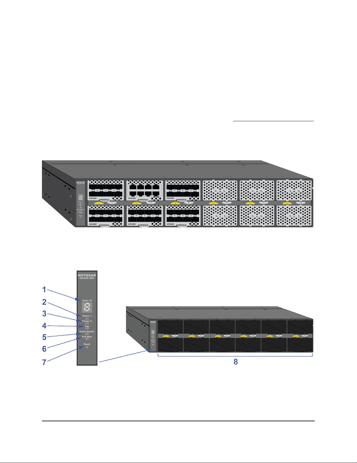
Front Panel
The front panel of the switch provides the system LEDs and 12 slots in which you can
install port cards. Each port card provides its own LEDs (see Port Cards and Port LEDs
on page 20).
The following figure shows the front panel with six port cards and six blank covers
installed in the switch.
Figure 1. Front panel with six port cards and six blank covers installed
The following figure shows the front panel without any port cards or blank covers installed
in the switch.
Figure 2. System LEDs and front panel showing empty chassis
Hardware Installation Guide13Hardware Overview
Page 14

M4300 Intelligent Edge Series Fully Managed Stackable Switch M4300-96X
Table 1. Front panel and system LEDs
DescriptionNumber
Stack ID LED1
Power 1 LED for the PSU 1 bay on the back panel2
Power 2 LED for the PSU 2 bay on the back panel3
Fan LED4
Stack Master LED5
PoE Max LED6
Reset button (see Multifunction Reset Button on page 23)7
8
Slots for port cards (see Port Cards and Port LEDs on page 20)
The slots in the upper row are numbered 1 through 6 from left to right. The slots in the lower row are
numbered 7 through 12 from left to right. For information about port numbering (interface conventions)
for the ports on the port cards, see Port Numbering on page 16.
For information about the system LEDs,
see System LEDs on page 15.
Back Panel
The back panel of the switch provides a console port, out-of-band (OOB) port with
associated LEDs, USB port, mini USB console port, two bays for power supply units
(PSUs), three fixed fans, and the switch label.
The following figure shows the back panel.
Figure 3. Back panel components
Hardware Installation Guide14Hardware Overview
Page 15

M4300 Intelligent Edge Series Fully Managed Stackable Switch M4300-96X
Table 2. Back panel components
DescriptionNumber
1
Out-of-band (OOB) 1G Ethernet port (see Out-of-Band 1G Ethernet Port on page 24) with a left LED
that indicates the speed and a right LED that indicates the link and activity (see System LEDs on page
15)
RJ-45 RS232 (115200, N, 8, 1) console port (see RJ-45 RS232 Console Port on page 24)2
USB 2.0 port (see USB Port on page 24)3
Mini USB (115200, N, 8, 1) console port (see Mini USB Console Port on page 25)4
Bay 1 (PSU 1) for a modular PSU (see Power Supply Units on page 25)5
Fixed fans for front-to-back air flow6
Switch label7
Bay 2 (PSU 2) for a second modular PSU (see Power Supply Units on page 25)8
System LEDs
The following table describes the system LEDs on the front panel of switch and the
single LED on the back panel of the switch.
Table 3. System LEDs
Front panel LEDs
Stack ID LED
Power 1 LED (for the
PSU 1 bay)
and
Power 2 LED (for the
PSU 2 bay)
Fan LED
DescriptionLED
The Stack LED contains segments that can indicate the stack unit number of the switch.
Solid green indicating a number. The switch is a member of a stack. The LED displays
the stack unit number.
Solid green indicating E. The switch functions in economy (ECO) mode with all port
LEDs turned off.
Off. The switch is not a member of a stack.
Solid green. The power supply unit is present, is supplying power to the switch, and is
functioning normally.
Solid yellow. The switch is starting.
Blinking yellow. The switch failed to start correctly or another failure occurred.
Off. Power is not supplied to the switch.
Solid green. The fans are functioning normally.
Solid yellow. One or more fans failed.
Off. Power is not supplied to the switch. The fans are off.
Hardware Installation Guide15Hardware Overview
Page 16

M4300 Intelligent Edge Series Fully Managed Stackable Switch M4300-96X
Table 3. System LEDs (Continued)
DescriptionLED
Stack Master LED
PoE Max LED
Back panel LEDs
OOB Ethernet port
Solid green. The switch is functioning as a master in a stack.
Off. The switch is not a member of a stack or is functioning as a slave in a stack.
Off. Sufficient (more than 7W of) PoE power is available on the switch.
Solid yellow. Less than 7W of PoE power is available on the switch.
Blinking yellow. At least once during the previous two minutes, less than 7W of PoE
power was available on the switch.
Left side speed LED:
Solid green. The link speed is 1000 Mbps.
Solid yellow. The link speed is 10 Mbps or 100 Mbps.
Off. No link is established on the port.
Right side link and activity LED:
Solid green. A valid link is established on the port.
Blinking green. The port is transmitting or receiving packets.
Off. No link is established on the port.
For information about the LEDs on the port cards, see Port Cards and Port LEDs on
page 20.
Port Numbering
The ports (interfaces) on the port cards in the slots are numbered switch unit number/slot
number/port number.
For the APM408C, APM408P, and APM408F port cards, the ports on the port cards in
the slots are numbered as described in the following table. (In the interface convention
examples in the table, the switch is designated as unit number 1.)
Table 4. Port numbering for the APM408C, APM408P, and APM408F port cards
Slot
Number
1
2
3
4
Slot
Location
row
row
row
row
Port Card Upper
Port Numbers
Port Numbers
Interface ConventionPort Card Lower
1/1/1, 1/1/2, 1/1/3, and so on through 1/1/82, 4, 6, 81, 3, 5, 7Upper
1/2/1, 1/2/2, 1/2/3, and so on through 1/2/82, 4, 6, 81, 3, 5, 7Upper
1/3/1, 1/3/2, 1/3/3, and so on through 1/3/82, 4, 6, 81, 3, 5, 7Upper
1/4/1, 1/4/2, 1/4/3, and so on through 1/4/82, 4, 6, 81, 3, 5, 7Upper
Hardware Installation Guide16Hardware Overview
Page 17

M4300 Intelligent Edge Series Fully Managed Stackable Switch M4300-96X
Table 4. Port numbering for the APM408C, APM408P, and APM408F port cards (Continued)
Slot
Number
5
6
7
8
9
10
11
12
Slot
Location
row
row
row
row
row
row
row
row
Port Card Upper
Port Numbers
Interface ConventionPort Card Lower
Port Numbers
1/5/1, 1/5/2, 1/5/3, and so on through 1/5/82, 4, 6, 81, 3, 5, 7Upper
1/6/1, 1/6/2, 1/6/3, and so on through 1/6/82, 4, 6, 81, 3, 5, 7Upper
1/7/1, 1/7/2, 1/7/3, and so on through 1/7/82, 4, 6, 81, 3, 5, 7Lower
1/8/1, 1/8/2, 1/8/3, and so on through 1/8/82, 4, 6, 81, 3, 5, 7Lower
1/9/1, 1/9/2, 1/9/3, and so on through 1/9/82, 4, 6, 81, 3, 5, 7Lower
1/10/1, 1/10/2, 1/10/3, and so on through 1/10/82, 4, 6, 81, 3, 5, 7Lower
1/11/1, 1/11/2, 1/11/3, and so on through 1/11/82, 4, 6, 81, 3, 5, 7Lower
1/12/1, 1/12/2, 1/12/3, and so on through 1/12/82, 4, 6, 81, 3, 5, 7Lower
Slots 1 through 6 support PoE port cards. If you install a PoE port card in another slot,
the ports provide connectivity but no PoE power.
The following figure shows the port numbering in port cards that are installed in slots
1 and 7 of a switch with unit number 1.
Hardware Installation Guide17Hardware Overview
Page 18

M4300 Intelligent Edge Series Fully Managed Stackable Switch M4300-96X
The numbering of the ports on the APM402XL port card is different from the other port
cards. You can use a 40G port either with a break-out cable, in which case the single
40G port can support up to four individual 10G ports, or with a connection to another
single 40G port.
Port 1 (the left 40G port on the port card) uses the following numbering:
If connected with a break-out cable to four individual 10G ports, the port numbers
•
are 1, 2, 3, and 4.
If connected to another single 40G port, the port number is 1. In that situation, only
•
port number 1 is used and port numbers 2, 3, and 4 are not used on the port card.
Port 2 (the right 40G port on the port card) uses the following numbering:
If connected with a break-out cable to four individual 10G ports, the port numbers
•
are 5, 6, 7, and 8.
If connected to another single 40G port, the port number is 5. In that situation, only
•
port number 5 is used and port numbers 6, 7, and 8 are not used on the port card.
For example, if a switch with unit number 1 includes an APM402XL port card in slot 9,
port 1 on the port card is connected to four individual port cards, and port 2 on the port
card is connected to another single 40G port, the port numbering is as follows: 1/9/1,
1/9/2, 1/9/3, 1/9/4, and 1/9/5.
For the APM402XL port card, the ports on the port cards in the slots are numbered as
described in the following table. (In the interface convention examples in the table, the
switch is designated as unit number 1.)
Hardware Installation Guide18Hardware Overview
Page 19

M4300 Intelligent Edge Series Fully Managed Stackable Switch M4300-96X
Table 5. Port numbering for the 40G ports on the APM402XL port card
Slot
Number
1
2
3
4
5
6
Location
row
row
row
row
row
row
PortSlot
Port
Numbers
for 10G
Interface ConventionPort
Numbers
for 40G
For 10G: 1/1/1, 1/1/2, 1/1/3, and 1/1/4. For 40G: 1/1/1.11, 2, 3, 41Upper
For 10G: 1/1/5, 1/1/6, 1/1/7, and 1/1/8. For 40G: 1/1/5.55, 6, 7, 82
For 10G: 1/2/1, 1/2/2, 1/2/3, and 1/2/4. For 40G: 1/2/1.11, 2, 3, 41Upper
For 10G: 1/2/5, 1/2/6, 1/2/7, and 1/2/8. For 40G: 1/2/5.55, 6, 7, 82
For 10G: 1/3/1, 1/3/2, 1/3/3, and 1/3/4. For 40G: 1/3/1.11, 2, 3, 41Upper
For 10G: 1/3/5, 1/3/6, 1/3/7, and 1/3/8. For 40G: 1/3/5.55, 6, 7, 82
For 10G: 1/4/1, 1/4/2, 1/4/3, and 1/4/4. For 40G: 1/4/1.11, 2, 3, 41Upper
For 10G: 1/4/5, 1/4/6, 1/4/7, and 1/4/8. For 40G: 1/4/5.55, 6, 7, 82
For 10G: 1/5/1, 1/5/2, 1/5/3, and 1/5/4. For 40G: 1/5/1.11, 2, 3, 41Upper
For 10G: 1/5/5, 1/5/6, 1/5/7, and 1/5/8. For 40G: 1/5/5.55, 6, 7, 82
For 10G: 1/6/1, 1/6/2, 1/6/3, and 1/6/4. For 40G: 1/6/1.11, 2, 3, 41Upper
For 10G: 1/6/5, 1/6/6, 1/6/7, and 1/6/8. For 40G: 1/6/5.55, 6, 7, 82
7
8
9
10
11
12
For 10G: 1/7/1, 1/7/2, 1/7/3, and 1/7/4. For 40G: 1/7/1.11, 2, 3, 41Lower
row
For 10G: 1/7/5, 1/7/6, 1/7/7, and 1/7/8. For 40G: 1/7/5.55, 6, 7, 82
For 10G: 1/8/1, 1/8/2, 1/8/3, and 1/8/4. For 40G: 1/8/1.11, 2, 3, 41Lower
row
For 10G: 1/8/5, 1/8/6, 1/8/7, and 1/8/8. For 40G: 1/8/5.55, 6, 7, 82
For 10G: 1/9/1, 1/9/2, 1/9/3, and 1/9/4. For 40G: 1/9/1.11, 2, 3, 41Lower
row
For 10G: 1/9/5, 1/9/6, 1/9/7, and 1/9/8. For 40G: 1/9/5.55, 6, 7, 82
For 10G: 1/10/1, 1/10/2, 1/10/3, and 1/10/4. For 40G: 1/10/1.11, 2, 3, 41Lower
row
For 10G: 1/10/5, 1/10/6, 1/10/7, and 1/10/8. For 40G: 1/10/5.55, 6, 7, 82
For 10G: 1/11/1, 1/11/2, 1/11/3, and 1/11/4. For 40G: 1/11/1.11, 2, 3, 41Lower
row
For 10G: 1/11/5, 1/11/6, 1/11/7, and 1/11/8. For 40G: 1/11/5.55, 6, 7, 82
For 10G: 1/12/1, 1/12/2, 1/12/3, and 1/12/4. For 40G: 1/12/1.11, 2, 3, 41Lower
row
For 10G: 1/12/5, 1/12/6, 1/12/7, and 1/12/8. For 40G: 1/12/5.55, 6, 7, 82
Hardware Installation Guide19Hardware Overview
Page 20

M4300 Intelligent Edge Series Fully Managed Stackable Switch M4300-96X
Switch Hardware Interfaces
This section describes the hardware interfaces of the switch.
Port Cards and Port LEDs
The switch supports the following hot-swappable ports cards, which you can install in
the switch slots on the front panel:
APM408C. Provides eight 100M/1G/2.5G/5G/10GBASE-T ports.
•
APM408P. Provides eight 100M/1G/2.5G/5G/10GBASE-T PoE+ ports. Slots 1–6 of
•
the switch support PoE and PoE+.
APM408F. Provides eight 1G/10GBASE-X SFP+ ports in which you can install 1G
•
and 10G transceiver modules (GBICs) or direct attach cables (DACs).
APM402XL. Provides two fiber 40GBASE ports that support Quad Small Form-factor
•
Pluggable Plus (QSFP+) modules, 40G break-out cables, or 40G DACs.
The following table describes the port LEDs on the port cards.
Table 6. Port LEDs on the port cards
Link, Speed, and Activity LED BehaviorPort Type
RJ-45 ports
Multispeed
10GBASE-T
Multispeed
10GBASE-T with
PoE
Solid green. A 10 Gbps link is established.
Blinking green. 10 Gbps traffic is being processed.
Solid yellow. A 100 Mbps, 1000 Mbps, 2.5 Gbps, or 5 Gbps link is established.
Blinking yellow. 100 Mbps, 1000 Mbps, 2.5 Gbps, or 5 Gbps traffic is being processed.
Off. No link is established.
Solid blue. A 10 Gbps link is established. The port is delivering PoE.
Blinking blue. 10 Gbps traffic is being processed. The port is delivering PoE.
Solid purple. A 100 Mbps, 1000 Mbps, 2.5 Gbps, or 5 Gbps link is established. The port is
delivering PoE.
Blinking purple. 100 Mbps, 1000 Mbps, 2.5G, or 5G traffic is being processed. The port is
delivering PoE.
Solid light blue. The port is delivering PoE. No Ethernet link is established.
Solid green. A 10 Gbps link is established. The port is not delivering PoE.
Blinking green. 10 Gbps traffic is being processed. The port is not delivering PoE.
Solid yellow. A 100 Mbps, 1000 Mbps, 2.5 Gbps, or 5 Gbps link is established. The port is not
delivering PoE.
Blinking yellow. 100 Mbps, 1000 Mbps, 2.5 Gbps, or 5 Gbps traffic is being processed. The
port is not delivering PoE.
Off. No link is established and the port is not delivering PoE.
Hardware Installation Guide20Hardware Overview
Page 21

M4300 Intelligent Edge Series Fully Managed Stackable Switch M4300-96X
Table 6. Port LEDs on the port cards (Continued)
Link, Speed, and Activity LED BehaviorPort Type
SFP+ ports
SFP+
1G/10GBASE-X
QSFP+ ports
QSFP+
40GBASE-X
Solid green. A 10 Gbps SFP+ transceiver module link is established.
Blinking green. 10 Gbps traffic is being processed.
Solid yellow. A 1000 Mbps SFP transceiver module link is established.
Blinking yellow. 1000 Mbps traffic is being processed.
Off. No link is established.
Solid green. A 40 Gbps QSFP+ module link is established.
Blinking green. 40 Gbps traffic is being processed.
Off. No link is established.
For more information about the port cards, see the NETGEAR Fully Managed Switch
Port Cards Installation Guide, which you can download by visiting
downloadcenter.netgear.com.
Cables and Speed
The following table describes the network cables that you can use for the switch copper
connections and the speeds that these cables can support, up to 100 meters (328 feet).
Table 7. Cables and speeds
Cable TypeSpeed
Category 5 (Cat 5) or higher rated100 Mbps
Category 5e (Cat 5e) or higher rated1 Gbps, 2.5 Gbps, or 5 Gbps
Category 6a (Cat 6a) or higher rated10 Gbps
Note: For speeds of 10 Gbps, if the cable length is shorter than 180 feet (55 meters),
you can use a Category 6 (Cat 6) cable.
Multi-Gigabit RJ-45 Ports
Port cards with multi-Gigabit copper RJ-45 ports support 100M/1G/2.5G/5G/10GBASE-T
with autosensing. When you insert a cable into an RJ-45 port, the switch automatically
ascertains the maximum speed (100 Mbps, 1 Gbps, 2.5 Gbps, 5 Gbps, or 10 Gbps) of
the attached device. For devices that support 100 Mbps, the switch automatically
ascertains the duplex mode (half-duplex or full-duplex). All ports support a Category 5
(Cat 5) unshielded twisted-pair (UTP) cable or higher-rated Ethernet cable terminated
Hardware Installation Guide21Hardware Overview
Page 22

M4300 Intelligent Edge Series Fully Managed Stackable Switch M4300-96X
with an 8-pin RJ-45 connector. For more information about Ethernet cables, see Cables
and Speed on page 21.
To simplify the procedure for attaching devices, all RJ-45 ports support Auto Uplink
technology. This technology allows attaching devices to the RJ-45 ports with either
straight-through or crossover cables.
When you insert a cable into an RJ-45 port on a port card, the switch automatically
performs the following actions:
Senses whether the cable is a straight-through or crossover cable.
•
Determines whether the link to the attached device requires a normal connection
•
(such as when you are connecting the port to a computer) or an uplink connection
(such as when you are connecting the port to a router, switch, or hub).
Automatically configures the RJ-45 port to enable communications with the attached
•
device. The Auto Uplink technology compensates for setting uplink connections
while eliminating concern about whether to use crossover or straight-through cables
when you attach devices.
10GBASE-X and 1000BASE-X Transceiver Modules and Cables for SFP+ Ports
To enable high-speed fiber and long-distance connections on the switch, port cards
with SFP+ fiber ports accommodate standard 10G and 1G SFP+ transceiver modules
(gigabit interface converters, or GBICs) and direct attach cables (DACs), which are sold
separately from the port cards.
The port cards supports the following NETGEAR SFP and SFP+ transceiver modules
and cables:
Short reach transceiver modules:
•
- AGM731F. SFP transceiver 1000BASE-SX, SFP multimode LC GBIC
- AGM734. SFP transceiver 1000BASE-T, SFP copper RJ-45 GBIC
- AXM761. SFP+ transceiver 10GBASE-SR, SFP+ multimode LC GBIC
Long reach transceiver modules:
•
- AGM732F. SFP transceiver 1000BASE-LX, SFP single mode LC GBIC
- AXM762. SFP+ transceiver 10GBASE-LR, SFP+ single mode LC GBIC
- AXM764. SFP+ transceiver 10GBASE-LR Lite, SFP+ single mode LC GBIC
1G/10GBASE-T transceiver modules:
•
- AXM765. SFP+ transceiver 10GBASE-T, SFP+ copper RJ-45 GBIC
Hardware Installation Guide22Hardware Overview
Page 23

M4300 Intelligent Edge Series Fully Managed Stackable Switch M4300-96X
Direct attach cables:
•
- AXC761. SFP+ 1m direct attach cable
- AXC763. SFP+ 3m direct attach cable
- AXC765. SFP+ 5m direct attach cable
- AXC767. SFP+ 7m direct attach cable
- AXC7610. SFP+ 10m direct attach cable
- AXC7615. SFP+ 15m direct attach cable
- AXC7620. SFP+ 20m direct attach cable
For more information about NETGEAR SFP and SFP+ transceiver modules and cables,
visit netgear.com/business/products/switches/modules-accessories.
40GBASE-X Transceiver Modules and Cables for QSFP+ Ports
To enable very high-speed fiber and long-distance connections on the switch, port
cards with Quad Small Form-Factor Pluggable Plus (QSFP+) fiber ports accommodate
standard 40G transceiver modules (gigabit interface converters, or GBICs), break-out
cables, and direct attach cables (DACs), which are sold separately from the port cards.
At this time, NETGEAR does not offer any QSFP+ transceiver modules or cables. However,
you can obtain any third-party, IEEE-compliant, 40GBASE-X transceiver module or cable
for use with the switch.
Multifunction Reset Button
The switch provides a recessed multifunction Reset button on the front panel so that
you can either restart the switch or return the switch to its factory default settings, causing
all custom settings to be erased.
Note: The option to return the switch to its factory default settings by using the Reset
button is supported in software release 12.0.6 and later releases.
To restart the switch or return the switch to its factory default settings:
1. Insert a device such as a straightened paper clip into the opening.
2.
Do one of the following:
Restart the switch. Press the Reset button for about two seconds.
•
WARNING: Do not press the button for more than five seconds!
Hardware Installation Guide23Hardware Overview
Page 24

M4300 Intelligent Edge Series Fully Managed Stackable Switch M4300-96X
The switch restarts but retains its custom settings. During this process, the Power
LED lights amber.
Return the switch to its factory default settings. Press the Reset button for at
•
least five seconds.
The switch restarts and returns to its factory default settings. During this process,
the Power LED lights amber.
RJ-45 RS232 Console Port
The back panel of the switch provides one RJ-45 RS232 port for console access only.
This serial port is configured for 115200 baud, eight data bits, one stop bit, and no
parity. The product package includes one console cable with one DB9 connector and
one RJ-45 connector. You can use this cable to connect the RJ-45 RS232 console port
on the switch to a DB9 port on a VT100-compatible terminal or a Windows-based
computer that runs VT100 terminal emulation software.
Out-of-Band 1G Ethernet Port
The back panel of the switch provides one out-of-band (OOB) 1000BASE-T RJ-45
Ethernet port that lets you access the switch over its local browser interface or over a
Telnet or SSH connection.
USB Port
The back panel of the switch provides one USB 2.0 port that lets you upgrade firmware
from a disk and back up the configuration to a storage device and that allows for the
collection of a memory dump for debugging purposes.
A device that you attach to the USB port must comply with the following requirements:
The USB device must support USB 2.0.
•
The USB device must support the FAT32 or VFAT file type. The NTFS file type is not
•
supported.
Because of hardware limitations, the write and read speed to and from a USB device is
about 1 Mbps.
Note: In a stack, only the switch that functions as the master can detect and manage
an attached USB device.
Hardware Installation Guide24Hardware Overview
Page 25

M4300 Intelligent Edge Series Fully Managed Stackable Switch M4300-96X
Mini USB Console Port
The back panel of the switch provides one mini USB port for console access only. This
port is configured for 115200 baud, eight data bits, one stop bit, and no parity. The
product package includes one USB console cable with one mini B connector and one
type A connector. You can use this cable to connect the mini USB console port on the
switch to a USB port on a VT100-compatible terminal or a Windows-based computer
that runs VT100 terminal emulation software.
Note: For you to be able to use the mini USB port and access the switch from a
Windows-based computer that runs VT100 terminal emulation software, you must install
the USB driver on the computer. To download the VT100 terminal emulation software
and Windows USB driver, visit https://www.netgear.com/support/, enter your model
number in the search box, and click the Downloads button on the product page.
Power Supply Units
The switch can support the following power supply unit (PSU) configurations for dual
PSU configurations:
One APS600W PSU
•
Two APS600W PSUs
•
One APS1200W PSU
•
Two APS1200W PSUs
•
One APS600W PSU and one APS1200W PSU
•
The PSUs provide one AC OK LED. During normal operation, this LED lights green to
indicate that the PSU is receiving power.
For more information about the PSUs, see the NETGEAR Power Supplies Units for
Managed Switches Installation Guide, which you can download by visiting
downloadcenter.netgear.com.
PoE Power Budgets
The PoE power budget depends on the installed PSU or PSUs. The following table
describes the possible PoE power budgets. To calculate the PoE power budget, subtract
Hardware Installation Guide25Hardware Overview
Page 26

M4300 Intelligent Edge Series Fully Managed Stackable Switch M4300-96X
from the available power 100W for the switch system and 38W for each installed port
card.
Table 8. PSU configuration and PoE budgets
PSU Configuration
One APS1200W
Power
Input
PoE Power BudgetAvailable
Power
600W–110W–(38W x number of port cards)600W110 VACSingle APS600W
600W–110W–(38W x number of port cards)600W220 VAC
1200W–110W–(38W x number of port cards)1200W110 VACDual APS600W
1200W–110W–(38W x number of port cards)1200W220 VAC
1050W–110W–(38W x number of port cards)1050W110 VACSingle APS1200W
1200W–110W–(38W x number of port cards)1200W220 VAC
1440W (You do not need to subtract wattage.)2100W110 VACDual APS1200W
1440W (You do not need to subtract wattage.)2400W220 VAC
1650W–110W–(38W x number of port cards)1650W110 VACOne APS600W and
1800W–110W–(38W x number of port cards)1800W220 VAC
Hardware Installation Guide26Hardware Overview
Page 27

3
Installation
This chapter describes the installation procedures for the switch.
Switch installation involves the steps described in the following sections:
• Step 1: Prepare the Site
• Step 2: Protect Against Electrostatic Discharge
• Step 3: Unpack the Switch
• Step 4: Install the Switch
• Step 5: Connect PoE and Non-PoE Devices to the Switch
• Step 6: Install SFP or QSFP Transceiver Modules
• Step 7: Install a Power Supply Unit
• Step 8: Check the Installation Before You Apply Power
• Step 9: Apply AC Power and Check the LEDs
• Optional Step 10: Connect a Console to the Switch
27
Page 28

M4300 Intelligent Edge Series Fully Managed Stackable Switch M4300-96X
Step 1: Prepare the Site
We recommend that you install the switch at a location where access is restricted to
qualified service personnel only.
Before you install the switch, make sure that the operating environment meets the site
requirements that are listed in the following table.
Table 9. Site requirements
RequirementsCharacteristics
Mounting
Access
Power source
Cabling
Environmental
Rack-mount installations. Use a 19-inch (48.3-centimeter) EIA standard equipment rack
that is grounded and physically secure. You also need the rack-mount kit that is supplied
with the switch.
Desktop installations. Provide a flat table or shelf surface.
Locate the switch in a position that allows you to access the front panel slots, view the
front panel system LEDs, and access the PSU bays and ports on the back panel.
Use the AC power cord that is supplied with the switch. Make sure that the AC outlet is
not controlled by a wall switch, which can accidentally turn off power to the outlet and
the switch.
Route cables to avoid sources of electrical noise such as radio transmitters, broadcast
amplifiers, power lines, and fluorescent lighting fixtures.
Temperature. Install the switch in a dry area with an ambient temperature between 0ºC
and 50ºC (32ºF and 122ºF). Keep the switch away from heat sources such as direct
sunlight, warm-air exhausts, hot-air vents, and heaters.
Operating humidity. The maximum relative humidity of the installation location must
not exceed 90%, noncondensing.
Ventilation. Do not restrict airflow by covering or obstructing air inlets on the sides of
the switch. Keep at least 2 inches (5.08 centimeters) free on all sides for cooling. The
room or wiring closet in which you install the switch must provide adequate airflow.
Operating conditions. Keep the switch at least 6 feet (1.83 meters) away from the nearest
source of electromagnetic noise, such as a photocopy machine.
Step 2: Protect Against Electrostatic Discharge
WARNING: Static electricity can harm delicate components inside your system. To
prevent static damage, discharge static electricity from your body before you touch any
of the electronic components, such as the microprocessor. You can do so by periodically
touching an unpainted metal surface on the switch.
Hardware Installation Guide28Installation
Page 29

M4300 Intelligent Edge Series Fully Managed Stackable Switch M4300-96X
You can also take the following steps to prevent damage from electrostatic discharge
(ESD):
When unpacking a static-sensitive component from its shipping carton, leave it in
•
the antistatic package until you are ready to install it. Just before unwrapping the
antistatic package, discharge static electricity from your body.
Before moving a sensitive component, place it in an antistatic container or package.
•
Handle all sensitive components in a static-safe area. If possible, use antistatic floor
•
pads, workbench pads, and an antistatic grounding strap.
Step 3: Unpack the Switch
The following figure shows the package contents for the switch.
Figure 4. Package contents
Check the contents of the boxes to make sure that all items are present before installing
the switch.
Hardware Installation Guide29Installation
Page 30

M4300 Intelligent Edge Series Fully Managed Stackable Switch M4300-96X
To check the package contents:
1.
Place the container on a clean flat surface, and cut all straps securing the container.
2.
Unpack the hardware from the boxes by carefully removing the hardware and placing
it on a secure and clean surface.
3. Remove all packing material.
4.
Verify that the package contains the following items:
a.
Switch model M4300-96X (The previous figure shows the chassis without port
cards and blank covers.)
b. USB console cable with one mini B connector and one type A connector
c.
Power cord for the PSU
d. Console cable with one DB9 connector and one RJ-45 connector
e. Rack-mounting screws
Rear rack-mounting brackets with rails
f.
g. Front rack-mounting brackets
h.
Rubber footpads for tabletop installation
i. Installation guide
j. Rubber caps to protect unused RJ-45 ports and SFP+ ports
5.
If any item is missing or damaged, contact your local NETGEAR reseller for
replacement.
Step 4: Install the Switch
You would typically mount the switch in a standard 19-inch (48.26-centimeter) network
equipment rack. However, you can install the switch on a flat surface.
Install the Switch in a Rack Using the Front Rack-Mounting Brackets
The switch package includes front rack-mounting brackets and screws for installation
in a 19-inch rack.
To install the switch in a rack using the front rack-mounting brackets:
1.
Attach the supplied front rack-mounting brackets to the sides of the switch.
2. Insert the supplied rack-mounting screws through each bracket and into the bracket
mounting holes in the switch.
Hardware Installation Guide30Installation
Page 31

M4300 Intelligent Edge Series Fully Managed Stackable Switch M4300-96X
3. Tighten the screws with a No. 1 Phillips screwdriver to secure each bracket.
4. Align the mounting holes in the brackets with the holes in the rack, and insert two
pan-head screws with nylon washers through each bracket and into the rack.
5. Tighten the screws with a No. 2 Phillips screwdriver to secure the brackets to the
rack.
Figure 5. Installing the switch in a rack using the front rack-mounting brackets
Install the Switch in a Rack Using the Rear Rack-Mounting Brackets With Rails
The switch package includes rear rack-mounting brackets with rails and screws for
installation in a 19-inch rack.
To install the switch in a rack using the rear rack-mounting brackets with rails:
1.
Attach the supplied rear rack-mounting brackets with rails to the sides of the switch.
2. Insert the supplied rack-mounting screws through each bracket and into the bracket
mounting holes in the switch.
3. Tighten the screws with a No. 1 Phillips screwdriver to secure each bracket.
Hardware Installation Guide31Installation
Page 32

M4300 Intelligent Edge Series Fully Managed Stackable Switch M4300-96X
4.
Adjust the length of the brackets, align the mounting holes in the brackets with the
holes in the rack, and insert two pan-head screws with nylon washers through each
bracket and into the rack.
5. Tighten the screws with a No. 2 Phillips screwdriver to secure the brackets to the
rack.
Figure 6. Installing the switch in a rack using the rear rack-mounting brackets with rails
Install the Switch on a Flat Surface
The switch ships with four self-adhesive rubber footpads. The rubber footpads cushion
the switch against shock and vibrations. They also provide ventilation space between
stacked switches.
To install the switch on a flat surface:
Stick one rubber footpad on each of the four concave spaces on the bottom of the
switch.
Hardware Installation Guide32Installation
Page 33

M4300 Intelligent Edge Series Fully Managed Stackable Switch M4300-96X
Step 5: Connect PoE and Non-PoE Devices to the Switch
Note: If you do not use APM408C or APM408P port cards, you can skip this step.
The following procedure describes how to connect devices to an RJ-45 port on an
APM408C or APM408P port card. The switch supports Auto Uplink technology, which
allows you to attach devices using either straight-through or crossover cables. Use a
Category 5 (Cat 5), Cat 5e, or Cat 6 cable that is terminated with an RJ-45 connector
(see Cables and Speed on page 21).
Note: Ethernet specifications limit the cable length between the switch and the attached
device to 328 feet (100 meters).
To connect a PoE or non-PoE device to an RJ-45 port on an APM408C or APM408P
port card:
1. Connect the device to an RJ-45 port on a port card.
2.
Verify that all cables are installed correctly.
Step 6: Install SFP or QSFP Transceiver Modules
If you do not use APM408F or APM402XL port cards, you can skip this step.
Install SFP Transceiver Modules
Note: If you do not use APM408F port cards, you can skip this step.
This procedure describes how to install an SFP transceiver module into an SFP+ port
on an APM408F port card.
Hardware Installation Guide33Installation
Page 34

M4300 Intelligent Edge Series Fully Managed Stackable Switch M4300-96X
To install an SFP transceiver module into an SFP+ port on an APM408F port card:
1. Insert the transceiver module into the SFP+ port.
CAUTION: The edges of the SFP+ port opening are sharp. We recommend that
you do not touch the port opening with your fingers but use a tool to insert the
transceiver module.
2.
Press firmly on the flange of the transceiver module to seat it securely into the
connector.
Figure 7. Inserting an SFP transceiver module
Install QSFP Transceiver Modules
Note: If you do not use APM402XL port cards, you can skip this step.
This procedure describes how to install a QSFP transceiver module into a QSFP+ port
on an APM402XL port card.
Hardware Installation Guide34Installation
Page 35

M4300 Intelligent Edge Series Fully Managed Stackable Switch M4300-96X
To install a QSFP transceiver module into a QSFP+ port on an APM402XL port card:
1. Insert the transceiver module into the QSFP+ port.
CAUTION: The edges of the QSFP+ port opening are sharp. We recommend that
you do not touch the port opening with your fingers but use a tool to insert the
transceiver module.
2.
Press firmly on the flange of the transceiver module to seat it securely into the
connector.
Figure 8. Inserting a QSFP transceiver module
Step 7: Install a Power Supply Unit
Note: If the switch came with a power supply unit (PSU) installed and you do not want
to install a second PSU, you can skip this step.
The back panel of the switch provides two PSU bays. For information about the PSUs
that are supported for the switch, see Power Supply Units on page 25.
If the switch came with a PSU installed, it is installed in the PSU bay on the left, which is
marked PSU 1. You can install a second PSU in the power supply bay on the right, which
is marked PSU 2. The switch can continue to operate while you install a second PSU.
Hardware Installation Guide35Installation
Page 36

M4300 Intelligent Edge Series Fully Managed Stackable Switch M4300-96X
To install a PSU in either the PSU 1 bay or PSU 2 bay:
1.
Pull out the cover plate from the bay.
2. Insert the PSU into the bay, and gently push the PSU into the bay until the latch locks.
CAUTION: When you insert the PSU, do not use unnecessary force. Doing so can
damage the connectors on the rear of the PSU and on the midplane.
3.
Connect the end of the power cord to the power receptacle on the PSU.
4. Plug the AC power cord into a power source such as a wall socket or power strip.
When you apply power to the PSU, depending on the bay in which you installed the
PSU, the Power 1 LED or Power 2 LED on the front panel of the switch lights. If the
associated Power LED does not light, check to see that the power cord is plugged
in correctly and that the power source is good.
Step 8: Check the Installation Before You Apply Power
Before you apply power to the switch, perform the steps that are described in this
section.
To check the installation:
1. Inspect the equipment thoroughly.
2.
Verify that all cables are installed correctly.
3.
Check cable routing to make sure that cables are not damaged or creating a safety
hazard
4. Make sure that all equipment is mounted properly and securely.
Hardware Installation Guide36Installation
Page 37

M4300 Intelligent Edge Series Fully Managed Stackable Switch M4300-96X
Step 9: Apply AC Power and Check the LEDs
The switch does not provide an on/off switch. The power cord connection controls the
power. Before connecting the power cord, select an AC outlet that is not controlled by
a wall switch, which can turn off power to the switch.
To apply AC power and check the LEDs:
1.
Connect the end of the power cord to the power receptacle on the PSU on back
panel of the switch.
If you installed two PSUs, do this for both PSUs.
2. When you apply power, the Power LED that is associated with the bay in which you
installed the PSU lights.
The Power 1 LED on the front panel is associated with the PSU 1 bay. The Power 2
LED is associated with the PSU 2 bay. If a Power LED does not light, check to see
that the power cord is plugged in correctly and that the power source is good.
3.
Check to see that the system LEDs on the front panel function as expected.
For more information, see System LEDs on page 15.
4.
Check to see that the LEDs on the port cards functions as expected.
For more information, see Port Cards and Port LEDs on page 20.
Optional Step 10: Connect a Console to the Switch
This procedure is optional.
You can manage the switch through its local browser interface or through a console
that is attached to the switch. To be able to use a console, you need the following items:
A computer with a Windows, MAC, or Linux operating system, a UNIX workstation,
•
or a VT100/ANSI terminal.
Depending on the connector type at your computer or terminal, use one of the
•
following cables, both of which are included in the product package:
-
Ethernet cable for use with the RJ-45 RS232 console port
-
Mini USB cable for use with the mini USB console port
Hardware Installation Guide37Installation
Page 38

M4300 Intelligent Edge Series Fully Managed Stackable Switch M4300-96X
To connect a console to the switch:
1. Connect either the RJ-45 RS232 cable or the mini USB cable to the appropriate port
on the back panel of the switch.
For more information, see RJ-45 RS232 Console Port on page 24 or Mini USB Console
Port on page 25.
2.
Connect the other end of the cable to your computer, workstation, or terminal.
On a computer with a Windows operating system, you can use HyperTerminal
•
or install another terminal emulator such as Tera Term.
On a computer with a MAC operating system, you can use ZTerm.
•
On a UNIX workstation, you can use a terminal emulator such as TIP.
•
3.
If you attach a computer or workstation, start a terminal emulation application, which
you must configure to use the following settings:
Baud rate. 115,200 bps
•
Data bits. 8
•
Parity. None
•
Stop bit. 1
•
Flow control. None
•
After you connect a console to the switch, you can configure the switch. For
information about configuring the switch, see the command-line interface (CLI)
manual, which you can download by visiting downloadcenter.netgear.com.
For information about configuring the switch through its local browser interface, see
the user manual, which you can also download by visiting
downloadcenter.netgear.com.
Hardware Installation Guide38Installation
Page 39

4
Maintenance and Troubleshooting
This chapter provides information about maintaining and troubleshooting the switch.
The chapter includes the following sections:
• Replace a Power Supply Unit
• Troubleshooting Chart
• PoE Troubleshooting Suggestions
• Additional Troubleshooting Suggestions
39
Page 40

M4300 Intelligent Edge Series Fully Managed Stackable Switch M4300-96X
Replace a Power Supply Unit
You can replace a power supply unit (PSU). If the switch is operating with two PSUs, you
can replace one PSU while the other PSU enables the switch to remain powered on and
functioning.
To remove one PSU and reinstall another PSU in the same PSU bay:
1.
If the switch functions with a single PSU only, disconnect the power cord from the
PSU and let the switch power down.
If your switch functions with two PSUs, you do not need to power down the switch
and can perform a hot swap.
2.
Remove the PSU from its bay by moving the release latch to the left and pulling the
extraction handle.
3. Insert the other PSU into the bay, and gently push the PSU into the bay until the latch
locks.
CAUTION: When you insert the PSU, do not use unnecessary force. Doing so can
damage the connectors on the rear of the PSU and on the midplane.
4.
Connect the end of the power cord to the power receptacle on the PSU.
5. Plug the AC power cord into a power source such as a wall socket or power strip.
When you apply power to the PSU, depending on the bay in which you installed the
PSU, the Power 1 LED or Power 2 LED on the front panel of the switch lights. If the
associated Power LED does not light, check to see that the power cord is plugged
in correctly and that the power source is good.
Troubleshooting
Hardware Installation Guide40Maintenance and
Page 41

M4300 Intelligent Edge Series Fully Managed Stackable Switch M4300-96X
Troubleshooting Chart
The following table lists symptoms, possible causes, and possible solutions for problems
that might occur.
Table 10. Troubleshooting chart
Possible SolutionPossible CauseSymptom
A Power LED is off.
Combined speed and activity
LED is off when the port is
connected to a device.
File transfer is slow or
performance is degraded.
A segment or device is not
recognized as part of the
network.
Power is not supplied to the
switch.
Port connection is not
working.
One possible cause is that a
broadcast storm occurred and
that a network loop
(redundant path) was created.
One or more devices are not
properly connected, or
cabling does not meet
Ethernet guidelines.
Check the power cable connections at the switch
and the power source.
Make sure that all cables are used correctly and
comply with the Ethernet specifications.
Check the crimp on the connectors and make sure
that the plug is properly inserted and locked into
the port at both the switch and the connecting
device.
Make sure that all cables are used correctly and
comply with the Ethernet specifications.
Check for a defective port, cable, port card, or
module by testing them in an alternate
environment where all products are functioning.
Break the loop by making sure that only one path
exists from any networked device to any other
networked device. After you connect to the local
browser interface of the switch, you can configure
the Spanning Tree Protocol (STP) to prevent
network loops.
Verify that the cabling is correct.
Make sure that all connectors are securely
positioned in the required ports. It is possible that
equipment was accidentally disconnected.
Combined speed and activity
LED is blinking continuously
on all connected ports and the
network is disabled.
A unit is linked to a stack but
does not join the stack.
Troubleshooting
A network loop (redundant
path) was created.
The stacking ports of the new
unit are configured differently
from the stack, or the unit is
configured as a standalone
unit.
Break the loop by making sure that only one path
exists from any networked device to any other
networked device. After you connect to the local
browser interface of the switch, you can configure
the Spanning Tree Protocol (STP) to prevent
network loops.
Remove the unit from the stack. Use the local
browser interface to configure the unit as a
stackable unit, with combo links used as the
stacking ports.
Hardware Installation Guide41Maintenance and
Page 42

M4300 Intelligent Edge Series Fully Managed Stackable Switch M4300-96X
PoE Troubleshooting Suggestions
Here are some tips for correcting PoE problems that might occur:
Make sure that the PoE Max LED on the front panel of the switch is off. If the PoE
•
Max LED is solid yellow, disconnect one or more PoE devices to prevent PoE
oversubscription. Start by disconnecting the device from the highest-numbered
port.
Make sure that the Ethernet cables are plugged in correctly. For each powered
•
device (PD) that is connected to the switch, the associated port LED on the port card
lights the appropriate color (see Port Cards and Port LEDs on page 20). If the port
LED lights a color that indicates that no PoE power is being delivered, a PoE fault
occurred and PoE halted because of one of the conditions that are listed in the
following table.
Table 11. PoE fault conditions and possible solutions
Possible SolutionPoE Fault Condition
A PoE-related short circuit occurred on the port.
The PoE power demand of the PD exceeded the maximum level that
the switch permits. The maximum level is 15.4W for a PoE connection
or 30W for a PoE+ connection.
The PoE current on the port exceeded the classification limit of the
PD.
The PoE voltage of the port is outside the range that the switch permits.
The problem is most likely with the
attached PD. Check the condition of
the PD or restart the PD by
disconnecting and reconnecting the
PD.
Restart the switch to see if the
condition resolves itself.
Additional Troubleshooting Suggestions
If the suggestions in the troubleshooting chart do not resolve the problem, see the
following troubleshooting suggestions:
Network adapter cards. Make sure that the network adapters that are installed in
•
the computers are in working condition and the software driver was installed.
Configuration. If problems occur after you alter the network configuration, restore
•
the original connections and determine the problem by implementing the new
Hardware Installation Guide42Maintenance and
Troubleshooting
Page 43

M4300 Intelligent Edge Series Fully Managed Stackable Switch M4300-96X
changes one step at a time. Make sure that cable distances, repeater limits, and
other physical aspects of the installation do not exceed the Ethernet limitations.
Switch integrity. If necessary, verify the integrity of the switch by resetting it. To
•
reset the switch, disconnect the AC power from the switch and then reconnect the
AC power. If the problem continues, contact NETGEAR Technical Support. For more
information, visit the support website at netgear.com/support.
Autonegotiation. The RJ-45 multispeed Ethernet ports negotiate speed, duplex
•
mode (if applicable), and flow control if the device at the other end of the link
supports autonegotiation. If the device does not support autonegotiation, the switch
determines only the speed correctly, and the duplex mode defaults to half-duplex.
Troubleshooting
Hardware Installation Guide43Maintenance and
 Loading...