

Page 1
NETGEAR ProSAFE
®
M4300 Intelligent Edge Series
Frequently Asked Questions
1. What is the M4300 series?
The M4300 Stackable L3 Managed Switch Series come with 40G, 10G and 1G models in a variety of form factors and PoE+ full provisioning. All
10 Gigabit ports are independent and 1G backward compatible for progressive transition to 10G speeds. The M4300 Switch Series delivers L2/
L3/L4 and IPv4/IPv6 rich services for mid-enterprise edge and SMB core with unrivalled ease of use: 10/40 Gigabit models can seamlessly stack
with 1 Gigabit models, enabling line-rate spine and leaf stacking topologies. Non-stop forwarding (NSF) virtual chassis architecture provides
advanced High Availability (HA) with hitless failover across the stack. Dual redundant, modular power supplies equipping full width models
contribute to business continuity management. M4300 is ideal for server aggregation with Auto-iSCSI prioritization: two half-width M4300
switches can be installed in a single rack space for redundant Top of Rack installations. Layer 3 feature set includes static and policy-based
routing, RIP, VRRP, OSPF, and PIM dynamic routing – as standard. Perfect for wireless access, unified communications and IP video, the NETGEAR
M4300 Switch Series is also ready for the future, with Soware-defined Network (SDN) and OpenFlow 1.3 enabled for your network.
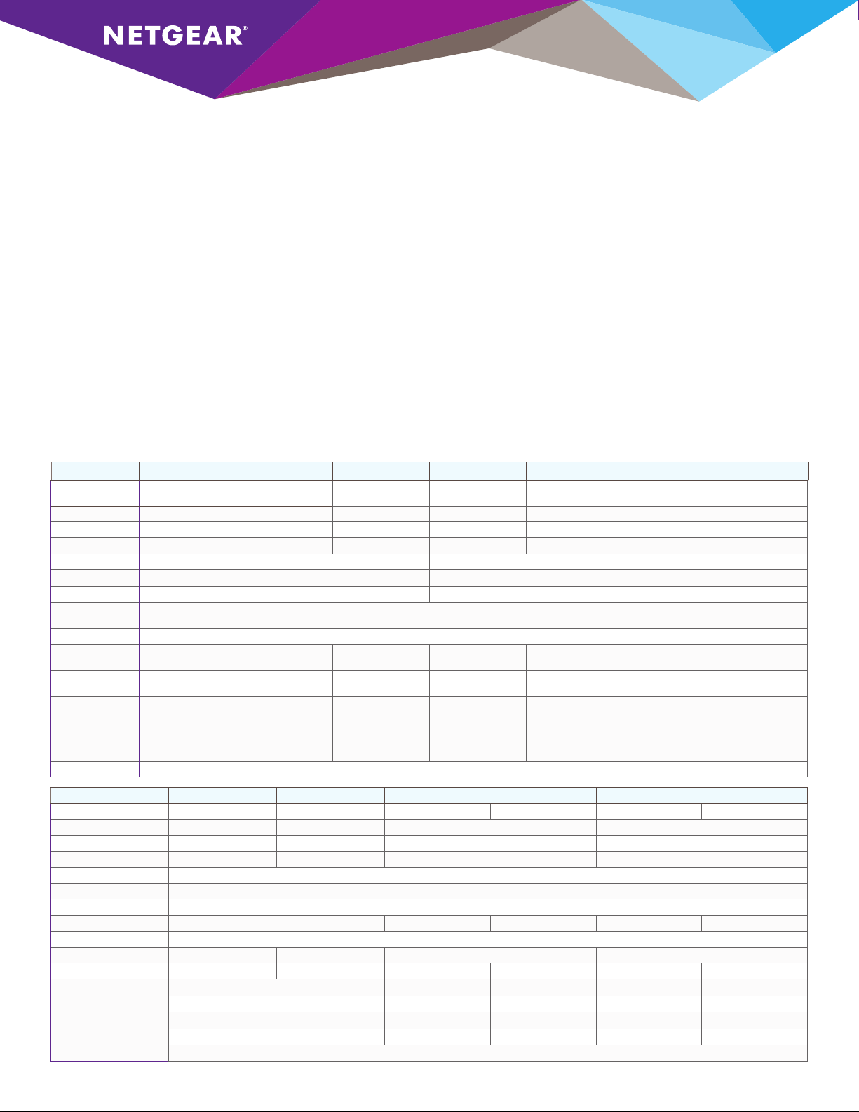
2. What are the available M4300 models?
Model Name M4300- 8X8F M430 0-12X 12F M4300 -24X M4300 -24X24F M4300-48X M4300 -96X
Model Number XS M4316S XSM 4324S XSM 4324C S XSM4348S XSM4348CS
10G BASE -T RJ45 8 ports 12 p or t s 24 po rts 24 po rts 48 ports Up to 96 por ts (up to 48xPoE+)
1G/10G SFP+ 8 ports 12 p or t s 4 shared po rts 24 po rts 4 shared ports Up to 96 por ts
40G QS FP+ Up to 24 ports
Form Factor Half-width Full width Modular
Rack Mount 1- or 2-unit 1U 1-u ni t 1U 1-unit in 2U
Power Supply Modular 1 bay Modular 2 bays
Included PSU
Fans Front-to-back
No ise @25°C 36.9dB 36.9dB 37dB 35.8d B 40.3dB Without PoE - 35.8dB
Max Power
Consumption
PoE+ Budget 1xAPS60 0W - 0W
Management Ethernet: Out-of-band 1G port Console: RJ45 RS232 and Mini-USB Storage: USB
49 Watts 97 Wat ts 125 Wa tt s 161 Wa tts 237 Watts
(1) A PS2 50W
XSM4396K0 (Em pty Switch)
XSM4396K1 (Starter Kit)
XSM4396K0 - no PSU
XSM4396K1 - (1) APS600W
Max PoE load - 66.8d B
Withou t PoE - 566 Watt s
With 1,440W PoE - 2,006 Wat ts
2xAPS600W shared - 634W
1xAPS1200W - 720W
2xAPS1200W redundant - 720W
APS600W+APS1200W shared - 1,084W
2xAPS1200W shared - 1,440W
Model Name M4 30 0-2 8G M4300-52G M4300 -28G- PoE+ M4300-52G -PoE+
Model Number GSM 4328S GSM4352S G SM4328PA GSM 4328P B GSM4352PA GSM4352PB
10/100/10 00 RJ 45 24 po rts 48 ports 24 ports PoE+ 48 ports PoE+
10G BASE -T RJ45 2 ports 2 ports 2 ports 2 ports
1G/10G SFP+ 2 ports 2 ports 2 ports 2 ports
Form Factor Full width
Rack Mount 1-u ni t 1U
Power Supply Modular 2 bays
Included PSU (1) A PS15 0W (1) A PS550 W (1) APS1000W (1) A PS550 W (1) APS1000W
Fans Front-to-back
No ise @25°C 30.3dB 31.5dB 39.8dB 39.8dB
Max Power Consumption 34.5 Watts 4 7.4 W atts 797 Watt s 833.2 Watts 865 Watts 1,628 Wat ts
PoE+ Budget
@110V AC
PoE+ Budget
@220V AC
Management Ethernet: Out-of-band 1G port Console: RJ45 RS232 and Mini-USB Storage: USB
With 1 PSU, o r 2 PSUs Redundant Mode:
With 2 PSUs Shared Mo de:
With 1 PSU, o r 2 PSUs Redundant Mode:
With 2 PSUs Shared Mo de: 720 Watts 720 Watt s 720 Watts 1,440 Wa tt s
480 Watt s 630 Wat ts 480 Watt s 591 Watts
720 Watts 720 Watt s 720 Watts 1,010 W at ts
480 Watt s 720 Wat ts 480 Watt s 860 Watts
Page 2

3. The M4300 comes with half-width 10G models: how
does it work?
M4300 half-width models come with two rack-mount kits: 1-unit and
2-unit kits. To install a single half-width switch in a single rack space,
you will find one regular short bracket and one long mounting bracket.
To install two half-width switches in a single rack space, you will find a
pair of inside and outside middle mounts. Aer installing these middle
mounts, you can slide the inside middle mounts on the le switch into
the outside middle mounts on the right switch. Then you can attach
the supplied short mounting brackets to the le side of the le switch
and to the right side of the right switch to rack them into a single U.
4. Are the 10G copper/fiber ports “Combo”?
All 10G ports are fully independent on M4300-8X8F, M4300-12X12F,
M4300-24X24F, M4300-96X, M4300-28G, M4300-52G, M430028G-PoE+ and M4300-52G-PoE+ models.
Only M4300-24X and M4300-48X show 4-port SFP+ combo (shared
with 4 10GBASE-T copper ports).
5. Are there any pre-configured stacking ports?
No, all 40G and 10G ports are configured in Ethernet mode by
default. Any 40G or 10G port (copper, fiber) and any media type
(RJ45, SFP+, DAC) can be used for stacking on any M4300 model.
Port configuration can be easily changed to Stack mode in Web GUI
(System/ Stacking / Advanced / Stack-port Configuration) or using
CLI command <<#stack-port unit/slot/port stack >> in Stack Global
Configuration section.
6. The M4300-96X is modular: how does it work?
As a new member of the M4300 Layer 3 Stackable Family, the
NETGEAR M4300-96X is a 2RU modular switch that comes
either empty or pre-populated with 48 SFP+ ports, supporting
1.92 terabits per second (Tbps) of bandwidth across 96-port
100M/1G/2.5G/5G/10GBASE-T (RJ-45) with first 48 ports capable
of PoE+, 96-port 1G/10GBASE-X (SFP+), 24-port 40GBASE-X
(QSFP+), or a combination. The M4300-96X scales up to 96 ports
of 10G Ethernet by multiple of 8 ports, or up to 24 ports of 40G
Ethernet by multiple of 2 ports. With 12 open slots and two redundant
power supplies, the 96X allows for granularity between copper and
fiber and headroom for organizations who buy infrastructure for the
long term. You may configure the M4300-96X online at
www.netgear.com/96x-config.
7. What are the ports and power supply options for
M4300-96X?
XSM4396K0 is the ordering SKU number for the M4300-96X empty
switch (no PSU) and XSM4396K1 is the starter kit including the
switch, 48-port SFP+ and one 600W PSU. All 12 slots for the port
cards run horizontally across the front of the switch. APM408C port
card features 8-port 100M/1G/2.5G/5G/10GBASE-T (copper RJ45).
APM408P port card features 8-port 100M/1G/2.5G/5G/10GBASE-T
with PoE+ (copper RJ45). APM408F port card features 8-port
1G/10GBASE-X (fiber SFP+). APM402XL port card features 2-port
40GBASE-X (QSFP+). The 2 slots for the power supplies are on the
switch rear and can receive APS600W PSU for non-PoE operations
or APS1200W for PoE applications. PoE over 10G is supported up
to 48 x 10G PoE+ 30W per system: only the first 6 slots (top) can
deliver power to the APM408P port cards. When inserted in last slots
(bottom), the APM408P behave like APM408C. The various PoE
budgets are as follows: 634 Watts PoE budget with 1 x APS600W
PSU; 634 Watts PoE budget with 2 x APS600W PSUs in shared EPS
mode; 720 Watts PoE budget with 1 x APS1200W PSU; 720 Watts
PoE budget with 2 x APS1200W PSUs in redundant RPS mode; 1,084
Watts PoE budget with APS600W + APS1200W PSUs in shared EPS
mode; 1,440 Watts PoE budget with 2 x APS1200W PSUs in shared
EPS mode.
8. Are the M4300-96X port cards “hot plug” or
“hot swap”?
When the M4300-96X is up and running, any new port card inserted
in one empty slot gets instantly provisioned by the system and
operational. As such, APM port cards can be considered “hot plug”.
When the M4300-96X is up and running, it is possible to remove
one port card from one slot and replace it by a new one from same
model. In this case, the APM port card is “hot swap” and the new
one is operational immediately. When the M4300-96X is up and
running, when one port card is removed from one slot and replaced by
another model, the new port card isn’t operational until the previous
port card gets un-provisioned by the system. The previous port card
can be removed in M4300-96X Web GUI, or using the CLI in Global
Config mode. If this the unit 1 and the slot number 8, you can use the
command (M4300-96X) (Config)#no slot 1/8. Aer the previous
port card is removed in the soware, the new port card model is
operational in this slot, but please note that the previous port-related
configuration was removed from this slot as well. If you don’t want to
lose the previous port-related configuration for this slot, you shouldn’t
remove the port card from the system using GUI or CLI – you should
reboot the M4300-96X switch instead. During the boot, the system
will detect the new port card in this slot and provision it, letting the
port-configuration for this slot untouched in startup-config and
running-config configuration files.
9. Which 40G QSFP+ transceivers and DAC should be
used with APM402XL port card?
The APM402XL is a 2-port QSFP+ port card for M4300-96X modular
switch. The APM402XL port card supports third-party QSFP+
transceivers and QSFP+ DAC passive/active cables if they are QSFP+
MSA compliant. The following list shows third-party modules that
NETGEAR successfully tested as interoperable with APM402XL port
card and M4300-96X switch on the date of 01/30/2018:
Cisco® modules:
•Cisco 40GBASE-SR4 QSFP+ transceiver module for MMF, 4-lanes,
850-nm wavelength, 12-fiber MPO/MTP connector (QSFP-40G-SR4)
•Cisco 40GBASE-SR4 (IEEE 802.3ba Spec.) QSFP+ transceiver
module for MMF, 4-lanes, 850-nm wavelength, 12-fiber MPO/MTP
connector (QSFP-40G-SR4-S)
Page 3

•Cisco 40GBASE-LR4 QSFP 40G transceiver module for Single Mode
Fiber, 4 CWDM lanes in 1310nm window Muxed inside module, Duplex
LC connector, 10km, 40G Ethernet rate only (QSFP-40G-LR4-S)
•Cisco 40GBASE-CSR4 QSFP+ transceiver module for MMF, 4-lanes,
850-nm wavelength, 12-fiber MPO/MTP connector, 300 m reach
with OM3 fiber (QSFP-40G-CSR4)
•Cisco 40G QSFP Bi-Directional transceiver module, Duplex
Multi-mode Fiber, LC Duplex connector, 100m reach with OM3
fiber (QSFP-40G-SR-BD)
•Cisco 40GBASE-CR4 QSFP+ direct-attach copper cable,
1 meter passive (QSFP-H40G-CU1M)
•Cisco 40GBASE-CR4 QSFP+ direct-attach copper cable,
3 meter passive (QSFP-H40G-CU3M)
•Cisco 40GBASE-CR4 QSFP+ direct-attach copper cable,
5 meter passive (QSFP-H40G-CU5M)
•Cisco 40GBASE-CR4 QSFP+ direct-attach copper cable,
7 meter active (QSFP-H40G-ACU7M)
Cisco is a registered trademark of Cisco Technology, Inc.
HPE® Modules:
•HPE X140 40G QSFP+ MPO SR4 Transceiver (JG325A)
•HPE X140 40G QSFP+ LC LR4 SM 10km 1310nm Transceiver
(JG661A)
•HPE X140 40G QSFP+ LC BiDi 100m MM Transceiver (JL251A)
•HPE X240 40G QSFP+ to QSFP+ 1m Direct Attach Copper Cable
(JG326A)
•HPE X240 40G QSFP+ to QSFP+ 3m Direct Attach Copper Cable
(JG327A)
•HPE X240 40G QSFP+ to QSFP+ 5m Direct Attach Copper Cable
(JG328A)
HPE is registered trademark of Hewlett-Packard Enterprise Company.
10. The M4300 oers PoE+, spine and leaf resiliency and
10G stacking in a virtual chassis footprint. What are the
primary reasons to select the M4300 over the M6100
Chassis?
M4300 is cost eective solution for PoE+ edge deployment, midsize
server/storage top-of-rack and SMB dependable core. While M4300
nonstop forwarding and master hitless failover oers unique high
availability for stack architectures, the M6100 chassis provides the
following, unmatched benefits:
•High speed fabric with 80G half-duplex 160G full duplex access
to the backplane for each M6100 blade (1G blades line-rate to the
fabric and 10G blades 3:1 oversubscription) which is must faster
than comparable M4300 stack topologies. This would correspond
to eight 10G ports used for any switch to switch interconnect in
M4300 stack.
•Centralized power management system with N+1 power
redundancy at the chassis level (one redundant PSU for the entire
chassis, when M4300 switches require one redundant PSU per switch)
•Modular and redundant architecture with everlasting passive
backplane and highly reliable fabric-based design
•Modular PoE+ (30 watts per port) and UPOE (60 watts per
po r t s) allow to turn PoE on, with easy upgrade, easy downgrade
(M4300 switches are fixed PoE+ or non-PoE switches)
•Advanced soware features with BGP and DCB (including
DCBX 802.1Qaz; Priority Flow Control PFC; Enhanced Transmission
Selection ETS and FCoE FIP Snooping)
11. What are ring topologies and associated benefits?
Common for intermediate distribution frames (IDF) in K-12, horizontal
or vertical ring stacking topologies, or dual ring topologies greatly
simplify deployments at the edge and bring network resiliency with
distributed uplinks in aggregation to the core. While reducing the
number of logical units to manage, stacking also brings network
resiliency with distributed uplinks in aggregation to the core:
•Horizontal or vertical ring topologies makes sense with Gigabit models
when inter-switch links oversubscription requirements aren’t critical
•Up to (8) M4300 switches can be aggregated using a virtual
backplane and a single console or web management interface
•M4300 PoE and non-PoE versions are highly cost-eective at the
edge, with built-in 10GBASE-T and SFP+ fiber uplinks and no hidden
costs
•While any 10 Gigabit port can be used for stacking, SFP+ ports can
be reserved for fiber uplinks to the core
•10 Gigabit copper ports can be used for local stacking ring topology
and unused 10 Gigabit fiber ports can connect remote switches to
the stack
•Ideally the two top switches connecting back to the core should
have priority settings forcing their roles as “management unit” and
“backup unit” respectively
•This way, management unit hitless failover and nonstop forwarding
ensures no single point of failure:
- Nonstop Forwarding (NSF) enables the stack to secure forwarding
end-user trac on all other switches when the management unit
fails
- Instant failover from management unit to backup management
unit is hitless for the rest of the stack
- Since both the management unit and the backup unit connect
to the core using distributed link aggregation (LACP), there is no
possible service interruption while the backup management unit
takes over
- All other switches in the stack keep forwarding L2 and L3 trac in
and out, while backup unit guarantees connectivity to the core
•Other lower end solutions are causing service interruptions across
the entire stack without NSF and hitless failover
Page 4

12. What are redundant top-of-rack topologies and
associated benefits?
For midsize server installations, two half-width M4300 10GbE
models can be paired in a single rack space for redundant top-of-rack.
Compared with single top-of-rack switch installation, such two-unit
horizontal stacking is cost-eective yet highly ecient for HA.
•Management unit hitless failover and nonstop forwarding ensures no
single point of failure for servers and storage equipment
•All devices can connect to both redundant top-of-rack switches
using link aggregation (L2/L3/L4 LACP) with load-balancing and
failover
•Variety of 10 Gigabit copper and fiber ports - all backward
compatible with 1G speeds - enable any type of virtualization
•iSCSI Flow Acceleration and Automatic Protection / QoS enhance
server room networks containing iSCSI initiators and iSCSI targets
•Any 10 Gigabit copper and fiber ports can be used for stacking,
depending on inter-switch links oversubscription requirements
•Within the stack, a switch is elected (or chosen based on priority
settings) as the “management unit”
•The other switch is designated (or chosen based on priority settings)
as an alternate, backup management unit
•The Nonstop Forwarding (NSF) feature enables the stack to secure
forwarding server and storage trac when the management unit
fails:
- Power failure of the management unit
- Other hardware failure causing the management unit to hang or to
reset
- Soware failure causing the management unit to hang or to reset
- Failover initiated by the administrator
- Loss of cascade connectivity between the management unit and
the backup unit
•Instant failover from management unit to redundant management
unit is hitless for the servers and storage equipment connecting both
•As the backup management unit takes over, data streams may lose
a few packets, but do not lose their IP sessions, such as iSCSI, NFS,
CIFS etc...
•Other lower end solutions are causing service interruptions across
the stack for servers and storage without NSF and hitless failover
•Back to normal production conditions, hitless failback requires a
command in CLI or in GUI, for more control
•Hitless failback is automatic in case of new management unit
(triggered or accidental) failure
13. What are spine and leaf topologies and associated
benefits?
For typical collapsed core installations, with a variety of 1G and
10G access ports in branch oces, server rooms or campus high
performance labs: M4300 10G models can stack with M4300 1G
models, enabling innovative “spine and leaf” topologies (other ring
topologies are also possible).
•Spine and leaf architectures deliver highest performance with every
leaf switch (1G) connecting to every spine switch (10G)
•Every 1G “leaf” access switch connects to both 10G “spine”
distribution switches
•Any 10G port (copper, fiber) and any media type (RJ45, SFP+,
DAC) can be used for stacking on any M4300 model
•On 1G models, up to (4) 10G ports per switch can be used for
stacking, hence allowing for line-rate aggregation to their spine
•On 10G models, up to (16) 10G ports per switch can be used for
stacking, depending on inter-switch links oversubscription requirements
•Up to (8) M4300 switches can be aggregated using a virtual
backplane and a single console or web management interface
•While reducing the number of logical units to manage, stacking also
brings network resiliency with distributed uplinks in aggregation to
main core
•In this architecture, both 10G “spine” switches connect to main core
using 10G LACP link aggregation
•Using adequate priorities in the stack, both 10G “spine” switches are
meant to handle “management unit” and “backup management unit”
roles
•This way, management unit hitless failover and nonstop forwarding
ensures no single point of failure:
- Nonstop Forwarding (NSF) enables the stack to secure forwarding
end-user trac on all other switches when the management unit
fails
- Instant failover from management unit to backup management
unit is hitless for the rest of the stack
- Since both the management unit and the backup unit connect
to the core using distributed link aggregation (LACP), there is no
possible service interruption while the backup management unit
takes over
- All other switches in the stack keep forwarding L2 and L3 trac in
and out, while backup unit guarantees connectivity to the core
•Back to normal production conditions, hitless failback requires a
command in CLI or in GUI, for more control
•Hitless failback is automatic in case of new management unit
(triggered or accidental) failure
•M4300 Virtual Chassis stacking technology upsurges overall
network availability, providing better resiliency in network
architectures, and better performance with advanced load balancing
capabilities between network uplinks
14. What is active-active teaming?
Any server, storage equipment or any type of host can connect to
two dierent M4300 switches in a stack, using simple LACP Ethernet
channeling. A server for instance, will use its two network cards in
active-active teaming mode instead of standard failover mode. It
means more performance, more bandwidth for the server for same
level of redundancy: in case of a switch failure, nonstop forwarding
architecture ensures no service interruption for the other switches
in the stack. For the server, it means the trac will continue to flow
through the other link without noticeable eect.
Page 5

15. What are the unique qualities that dierentiate the
M4300 from other market alternatives?
Mixed stacking between 1G models and 10G models – using 10G
ports – is an important dierentiator: only high-end series with costly
and complex stacking kits are available in the market as of today. This
brings even more simplicity for edge to core topologies, and greater
performance with spine and leaf stacking topologies.
Nonstop forwarding architecture and hitless failover are key for
high availability in a stack: when the management unit fails, most
competitive “redundant” solutions block the trac across the stack
during the failover. This can take 10, 20, 30 seconds – even longer
sometimes – and clients connected to all other switches in the stack
go totally oine. Distributed uplinks to the core are also down. M4300
oers real high availability instead: Nonstop Forwarding (NSF) enables
the stack to secure forwarding end-user trac on all other switches
when the management unit fails. And when both the management
unit and the backup unit connect to the core using distributed link
aggregation (LACP), there is no possible service interruption while the
backup management unit takes over.
M4300 1G models additional advantages are:
•Dual, redundant modular power supplies for cost-eective power
redundancy
•More PoE budget than most competitive solutions, up to PoE+ full
provisioning
•Full Layer 3 feature set including Policy-based routing and OSPF with
zero licensing charges
M4300 10G models additional advantages are:
•Half-width models with low acoustics for active-active server and
storage connections across two switches in 1U and redundant topof-rack
•Hybrid 10G copper and 10G fiber port counts because 10 Gigabit
Ethernet itself is hybrid: many server and storage equipment come
with SFP+ fiber or DAC cables for low latency reasons, while 10G
copper is increasingly more widely available.
•Full Layer 3 feature set including Policy-based routing and OSPF with
zero licensing charges
16. What are the Layer 2/3/4 soware features supported?
•Management: Out-of-band; Web GUI; HTTPs; CLI; Telnet; SSH;
SNMP; MIBs; RSPAN; Radius Users, TACACS+
•Usability Enhancements: Link Dependency (Enable or Disable one
or more ports based on the link state of one or more dierent ports);
Syslog and Packet Captures can be sent to USB storage
•IPv4/IPv6 ACL and QoS, DiServ: Ingress 1 Kbps shaping; Time-
based ACLs; Single Rate Policing
•IPv4/IPv6 Multicast Filtering: IGMPv3 MLDv2 Snooping and
Proxy ASM & SSM; IGMPv1,v2 Querier; Control Packet Flooding
•IPv4/IPv6 Policing and Convergence: Auto-VoIP; Auto-iSCSI;
Policy-based routing (PBR); LLDP-MED
•Spanning Tree: STP, MTP, RSTP; Per VLAN PV(R)STP (CLI only);
BPDU/STRG Root Guard
•Green Ethernet: EEE (802.3az) with future firmware upgrade
•VLANs: Access Ports; Trunk Ports with Native VLAN; Static;
Dynamic; Voice; MAC; GVRP/GMRP; QinQ; Private VLANs
•Trunking, Port Channel: Static or Dynamic LACP Seven (7) L2/L3/
L4 hashing algorithms
•IPv4/IPv6 Authentication Security: Successive Tiering (DOT1X;
MAB; Captive Portal); DHCP Snooping; Dynamic ARP Inspection; IP
Source Guard
•IPv4/IPv6 Static Routing: Port, Subnet, VLAN routing; DHCP
Relay; DHCP Server including Stateful DHCPv6 Server; Multicast
static routes
•IPv4 Dynamic Routing: RIP; VRRP
•IPv4 / IPv6 Dynamic Routing: OSPF, Proxy ARP, PIM-SM
PIM-DM, 6-to-4 tunnels
17. M4300 support SDN and OpenFlow 1.3. What
is supported?
M4300 OpenFlow feature enables the switch to be managed by a
centralized OpenFlow Controller using the OpenFlow protocol.
•Support of a single-table OpenFlow 1.3 data forwarding path
•The OpenFlow feature can be administratively enabled and disabled
at any time
•The administrator can allow the switch to automatically assign an
IP address to the OpenFlow feature or to specifically select which
address should be used
•The administrator can also direct the OpenFlow feature to always
use the service port (out-of-band management port)
•The Controller IP addresses are specified manually through the
switch user interface
•The list of OpenFlow Controllers and the controller connection
options are stored in the Controller Table
•The OpenFlow component in M4300 soware uses this information
to set up and maintain SSL connections with the OpenFlow
Controllers
•M4300 implements a subset of the OpenFlow 1.0.0 protocol and a
subset of the OpenFlow 1.3
•It also implements enhancements to the OpenFlow protocol
to optimize it for the Data Center environment and to make it
compatible with Open vSwitch (OVS 2.3.0)
Page 6

18. What is the USB port for on front panel?
The USB port allows user to download/upload switch firmware or
configuration file using USB flash device. It is also used to recover the
firmware image through the utility menu during boot up. It is more
eective and easier than using XMODEM serial port protocol for file
transfer. Latest 12.0 enhancements allow Syslog and Packet Captures
to be sent to USB storage as well.
19. What are M4300 console ports for serial
connection?
M4300 provides two serial ports:
• One mini-USB console port
• One straight-through wiring RJ45 serial port
Both ports are active simultaneously. Mini-USB console port allows
user to directly access M4300 switch using one USB cable. USB driver
must be installed first. The USB driver can be obtained either from the
CD that comes with the switch, either from the following link:
http://support.netgear.com/for_business/default.aspx
21. What is the warranty of the M4300 Switch Series?
The M4300 series is covered under NETGEAR Lifetime Warranty and
it includes:
• 90 days of Technical Support via phone and email
• Lifetime Technical Support through online chat
• Lifetime Next Business Day Hardware Replacement
You can find more information here:
http://www.netgear.com/business/documents/prosafe-lifetimewarranty/default.aspx
and here:
http://support.netgear.com/general/contact/default.aspx
22. Where can I download soware updates for M4300
Switch Series?
The M4300 series technical documentation and firmware updates can
be found here:
http://support.netgear.com/for_business/default.aspx
Drivers for the mini-USB console port are provided for Windows
Server 2008; Windows Server 2003; Windows 10; Windows 8;
Windows 8 x64; Windows 7; Windows 7 x64; Windows Vista;
Windows Vista x64; and Windows XP.
20. Is out-of-band management for Telnet, SSH and GUI
network access supported by M4300?
Yes, M4300 Switch provides the admin with two dierentiated
methods (in-band and out-of-band) for Telnet, SSH and Web GUI
network access. For security, the admin can decide to allow or restrict
any of these two methods. Out-of-band management is possible
through the dedicated OOB RJ45 10/100/1000 port on the front. If
OOB restriction is not a requirement, in-band management can be also
available from any network port: Management ACLs are available to
restrict which port(s) can reach M4300 CPU in that case.
23. Where can I find more information on M4300
Switch Series?
Please visit http://www.netgear.com/managed
NETGEAR, the NETGEAR logo and ProSAFE are trademarks and/or registered trademarks of NETGEAR, Inc.and/or its subsidiaries in the United States and/or other countries. Cisco is a registered trademark of Cisco Technology,
Inc. HPE is registered trademark of Hewlett-Packard Enterprise Company. Other brand names mentioned herein are for identification purposes only and may be trademarks of their respective holder(s). Information is subject to
change without notice. © 2018 NETGEAR, Inc. All rights reserved.
 Loading...