

Page 1

M4300 and M4300-96X Fully Managed Stackable Switches
User Manual
Software Version 12.0.4
April 2018
202-11865-01
350 East Plumeria Drive
San Jose, CA 95134
USA
Page 2

M4300 and M4300-96X Fully Managed Stackable Switches User Manual
Support
Thank you for purchasing this NETGEAR product. You can visit www.netgear.com/support to register your product, get help,
access the latest downloads and user manuals, and join our community. We recommend that you use only official NETGEAR
support resources.
Conformity
For the current EU Declaration of Conformity, visit http://kb.netgear.com/app/answers/detail/a_id/11621.
Compliance
For regulatory compliance information, visit http://www.netgear.com/about/regulatory.
See the regulatory compliance document before connecting the power supply.
Trademarks
© NETGEAR, Inc., NETGEAR, and the NETGEAR Logo are trademarks of NETGEAR, Inc. Any non-NETGEAR trademarks are
used for reference purposes only.
Revision History
Publication Part Number Publish Date Comments
202-11865-01 April 2018 First publication.
2
Page 3

Contents
Chapter 1 Getting Started
Supported Switches . . . . . . . . . . . . . . . . . . . . . . . . . . . . . . . . . . . . . . . . . . . . . . . . . 16
New Features for Switch Model M4300-96X . . . . . . . . . . . . . . . . . . . . . . . . . . . 16
Slot-Based Port Numbering . . . . . . . . . . . . . . . . . . . . . . . . . . . . . . . . . . . . . . . . 17
Slot Configuration. . . . . . . . . . . . . . . . . . . . . . . . . . . . . . . . . . . . . . . . . . . . . . . . . 17
PoE Operation and Configuration. . . . . . . . . . . . . . . . . . . . . . . . . . . . . . . . . . . . 17
Stacking . . . . . . . . . . . . . . . . . . . . . . . . . . . . . . . . . . . . . . . . . . . . . . . . . . . . . . . . . 18
Available Publications and Online Help . . . . . . . . . . . . . . . . . . . . . . . . . . . . . . . . . . 18
Register Your Product. . . . . . . . . . . . . . . . . . . . . . . . . . . . . . . . . . . . . . . . . . . . . . . . 18
Understanding the User Interfaces . . . . . . . . . . . . . . . . . . . . . . . . . . . . . . . . . . . . . 19
Local Browser Interface Overview . . . . . . . . . . . . . . . . . . . . . . . . . . . . . . . . . . . . . 19
Software Requirements for Using the Local Browser Interface. . . . . . . . . . . 19
Use a Web Browser to Access the Switch and Log In. . . . . . . . . . . . . . . . . . . . . . 20
Local Browser Interface Buttons and User-Defined Fields. . . . . . . . . . . . . . . 20
Interface Naming Conventions . . . . . . . . . . . . . . . . . . . . . . . . . . . . . . . . . . . . . . 21
Slot and Port Numbering for Switch Model M4300-96X . . . . . . . . . . . . . . . 22
Online Help. . . . . . . . . . . . . . . . . . . . . . . . . . . . . . . . . . . . . . . . . . . . . . . . . . . . . . . 23
Local Browser Interface Device View . . . . . . . . . . . . . . . . . . . . . . . . . . . . . . . . 24
Using SNMP . . . . . . . . . . . . . . . . . . . . . . . . . . . . . . . . . . . . . . . . . . . . . . . . . . . . . . . . 25
Chapter 2 Configure System Information
Initial Setup. . . . . . . . . . . . . . . . . . . . . . . . . . . . . . . . . . . . . . . . . . . . . . . . . . . . . . . . . 28
Configure the Initial IPv4 Management VLAN . . . . . . . . . . . . . . . . . . . . . . . . . 29
Configure the Initial IPv6 Management VLAN . . . . . . . . . . . . . . . . . . . . . . . . . 31
Configure the Initial Service Port Settings . . . . . . . . . . . . . . . . . . . . . . . . . . . . 32
View or Define System Information. . . . . . . . . . . . . . . . . . . . . . . . . . . . . . . . . . 33
View the Fan Status . . . . . . . . . . . . . . . . . . . . . . . . . . . . . . . . . . . . . . . . . . . . . . . 35
View the Temperature Sensor Information . . . . . . . . . . . . . . . . . . . . . . . . . . . . 36
View the Device Status . . . . . . . . . . . . . . . . . . . . . . . . . . . . . . . . . . . . . . . . . . . . 37
View the System CPU Status. . . . . . . . . . . . . . . . . . . . . . . . . . . . . . . . . . . . . . . . 38
Configure the CPU Thresholds . . . . . . . . . . . . . . . . . . . . . . . . . . . . . . . . . . . . . . 39
View and Clear Switch Statistics. . . . . . . . . . . . . . . . . . . . . . . . . . . . . . . . . . . . . 41
View USB Device Information. . . . . . . . . . . . . . . . . . . . . . . . . . . . . . . . . . . . . . . 43
Configure and View Information About Slots and Port Cards . . . . . . . . . . . . 44
Configure a Loopback Interface . . . . . . . . . . . . . . . . . . . . . . . . . . . . . . . . . . . . . 47
Configure Management Interfaces . . . . . . . . . . . . . . . . . . . . . . . . . . . . . . . . . . 48
Management VLAN Overview . . . . . . . . . . . . . . . . . . . . . . . . . . . . . . . . . . . . . . 52
Time . . . . . . . . . . . . . . . . . . . . . . . . . . . . . . . . . . . . . . . . . . . . . . . . . . . . . . . . . . . . 61
Configure the Time Setting . . . . . . . . . . . . . . . . . . . . . . . . . . . . . . . . . . . . . . . . . 62
3
Page 4

M4300 and M4300-96X Fully Managed Stackable Switches User Manual
Configure the SNTP Global Settings . . . . . . . . . . . . . . . . . . . . . . . . . . . . . . . . . 62
View SNTP Global Status . . . . . . . . . . . . . . . . . . . . . . . . . . . . . . . . . . . . . . . . . . . 65
Configure an SNTP Server. . . . . . . . . . . . . . . . . . . . . . . . . . . . . . . . . . . . . . . . . . 67
Configure Daylight Saving Time Settings . . . . . . . . . . . . . . . . . . . . . . . . . . . . . 70
View the DayLight Saving Time Status . . . . . . . . . . . . . . . . . . . . . . . . . . . . . . . 72
Configure DNS Settings . . . . . . . . . . . . . . . . . . . . . . . . . . . . . . . . . . . . . . . . . . . . . . 73
Configure Global DNS Settings. . . . . . . . . . . . . . . . . . . . . . . . . . . . . . . . . . . . . . 73
Add a Static Entry to the Local DNS Table. . . . . . . . . . . . . . . . . . . . . . . . . . . . . 75
Configure the Switch Database Management Template Preference. . . . . . . . . 76
Configure Green Ethernet Settings . . . . . . . . . . . . . . . . . . . . . . . . . . . . . . . . . . . . 79
Configure Green Ethernet Interface Settings. . . . . . . . . . . . . . . . . . . . . . . . . . 80
Configure Green Ethernet Local and Remote Devices . . . . . . . . . . . . . . . . . . 81
Configure Green Ethernet Remote Device Details. . . . . . . . . . . . . . . . . . . . . . 83
View the Green Ethernet Statistics Summary . . . . . . . . . . . . . . . . . . . . . . . . . 84
Configure the Green Ethernet EEE LPI History. . . . . . . . . . . . . . . . . . . . . . . . . 86
Configure DHCP Server Settings . . . . . . . . . . . . . . . . . . . . . . . . . . . . . . . . . . . . . . 88
Configure DHCP Server. . . . . . . . . . . . . . . . . . . . . . . . . . . . . . . . . . . . . . . . . . . . 88
Configure the DHCP Pool . . . . . . . . . . . . . . . . . . . . . . . . . . . . . . . . . . . . . . . . . . 89
Configure DHCP Pool Options . . . . . . . . . . . . . . . . . . . . . . . . . . . . . . . . . . . . . . 92
View DHCP Server Statistics. . . . . . . . . . . . . . . . . . . . . . . . . . . . . . . . . . . . . . . . 93
View DHCP Bindings Information. . . . . . . . . . . . . . . . . . . . . . . . . . . . . . . . . . . . 95
View DHCP Conflicts . . . . . . . . . . . . . . . . . . . . . . . . . . . . . . . . . . . . . . . . . . . . . . 96
Configure the DHCP Relay. . . . . . . . . . . . . . . . . . . . . . . . . . . . . . . . . . . . . . . . . . 97
DHCP L2 Relay. . . . . . . . . . . . . . . . . . . . . . . . . . . . . . . . . . . . . . . . . . . . . . . . . . . . . . 98
Configure Global DHCP L2 Relay Settings . . . . . . . . . . . . . . . . . . . . . . . . . . . . 98
Configure a DHCP L2 Relay Interface . . . . . . . . . . . . . . . . . . . . . . . . . . . . . . . . 99
View DHCP L2 Relay Interface Statistics . . . . . . . . . . . . . . . . . . . . . . . . . . . . 100
Configure UDP Relay Global Settings . . . . . . . . . . . . . . . . . . . . . . . . . . . . . . . 101
Configure UDP Relay Interface Settings . . . . . . . . . . . . . . . . . . . . . . . . . . . . . 103
Manage the DHCPv6 Server . . . . . . . . . . . . . . . . . . . . . . . . . . . . . . . . . . . . . . . . . 104
Enable or Disable the DHCPv6 Server. . . . . . . . . . . . . . . . . . . . . . . . . . . . . . . 104
Configure the DHCPv6 Pool . . . . . . . . . . . . . . . . . . . . . . . . . . . . . . . . . . . . . . . 105
Configure the DHCPv6 Prefix Delegation. . . . . . . . . . . . . . . . . . . . . . . . . . . . 106
Configure DHCPv6 Interface Settings. . . . . . . . . . . . . . . . . . . . . . . . . . . . . . . 107
View DHCPv6 Bindings Information . . . . . . . . . . . . . . . . . . . . . . . . . . . . . . . . 108
View DHCPv6 Server Statistics . . . . . . . . . . . . . . . . . . . . . . . . . . . . . . . . . . . . 110
Configure DHCPv6 Relay for an Interface . . . . . . . . . . . . . . . . . . . . . . . . . . . 113
Configure Power over Ethernet . . . . . . . . . . . . . . . . . . . . . . . . . . . . . . . . . . . . . . 114
Configure Basic PoE Settings . . . . . . . . . . . . . . . . . . . . . . . . . . . . . . . . . . . . . . 114
Configure PoE Ports . . . . . . . . . . . . . . . . . . . . . . . . . . . . . . . . . . . . . . . . . . . . . . 116
Configure PoE Power Settings . . . . . . . . . . . . . . . . . . . . . . . . . . . . . . . . . . . . . 118
Configure SNMP . . . . . . . . . . . . . . . . . . . . . . . . . . . . . . . . . . . . . . . . . . . . . . . . . . . 121
Configure the SNMP V1/V2 Community . . . . . . . . . . . . . . . . . . . . . . . . . . . . 121
Configure SNMP V1/V2 Trap Settings . . . . . . . . . . . . . . . . . . . . . . . . . . . . . . 122
Configure SNMP V1/V2 Trap Flags . . . . . . . . . . . . . . . . . . . . . . . . . . . . . . . . . 124
View the Supported MIBs . . . . . . . . . . . . . . . . . . . . . . . . . . . . . . . . . . . . . . . . . 126
Configure SNMP V3 Users. . . . . . . . . . . . . . . . . . . . . . . . . . . . . . . . . . . . . . . . . 127
Configure LLDP . . . . . . . . . . . . . . . . . . . . . . . . . . . . . . . . . . . . . . . . . . . . . . . . . . . . 128
4
Page 5

M4300 and M4300-96X Fully Managed Stackable Switches User Manual
Configure LLDP Global Settings . . . . . . . . . . . . . . . . . . . . . . . . . . . . . . . . . . . . 129
Configure the LLDP Interface . . . . . . . . . . . . . . . . . . . . . . . . . . . . . . . . . . . . . . 130
View LLDP Statistics. . . . . . . . . . . . . . . . . . . . . . . . . . . . . . . . . . . . . . . . . . . . . . 131
View LLDP Local Device Information . . . . . . . . . . . . . . . . . . . . . . . . . . . . . . . . 132
View LLDP Remote Device Information. . . . . . . . . . . . . . . . . . . . . . . . . . . . . . 134
View LLDP Remote Device Inventory . . . . . . . . . . . . . . . . . . . . . . . . . . . . . . .135
Configure LLDP-MED Global Settings. . . . . . . . . . . . . . . . . . . . . . . . . . . . . . . 136
Configure LLDP-MED Interface . . . . . . . . . . . . . . . . . . . . . . . . . . . . . . . . . . . . 137
View LLDP-MED Local Device Information . . . . . . . . . . . . . . . . . . . . . . . . . . 138
View LLDP-MED Remote Device Information . . . . . . . . . . . . . . . . . . . . . . . . 140
View LLDP-MED Remote Device Inventory . . . . . . . . . . . . . . . . . . . . . . . . . . 143
Configure Link Dependency. . . . . . . . . . . . . . . . . . . . . . . . . . . . . . . . . . . . . . . . . . 144
Configure Link Dependency Group . . . . . . . . . . . . . . . . . . . . . . . . . . . . . . . . . 144
Configure a Link Dependency Interface . . . . . . . . . . . . . . . . . . . . . . . . . . . . . 145
Configure ISDP. . . . . . . . . . . . . . . . . . . . . . . . . . . . . . . . . . . . . . . . . . . . . . . . . . . . . 147
Configure ISDP Basic Global Settings . . . . . . . . . . . . . . . . . . . . . . . . . . . . . . . 147
Configure ISDP Global Settings . . . . . . . . . . . . . . . . . . . . . . . . . . . . . . . . . . . . 148
Configure an ISDP Interface . . . . . . . . . . . . . . . . . . . . . . . . . . . . . . . . . . . . . . . 149
View an ISDP Neighbor . . . . . . . . . . . . . . . . . . . . . . . . . . . . . . . . . . . . . . . . . . . 150
View ISDP Statistics . . . . . . . . . . . . . . . . . . . . . . . . . . . . . . . . . . . . . . . . . . . . . . 151
Timer Schedules. . . . . . . . . . . . . . . . . . . . . . . . . . . . . . . . . . . . . . . . . . . . . . . . . . . . 153
Configure the Global Timer Settings . . . . . . . . . . . . . . . . . . . . . . . . . . . . . . . . 153
Configure the Timer Schedule . . . . . . . . . . . . . . . . . . . . . . . . . . . . . . . . . . . . .153
Chapter 3 Stacking
M4300 Series Switch Stacking Overview. . . . . . . . . . . . . . . . . . . . . . . . . . . . . . 157
Firmware Synchronization and Upgrade . . . . . . . . . . . . . . . . . . . . . . . . . . . . . . . 157
Stack Configuration Maintenance. . . . . . . . . . . . . . . . . . . . . . . . . . . . . . . . . . . . . 158
Stack Master Election. . . . . . . . . . . . . . . . . . . . . . . . . . . . . . . . . . . . . . . . . . . . . . . 158
Stack Factory Defaults Reset Behavior . . . . . . . . . . . . . . . . . . . . . . . . . . . . . . . . 159
Stack NSF . . . . . . . . . . . . . . . . . . . . . . . . . . . . . . . . . . . . . . . . . . . . . . . . . . . . . . . . . 159
Configure a Stack . . . . . . . . . . . . . . . . . . . . . . . . . . . . . . . . . . . . . . . . . . . . . . . . . . 160
Select a New Stack Master . . . . . . . . . . . . . . . . . . . . . . . . . . . . . . . . . . . . . . . . 160
Specify the Stack Sample Mode. . . . . . . . . . . . . . . . . . . . . . . . . . . . . . . . . . . . 161
Configure a Stack Member . . . . . . . . . . . . . . . . . . . . . . . . . . . . . . . . . . . . . . . . 162
Change the Settings for an Existing Stack Member . . . . . . . . . . . . . . . . . . . 163
Configure the Mode of the Stack Ports. . . . . . . . . . . . . . . . . . . . . . . . . . . . . . 165
Run Stack Port Diagnostics . . . . . . . . . . . . . . . . . . . . . . . . . . . . . . . . . . . . . . . . . . 167
Configure Stack Firmware Synchronization . . . . . . . . . . . . . . . . . . . . . . . . . . . . 168
View NSF Summary Data . . . . . . . . . . . . . . . . . . . . . . . . . . . . . . . . . . . . . . . . . . . . 169
View NSF Checkpoint Statistics. . . . . . . . . . . . . . . . . . . . . . . . . . . . . . . . . . . . . . . 171
Chapter 4 Configure Switching Information
Configure VLANs . . . . . . . . . . . . . . . . . . . . . . . . . . . . . . . . . . . . . . . . . . . . . . . . . . .174
Configure Basic VLAN Settings. . . . . . . . . . . . . . . . . . . . . . . . . . . . . . . . . . . . . 174
Reset the VLAN Configuration to Default Setting . . . . . . . . . . . . . . . . . . . . . 176
Configure an Internal VLAN. . . . . . . . . . . . . . . . . . . . . . . . . . . . . . . . . . . . . . . . 177
5
Page 6

M4300 and M4300-96X Fully Managed Stackable Switches User Manual
Configure VLAN Trunking . . . . . . . . . . . . . . . . . . . . . . . . . . . . . . . . . . . . . . . . . 178
Configure VLAN Membership . . . . . . . . . . . . . . . . . . . . . . . . . . . . . . . . . . . . . . 180
View VLAN Status . . . . . . . . . . . . . . . . . . . . . . . . . . . . . . . . . . . . . . . . . . . . . . . . 182
Configure Port PVID Settings . . . . . . . . . . . . . . . . . . . . . . . . . . . . . . . . . . . . . . 183
Configure a MAC-Based VLAN. . . . . . . . . . . . . . . . . . . . . . . . . . . . . . . . . . . . . 185
Configure Protocol-Based VLAN Groups . . . . . . . . . . . . . . . . . . . . . . . . . . . . 186
Configure Protocol-Based VLAN Group Membership. . . . . . . . . . . . . . . . . . 187
Configure an IP Subnet-Based VLAN. . . . . . . . . . . . . . . . . . . . . . . . . . . . . . . . 188
Configure a Port DVLAN . . . . . . . . . . . . . . . . . . . . . . . . . . . . . . . . . . . . . . . . . . 189
Configure a Voice VLAN . . . . . . . . . . . . . . . . . . . . . . . . . . . . . . . . . . . . . . . . . . . 190
Configure GARP Switch Settings . . . . . . . . . . . . . . . . . . . . . . . . . . . . . . . . . . . 192
Configure GARP Port . . . . . . . . . . . . . . . . . . . . . . . . . . . . . . . . . . . . . . . . . . . . . 193
Auto-VoIP . . . . . . . . . . . . . . . . . . . . . . . . . . . . . . . . . . . . . . . . . . . . . . . . . . . . . . . . . 194
Configure Protocol-Based Port Settings . . . . . . . . . . . . . . . . . . . . . . . . . . . . . 194
Configure Auto-VoIP OUI-Based Properties . . . . . . . . . . . . . . . . . . . . . . . . . 195
OUI-Based Port Settings . . . . . . . . . . . . . . . . . . . . . . . . . . . . . . . . . . . . . . . . . . 196
Add a New Entry to the OUI Table . . . . . . . . . . . . . . . . . . . . . . . . . . . . . . . . . . 197
Delete Entries From the OUI Table . . . . . . . . . . . . . . . . . . . . . . . . . . . . . . . . . . 198
View the Auto-VoIP Status . . . . . . . . . . . . . . . . . . . . . . . . . . . . . . . . . . . . . . . . 199
iSCSI Overview . . . . . . . . . . . . . . . . . . . . . . . . . . . . . . . . . . . . . . . . . . . . . . . . . . . . 199
Configure Global iSCSI Settings . . . . . . . . . . . . . . . . . . . . . . . . . . . . . . . . . . . . 200
View iSCSI Sessions . . . . . . . . . . . . . . . . . . . . . . . . . . . . . . . . . . . . . . . . . . . . . . 202
Control iSCSI Target Settings . . . . . . . . . . . . . . . . . . . . . . . . . . . . . . . . . . . . . . 203
View iSCSI Sessions . . . . . . . . . . . . . . . . . . . . . . . . . . . . . . . . . . . . . . . . . . . . . . 204
View iSCSI Session Details. . . . . . . . . . . . . . . . . . . . . . . . . . . . . . . . . . . . . . . . . 204
Spanning Tree Protocol. . . . . . . . . . . . . . . . . . . . . . . . . . . . . . . . . . . . . . . . . . . . . . 206
Configure Basic STP Settings . . . . . . . . . . . . . . . . . . . . . . . . . . . . . . . . . . . . . . 206
Configure Advanced STP Settings . . . . . . . . . . . . . . . . . . . . . . . . . . . . . . . . . . 209
Configure CST Settings . . . . . . . . . . . . . . . . . . . . . . . . . . . . . . . . . . . . . . . . . . . 211
Configure CST Port Settings . . . . . . . . . . . . . . . . . . . . . . . . . . . . . . . . . . . . . . . 213
View CST Port Status . . . . . . . . . . . . . . . . . . . . . . . . . . . . . . . . . . . . . . . . . . . . . 216
Configure MST Settings . . . . . . . . . . . . . . . . . . . . . . . . . . . . . . . . . . . . . . . . . . . 217
View the Spanning Tree MST Port Status . . . . . . . . . . . . . . . . . . . . . . . . . . . . 219
View STP Statistics . . . . . . . . . . . . . . . . . . . . . . . . . . . . . . . . . . . . . . . . . . . . . . . 221
Configure PVST VLAN Settings. . . . . . . . . . . . . . . . . . . . . . . . . . . . . . . . . . . . . 222
Configure the PVST Interface Settings . . . . . . . . . . . . . . . . . . . . . . . . . . . . . . 224
View PVST Statistics. . . . . . . . . . . . . . . . . . . . . . . . . . . . . . . . . . . . . . . . . . . . . . 226
Multicast. . . . . . . . . . . . . . . . . . . . . . . . . . . . . . . . . . . . . . . . . . . . . . . . . . . . . . . . . . 227
View the MFDB Table . . . . . . . . . . . . . . . . . . . . . . . . . . . . . . . . . . . . . . . . . . . . . 227
View the MFDB Statistics . . . . . . . . . . . . . . . . . . . . . . . . . . . . . . . . . . . . . . . . . 228
IGMP Snooping . . . . . . . . . . . . . . . . . . . . . . . . . . . . . . . . . . . . . . . . . . . . . . . . . . 229
Configure IGMP Snooping. . . . . . . . . . . . . . . . . . . . . . . . . . . . . . . . . . . . . . . . . 230
Configure IGMP Snooping for Interfaces . . . . . . . . . . . . . . . . . . . . . . . . . . . . 231
Configure IGMP Snooping for VLANs . . . . . . . . . . . . . . . . . . . . . . . . . . . . . . . 233
Configure a Multicast Router . . . . . . . . . . . . . . . . . . . . . . . . . . . . . . . . . . . . . . 234
Configure a Multicast Router VLAN . . . . . . . . . . . . . . . . . . . . . . . . . . . . . . . . . 235
IGMP Snooping Querier Overview. . . . . . . . . . . . . . . . . . . . . . . . . . . . . . . . . . 236
Configure IGMP Snooping Querier. . . . . . . . . . . . . . . . . . . . . . . . . . . . . . . . . . 236
6
Page 7

M4300 and M4300-96X Fully Managed Stackable Switches User Manual
Configure IGMP Snooping Querier for VLANs . . . . . . . . . . . . . . . . . . . . . . . . 238
Configure MLD Snooping . . . . . . . . . . . . . . . . . . . . . . . . . . . . . . . . . . . . . . . . .239
Configure a MLD Snooping Interface . . . . . . . . . . . . . . . . . . . . . . . . . . . . . . . 241
Configure MLD VLAN Settings . . . . . . . . . . . . . . . . . . . . . . . . . . . . . . . . . . . . . 242
Enable or Disable a Multicast Router on an Interface . . . . . . . . . . . . . . . . . . 244
Configure Multicast Router VLAN Settings. . . . . . . . . . . . . . . . . . . . . . . . . . . 244
Configure MLD Snooping Querier . . . . . . . . . . . . . . . . . . . . . . . . . . . . . . . . . . 245
Configure MLD Snooping Querier VLAN Settings . . . . . . . . . . . . . . . . . . . . . 247
Configure MVR. . . . . . . . . . . . . . . . . . . . . . . . . . . . . . . . . . . . . . . . . . . . . . . . . . . . . 248
Configure Basic MVR Settings. . . . . . . . . . . . . . . . . . . . . . . . . . . . . . . . . . . . . . 248
Configure Advanced MVR Settings . . . . . . . . . . . . . . . . . . . . . . . . . . . . . . . . .250
Configure an MVR Group. . . . . . . . . . . . . . . . . . . . . . . . . . . . . . . . . . . . . . . . . . 251
Configure an MVR Interface . . . . . . . . . . . . . . . . . . . . . . . . . . . . . . . . . . . . . . . 252
Configure MVR Group Membership. . . . . . . . . . . . . . . . . . . . . . . . . . . . . . . . . 253
View MVR Statistics . . . . . . . . . . . . . . . . . . . . . . . . . . . . . . . . . . . . . . . . . . . . . . 254
MAC Address Table . . . . . . . . . . . . . . . . . . . . . . . . . . . . . . . . . . . . . . . . . . . . . . . . . 255
Search the MAC Address Table . . . . . . . . . . . . . . . . . . . . . . . . . . . . . . . . . . . . . 255
Set the Dynamic Address Aging Interval . . . . . . . . . . . . . . . . . . . . . . . . . . . . . 256
Configure a Static MAC Address. . . . . . . . . . . . . . . . . . . . . . . . . . . . . . . . . . . . 257
Port Settings . . . . . . . . . . . . . . . . . . . . . . . . . . . . . . . . . . . . . . . . . . . . . . . . . . . . . .258
Configure Port Settings . . . . . . . . . . . . . . . . . . . . . . . . . . . . . . . . . . . . . . . . . . . 258
Configure Port Descriptions . . . . . . . . . . . . . . . . . . . . . . . . . . . . . . . . . . . . . . . 261
View Port Transceiver Information. . . . . . . . . . . . . . . . . . . . . . . . . . . . . . . . . . 262
Link Aggregation Groups . . . . . . . . . . . . . . . . . . . . . . . . . . . . . . . . . . . . . . . . . . . . 263
Configure LAG Settings . . . . . . . . . . . . . . . . . . . . . . . . . . . . . . . . . . . . . . . . . . . 263
Configure LAG Membership . . . . . . . . . . . . . . . . . . . . . . . . . . . . . . . . . . . . . . . 265
Multiple Registration Protocol Overview. . . . . . . . . . . . . . . . . . . . . . . . . . . . . . . 267
Configure Global MRP Settings. . . . . . . . . . . . . . . . . . . . . . . . . . . . . . . . . . . . .268
Configure MRP Port Settings . . . . . . . . . . . . . . . . . . . . . . . . . . . . . . . . . . . . . . 270
View MMRP and Clear Statistics. . . . . . . . . . . . . . . . . . . . . . . . . . . . . . . . . . . . 271
View and Clear MVRP Statistics . . . . . . . . . . . . . . . . . . . . . . . . . . . . . . . . . . . . 273
Loop Protection . . . . . . . . . . . . . . . . . . . . . . . . . . . . . . . . . . . . . . . . . . . . . . . . . . . . 274
About Loop Protection . . . . . . . . . . . . . . . . . . . . . . . . . . . . . . . . . . . . . . . . . . . . 274
Loop Protection and PDU Packet Transmission . . . . . . . . . . . . . . . . . . . . . . .275
Loop Protection and Spanning Tree Protocol . . . . . . . . . . . . . . . . . . . . . . . . . 275
Configure the Global Loop Protection Settings . . . . . . . . . . . . . . . . . . . . . . . 275
Configure the Loop Protection Settings for Ports and View the
Loop Protection State. . . . . . . . . . . . . . . . . . . . . . . . . . . . . . . . . . . . . . . . . . . . . 277
Chapter 5 Routing
Manage Routes . . . . . . . . . . . . . . . . . . . . . . . . . . . . . . . . . . . . . . . . . . . . . . . . . . . . 280
Configure a Basic Route . . . . . . . . . . . . . . . . . . . . . . . . . . . . . . . . . . . . . . . . . . .280
Configure Advanced Routes . . . . . . . . . . . . . . . . . . . . . . . . . . . . . . . . . . . . . . . 282
Specify Route Preferences . . . . . . . . . . . . . . . . . . . . . . . . . . . . . . . . . . . . . . . .284
Configure the Routing IP Settings. . . . . . . . . . . . . . . . . . . . . . . . . . . . . . . . . . . . . 286
View Statistics . . . . . . . . . . . . . . . . . . . . . . . . . . . . . . . . . . . . . . . . . . . . . . . . . . . 287
Configure Routing Parameters for the Switch . . . . . . . . . . . . . . . . . . . . . . . . . . 291
View IP Statistics. . . . . . . . . . . . . . . . . . . . . . . . . . . . . . . . . . . . . . . . . . . . . . . . . 292
7
Page 8

M4300 and M4300-96X Fully Managed Stackable Switches User Manual
Configure the IP Interface . . . . . . . . . . . . . . . . . . . . . . . . . . . . . . . . . . . . . . . . . 296
Configure the Secondary IP Address . . . . . . . . . . . . . . . . . . . . . . . . . . . . . . . . 299
IPv6 . . . . . . . . . . . . . . . . . . . . . . . . . . . . . . . . . . . . . . . . . . . . . . . . . . . . . . . . . . . . . . 300
Configure IPv6 Global Settings. . . . . . . . . . . . . . . . . . . . . . . . . . . . . . . . . . . . . 300
View the IPv6 Route Table. . . . . . . . . . . . . . . . . . . . . . . . . . . . . . . . . . . . . . . . . 301
Configure IPv6 Interface Settings . . . . . . . . . . . . . . . . . . . . . . . . . . . . . . . . . . 302
IPv6 Prefix Configuration . . . . . . . . . . . . . . . . . . . . . . . . . . . . . . . . . . . . . . . . . 305
View IPv6 Statistics . . . . . . . . . . . . . . . . . . . . . . . . . . . . . . . . . . . . . . . . . . . . . . 306
View the IPv6 Neighbor Table and Clear IPv6 Neighbors . . . . . . . . . . . . . . . 311
IPv6 Static Route Configuration . . . . . . . . . . . . . . . . . . . . . . . . . . . . . . . . . . . . 313
View the IPv6 Route Table. . . . . . . . . . . . . . . . . . . . . . . . . . . . . . . . . . . . . . . . . 314
IPv6 Route Preferences . . . . . . . . . . . . . . . . . . . . . . . . . . . . . . . . . . . . . . . . . . . 315
Configure IPv6 Tunnels . . . . . . . . . . . . . . . . . . . . . . . . . . . . . . . . . . . . . . . . . . . 316
VLAN Overview . . . . . . . . . . . . . . . . . . . . . . . . . . . . . . . . . . . . . . . . . . . . . . . . . . . . 317
Use the VLAN Static Routing Wizard . . . . . . . . . . . . . . . . . . . . . . . . . . . . . . . . 318
Configure VLAN Routing . . . . . . . . . . . . . . . . . . . . . . . . . . . . . . . . . . . . . . . . . . 319
Configure Address Resolution Protocol . . . . . . . . . . . . . . . . . . . . . . . . . . . . . . . . 320
Display the ARP Entries in the ARP Cache. . . . . . . . . . . . . . . . . . . . . . . . . . . . 321
Add an Entry to the ARP Table . . . . . . . . . . . . . . . . . . . . . . . . . . . . . . . . . . . . . 322
View or Configure the ARP Table . . . . . . . . . . . . . . . . . . . . . . . . . . . . . . . . . . . 323
Configure RIP. . . . . . . . . . . . . . . . . . . . . . . . . . . . . . . . . . . . . . . . . . . . . . . . . . . . . . 325
Enable RIP. . . . . . . . . . . . . . . . . . . . . . . . . . . . . . . . . . . . . . . . . . . . . . . . . . . . . . . 325
Configure RIP Settings. . . . . . . . . . . . . . . . . . . . . . . . . . . . . . . . . . . . . . . . . . . . 326
Configure Advanced RIP Interface Settings . . . . . . . . . . . . . . . . . . . . . . . . . . 327
Route Redistribution . . . . . . . . . . . . . . . . . . . . . . . . . . . . . . . . . . . . . . . . . . . . . . 329
Configure Router Discovery . . . . . . . . . . . . . . . . . . . . . . . . . . . . . . . . . . . . . . . . . 332
Configure Virtual Router Redundancy Protocol . . . . . . . . . . . . . . . . . . . . . . . . . 333
Configure Global VRRP Settings . . . . . . . . . . . . . . . . . . . . . . . . . . . . . . . . . . . . 333
Configure Advanced VRRP Settings . . . . . . . . . . . . . . . . . . . . . . . . . . . . . . . . . 334
Configure an Advanced VRRP Secondary IP Address . . . . . . . . . . . . . . . . . . 337
Configure an Advanced VRRP Tracking Interface. . . . . . . . . . . . . . . . . . . . . . 338
View Advanced VRRP Statistics . . . . . . . . . . . . . . . . . . . . . . . . . . . . . . . . . . . . 339
Chapter 6 OSPF and OSPFv3
Configure OSPF . . . . . . . . . . . . . . . . . . . . . . . . . . . . . . . . . . . . . . . . . . . . . . . . . . . . 343
Configure Basic OSPF Settings . . . . . . . . . . . . . . . . . . . . . . . . . . . . . . . . . . . . . 343
Configure the OSPF Default Route Advertise Settings . . . . . . . . . . . . . . . . . 344
Configure OSPF Settings . . . . . . . . . . . . . . . . . . . . . . . . . . . . . . . . . . . . . . . . . . 345
Configure the OSPF Common Area ID . . . . . . . . . . . . . . . . . . . . . . . . . . . . . . . 349
Configure the OSPF Stub Area . . . . . . . . . . . . . . . . . . . . . . . . . . . . . . . . . . . . . 350
Configure the OSPF NSSA Area . . . . . . . . . . . . . . . . . . . . . . . . . . . . . . . . . . . . 351
Configure the OSPF Area Range . . . . . . . . . . . . . . . . . . . . . . . . . . . . . . . . . . . . 354
Configure the OSPF Interface . . . . . . . . . . . . . . . . . . . . . . . . . . . . . . . . . . . . . . 355
View and Clear OSPF Statistics for an Interface . . . . . . . . . . . . . . . . . . . . . . 359
View the OSPF Neighbor Table and Clear OSPF Neighbors . . . . . . . . . . . . . 361
View the OSPF Link State Database . . . . . . . . . . . . . . . . . . . . . . . . . . . . . . . . . 364
Configure the OSPF Virtual Link. . . . . . . . . . . . . . . . . . . . . . . . . . . . . . . . . . . . 367
8
Page 9

M4300 and M4300-96X Fully Managed Stackable Switches User Manual
Configure the OSPF Route Redistribution . . . . . . . . . . . . . . . . . . . . . . . . . . . . 371
View the NSF OSPF Summary . . . . . . . . . . . . . . . . . . . . . . . . . . . . . . . . . . . . . . 372
Configure OSPFv3. . . . . . . . . . . . . . . . . . . . . . . . . . . . . . . . . . . . . . . . . . . . . . . . . . 374
Configure Basic OSPFv3 Settings. . . . . . . . . . . . . . . . . . . . . . . . . . . . . . . . . . . 374
Configure OSPFv3 Default Route Advertise Settings . . . . . . . . . . . . . . . . . . 375
Configure the Advanced OSPFv3 Settings . . . . . . . . . . . . . . . . . . . . . . . . . . . 376
Configure the OSPFv3 Common Area . . . . . . . . . . . . . . . . . . . . . . . . . . . . . . . 379
Configure an OSPFv3 Stub Area. . . . . . . . . . . . . . . . . . . . . . . . . . . . . . . . . . . . 380
Configure the OSPFv3 NSSA Area . . . . . . . . . . . . . . . . . . . . . . . . . . . . . . . . . . 381
Configure the OSPFv3 Area Range . . . . . . . . . . . . . . . . . . . . . . . . . . . . . . . . . 384
Configure the OSPFv3 Interface . . . . . . . . . . . . . . . . . . . . . . . . . . . . . . . . . . . 384
View and Clear OSPFv3 Interface Statistics . . . . . . . . . . . . . . . . . . . . . . . . . . 388
View the OSPFv3 Neighbor Table and Clear OSPFv3 Neighbors. . . . . . . . . 391
View the OSPFv3 Link State Database . . . . . . . . . . . . . . . . . . . . . . . . . . . . . . 392
Configure the OSPFv3 Virtual Link . . . . . . . . . . . . . . . . . . . . . . . . . . . . . . . . .395
Configure OSPFv3 Route Redistribution . . . . . . . . . . . . . . . . . . . . . . . . . . . . .398
View the NSF OSPFv3 Summary . . . . . . . . . . . . . . . . . . . . . . . . . . . . . . . . . . . 399
Chapter 7 Multicast Routing
Multicast Overview. . . . . . . . . . . . . . . . . . . . . . . . . . . . . . . . . . . . . . . . . . . . . . . . . 402
View the Multicast Mroute Table . . . . . . . . . . . . . . . . . . . . . . . . . . . . . . . . . . . 402
Configure Global Multicast Settings . . . . . . . . . . . . . . . . . . . . . . . . . . . . . . . . 403
Configure the Multicast Interface . . . . . . . . . . . . . . . . . . . . . . . . . . . . . . . . . .404
Configure Global Multicast DVMRP Settings . . . . . . . . . . . . . . . . . . . . . . . . . 405
Configure the DVMRP Interface. . . . . . . . . . . . . . . . . . . . . . . . . . . . . . . . . . . . 406
Search for DVMRP Neighbors . . . . . . . . . . . . . . . . . . . . . . . . . . . . . . . . . . . . . . 408
View the DVMRP Next Hop Settings . . . . . . . . . . . . . . . . . . . . . . . . . . . . . . . . 409
View the Multicast DVMRP Prune . . . . . . . . . . . . . . . . . . . . . . . . . . . . . . . . . .410
View the DVMRP Route . . . . . . . . . . . . . . . . . . . . . . . . . . . . . . . . . . . . . . . . . . . 411
Configure Multicast IGMP Settings . . . . . . . . . . . . . . . . . . . . . . . . . . . . . . . . . . . 412
Configure IGMP Global Settings. . . . . . . . . . . . . . . . . . . . . . . . . . . . . . . . . . . . 412
Configure the IGMP Routing Interface . . . . . . . . . . . . . . . . . . . . . . . . . . . . . . 413
View IGMP Routing Interface Statistics. . . . . . . . . . . . . . . . . . . . . . . . . . . . . . 415
View IGMP Groups . . . . . . . . . . . . . . . . . . . . . . . . . . . . . . . . . . . . . . . . . . . . . . . 416
View the IGMP Membership . . . . . . . . . . . . . . . . . . . . . . . . . . . . . . . . . . . . . . . 418
Configure the IGMP Proxy Interface . . . . . . . . . . . . . . . . . . . . . . . . . . . . . . . . 419
View the IGMP Proxy Interface Statistics . . . . . . . . . . . . . . . . . . . . . . . . . . . . 420
View the IGMP Proxy Membership . . . . . . . . . . . . . . . . . . . . . . . . . . . . . . . . . 421
Configure PIM Settings. . . . . . . . . . . . . . . . . . . . . . . . . . . . . . . . . . . . . . . . . . . . . .423
Configure the Multicast PIM Global Settings . . . . . . . . . . . . . . . . . . . . . . . . . 423
Configure PIM SSM Settings . . . . . . . . . . . . . . . . . . . . . . . . . . . . . . . . . . . . . . .423
Configure PIM Interface . . . . . . . . . . . . . . . . . . . . . . . . . . . . . . . . . . . . . . . . . . 424
View the PIM Neighbor . . . . . . . . . . . . . . . . . . . . . . . . . . . . . . . . . . . . . . . . . . . 426
View the PIM Candidate Rendezvous Point . . . . . . . . . . . . . . . . . . . . . . . . . . 427
View the PIM Neighbor . . . . . . . . . . . . . . . . . . . . . . . . . . . . . . . . . . . . . . . . . . . 427
Configure the PIM Candidate Rendezvous Point . . . . . . . . . . . . . . . . . . . . . . 428
Configure the PIM Bootstrap Router Candidate . . . . . . . . . . . . . . . . . . . . . . 429
Configure the PIM Static Rendezvous Point . . . . . . . . . . . . . . . . . . . . . . . . . . 431
9
Page 10

M4300 and M4300-96X Fully Managed Stackable Switches User Manual
Configure Multicast Static Routes . . . . . . . . . . . . . . . . . . . . . . . . . . . . . . . . . . . . 431
Configure the Multicast Admin Boundary . . . . . . . . . . . . . . . . . . . . . . . . . . . . . . 432
Configure IPv6 Multicast Settings . . . . . . . . . . . . . . . . . . . . . . . . . . . . . . . . . . . . 433
View the IPv6 Multicast Mroute Table. . . . . . . . . . . . . . . . . . . . . . . . . . . . . . . 433
Configure the IPv6 PIM Global Settings . . . . . . . . . . . . . . . . . . . . . . . . . . . . . 434
Configure IPv6 PIM SSM . . . . . . . . . . . . . . . . . . . . . . . . . . . . . . . . . . . . . . . . . . 435
Configure the IPv6 PIM Interface . . . . . . . . . . . . . . . . . . . . . . . . . . . . . . . . . . 436
View the IPv6 PIM Neighbor. . . . . . . . . . . . . . . . . . . . . . . . . . . . . . . . . . . . . . . 437
Configure the IPv6 PIM Candidate Rendezvous Point . . . . . . . . . . . . . . . . . 438
Configure the IPv6 PIM Bootstrap Router Candidate Settings . . . . . . . . . . 439
Configure the IPv6 PIM Static Rendezvous Point . . . . . . . . . . . . . . . . . . . . . 441
Configure IPv6 MLD Global Settings. . . . . . . . . . . . . . . . . . . . . . . . . . . . . . . . 441
Configure the IPv6 MLD Routing Interface . . . . . . . . . . . . . . . . . . . . . . . . . . 442
View IPv6 MLD Routing Interface Statistics. . . . . . . . . . . . . . . . . . . . . . . . . . 444
View the IPv6 MLD Groups. . . . . . . . . . . . . . . . . . . . . . . . . . . . . . . . . . . . . . . . 445
View and Clear IPv6 MLD Traffic . . . . . . . . . . . . . . . . . . . . . . . . . . . . . . . . . . . 446
Configure the IPv6 MLD Proxy Interface . . . . . . . . . . . . . . . . . . . . . . . . . . . . 447
View IPv6 MLD Proxy Interface Statistics . . . . . . . . . . . . . . . . . . . . . . . . . . . 449
View the IPv6 MLD Proxy Membership . . . . . . . . . . . . . . . . . . . . . . . . . . . . . 450
Configure IPv6 Multicast Static Routes. . . . . . . . . . . . . . . . . . . . . . . . . . . . . . 451
Chapter 8 Configure Quality of Service
QoS Overview . . . . . . . . . . . . . . . . . . . . . . . . . . . . . . . . . . . . . . . . . . . . . . . . . . . . . 454
Class of Service . . . . . . . . . . . . . . . . . . . . . . . . . . . . . . . . . . . . . . . . . . . . . . . . . . . . 454
Configure Global CoS Settings . . . . . . . . . . . . . . . . . . . . . . . . . . . . . . . . . . . . . 455
Map 802.1p Priorities to Queues. . . . . . . . . . . . . . . . . . . . . . . . . . . . . . . . . . . 456
Map DSCP Values to Queues. . . . . . . . . . . . . . . . . . . . . . . . . . . . . . . . . . . . . . . 457
Configure CoS Interface Settings for an Interface . . . . . . . . . . . . . . . . . . . . 458
Configure CoS Queue Settings for an Interface. . . . . . . . . . . . . . . . . . . . . . . 459
Configure CoS Drop Precedence Settings. . . . . . . . . . . . . . . . . . . . . . . . . . . . 461
Differentiated Services Overview . . . . . . . . . . . . . . . . . . . . . . . . . . . . . . . . . . . . 462
DiffServ Wizard Overview . . . . . . . . . . . . . . . . . . . . . . . . . . . . . . . . . . . . . . . . 463
Use the DiffServ Wizard . . . . . . . . . . . . . . . . . . . . . . . . . . . . . . . . . . . . . . . . . . 463
Configure Basic DiffServ Settings . . . . . . . . . . . . . . . . . . . . . . . . . . . . . . . . . . 465
Configure the Global DiffServ Settings. . . . . . . . . . . . . . . . . . . . . . . . . . . . . . 466
Configure a DiffServ Class . . . . . . . . . . . . . . . . . . . . . . . . . . . . . . . . . . . . . . . . 468
Configure DiffServ IPv6 Class Settings. . . . . . . . . . . . . . . . . . . . . . . . . . . . . . 473
Configure DiffServ Policy . . . . . . . . . . . . . . . . . . . . . . . . . . . . . . . . . . . . . . . . . 476
Configure the DiffServ Service Interface. . . . . . . . . . . . . . . . . . . . . . . . . . . . 480
View DiffServ Service Statistics. . . . . . . . . . . . . . . . . . . . . . . . . . . . . . . . . . . . 481
Chapter 9 Manage Device Security
Manage User Accounts and Passwords . . . . . . . . . . . . . . . . . . . . . . . . . . . . . . . . 485
Configure User Accounts . . . . . . . . . . . . . . . . . . . . . . . . . . . . . . . . . . . . . . . . . . 485
Configure a User Password . . . . . . . . . . . . . . . . . . . . . . . . . . . . . . . . . . . . . . . . 486
Enable Password Configuration . . . . . . . . . . . . . . . . . . . . . . . . . . . . . . . . . . . . 487
10
Page 11

M4300 and M4300-96X Fully Managed Stackable Switches User Manual
Configure a Line Password. . . . . . . . . . . . . . . . . . . . . . . . . . . . . . . . . . . . . . . . . 488
Manage the RADIUS Server Settings . . . . . . . . . . . . . . . . . . . . . . . . . . . . . . . . . . 489
Configure Global RADIUS Server Settings . . . . . . . . . . . . . . . . . . . . . . . . . . . 489
Configure a RADIUS Server. . . . . . . . . . . . . . . . . . . . . . . . . . . . . . . . . . . . . . . . 491
Configure RADIUS Accounting Servers . . . . . . . . . . . . . . . . . . . . . . . . . . . . . . 494
Manage the TACACS Settings . . . . . . . . . . . . . . . . . . . . . . . . . . . . . . . . . . . . . . . . 495
Configure Global TACACS Settings. . . . . . . . . . . . . . . . . . . . . . . . . . . . . . . . . . 496
Configure TACACS Server Settings . . . . . . . . . . . . . . . . . . . . . . . . . . . . . . . . . 497
Configure Authentication Lists . . . . . . . . . . . . . . . . . . . . . . . . . . . . . . . . . . . . . . .498
Configure a Login Authentication List . . . . . . . . . . . . . . . . . . . . . . . . . . . . . . . 498
Configure an Enable Authentication List . . . . . . . . . . . . . . . . . . . . . . . . . . . . . 499
Configure the Dot1x Authentication List . . . . . . . . . . . . . . . . . . . . . . . . . . . .500
Configure an HTTP Authentication List . . . . . . . . . . . . . . . . . . . . . . . . . . . . . . 501
Configure an HTTPS Authentication List. . . . . . . . . . . . . . . . . . . . . . . . . . . . . 503
View Login Sessions . . . . . . . . . . . . . . . . . . . . . . . . . . . . . . . . . . . . . . . . . . . . . . . .504
Manage HHTP, HTTPS, and SSH Access . . . . . . . . . . . . . . . . . . . . . . . . . . . . . . . . 505
Configure HTTP Server Settings . . . . . . . . . . . . . . . . . . . . . . . . . . . . . . . . . . . 505
HTTPS Configuration . . . . . . . . . . . . . . . . . . . . . . . . . . . . . . . . . . . . . . . . . . . . . 506
Manage Certificates . . . . . . . . . . . . . . . . . . . . . . . . . . . . . . . . . . . . . . . . . . . . . . 508
Download Certificates . . . . . . . . . . . . . . . . . . . . . . . . . . . . . . . . . . . . . . . . . . . . 509
Configure SSH Settings . . . . . . . . . . . . . . . . . . . . . . . . . . . . . . . . . . . . . . . . . . . 510
Manage Host Keys . . . . . . . . . . . . . . . . . . . . . . . . . . . . . . . . . . . . . . . . . . . . . . . 512
Download Host Keys. . . . . . . . . . . . . . . . . . . . . . . . . . . . . . . . . . . . . . . . . . . . . . 514
Configure Telnet Access . . . . . . . . . . . . . . . . . . . . . . . . . . . . . . . . . . . . . . . . . . . . . 515
Configure a Telnet Authentication List. . . . . . . . . . . . . . . . . . . . . . . . . . . . . . .515
Configure Inbound Telnet. . . . . . . . . . . . . . . . . . . . . . . . . . . . . . . . . . . . . . . . . .517
Configure Outbound Telnet. . . . . . . . . . . . . . . . . . . . . . . . . . . . . . . . . . . . . . . . 518
Configure Console Port Access . . . . . . . . . . . . . . . . . . . . . . . . . . . . . . . . . . . . . . . 519
Configure Denial of Service Settings . . . . . . . . . . . . . . . . . . . . . . . . . . . . . . . . . . 521
Configure Access Control Settings . . . . . . . . . . . . . . . . . . . . . . . . . . . . . . . . . . . . 524
Configure an Access Control Profile. . . . . . . . . . . . . . . . . . . . . . . . . . . . . . . . . 524
Configure Access Rule Settings for the Access Control Profile . . . . . . . . . . 526
Manage Port Authentication . . . . . . . . . . . . . . . . . . . . . . . . . . . . . . . . . . . . . . . . . 527
Configure Global 802.1X Settings. . . . . . . . . . . . . . . . . . . . . . . . . . . . . . . . . . 527
Configure 802.1X Settings . . . . . . . . . . . . . . . . . . . . . . . . . . . . . . . . . . . . . . . . 529
Configure Port Authentication . . . . . . . . . . . . . . . . . . . . . . . . . . . . . . . . . . . . . 530
View the Port Summary. . . . . . . . . . . . . . . . . . . . . . . . . . . . . . . . . . . . . . . . . . . 533
View the Client Summary . . . . . . . . . . . . . . . . . . . . . . . . . . . . . . . . . . . . . . . . .535
Control Traffic With MAC Filtering . . . . . . . . . . . . . . . . . . . . . . . . . . . . . . . . . . . . 536
Configure MAC Filtering . . . . . . . . . . . . . . . . . . . . . . . . . . . . . . . . . . . . . . . . . . 536
MAC Filter Summary . . . . . . . . . . . . . . . . . . . . . . . . . . . . . . . . . . . . . . . . . . . . .538
Configure Port Security and Private Groups . . . . . . . . . . . . . . . . . . . . . . . . . . . . 539
Configure the Global Port Security Mode. . . . . . . . . . . . . . . . . . . . . . . . . . . . 539
Configure a Port Security Interface. . . . . . . . . . . . . . . . . . . . . . . . . . . . . . . . . 540
Convert Learned MAC Addresses to Static Addresses . . . . . . . . . . . . . . . . . 541
Configure Static MAC Addresses . . . . . . . . . . . . . . . . . . . . . . . . . . . . . . . . . . . 542
Configure Private Groups . . . . . . . . . . . . . . . . . . . . . . . . . . . . . . . . . . . . . . . . . 543
Configure Private Group Membership. . . . . . . . . . . . . . . . . . . . . . . . . . . . . . . 544
11
Page 12

M4300 and M4300-96X Fully Managed Stackable Switches User Manual
Protect Ports . . . . . . . . . . . . . . . . . . . . . . . . . . . . . . . . . . . . . . . . . . . . . . . . . . . . . . 546
Set Up Private VLANs . . . . . . . . . . . . . . . . . . . . . . . . . . . . . . . . . . . . . . . . . . . . . . . 547
Configure a Private VLAN Type . . . . . . . . . . . . . . . . . . . . . . . . . . . . . . . . . . . . 547
Configure Private VLAN Association Settings . . . . . . . . . . . . . . . . . . . . . . . . 548
Configure the Private VLAN Port Mode . . . . . . . . . . . . . . . . . . . . . . . . . . . . . 549
Configure a Private VLAN Host Interface . . . . . . . . . . . . . . . . . . . . . . . . . . . . 549
Configure a Private VLAN Promiscuous Interface . . . . . . . . . . . . . . . . . . . . . 550
Manage the Storm Control Settings. . . . . . . . . . . . . . . . . . . . . . . . . . . . . . . . . . . 552
Configure Global Storm Control Settings . . . . . . . . . . . . . . . . . . . . . . . . . . . . 552
Configure Storm Control for a Port . . . . . . . . . . . . . . . . . . . . . . . . . . . . . . . . . 553
Configure DHCP Snooping. . . . . . . . . . . . . . . . . . . . . . . . . . . . . . . . . . . . . . . . . . . 554
Configure DHCP Snooping Global Settings. . . . . . . . . . . . . . . . . . . . . . . . . . . 554
Configure a DHCP Snooping Interface . . . . . . . . . . . . . . . . . . . . . . . . . . . . . . 555
Configure a Static DHCP Snooping Binding . . . . . . . . . . . . . . . . . . . . . . . . . . 557
View the Dynamic DHCP Snooping Bindings . . . . . . . . . . . . . . . . . . . . . . . . . 558
Configure Snooping Persistent Settings . . . . . . . . . . . . . . . . . . . . . . . . . . . . . 559
View and Clear the DHCP Snooping Statistics . . . . . . . . . . . . . . . . . . . . . . . . 560
Configure IP Source Guard Interfaces . . . . . . . . . . . . . . . . . . . . . . . . . . . . . . . . . 561
Configure IP Source Guard Binding Settings. . . . . . . . . . . . . . . . . . . . . . . . . . 562
Configure IPv6 Source Guard Interface Settings . . . . . . . . . . . . . . . . . . . . . . 563
Configure an IPv6 Source Guard Binding . . . . . . . . . . . . . . . . . . . . . . . . . . . . 565
Configure Dynamic ARP Inspection . . . . . . . . . . . . . . . . . . . . . . . . . . . . . . . . . . . 566
Configure the Global Dynamic ARP inspection Settings. . . . . . . . . . . . . . . . 566
Configure DAI VLANs . . . . . . . . . . . . . . . . . . . . . . . . . . . . . . . . . . . . . . . . . . . . . 567
Configure DAI Interfaces . . . . . . . . . . . . . . . . . . . . . . . . . . . . . . . . . . . . . . . . . . 568
Configure a DAI ACL . . . . . . . . . . . . . . . . . . . . . . . . . . . . . . . . . . . . . . . . . . . . . . 569
Configure a DAI ACL Rule . . . . . . . . . . . . . . . . . . . . . . . . . . . . . . . . . . . . . . . . . 570
View DAI Statistics . . . . . . . . . . . . . . . . . . . . . . . . . . . . . . . . . . . . . . . . . . . . . . . 571
Set Up Captive Portals . . . . . . . . . . . . . . . . . . . . . . . . . . . . . . . . . . . . . . . . . . . . . . 572
Configure Captive Portal Global Settings . . . . . . . . . . . . . . . . . . . . . . . . . . . . 572
Add a Captive Portal Instance . . . . . . . . . . . . . . . . . . . . . . . . . . . . . . . . . . . . . . 574
Configure Captive Portals Bindings . . . . . . . . . . . . . . . . . . . . . . . . . . . . . . . . . 577
View the Captive Portal Binding Table. . . . . . . . . . . . . . . . . . . . . . . . . . . . . . . 578
Configure a Captive Portal Group . . . . . . . . . . . . . . . . . . . . . . . . . . . . . . . . . . 579
Configure Captive Portal User Settings. . . . . . . . . . . . . . . . . . . . . . . . . . . . . . 579
Configure the Captive Portal Trap Flag Settings . . . . . . . . . . . . . . . . . . . . . . 581
View and Clear the Captive Portal Client . . . . . . . . . . . . . . . . . . . . . . . . . . . . 582
Set Up and Manage Access Control Lists . . . . . . . . . . . . . . . . . . . . . . . . . . . . . . . 583
Use the ACL Wizard to Create a Simple ACL. . . . . . . . . . . . . . . . . . . . . . . . . . 583
Configure an ACL Based on Destination MAC Address . . . . . . . . . . . . . . . . . 585
Use the ACL Wizard to Complete the Destination MAC ACL . . . . . . . . . . . . 587
Configure a Basic MAC ACL. . . . . . . . . . . . . . . . . . . . . . . . . . . . . . . . . . . . . . . . 587
Configure MAC ACL Rules . . . . . . . . . . . . . . . . . . . . . . . . . . . . . . . . . . . . . . . . . 589
Configure MAC Binding . . . . . . . . . . . . . . . . . . . . . . . . . . . . . . . . . . . . . . . . . . . 591
View and Delete MAC ACL Bindings in the MAC Binding Table . . . . . . . . . . 593
Configure an IP ACL . . . . . . . . . . . . . . . . . . . . . . . . . . . . . . . . . . . . . . . . . . . . . . 594
Configure Rules for an IP ACL . . . . . . . . . . . . . . . . . . . . . . . . . . . . . . . . . . . . . . 595
Configure Rules for an Extended IP ACL . . . . . . . . . . . . . . . . . . . . . . . . . . . . . 598
12
Page 13

M4300 and M4300-96X Fully Managed Stackable Switches User Manual
Configure an IPv6 ACL. . . . . . . . . . . . . . . . . . . . . . . . . . . . . . . . . . . . . . . . . . . . 604
Configure IPv6 Rules . . . . . . . . . . . . . . . . . . . . . . . . . . . . . . . . . . . . . . . . . . . . . 605
Configure IP ACL Interface Bindings . . . . . . . . . . . . . . . . . . . . . . . . . . . . . . . .610
View and Delete IP ACL Bindings in the IP ACL Binding Table . . . . . . . . . . . 612
Configure VLAN ACL Bindings. . . . . . . . . . . . . . . . . . . . . . . . . . . . . . . . . . . . . . 613
Chapter 10 Monitor the System
View Port and EAP Packet Statistics. . . . . . . . . . . . . . . . . . . . . . . . . . . . . . . . . . . 616
View and Clear Port Statistics. . . . . . . . . . . . . . . . . . . . . . . . . . . . . . . . . . . . . . 616
View and Clear the Detailed Port Statistics . . . . . . . . . . . . . . . . . . . . . . . . . .617
View EAP Statistics . . . . . . . . . . . . . . . . . . . . . . . . . . . . . . . . . . . . . . . . . . . . . . . 624
Perform a Cable Test . . . . . . . . . . . . . . . . . . . . . . . . . . . . . . . . . . . . . . . . . . . . . 625
Manage the Buffered, Command, and Console Logs . . . . . . . . . . . . . . . . . . . . . 627
View and Clear the Buffered Logs . . . . . . . . . . . . . . . . . . . . . . . . . . . . . . . . . . 627
Configure the Buffered Log Settings . . . . . . . . . . . . . . . . . . . . . . . . . . . . . . . . 627
Message Log Format . . . . . . . . . . . . . . . . . . . . . . . . . . . . . . . . . . . . . . . . . . . . . 629
Enable or Disable the Command Log . . . . . . . . . . . . . . . . . . . . . . . . . . . . . . . . 629
Enable or Disable Console Logging. . . . . . . . . . . . . . . . . . . . . . . . . . . . . . . . . . 630
Configure the Syslog and Syslog Host Settings . . . . . . . . . . . . . . . . . . . . . . . . .631
Configure the Syslog Settings. . . . . . . . . . . . . . . . . . . . . . . . . . . . . . . . . . . . . . 631
Configure the Syslog Host Settings . . . . . . . . . . . . . . . . . . . . . . . . . . . . . . . . . 632
View and Clear the Trap Logs . . . . . . . . . . . . . . . . . . . . . . . . . . . . . . . . . . . . . . . . 634
View and Clear the Event Log . . . . . . . . . . . . . . . . . . . . . . . . . . . . . . . . . . . . . . . . 635
Configure Multiple Port Mirroring . . . . . . . . . . . . . . . . . . . . . . . . . . . . . . . . . . . . 636
Globally Configure Multiple Port Mirroring . . . . . . . . . . . . . . . . . . . . . . . . . . 636
Configure The Port Mirroring Source Interface . . . . . . . . . . . . . . . . . . . . . . . 638
Manage an RSPAN VLAN . . . . . . . . . . . . . . . . . . . . . . . . . . . . . . . . . . . . . . . . . . . . 640
Configure an RSPAN VLAN . . . . . . . . . . . . . . . . . . . . . . . . . . . . . . . . . . . . . . . . 640
Configure an RSPAN Source Switch . . . . . . . . . . . . . . . . . . . . . . . . . . . . . . . . . 641
Configure an RSPAN Source Interface . . . . . . . . . . . . . . . . . . . . . . . . . . . . . . . 642
Configure the RSPAN Destination Switch . . . . . . . . . . . . . . . . . . . . . . . . . . . . 643
Configure sFlow. . . . . . . . . . . . . . . . . . . . . . . . . . . . . . . . . . . . . . . . . . . . . . . . . . . . 644
sFlow Agent Summary . . . . . . . . . . . . . . . . . . . . . . . . . . . . . . . . . . . . . . . . . . . . 645
Configure Basic sFlow Agent Information . . . . . . . . . . . . . . . . . . . . . . . . . . . . 645
Configure sFlow Agent Advanced Settings . . . . . . . . . . . . . . . . . . . . . . . . . . . 646
Configure an sFlow Receiver . . . . . . . . . . . . . . . . . . . . . . . . . . . . . . . . . . . . . . . 648
Configure the sFlow Interface. . . . . . . . . . . . . . . . . . . . . . . . . . . . . . . . . . . . . . 649
Chapter 11 Maintenance and Troubleshooting
Save the Configuration. . . . . . . . . . . . . . . . . . . . . . . . . . . . . . . . . . . . . . . . . . . . . . 652
Configure Auto Save Mode . . . . . . . . . . . . . . . . . . . . . . . . . . . . . . . . . . . . . . . . . . 652
Reset the Switch to Its Factory Default Settings . . . . . . . . . . . . . . . . . . . . . . . . 653
Reset All User Passwords to Their Default Settings . . . . . . . . . . . . . . . . . . . . . . 654
Upload or Export a File From the Switch . . . . . . . . . . . . . . . . . . . . . . . . . . . . . . . 655
Upload a File to the TFTP Server . . . . . . . . . . . . . . . . . . . . . . . . . . . . . . . . . . . 655
HTTP File Upload . . . . . . . . . . . . . . . . . . . . . . . . . . . . . . . . . . . . . . . . . . . . . . . . . 657
Upload a File from the Switch to a USB Device . . . . . . . . . . . . . . . . . . . . . . .658
13
Page 14

M4300 and M4300-96X Fully Managed Stackable Switches User Manual
Download or Import a File to the Switch. . . . . . . . . . . . . . . . . . . . . . . . . . . . . . . 658
Download a File . . . . . . . . . . . . . . . . . . . . . . . . . . . . . . . . . . . . . . . . . . . . . . . . . . 658
Download a File to the Switch Using HTTP . . . . . . . . . . . . . . . . . . . . . . . . . . . 661
Download a File from a USB Device. . . . . . . . . . . . . . . . . . . . . . . . . . . . . . . . . 663
File Management. . . . . . . . . . . . . . . . . . . . . . . . . . . . . . . . . . . . . . . . . . . . . . . . . . . 664
Copy an Image. . . . . . . . . . . . . . . . . . . . . . . . . . . . . . . . . . . . . . . . . . . . . . . . . . . 664
Configure Dual Image Settings. . . . . . . . . . . . . . . . . . . . . . . . . . . . . . . . . . . . . 665
Troubleshooting . . . . . . . . . . . . . . . . . . . . . . . . . . . . . . . . . . . . . . . . . . . . . . . . . . . . 666
Ping IPv4 . . . . . . . . . . . . . . . . . . . . . . . . . . . . . . . . . . . . . . . . . . . . . . . . . . . . . . . 666
Ping IPv6 . . . . . . . . . . . . . . . . . . . . . . . . . . . . . . . . . . . . . . . . . . . . . . . . . . . . . . . 668
Traceroute IPv4 . . . . . . . . . . . . . . . . . . . . . . . . . . . . . . . . . . . . . . . . . . . . . . . . . . 669
Traceroute IPv6 . . . . . . . . . . . . . . . . . . . . . . . . . . . . . . . . . . . . . . . . . . . . . . . . . . 671
Packet Capturing. . . . . . . . . . . . . . . . . . . . . . . . . . . . . . . . . . . . . . . . . . . . . . . . . 673
Perform a Full Memory Dump . . . . . . . . . . . . . . . . . . . . . . . . . . . . . . . . . . . . . 674
Appendix A Default Settings
Appendix B Configuration Examples
Virtual Local Area Networks (VLANs) . . . . . . . . . . . . . . . . . . . . . . . . . . . . . . . . . 680
VLAN Configuration Examples . . . . . . . . . . . . . . . . . . . . . . . . . . . . . . . . . . . . . 681
Access Control Lists (ACLs) . . . . . . . . . . . . . . . . . . . . . . . . . . . . . . . . . . . . . . . . . . 682
MAC ACL Sample Configuration . . . . . . . . . . . . . . . . . . . . . . . . . . . . . . . . . . . . 682
Standard IP ACL Sample Configuration . . . . . . . . . . . . . . . . . . . . . . . . . . . . . . 683
Differentiated Services (DiffServ) . . . . . . . . . . . . . . . . . . . . . . . . . . . . . . . . . . . . 684
Class . . . . . . . . . . . . . . . . . . . . . . . . . . . . . . . . . . . . . . . . . . . . . . . . . . . . . . . . . . . 685
DiffServ Traffic Classes . . . . . . . . . . . . . . . . . . . . . . . . . . . . . . . . . . . . . . . . . . . 685
Creating Policies . . . . . . . . . . . . . . . . . . . . . . . . . . . . . . . . . . . . . . . . . . . . . . . . . 686
DiffServ Example Configuration . . . . . . . . . . . . . . . . . . . . . . . . . . . . . . . . . . . 687
802.1X . . . . . . . . . . . . . . . . . . . . . . . . . . . . . . . . . . . . . . . . . . . . . . . . . . . . . . . . . . . 688
802.1X Example Configuration . . . . . . . . . . . . . . . . . . . . . . . . . . . . . . . . . . . . 690
MSTP. . . . . . . . . . . . . . . . . . . . . . . . . . . . . . . . . . . . . . . . . . . . . . . . . . . . . . . . . . . . . 691
MSTP Example Configuration . . . . . . . . . . . . . . . . . . . . . . . . . . . . . . . . . . . . . . 693
Appendix C Acronyms and Abbreviations
14
Page 15

1. Getting Started
This chapter provides an overview of how you can using your switch and access the local
browser–based management interface.
The chapter contains the following sections:
• Supported Switches
• New Features for Switch Model M4300-96X
• Available Publications and Online Help
• Register Your Product
• Understanding the User Interfaces
• Local Browser Interface Overview
• Use a Web Browser to Access the Switch and Log In
• Using SNMP
1
Note: For more information about the topics covered in this manual, visit the
support website at netgear.com/support.
Note: Firmware updates with new features and bug fixes are made
available from time to time at downloadcenter.netgear.com. Some
products can regularly check the site and download new firmware, or
you can check for and download new firmware manually. If the
features or behavior of your product does not match what is
described in this guide, you might need to update your firmware.
15
Page 16

M4300 and M4300-96X Fully Managed Stackable Switches User Manual
Supported Switches
This release and this user manual are for the following M4300 switch models:
• Full 10G models:
- M4300-8X8F. Full 10G switch model with eight 10G copper ports and eight 10G fiber
ports in a half-width chassis
- M4300-12X12F. Full 10G switch model with twelve 10G copper ports and twelve 10G
fiber ports in a half-width chassis
- M4300-24X24F. Full 10G switch model with twenty-four 10G copper ports and twenty
four 10G fiber ports in a full-width chassis
• 1G models with 10G uplinks:
- M4300-28G. Switch model with twenty-four 1G copper ports, two 10G copper ports,
and two 10G fiber ports in a full-width chassis
- M4300-28G-POE+. Switch model with twenty-four 1G copper PoE+ ports, two 10G
copper ports, and two 10G fiber ports in a full-width chassis
- M4300-52G. Switch model with forty-eight 1G copper ports, two 10G copper ports,
and two 10G fiber ports in a full-width chassis
- M4300-52G-POE+. Switch model with forty-eight 1G copper PoE+ ports, two 10G
copper ports, and two 10G fiber ports in a full-width chassis
• 10G models with RJ45/SFP+ combo ports:
- M4300-24X. Switch model with twenty copper RJ45 ports and four 10G RJ45/SFP+
combo ports in a half-width chassis
- M4300-48X. Switch model with forty-four copper RJ45 ports and four 10G
RJ45/SFP+ combo ports in a full-width chassis
• 10G modular chassis model:
- M4300-96X. Modular chassis model for up to 12 port cards and slot-based port
numbering. For more information, see New Features for Switch Model M4300-96X on
page 16.
New Features for Switch Model M4300-96X
For hardware information about switch model M4300-96X, including information about
supported port cards, power supply units (PSUs), and Power over Ethernet (PoE) budgets,
see the Fully Managed Stackable Switch M4300-96X Hardware Installation Guide.
This section describes the new features that this release supports for switch model
M4300-96X.
Getting Started
16
Page 17

M4300 and M4300-96X Fully Managed Stackable Switches User Manual
Slot-Based Port Numbering
All physical ports on switch model M4300-96X are based on slots. Because this model
supports 12 slots and each port card provides eight ports, the port numbering is in the format
unit number/slot number/port number:
• The unit is the number that is assigned to the switch, either automatically generated and
assigned by the system, or manually assigned. The unit range is from 1 to 8.
• The slot is one of 12 slots that this model supports. Therefore, the slot number ranges
from 1 to 12.
• Each slot can accommodate one port card, and each port card provides eight ports.
Therefore, the port range is from 1 to 8.
For example, the fifth port in the sixth slot of a switch model M4300-96X with a unit number 1
is designated as 1/6/5. Similarly, the very first port on the switch is 1/1/1 and the very last port
is 1/12/8.
Slot Configuration
By default, the slots of the M4300-96X are configured as empty slots, that is, as slots in which
no port cards are installed. None of the slots are preconfigured. For information about
configuring slots, see Configure and View Information About Slots and Port Cards on
page 44.
PoE Operation and Configuration
The PoE feature supports port cards in the slots of switch model M4300-96X:
• When you start switch model M4300-96 with APM408P PoE port cards already installed,
the switch initializes these port cards for PoE operation. Any existing configurations for
the slots is automatically applied. Therefore, PoE is operational immediately after the
switch completes its startup process.
• When you install one or more APM408P PoE port cards while switch model M4300-96 is
operating, the switch detects these modules, initializes them, and automatically apples
any existing configurations for the slots.
• When you remove one or more APM408P PoE port cards while switch model M4300-96
is operating, the switch detects the absence of these port cards and automatically adjusts
the configuration.
Power management enhances PoE functionality through the following features:
• Priority-based dynamic power management
• Automatic power rebalancing to meet the PoE power demand if system power is limited
• Automatic detection of insertion and removal of a power supply unit (PSU) and automatic
recalculation of the available power
PoE firmware updates occur on a slot basis (that is, for each APM408P port card).
For more information about PoE, see Configure Power over Ethernet on page 114.
Getting Started
17
Page 18

M4300 and M4300-96X Fully Managed Stackable Switches User Manual
Stacking
You can configure all ports on switch model M4300-96 as stacking ports. However, a limit of
a maximum of 16 active stacking links applies. For more information about stacking, see
Chapter 3, Stacking.
Available Publications and Online Help
A number of publications are available at downloadcenter.netgear.com, including the
following publication:
• The installation guide for your switch and for the components:
- Installation Guide ProSAFE Managed Switches, M4300 Series
- Installation Guide Fully Managed Switches Model M4300-96X
- Installation Guide Fully Managed Switch Port Cards APM408C, APM408P, and
APM408F
- Installation Guide NETGEAR Power Supplies Units for Managed Switches,
APS150W, APS250W , APS550W , APS1000W , APS600W , and APS1200W
• The hardware installation guide for your switch:
- ProSAFE Managed Stackable Switch Series M4300 Hardware Installation Guide
- Fully Managed Stackable Switch M4300-96X Hardware Installation Guide
• M4200 and M4300 Series ProSAFE Managed Switches Software Setup Manual
• M4200 and M4300 Series ProSAFE Managed Switches Software Administration Manual
• M4300 and M4300-96X Fully Managed Stackable Switches CLI Command Reference
Manual
• M4300 and M4300-96X Fully Managed Stackable Switches User Manual (this
document).
You can also access this document online when you are logged in to the switch. Select
Help > Online Help > User Guide.
When you log into the local browser interface, online help is available. See Online Help on
page 23.
Register Your Product
The first time you log in to the switch, you are given the option of registering with NETGEAR.
Registration confirms that your e-mail alerts work, lowers technical support resolution time,
and ensures that your shipping address accuracy. NETGEAR would also like to incorporate
your feedback into future product development. NETGEAR never sells or rents your e-mail
address and you can opt out of communications at any time.
To register with NETGEAR when you are prompted, click the REGISTER NOW button.
Getting Started
18
Page 19

M4300 and M4300-96X Fully Managed Stackable Switches User Manual
Understanding the User Interfaces
The switch software includes a set of comprehensive management functions for configuring
and monitoring the system by using one of the following methods:
• Local browser–based management interface (in this manual referred to as the local
browser interface), either over an Ethernet network port or over the out-of-band
(OOB) port (also referred to as the service port)
• Simple Network Management Protocol (SNMP)
• Command-line interface (CLI)
Each of the standards-based management methods allows you to configure and monitor the
components of the switch The method you use to manage the system depends on your
network size and requirements, and on your preference.
This manual describes how to use the local browser interface to manage and monitor the
system.
Local Browser Interface Overview
Your switch contains an embedded web server and management software for managing and
monitoring switch functions. The switch functions as a simple switch without the
management software. However, you can use the management software to configure more
advanced features that can improve switch efficiency and overall network performance.
The local browser interface is a web-based management tool that lets you monitor, configure,
and control your switch remotely using a standard web browser. From your web browser, you
can monitor the performance of your switch and optimize its configuration for your network.
You can configure all switch features, such as VLANs, QoS, and ACLs, by using the local
browser interface.
Software Requirements for Using the Local Browser Interface
To access the switch by using a web browser, the browser must meet the following software
requirements:
• Microsoft Internet Explorer 10 or 11
• Microsoft Edge 25
• Google Chrome 44 or 45
• Mozilla Firefox 40 or 40.6.01
• Apple Safari on OS X 9.0
Note: Other and later versions might work too but were not tested.
The Device View is based on HTML version 5.
Getting Started
19
Page 20
M4300 and M4300-96X Fully Managed Stackable Switches User Manual
Use a Web Browser to Access the Switch and Log In
If this is the first time that you log in to the switch and you must use the default IP address of
the switch, see the information in the installation guide for your switch and in the M4200 and
M4300 Series ProSAFE Managed Switches Software Setup Manual.
You can use a web browser to access the switch and log in. You must be able to ping the IP
address of the management interface or out-of-band (OOB) port from your computer for web
access to be available.
IMPORTANT:
The procedures in this manual assume that you know the IP
address of your switch.
To access the switch over the local browser interface:
1. Launch a web browser.
2. In the address field of your web browser, enter the IP address of the switch.
The login window opens.
3. Enter the user name and password.
The default admin user name is admin and the default admin password is blank, that is,
do not enter a password.
4. Click the Login button.
The System Information page displays.
Local Browser Interface Buttons and User-Defined Fields
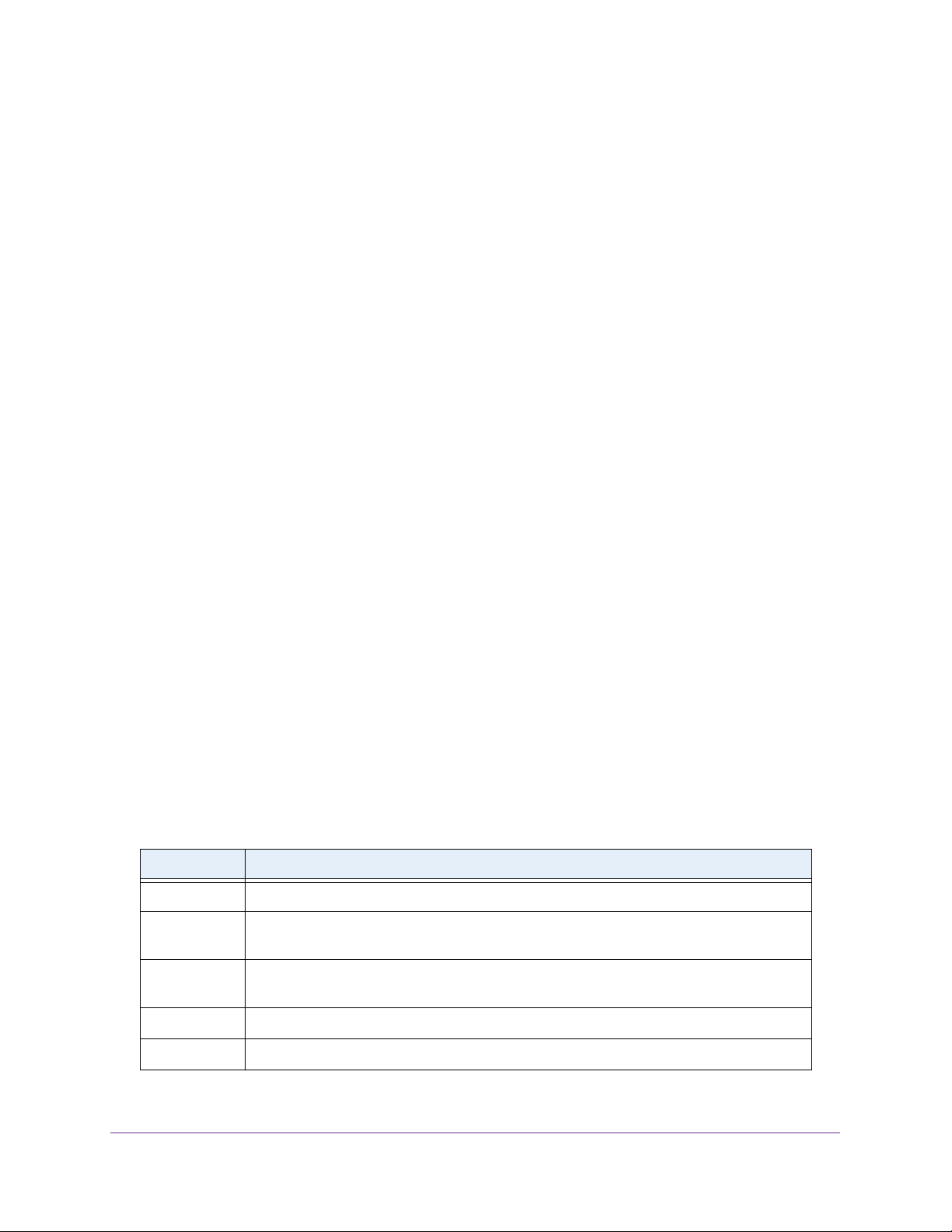
The following table shows the command buttons that are used on the pages in the local
browser interface:
Table 1. Local browser interface command buttons
Button Function
Add Clicking the Add button adds the new item configured in the heading row of a table.
Apply Clicking the Apply button sends the updated configuration to the switch. Configuration
changes take effect immediately.
Cancel Clicking the Cancel button cancels the configuration on the page and resets the data on
the page to the previous values of the switch.
Delete Clicking the Delete button removes the selected item.
Refresh Clicking the Refresh button refreshes the page with the latest information from the device.
Getting Started
20
Page 21

M4300 and M4300-96X Fully Managed Stackable Switches User Manual
Table 1. Local browser interface command buttons (continued)
Button Function
Save Clicking the Save button saves your settings.
Logout Clicking the Logout button ends the session.
IMPORTANT:
When you click the Apply button, your changes are saved for the
web management session but are not retained by the switch when it
is rebooted. You can manually save the configuration permanently
(see Save the Configuration on page 652) or you can enable the
automatic saving feature (see Configure Auto Save Mode on
page 652), which lets the switch save the configuration
permanently.
User-defined fields can contain 1 to 159 characters, unless otherwise noted on the
configuration web page. All characters can be used except for the following (unless
specifically noted in for that feature):
Table 2. Invalid characters for user-defined fields
\<
/>
*|
?
Interface Naming Conventions
The switch supports physical and logical interfaces. Interfaces are identified by their type and
the interface number. The physical ports are Gigabit Ethernet or multispeed 10G Ethernet
interfaces and are numbered on the front panel. You configure the logical interfaces by using
the software.
Getting Started
21
Page 22
M4300 and M4300-96X Fully Managed Stackable Switches User Manual
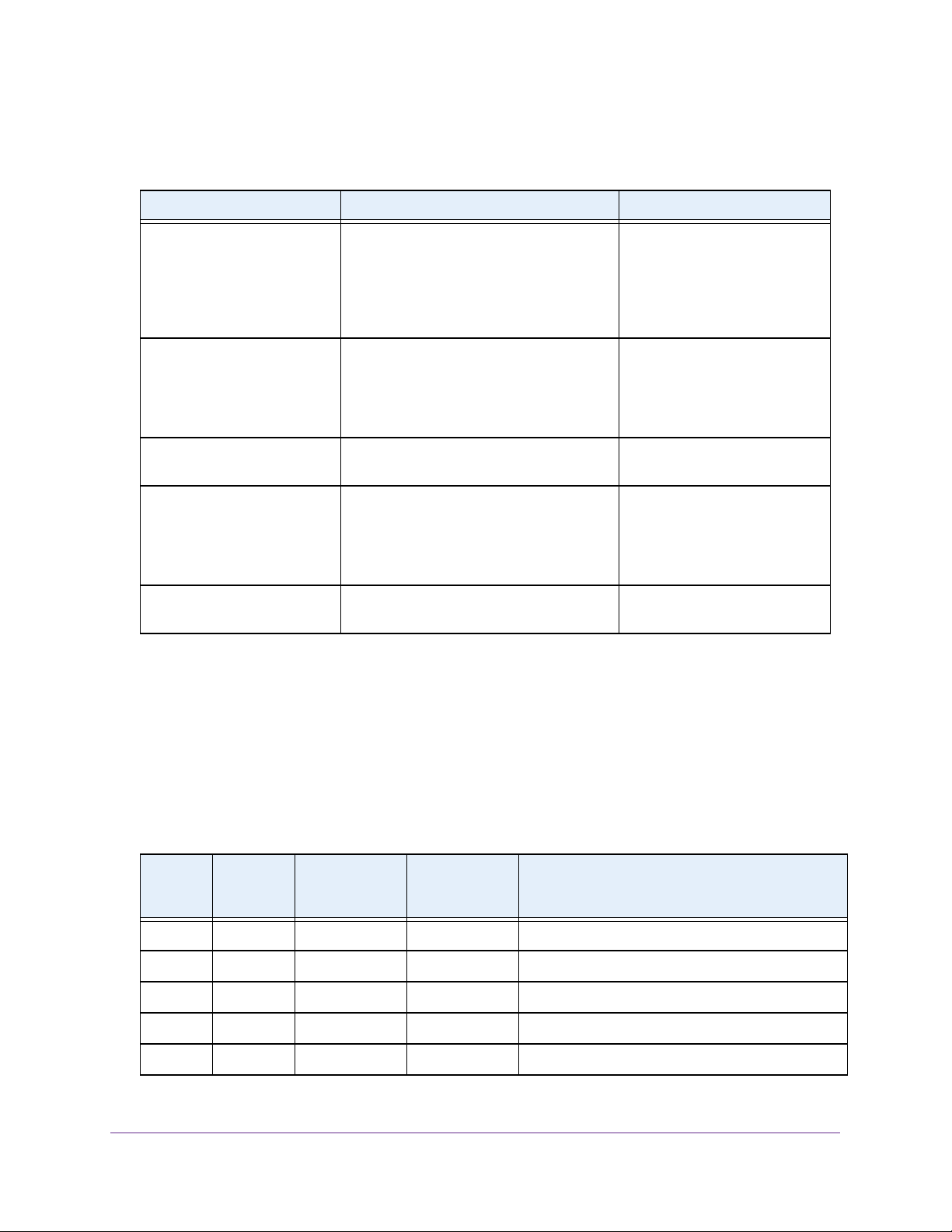
The following table describes the naming convention for all interfaces available on the switch.
Table 3. Naming conventions for interfaces
Interface Description Example
Physical interfaces for all
M4300 switch models except
for model M4300-96X
Physical interfaces for model
M4300-96X
Link aggregation group (LAG) LAG interfaces are logical interfaces that
CPU management interface This is the internal switch interface
Routing VLAN interfaces This is an interface used for routing
The physical ports are Gigabit Ethernet or
multispeed 10G Ethernet interfaces. The
interface number consists of the switch unit
number from 1 to 8, the slot number (which
is always 0), and the port number, which is
a sequential number starting from 1.
The physical ports are Gigabit Ethernet or
multispeed 10G Ethernet. The interface
number consists of the switch unit number
from 1 to 8, the port card number from 1 to
12, and the port number from 1 to 8.
are used only for bridging functions.
responsible for the switch base MAC
address. This interface is not configurable
and is always listed in the MAC Address
Table.
functionality.
1/0/1, 1/0/2, 1/0/3, and so on
2/0/1, 2/0/2, 2/0/3, and so on
3/0/1, 3/0/2, 3/0/3, and so on
See Slot and Port Numbering for
Switch Model M4300-96X on
page 22.
LAG 1, LAG 2, LAG 3, and so on
0/15/1
VLAN 1, VLAN 2, VLAN 3, and
so on
Slot and Port Numbering for Switch Model M4300-96X
For switch model M4300-96X, the slots in the upper row of the chassis are numbered 1
through 6 from left to right. These slots can support PoE. The slots in the lower row of the
chassis are numbered 7 through 12 from left to right. These slots do not support PoE.
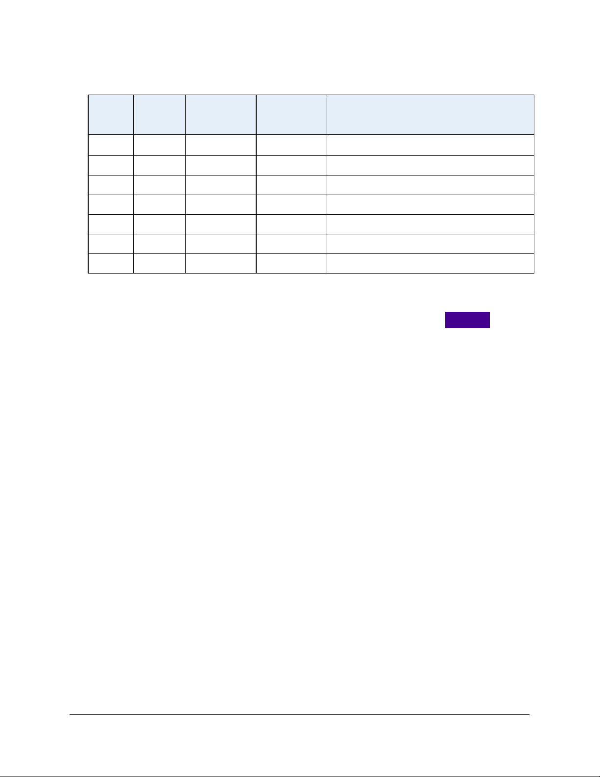
For the APM408C, APM408P, and APM408F port cards, the ports in the port cards in the
slots are numbered as described in the following table.
Table 4. Port numbering for the APM408C, APM408P, and APM408F port cards
Slot
Number
1 Upper row 1, 3, 5, 7 2, 4, 6, 8 1/1/1, 1/1/2, 1/1/3, and so on through 1/1/8
2 Upper row 1, 3, 5, 7 2, 4, 6, 8 1/2/1, 1/2/2, 1/2/3, and so on through 1/2/8
3 Upper row 1, 3, 5, 7 2, 4, 6, 8 1/3/1, 1/3/2, 1/3/3, and so on through 1/3/8
4 Upper row 1, 3, 5, 7 2, 4, 6, 8 1/4/1, 1/4/2, 1/4/3, and so on through 1/4/8
5 Upper row 1, 3, 5, 7 2, 4, 6, 8 1/5/1, 1/5/2, 1/5/3, and so on through 1/5/8
Slot
Location
Port Number
for Upper Ports
in Port Card
Port Number
for Lower Ports
in Port Card
Getting Started
Interface Convention
22
Page 23
M4300 and M4300-96X Fully Managed Stackable Switches User Manual
Table 4. Port numbering for the APM408C, APM408P, and APM408F port cards (continued)
Slot
Number
6 Upper row 1, 3, 5, 7 2, 4, 6, 8 1/6/1, 1/6/2, 1/6/3, and so on through 1/6/8
7 Lower row 1, 3, 5, 7 2, 4, 6, 8 1/7/1, 1/7/2, 1/7/3, and so on through 1/7/8
8 Lower row 1, 3, 5, 7 2, 4, 6, 8 1/8/1, 1/8/2, 1/8/3, and so on through 1/8/8
9 Lower row 1, 3, 5, 7 2, 4, 6, 8 1/9/1, 1/9/2, 1/9/3, and so on through 1/9/8
10 Lower row 1, 3, 5, 7 2, 4, 6, 8 1/10/1, 1/10/2, 1/10/3, and so on through 1/10/8
11 Lower row 1, 3, 5, 7 2, 4, 6, 8 1/11/1, 1/11/2, 1/11/3, and so on through 1/11/8
12 Lower row 1, 3, 5, 7 2, 4, 6, 8 1/12/1, 1/12/2, 1/12/3, and so on through 1/12/8
Slot
Location
Port Number
for Upper Ports
in Port Card
Port Number
for Lower Ports
in Port Card
Interface Convention
Online Help
When you log in to the switch, each page contains a link to the online help that
contains information to assist in configuring and managing the switch. The online help pop-up
windows are context sensitive. For example, if the IP Addressing page is open, the help topic
for that page displays if you click the Help button.
You can connect to the online support site at netgear.com when you are logged in to the
switch.
To access the online support link:
1. Launch a web browser.
2. In the address field of your web browser, enter the IP address of the switch.
The login window opens.
3. Enter the user name and password.
The default admin user name is admin and the default admin password is blank, that is,
do not enter a password.
4. Click the Login button.
The System Information page displays.
5. Select Help > Online Help > Support.
6. To connect to the NETGEAR support site for the M4300 and M4300-96X switches, click the
APPLY button.
Getting Started
23
Page 24
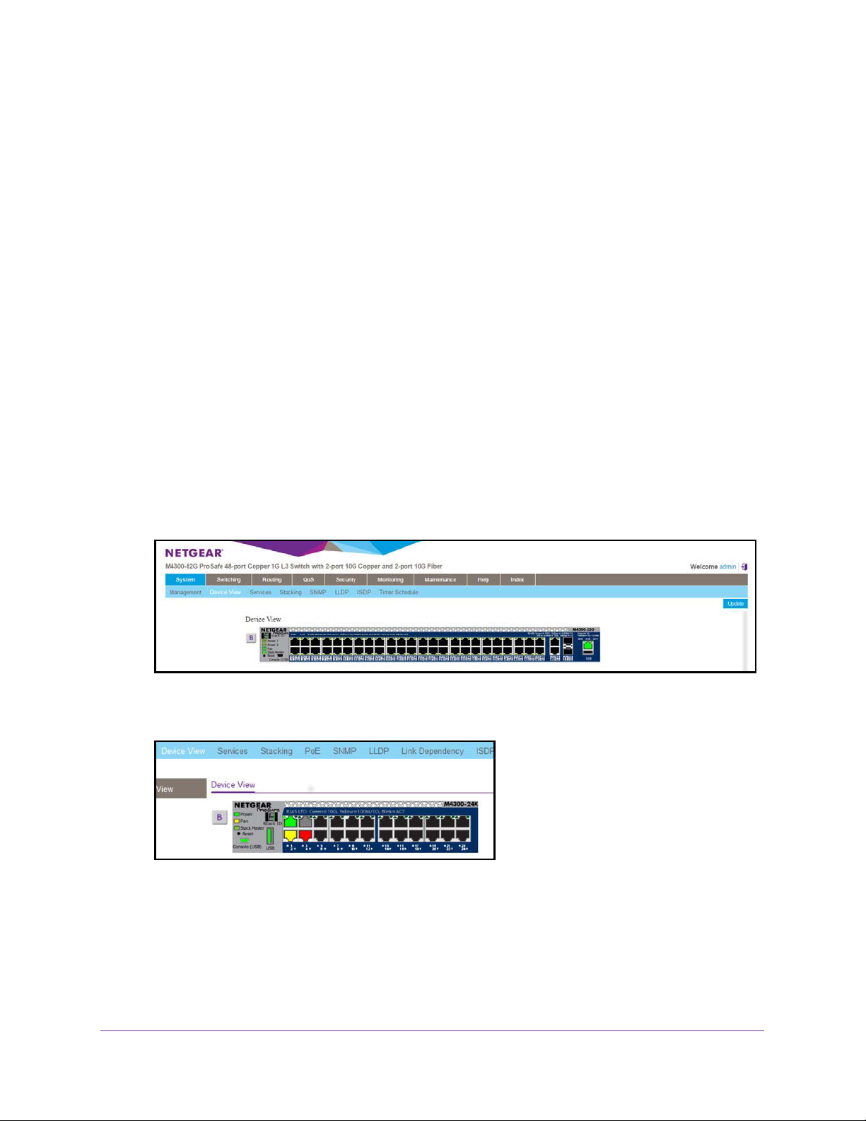
M4300 and M4300-96X Fully Managed Stackable Switches User Manual
Local Browser Interface Device View
The Device View is an HTML applet that displays the ports on the switch. This graphic
provides an alternate way to navigate to configuration and monitoring options. The graphic
also provides information about device ports, current configuration and status, tables, and
feature components.
To use Device View:
1. Launch a web browser.
2. In the address field of your web browser, enter the IP address of the switch.
The login window opens.
3. Enter the user name and password.
The default admin user name is admin and the default admin password is blank, that is,
do not enter a password.
4. Click the Login button.
The System Information page displays.
5. Select System > Device View.
As an example, the following figure shows the Device View page for model M4300-52G.
As another example, the following figure shows a close up of the Device View page for
model M4300-24X.
The port coloring indicates whether a port is currently active. Green indicates that the port
is enabled; red indicates that an error occurred on the port, or that the link is disabled.
6. Click a port to see a menu that displays statistics and configuration options.
You can click a menu option to access the page that contains the configuration or
monitoring options.
Getting Started
24
Page 25
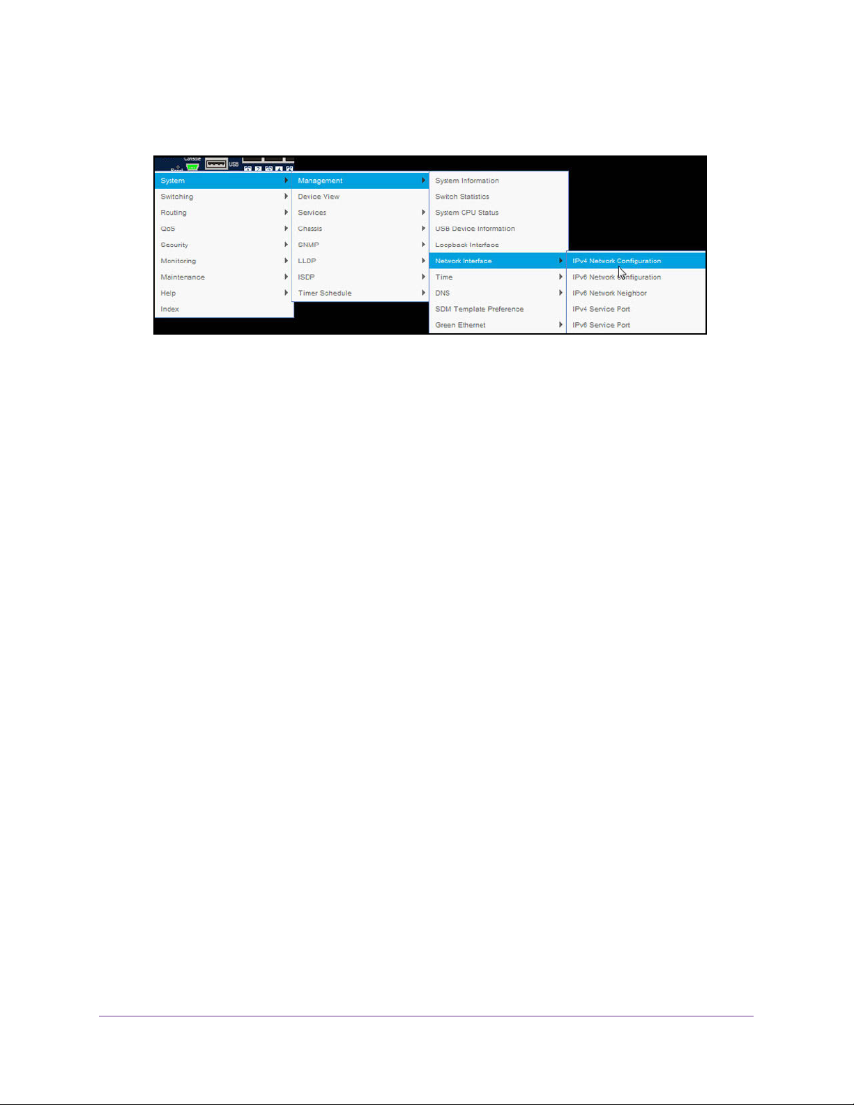
M4300 and M4300-96X Fully Managed Stackable Switches User Manual
If you click the graphic, but do not click a specific port, the main menu displays. This
menu contains the same options as the navigation tabs at the top of the page.
Using SNMP
The switch software supports the configuration of SNMP groups and users that can manage
traps that the SNMP agent generates.
The switch uses both standard public MIBs for standard functionality and private MIBs that
support additional switch functionality. All private MIBs begin with a “-” prefix. The main object
for interface configuration is in -SWITCHING-MIB, which is a private MIB. Some interface
configurations also involve objects in the public MIB, IF-MIB.
SNMP is enabled by default. The System Information page, which is the page that displays
when you log in, displays the information that you need to configure an SNMP manager to
access the switch.
Any user can connect to the switch using the SNMP v3 protocol, but for authentication and
encryption, the switch supports only one user, which is admin; therefore, only one profile can
be created or modified.
To configure authentication and encryption settings for the SNMP v3 admin profile:
1. Launch a web browser.
2. In the address field of your web browser, enter the IP address of the switch.
The login window opens.
3. Enter the user name and password.
The default admin user name is admin and the default admin password is blank, that is,
do not enter a password.
4. Click the Login button.
The System Information page displays.
5. Select System > SNMP > SNMP v3 > User Configuration.
The User Configuration page displays.
Getting Started
25
Page 26

M4300 and M4300-96X Fully Managed Stackable Switches User Manual
6. To enable authentication, select an Authentication Protocol option, which is either MD5 or
SHA.
7. To enable encryption, select the DES option in the Encryption Protocol list Then enter an
encryption code of eight or more alphanumeric characters in the Encryption Key field.
8. Click the APPLY button.
Your settings are saved.
Note: To access configuration information for SNMP V1 or SNMP V2, select
System > SNMP > SNMPv1/v2 and select the page that contains the
information that you want to configure.
Getting Started
26
Page 27

2. Configure System Information
This chapter covers the following topics:
• Initial Setup
• Time
• Configure DNS Settings
• Configure the Switch Database Management Template Preference
• Configure Green Ethernet Settings
• Configure DHCP Server Settings
• DHCP L2 Relay
• Manage the DHCPv6 Server
• Configure Power over Ethernet
• Configure SNMP
• Configure LLDP
2
• Configure Link Dependency
• Configure ISDP
• Timer Schedules
27
Page 28
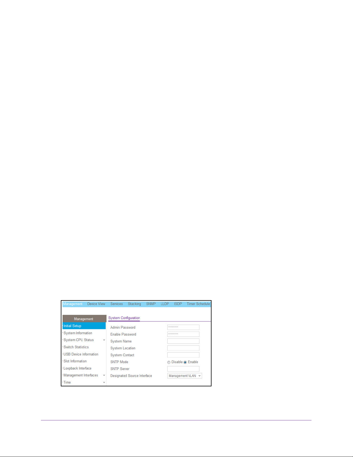
M4300 and M4300-96X Fully Managed Stackable Switches User Manual
Initial Setup
When you log in to a switch that has its factory settings, the Initial Setup page displays.
To perform the initial system configuration:
1. Prepare your computer with a static IP address:
• For access over an Ethernet network port, use a static IP address in the 169.254.0.0
subnet with subnet mask 255.255.0.0.
For example, use 169.254.100.201 for your computer.
• For access over the OOB port, use a static IP address in the 192.168.0.0 subnet with
subnet mask 255.255.0.0.
For example, use 192.168.0.201 for your computer.
2. Connect an Ethernet cable from an Ethernet port on your computer to either an Ethernet
network port on the switch or to the OOB port on the switch.
3. Launch a web browser such as Google Chrome, Mozilla Firefox, or Microsoft Internet
Explorer.
4. Enter the default IP address of the switch in the web browser address field:
• For access over an Ethernet network port, enter 169.254.100.100.
• For access over the OOB port, enter 192.168.0.239.
The login window opens.
5. Enter the user name and password.
The default admin user name is admin and the default admin password is blank, that is,
do not enter a password.
6. Click the Login button.
The local browser interface menu displays.
7. Select System > Management > Initial Setup.
8. Enter the new password for the Admin account in the Admin Password field.
Configure System Information
28
Page 29

M4300 and M4300-96X Fully Managed Stackable Switches User Manual
The new password does not display as you type it; only dots are shown to hide the entry.
The password is from 8 to 64 alphanumeric characters in length and is case-sensitive.
9. In the Enable Password field, enter the new password for the enable mode in the
command-line interface.
The new password does not display as you type it; only dots are shown to hide the entry.
The password is from 8 to 64 alphanumeric characters in length and is case-sensitive.
10. In the System Name field, type the name to identify this switch.
You can use a name up to 255 characters in length. The factory default is blank.
11. In the System Location field, type the location of the switch.
You can use a location up to 255 characters in length. The factory default is blank.
12. Enter the System Contact, the name of the contact person for this switch.
You can use a contact name up to 255 characters in length. The factory default is blank.
13. In the SNTP mode field, select Enable or Disable.
This specifies the state of the SNTP client. The default value is Disable, and the local
clock is used to get the time value.
14. Specify the address of the SNTP Server.
Enter a text string of up to 64 characters containing the host name of an SNTP server.
The server address can be IPv4, IPv6, or a host name. The host name resolves into an IP
address each time an SNTP request is sent to it.
15. In the Designated Source Interface list, select Management VLAN or Service Port.
This is the source interface that is used for SNMP trap, syslog, DNS, TACACS+,
RADIUS, sflow, and SNTP applications. By default, Management VLAN is used as the
source interface.
Note: If you select Management VLAN as the source interface, the routing
mode for the selected VLAN must be enabled.
16. Click the Apply button.
Your settings are saved.
Configure the Initial IPv4 Management VLAN
To configure the initial IPv4 management VLAN:
1. Launch a web browser.
2. In the address field of your web browser, enter the IP address of the switch.
The login window opens.
3. Enter the user name and password.
Configure System Information
29
Page 30
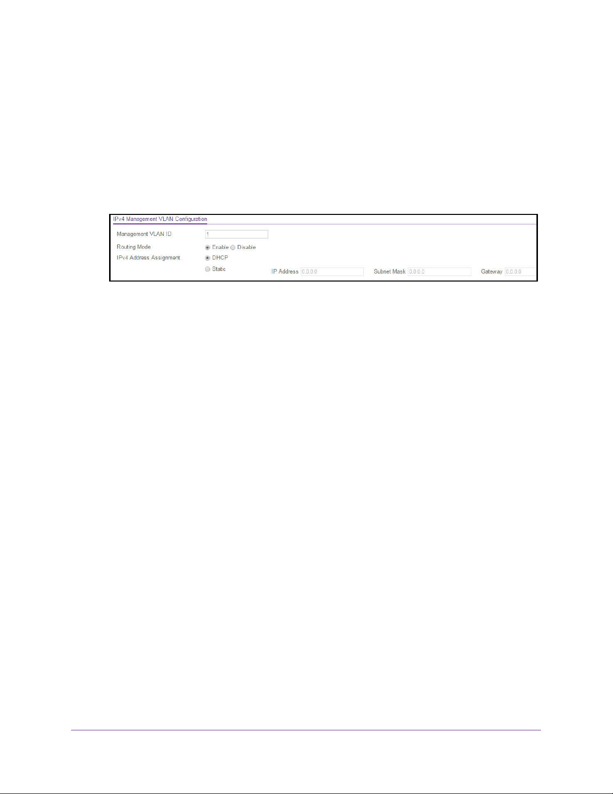
M4300 and M4300-96X Fully Managed Stackable Switches User Manual
The default admin user name is admin and the default admin password is blank, that is,
do not enter a password.
4. Click the Login button.
The System Information page displays.
5. Select System > Management > Initial Setup.
The Initial Setup page displays.
6. Scroll down to display the IPv4 Management VLAN Configuration section of the page.
7. Specify the Management VLAN ID of the switch.
The management VLAN is used for management of the switch. The VLAN ID can be any
value from 1 to 4093.
8. Select the radio button to Enable or Disable the global Routing Mode on the device.
The default is Enable.
9. Select the IPv4 Address Assignment DHCP or Static radio button.
This specifies the method for getting IPv4 network parameters (IPv4 address and network
mask) for the configured management VLAN interface. The default value for VLAN 1 is
Static.
10. In the IP Address field, specify the IP address of the management VLAN interface.
The factory default value is 169.254.100.100.
11. In the Subnet Mask field, specify the IP subnet mask for the management VLAN interface.
This is also referred to as the subnet/network mask and defines the portion of the
interface’s IP address that is used to identify the attached network. The factory default
value is 255.255.0.0.
12. In the Gateway field, specify the default gateway for the management VLAN interface.
The default value is 0.0.0.0.
13. Click the Apply button.
Your settings are saved.
Configure System Information
30
Page 31

M4300 and M4300-96X Fully Managed Stackable Switches User Manual
Configure the Initial IPv6 Management VLAN
For IPv6 management, you can use the same management VLAN that you use for IPv4
management or you can use a different VLAN. By default, the switch does not include an
IPv6 management VLAN and you must set it up manually if you want to use it.
To configure the initial IPv6 management VLAN:
1. Launch a web browser.
2. In the address field of your web browser, enter the IP address of the switch.
The login window opens.
3. Enter the user name and password.
The default admin user name is admin and the default admin password is blank, that is,
do not enter a password.
4. Click the Login button.
The System Information page displays.
5. Select System > Management > Initial Setup.
The Initial Setup page displays.
6. Scroll down to display the IPv6 Management VLAN Configuration section of the page.
7. Specify the Management VLAN ID of the switch.
The management VLAN is used for management of the switch. The VLAN ID can be any
value from 1 to 4093. There is no IPv6 management interface configured by default.
8. Select an IPv6 Address Assignment radio button.
This specifies the method for getting IPv6 network parameters (IPv6 prefix and prefix
length) for the configured management VLAN interface. The possible options are
DHCPv6, Auto Config, or Static. The default value for VLAN 1 is Auto Config.
9. In the IPv6 Prefix and Prefix Length field, specify the IPv6 prefix and prefix length for the
management VLAN interface.
When Auto Config is selected, the appropriate IPv6 prefix and prefix length is displayed
in this field.
10. In the IPv6 Gateway field, specify the default IPv6 gateway for the management VLAN
interface.
11. Click the Apply button.
Your settings are saved.
Configure System Information
31
Page 32

M4300 and M4300-96X Fully Managed Stackable Switches User Manual
Configure the Initial Service Port Settings
To perform the initial service port configuration:
1. Launch a web browser.
2. In the address field of your web browser, enter the IP address of the switch.
The login window opens.
3. Enter the user name and password.
The default admin user name is admin and the default admin password is blank, that is,
do not enter a password.
4. Click the Login button.
The System Information page displays.
5. Click System > Management > Initial Setup.
The Initial Setup page displays.
6. Scroll down to the bottom of the page to display the Service Port Configuration section.
7. Select an IPv4 Address Assignment radio button.
This specifies the method for getting IPv4 network parameters (IPv4 address and network
mask) for the service port. Possible options are DHCP, BootP, or Static. The default
value is Static.
8. Specify the IP Address for the service port.
The factory default value is 192.168.0.239.
9. Specify the Subnet Mask for the service port.
This is also referred to as the subnet/network mask and defines the portion of the
interface’s IP address that is used to identify the attached network. The factory default
value is 255.255.255.0.
10. Specify the default Gateway for the service port.
The default value is 0.0.0.0.
11. In the IPv6 Address Assignment field, select the method for getting IPv6 network
parameters (IPv6 prefix and prefix length) for the configured service port.
Possible options are DHCPv6, Auto Config, or Static. The default value is Auto Config.
12. Specify the IPv6 Prefix and Prefix Length for the service port.
Configure System Information
32
Page 33

M4300 and M4300-96X Fully Managed Stackable Switches User Manual
When Auto Config is selected, the appropriate IPv6 prefix and prefix length are displayed
in this field.
13. Specify the default IPv6 Gateway for the service port.
14. Click the Apply button.
Your settings are saved.
View or Define System Information
When you log in, the System Information page displays. You can configure and view general
device information.
To view or define system information:
1. Launch a web browser.
2. In the address field of your web browser, enter the IP address of the switch.
The login window opens.
3. Enter the user name and password.
The default admin user name is admin and the default admin password is blank, that is,
do not enter a password.
4. Click the Login button.
The System Information page displays.
5. Select System > Management > System Information.
6. Define the following fields:
• System Name. Enter the name to identify this switch. You can use up to 255
alphanumeric characters. The factory default is blank.
• System Location. Enter the location of this switch. You can use up to 255
alphanumeric characters. The factory default is blank.
Configure System Information
33
Page 34

M4300 and M4300-96X Fully Managed Stackable Switches User Manual
• System Contact. Enter the contact person for this switch. You can use up to 255
alphanumeric characters. The factory default is blank.
• Login Timeout. Specify how many minutes of inactivity can occur on a serial port
connection before the switch closes the connection. Enter a number between 0 and
160 minutes. The factory default is 5. Entering 0 disables the time-out.
• Management Source Interface. Select the management interface that is used as
source interface for SNMP trap, syslog, DNS, TACACS+, RADIUS, sflow, and SNTP
applications. Possible values are as follows:
- None
- Routing Interface
- Routing VLAN
- Routing Loopback Interface
- Service Port
- Different. For some applications from the list, the source interface is configured
separately. They display in the list only if this is the case.
By default VLAN 1 is used as the source interface.
7. Click the Apply button.
Your settings are saved.
The following table describes the status information the System Information page displays.
Table 5. System Information
Field Description
Product Name The product name of this switch.
IPv4 Management Address The IPv4 address and mask assigned to the management VLAN
interface.
IPv6 Management Address The IPv6 address and mask assigned to the management VLAN
interface.
IPv4 Management Interface The IPv4 management VLAN ID of the switch. Click the displayed
Management VLAN ID value to jump to the configuration page. See
Configure an IPv4 Management VLAN on page 52.
IPv6 Management Interface The IPv6 management VLAN ID of the switch. Click the displayed
Management VLAN ID value to jump to the configuration page. See
Configure an IPv6 Management VLAN on page 54.
IPv4 Loopback Interface The IPv4 address and mask assigned to the loopback interface.
IPv6 Loopback Interface The IPv6 prefix and prefix length assigned to the loopback interface.
System Date The current date.
Current SNTP Sync Status The current SNTP sync status.
System SNMP OID The base object ID for the switch's enterprise MIB.
Configure System Information
34
Page 35

M4300 and M4300-96X Fully Managed Stackable Switches User Manual
Table 5. System Information (continued)
Field Description
System Mac Address Universally assigned network address.
Service Port MAC Address The MAC address used for out-of-band connectivity.
L2 MAC Address The MAC address used for communications on the Layer 2 network
segment.
L3 MAC Address The MAC address used for communications on the Layer 3 network
segment.
Current SNTP Synchronized Time The SNTP synchronized time.
View the Fan Status
This page shows the status of the fans in all units. These fans remove the heat generated by
the power, CP,U and other chipsets, and allow the chipsets work normally. Fan status has
three possible values: OK, Failure, and Not Present.
To view the fan status:
1. Launch a web browser.
2. In the address field of your web browser, enter the IP address of the switch.
The login window opens.
3. Enter the user name and password.
The default admin user name is admin and the default admin password is blank, that is,
do not enter a password.
4. Click the Login button.
The System Information page displays.
5. Select Management > System Information > Fan Status.
6. To refresh the page, click the Update button.
Configure System Information
35
Page 36

M4300 and M4300-96X Fully Managed Stackable Switches User Manual
The following table describes the nonconfigurable Fan Status information.
Table 6. Fan Status
Field Description
Unit ID The unit ID of the switch to which the fan belongs.
System-1 The working status of the System-1 fan in each unit.
System-2 The working status of the System-2 fan in each unit.
System-3 The working status of the System-3 fan in each unit.
View the Temperature Sensor Information
You can view the current temperature of different system sensors using the Temperature
Status table. The temperature is instant and can be refreshed with the latest information on
the switch when the Update button is clicked. The maximum temperature of the CPU and
MACs depends on the actual hardware.
To view temperature information:
1. Launch a web browser.
2. In the address field of your web browser, enter the IP address of the switch.
The login window opens.
3. Enter the user name and password.
The default admin user name is admin and the default admin password is blank, that is,
do not enter a password.
4. Click the Login button.
The System Information page displays.
5. Select System > Management > System Information > Temperature Sensors.
6. To refresh the page, click the Update button.
Configure System Information
36
Page 37

M4300 and M4300-96X Fully Managed Stackable Switches User Manual
The following table describes the nonconfigurable Temperature Status information.
Table 7. Temperature Status information
Field Description
Unit ID The unit number in the switch.
MAC-A The current temperature (in degrees Centigrade) of the MAC-A sensor
of the switch. The maximum is 31°C.
MAC-B The current temperature (in degrees Centigrade) of the MAC-B sensor
of the switch. The maximum is 37°C.
System The current temperature (in degrees Centigrade) of the System sensor
of the switch. The maximum is 31°C.
View the Device Status
This page shows the software version of each device.
To view the device status:
1. Launch a web browser.
2. In the address field of your web browser, enter the IP address of the switch.
The login window opens.
3. Enter the user name and password.
The default admin user name is admin and the default admin password is blank, that is,
do not enter a password.
4. Click the Login button.
The System Information page displays.
5. Select Management > System Information > Device Status.
6. To refresh the page, click the Update button.
Configure System Information
37
Page 38

M4300 and M4300-96X Fully Managed Stackable Switches User Manual
The following table describes the nonconfigurable Device Status information.
Table 8. Device Status
Field Description
Unit ID The unit number in the switch.
Firmware Version The release.version.maintenance number of the code currently running
on the switch. For example, if the release was 1, the version was 2, and
the maintenance number was 4, the format would be 1.2.4.
Boot Version The version of the boot code that is in the flash memory to load the
firmware into the memory.
CPLD Version The version of the software for CPLD.
Serial Number The serial number of this switch.
Internal AC-1, Internal AC-2, and
so on
System Up Time The time in days, hours, and minutes since the last switch reboot.
Indicates the status of the appropriate power module in each unit.
Status can be any of the following:
• Operational. Power module is present and functioning properly.
• Powering. Main power is failed or disconnected but RPS provides
power to the switch.
• Not Present. Power module is not present in the slot.
• Not powered. Power module is present but not connected to the
power source.
• Not powering. Power module is present and connected but the
switch uses another power source.
• Incompatible. Power module is present but incompatible.
• Failed. Power module is present, but power cable is not plugged in
or a bad cable is plugged in.
View the System CPU Status
To view the system CPU status:
1. Launch a web browser.
2. In the address field of your web browser, enter the IP address of the switch.
The login window opens.
3. Enter the user name and password.
The default admin user name is admin and the default admin password is blank, that is,
do not enter a password.
4. Click the Login button.
The System Information page displays.
5. Select System > Management > System CPU Status.
Configure System Information
38
Page 39

M4300 and M4300-96X Fully Managed Stackable Switches User Manual
6. You can view the CPU Utilization information, which contains the memory information,
task-related information, and percentage of CPU utilization per task.
• Select the Unit No. to display the CPU Utilization information.
• Select All to display the CPU Utilization information for all units in a switch.
The following table describes CPU Memory Status information.
Table 9. CPU Memory Status information
Field Description
Total System Memory The total memory of the switch in KBytes.
Available Memory The available memory space for the switch in KBytes.
Configure the CPU Thresholds
The CPU Utilization Threshold notification feature allows you to configure thresholds that,
when crossed, trigger a notification. The notification is done through SNMP trap and syslog
messages.
To configure the CPU thresholds:
1. Launch a web browser.
2. In the address field of your web browser, enter the IP address of the switch.
The login window opens.
3. Enter the user name and password.
Configure System Information
39
Page 40

M4300 and M4300-96X Fully Managed Stackable Switches User Manual
The default admin user name is admin and the default admin password is blank, that is,
do not enter a password.
4. Click the Login button.
The System Information page displays.
5. Select System > Management > System CPU Status > CPU Threshold.
6. Configure the Rising Threshold value.
Notification is generated when the total CPU utilization exceeds this threshold value over
the configured time period. The range is 1 to 100.
7. Configure the Rising Interval value.
This utilization monitoring time period can be configured from 5 to 86400 seconds in
multiples of 5 seconds.
8. Configure the Falling Threshold.
Notification is triggered when the total CPU utilization falls below this level for a
configured period of time.
The falling utilization threshold must be equal to or less than the rising threshold value.
The falling utilization threshold notification is made only if a rising threshold notification
was done previously. Configuring the falling utilization threshold and time period is
optional. If the Falling CPU utilization parameters are not configured, then it takes the
same value as Rising CPU utilization parameters. The range is 1 to 100.
9. Configure the Falling Interval.
The utilization monitoring time period can be configured from 5 seconds to 86400
seconds in multiples of 5 seconds.
10. Configure the CPU Free Memory Threshold value in KB.
11. Click the Apply button.
Your settings are saved.
Configure System Information
40
Page 41

M4300 and M4300-96X Fully Managed Stackable Switches User Manual
View and Clear Switch Statistics
To view and clear the switch statistics:
1. Launch a web browser.
2. In the address field of your web browser, enter the IP address of the switch.
The login window opens.
3. Enter the user name and password.
The default admin user name is admin and the default admin password is blank, that is,
do not enter a password.
4. Click the Login button.
The System Information page displays.
5. Select System > Management > Switch Statistics.
6. To clear all the counters, resetting all switch summary and detailed statistics to default
values, click the Clear button.
The discarded packets count cannot be cleared.
Configure System Information
41
Page 42

M4300 and M4300-96X Fully Managed Stackable Switches User Manual
The following table describes Switch Statistics information.
Table 10. Switch Statistics information
Field Description
ifIndex The ifIndex of the interface table entry associated with the processor of
this switch.
Octets Received The total number of octets of data received by the processor (excluding
framing bits but including FCS octets).
Packets Received Without Errors The total number of packets (including broadcast packets and multicast
packets) received by the processor.
Unicast Packets Received The number of subnetwork-unicast packets delivered to a higher-layer
protocol.
Multicast Packets Received The total number of packets received that were directed to a multicast
address. This number does not include packets directed to the
broadcast address.
Broadcast Packets Received The total number of packets received that were directed to the
broadcast address. This does not include multicast packets.
Receive Packets Discarded The number of inbound packets that were discarded even though no
errors were detected to prevent their being deliverable to a higher-layer
protocol. A possible reason for discarding a packet could be to free up
buffer space.
Octets Transmitted The total number of octets transmitted out of the interface, including
framing characters.
Packets Transmitted Without Errors The total number of packets transmitted out of the interface.
Unicast Packets Transmitted The total number of packets that higher-level protocols requested that
are transmitted to a subnetwork-unicast address, including those that
were discarded or not sent.
Multicast Packets Transmitted The total number of packets that higher-level protocols requested that
are transmitted to a multicast address, including those that were
discarded or not sent.
Broadcast Packets Transmitted The total number of packets that higher-level protocols requested that
are transmitted to the broadcast address, including those that were
discarded or not sent.
Transmit Packets Discarded The number of outbound packets that were discarded even though no
errors were detected to prevent their being deliverable to a higher-layer
protocol. A possible reason for discarding a packet could be to free up
buffer space.
Most Address Entries Ever Used The highest number of Forwarding Database Address Table entries
learned by this switch since the most recent reboot.
Address Entries in Use The number of learned and static entries in the Forwarding Database
Address Table for this switch.
Maximum VLAN Entries The maximum number of virtual LANs (VLANs) allowed on this switch.
Configure System Information
42
Page 43

M4300 and M4300-96X Fully Managed Stackable Switches User Manual
Table 10. Switch Statistics information (continued)
Field Description
Most VLAN Entries Ever Used The largest number of VLANs that were active on this switch since the
last reboot.
Static VLAN Entries The number of presently active VLAN entries on this switch that were
created statically.
Dynamic VLAN Entries The number of presently active VLAN entries on this switch that were
created by GVRP registration.
VLAN Deletes The number of VLANs on this switch that were created and then deleted
since the last reboot.
Time Since Counters Last Cleared The elapsed time, in days, hours, minutes, and seconds, since the
statistics for this switch were last cleared.
View USB Device Information
To display the USB device information:
1. Launch a web browser.
2. In the address field of your web browser, enter the IP address of the switch.
The login window opens.
3. Enter the user name and password.
The default admin user name is admin and the default admin password is blank, that is,
do not enter a password.
4. Click the Login button.
The System Information page displays.
5. Select System > Management > USB Device Information.
The Device Status field displays the current status of the device. The status is one of the
following:
• Active. The device is USB plugged in and recognized by the switch.
Configure System Information
43
Page 44

M4300 and M4300-96X Fully Managed Stackable Switches User Manual
• Inactive. The device is not mounted.
• Invalid. The device is not present or an invalid device is plugged in.
6. To refresh the page, click the Update button.
The following table describes the USB Memory Statistics information.
Table 11. USB Memory Statistics information
Field Description
Total Size The USB flash device storage size in bytes.
Bytes Used The size of memory used on the USB flash device.
Bytes Free The size of memory free on the USB flash device.
The following table describes the USB Directory Details information.
Table 12. USB Directory Details information
Field Description
File Name The name of the file stored in the USB flash drive.
File Size The size of the file stored in the USB flash drive in bytes
Modification Time The last modification time of the file stored in the USB flash drive.
Configure and View Information About Slots and Port Cards
You can configure information about the port cards that are installed in the switch’s slots and
view information about the port cards and other switches that are compatible with the switch.
To configure and view information about slots and port cards:
1. Launch a web browser.
2. In the address field of your web browser, enter the IP address of the switch.
The login window opens.
3. Enter the user name and password.
The default admin user name is admin and the default admin password is blank, that is,
do not enter a password.
4. Click the Login button.
The System Information page displays.
5. Select System > Management > Slot Information.
Configure System Information
44
Page 45

M4300 and M4300-96X Fully Managed Stackable Switches User Manual
6. For model M4300-96X only, from the Administrative State menu, select Enable or
Disable.
By default, all slots are enabled, but you can select to disable a slot.
7. For model M4300-96X only, from the Power State menu, select Enable or Disable.
By default, the switch provides power to all slots, but you can select to prevent the switch
from providing power to a slot.
8. For model M4300-96X, if you changed the settings, click the Apply button.
Your settings are saved.
The following table describes information in the Slot Configuration table.
Field Description
Slot The unit and slot number.
Status Indicates whether the slot is empty or full.
Configured Card Model ID The model ID of the port card configured for the slot.
Configured Card Description The description of the port card configured for the slot
Inserted Card Model ID The model ID of the port card plugged into the slot.
Inserted Card Description The description of the port card plugged into the slot.
Card Power Down If the value is True, the power state can be administratively enabled or
disabled. If the value is False, the power state cannot be configured.
Card Pluggable If the value is True, the card can be administratively enabled or disabled. If
the value is False, the administrative state cannot be configured.
PoE Capable Indicates whether a port card is PoE cable.
Configure System Information
45
Page 46

M4300 and M4300-96X Fully Managed Stackable Switches User Manual
The following table describes information in the Supported Card table.
Field Description
Card Model The model ID of the supported port card.
Card Index The index assigned to the port card type.
Card Type The hardware type of the supported port card, which is assigned by the
manufacturer.
Card Descriptor The description of the supported port card, which includes the manufacturer
product number and information about the number and speed of the
supported interfaces.
The following table describes information in the Supported Switch table. If you
preconfigure a new stack member, the switch index identifies the type of switch that is
being added to the stack.
Field Description
Switch Model ID The model number of the supported switch.
Switch Index The index that is assigned to the supported switch.
Management Preference The management preference of the supported switch.
Configure System Information
46
Page 47

M4300 and M4300-96X Fully Managed Stackable Switches User Manual
Configure a Loopback Interface
You can create, configure, and remove loopback interfaces.
To configure a loopback interface:
1. Launch a web browser.
2. In the address field of your web browser, enter the IP address of the switch.
The login window opens.
3. Enter the user name and password.
The default admin user name is admin and the default admin password is blank, that is,
do not enter a password.
4. Click the Login button.
The System Information page displays.
5. Select System > Management > Loopback Interface.
6. Use the Loopback Interface Type list to select IPv4 or IPv6 loopback interface.
7. In the Loopback ID list, select a list of currently configured loopback interfaces.
8. In the Primary IP Address field, enter the primary address for this interface in
dotted-decimal notation.
This option is visible when IPv4 loopback is selected.
9. In the Primary IP Subnet Mask field, enter the primary IPv4 subnet mask in dotted-decimal
notation.
This option is visible when IPv4 loopback is selected.
10. In the Secondary IP Address field, enter the secondary IP address in dotted-decimal
notation.
This input field is visible only when Add Secondary is selected. This option is visible
when IPv4 loopback is selected.
Configure System Information
47
Page 48

M4300 and M4300-96X Fully Managed Stackable Switches User Manual
11. In the Secondary Subnet Mask field, enter the secondary subnet mask for this interface in
dotted-decimal notation.
This input field is visible only when Add Secondary is selected. This option is visible
when IPv4 loopback is selected.
12. In the IPv6 mode field, enable IPv6 on this interface using the IPv6 address.
This option is configurable before you specify an explicit IPv6 address. This option is
visible when IPv6 loopback is selected.
13. Use the IPv6 Address field to enter the IPv6 address in the format prefix/length.
This option is visible when IPv6 loopback is selected.
14. Use the EUI64 field to optionally specify the 64-bit extended unique identifier (EUI-64).
This option is visible when IPv6 loopback is selected.
15. Click the Apply button.
Your settings are saved.
Configure Management Interfaces
The local browser interface includes separate options for interface and port-based IP
management. Port-based IP management disables VLAN-based (default/existing) IP
management once you configure the port-based IP management and vice versa.
The source interface for applications is set to VLAN 1 by default. Changes in IPv4
Management VLAN and port to a non-default value also sets the source interface to the
VLAN 1 default VLAN/port automatically.
Configure the IPv4 Service Port
You can configure network information on the IPv4 service port. The service port is a
dedicated Ethernet port for out-of-band management of the device. Traffic on this port is
segregated from operational network traffic on the switch ports and cannot be switched or
routed to the operational network.
To configure the IPv4 service port:
1. Launch a web browser.
2. In the address field of your web browser, enter the IP address of the switch.
The login window opens.
3. Enter the user name and password.
The default admin user name is admin and the default admin password is blank, that is,
do not enter a password.
4. Click the Login button.
The System Information page displays.
Configure System Information
48
Page 49

M4300 and M4300-96X Fully Managed Stackable Switches User Manual
5. Select System > Management > Management Interfaces > IPv4 Service Port
Configuration.
6. Select a Service Port Configuration Protocol radio button:
• BootP. During the next boot cycle, the BootP client on the device broadcasts a BootP
request in an attempt to acquire information from a BootP server on the network.
• DHCP. During the next boot cycle, the DHCP client on the device broadcasts a DHCP
request in an attempt to acquire information from a DHCP server on the network.
• None. The device does not attempt to acquire network information dynamically.
• This specifies how the device acquires network information on the service port.
7. In the IP Address field, specify the IP address of the interface.
• If the service port configuration protocol is None, you can manually configure a static
IP address.
• If the service port configuration protocol is BootP or DHCP, this field displays the IP
address that was dynamically acquired (if any).
8. In the Subnet Mask field, specify the IP subnet mask for the interface:
• If the service port configuration protocol is None, you can manually configure a static
subnet mask.
• If the service port configuration protocol is BootP or DHCP, this field displays the
subnet mask that was dynamically acquired (if any).
9. In the Default Gateway field, specify the default gateway for the IP interface:
• If the Service Port Configuration Protocol is None, you can manually configure the IP
address of the default gateway.
• If the Service Port Configuration Protocol is BootP or DHCP, this field displays the
default gateway address that was dynamically acquired (if any).
10. Click the Apply button.
Your settings are saved.
Configure System Information
49
Page 50

M4300 and M4300-96X Fully Managed Stackable Switches User Manual
The following table describes the nonconfigurable fields on the Service Port Configuration
page.
Table 13. IPv4 Service Port Configuration
Field Description
Burned-in MAC Address The burned-in MAC address used for out-of-band connectivity.
Interface Status Indicates whether the link status is up or down.
Configure the IPv6 Service Port
You can configure IPv6 network information on the service port. The service port is a
dedicated Ethernet port for out-of-band management of the device. Traffic on this port is
segregated from operational network traffic on the switch ports and cannot be switched or
routed to the operational network.
To configure the IPv6 service port:
1. Launch a web browser.
2. In the address field of your web browser, enter the IP address of the switch.
The login window opens.
3. Enter the user name and password.
The default admin user name is admin and the default admin password is blank, that is,
do not enter a password.
4. Click the Login button.
The System Information page displays.
5. Select System > Management > Management Interfaces > IPv6 Service Port
Configuration.
Configure System Information
50
Page 51

M4300 and M4300-96X Fully Managed Stackable Switches User Manual
6. Select the IPv6 mode Enable or Disable radio button.
This specifies the IPv6 administrative mode on the service port.
7. Select the Service Port Configuration Protocol None or DHCP radio button.
This specifies whether the device acquires network information from a DHCPv6 server.
Selecting None disables the DHCPv6 client on the service port.
8. Select the IPv6 Stateless Address AutoConfig mode Enable or Disable radio button:
• Enable. The service port can acquire an IPv6 address through IPv6 Neighbor
Discovery Protocol (NDP) and through the use of router advertisement messages.
• Disable. The service port does not use the native IPv6 address autoconfiguration
feature to acquire an IPv6 address.
This sets the IPv6 stateless address autoconfiguration mode on the service port.
9. The DHCPv6 Client DUID field displays the client identifier used by the DHCPv6 client (if
enabled) when sending messages to the DHCPv6 server.
10. To configure the IPv6 gateway, select the Change IPv6 Gateway check box.
The IPv6 gateway is the default gateway for the IPv6 service port interface.
11. Use the IPv6 Gateway field to specify the default gateway for the IPv6 service port
interface.
The Add/Delete IPv6 Address table lists the manually configured static IPv6 addresses
on the service port interface.
12. Specify the following:
a. In the IPv6 Address field, specify the IPv6 address to add or remove from the service
port interface.
Configure System Information
51
Page 52

M4300 and M4300-96X Fully Managed Stackable Switches User Manual
b. Select the EUI Flag option to enable the Extended Universal Identifier (EUI) flag for
IPv6 address, or clear the option to omit the flag.
13. Click the Add button.
The IPv6 address is added to the service port interface.
14. Click the Apply button.
Your settings are saved.
Management VLAN Overview
For you to manage the device by using the web-based configuration utility, the device
management IP address must be defined and known. A management VLAN interface is
created by default and it gets an IP address if a DHCP server is present. If it fails to get an IP
address, a fallback address 169.254.100.100/255.255.0.0 is assigned to it. Management
VLAN is used as the default source interface for syslog, message log, and SNMP client, and
so on The network interface is disabled by default.
The management VLAN is the logical interface used for in-band connectivity with the switch
through any of the switch’s front panel ports. The configuration parameters associated with
the switch’s management VLAN do not affect the configuration of the front panel ports
through which traffic is switched or routed.
To access the switch over a network, you must first configure it with IP information (IP
address, subnet mask). You can configure the IP information using any of the following:
• DHCP
• Terminal interface through the EIA-232 port
After you establish in-band connectivity, you can change the IP information using any of the
following:
• Terminal interface through the EIA-232 port
• Terminal interface through Telnet
• SNMP-based management
• Web-based management
Configure an IPv4 Management VLAN
To configure an IPv4 Management VLAN:
1. Launch a web browser.
2. In the address field of your web browser, enter the IP address of the switch.
The login window opens.
3. Enter the user name and password.
The default admin user name is admin and the default admin password is blank, that is,
do not enter a password.
Configure System Information
52
Page 53

M4300 and M4300-96X Fully Managed Stackable Switches User Manual
4. Click the Login button.
The System Information page displays.
5. Select System > Management > Management Interfaces > IPv4 Management VLAN
Configuration.
6. In the Management VLAN ID field, specify the Management VLAN ID of the switch. The
management VLAN is used for management of the switch. It can be configured to any value
in the range of 1–4093.
7. Select the Routing Mode radio button to Enable or Disable the global routing on the
device. The default value is Enable.
8. Select the Configuration Method DHCP or Manual radio button:
• DHCP. Transmit a DHCP request.
• Manual. Do nothing.
This specifies what the switch does on start-up.
9. Specify the IP Address of the interface.
The factory default value is 169.254.100.100.
10. Specify the IP Subnet Mask for the interface. This is also referred to as the subnet/network
mask and defines the portion of the interface’s IP address that is used to identify the
attached network.
The factory default value is 255.255.0.0.
11. Specify the Gateway for the management VLAN interface.
The factory default value is 0.0.0.0.
12. In the Reset IPv4 Management Interface section of the page, use the Set Management
Interface to Default option to set the IPv4 management interface to the default VLAN 1.
13. Click the Apply button.
Your settings are saved.
Configure System Information
53
Page 54

M4300 and M4300-96X Fully Managed Stackable Switches User Manual
The Current IPv4 Management Interface Status is displayed at the bottom of the page.
The table below describes the nonconfigurable fields.
Table 14. Nonconfigurable IPv4 Management Interface Status
Field Description
Management Interface Displays the current IPv4 management interface
Link State Indicates whether the link status is up or down.
Routing Interface Status Indicates whether the link status is up or down for the management
interface.
MAC Address The MAC address assigned to the management interface.
IP Address Configuration Method Indicates whether the IP address configuration method is DHCP or
manual.
IP Address The IP address of the management interface.
Subnet Mask The IP subnet mask for the management interface.
Gateway The specified default gateway for the management interface.
Configure an IPv6 Management VLAN
To configure IPv6 Management, you have the choice to configure IPv6 Management using
the same VLAN as is used for IPv4 Management or using a different VLAN. IPv6
Management configuration is non-default and you need to create it manually.
To configure an IPv6 management VLAN:
1. Launch a web browser.
2. In the address field of your web browser, enter the IP address of the switch.
The login window opens.
Configure System Information
54
Page 55

M4300 and M4300-96X Fully Managed Stackable Switches User Manual
3. Enter the user name and password.
The default admin user name is admin and the default admin password is blank, that is,
do not enter a password.
4. Click the Login button.
The System Information page displays.
5. Select System > Management > Management Interfaces > IPv6 Management VLAN
Configuration.
6. In the Management VLAN ID field, specify the Management VLAN ID of the switch. The
management VLAN is used for management of the switch. The VLAN ID can be any value
from 1 to 4093. There is no IPv6 management interface configured by default.
7. Select the IPv6 Enable Mode radio button to Enable or Disable the administration mode
for the management VLAN IPv6 interface on the switch.
8. Select the radio button to Enable or Disable Address Autoconfigure Mode. If you select
Enable, the IPv6 network parameters (IPv6 prefix and prefix length) are autoconfigured for
the configured management VLAN interface. The default value for VLAN 1 is Auto Config.
Note: The Address Autoconfigure mode option is available only if unicast
routing is globally disabled.
9. Select the Address DHCP Mode Enable or Disable radio button.
10. In the IPv6 VLAN Interface Configuration section of the page, select the IPv6 Prefix/Prefix
Length option, then specify the IPv6 address to add or remove from the management VLAN
interface. When Address Autoconfigure Mode is selected, the appropriate IPv6 prefix and
prefix length is shown in this field.
11. Select the EU164 option to True (enabled) the Extended Universal Identifier (EUI) flag for an
IPv6 address. The value is False if not specified.
12. Click the Add button.
The IPv6 address is added to the management VLAN.
13. Click the Apply button.
Configure System Information
55
Page 56

M4300 and M4300-96X Fully Managed Stackable Switches User Manual
Your settings are saved.
In the IPv6 Default Route Configuration section of the page, the nonconfigurable IPv6
Default Route that is displayed is the default route for the IPv6 VLAN interface.
14. To make changes, do the following:
• To add or remove the IPv6 default route, select the Change IPv6 Default Route
option, and specify the address value in the IPv6 Default Route Address field.
• To reset the IPv6 management interface to the default VLAN 1, select the Set
Management Interface to Default option.
15. If you make any changes, click the Apply button.
Your settings are saved.
By default there is no IPv6 Management Interface.
The current IPv6 Management Interface Status is displayed at the bottom of the page.
The table below describes the nonconfigurable fields.
Table 15. Current IPv6 Management Interface Status
Field Description
Management Interface Displays the current IPv6 management interface
Link State Indicates whether the link status is up or down.
IPv6 Routing Interface
Status/Operational Mode
Indicates whether the link status is up or down for the management
interface.
Configure System Information
56
Page 57

M4300 and M4300-96X Fully Managed Stackable Switches User Manual
Table 15. Current IPv6 Management Interface Status
Field Description
MAC Address The MAC address assigned to the management interface.
IPv6 Enable Mode Indicates whether IPv6 Enable Mode on the management interface is
enabled or disabled.
IPv6 Routing Mode Indicates whether IPv6 Routing Mode on the management interface is
enabled or disabled.
Stateless Address Autoconfig
Mode
DHCPv6 Client Mode The Address DHCP mode on the management interface.
IPv6 Default Gateway The IPv6 default gateway of the switch.
IPv6 Next Hop Interface The IPv6 next hop interface of the switch.
Prefix Length The prefix length on the management interface.
EU164 The EUI-64 flag of the IPv6 address on the management interface.
Current State The current state of the IPv6 address on the management interface.
Indicates whether the IP address autoconfiguration mode on the
management interface is enabled or disabled.
Configure an IPv4 Management Interface
Use this page for port-based IP management for IPv4.
To configure an IPv4 management interface:
1. Launch a web browser.
2. In the address field of your web browser, enter the IP address of the switch.
The login window opens.
3. Enter the user name and password.
The default admin user name is admin and the default admin password is blank, that is,
do not enter a password.
4. Click the Login button.
The System Information page displays.
5. Select System > Management > Management Interfaces > IPv4 Management Interface
Configuration.
Configure System Information
57
Page 58

M4300 and M4300-96X Fully Managed Stackable Switches User Manual
6. Use the Interface list to select the interface for which IPv4 parameters or management
interface can be changed.
7. When you select the Set Management Interface option, it means that the management
interface must be configured based on the interface selected.
By default, this option is not selected.
8. Select the Configuration Method DHCP or Manual radio button.
9. Specify the IP Address of the interface and the subnet mask for the management interface.
This is also referred to as the subnet/network mask, and defines the portion of the
interface’s IP address that is used to identify the attached network. The factory default
value is 169.254.100.100.
10. In the Subnet Mask field, specify the IP subnet mask for the interface.
The factory default value is 255.255.0.0.
11. In the Gateway field, specify the default gateway for the management interface.
The default value is 0.0.0.0.
Note: If you need to reset the IPv4 management interface, in the Reset IPv4
Management Interface section of the page, use the Set Management
Interface to Default option to delete the port-based IPv4
management interface configuration and set the IPv4 management
interface back to the default VLAN 1.
12. Click the Apply button.
Your settings are saved.
The Current IPv4 Management Interface Status is displayed at the bottom of the page.
Configure System Information
58
Page 59

M4300 and M4300-96X Fully Managed Stackable Switches User Manual
The table below describes the nonconfigurable fields.
Table 16. Nonconfigurable IPv4 Management Interface Status
Field Description
Management Interface Displays the current IPv4 management interface
Link State Indicates whether the link status is up or down.
Routing Interface Status Indicates whether the link status is up or down for the management
interface.
MAC Address The MAC address assigned to the management interface.
IP Address Configuration Method Indicates whether the IP address configuration method is DHCP or
manual.
IP Address The IP address of the management interface.
Subnet Mask The IP subnet mask for the management interface.
Gateway The specified default gateway for the management interface.
Configure an IPv6 Management Interface
Use this page for port-based IP management for IPv6.
To configure an IPv6 management interface:
1. Launch a web browser.
2. In the address field of your web browser, enter the IP address of the switch.
The login window opens.
3. Enter the user name and password.
The default admin user name is admin and the default admin password is blank, that is,
do not enter a password.
4. Click the Login button.
Configure System Information
59
Page 60

M4300 and M4300-96X Fully Managed Stackable Switches User Manual
The System Information page displays.
5. Select System > Management > Management Interfaces > IPv6 Management Interface
Configuration.
6. Use the Interface list to select the interface for which IPv6 parameters or management
interface can be changed.
7. When you select the Set Management Interface option, it means that the management
interface must be configured based on the interface selected. By default, this option is not
selected.
8. Select the radio button to enable or disable the Routing Mode on the management
interface.
9. Select the radio button to enable or disable the IPv6 Mode on the management interface.
10. Select the radio button to enable or disable the DHCPv6 Client Mode on the management
interface.
11. Select the radio button to enable or disable the Address Autoconfigure Mode on the
management interface.
Note: The Address AutoConfigure Mode option is available only if Unicast
Routing is globally disabled.
12. Click the Apply button.
Your settings are saved.
In the IPv6 Default Route Configuration section of the page, the nonconfigurable IPv6
Default Route that is displayed is the default route for the IPv6 management interface.
Configure System Information
60
Page 61

M4300 and M4300-96X Fully Managed Stackable Switches User Manual
13. To make changes, do the following:
• To add or remove the IPv6 default route, select the Change IPv6 Default Route
option, and specify the address value in the IPv6 Default Route Address field.
• In the Reset IPv6 Management Interface section of the page, use the Set
Management Interface to Default option to delete the port-based IPv6 management
interface configuration and set the IPv6 management interface back to the default
VLAN 1.
14. If you make any changes, click the Apply button.
Your settings are saved.
The current IPv6 Management Interface Status is displayed at the bottom of the page. The
table below describes the nonconfigurable fields.
Table 17. Current IPv6 Management Interface Status
Field Description
Management Interface Displays the current IPv6 management interface
Link State Indicates whether the link status is up or down.
IPv6 Routing Interface
Status/Operational Mode
MAC Address The MAC address assigned to the management interface.
IP Address Configuration Method Indicates whether the IP address configuration method is DHCP or
IP Address The IP address of the management interface.
Subnet Mask The IP subnet mask for the management interface.
Gateway The specified default gateway for the management interface.
Indicates whether the link status is up or down for the management
interface.
manual.
Time
The switch software supports the Simple Network Time Protocol (SNTP). As its name
suggests, it is a less complicated version of Network Time Protocol, which is a system for
synchronizing the clocks of networked computer systems, primarily when data transfer is
handled through the Internet.
Configure System Information
61
Page 62

M4300 and M4300-96X Fully Managed Stackable Switches User Manual
Configure the Time Setting
To configure the time setting:
1. Launch a web browser.
2. In the address field of your web browser, enter the IP address of the switch.
The login window opens.
3. Enter the user name and password.
The default admin user name is admin and the default admin password is blank, that is,
do not enter a password.
4. Click the Login button.
The System Information page displays.
5. Select System > Management > Time > Time Configuration.
6. Select the Clock Source Local or SNTP radio button.
The default is SNTP. The local clock can be set to SNTP only if the following two
conditions are met:
• The SNTP server is configured.
• The SNTP last attempt status is successful.
7. In the Date field, specify the current date in months, days, and years.
8. In the Time field, specify the current time in hours, minutes, and seconds.
9. Click the Apply button.
Your settings are saved.
Configure the SNTP Global Settings
To configure the SNTP global settings:
1. Launch a web browser.
2. In the address field of your web browser, enter the IP address of the switch.
The login window opens.
3. Enter the user name and password.
The default admin user name is admin and the default admin password is blank, that is,
do not enter a password.
Configure System Information
62
Page 63

M4300 and M4300-96X Fully Managed Stackable Switches User Manual
4. Click the Login button.
The System Information page displays.
5. Select System > Management > Time > Time Configuration > SNTP Global
Configuration.
When you select the SNTP option as the Clock Source, the SNTP Global Configuration
section is displayed below the Time Configuration section of the page.
6. Select a Client mode radio button to specify the mode of operation of the SNTP client:
• Disable. SNTP is not operational. No SNTP requests are sent from the client and no
received SNTP messages are processed.
• Unicast. SNTP operates in a point-to-point fashion. A unicast client sends a request
to a designated server at its unicast address and expects a reply from which it can
determine the time and, optionally, the round-trip delay and local clock offset relative
to the server.
• Broadcast. SNTP operates in the same manner as multicast mode but uses a local
broadcast address instead of a multicast address. The broadcast address has a
single subnet scope while a multicast address has Internet wide scope.
The default value is Unicast.
7. In the Port field, specify the local UDP port that the SNTP client receives server packets on.
The allowed range is 1025 to 65535 and the value 123. The default value is 123. When
the default value is configured, the actual client port value used in SNTP packets is
assigned by the operating system.
8. Select the Source Interface to use for the SNTP client.
Possible values are as follows:
• None
• VLAN 1
Configure System Information
63
Page 64

M4300 and M4300-96X Fully Managed Stackable Switches User Manual
• Routing interface
• Routing VLAN
• Routing loopback interface
• Tunnel interface
• Service port
By default VLAN 1 is used as the source interface.
9. Specify the Unicast Poll Interval.
This is the number of seconds between unicast poll requests expressed as a power of
two when configured in unicast mode. The allowed range is 6 to 10. The default value is
6.
10. Specify the Broadcast Poll Interval.
This is the number of seconds between broadcast poll requests expressed as a power of
2 when configured in broadcast mode. Broadcasts received prior to the expiry of this
interval are discarded. The allowed range is 6 to 10. The default value is 6.
11. Specify the Unicast Poll Timeout.
This is the number of seconds to wait for an SNTP response when configured in unicast
mode. The allowed range is 1 to 30. The default value is 5.
12. Specify the Unicast Poll Retry.
This is the number of times to retry a request to an SNTP server after the first time-out
before attempting to use the next configured server when configured in unicast mode.
The allowed range is 0 to 10. The default value is 1.
13. Use the Time Zone Name field to configure a time zone specifying the number of hours
and, optionally, the number of minutes difference from UTC with Offset Hours and Offset
Minutes.
The time zone can affect the display of the current system time. The default value is UTC.
When using SNTP/NTP time servers to update the switch's clock, the time data received
from the server is based on Coordinated Universal Time (UTC), which is the same as
Greenwich Mean Time (GMT). This might not be the time zone in which the switch is
located.
14. Use the Offset Hours field to specify the number of hours of difference from UTC.
The allowed range is –12 to 13. The default value is 0.
15. Use the Offset Minutes field to specify the number of minutes of difference from UTC.
The allowed range is 0 to 59. The default value is 0.
16. Click the Apply button.
Your settings are saved.
Configure System Information
64
Page 65

M4300 and M4300-96X Fully Managed Stackable Switches User Manual
View SNTP Global Status
When you select the SNTP option as the Clock Source, the SNTP global status is displayed
below the SNTP Global Configuration section of the page.
To view SNTP global status:
1. Launch a web browser.
2. In the address field of your web browser, enter the IP address of the switch.
The login window opens.
3. Enter the user name and password.
The default admin user name is admin and the default admin password is blank, that is,
do not enter a password.
4. Click the Login button.
The System Information page displays.
5. Select System > Management > Time > Time Configuration > SNTP Global Status
6. Select the SNTP option as the Clock Source.
The SNTP Global Status is displayed below the SNTP Global Configuration section.
The following table displays the nonconfigurable SNTP Global Status information.
Table 18. SNTP Global Status
Field Description
Version The SNTP version that the client supports.
Supported mode The SNTP modes that the client supports. Multiple modes can be
supported by a client.
Configure System Information
65
Page 66

M4300 and M4300-96X Fully Managed Stackable Switches User Manual
Table 18. SNTP Global Status (continued)
Field Description
Last Update Time The local date and time (UTC) that the SNTP client last updated the
system clock.
Last Attempt Time The local date and time (UTC) of the last SNTP request or receipt of an
unsolicited message.
Last Attempt Status The status of the last SNTP request or unsolicited message for both
unicast and broadcast modes. If no message was received from a
server, a status of Other is displayed. These values are appropriate for
all operational modes.
• Other. None of the following enumeration values.
• Success. The SNTP operation was successful and the system
time was updated.
• Request Timed Out. A directed SNTP request timed out without
receiving a response from the SNTP server.
• Bad Date Encoded. The time provided by the SNTP server is not
valid.
• Version Not Supported. The SNTP version supported by the
server is not compatible with the version supported by the client.
• Server Unsynchronized. The SNTP server is not synchronized
with its peers. This is indicated through the leap indicator field on
the SNTP message.
• Server Kiss Of Death. The SNTP server indicated that no further
queries were to be sent to this server. This is indicated by a
stratum field equal to 0 in a message received from a server.
Server IP Address The IP address of the server for the last received valid packet. If no
message was received from any server, an empty string is shown.
Address Type The address type of the SNTP server address for the last received valid
packet.
Server Stratum The claimed stratum of the server for the last received valid packet.
Reference Clock ID The reference clock identifier of the server for the last received valid
packet.
Server mode The mode of the server for the last received valid packet.
Unicast Server Max Entries The maximum number of unicast server entries that can be configured
on this client.
Unicast Server Current Entries The number of current valid unicast server entries configured for this
client.
Broadcast Count The number of unsolicited broadcast SNTP messages that were
received and processed by the SNTP client since the last reboot.
Configure System Information
66
Page 67

M4300 and M4300-96X Fully Managed Stackable Switches User Manual
Configure an SNTP Server
SNTP assures accurate network device clock time synchronization up to the millisecond.
Time synchronization is performed by a network SNTP server. The switch software operates
only as an SNTP client and cannot provide time services to other systems.
Time sources are established by stratums. Stratums define the accuracy of the reference
clock. The higher the stratum (where zero is the highest), the more accurate the clock. The
device receives time from Stratum 1 and above since it is itself a Stratum 2 device.
The following is an example of stratums:
• Stratum 0. A real-time clock is used as the time source, for example, a GPS system.
• Stratum 1. A server that is directly linked to a Stratum 0 time source is used. Stratum 1
time servers provide primary network time standards.
• Stratum 2. The time source is distanced from the Stratum 1 server over a network path.
For example, a Stratum 2 server receives the time over a network link, through NTP, from
a Stratum 1 server.
Information received from SNTP servers is evaluated based on the time level and server
type.
SNTP time definitions are assessed and determined by the following time levels:
• T1. Time that the original request was sent by the client.
• T2. Time that the original request was received by the server.
• T3. Time that the server sent a reply.
• T4. Time that the client received the server's reply.
The device can poll unicast server types for the server time.
Polling for unicast information is used for polling a server for which the IP address is known.
SNTP servers that were configured on the device are the only ones that are polled for
synchronization information. T1 through T4 are used to determine server time. This is the
preferred method for synchronizing device time because it is the most secure method. If this
method is selected, SNTP information is accepted only from SNTP servers defined on the
device using the SNTP Server Configuration page.
The device retrieves synchronization information, either by actively requesting information or
at every poll interval.
You can view and modify information for adding and modifying Simple Network Time
Protocol SNTP servers.
To configure the SNTP server settings:
1. Launch a web browser.
2. In the address field of your web browser, enter the IP address of the switch.
The login window opens.
3. Enter the user name and password.
Configure System Information
67
Page 68

M4300 and M4300-96X Fully Managed Stackable Switches User Manual
The default admin user name is admin and the default admin password is blank, that is,
do not enter a password.
4. Click the Login button.
The System Information page displays.
5. Select System > Management > Time > SNTP Server Configuration.
6. In the Server Type list, select the address type of the configured SNTP server address.
Possible values are as follows:
• IPv4
• IPv6
• DNS
The default value is IPv4.
7. In the Address field, specify the address of the SNTP server.
This is a text string of up to 64 characters, containing the encoded unicast IP address or
host name of an SNTP server. Unicast SNTP requests are sent to this address. If this
address is a DNS host name, then that host name is resolved into an IP address each
time an SNTP request is sent to it.
8. Enter a Port number on the SNTP server to which SNTP requests are sent.
The valid range is 1 to 65535. The default value is 123.
9. Specify the Priority of this server entry in determining the sequence of servers to which
SNTP requests are sent.
The client continues sending requests to different servers until a successful response is
received, or all servers are exhausted. The priority indicates the order in which to query
the servers. A server entry with a precedence of 1 is queried before a server with a
priority of 2, and so forth. If more than one server has the same priority, then the
requesting order follows the lexicographical ordering of the entries in this table. The valid
range is 1 to 3. The default value is 1.
Configure System Information
68
Page 69

M4300 and M4300-96X Fully Managed Stackable Switches User Manual
10. Specify the NTP Version running on the server.
The range is 1 to 4. The default value is 4.
11. Click the Add button.
The SNTP server entry is added.
12. Repeat the previous steps to add additional SNTP servers.
You can configure up to three SNTP servers.
13. To change the settings for an existing SNTP server, select the check box next to the
configured server and enter new values in the available fields.
14. To remove an SNTP server entry, select the check box next to the configured server to
remove, and then click the Delete button.
The entry is removed, and the device is updated.
15. Click the Apply button.
Your settings are saved.
The SNTP Server Status table displays status information about the SNTP servers
configured on your switch. The following table displays SNTP Server Status information.
Table 19. SNTP Server Status
Field Description
Address All the existing server addresses. If no server configuration exists, a
message saying No SNTP server exists flashes on the page.
Last Update Time The local date and time (UTC) that the response from this server was
used to update the system clock.
Last Attempt Time The local date and time (UTC) that this SNTP server was last queried.
Last Attempt Status The status of the last S9 NTP request to this server. If no packet was
received from this server, a status of Other is displayed.
• Other. None of the following enumeration values.
• Success. The SNTP operation was successful and the system
time was updated.
• Request Timed Out. A directed SNTP request timed out without
receiving a response from the SNTP server.
• Bad Date Encoded. The time provided by the SNTP server is not
valid.
• Version Not Supported. The SNTP version supported by the
server is not compatible with the version supported by the client.
• Server Unsynchronized. The SNTP server is not synchronized
with its peers. This is indicated through the leap indicator field on
the SNTP message.
• Server Kiss Of Death. The SNTP server indicated that no further
queries were to be sent to this server. This is indicated by a
stratum field equal to 0 in a message received from a server.
Configure System Information
69
Page 70

M4300 and M4300-96X Fully Managed Stackable Switches User Manual
Table 19. SNTP Server Status (continued)
Field Description
Requests The number of SNTP requests made to this server since last agent
reboot.
Failed Requests The number of failed SNTP requests made to this server since last
reboot.
Configure Daylight Saving Time Settings
To configure the Daylight Saving Time settings:
1. Launch a web browser.
2. In the address field of your web browser, enter the IP address of the switch.
The login window opens.
3. Enter the user name and password.
The default admin user name is admin and the default admin password is blank, that is,
do not enter a password.
4. Click the Login button.
The System Information page displays.
5. Select System > Management > Time > Daylight Saving Configuration.
6. Select Daylight Saving (DST) radio button:
• Disable. Disable daylight saving time.
• Recurring. Enable Recurring daylight saving time.
• Recurring EU. Enable recurring EU daylight saving time.
Configure System Information
70
Page 71

M4300 and M4300-96X Fully Managed Stackable Switches User Manual
• Recurring USA. Enable recurring USA daylight saving time.
• Non Recurring. Configure non-recurring daylight saving time.
7. Click the Apply button.
Your settings are saved.
The fields in the following tables are visible only when DayLight Saving is Recurring or
Recurring EU or Recurring USA.
Table 20. DayLight Saving - Recurring
Field Description
Begins At These fields are used to configure the start values of the date and time.
• Week. Configure the start week.
• Day. Configure the start day.
• Month. Configure the start month.
• Hours. Configure the start hours.
• Minutes. Configure the start minutes.
Ends At These fields are used to configure the end values of date and time.
• Week. Configure the end week.
• Day. Configure the end day.
• Month. Configure the end month.
• Hours. Configure the end hours.
• Minutes. Configure the end minutes.
Offset Configure recurring offset in minutes. The valid range is 1–1440
minutes.
Zone Configure the time zone.
The fields in the following table are visible only when DayLight Saving is Non Recurring.
Table 21. DayLight Saving - Non Recurring
Field Description
Begins At These fields are used to configure the start values of the date and time.
• Week. Configure the start week.
• Day. Configure the start day.
• Month. Configure the start month.
• Hours. Configure the start hours.
• Minutes. Configure the start minutes.
Ends At These fields are used to configure the end values of date and time.
• Week. Configure the end week.
• Day. Configure the end day.
• Month. Configure the end month.
• Hours. Configure the end hours.
• Minutes. Configure the end minutes.
Configure System Information
71
Page 72

M4300 and M4300-96X Fully Managed Stackable Switches User Manual
Table 21. DayLight Saving - Non Recurring
Field Description
Offset Configure the non-recurring offset in minutes. The valid range is
1–1440 minutes.
Zone Configure the time zone.
View the DayLight Saving Time Status
To view the DayLight Saving Time status:
1. Launch a web browser.
2. In the address field of your web browser, enter the IP address of the switch.
The login window opens.
3. Enter the user name and password.
The default admin user name is admin and the default admin password is blank, that is,
do not enter a password.
4. Click the Login button.
The System Information page displays.
5. Select System > Management > Time > DayLight Saving Configuration.
6. To refresh the page, click the Update button.
Configure System Information
72
Page 73

M4300 and M4300-96X Fully Managed Stackable Switches User Manual
The following table displays the nonconfigurable Daylight Saving (DST) status information.
Table 22. DayLight Saving Status
Field Description
Daylight Saving (DST) The Daylight Saving value, which is one of the following:
• Disable
• Recurring
• Recurring EU
• Recurring USA
• Non Recurring
Begins At Displays when the daylight saving time begins. This field is not
displayed when daylight saving time is disabled.
Ends At Displays when the daylight saving time ends. This field is not displayed
when daylight saving time is disabled.
Offset (in Minutes) The offset value in minutes.This field is not displayed when daylight
saving time is disabled.
Zone The zone acronym. This field is not displayed when daylight saving
time is disabled.
Daylight Saving (DST) in Effect Displays whether daylight saving time is in effect.
Configure DNS Settings
You can configure information about DNS servers that the network uses and how the switch
operates as a DNS client.
Configure Global DNS Settings
You can configure global DNS settings and DNS server information.
To configure the global DNS settings:
1. Launch a web browser.
2. In the address field of your web browser, enter the IP address of the switch.
The login window opens.
3. Enter the user name and password.
The default admin user name is admin and the default admin password is blank, that is,
do not enter a password.
4. Click the Login button.
The System Information page displays.
5. Select System > Management > DNS > DNS Configuration.
Configure System Information
73
Page 74

M4300 and M4300-96X Fully Managed Stackable Switches User Manual
6. Select the DNS Status Disable or Enable radio button:
• Enable. Allow the switch to send DNS queries to a DNS server to resolve a DNS
domain name. The default value is Enable.
• Disable. Prevent the switch from sending DNS queries.
7. Enter the DNS Default domain Name to include in DNS queries.
When the system is performing a lookup on an unqualified host name, this field is
provides the domain name (for example, if default domain name is netgear.com and the
user enters test, then test is changed to test.netgear.com to resolve the name). The
length of the name must not be longer than 255 characters.
8. Use Retry Number to specify the number of times to retry sending DNS queries to the DNS
server.
This number ranges from 0 to 100. The default value is 2.
9. Use Response Timeout (secs) to specify the amount of time, in seconds, to wait for a
response to a DNS query.
This time-out ranges from 0 to 3600. The default value is 3.
10. Specify the Source Interface to use for DNS.
Possible values are as follows:
• None
• VLAN 1
• Routing interface
• Routing VLAN
• Routing loopback interface
• Tunnel interface
• Service port
Configure System Information
74
Page 75

M4300 and M4300-96X Fully Managed Stackable Switches User Manual
By default VLAN 1 is used as the source interface.
11. To specify the DNS server to which the switch sends DNS queries, enter an IP address in
standard IPv4 dot notation in the DNS Server Address field and click the Add button.
The server appears in the list. You can specify up to eight DNS servers. The precedence
is set in the order created.
12. To remove a DNS server from the list, select its check box and click the Delete button.
If you click the Delete button without selecting a DNS server, all the DNS servers are
deleted.
13. Click the Apply button.
Your settings are saved.
The following table displays DNS Server Configuration information.
Table 23. DNS Server Configuration
Field Description
Serial No The sequence number of the DNS server.
Preference Shows the preference of the DNS server. The preference is determined
by the order in which they were entered.
Add a Static Entry to the Local DNS Table
You can manually map host names to IP addresses or to view dynamic DNS mappings.
To add a static entry to the local DNS table:
1. Launch a web browser.
2. In the address field of your web browser, enter the IP address of the switch.
The login window opens.
3. Enter the user name and password.
The default admin user name is admin and the default admin password is blank, that is,
do not enter a password.
4. Click the Login button.
The System Information page displays.
Configure System Information
75
Page 76

M4300 and M4300-96X Fully Managed Stackable Switches User Manual
5. Select System > Management > DNS > Host Configuration.
6. In the Host Name (1 to 255 characters) field, specify the static host name to add.
Its length cannot exceed 255 characters and it is a mandatory field.
7. In the IP Address field, enter the IP address in standard IPv4 dot notation to associate with
the host name.
8. Click the Add button.
The entry appears in the list on the page.
The Dynamic Host Mapping table shows host name-to-IP address entries that the switch
learned. The following table describes the dynamic host fields.
Table 24. DNS Dynamic Host Mapping
Field Description
Host Lists the host name that you assign to the specified IP address.
Total Amount of time since the dynamic entry was first added to the table.
Elapsed Amount of time since the dynamic entry was last updated.
Type The type of the dynamic entry.
Addresses Lists the IP address associated with the host name.
Configure the Switch Database Management Template Preference
A Switch Database Management (SDM) template is a description of the maximum resources
a switch or router can use for various features. Different SDM templates allow different
combinations of scaling factors, enabling different allocations of resources depending on how
the device is used. In other words, SDM templates enable you to reallocate system resources
to support a different mix of features based on your network requirements.
Configure System Information
76
Page 77

M4300 and M4300-96X Fully Managed Stackable Switches User Manual
Note: If you attach a unit to a stack and its template does not match the
stack’s template, then the new unit automatically reboots using the
template used by the other stacking members. To avoid the automatic
reboot, first set the template to the SDM template used by existing
members of the stack. Then power off the new unit, attach it to the
stack, and power it on.
You can configure SDM template preferences for the switch.
To configure the SDM Template Preference settings:
1. Launch a web browser.
2. In the address field of your web browser, enter the IP address of the switch.
The login window opens.
3. Enter the user name and password.
The default admin user name is admin and the default admin password is blank, that is,
do not enter a password.
4. Click the Login button.
The System Information page displays.
5. Select System > Management > SDM Template Preference.
6. Use SDM Next Template ID to configure the next active template.
It is active only after the next reboot. To revert to the default template after the next
reboot, use the Default option. Possible values are as follows:
• Default
• IPv4 Data Center Plus Generic
• Dual IPv4 and IPv6 Data Center Generic
• IPv4 Data Center Plus Mixed Native and M4300-96X
Configure System Information
77
Page 78

M4300 and M4300-96X Fully Managed Stackable Switches User Manual
• IPv4 Data Center Plus M4300-96X
• IPv4 Data Center Plus Native
• Dual IPv4 and IPv6 Data Center Native
• Dual IPv4 and IPv6 Data Center Plus Mixed Native and M4300-96X
• Dual IPv4 and IPv6 Data Center M4300-96X
Note: The templates with the Native keyword are supported only on the
M4300-24X24F and M4300-48X stand-alone switches and on a
homogenous stack of M4300-24X24F and M4300-48X switches.
The following table displays Summary information.
Table 25. SDM Template Preference Summary
Field Description
SDM Current Template ID The current active SDM template. Possible values are as follows:
• IPv4 Data Center Plus Generic
• IPv4 Data Center Plus Native
• IPv4 Data Center Plus Mixed Native and M4300-96X
• IPv4 Data Center Plus M4300-96X
• Dual IPv4 and IPv6 Data Center Generic
• Dual IPv4 and IPv6 Data Center Native
• Dual IPv4 and IPv6 Data Center Plus Mixed Native and M4300-96X
• Dual IPv4 and IPv6 Data Center M4300-96X
SDM Template Identifies the template. The possible values are as follows:
• IPv4 Data Center Plus Generic
• IPv4 Data Center Plus Native
• IPv4 Data Center Plus Mixed Native and M4300-96X
• IPv4 Data Center Plus M4300-96X
• Dual IPv4 and IPv6 Data Center Generic
• Dual IPv4 and IPv6 Data Center Native
• Dual IPv4 and IPv6 Data Center Plus Mixed Native and M4300-96X
• Dual IPv4 and IPv6 Data Center M4300-96X
ARP Entries The maximum number of entries in the IPv4 Address Resolution Protocol (ARP)
cache for routing interfaces.
IPv4 Unicast Routes The maximum number of IPv4 unicast forwarding table entries.
IPv6 NDP Entries The maximum number of IPv6 Neighbor Discovery Protocol (NDP) cache entries.
IPv6 Unicast Routes The maximum number of IPv6 unicast forwarding table entries.
ECMP Next Hops The maximum number of next hops that can be installed in the IPv4 and IPv6
unicast forwarding tables.
Configure System Information
78
Page 79

M4300 and M4300-96X Fully Managed Stackable Switches User Manual
Table 25. SDM Template Preference Summary (continued)
Field Description
IPv4 Multicast Routes The maximum number of IPv4 multicast forwarding table entries.
IPv6 Multicast Routes The maximum number of IPv6 multicast forwarding table entries.
Configure Green Ethernet Settings
To configure the Green Ethernet settings:
1. Launch a web browser.
2. In the address field of your web browser, enter the IP address of the switch.
The login window opens.
3. Enter the user name and password.
The default admin user name is admin and the default admin password is blank, that is,
do not enter a password.
4. Click the Login button.
The System Information page displays.
5. Select System > Management > Green Ethernet > Green Ethernet Configuration.
6. Select the EEE mode Disable or Enable radio button. The factory default is enable.
Energy Efficient Ethernet (EEE) combines the MAC with a family of PHYs that support
operation in a low power mode. It is defined by IEEE 802.3az Energy Efficient Task
Force. Lower power mode enables both the send and receive sides of the link to disable
some functionality for power savings when lightly loaded. Transition to low power mode
does not change the link status. Frames in transit are not dropped or corrupted in
transition to and from low power mode. Transition time is transparent to upper layer
protocols and applications.
7. Click the Apply button.
Your settings are saved.
Configure System Information
79
Page 80

M4300 and M4300-96X Fully Managed Stackable Switches User Manual
Configure Green Ethernet Interface Settings
To configure the Green Ethernet interface settings:
1. Launch a web browser.
2. In the address field of your web browser, enter the IP address of the switch.
The login window opens.
3. Enter the user name and password.
The default admin user name is admin and the default admin password is blank, that is,
do not enter a password.
4. Click the Login button.
The System Information page displays.
5. Select System > Management > Green Ethernet > Green Ethernet Interface
Configuration.
6. Use one of the following methods to select an interface:
• In the Go T o Interface field, enter the interface in the unit/slot/port format and click on
the Go button.
• Next to the Interface column, select the check box for the interface that you want to
configure
7. Use the Auto Power Down mode selection to enable or disable this option.
The factory default is Enable. When the port link is down, the PHY automatically goes
down for a short period of time, and then wakes up to check link pulses. This allows the
switch to perform autonegotiation and save power consumption when no link partner is
present.
8. Use the EEE mode menu to Enable or Disable this option.
The factory default is Disable. IF the EEE mode is not supported, then N/A is displayed.
Configure System Information
80
Page 81

M4300 and M4300-96X Fully Managed Stackable Switches User Manual
9. Click the Apply button.
Your settings are saved.
Configure Green Ethernet Local and Remote Devices
To configure green Ethernet local and remote devices:
1. Launch a web browser.
2. In the address field of your web browser, enter the IP address of the switch.
The login window opens.
3. Enter the user name and password.
The default admin user name is admin and the default admin password is blank, that is,
do not enter a password.
4. Click the Login button.
The System Information page displays.
5. Select System
Management Green Ethernet Green Ethernet Details.
6. From the Interface menu, select the interface.
7. Use the EEE Admin Mode selection to enable or disable Energy Efficient Ethernet Admin
Mode on the port. With EEE mode enabled, the port transitions to low power mode during a
Configure System Information
81
Page 82

M4300 and M4300-96X Fully Managed Stackable Switches User Manual
link idle condition. The default value is Disabled. If EEE Admin Mode is not supported, then
N/A is displayed.
8. In the EEE Transmit Wake Time field, enter the time for which MAC/switch must wait to go
back to active state from LPI state when it receives a packet for transmission. The range is
8 to 65535. The default value is 17.
9. Click the Apply button.
Your settings are saved.
The following table describes the nonconfigurable fields.
Table 26. Green Ethernet Local Device information
Field Description
Cumulative Energy Saved on this
port due to Green mode(s) (Watts
* Hours)
Rx Low Power Idle Event Count This field is incremented each time MAC RX enters low-power idle
Rx Low Power Idle Duration
(uSec)
Tx Low Power Idle Event Count This field is incremented each time MAC TX enters LPI state. Shows
Tx Low Power Idle Duration
(uSec)
Tw_sys_tx (uSec) Integer that indicates the value of Tw_sys that the local system can
Tw_sys_tx Echo (uSec) Integer that indicates the remote system's Transmit Tw_sys that was
Tw_sys_rx (uSec) Integer that indicates the value of Tw_sys that the local system
Cumulative energy saved due to all green modes enabled on this port
in (Watts * Hours).
(LPI) state. Shows the total number of Rx LPI events since EEE
counters were last cleared.
This field indicates duration of Rx LPI state in 10 us increments. Shows
the total duration of Rx LPI since the EEE counters were last cleared.
the total number of Tx LPI events since EEE counters were last
cleared.
This field indicates duration of Tx LPI state in 10 us increments. Shows
the total duration of Tx LPI since the EEE counters were last cleared.
support.
used by the local system to compute the Tw_sys that it wants to
request from the remote system.
requests from the remote system.
Tw_sys_rx Echo (uSec) Integer that indicates the remote system’s Receive Tw_sys that was
used by the local system to compute the Tw_sys that it can support.
Fallback Tw_sys (uSec) Integer that indicates the value of fallback Tw_sys that the local system
requests from the remote system.
Tx_dll_enabled Data Link Layer Enabled: Initialization status of the EEE transmit Data
Link Layer management function on the local system.
Tx_dll_ready Data Link Layer ready: This variable indicates that the tx system
initialization is complete and is ready to update/receive LLDPDU
containing EEE TLV.
Rx_dll_enabled Status of the EEE capability negotiation on the local system.
Configure System Information
82
Page 83

M4300 and M4300-96X Fully Managed Stackable Switches User Manual
Table 26. Green Ethernet Local Device information (continued)
Field Description
Rx_dll_ready Data Link Layer ready: This variable indicates that the rx system
initialization is complete and is ready to update/receive LLDPDU
containing EEE TLV.
Time Since Counters Last Cleared Time Since Counters Last Cleared (since the time of power up, or after
EEE counters are cleared).
Configure Green Ethernet Remote Device Details
To configure the Green Ethernet remote device information:
1. Launch a web browser.
2. In the address field of your web browser, enter the IP address of the switch.
The login window opens.
3. Enter the user name and password.
The default admin user name is admin and the default admin password is blank, that is,
do not enter a password.
4. Click the Login button.
The System Information page displays.
5. Select System
Management Green Ethernet Green Ethernet Details.
The Green Ethernet Details page displays.
6. Scroll down to the Remote Device Information section.
7. Select the Interface.
The following table describes the nonconfigurable fields.
Table 27. Green Ethernet Remote Device Information
Field Description
Remote ID The remote client identifier assigned to the remote system.
Remote Tw_sys_tx (uSec) Integer that indicates the value of Tw_sys that the remote system can
support.
Remote Tw_sys_tx Echo (uSec) Integer that indicates the value of Transmit Tw_sys echoed back by the
remote system.
Configure System Information
83
Page 84

M4300 and M4300-96X Fully Managed Stackable Switches User Manual
Table 27. Green Ethernet Remote Device Information
Field Description
Remote Tw_sys_rx (uSec) Integer that indicates the value of Tw_sys that the remote system
requests from the local system.
Remote Tw_sys_rx Echo (uSec) Integer that indicates the value of Receive Tw_sys echoed back by the
remote system.
Remote Fallback Tw_sys (uSec) Integer that indicates the value of fallback Tw_sys that the remote
system is advertising.
View the Green Ethernet Statistics Summary
To view the green Ethernet statistics:
1. Launch a web browser.
2. In the address field of your web browser, enter the IP address of the switch.
The login window opens.
3. Enter the user name and password.
The default admin user name is admin and the default admin password is blank, that is,
do not enter a password.
4. Click the Login button.
The System Information page displays.
5. Select System
Management Green Ethernet Green Ethernet Summary.
Configure System Information
84
Page 85

M4300 and M4300-96X Fully Managed Stackable Switches User Manual
6. To refresh the page, click the Update button.
The following table describes the nonconfigurable fields.
Table 28. Green Ethernet Statistics Summary
Field Description
Current Power Consumption /Stack
(mWatts)
Percentage Power Saving /Stack
(%)
Cumulative Energy Saving /Stack
(Watts * Hours)
Power Consumption by all ports in switch in mWatts (mW).
Percentage of power saved on all ports in switch when Green mode is
enabled.
Cumulative energy saved per switch in (watts * hour) when all green
modes are enabled.
The following table describes the nonconfigurable fields.
Table 29. Green Ethernet Feature Summary
Field Description
Unit The Unit ID.
Green Features supported on this
unit
List of green features supported on the given unit, which could be one or
more of the following:
• EEE (Energy Efficient Ethernet)
• LPI-History (EEE Low Power Idle History)
• LLDP-Cap-Exchg (EEE LLDP Capability Exchange)
• Pwr-Usg-Est (Power Usage Estimates).
Configure System Information
85
Page 86

M4300 and M4300-96X Fully Managed Stackable Switches User Manual
Table 29. Green Ethernet Feature Summary (continued)
Field Description
Interface Interface for which data is displayed or configured.
Energy Detect Admin mode Enable or disable Energy Detect mode on the port. When this mode is
enabled, when the port link is down, the PHY automatically goes down for a
short period of time, then wakes up to check link pulses. This allows the
switch to perform autonegotiation and save power consumption when no
link partner is present.
Energy Detect Operational Status Current operational status of the Energy Detect mode.
Short Reach Admin mode Enable or disable Short Reach Admin mode on the port. With Short Reach
mode enabled, PHY is forced to operate in low power mode irrespective of
the cable length.
Short Reach Operational Status Current operational status of the Short Reach mode.
EEE Admin mode Enable or disable Energy Efficient Ethernet mode on the port. With EEE
mode enabled, the port transitions to low power mode during link idle
conditions.
The following table describes the nonconfigurable fields.
Table 30. Green Ethernet Interface Summary
Field Description
Interface Interface for which data is displayed or configured.
EEE Admin mode Enable or disable Energy Efficient Ethernet mode on the port. When
EEE mode is enabled, the port transitions to Low Power mode during
Link Idle condition. If EEE Admin Mode is not supported, then N/A is
displayed.
Configure the Green Ethernet EEE LPI History
To configure the port Green Mode EEE history:
1. Launch a web browser.
2. In the address field of your web browser, enter the IP address of the switch.
The login window opens.
3. Enter the user name and password.
The default admin user name is admin and the default admin password is blank, that is,
do not enter a password.
4. Click the Login button.
The System Information page displays.
5. Select System
Management Green Ethernet Green Ethernet LPI History.
Configure System Information
86
Page 87

M4300 and M4300-96X Fully Managed Stackable Switches User Manual
6. Select the Interface.
7. In the Sampling Interval field, enter the interval at which EEE LPI data is collected.
This is a global setting and is applied to all interfaces. The range is 30 to 36000.The
default value is 3600.
8. In the Max Samples To Keep field, enter the maximum number of samples to keep.
This is a global setting and is applied to all interfaces. The range is 1 to 168.The default
value is 168.
9. Click the Apply button.
Your settings are saved.
The following table describes the nonconfigurable fields.
Table 31. Interface Green mode EEE LPI History
Field Description
Percentage LPI time per switch Time spent in LPI mode per switch since EEE counters were last
cleared.
Sample No. Sample index.
Time Since The Sample Was
Recorded
Each time the page is refreshed, it shows a different time as it reflects
the difference in current time and time at which the sample was
recorded.
Configure System Information
87
Page 88

M4300 and M4300-96X Fully Managed Stackable Switches User Manual
Table 31. Interface Green mode EEE LPI History
Field Description
Percentage Time spent in LPI
mode since last sample
Percentage Time spent in LPI
mode since last reset
Percentage of time spent in LPI mode during the current measurement
interval.
Percentage of time spent in LPI mode since EEE LPI statistics were
reset.
Configure DHCP Server Settings
You can configure settings for DHCP server, DHCP pools, DHCP bindings, and DHCP relay.
You can also view DHCP statistics and conflicts.
Configure DHCP Server
To configure a DHCP server:
1. Launch a web browser.
2. In the address field of your web browser, enter the IP address of the switch.
The login window opens.
3. Enter the user name and password.
The default admin user name is admin and the default admin password is blank, that is,
do not enter a password.
4. Click the Login button.
The System Information page displays.
5. Select System > Services > DHCP Server > DHCP Server Configuration.
Configure System Information
88
Page 89

M4300 and M4300-96X Fully Managed Stackable Switches User Manual
6. Select the Admin Mode Disable or Enable radio button.
This specifies whether the DHCP service is enabled or disabled. The default value is
Disable.
7. Use Ping Packet Count to specify the number of packets a server sends to a pool address
to check for duplication as part of a ping operation.
The default value is 2. Valid range is 0, 2 to 10. Setting the value to 0 disables the
function.
8. Select the Conflict Logging mode Disable or Enable radio button.
This specifies whether conflict logging on a DHCP server is to be enabled or disabled.
The default value is Enable.
9. Select the BootP Automatic mode Disable or Enable radio button.
This specifies whether BootP for dynamic pools is to be enabled or disabled. The default
value is Disable.
10. To exclude addresses, do the following:
a. In the IP Range From field, enter the lowest address in the range or a single address
to be excluded.
b. In the IP Range To field, to exclude a range, enter the highest address in the range.
To exclude a single address, enter the same IP address as specified in the IP
Range From field, or leave it as 0.0.0.0.
11. Click the Add button.
The exclude addresses are added to the switch
12. Click the Apply button.
Your settings are saved.
Configure the DHCP Pool
To configure the DHCP pool:
1. Launch a web browser.
2. In the address field of your web browser, enter the IP address of the switch.
The login window opens.
3. Enter the user name and password.
The default admin user name is admin and the default admin password is blank, that is,
do not enter a password.
4. Click the Login button.
The System Information page displays.
5. Select System > Services > DHCP Server > DHCP Pool Configuration.
Configure System Information
89
Page 90

M4300 and M4300-96X Fully Managed Stackable Switches User Manual
6. Click the Add button.
The pool configuration is added.
7. Click the Apply button.
Your settings are saved.
The following table describes the DHCP Pool Configuration fields.
Table 32. DHCP Pool Configuration
Field Description
Pool Name* For a user with read/write permission, this field shows names of all the
existing pools along with an additional option Create. When the user
selects Create, another text box Pool Name, appears where the user
can enter a name for the pool to be created. For a user with read-only
permission, this field shows names of the existing pools only.
Pool Name The name of the pool to be created. This field appears when the user
with read-write permission selects Create in the Pool Name list*. Pool
Name can be up to 31 characters in length.
Type of Binding The type of binding for the pool:
• Unallocated
• Dynamic
• Manual
Network Address The subnet address for a DHCP address of a dynamic pool.
Configure System Information
90
Page 91

M4300 and M4300-96X Fully Managed Stackable Switches User Manual
Table 32. DHCP Pool Configuration (continued)
Field Description
Network Mask The subnet number for a DHCP address of a dynamic pool. Either
Network Mask or Prefix Length can be configured to specify the
subnet mask but not both.
Network Prefix Length The subnet number for a DHCP address of a dynamic pool. Either
Network Mask or Prefix Length can be configured to specify the
subnet mask but not both. The valid range is 0 to 32.
Client Name The client name for DHCP manual pool.
Hardware Address The MAC address of the hardware platform of the DHCP client.
Hardware Address Type The protocol of the hardware platform of the DHCP client. Valid types
are Ethernet and ieee802. The default value is Ethernet.
Client ID The client identifier for DHCP manual pool.
Host Number The IP address for a manual binding to a DHCP client. The host can be
set only if f Client Identifier or Hardware Address is specified. Deleting
Host would delete the client name, client ID, and hardware address for
the manual pool, and set the pool type to Unallocated.
Host Mask The subnet mask for a manual binding to a DHCP client. Either Host
Mask or Prefix Length can be configured to specify the subnet mask
but not both.
Host Prefix Length The subnet mask for a manual binding to a DHCP client. Either Host
Mask or Prefix Length can be configured to specify the subnet mask
but not both. The valid range is 0 to 32.
Lease Time Can be selected as Infinite to specify lease time as Infinite or
Specified Duration to enter a specific lease period. In case of dynamic
binding infinite implies a lease period of 60 days and In case of manual
binding infinite implies indefinite lease period. The default value is
Specified Duration.
Days The number of days of the lease period. This field appears only if the
user specified Specified Duration as the Lease time. The default
value is 1. The valid range is 0 to 59.
Hours The number of hours of the lease period. This field appears only if the
user specified Specified Duration as the Lease time. The valid range
is 0 to 22.
Minutes The number of minutes of the lease period. This field appears only if
you specified Specified Duration as the lease time. The valid range is
0 to 86399.
Default Router Addresses The list of Default Router Addresses for the pool. Click the arrow
beside the field name to expand the page and display a table where
you can specify up to eight default router addresses in order of
preference.
Configure System Information
91
Page 92

M4300 and M4300-96X Fully Managed Stackable Switches User Manual
Table 32. DHCP Pool Configuration (continued)
Field Description
DNS Server Addresses The list of DNS Server Addresses for the pool. Click the arrow beside
the field name to expand the page and display a table where you can
specify up to eight DNS Server Addresses in order of preference.
NetBIOS Name Server Addresses The list of NetBIOS Name Server Addresses for the pool. Click the
arrow beside the field name to expand the page and display a table
where you can specify up to eight NetBIOS name server addresses in
order of preference.
NetBIOS Node Type The NetBIOS node type for DHCP clients:
• b-node Broadcast
• p-node Peer-to-Peer
• m-node Mixed
• h-node Hybrid
Next Server Address The Next Server Address for the pool.
Domain Name The domain name for a DHCP client. Domain Name can be up to 255
characters in length.
Bootfile The name of the default boot image for a DHCP client. File Name can
be up to 128 characters in length.
Configure DHCP Pool Options
To configure DHCP Pool options:
1. Launch a web browser.
2. In the address field of your web browser, enter the IP address of the switch.
The login window opens.
3. Enter the user name and password.
The default admin user name is admin and the default admin password is blank, that is,
do not enter a password.
4. Click the Login button.
The System Information page displays.
5. Select System > Services > DHCP Server> DHCP Pool Options.
Configure System Information
92
Page 93

M4300 and M4300-96X Fully Managed Stackable Switches User Manual
6. In Pool Name list, select the pool name.
7. Option Code specifies the Option Code configured for the selected Pool.
8. Use Option Type to specify the Option Type against the Option Code configured for the
selected pool:
• ASCII
• Hex
• IP Address
9. Option Value specifies the value against the Option Code configured for the selected pool.
10. Click the Add button.
The Option Code is added for the selected pool.
View DHCP Server Statistics
To view the DHCP server statistics:
1. Launch a web browser.
2. In the address field of your web browser, enter the IP address of the switch.
The login window opens.
3. Enter the user name and password.
The default admin user name is admin and the default admin password is blank, that is,
do not enter a password.
4. Click the Login button.
The System Information page displays.
Configure System Information
93
Page 94

M4300 and M4300-96X Fully Managed Stackable Switches User Manual
5. Select System > Services > DHCP Server > DHCP Server Statistics.
The following table describes the DHCP Server Statistics fields.
Table 33. DHCP Server Statistics
Field Description
Automatic Bindings The number of automatic bindings on the DHCP Server.
Expired Bindings The number of expired bindings on the DHCP Server.
Malformed Messages The number of the malformed messages.
DHCPDISCOVER The number of DHCPDISCOVER messages received by the DHCP
Server.
DHCPREQUEST The number of DHCPREQUEST messages received by the DHCP
Server.
DHCPDECLINE The number of DHCPDECLINE messages received by the DHCP
Server.
DHCPRELEASE The number of DHCPRELEASE messages received by the DHCP
Server.
DHCPINFORM The number of DHCPINFORM messages received by the DHCP
Server.
DHCPOFFER The number of DHCPOFFER messages sent by the DHCP Server.
Configure System Information
94
Page 95

M4300 and M4300-96X Fully Managed Stackable Switches User Manual
Table 33. DHCP Server Statistics (continued)
Field Description
DHCPACK The number of DHCPACK messages sent by the DHCP Server.
DHCPNAK The number of DHCPNAK messages sent by the DHCP Server.
View DHCP Bindings Information
To view the DHCP bindings:
1. Launch a web browser.
2. In the address field of your web browser, enter the IP address of the switch.
The login window opens.
3. Enter the user name and password.
The default admin user name is admin and the default admin password is blank, that is,
do not enter a password.
4. Click the Login button.
The System Information page displays.
5. Select System > Services > DHCP Server > DHCP Bindings Information.
6. To display DHCP Bindings Information, select one of the following radio buttons:
• All Dynamic Bindings. Specify all dynamic bindings to be deleted.
• Specific Dynamic Binding. Specify specific dynamic binding to be deleted.
Configure System Information
95
Page 96

M4300 and M4300-96X Fully Managed Stackable Switches User Manual
The following table describes the DHCP Bindings Information fields.
Table 34. DHCP Bindings Information
Field Description
IP Address The client's IP address.
Hardware Address The client's hardware address.
Lease Time Left The Lease Time Left in Days, Hours and Minutes dd:hh:mm format.
Type The Type of Binding: Dynamic or Manual.
View DHCP Conflicts
You can view information on hosts with address conflicts, such as when the same IP address
is assigned to two or more devices on the network.
To view the DHCP conflicts:
1. Launch a web browser.
2. In the address field of your web browser, enter the IP address of the switch.
The login window opens.
3. Enter the user name and password.
The default admin user name is admin and the default admin password is blank, that is,
do not enter a password.
4. Click the Login button.
The System Information page displays.
5. Select System > Services > DHCP Server > DHCP Conflicts Information.
Configure System Information
96
Page 97

M4300 and M4300-96X Fully Managed Stackable Switches User Manual
6. To display DHCP conflicts information, select one of the following radio buttons:
• All Address Conflicts. Specify all address conflicts to be deleted.
• Specific Address Conflict. Specify a specific dynamic binding to be deleted.
The following table describes the DHCP Conflicts Information fields.
Table 35. DHCP Conflicts Information
Field Description
IP Address The IP address of the host as recorded on the DHCP server.
Hardware Address The client’s hardware address.
Detection Method The manner in which the IP address of the hosts were found on the
DHCP server.
Detection Time The time when the conflict was detected in N days NNh:NNm:NNs
format with respect to the system up time.
Configure the DHCP Relay
To configure DHCP relay:
1. Launch a web browser.
2. In the address field of your web browser, enter the IP address of the switch.
The login window opens.
3. Enter the user name and password.
The default admin user name is admin and the default admin password is blank, that is,
do not enter a password.
4. Click the Login button.
The System Information page displays.
5. Select System > Services > DHCP Relay.
Configure System Information
97
Page 98

M4300 and M4300-96X Fully Managed Stackable Switches User Manual
6. Use Maximum Hop Count to enter the maximum number of hops a client request can take
before being discarded.
The range is (1 to 16). The default value is 4.
7. Select the Admin mode Disable or Enable radio button.
When you select Enable, DHCP requests are forwarded to the IP address you entered in
the Server Address field.
8. Use Minimum Wait Time to enter a Minimum Wait Time in seconds.
This value is compared to the time stamp in the client's request packets, which represents
the time since the client was powered up. Packets are forwarded only when the time
stamp exceeds the minimum wait time. The range is (0 to 100).
9. Select the Circuit ID Option mode Disable or Enable radio button.
If you select Enable, Relay Agent options are added to requests before they are
forwarded to the server and removed from replies before they are forwarded to clients.
10. Click the Apply button.
Your settings are saved.
The following table describes the DHCP Relay Statistics fields.
Table 36. DHCP Relay Status
Field Description
Requests Received The total number of DHCP requests received from all clients since the
last time the switch was reset.
Requests Relayed The total number of DHCP requests forwarded to the server since the
last time the switch was reset.
Packets Discarded The total number of DHCP packets discarded by this Relay Agent since
the last time the switch was reset.
DHCP L2 Relay
Configure Global DHCP L2 Relay Settings
To configure global DHCP L2 Relay settings:
1. Launch a web browser.
2. In the address field of your web browser, enter the IP address of the switch.
The login window opens.
3. Enter the user name and password.
The default admin user name is admin and the default admin password is blank, that is,
do not enter a password.
Configure System Information
98
Page 99

M4300 and M4300-96X Fully Managed Stackable Switches User Manual
4. Click the Login button.
The System Information page displays.
5. Select System > Services > DHCP L2 Relay > DHCP L2 Relay Global Configuration.
6. Select the Admin mode Disable or Enable radio button.
For global configuration, this enables or disables the DHCP L2 Relay on the switch. The
default is Disable.
7. For VLAN configuration, VLAN ID shows the VLAN ID configured on the switch.
a. Use Admin mode to enable or disable the DHCP L2 Relay on the selected VLAN.
b. Use Circuit ID mode to enable or disable the Circuit ID suboption of DHCP
Option-82.
c. Use Remote ID String to specify the Remote ID when Remote ID mode is enabled.
8. Click the Apply button.
Your settings are saved.
The pagination navigation menu functions as follows:
- Rows per page. Select how many table entries are displayed per page. Possible
values are 20, 50, 100, 200, and All. If you select All, the browser might be slow to
display the information.
- <. Display the previous page of the table data entries.
- >. Display the next page of the table data entries.
Configure a DHCP L2 Relay Interface
To configure DHCP L2 Relay:
1. Launch a web browser.
2. In the address field of your web browser, enter the IP address of the switch.
The login window opens.
3. Enter the user name and password.
Configure System Information
99
Page 100

M4300 and M4300-96X Fully Managed Stackable Switches User Manual
The default admin user name is admin and the default admin password is blank, that is,
do not enter a password.
4. Click the Login button.
The System Information page displays.
5. Select System > Services > DHCP L2 Relay > DHCP L2 Relay Interface Configuration.
6. Use Admin mode to enable or disable the DHCP L2 Relay on the selected interface.
The default is Disable.
7. Use 82 Option Trust mode to enable or disable an interface to be trusted for DHCP L2
Relay (Option-82) received.
8. Click the Apply button.
Your settings are saved.
View DHCP L2 Relay Interface Statistics
To view the DHCP L2 Relay Interface Statistics:
1. Launch a web browser.
2. In the address field of your web browser, enter the IP address of the switch.
The login window opens.
3. Enter the user name and password.
The default admin user name is admin and the default admin password is blank, that is,
do not enter a password.
4. Click the Login button.
The System Information page displays.
Configure System Information
100
 Loading...