

NETGEAR M4250 Installation Manual

Hardware Installation Guide
AV Line of Fully Managed Switches
M4250 Series
NETGEAR, Inc.
350 E. Plumeria DriveMarch 2021
San Jose, CA 95134, USA202-12213-01

AV Line of Fully Managed Switches M4250 Series
Support and Community
Visit netgear.com/support to get your questions answered and access the latest
downloads.
You can also check out our NETGEAR Community for helpful advice at
community.netgear.com.
Regulatory and Legal
Si ce produit est vendu au Canada, vous pouvez accéder à ce document en français
canadien à https://www.netgear.com/support/download/.
(If this product is sold in Canada, you can access this document in Canadian French at
https://www.netgear.com/support/download/.)
For regulatory compliance information including the EU Declaration of Conformity, visit
https://www.netgear.com/about/regulatory/.
See the regulatory compliance document before connecting the power supply.
For NETGEAR’s Privacy Policy, visit https://www.netgear.com/about/privacy-policy.
By using this device, you are agreeing to NETGEAR’s Terms and Conditions at
https://www.netgear.com/about/terms-and-conditions. If you do not agree, return the
device to your place of purchase within your return period.
Do not use this device outdoors. The PoE source is intended for intra building connection
only.
Trademarks
© NETGEAR, Inc., NETGEAR, and the NETGEAR Logo are trademarks of NETGEAR, Inc.
Any non-NETGEAR trademarks are used for reference purposes only.
Revision History
CommentsPublish DatePublication Part
Number
March 2021202-12213-01
We added three 24-port PoE+ and PoE++ models:
M4250-26G4F-PoE+ (SKU GSM4230P)
M4250-26G4XF-PoE+ (SKU GSM4230PX)
M4250-26G4F-PoE++ (SKU GSM4230UP)
We added three 40-port PoE+ and PoE++ models:
M4250-40G8F-PoE+ (SKU GSM4248P)
M4250-40G8XF-PoE+ (SKU GSM4248PX)
M4250-40G8XF-PoE++ (SKU GSM4248UX)
We changed the fan information for the existing models (see Fans for
the 8-port PoE+ and PoE++ models on page 39 and Fans for the LED
tiles model and the aggregation model on page 45).
First publication.September 2020202-12092-01
2

Contents
Chapter 1 Introduction
Overview................................................................................................6
Features.................................................................................................7
Safety instructions and warnings........................................................9
Chapter 2 Hardware Overview
Hardware descriptions of the 8-port PoE+ and PoE++ models....13
Front panel of the 8-port PoE+ and PoE++ models..................13
Back panel of the 8-port PoE+ and PoE++ models...................14
LEDs of the 8-port PoE+ and PoE++ models.............................16
Hardware descriptions of the 24-port PoE+ and PoE++ models..18
Front panel of the 24-port PoE+ and PoE++ models...............18
Back panel of the 24-port PoE+ and PoE++ models................19
LEDs of the 24-port PoE+ and PoE++ models...........................21
Hardware descriptions of the 40-port PoE+ and PoE++ models..23
Front panel of the 40-port PoE+ and PoE++ models...............23
Back panel of the 40-port PoE+ and PoE++ models................24
LEDs of the 40-port PoE+ and PoE++ models...........................26
Hardware descriptions of the LED tiles model with 2.5 Gbps
ports.....................................................................................................28
Front panel of the LED tiles model..............................................28
Back panel of the LED tiles model...............................................28
LEDs of the LED tiles model.........................................................29
Hardware descriptions of the aggregation model with multiple 10G
SFP+ fiber ports..................................................................................30
Front panel of the aggregation model.......................................30
Back panel of the aggregation model........................................31
LEDs of the aggregation model...................................................32
Switch hardware interfaces...............................................................33
1GBASE-T RJ-45 and 2.5GBASE-T RJ-45 copper ports............33
PoE port capacities and budgets.................................................33
Transceiver modules and cables for SFP and SFP+ fiber ports.35
Cables and speed..........................................................................36
Dual-function Reset button...........................................................36
USB 2.0 port....................................................................................37
Out-of-band 1G Ethernet port.....................................................37
3

AV Line of Fully Managed Switches M4250 Series
RJ-45 RS-232 console port............................................................37
USB Type-C console port..............................................................38
Fans......................................................................................................38
Fans for the 8-port PoE+ and PoE++ models............................39
Fans for the 24-port PoE+ and PoE++ models..........................41
Fans for the 40-port PoE+ and PoE++ models..........................43
Fans for the LED tiles model and the aggregation model.......45
Chapter 3 Installation
Step 1: Prepare the site......................................................................48
Step 2: Protect against electrostatic discharge..............................49
Step 3: Unpack the switch.................................................................49
Step 4: Mount or place the switch....................................................51
Mount the switch in a rack............................................................51
Place the switch on a flat surface.................................................53
Optional Step 5: Install SFP or SFP+ transceiver modules............53
Step 6: Connect devices to the switch.............................................54
Step 7: Check the installation...........................................................55
Step 8: Apply AC power and check the LEDs.................................55
Optional Step 9: Connect a console to the switch.........................56
Chapter 4 Troubleshooting
Troubleshooting chart.......................................................................59
PoE troubleshooting suggestions....................................................60
Additional troubleshooting suggestions.........................................61
4

1
Introduction
The NETGEAR AV Line of Fully Managed Switches M4250 Series consists of
high-performance, IEEE-compliant, professional audio-video switches for audio over IP
and small as well large-scale video over IP, including LED tile-based video walls.
Depending on the model, the switch supports 1 Gbps, 2.5 Gbps, and 10 Gbps
multispeed ports for Ethernet connections, including PoE+ and PoE++ connections,
and SFP+ ports for 1 Gbps and 10 Gbps fiber connections.
In this guide, the AV Line of Fully Managed Switches M4250 Series is referred to as the
switch.
This hardware installation guide complements the installation guide that came with the
switch.
This chapter serves as an introduction to the switch and includes the following sections:
• Overview
• Features
• Safety instructions and warnings
Note: For more information about the topics that are covered in this manual, visit the
support website at netgear.com/support.
Note: For switch documentation, including the user manual, the command-line interface
manual, and the data sheet, visit netgear.com/support/download.
5

AV Line of Fully Managed Switches M4250 Series
Overview
This installation guide is for the following NETGEAR AV Line of Fully Managed Switches
M4250 Series models:
8-port PoE+ and PoE++ models:
•
- M4250-10G2F-PoE+: Eight PoE+ (802.3at) 1GBASE-T RJ-45 ports,two 1GBASE-T
RJ-45 ports, and two 1G SFP fiber uplink ports. The total PoE budget for the
switch is 125W.
- M4250-10G2XF-PoE+: Eight PoE+ (802.3at) 1GBASE-T RJ-45 ports, two
1GBASE-T RJ-45 ports, and two 10G SFP+ fiber uplink ports. The total PoE budget
for the switch is 240W.
- M4250-10G2XF-PoE++: Eight PoE++ (802.3bt) 1GBASE-T RJ-45 ports, two
1GBASE-T RJ-45 ports, and two 10G SFP+ fiber uplink ports. The total PoE budget
for the switch is 720W.
24-port PoE+ and PoE++ models:
•
- M4250-26G4F-PoE+: 24 PoE+ (802.3at) 1GBASE-T RJ-45 ports, two 1GBASE-T
RJ-45 ports, and four 1G SFP fiber uplink ports. The total PoE budget for the
switch is 300W.
- M4250-26G4XF-PoE+: 24 PoE+ (802.3at) 1GBASE-T RJ-45 ports, two 1GBASE-T
RJ-45 ports, and four 10G SFP+ fiber uplink ports. The total PoE budget for the
switch is 480W.
- M4250-26G4F-PoE++: 24 PoE++ (802.3bt) 1GBASE-T RJ-45 ports, two 1GBASE-T
RJ-45 ports, and four 10G SFP+ fiber uplink ports. The total PoE budget for the
switch is 1440W with both internal power supply units connected.
40-port PoE+ and PoE++ models:
•
- M4250-40G8F-PoE+: 40 PoE+ (802.3at) 1GBASE-T RJ-45 ports and eight 1G
SFP fiber uplink ports. The total PoE budget for the switch is 480W.
- M4250-40G8XF-PoE+: 40 PoE+ (802.3at) 1GBASE-T RJ-45 ports and eight 10G
SFP+ fiber uplink ports. The total PoE budget for the switch is 960W.
- M4250-40G8XF-PoE++: 40 PoE++ (802.3bt) 1GBASE-T RJ-45 ports and eight
10G SFP+ fiber uplink ports. The total PoE budget for the switch is 2880W with
all three internal power supply units connected.
Hardware Installation Guide6Introduction

AV Line of Fully Managed Switches M4250 Series
Special models:
•
- M4250-12M2XF: LED tiles model with 2.5 Gbps ports. Twelve 2.5GBASE-T RJ-45
ports and two 10G SFP+ fiber uplink ports.
-
M4250-16XF: Aggregation model with multiple 10G SFP+ fiber ports. Sixteen
1G/10G SFP+ fiber ports.
The switch lets you create high-speed connections to a server or network backbone.
For example, you can do the following:
Connect switches to each other with high-speed links
•
Link to high-speed servers
•
Provide 10M/100M/1G/2.5G copper and 1G/10G fiber connectivity
•
You would typically rack-mount the switch in a wiring closet or equipment room as a
standalone switch. The switch is IEEE compliant and offers low latency for high-speed
networking. All ports can automatically negotiate to the highest speed, which makes
the switch also suitable for AV environments with a mix of 1 Gbps and 2.5 Gbps Ethernet
devices and 1G and 10G fiber connections. With the exception of the ports on model
M4250-12M2X, the copper ports that support 10 Mbps and 100 Mbps ports can operate
in half-duplex or full-duplex mode. For 1 Gbps and 2.5 Gbps connections, the copper
ports always operate in full-duplex mode.
Features
The switch supports the following key hardware features:
PoE+ and PoE++ models with switch ports in various configurations depending on
•
the model:
- 8, 24, or 40 PoE+ or PoE++ ports, depending on the model
-
Up to four 1GBASE-T RJ-45 ports (also supporting 10M and 100M speeds),
depending on the model
-
Up to eight 1G SFP or 10G SFP+ fiber uplink ports, depending of the model
-
PoE budget from 125W to 2880W, depending on the model
LED tiles model with twelve 2.5GBASE-T RJ-45 ports (also supporting 1G and 100M
•
speeds) and two 10G SFP+ fiber ports
Aggregation model with sixteen 1G/10G SFP+ fiber ports
•
Support for switching fabric up to 320 Gbps, depending on the model, with all ports
•
at line-rate.
Hardware Installation Guide7Introduction

AV Line of Fully Managed Switches M4250 Series
One out-of-band (OOB) 1G Ethernet RJ-45 port.
•
One RS-232 RJ-45 console port.
•
One USB Type-C console port.
•
One USB 2.0 port for connection to a storage device.
•
Full-width, 1U or 2U chassis
•
Full compatibility with IEEE standards:
•
- IEEE 802.3 (Ethernet )
- IEEE 802.3i (10BASE-T)
- IEEE 802.3u (100BASE-TX)
- IEEE 802.3ab (1000BASE-T)
- IEEE 802.3bz (2.5GBASE-T)
- IEEE 802.3z (1000BASE-SX/LX)
- IEEE 802.3ae (10GBASE-SR, 10GBASE-LR)
-
IEEE 802.3x Full-duplex flow control
- IEEE 802.3ad Link aggregation (LAG with LACP)
-
IEEE 802.3az Energy Efficient Ethernet (EEE)
-
IEEE 802.3af (PoE)
- IEEE 802.3at (PoE+)
- IEEE 802.3bt (PoE++)
-
IEEE 802.1AS-2011 Timing and Synchronization for Time-Sensitive Applications
(generalized Precision Time Protocol [gPTP])
-
IEEE 802.1Qav-2009 Forwarding and Queuing Enhancements for Time-Sensitive
Streams (FQTSS)
- IEEE 802.1Qat-2010 Stream Reservation Protocol (SRP)
- IEEE 802.1BA-2011 Audio Video Bridging (AVB) Systems
AutoSensing and autonegotiating capabilities for all ports.
•
Auto Uplink™ technology is supported on all ports.
•
Automatic address learning function to build the packet-forwarding information
•
table. The table contains up to 16K Media Access Control (MAC) addresses.
Store-and-forward transmission to remove bad packets from the network.
•
Active flow control to minimize packet loss and frame drops.
•
Hardware Installation Guide8Introduction

AV Line of Fully Managed Switches M4250 Series
Half-duplex backpressure control.
•
Per-port status LEDs and system status LEDs.
•
NETGEAR green power-saving features, including energy efficiency mode that fully
•
conforms to the IEEE802.3az standard.
Safety instructions and warnings
Use the following safety guidelines to ensure your own personal safety and to help
protect your system from potential damage.
To reduce the risk of bodily injury, electrical shock, fire, and damage to the equipment,
observe the following precautions:
This product is designed for indoor use only in a temperature-controlled and
•
humidity-controlled environment. For more information, see the environmental
specifications in the appendix or the data sheet.
Note the following:
-
If you want to connect the switch to a device located outdoors, the outdoor device
must be properly grounded and surge protected, and you must install an Ethernet
surge protector inline between the switch and the outdoor device. Failure to do
so can damage the switch.
-
Before connecting this switch to outdoor cables or devices, see
https://kb.netgear.com/000057103 for safety and warranty information.
-
Failure to follow these guidelines can result in damage to your NETGEAR product,
which might not be covered by NETGEAR’s warranty, to the extent permissible
by applicable law.
Observe and follow service markings:
•
- Do not service any product except as explained in your product documentation.
Some devices should never be opened.
-
If applicable to your product, opening or removing covers that are marked with
the triangular symbol with a lightning bolt can expose you to electrical shock.
We recommend that only a trained technician services components inside these
compartments.
Hardware Installation Guide9Introduction

AV Line of Fully Managed Switches M4250 Series
If any of the following conditions occur, unplug the product from the power outlet
•
and replace the part or contact your trained service provider:
- Depending on your product, the power adapter, power adapter cable, power
cable, extension cable, or plug is damaged.
-
An object fell into the product.
- The product was exposed to water.
- The product was dropped or damaged.
-
The product does not operate correctly when you follow the operating
instructions.
Keep your product away from radiators and heat sources. Also, do not block cooling
•
vents.
Do not spill food or liquids on your product components, and never operate the
•
product in a wet environment. If the product gets wet, see the appropriate section
in your troubleshooting guide, or contact your trained service provider.
Do not push any objects into the openings of your products. Doing so can cause
•
fire or electric shock by shorting out interior components.
Use the product only with approved equipment.
•
If applicable to your product, allow the product to cool before removing covers or
•
touching internal components.
Operate the product only from the type of external power source indicated on the
•
electrical ratings label. If you are not sure of the type of power source required,
consult your service provider or local power company.
To avoid damaging your product, if your product uses a power supply with a voltage
•
selector, be sure that the selector is set to match the power at your location:
-
115V, 60 Hz in most of North and South America and some Far Eastern countries
such as South Korea and Taiwan
- 100V, 50 Hz in eastern Japan and 100V, 60 Hz in western Japan
-
230V, 50 Hz in most of Europe, the Middle East, and the Far East
Be sure that attached devices are electrically rated to operate with the power available
•
in your location.
Depending on your product, use only a supplied power adapter or approved power
•
cable:
If your product uses a power adapter:
-
If you were not provided with a power adapter, contact your local NETGEAR
reseller.
Hardware Installation Guide10Introduction

AV Line of Fully Managed Switches M4250 Series
-
The power adapter must be rated for the product and for the voltage and current
marked on the product electrical ratings label.
If your product uses a power cable:
-
If you were not provided with a power cable for your system or for any
AC-powered option intended for your system, purchase a power cable approved
for your country.
-
The power cable must be rated for the product and for the voltage and current
marked on the product electrical ratings label. The voltage and current rating of
the cable must be greater than the ratings marked on the product.
To help prevent electric shock, plug the system and peripheral power cables into
•
properly grounded power outlets.
If applicable to your product, the peripheral power cables are equipped with
•
three-prong plugs to help ensure proper grounding. Do not use adapter plugs or
remove the grounding prong from a cable. If you must use an extension cable, use
a three-wire cable with properly grounded plugs.
Observe extension cable and power strip ratings. Make sure that the total ampere
•
rating of all products plugged into the extension cable or power strip does not
exceed 80 percent of the ampere ratings limit for the extension cable or power strip.
To help protect your system from sudden, transient increases and decreases in
•
electrical power, use a surge suppressor, line conditioner, or uninterruptible power
supply (UPS).
Position system cables, power adapter cables, or power cables carefully. Route
•
cables so that they cannot be stepped on or tripped over. Be sure that nothing rests
on any cables.
Do not modify power adapters, power adapter cables, power cables or plugs. Consult
•
a licensed electrician or your power company for site modifications.
Always follow your local and national wiring rules.
•
Hardware Installation Guide11Introduction

2
Hardware Overview
This chapter describes the switch hardware features.
The chapter includes the following sections:
• Hardware descriptions of the 8-port PoE+ and PoE++ models
• Hardware descriptions of the 24-port PoE+ and PoE++ models
• Hardware descriptions of the 40-port PoE+ and PoE++ models
• Hardware descriptions of the LED tiles model with 2.5 Gbps ports
• Hardware descriptions of the aggregation model with multiple 10G SFP+ fiber ports
• Switch hardware interfaces
• Fans
12
AV Line of Fully Managed Switches M4250 Series
Hardware descriptions of the 8-port PoE+ and PoE++ models
This section describes the switch hardware features for the following 8-port PoE+ and
PoE++ models:
Model M4250-10G2F-PoE+ (SKU GSM4212P)
•
-
Eight PoE+ (802.3at) 1GBASE-T RJ-45 ports with a total PoE budget of 125W to
be shared among all ports
- Two 1GBASE-T RJ-45 ports
-
Two 1G SFP fiber uplink ports
Model M4250-10G2XF-PoE+ (SKU GSM4212PX)
•
-
Eight PoE+ (802.3at) 1GBASE-T RJ-45 ports with a total PoE budget of 240W to
be shared among all ports
- Two 1GBASE-T RJ-45 ports
-
Two 10G SFP+ fiber uplink ports
Model M4250-10G2XF-PoE++ (SKU GSM4212UX)
•
-
Eight PoE++ (802.3bt) 1GBASE-T RJ-45 ports with a total PoE budget of 720W
to be shared among all ports
- Two 1GBASE-T RJ-45 ports
-
Two 10G SFP+ fiber uplink ports
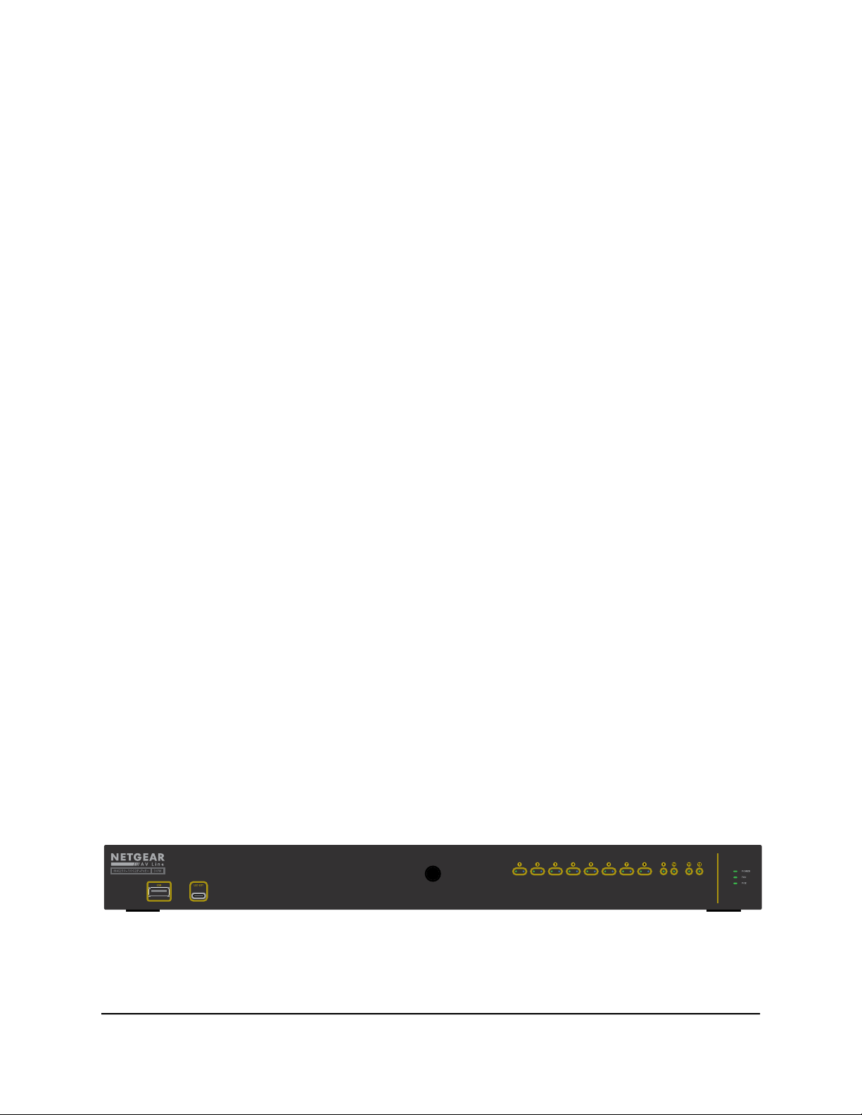
Front panel of the 8-port PoE+ and PoE++ models
The following figures illustrate the front panels of the 8-port PoE+ and PoE++ models,
the M4250-10G2F-PoE+, M4250-10G2XF-PoE+, and M4250-10G2XF-PoE++.
Figure 1. Front panel model M4250-10G2F-PoE+
Hardware Installation Guide13Hardware Overview
AV Line of Fully Managed Switches M4250 Series
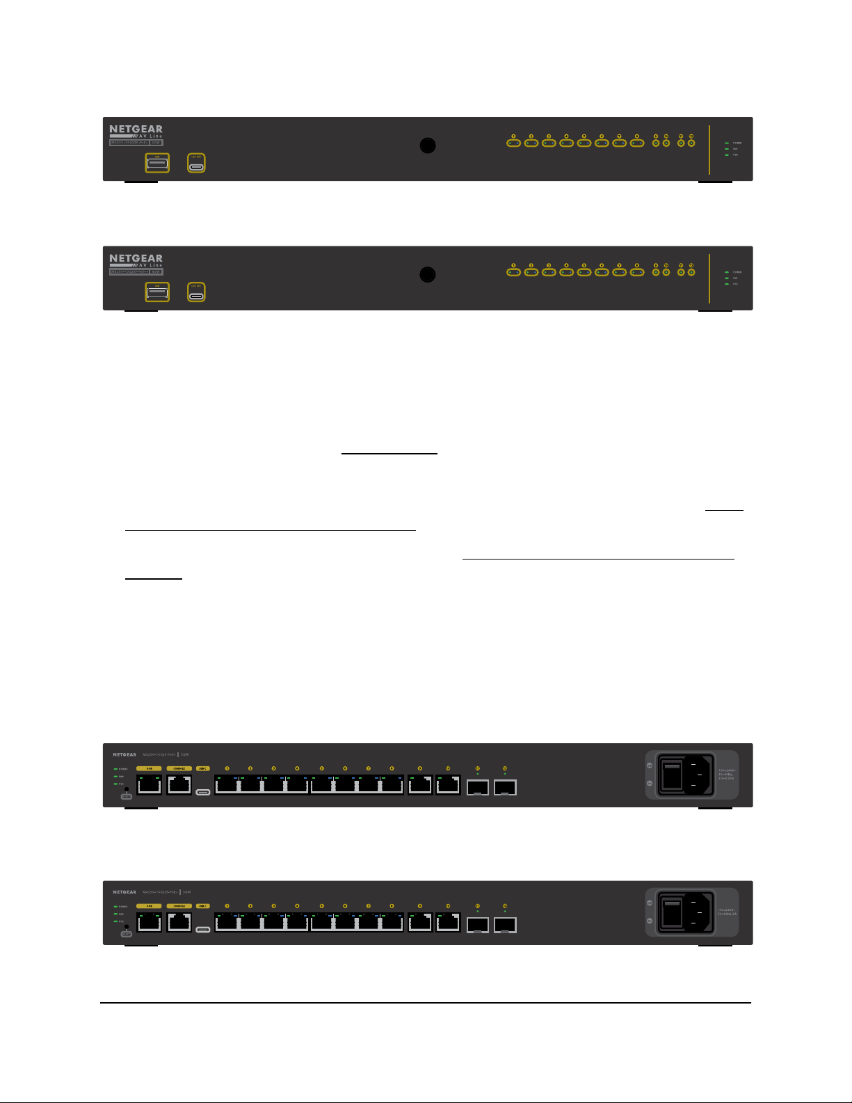
Figure 2. Front panel model M4250-10G2XF-PoE+
Figure 3. Front panel model M4250-10G2XF-PoE++
From left to right, the front panel of models M4250-10G2F-PoE+, M4250-10G2XF-PoE+,
and M4250-10G2XF-PoE++ provides the following common components, which are
clearly named or numbered on the front panel:
USB: One USB 2.0 port (see USB 2.0 port on page 37).
•
LED EXT: One LED extension port. This feature is currently not in use.
•
LEDs 1 through 12: Ports LEDs that are replicated from the back panel (see LEDs
•
of the 8-port PoE+ and PoE++ models on page 16).
POWER, FAN, and POE: System LEDs. (see LEDs of the 8-port PoE+ and PoE++
•
models on page 16).
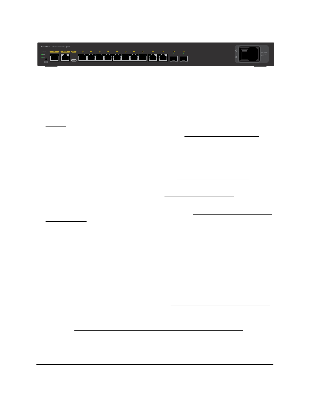
Back panel of the 8-port PoE+ and PoE++ models
The 8-port PoE+ and PoE++ models provide eight PoE+ or PoE++ 1GBASE-T ports,
two non-PoE 1GBASE-T ports, and two 1G or 10G SFP+ fiber uplink ports.
The following figures illustrate the back panels.
Figure 4. Back panel model M4250-10G2F-PoE+
Figure 5. Back panel model M4250-10G2XF-PoE+
Hardware Installation Guide14Hardware Overview
AV Line of Fully Managed Switches M4250 Series
Figure 6. Back panel model M4250-10G2XF-PoE++
From left to right, the back panel of models M4250-10G2F-PoE+, M4250-10G2XF-PoE+,
and M4250-10G2XF-PoE++ provides the following common components, which are
clearly named or numbered on the back panel:
POWER, FAN, and POE: System LEDs (see LEDs of the 8-port PoE+ and PoE++
•
models on page 16).
RESET: Recessed dual-function Reset button (see Dual-function Reset button on
•
page 36).
OOB: One out-of-band (OOB) Ethernet port (see Out-of-band 1G Ethernet port on
•
page 37) with a left LED that indicates the speed and a right LED that indicates the
activity (see LEDs of the 8-port PoE+ and PoE++ models on page 16).
CONSOLE: One RJ-45 RS-232 console port (see RJ-45 RS-232 console port on page
•
37).
USB C: One USB Type-C console port (see USB Type-C console port on page 38).
•
Ports 1 through 8: Eight PoE+ or PoE++ 10/100/1000 Mbps autosensing 1GBASE-T
•
RJ-45 ports, each with a left LED and a right LED (see LEDs of the 8-port PoE+ and
PoE++ models on page 16).
The type of PoE power and PoE budget depend on the model:
- Model M4250-10G2F-PoE+: Eight PoE+ (802.3at) ports with a total PoE budget
of 125W for the switch.
- Model M4250-10G2XF-PoE+: Eight PoE+ (802.3at) ports with a total PoE budget
of 240W for the switch.
- Model M4250-10G2XF-PoE++: Eight PoE++ (802.3bt) ports with a total PoE
budget of 720W for the switch.
Ports 9 and 10: Two 10/100/1000 Mbps autosensing 1GBASE-T RJ-45 ports s, each
•
with a combined speed and activity LED (see LEDs of the 8-port PoE+ and PoE++
models on page 16).
Ports 11 and 12: Two dedicated 1GBASE-X SFP or 10GBASE-X SFP+ fiber uplink
•
ports (see Transceiver modules and cables for SFP and SFP+ fiber ports on page
35), each with a combined speed and activity LED (see LEDs of the 8-port PoE+ and
PoE++ models on page 16).
Hardware Installation Guide15Hardware Overview

AV Line of Fully Managed Switches M4250 Series
The type of fiber ports depends on the model:
- Model M4250-10G2F-PoE+: Two 1GBASE-X SFP ports.
- Model M4250-10G2XF-PoE+: Two 10GBASE-X SFP+ ports.
- Model M4250-10G2XF-PoE++: Two 10GBASE-X SFP+ ports.
AC power receptacle and On/Off power switch: The AC receptacle accepts input
•
power of 100–240V ~ 50–60 Hz. The amperage depends on the model:
- Model M4250-10G2F-PoE+: 3.5–2.25A.
- Model M4250-10G2XF-PoE+: 5A.
- Model M4250-10G2XF-PoE++: 10A.
LEDs of the 8-port PoE+ and PoE++ models
This section describes the LED designations of the 8-port PoE+ and PoE++ models.
The system LEDs and ports LEDs on the back panel are replicated on the front panel.
(The exception are the port LEDs for the OOB port, which are not replicated on the front
panel.)
The LEDs are clearly named or numbered on the front panel and the back panel.
Table 1. LEDs of the 8-port PoE+ and PoE++ models
DescriptionLED
System LEDs
Power LED
Fan LED
POE LED
Solid green: The switch is powered on and operating normally.
Solid yellow: The switch is starting.
Off: Power is not supplied to the switch.
Solid green: The fans are functioning normally.
Solid yellow: One or more fans are malfunctioning.
Off: Sufficient (more than 7W of) PoE power is available.
Solid yellow: Less than 7W of PoE power is available.
Blinking yellow: At least once during the previous two minutes, less than 7W
of PoE power was available.
Hardware Installation Guide16Hardware Overview

AV Line of Fully Managed Switches M4250 Series
Table 1. LEDs of the 8-port PoE+ and PoE++ models (Continued)
DescriptionLED
Port LEDs
LEDs 1 through 8
1GBASE-T RJ-45 port LEDs
(two LEDs per ports)
LEDs 9 and 10
1GBASE-T RJ-45 port LED
(one LED per port)
LEDs 11 and 12 for model
M4250-10G2F-PoE+
1GBASE-X SFP+ port LED
(one LED per port)
Left LED, speed, activity, and link status:
Off: No link is established on the port.
Solid green: The port established a 1 Gbps link.
Blinking green: The port is transmitting or receiving packets at 1 Gbps.
Solid yellow: The port established a 10 or 100 Mbps link.
Blinking yellow: The port is transmitting or receiving packets at 10 or 100 Mbps.
Right LED, PoE status:
Off: No PoE-powered device (PD) is connected to the port.
Solid blue: A PD is connected and the port is supplying power successfully.
Solid yellow: Indicates one of the following failures, which prevents the port
from supplying power:
A short circuit occurred on the PoE power circuit.
•
The PoE power demand exceeds the available power.
•
The PoE current exceeds the PD’s classification.
•
An out-of-proper-voltage band condition occurred.
•
Off: No link is established on the port.
Solid green: The port established a 1 Gbps link.
Blinking green: The port is transmitting or receiving packets at 1 Gbps.
Solid yellow: The port established a 10 or 100 Mbps link.
Blinking yellow: The port is transmitting or receiving packets at 10 or 100 Mbps.
Off: No SFP module link is established on the fiber port.
Solid green: The fiber port established a 1 Gbps link.
Blinking green: The fiber port is transmitting or receiving packets at 1 Gbps.
Solid yellow: The fiber port established a 100 Mbps link.
Blinking yellow: The fiber port is transmitting or receiving packets at 100 Mbps.
LEDs 11 and 12 for models
M4250-10G2XF-PoE+ and
M4250-10G2XF-PoE++
10GBASE-X SFP+ port LED
(one LED per port)
OOB Ethernet port LEDs
(two LEDs per port, on the back
panel only)
Off: No SFP+ module link is established on the fiber port.
Solid green: The fiber port established a 10 Gbps link.
Blinking green: The fiber port is transmitting or receiving packets at 10 Gbps.
Solid yellow: The fiber port established a 1 Gbps link.
Blinking yellow: The fiber port is transmitting or receiving packets at 1 Gbps.
Left LED, speed status:
Solid green: The port established a 1 Gbps link.
Solid yellow: The port established a 10 or 100 Mbps link.
Off: No link is established on the port.
Right LED, activity and link status:
Solid green: The port established a link.
Blinking green: The port is transmitting or receiving packets.
Off: No link is established on the port.
Hardware Installation Guide17Hardware Overview
AV Line of Fully Managed Switches M4250 Series
Hardware descriptions of the 24-port PoE+ and PoE++ models
This section describes the switch hardware features for the following 8-port PoE+ and
PoE++ models:
Model M4250-26G4F-PoE+ (SKU GSM4230P)
•
-
24 PoE+ (802.3at) 1GBASE-T RJ-45 ports with a total PoE budget of 300W to be
shared among all ports
- Two 1GBASE-T RJ-45 ports
-
Four 1G SFP fiber uplink ports
Model M4250-26G4XF-PoE+ (SKU GSM4230PX)
•
-
24 PoE+ (802.3at) 1GBASE-T RJ-45 ports with a total PoE budget of 480W to be
shared among all ports
- Two 1GBASE-T RJ-45 ports
-
Four 10G SFP+ fiber uplink ports
Model M4250-26G4F-PoE++ (SKU GSM4230UP)
•
-
24 PoE++ (802.3bt) 1GBASE-T RJ-45 ports with a total PoE budget of 1440W
(with both internal power supply units connected) to be shared among all ports
- Two 1GBASE-T RJ-45 ports
-
Four 10G SFP+ fiber uplink ports
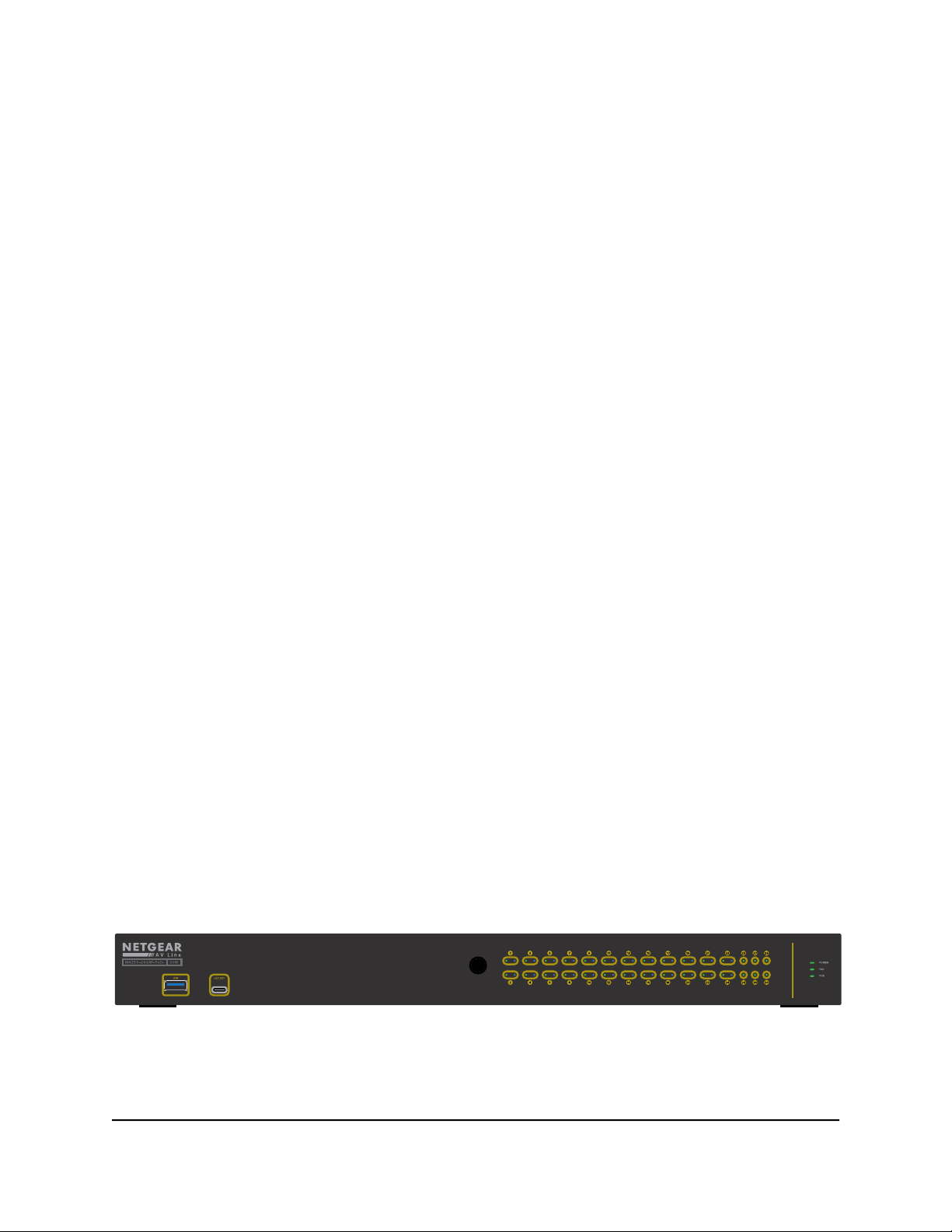
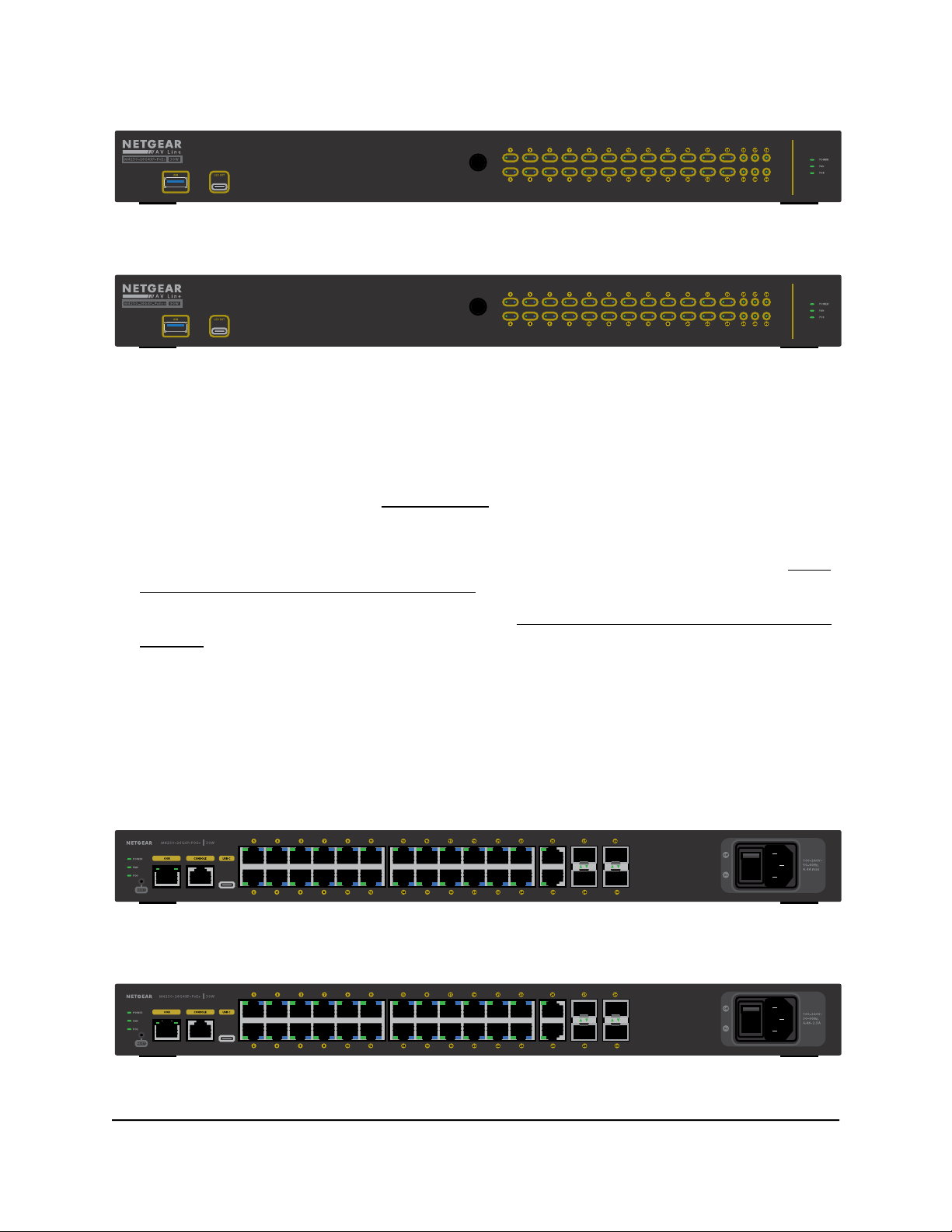
Front panel of the 24-port PoE+ and PoE++ models
The following figures illustrate the front panels of the 24-port PoE+ and PoE++ models,
the M4250-26G4F-PoE+, M4250-26G4XF-PoE+, and M4250-26G4F-PoE++.
Figure 7. Front panel model M4250-26G4F-PoE+
Hardware Installation Guide18Hardware Overview
AV Line of Fully Managed Switches M4250 Series
Figure 8. Front panel model M4250-26G4XF-PoE+
Figure 9. Front panel model M4250-26G4F-PoE++
From left to right, the front panel of models M4250-26G4F-PoE+, M4250-26G4XF-PoE+,
and M4250-26G4F-PoE++ provides the following common components, which are
clearly named or numbered on the front panel:
USB: One USB 2.0 port (see USB 2.0 port on page 37).
•
LED EXT: One LED extension port. This feature is currently not in use.
•
LEDs 1 through 30: Ports LEDs that are replicated from the back panel (see LEDs
•
of the 24-port PoE+ and PoE++ models on page 21).
POWER, FAN, and POE: System LEDs. (see LEDs of the 24-port PoE+ and PoE++
•
models on page 21).
Back panel of the 24-port PoE+ and PoE++ models
The 24-port PoE+ and PoE++ models provide 24 PoE+ or PoE++ 1GBASE-T ports, two
non-PoE 1GBASE-T ports, and four 1G or 10G SFP+ fiber uplink ports.
The following figures illustrate the back panels.
Figure 10. Back panel model M4250-26G4F-PoE+
Figure 11. Back panel model M4250-26G4XF-PoE+
Hardware Installation Guide19Hardware Overview
 Loading...