

NETGEAR M4100 Installation Manual
Hardware Installation Guide
NETGEAR Intelligent Edge Managed
Switches
M4100 Series
|
NETGEAR, Inc. |
Febuary 2020 |
350 East Plumeria Drive |
202-12076-01 |
San Jose, CA 95134, USA |

NETGEAR Managed Switch
Support and Community
Visit netgear.com/support to get your questions answered and access the latest downloads. You can also check out our NETGEAR Community for helpful advice at community.netgear.com.
Regulatory and Legal
Si ce produit est vendu au Canada, vous pouvez accéder à ce document en français canadien à https://www.netgear.com/support/download/.
(If this product is sold in Canada, you can access this document in Canadian French at https://www.netgear.com/support/download/.)
For regulatory compliance information including the EU Declaration of Conformity, visit https://www.netgear.com/about/regulatory/.
See the regulatory compliance document before connecting the power supply. For NETGEAR’s Privacy Policy, visit https://www.netgear.com/about/privacy-policy.
By using this device, you are agreeing to NETGEAR’s Terms and Conditions at https://www.netgear.com/about/terms-and-conditions. If you do not agree, return the device to your place of purchase within your return period.
Do not use this device outdoors. The PoE source is intended for intra building connection only.
Revision History
Publication Part Number |
Publish Date |
Comments |
|
|
|
|
|
202-12076-01 |
February 2020 |
• |
Per |
|
|
|
https://www.netgear.com/buisness/products/switches/man |
|
|
|
aged/m4100.aspx Title name updated from “NETGEAR |
|
|
|
ProSAFE Managed Switches” to “NETGEAR Intelligent |
|
|
|
Edge Managed Switches”. |
|
|
• Removed the Default Configuration Settings section. Said |
|
|
|
|
section is not applicable to the hardware installation guide. |
|
|
• The CD is no longer shipped with product. Removed info |
|
|
|
|
about CD. |
|
|
• Safety information updated on page 11 |
|
|
|
• |
Updated branding. |
|
|
• Updated support and compliance section. |
|
|
|
|
|
202-11217-04 |
August 2016 |
Updated model numbers on page 13; minor editorial revisions. |
|
|
|
|
|
202-11217-03 |
July 2016 |
Updated models in rack and wall installation instructions. |
|
|
|
|
|
202-11217-02 |
November 2013 |
v1.0 |
|
|
|
|
|
202-11217-01 |
January 2013 |
v1.0 |
|
|
|
|
|
2 |
Hardware Installation Guide |

Contents
Chapter 1 Introduction
Front panels and LEDs . . . . . . . . . . . . . . . . . . . . . . . . . . . . . . . . . . . . . . . . . . . . . 4 Rear panels . . . . . . . . . . . . . . . . . . . . . . . . . . . . . . . . . . . . . . . . . . . . . . . . . . . . . . 9 instructions. . . . . . . . . . . . . . . . . . . . . . . . . . . . . . . . . . . . . . . . . . . . . . . . . . . . . . 11
Chapter 2 Hardware Installation
Package contents . . . . . . . . . . . . . . . . . . . . . . . . . . . . . . . . . . . . . . . . . . . . . . . . 13 Protecting against electrostatic discharge . . . . . . . . . . . . . . . . . . . . . . . . . . . 13 Unpack the hardware . . . . . . . . . . . . . . . . . . . . . . . . . . . . . . . . . . . . . . . . . . . . . 14 Installation . . . . . . . . . . . . . . . . . . . . . . . . . . . . . . . . . . . . . . . . . . . . . . . . . . . . . . 14
Select a location. . . . . . . . . . . . . . . . . . . . . . . . . . . . . . . . . . . . . . . . . . . . . . .15 Install the switch. . . . . . . . . . . . . . . . . . . . . . . . . . . . . . . . . . . . . . . . . . . . . . .16 Install the M4100-D12G or M4100-D10-PoE using magnets. . . . . . . . .19 Check the installation . . . . . . . . . . . . . . . . . . . . . . . . . . . . . . . . . . . . . . . . . .20 Connect to power and check the LEDs . . . . . . . . . . . . . . . . . . . . . . . . . . .20
SFP modules . . . . . . . . . . . . . . . . . . . . . . . . . . . . . . . . . . . . . . . . . . . . . . . . . . . . 21 Connect equipment to the switch . . . . . . . . . . . . . . . . . . . . . . . . . . . . . . . . . . 22
RJ-45 Ports . . . . . . . . . . . . . . . . . . . . . . . . . . . . . . . . . . . . . . . . . . . . . . . . . . .22
Connect a console to the switch . . . . . . . . . . . . . . . . . . . . . . . . . . . . . . . . . . . 22
Chapter 3 Troubleshooting
Troubleshooting chart . . . . . . . . . . . . . . . . . . . . . . . . . . . . . . . . . . . . . . . . . . . . 24 Additional troubleshooting suggestions . . . . . . . . . . . . . . . . . . . . . . . . . . . . 25
Appendix A Technical Specifications
3

1
1Introduction
The NETGEAR M4100 Series Intelligent Edge Managed Switches provide state-of-the-art, high-performance, IEEE-compliant network solutions. They include powerful management features that you can use to eliminate bottlenecks, boost performance, and increase productivity. The M4100 Series switches include the following:
•M4100-26G
•M4100-50G
•M4100-26-POE
•M4100-26G-POE
•M4100-50G-POE+
•M4100-50-POE
•M4100-D10-POE
•M4100-D12G
•M4100-12GF
•M4100-D12G-POE+
•M4100-24G-POE+
•M4100-12G-POE+
This guide describes hardware installation and basic troubleshooting for these managed switches.
These switches can be freestanding, wall mounted, or rack mounted in a wiring closet or an equipment room. For information about features for each product, visit the NETGEAR website at https://www.netgear.com.
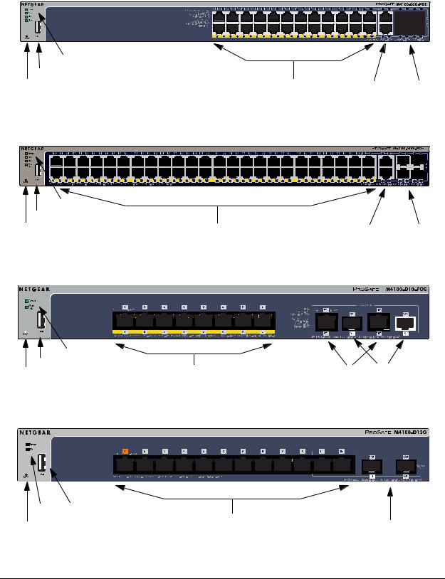
Front panels and LEDs
The following figures show the front panels of the 4100 series Intelligent Edge Managed switches. The front panel contains LEDs, a Reset button, a USB flash port, RJ45 ports, copper (RJ-45)/fiber (SFP) combo ports, and USB console selection slide switch, and USB console port.
4

NETGEAR Managed Switch
|
LEDs |
|
USB port |
RJ-45 ports |
SFP ports |
Reset button |
Figure 1. M4100-26G front panel

 Power
Power

 Fan
Fan

 RPS
RPS
Reset |
USB |
RJ45 SPD/Link/ACT mode: Green = 1G Yellow = 10/100M Blink = ACT |
|
| <![if ! IE]> <![endif]>Combo Ports |
SFP SPD/Link/ACT mode: Green = Link at 1G Yellow = Link at 100M Blink = ACT
LEDs |
|
|
USB port |
|
SFP ports |
Reset button |
RJ-45 ports |
Figure 2. M4100-50G front panel
LEDs |
|
|
USB port |
POE ports |
RJ-45 ports SFP ports |
Reset button |
Figure 3. M4100-26-POE front panel
LEDs |
|
|
USB port |
POE ports |
RJ-45 ports SFP ports |
Reset button |
Figure 4. M4100-50-POE front panel
Introduction |
5 |
Hardware Installation Guide |
NETGEAR Managed Switch
LEDs |
|
|
USB port |
POE ports |
|
Reset button |
RJ-45 ports SFP ports |
Figure 5. M4100-26G-POE front panel
LEDs |
|
|
USB port |
POE ports |
RJ45 ports SFP ports |
Reset button |
Figure 6. M4100-50G-POE+ front panel
LEDs |
|
|
USB port |
POE ports |
RJ45 ports SFP ports |
Reset button |
Figure 7. M4100-D10-POE Front Panel
LEDs USB port
Reset button |
RJ45 ports |
SFP ports |
Figure 8. M4100-D12G front panel
Introduction |
6 |
Hardware Installation Guide |
NETGEAR Managed Switch
PoE SPD/Link/ACT
|
|
|
PoE (Max 30W per port): |
|
|
|
|
|
|
|
|
|
|
|
|
|
|
|
|
|
|
|
|
|
|
|
|
|
|
|
|
|
|
|
|
|
|
|
|
|
Power |
|
|
Off = No PD |
|
|
|
|
|
|
|
|
|
|
|
|
|
|
|
|
|
|
|
|
|
|
|
|
|
|
|
|
|
|
|
|
|
|
|
|
|
|
|
Green = PoE Powered |
|
|
|
|
|
|
|
|
|
|
|
|
|
|
|
|
|
|
|
|
|
|
|
|
|
|
|
|
|
|
|
|
|
|
|
|
|
|
Fan |
|
|
Yellow = PoE Fault |
|
|
|
|
|
|
|
|
|
|
|
|
|
|
|
|
|
|
|
|
|
|
|
|
|
|
|
|
|
|
|
|
|
|
|
|
|
PD |
|
|
RJ45 SPD/Link/ACT mode: |
|
|
|
|
|
|
|
|
|
|
|
|
|
|
|
|
|
|
|
|
|
|
|
|
|
|
|
|
|
|
|
|
|
|
|
|
|
|
|
|
Green = 1G |
|
|
|
|
|
|
|
|
|
|
|
|
|
|
|
|
|
|
|
|
|
|
|
|
|
|
|
|
|
|
|
|
|
|
|
|
|
MaxPoE |
|
|
Yellow = 10/100M |
|
|
|
|
|
|
|
|
|
|
|
|
|
|
|
|
|
|
|
|
|
|
|
|
|
|
|
|
|
|
|
|
|
|
|
|
|
|
|
|
Blink = ACT |
|
|
|
|
|
|
|
|
|
|
|
|
|
|
|
|
|
|
|
|
|
|
|
|
|
|
|
|
|
|
|
|
|
|
|
|
|
Reset |
|
|
|
|
|
|
|
|
|
|
|
|
|
|
|
|
|
|
|
|
|
|
|
|
|
|
|
|
|
|
|
|
|
|
|
|
|
|
|
|
|
|
|
|
|
|
|
|
|
|
|
|
|
|
|
|
|
|
|
|
|
|
|
|
|
|
|
|
|
|
|
|
|
|
|
|
|
|
|
|
|
USB |
|
|
|
|
|
|
|
|
|
|
|
|
|
|
|
|
|
|
|
|
|
|
|
|
|
|
|
|
|
|
|
|
|
|
|
|
|
|||


 M4100-24G-POE+
SFP SPD/Link/ACT mode
Green = Link at 1G
Yellow = Link at 100M
Blink = ACT
USB 
 DB9
DB9
|
Console(USB) |
SPD/Link/ACT |
115200,N,8,1 |
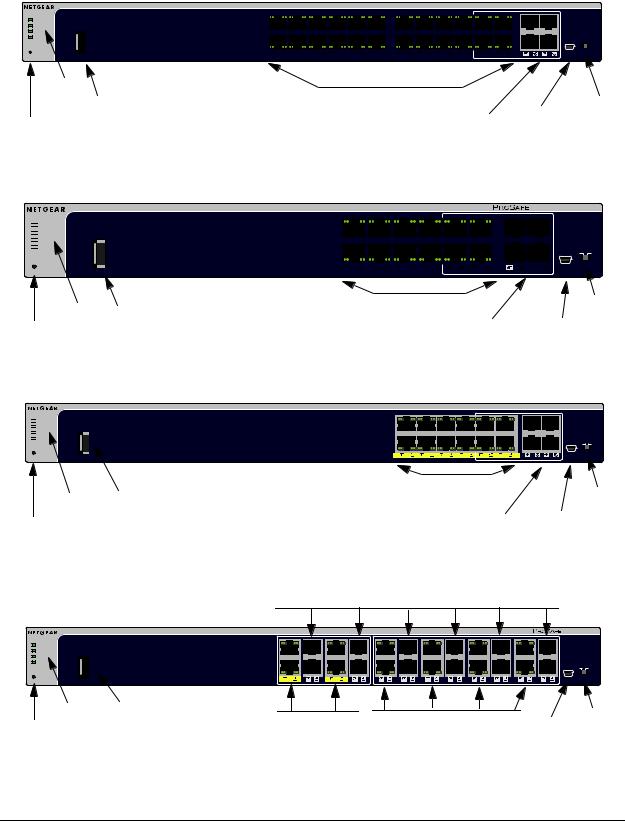
LEDs
USB port
Reset button
Figure 9. M4100-24G-POE+ front panel

 Power
Power

 Fan
Fan

 PD
PD

 MaxPoE
Reset |
USB |
LEDs USB port
Reset button
Figure 10. M4100-D12G-POE+ front panel

 Power
Power

 Fan
Fan

 PD
PD

 MaxPoE
Reset |
USB |
LEDs USB port
Reset button
Figure 11. M4100-12G-POE+ front panel
|
|
Mini |
Console |
|
|
switch |
|
POE ports |
SFP ports USB port |
||
|
|
|
|
|
|
|
|
|
|
|
|
|
|
|
|
|
|
|
|
|
|
|
|
M4100-D12G-POE+ |
||||
|
PoE SPD/Link/ACT |
|
|
|
|
|
|
|||||||||||||||||||||
PoE (Max 30W per port): |
|
|
|
|
|
|
|
|
|
|
|
|
|
|
|
|
|
|
|
|
|
|
|
|
|
|
|
SFP SPD/Link/ACT mode |
Off = No PD |
|
|
|
|
|
|
|
|
|
|
|
|
|
|
|
|
|
|
|
|
|
|
|
|
|
|
|
Green = Link at 1G |
Green = PoE Powered |
|
|
|
|
|
|
|
|
|
|
|
|
|
|
|
|
|
|
|
|
|
|
|
|
|
|
|
Yellow = Link at 100M |
Yellow = PoE Fault |
|
|
|
|
|
|
|
|
|
|
|
|
|
|
|
|
|
|
|
|
|
|
|
|
|
|
|
Blink = ACT |
PoE-PD (Port 1, 2): |
|
|
|
|
|
|
|
|
|
|
|
|
|
|
|
|
|
|
|
|
|
|
|
|
|
|
|
|
Off = No PSE |
|
|
|
|
|
|
|
|
|
|
|
|
|
|
|
|
|
|
|
|
|
|
|
|
|
|
|
|
Green = PSE 30w |
|
|
|
|
|
|
|
|
|
|
|
|
|
|
|
|
|
|
|
|
|
|
|
|
|
|
|
|
Yellow = PSE 15.4w |
|
|
|
|
|
|
|
|
|
|
|
|
|
|
|
|
|
|
|
|
|
|
|
|
|
|
|
USB DB9 |
RJ45 SPD/Link/ACT mode: |
|
|
|
|
|
|
|
|
|
|
|
|
|
|
|
|
|
|
|
|
|
|
|
|
|
|
|
|
Green = 1G |
|
|
|
|
|
|
|
|
|
|
|
|
|
|
|
|
|
|
|
|
|
|
|
|
|
|
|
|
Yellow = 10/100M |
|
|
|
|
|
|
|
|
|
|
|
|
|
|
|
|
|
|
|
|
|
|
|
|
|
|
|
|
Blink = ACT |
|
|
|
|
|
|
|
|
|
|
|
|
|
|
|
|
|
|
|
|
|
|
|
|
|
|
|
Console(USB) |
|
|
|
|
|
|
|
|
|
|
|
|
|
|
|
|
|
|
|
|
SPD/Link/ACT |
|
|
|
|
|
115200,N,8,1 |
||
|
|
|
|
|
|
|
|
|
|
|
|
|
|
|
|
|
|
|
|
|
|
|
|
Mini |
Console |
|||
|
|
|
|
|
|
|
|
|
|
|
|
|
|
|
|
|
|
|
|
|
|
|
|
|||||
|
|
|
|
|
|
|
POE |
ports |
|
switch |
||||||||||||||||||
|
|
|
|
|
|
|
|
|
|
|
|
|
|
|
SFP ports |
|
USB prt |
|||||||||||


 M4100-12G-POE+
PoE SPD/Link/ACT
PoE (Max 30W per port): |
SFP SPD/Link/ACT mode |
|
Off = No PD |
Green = Link at 1G |
|
Green = PoE Powered |
Yellow = Link at 100M |
|
Yellow = PoE Fault |
|
|
|
Blink = ACT |
|
RJ45 SPD/Link/ACT mode: |
|
|
Green = 1G |
|
|
Yellow = 10/100M |
|
|
Blink = ACT |
USB |
DB9 |
|
||
|
Console(USB) |
|
SPD/Link/ACT |
115200,N,8,1 |
|
|
|
|
Console |
|
POE ports |
|
|||
Mini |
switch |
|||
|
|
|||
|
SFP ports USB prt |
|||
SFP ports
|
PoE (Max 30W per port): |
Power |
OFF = No PD |
Green = PoE Powered |
|
Fan |
Yellow = PoE Fault |
||
|
PD |
|
Link/ACT mode: |
|
|
|
|
Green = Link at 1G |
|
|
MaxPoE |
|
Yellow = Link at 10/100M |
|
|
|
|
Blink = ACT |
|
|
|
|
SPF Link/Act mode: |
|
|
|
|
Green = Link at 1G |
|
Reset |
|
|
Yellow = Link at 100M |
|
USB |
||||
Blink = ACT |
||||
|
|
|
|
M4100-12GF |
|
PoE |
SPD/Link/ACT |
SPD |
Link/ACT |
SFP |
|
|
|
|
|
Green = 1G |
|
|
|
|
|
Yellow = 10/100M |
|
|
|
|
|
Link/Act mode |
|
|
|
|
|
OFF = No Link |
|
|
|
|
|
Green = Link |
|
|
|
|
|
Blinking = ACT |
|
|
|
|
|
USB |
DB9 |
|
|
|
|
Console(USB) |
|
|
SPD/Link/ACT |
|
SPD/Link/ACT |
115200,N,8,1 |
|
LEDs USB Port |
POE ports |
RJ45 ports |
Mini |
Console |
Reset button |
USB prt |
switch |
Figure 12. M4100-12GF front panel
Introduction |
7 |
Hardware Installation Guide |

NETGEAR Managed Switch
Table 1. LED descriptions
|
LED |
Description |
|
|
|
|
|
|
Power |
Solid green: Internal power supply operating normally and supplying power to the |
|
|
|
switch. |
|
|
|
Solid yellow: The system is in boot-up stage. |
|
|
|
Blinking yellow: Power module is present but has failed. |
|
|
|
Off: Power is disconnected. |
|
|
|
|
|
|
Fan |
Solid green: The fan is operating normally. |
|
|
|
Solid yellow: The fan has failed. |
|
|
|
Off: No fan is detected. |
|
|
|
|
|
|
RPS |
Solid green: RPS connected (using internal power supply’s power). |
|
|
|
Solid yellow: The internal power supply has failed and the RPS is providing power to |
|
|
|
the switch. |
|
|
|
Blinking yellow: RPS is present but RPS has failed. |
|
|
|
Off: RPS disconnected. |
|
|
|
Note: Only for M4100-26G, 50G, 26-POE, 26G-POE, 50G-POE+, and 50-POE |
|
|
PD |
Solid green: PD port 1 is connected to PSE getting 802.3at specified power. |
|
|
|
Blinking green: PD port 1 is connected to PSE getting 802.3af specified power. |
|
|
|
Off: PD port 1 is not connected to PSE. |
|
|
|
Note: Only for M4100-D12G, -24G-POE, D12G-POE, 12G-POE+, -12GF |
|
|
Max PoE |
Solid yellow: Indicates less than 7 watts of PoE power is available. |
|
|
|
Blinking yellow: Indicates the PoE MAX LED was active in the previous 2 minutes. |
|
|
|
Off: There is at least 7 watts of PoE power available for another device. |
|
|
|
|
|
|
SPD/Link/ACT |
Off: No link is established on the port. |
|
|
(RJ-45 port) |
Solid green: A valid 1000 Mbps link is established on the port. |
|
|
|
Blinking green: Packet transmission or reception is occurring on the port at 1000 |
|
|
|
Mbps. |
|
|
|
Solid yellow: A valid 10/100 Mbps link is established on the port. |
|
|
|
Blinking yellow: Packet transmission or reception is occurring on the port at 10/100 |
|
|
|
Mbps. |
|
|
|
Note: If combo port media change to fiber, the Ethernet LED changes to off status. |
|
|
|
|
|
|
PoE |
Off: No PoE powered device (PD) connected. |
|
|
|
Solid green: The PoE powered device (PD) is connected and the port is supplying |
|
|
|
power successfully. |
|
|
|
Solid yellow: Indicates that one of the following failures resulted in stopping power to |
|
|
|
that port: |
|
|
|
- Short circuit on PoE power circuit |
|
|
|
- PoE power demand exceeds power available |
|
|
|
- PoE current exceeds PD’s classification |
|
|
|
- Out of proper voltage (44 VDC–57 VDC for af, 50 VDC–57 VDC for at) |
|
|
|
|
|
|
|
|
|
Introduction |
8 |
Hardware Installation Guide |

NETGEAR Managed Switch
Table 1. LED descriptions (continued)
LED |
Description |
|
|
Link/ACT |
Off: No link is established on the port. |
(RJ45 port) |
Solid green: A valid link is established on the port. |
|
Blinking green: Packets transmission or reception is occurring on the port. |
|
Note: If a combo port media changes to fiber, the copper port LED |
|
changes to off status. |
SPD (RJ45 port) |
Off: No link is established on the port. |
|
Solid green: A valid 1000 Mbps link is established on the port. |
|
Solid yellow: A valid 10/100 Mbps link is established on the port. |
|
|
PoE-PD |
Off: No PSE is connected or PSE is connected but connection has failed. |
|
Solid green: The PSE is connected and get 30 W power from PSE successfully. |
|
Solid yellow: The PSE is connected and get 15.4 W power from PSE successfully. |
|
|
SPD/Link/ACT |
Off: No SFP/SFP+ module link is established on the port. |
(SFP port) |
Solid green: A valid 1000 Mbps SFP+ module link is established on the port. |
|
Blinking green: The port is transmitting or receiving packets at 1000 Mbps. |
|
Solid yellow: A valid 100 Mbps SFP module link is established on the port. |
|
Blinking yellow: Packet transmission or reception is occurring on the port at |
|
100 Mbps. |
|
Note: If combo port media changes to copper, the SFP port LED changes to off |
|
status. |
|
|
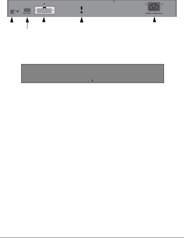
Rear panels
The rear panels have a DB9 console port, a mini USB port (only for M4100-26G, 50G, 26-POE, 26G-POE, 50G-POE+, 50-POE, D12-PoE, and D12G), a redundant power supply connector (only for M4100-26G, 50G, 26-POE, 26G-POE, 50G-POE+, 50-POE, 12GF, 24G-POE+, and 12G-POE+), and a standard AC power receptacle for the supplied power cord.
Introduction |
9 |
Hardware Installation Guide |
NETGEAR Managed Switch
|
|
|
|
|
|
|
|
|
|
|
|
|
|
|
|
|
|
|
|
|
|
|
|
|
|
|
Mini |
Console |
RPS |
Lock |
AC power |
||||
USB |
port |
power supply |
|
|
connector |
|||
port |
|
connector |
|
|
|
|
||
Figure 13. M4100-26G, 50G, 26-POE, 26G-POE, 50G-POE+, and 50-POE rear panels
Console switch
|
|
|
|
|
|
|
|
|
|
|
|
|
Console |
Lock |
Power adapter |
||
|
ports |
|
|
connector |
|
|
|
|
|
||
Figure 14. M4100-D10-POE and M4100-D12G rear panels
|
|
|
|
|
|
|
|
|
|
|
|
|
|
Console |
RPS |
Lock |
AC power |
|||
port |
power supply |
|
|
connector |
||
|
|
connector |
|
|
|
|
Figure 15. M4100-12GF, 24G-POE+, 12G-POE+ rear panel
Introduction |
10 |
Hardware Installation Guide |
 Loading...