

Page 1

Application Note
OpenSource User Guide for OpenSource Wireless-G
Router KWGR614
Summary
This document provides further pr od uc t i nf ormation for open source developers wh o a re
interested in using this platform to develop their customization applications.
WARNING: Opening the router housing or putting in any cus tomer software on the
router will void the warranty on your router
Specifications
This section describes the hardware memory specifications and the module and software
specifications for the OpenSour ce Wi re less-G Router KWGR614.
Hardware Memory Specificat ions
Total memory:
• Flash: 4MB
• SDRAM: 16MB
Memory usage of the latest router firmware:
• Flash: 2MB used = 1,804KB (router firmware V1.0.1-10.17WW) + 192KB
(Bootloader + BoardInfo + POT + Configuration)
• SDRAM: about 8.5MB (without including the dynamic memory allocation)
Module and Software Specifications
The following table lists the functional modules of the KWGR614 router and the source
and versions of the different m odu les. You can find more information on these functio n al
modules directly from the source of the packages.
Module Package Version Location (directory)
NAT/NAPT RomeDriver-Realtek 3.6.3 linux-2.4.x/drivers/net/re865x/rtl865x
RIPv1/RIPv2 Copyright 2005, DNI 1.0.0 user/ripd
DHCP
server/client
udhcpd/udhcpc of
Busybox V1.00-pre2
0.9.10 user/busybox/networking/udhcp
DNS Proxy Dnrd 2.17.2 user/dnrd-dnshijack
Page 2

Dynamic DNS ez-ipupdate 3.0.11b7 user/ez-ipupdate-3.0.11b7
Web Server BOA 0.94 user/boa
UPNP Copyright 2005, DNI 1.0.0 user/upnp
Telstra's Big
Pond
Email Smtpclient 1.0.0 user/smtpclient
Schedule Crond of Busybox V1.00-
PPP/PPPoE Pppd 2.3.8 user/pppd
PPTP Client pptp-client 1.3.1 user/pptp-client
Ntpclient Copyright 2005, DNI 1.0.0 user/ntpclient
Miscellaneous Copyright 2005, DNI 1.0 .0 user/dniutil, user/init
Wireless driver Copyright Realtek 1.12 linux-
L2TP l2tpd 0.69 user/l2tpd
Iptables iptables 1.2.7a user/iptables
Bpalogin V2.0 user/bpalogin
1.0.0 user/busybox/miscutils/crond.c
pre2
2.4.x/drivers/net/wireless/rtl8185
Making a Console Debug Interface for th e KWGR614 Router
This section provides instructions on how to make a console interface to a NETGEAR
KWGR614 wireless router for the developer’s firmware development and debugging.
The following example schematic illustrates using a MAX3232, the RS-232 Line
Driver/Receiver from Texas Instruments (TI), to make a console board.
You can download a datasheet for the MAX3232.from the Texas Instruments website at:
http://focus.ti.com/lit/ds/symlink/max3232.pdf
.
Page 3
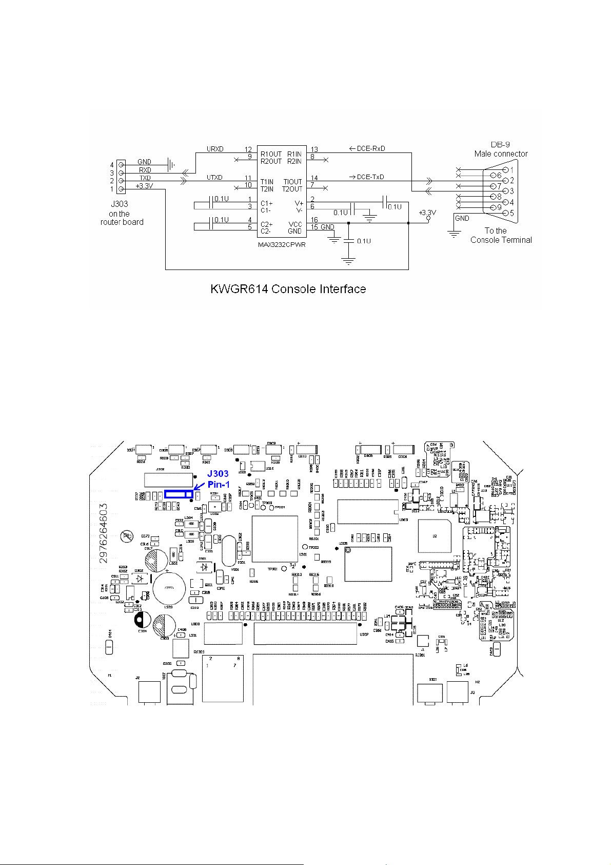
Note: The DB9 (male) connector is wired as a D CE (thi nk of this as a peripheral serial
port), and can be connected directly t o t he ser ia l p ort on a host PC. This gives you access
to the built-in serial console on the router (using the protocol of 38400bps, 8 data bits,
none parity, 1 stop bit, without flow control).
To make a console debug interface for t he KWG R614 router:
Connect the console board to the pin header (J303) on the router boar d.
The pin-out of J303 on the KWGR614 board is as follows:
Page 4

• Pin 1: VDDH (3.3V)
• Pin 2: TxD
• Pin 3: RxD
• Pin 4: GND (Ground)
There are third-party vendors who provide compatible console boards, such as the
AD233AK/AD233BK RS232 adapter kits at:
http://www.compsys1.com/workbench/On_top_of_the_Bench/Max233_Adapter/max233
adapter.html
Make sure the third-party adapter board is connected correctly to the corresponding pins
of J303 on the router board.
Page 5

Source Code and Executable
This section describes the steps and procedures that are required to download the source
code, install the toolchain, compile and link the existing source code, and develop the
user applications for the KWGR614 Router.
Note: The procedures in this guide were performed on Suse Linux 10.1.
1. Download KWGR614_V1.0.1_10.17WW_gpl_package.zip from the NETGEAR Open
Source web site at: http://kbserver.netgear.com/kb_web_files/open_src.asp
.
Note: V1.0.1_10.17 is the firmware versi on number. WW denotes Worldwide. You c an
download other versions of this document, for example, North America (NA).
2. Unzip KWGR614_V1.0.1_10.17WW_gpl_package.zip (or the version you
downloaded). The zip file contains the following files:
o KWGR614_README.txt (the OpenSource User Guide)
o KWGR614_V1.0.1_10.17WW_src.tar.bz2
o toolchain_mips_20050831.tar.bz2
3. Unpack the source code in tar –xvf KWGR614_V1.0.1_10.17WW_src.tar.bz2. This
creates a sub-directory KWGR614_xxx/. (xxx -> V1.0.1_10.17WW (xxx denotes the
version number.)
We recommend that you read the follo wing documents in this directory before you
proceed.
• /vendors/Documentation/KWGR614_README.txt
• /SOURCE
• /README
• /Documentation/Adding-User-Apps-HOWTO
• /Documentation/Addid-Platforms-HOWTO
4. Install the Tool chain in the r oo t directory by typing:
# cd/
mkdir uclibc
# cd uclibc
# tar jxvf toolchain_mips_20050831.tar.bz2
# mv toolchain_mips.pv.0831 toolchain_mips
Page 6

Note: Root user permissions may be required to create the uclibc directory and install the
tool chain into the root direc t ory of the file system.
5. Compile.
a. Change the working directory to KWGR614_xxx/.
b. Type make menuconfig, and customize your kernel config options, as follows:
Target Platform Selection --->
[ * ] Customize Kernel Settings (NEW)
Exit, Exit, Save configuration? yes
Exit, Save configuration? yes
Note: If you are building runtime image for the first time, be sure to save the
configuration
settings.
when leaving make menuconfig, even if no change is made to the default
c. Type make dep.
d. (Optional) If you need to customize busybox, go to
KWGR614_xxx/user/busybox/, and type
level application you need. Then go back to KWGR614_xxx/, and type
again. This updates all dependencies.
dep
make menuconfig to select the user
make
6. Type make. This builds the kernel, user apps, and cre ate image file run.bix under
KWGR614_xxx/images/ directory.
After compiling and linking the existing source code alrea dy provided, you can now
upload the KWGR614_xxx/images/run.bix file directly to the router after connecting the
router to your PC and using the Ro u te r f irmware Upgrade page on the Router W e b GUI.
Developing Custom Applications on the OpenSource Router
This section describes how to develop cus t om applications on this router.
Setting the Version String
Set your custom version string in th e file user/dni/nvram_realtek.c by defining
OS_VERSION. Be certain to rem ove any d uplicate definition.
user/dni/nvram_realtek.c
Page 7

#define OS_VERSION “V1.01.01 Custom”
Note: You can remove the country suffix from the version string by redefining
EXTENSION.
user/dni/nvram_realtek.c
New NVRAM Parameters
#if 1
#ifdef EXTENSION
#undef EXTENSION
#endif
#define EXTENSION “”
#endif
1. Define the structure of t h e pa rameter.
user/boa/src/rtl865x/board.h
#define MAX_QUESTION_LENGTH 64
typedef struct exampleParam_s
{
char question[MAX_QUESTION_LENGTH];
int answer;
} exampleParam_t;
2. Add the new parameter to the main parameter structure to include it in the
configuration set.
user/boa/src/rtl865x/board.h
typedef struct romeCfgParam_s
{
. . .
exampleParam_t exampleParam;
} romeCfgParam_t;
Page 8

3. Create get/set functions for the parameter.
user/dniutil/nvram_realtek.c
char *
nvram_get_example_question (char *name)
{
DPRINTF("nvram_get(\"%s\")\n", name);
sprintf(str, "%s", pRomeCfgParam->exampleParam.question);
return (str);
}
int
nvram_set_example_question(char *name, char *value)
{
DPRINTF("nvram_set(\"%s\", \"%s\")\n", name, value);
strncpy(pRomeCfgParam->exampleParam.question, value, \
sizeof(pRomeCfgParam->exampleParam.question));
return 1;
}
char *
nvram_get_example_answer (char *name)
{
DPRINTF("nvram_get(\"%s\")\n", name);
sprintf(str, "%d", pRomeCfgParam->exampleParam.answer);
return (str);
}
int
nvram_set_example_question(char *name, char *value)
{
DPRINTF("nvram_set(\"%s\", \"%s\")\n", name, value);
pRomeCfgParam->exampleParam.answer = atoi(value);
return 1;
}
4. Add the get/set handlers to the NVRAM ha n dler table.
user/dniutil/nvram_realtek.c
struct ej_nvram_handler nvram_handlers[] =
{
nvram_set_example_question},
nvram_set_example_answer},
};
. . .
{"example_question", nvram_get_example_question,
{"example_answer", nvram_get_example_answer,
{ NULL, NULL, NULL },
Page 9

5. Declare an instance of the parameter f or runtime memory use.
user/boa/src/dni/board.c
exampleParam_t ramExampleParam; //nvram example
6. Define default values for the parameter.
user/boa/src/dni/board.c
// nvram example
exampleParam_t exampleParamDefault[1] =
{
{
"What is the meaning of life, the universe, and
everything?",
42
}
};
7. Define the initialization function.
user/boa/src/dni/board.c
uint32 example_init(void)
{
/* read cfg from cfgmgr */
if (cfgmgr_read(CFGMGR_TABID_EXAMPLE, \
(void*)&(pRomeCfgParam->exampleParam), \
sizeof(struct exampleParam_t))!=0)
{
printf("example_init: call cfgmgr_read fail\n");
/* take proper actions */
return NOT_OK;
}
//printf("example_init\n");
return OK;
} /* end example_init */
Page 10

8. Add the function to system initialization.
user/boa/src/dni/board.c
uint32 sysInit(void)
{
. . .
/* init nvram example */
example_init();
. . .
} /* end sysInit */
9. Add an ID to the configuration management table a nd to the control table.
user/boa/src/rtl865x/rtl_board.h
enum _board_cfgmgr_tabId_e {
. . .
CFGMGR_TABID_EXAMPLE,
CFGMGR_TABID_MAX
};
user/boa/src/dni/board.c
static _board_cfgmgr_ctrl_t _board_cfgmgr_ctrlTbl[CFG MGR_TABID_MAX+1]
=
{
. . .
{CFGMGR_TABID_EXAMPLE, exampleParamDefault,
(sizeof(exampleParamDefault))},
{CFGMGR_TABID_MAX, NULL, 0}
};
10. Create a save function for the parameter.
user/boa/src/dni/board.c
Page 11

int example_cfg_save(void)
{
cfgmgr_write(CFGMGR_TABID_EXAMPLE, \
(void*)&(pRomeCfgParam->exampleParam),\
sizeof(exampleParam_t));
cfgmgr_task();
return 1;
}
11. Add the parameter to the NVRAM commit function.
user/boa/src/dni/board.c
int nvram_commit(void)
{
. . .
cfgmgr_write(CFGMGR_TABID_EXAMPLE, \
(void*)&(pRomeCfgParam->exampleParam), \
sizeof(exampleParam_t));
cfgmgr_task();
return 1;
}
12. Clean and rebuild userspace after any changes to board.h.
At the shell prompt, type:
work> cd user; make clean; cd ..; make
Web Page Integration
The boa web server is used. Custom web pages are integrated at:
user/boa/src/www_WW/
1. Create the main page in the above directory. Use <% nvram_get(“variable
”); %> to insert the value of an NVRAM variable.
name
Page 12

user/boa/src/www_WW/example.html
<html>
<head>
<meta http-equiv="content-type" content="text/html;charset=ISO-8859-
1">
<META http-equiv='Pragma' CONTENT='no-cache'>
<META HTTP-EQUIV="Cache-Control" CONTENT="no-cache">
<title>Router Customization Example</title>
<link rel="stylesheet" href="/form1.css" type="text/css">
<script language="javascript" type="text/javascript">
<!-- hide script from old browsers
function loadhelp(fname)
{
if(top.helpframe != null) {
top.helpframe.location.href="help/help"+fname+".html"
}
}
//-->
</script>
</head>
<body bgcolor="#ffffff" leftmargin="0" topmargin="0" margi nwidth="0"
marginheight="0" onload="loadhelp('_example');">
Q: <% nvram_get(“example_question”); %><br>
A: <% nvram_get(“example_answer”); %>
</body>
</html>
2. Create the help file in the help directory. Name the file the same as the main page
with a “help_” prefix.
user/boa/src/www_WW/help/help_example.html
Page 13

<html>
<head>
<META name="description" content="KWGR614">
<META http-equiv="Content-Type" content="text/html; charset=iso-8859-
1">
<META http-equiv="Pragma" content="no-cache">
<META HTTP-equiv="Cache-Control" content="no-cache">
<title>Help</title>
<link rel="stylesheet" href="help.css">
</head>
<body bgcolor="#0099cc" >
<h1>Example Help</h1>
<p>This is an example web page showing how to get a parameter
from nvram.
</body>
</html>
3. Add a link to the Admin page menu by editing the contents file and including a
reference to the new web page.
user/boa/src/www_WW/contents1.html
. . .
<table>
<tr>
<td valign="top">
<img src="img/redbullet.g if" alt="" width="7"
height="7">
</td>
<td>
<a href="example.html"
target="formframe">Example</a>
</td>
</tr>
. . .
Page 14

Device Recovery Procedure
If the uploaded firmware crashes the router, use the procedure in this sectio n for device
recovery.
1. Power off the unit.
2. Press and hold the RESET button on the rear panel.
3. Power on to reboot the unit.
4. Monitor the Test LED, and keep holding the RESE T button u nt il t he Tes t L ED
changes from blinking to steady ON (which means the boot loader has entered the
TFTP recovery mode).
5. Connect the PC (configured with static IP address 192.168.1.x) to the LAN port of
the unit.
6. Transmit the working firmware image file to the unit (the firmware can be
downloaded from Netgear support website).
o For a Windows PC, type the DOS command:
tftp -i 192.168.1.1 PUT KWGR614_XXX.bix
o For a Linux PC, type the command:
tftp -m binary 192.168.1.1 -c put KWGR614_XXX.bix
where 192.168.1.1 is the unit’s LAN IP address and KWGR614_XXX.bix is the
firmware image file to transmit.
7. Monitor the Test LED. When it starts blinking, the recovery procedure is complete.
8. Power cycle to reboot KWGR614.
Note: Repeat the above steps if the procedure is interrupted or fails.
Conclusion
This guide provides information including the hardware memory spec, the software
modules, the console interfac e f or code debugging and development, guide for building
the source code, the example program, and the device recovery procedure. For further
info please contact Netgear customer support.
WARNING: Opening the router housing or putting in any customer software on the
router will void the warranty on your router
January 16, 2007
Copyright © 20 07 NETGEAR®
 Loading...