


Reference Manual for the ProSafe VPN Firewall 50 FVS338
NETGEAR, Inc.
4500 Great America Parkway
Santa Clara, CA 95054 USA
202-10046-01
Version 1.0
January 2005
January 2005

© 2005 by NETGEAR, Inc. All rights reserved.
Trademarks
NETGEAR is a trademark of Netgear, Inc.
Microsoft, Windows, and Wi ndow s NT are registered trademar ks of Microsoft Corporation.
Other brand and product names are registered trademarks or trademarks of their respective holders.
Statement of Conditions
In the interest of improving internal design, operational function, and/or reliability, NETGEAR reserves the right to
make changes to the products described in this document without notice.
NETGEAR does not assume any liability that may occur due to the use or application of the product(s) or circuit
layout(s) described herein.
Federal Communications Commission (FCC) Compliance Notice: Radio Frequency Notice
This equipment has been tested and found to comply with the limits for a Class B digital device, pursuant to
part 15 of the FCC Rules. These limits are designed to provide reasonable protection against harmful interference in a
residential installation. This equipment generates, uses, and can radiate radio frequency energy and, if not installed and
used in accordance with the instruct ions, may cause harmf ul interference to radio communications. However, there is no
guarantee that interference will not occur in a particular installation. If this equipment does cause harmful interference to
radio or television reception, which can be determined by turning the equipment off and on, the user is encouraged to try
to correct the interference by one or more of the following measures:
• Reorient or relocate the receiving antenna.
• Increase the separation between the equipment and receiver.
• Connect the equipment into an outlet on a circuit different from that to which the receiver is connected.
• Consult the dealer or an experienced radio/TV technician for help.
EN 55 022 Declaration of Conformance
This is to certify that the FVS338 ProSafe VPN Firewall 50 is shielded against the generation of radio interference in
accordance with the application of Council Directive 89/336/EEC, Article 4a. Conformity is declared by the application
of EN 55 022 Class B (CISPR 22).
Bestätigung des Herstellers/Importeurs
Es wird hiermit bestätigt, daß das FVS338 ProSafe VPN Firewall 50 gemäß der im BMP T-AmtsblVfg 243/1991 und Vfg
46/1992 aufgeführten Bestimmungen entstört ist. Das vorschriftsmäßige Betreiben einiger Geräte (z.B. Testsender) kan n
jedoch gewissen Beschränkungen unterliegen. Lesen Sie dazu bitte die Anmerkungen in der Betriebsanleitung.
Das Bundesamt für Zulassungen in der Telekommunikation wurde davon unterrichtet, daß dieses Gerät auf den Markt
gebracht wurde und es ist berechtigt, die Serie auf die Erfüllung der Vorschriften hin zu überprüfen.
2
January 2005

Reference Manual for the ProSafe VPN Firewall 50 FVS338
Certificate of the Manufacturer/Importer
It is hereby certified that the FVS338 ProSafe VPN Firewall 50 has been suppressed in accordance with the conditions
set out in the BMPT-AmtsblVfg 243/1991 and Vfg 46/1992. The operation of some equipment (for example, test
transmitters) in accordance with the regulations may, however, be subject to certain restrictions. Please refer to the notes
in the operating instructions.
Federal Office for Telecommunications Approvals has been notified of the placing of this equipment on the market
and has been granted the right to test the series for compliance with the regulations.
Voluntary Contr ol Council for Interference (VCCI) Statement
This equipment is in the second category (information equipment to be used in a residential area or an adjacent area
thereto) and conforms to the standards set by the Voluntary Control Council for Interference by Data Processing
Equipment and Electronic Office Machines aimed at preventing radio interference in such residential areas.
When used near a radio or TV receiver , it may become the cause of radio interference.
Read instructions for correct handling.
Additional Copyrights
AES Copyright (c) 2001, Dr Brian Gladman <brg@gladman.uk.net>, Worcester, UK.
All rights reserved.
TERMS
Redistribution and use in source and binary forms, with or without modification, are permitted
subject to the following conditions:
1. Redistributions of source code must retain the above copyright notice, this list of
conditions and the following disclaimer.
2. Redistributions in binary form must reproduce the above copyright notice, this list of
conditions and the following disclaimer in the documentation and/or other materials
provided with the distribution.
3. The copyright holder's name must not be used to endorse or promote any products
derived from this software without his specific prior written permission.
This software is provided 'as is' with no express or implied warranties of correctness or fitness
for purpose.
January 2005
-3

Reference Manual for the ProSafe VPN Firewall 50 FVS338
Open SSL Copyright (c) 1998-2000 The OpenSSL Project. All rights reserved.
Redistribution and use in source and binary forms, with or without modification, are permitted
provided that the following conditions * are met:
1. Redistributions of source code must retain the above copyright notice, this list of conditions
and the following disclaimer.
2. Redistributions in binary form must reproduce the above copyright notice, this list of
conditions and the following disclaimer in the documentation and/or other materials
provided with the distribution.
3. All advertising materials mentioning features or use of this software must display the
following acknowledgment: "This product includes software developed by the OpenSSL
Project for use in the OpenSSL Toolkit. (
4. The names "OpenSSL Toolkit" and "OpenSSL Project" must not be used to endorse or
promote products derived from this software without prior written permission. For written
permission, please contact openssl-core@openssl.org.
5. Products derived from this software may not be called "OpenSSL" nor may "OpenSSL"
appear in their names without prior written permission of the OpenSSL Project.
6. Redistributions of any form whatsoever must retain the following acknowledgment: "This
product includes software developed by the OpenSSL Project for use in the OpenSSL
Tool kit (
THIS SOFTWARE IS PROVIDED BY THE OpenSSL PROJECT ``AS IS'' AND ANY
EXPRESSED OR IMPLIED WARRANTIES, INCLUDING, BUT NOT LIMITED TO, THE
IMPLIED WARRANTIES OF MERCHANTABILITY AND FITNESS FOR A PARTICULAR
PURPOSE ARE DISCLAIMED. IN NO EVENT SHALL THE OpenSSL PROJECT OR ITS
CONTRIBUTORS BE LIABLE FOR ANY DIRECT, INDIRECT, INCIDENTAL, SPECIAL,
EXEMPLARY, OR CONSEQUENTIAL DAMAGES (INCLUDING, BUT NOT LIMITED TO,
PROCUREMENT OF SUBSTITUTE GOODS OR SERVICES; LOSS OF USE, DATA, OR
PROFITS; OR BUSINESS INTERRUPTION) HOWEVER CAUSED AND ON ANY THEORY
OF LIABILITY, WHETHER IN CONTRACT, STRICT LIABILITY, OR TORT (INCLUDING
NEGLIGENCE OR OTHERWISE) ARISING IN ANY WAY OUT OF THE USE OF THIS
SOFTWARE, EVEN IF ADVISED OF THE POSSIBILITY OF SUCH DAMAGE.
http://www.openssl.org/)"
http://www.openssl.org/)"
-4
This product includes cryptographic software written by Eric Young (eay@cryptsoft.com). This
product includes software written by Tim Hudson (tjh@cryptsoft.com).
January 2005

Reference Manual for the ProSafe VPN Firewall 50 FVS338
MD5 Copyright (C) 1990, RSA Data Security, Inc. All rights reserved.
License to copy and use this software is granted provided that it is identified as the "RSA Data
Security, Inc. MD5 Message-Digest Algorithm" in all material mentioning or referencing this
software or this function. License is also granted to make and use derivative works provided
that such works are identified as "derived from the RSA Data Security, Inc. MD5
Message-Digest Algorithm" in all material mentioning or referencing the derived work.
RSA Data Security, Inc. makes no representations concerning either the merchantability of
this software or the suitability of this software for any particular purpose. It is provided "as is"
without express or implied warranty of any kind.
These notices must be retained in any copies of any part of this documentation and/or
software.
PPP Copyright (c) 1989 Carnegie Mellon University. All rights reserved.
Redistribution and use in source and binary forms are permitted provided that the above
copyright notice and this paragraph are duplicated in all such forms and that any
documentation, advertising materials, and other materials related to such distribution and use
acknowledge that the software was developed by Carnegie Mellon University. The name of
the University may not be used to endor s e or promote products derived from th i s software
without specific prior written permission.
THIS SOFTWARE IS PROVIDED ``AS IS'' AND WITHOUT ANY EXPRESS OR IMPLIED
WARRANTIES, INCLUDING, WITHOUT LIMITATION, THE IMPLIED WARRANTIES OF
MERCHANTIBILITY AND FITNESS FOR A PARTICULAR PURPOSE.
Zlib zlib.h -- interface of the 'zlib' general purpose compression library version 1.1.4, March 11th,
2002. Copyright (C) 1995-2002 Jean-loup Gailly and Mark Adler.
This software is provided 'as-is', without any express or implied warranty. In no event will the
authors be held liable for any damages arising from the use of this software. Permission is
granted to anyone to use this software for any purpose, including commercial applications,
and to alter it and redistribute it freely, subject to the following restrictions:
1. The origin of this software must not be misrepresented; you must not claim that you wrote
the original software. If you use this software in a product, an acknowledgment in the
product documentation would be appreciated but is not required.
2. Altered source versions must be plainly marked as such, and must not be misrepresented
as being the original software.
3. This notice may not be removed or altered from any source distribution.
Jean-loup Gailly: jloup@gzip.org; Mark Adler: madler@alu mni.caltech.edu
The data format used by the zlib library is described by RFCs (Request for Comments) 1950
to 1952 in the files ftp://ds.internic.net/rfc/rfc1950.txt
and rfc1952.txt (gzip format)
(zlib format), rfc1951.txt (deflate format)
-5
January 2005

Reference Manual for the ProSafe VPN Firewall 50 FVS338
Product and Publication Details
Model Number: FVS338
Publication Date: January 2005
Product Family: Router
Product Name: FVS338 ProSafe VPN Firewall 50
Home or Business Product: Business
Language: English
-6
January 2005

Reference Manual for the ProSafe VPN Firewall 50 FVS338
Contents
Chapter 1
About This Manual
Audience, Scope, Conventions, and Formats ................................................................1-1
How to Use This Manual ................................................................................................1-2
How to Print this Manual .................................................................................................1-3
Chapter 2
Introduction
Key Features of the VPN Firewall ..................................................................................2-1
Full Routing on Both the Broadband and Serial WAN Ports ....................................2-2
A Powerful, True Firewall with Content Filtering ......................................................2-2
Security ....................................................................................................................2-3
Autosensing Ethernet Connections with Auto Uplink ...............................................2-3
Extensive Protocol Support ......................................................................................2-3
Easy Installation and Management ..........................................................................2-4
Maintenance and Support .................. .... ... ... ... .......................................... ... .... ... ... ..2-5
Package Contents ..........................................................................................................2-5
The Router’s Front Panel ...............................................................................................2-6
The Router’s Rear Panel ................................................................................................2-7
The Router’s IP Address, Login Name, and Password ..................................................2-8
Default Factory Settings .................................................................................................2-9
NETGEAR Related Products ..........................................................................................2-9
Chapter 3
Network Planning
Overview of the Planning Process ..................................................................................3-1
Single or Multiple Exposed Hosts ............................................................................3-1
Virtual Private Networks (VPNs) ..............................................................................3-1
The Fail-over Case for Routers With Dual WAN Ports .............................................3-2
Single or Multiple Exposed Hosts ...................................................................................3-2
Single Exposed Host ................................................................................................3-3
January 2005
-1

Reference Manual for the ProSafe VPN Firewall 50 FVS338
Single Exposed Host: Single WAN Port (Reference Case) ...............................3-3
Single Exposed Host: Dual WAN Ports for Improved System Reliability ........... 3-3
Multiple Exposed Hosts ............................................................................................3-4
Multiple Exposed Hosts: Single WAN Port (Reference Case) ...........................3-4
Multiple Exposed Hosts: Dual WAN Ports for Improved System Reliability .......3-4
Virtual Private Networks (VPNs) .....................................................................................3-5
VPN Road Warrior (Client-to-Gateway) ...................................................................3-6
VPN Road Warrior: Single Gateway WAN Port (Reference Case) ....................3-6
VPN Road Warrior: Dual Gateway WAN Ports for Improved System Reliability 3-7
VPN Gateway-to-Gateway ........... ... ... .... ... .......................................... ... ... ... .... ... ... ..3-8
VPN Gateway-to-Gateway: Single Gateway WAN Ports (Reference Case) .....3-8
VPN Gateway-to-Gateway: Dual Gateway WAN Ports for Improved System Reliability
3-9
VPN Telecommuter (Client-to-Gateway Through a NAT Router) ...........................3-10
VPN Telecommuter: Single Gateway WAN Port (Reference Case) ................3-11
VPN Telecommuter: Dual Gateway WAN Ports for Improved System Reliability 3-11
Chapter 4
Connecting the FVS338 to the Internet
What You Will Need Before You Begin ...................................................................... ... ..4-1
LAN Hardware Requirements ..................................................................................4-1
LAN Configuration Requirements ............................................................................4-1
Internet Configuration Requirements ....................................................................... 4-2
Where Do I Get the Internet Configuration Parameters? ..................................4-2
Worksheet for Recording Your Internet Connection Information ..............................4-3
Connecting the FVS338 to Your LAN ........................................................................ ... ..4-4
How to Connect the FVS338 to Your LAN ...............................................................4-4
Configuring for a Wizard-Detected Login Account ...................................................4-7
Configuring for a Wizard-Detected Dynamic IP Account .........................................4-8
Configuring for a Wizard-Detected Fixed IP (Static) Account ..................................4-9
Configuring a Serial Port as the Primary Internet Connection ........................................4-9
How to Configure the Serial Port for an Internet Connection ...................................4-9
Testing Your Internet Connection ..................................................................................4-13
Manually Configuring Your Internet Connec tion ........................ ... ... ... .... ... ... ................4-14
How to Manually Configure the Primary Internet Connection ................................4-15
Configure Dynamic DNS (If Needed) ...........................................................................4-16
-2
January 2005

Reference Manual for the ProSafe VPN Firewall 50 FVS338
Configure the WAN Options (If Needed) ......................................................................4-18
Chapter 5
Serial Port Configuration
Configuring a Serial Port Modem ...................................................................................5-1
Basic Requirements for Serial Port Modem Configuration .......................................5-1
How to Configure a Serial Port Modem ....................................................................5-2
Configuring Auto-Rollover ..............................................................................................5-3
Basic Requirements for Auto-Rollover .....................................................................5-3
How to Configure Auto-Rollover ...............................................................................5-3
Chapter 6
LAN Configuration
Using the LAN IP Setup Options ....................................................................................6-1
Configuring LAN TCP/IP Setup Parameters ............................................................6-2
Using the Firewall as a DHCP server .......................................................................6-4
Using Address Reservation ......................................................................................6-5
Multi Home LAN IPs ........ ... ... .... .......................................... ... ... ... .... ... .....................6-6
DMZ Setup .....................................................................................................................6-6
Exposed Host (Software DMZ) ................................................................................6-7
One-to-One NAT Mapping .............................. .......................................... ... .... ... ... ..6-8
Configuring Static Routes .............................................................................................6-10
Chapter 7
Firewall Protection and Content Filtering
Firewall Protection and Content Filtering Overview ............ ... .... ... ... ... .... ... ... ... ...............7-1
Using Rules to Block or Allow Specific Kinds of Traffic ..................................................7-1
Services-Based Rules ........................................ .... ... ... ... .........................................7-4
Inbound Rules (Port Forwarding) ......................................................................7-5
Outbound Rules (Service Blocking) ...................................................................7-9
Customized Services .......................... ... ... ... .......................................... .... ... ...7-12
Quality of Service (QoS) Priorities ...................................................................7-14
Managing Groups and Hosts .................................... ... ... .......................................7-16
Using a Schedule to Block or Allow Specific Traffic ...............................................7-18
Time Zone ..............................................................................................................7-20
Block Sites ....................................................................................................................7-20
Source MAC Filtering ...................................................................................................7-23
Port Triggering ............................. .... ... ... ... .... .......................................... ......................7-24
January 2005
-3

Reference Manual for the ProSafe VPN Firewall 50 FVS338
Getting E-Mail Notifications of Event Logs and Alerts ..................................................7-26
Syslog ....................................................................................................................7-29
Viewing Logs of Web Access or Attempted Web Access ......................................7-29
Administrator Information .............................................................................................7-31
Chapter 8
Virtual Private Networking
Fully Qualified Domain Names ........................................ ... ... .... ... ... ... .... ... ... ... ... .... ... ... ..8-1
Creating a VPN Connection: Between FVX538 and FVS338 ........................................8-1
Configuring the FVX538 ...........................................................................................8-2
Configuring the FVS338 ...........................................................................................8-6
Testing the Connection .............................................................................................8-8
Creating a VPN Connection: Netgear VPN Client to FVS338 ........................................8-8
Configuring the FVS338 ...........................................................................................8-9
Configuring the VPN Client ....................... .......................................... ... ... ... .... ... ... ..8-9
Testing the Connection ...........................................................................................8-17
Chapter 9
Router and Network Management
Performance Management ................................. .......................................... ... ... .... ........ 9-1
Bandwidth Capacity ..................... ... ... .... ... ... ... ... .......................................... ............9-1
VPN Firewall Features That Reduce Traffic .............................................................9-2
Service Blocking .......................... .... ... ... ... ... .... ... .......................................... ..... 9-2
Block Sites .........................................................................................................9-4
Source MAC Filtering ........................................................................................9-4
VPN Firewall Features That Increase Traffic ...........................................................9-4
Port Forwarding ..................................... ... .......................................... ... .... ... ..... 9-5
Port Triggering ....................... ... ... .... ... ...............................................................9-6
Exposed Hosts ..................................................................................................9-7
VPN Tunnels ................................................ .... .......................................... ........9-7
Using QoS to Shift the Traffic Mix ............................................................................9-7
Tools for Traffic Management .......................................... .........................................9-8
Administrator Access Authorization ................................................................................9-8
Changing the Administrator Password and Login Timeout ......................................9-8
Enabling Remote Management Access ...................................................................9-9
Event Alerts ..................................................................................................................9-11
WAN Port Rollover .......... .......................................... .......................................... ...9-11
-4
January 2005

Reference Manual for the ProSafe VPN Firewall 50 FVS338
Traffic Limits Reached ............................................................... ... .... ... ... ... ... .... ... ...9-11
Login Failures and Attacks .....................................................................................9-12
Monitoring .................................... .............................................. ...................................9-14
Viewing VPN Firewall Status and Time Information ............................................... 9-14
Firewall Status .................................................................................................9-14
Time Information ..............................................................................................9-16
WAN Ports .............................................................. ... ... ... .... ... ................................9-18
WAN Port Connection Status ...........................................................................9-18
Dynamic DNS Status .......................................................................................9-19
Internet Traffic Information ............................................................ ...................9-19
LAN Ports and Attached Devices ...........................................................................9-20
Known PCs and Devices .................................................................................9-20
DHCP Log .......................................................................................................9-22
Port Triggering Status ......... ... ... ... .... ...................................... .... ... ... ... ... .... ... ...9-22
Firewall ...................................... ................................ ................................... .......... 9-23
VPN Tunnels ............ .... ... ... ... .......................................... .......................................9-25
SNMP .................................... ................................. ................................ ................ 9-27
Diagnostics ................................... ... ... .... .......................................... ......................9-27
Configuration File Management ...................................................................................9-29
Restoring and Backing Up the Configuration .........................................................9-30
Upgrading the Firewall Software ............................................................................9-30
Erasing the Configuration (Factory Defaults Reset) ...............................................9-31
Chapter 10
Troubleshooting
Basic Functioning .........................................................................................................10-1
Power LED Not On .................................................................................................10-1
LEDs Never Turn Off ..............................................................................................10-2
LAN or Internet Port LEDs Not On ......... ... ... ... ... .... ... ... ..........................................10-2
Troubleshooting the Web Configuration Interface ........................................................10-3
Troubleshooting the ISP Connection ............................................................................10-4
Troubleshooting a TCP/IP Network Using a Ping Utility ...............................................10-5
Testing the LAN Path to Your Firewall ....................................................................10-5
Testing the Path from Your PC to a Remote Device ..............................................10-6
Restoring the Default Configuration and Password ............ ... .... ... ... ... .... ... ... ... ... .... ... ...10-7
Problems with Date and Time .......................................................................................10-7
January 2005
-5

Reference Manual for the ProSafe VPN Firewall 50 FVS338
Appendix A
Technical Specifications
Appendix B
Network, Routing, Firewall, and Basics
Related Publications ...................................................................................................... B-1
Basic Router Concepts .................................................................................................. B-1
What is a Router? ................................................................................................... B-2
Routing Information Protocol ................................................................................... B-2
IP Addresses and the Internet .. ... .... ... ... ... .... ................................................................. B-2
Netmask .................................... ................................................................ ..............B-4
Subnet Addressing .................................................................................................. B-5
Private IP Addresses ................................. ... ... ... .......................................... ........... B-7
Single IP Address Operation Using NAT ....................................................................... B-8
MAC Addresses and Address Resolution Protocol ................................................. B-9
Related Documents ................................................................................................. B-9
Domain Name Server ............................................................................................ B-10
IP Configuration by DHCP ...................................................................... ... ... ... ... ......... B-10
Internet Security and Firewalls .................................................................................... B-10
What is a Firewall? .................................................................................................B-11
Stateful Packet Inspection ............................... ... ... ... .... ...................................B-11
Denial of Service Attack ..................................................................................B-11
Ethernet Cabling ................................. ... ... .... ... .......................................... ... ... ... .... ... ...B-11
Category 5 Cable Quality ...................................................................................... B-12
Inside Twisted Pair Cables .................................................................................... B-13
Uplink Switches, Crossover Cables, and MDI/MDIX Switching ............................ B-14
Appendix C
Preparing Your Network
Preparing Your Computers for TCP/IP Networking ......................................... ... .... ... ... . C-1
Configuring Windows 95, 98, and Me for TCP/IP Networking ....................................... C-2
Install or V erify Windows Networking Components ................................................. C-2
Enabling DHCP to Automatically Configure TCP/IP Settings .................................C-4
Selecting Windows’ Internet Access Method .......................................................... C-6
Verifying TCP/IP Properties .................................................................................... C-6
Configuring Windows NT4, 2000 or XP for IP Networking ............................................C-7
Install or V erify Windows Networking Components ................................................. C-7
-6
January 2005

Reference Manual for the ProSafe VPN Firewall 50 FVS338
Enabling DHCP to Automatically Configure TCP/IP Settings .................................C-8
DHCP Configuration of TCP/IP in Windows XP ..................................................... C-8
DHCP Configuration of TCP/IP in Windows 2000 ................................................ C-10
DHCP Configuration of TCP/IP in Windows NT4 .................................................. C-13
Verifying TCP/IP Properties for Windows XP, 2000, and NT4 ......................... ... .. C-15
Configuring the Macintosh for TCP/IP Networking ...................................................... C-16
MacOS 8.6 or 9.x .................. .... ... ... ... .... ... ... ... ... .......................................... .........C-16
MacOS X ...... ... .......................................... .......................................... ..................C-16
Verifying TCP/IP Properties for Macintosh Computers ... .... ... ... ... .... ... ... ... ... .... .....C-17
Verifying the Readiness of Your Internet Account ....................................................... C-18
Are Login Protocols Used? ................................................................................... C-18
What Is Your Configuration Information? .............................................................. C-18
Obtaining ISP Configuration Information for Windows Computers .......................C-19
Obtaining ISP Configuration Information for Macintosh Computers .....................C-20
Restarting the Network ................................................................................................ C-21
Appendix D
Virtual Private Networking
What is a VPN? ............................................................................................................. D-1
What Is IPSec and How Does It Work? ......................................................................... D-2
IPSec Security Features .............................. ... ... .... ... ... ... .... .................................... D-2
IPSec Components ................... ... ... ... .... ... ... .......................................... .................D-2
Encapsulating Security Payload (ESP) ...................................................................D-3
Authentication Header (AH) ............................ ... .... ... ... ... .... ... ................................. D-4
IKE Security Association ........... .......................................... ... ... ... ........................... D-4
Mode ...................................... ...................... .................... ...................... ........... D-5
Key Management ....................................................................................................D-6
Understand the Process Before You Begin ...................................................................D-6
VPN Process Overview ...... ... ... ... .... .......................................... .................................... D-7
Network Interfaces and Addresses ......................................................................... D-7
Interface Addressing ......................................................................................... D-7
Firewalls ........................................................................................................... D-8
Setting Up a VPN Tunnel Between Gateways ........................................................ D-8
VPNC IKE Security Parameters ...... ... ... ... .... ... ............................................................ D-10
VPNC IKE Phase I Parameters .............................................................................D-10
VPNC IKE Phase II Parameters ............................................................................ D-11
January 2005
-7

Reference Manual for the ProSafe VPN Firewall 50 FVS338
Testing and Troubleshooting ........................................................................................ D-11
Additional Reading ...................... .... ... .......................................... ... ... .... ..................... D-11
Glossary
List of Glossary Terms ........................................................................................Glossary-1
Numeric ..............................................................................................................Glossary-1
A .........................................................................................................................Glossary-2
B .........................................................................................................................Glossary-2
C ............................................................................ .............................................Glossary-3
D ............................................................................ .............................................Glossary-3
E .........................................................................................................................Glossary-4
G ..................................... .............................................. ...................................... Glossary-5
I .................................... ............. .......... ............. ............. ............. ............. ............ Glossary-5
L ...................................... ................. ............. ................ ................ ................ ......Glossary-7
M ..................................... ............. ............. ............. ............. ............. ............. ...... Glossary-7
P .........................................................................................................................Glossary-8
Q ..................................... .............................................. ...................................... Glossary-9
R ............................................................................ .............................................Glossary-9
S .........................................................................................................................Glossary-9
T .......................................................................................................................Glossary-10
U ..................................... ........................................................................... .......Glossary-10
W ......................................................................................................................Glossary-10
-8
January 2005
Chapter 1
About This Manual
This chapter describes the intended audience, scope, conventions, and formats of this manual.
Audience, Scope, Conventions, and Formats
This reference manual assumes that the reader has basic to intermediate computer and Internet
skills. However, basic computer network, Internet, firewall, and VPN technologies tutorial
information is provided in the Appendices and on the Netgear website.
This guide uses the following typographical conventions:
Table 1-1. Typographical Conventions
italics Emphasis, books, CDs, URL names
bold User input
fixed font Screen text, file and server names, extensions, commands, IP addresses
This guide uses the following formats to highlight special messages:
Note: This format is used to highlight information of importance or special interest.
This manual is written for the FVS338 VPN firewall according to these specifications.:
Table 1-2. Manual Scope
Product Version FVS338 ProSafe VPN Firewall 50
Manual Publication Date January 2005
Note: Product updates are available on the NETGEAR, Inc. Web site at
http://kbserver.netgear.com/products/FVS338.asp.
About This Manual 1-1
January 2005
Reference Manual for the ProSafe VPN Firewall 50 FVS338
How to Use This Manual
The HTML version of this manual includes the following:
• Buttons, and , for browsing forwards or backwards through the manual one page
at a time
• A button that displays the table of contents and an button. Double-click on a
link in the table of contents or index to navigate directly to where the topic is described in the
manual.
• A button to access the full NETGEAR, Inc. online knowledge base for the
product model.
• Links to PDF versions of the full manual and individual chapters.
1-2 About This Manual
January 2005

Reference Manual for the ProSafe VPN Firewall 50 FVS338
How to Print this Manual
To print this manual you can choose one of the following several options, according to your needs.
• Printing a Page in the HTML View.
Each page in the HTML version of the manual is dedicated to a major topic. Use the Print
button on the browser toolbar to print the page contents.
• Printing a Chapter.
Use the PDF of This Chapter link at the top left of any page.
– Click the “PDF of This Chapter” link at the top right of any page in the chapter you want
to print. The PDF version of the chapter you were viewing opens in a browser window.
Note: Your computer must have the free Adobe Acrobat reader installed in order to view
and print PDF files. The Acrobat reader is available on the Adobe Web site at
http://www.adobe.com.
– Click the print icon in the upper left of the window.
Tip: If your printer supports printing two pages on a single sheet of paper, you can save
paper and printer ink by selecting this feature.
• Printing the Full Manual.
Use the Complete PDF Manua l link at the top left of any page.
– Click the Complete PDF Manual link at the top left of any page in the manual. The PDF
version of the complete manual opens in a browser window.
– Click the print icon in the upper left of the window.
Tip: If your printer supports printing two pages on a single sheet of paper, you can save
paper and printer ink by selecting this feature.
About This Manual 1-3
January 2005

Reference Manual for the ProSafe VPN Firewall 50 FVS338
1-4 About This Manual
January 2005

Chapter 2
Introduction
This chapter describes the features of the NETGEAR FVS338 ProSafe VPN Firewall 50.
Key Features of the VPN Firewall
The FVS338 ProSafe VPN Firewall 50 with 8 port switch connects your local area network (LAN)
to the Internet through an external access device such as a cable modem or DSL modem.
The FVS338 is a complete security solution that protects your network from attacks and
intrusions. Unlike simple Internet sharing NAT routers that rely on Network Address Translation
for security, the FVS338 uses Stateful Packet Inspection for Denial of Service (DoS) attack
protection and intrusion detection. The FVS338 VPN firewall provides you with multiple Web
content filtering options, plus browsing activity reporting and instant alerts – both, via e-mail.
Network administrators can establish restricted access policies based on time-of-day, Website
addresses and address keywords, and share high-speed cable/DSL Internet access for a local
network.
With minimum setup, you can install and use the firewall within minutes.
The FVS338 VPN firewall provides the following features:
• One 10/100 Mbps port for an Ethernet connection to a broadband W AN device, such as a cable
modem or DSL modem, and one serial port for a dial-up modem connection to the Internet
through the public switched telephone network (PSTN).
• Dual WAN ports (one broadband and one serial) provide for increased system reliability.
• Support for up to 50 VPN tunnels.
• Easy, web-based setup for installation and management.
• URL keyword Content Filtering and Site Blocking Security.
• Quality of Service (QoS) support for traffic prioritization.
• Built in 8-port 10/100 Mbps switch.
• Extensive Protocol Support.
• Login capability.
Introduction 2-1
January 2005

Reference Manual for the ProSafe VPN Firewall 50 FVS338
• SNMP for manageability.
• Front panel LEDs for easy monitoring of status and activity.
• Flash memory for firmware upgrade.
Full Routing on Both the Broadband and Serial WAN Ports
You can install, configure, and operate the FVS338 to take full advantage of a variety of routing
options on both the serial and broadband WAN ports, including:
• Internet access via either the serial or broadband port.
• Auto fail-over connectivity through an analog modem connected to the serial port
If the broadband Internet connection fails, after waiting for an amount of time you specify , the
FVS338 can automatically establ ish a backup dial-up Internet connection v ia the serial port on
the firewall.
A Powerful, True Firewall with Content Filtering
Unlike simple Internet sharing NAT routers, the FVS338 is a true firewall, using stateful packet
inspection to defend against hacker attacks. Its firewall features include:
• DoS protection. Automatically detects and thwarts DoS attacks such as Ping of Death, SYN
Flood, LAND Attack, and IP Spoofing.
• Blocks unwanted traffic from the Internet to your LAN.
• Blocks access from your LAN to Internet locations or services that you specify as off-limits.
• Logs security incidents. The FVS338 will log security events such as blocked incoming traffic,
port scans, attacks, and administrator logins. Y ou can configure the firewall to email the log to
you at specified intervals. You can also configure the firewall to send immediate alert
messages to your email address or email pager whenever a significant event occurs.
• With its URL keyword filtering feature, the FVS338 prevents objectionable content from
reaching your PCs. The firewall allows you to control access to Internet content by screening
for keywords within Web addresses. You can configure the firewall to log and report attempts
to access objectionable Internet sites.
2-2 Introduction
January 2005

Reference Manual for the ProSafe VPN Firewall 50 FVS338
Security
The FVS338 VPN firewall is equipped with several features designed to maintain security, as
described in this section.
• PCs Hidden by NAT
NAT opens a temporary path to the Internet for requests originating from the local network.
Requests originating from outside the LAN are discarded, preventing users outside the LAN
from finding and directly accessing the PCs on the LAN.
• Port Forwarding with NAT
Although NAT prevents Internet locations from directly accessing the PCs on the LAN, the
firewall allows you to direct incoming traffic to specific PCs based on the service port number
of the incoming request. You can specify forwarding of single ports or ranges of ports.
• Exposed Host (Software DMZ)
Incoming traffic from the Internet is normally discarded by the firewall unless the traffic is a
response to one of your local computers or a service for which you have configured an
inbound rule. Instead of discarding this traffic, you can have it forwarded to one computer on
your network.
Autosensing Ethernet Connections with Auto Uplink
With its internal 8-port 10/100 switch, the FVS338 can connect to either a 10 Mbps standard
Ethernet network or a 100 Mbps Fast Ethernet network. Both the LAN and WAN interfaces are
autosensing and capable of full-duplex or half-duplex operation.
TM
The firewall incorporates Auto Uplink
whether the Ethernet cable plugged into the port should have a ‘normal’ connection such as to a
PC or an ‘uplink’ connection such as to a switch or hub. That port will then configure itself to the
correct configuration. This feature also eliminates the need to worry about crossover cables, as
Auto Uplink will accommodate either type of cable to make the right connection.
technology. Each Ethernet port will automatically sense
Extensive Protocol Support
The FVS338 VPN firewall supports the T ransmission Control Protocol/Internet Protocol (TCP/IP)
and Routing Information Protocol
Appendix B, “Network, Routing, Firewall, and Basics.”
Introduction 2-3
(RIP). For further information about TCP/IP, refer to
January 2005

Reference Manual for the ProSafe VPN Firewall 50 FVS338
• IP Address Sharing by NAT
The FVS338 VPN firewall allows several networked PCs to share an Internet account using
only a single IP address, which may be statically or dynamically assigned by your Internet
service provider (ISP). This technique, known as NAT, allows the use of an inexpensive
single-user ISP account.
• Automatic Configuration of Attached PCs by DHCP
The FVS338 VPN firewall dynamically assigns network configuration information, including
IP, gateway, and domain name server (DNS) addresses, to attached PCs on the LAN using the
Dynamic Host Configuration Protocol (DHCP). This feature greatly simplifies configuration
of PCs on your local network.
• DNS Proxy
When DHCP is enabled and no DNS addresses are specified, the firewall provides its own
address as a DNS server to the attached PCs. The firewall obtains actual DNS addresses from
the ISP during connection setup and forwards DNS requests from the LAN.
• PPP over Ethernet (PPPoE)
PPPoE is a protocol for connecting remote hosts to the Internet over a DSL connection by
simulating a dial-up connection. This feature eliminates the need to run a login program such
as EnterNet or WinPOET on your PC.
Easy Installation and Management
You can install, configure, and operate the FVS338 ProSafe VPN Firewall 50 within minutes after
connecting it to the network. The following features simplify installation and management tasks:
• Browser-based management
Browser-based configuration allows you to easily configure your firewall from almost any
type of personal computer, such as Windows, Macintosh, or Linux. A user-friendly Setup
Wizard is provided and online help documentation is built into the browser-based Web
Management Interface.
• Smart Wizard
The FVS338 VPN firewall automatically senses the type of Internet connection, asking you
only for the information required for your type of ISP account.
•VPN Wizard
The FVS338 VPN firewall includes the NETGEAR VPN Wizard to easily configure VPN
tunnels according to the recommendations of the Virtual Private Network Consortium (VPNC)
to ensure the VPN tunnels are interoperable with other VPNC-compliant VPN routers and
clients.
2-4 Introduction
January 2005

Reference Manual for the ProSafe VPN Firewall 50 FVS338
•SNMP
The FVS338 VPN firewall supports the Simple Network Management Protocol (SNMP) to let
you monitor and manage log resources from an SNMP-compliant system manager. The SNMP
system configuration lets you change the system variables for MIB2.
• Diagnostic functions
The firewall incorporates built-in diagnostic functions such as Ping, Trace Route, DNS
lookup, and remote reboot.
• Remote management
The firewall allows you to securely login to the Web Management Interface from a remote
location on the Internet. For additional security, you can limit remote management access to a
specified remote IP address or range of addresses, and you can choose a nonstandard port
number.
• Visual monitoring
The FVS338 VPN firewall’s front panel LEDs provide an easy way to monitor its status and
activity.
Maintenance and Support
NETGEAR offers the following features to help you maximize your use of the FVS338 VPN
firewall:
• Flash memory for firmware upgrade
• Free technical support seven days a week, twenty-four hours a day
Package Contents
The product package should contain the following items:
• FVS338 ProSafe VPN Firewall 50.
•AC power adapter.
• Category 5 (Cat 5) Ethernet cable.
• Resource CD for ProSafe VPN Firewall (240-10118-01), including:
— This guide.
— Application Notes and other helpful information.
— ProSafe VPN Client Software - one user license.
Introduction 2-5
January 2005
Reference Manual for the ProSafe VPN Firewall 50 FVS338
MODEL
FVS338
PWR TEST
100
LINK/ACT
MDM
1
2
345678
INTERNET LOCAL
ProSafe VPN Firewall
100
LINK/ACT
• Warranty and Support Information Card.
If any of the parts are incorrect, missing, or damaged, contact your NETGEAR dealer. Keep the
carton, including the original packing materials, in case you need to return the firewall for repair.
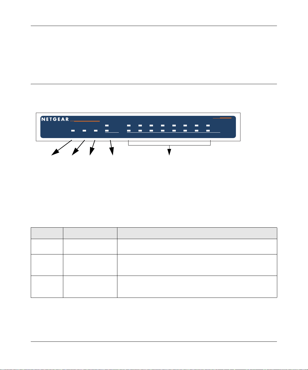
The Router’s Front Panel
The FVS338 ProSafe VPN Firewall 50 front panel shown below contains the status LEDs.
Power
LED
Test
LED
Modem
LED
Internet
LEDs
Local
LEDs
Figure 2-1: FVS338 Front Panel
You can use the LEDs to verify various conditions. Table 2-1 lists and describes each object on the
front panel of the router and its operation.
Table 2-1. Object Descriptions
Object Activity Description
Power LED On (Green)
Off
Test LED On (Amber)
Blinking (Amber)
Off
MDM LED On (Green)
Blinking (Green)
Off
Power is supplied to the router.
Power is not supplied to the router.
Test mode: The system is initializing or the initialization has failed.
Writing to Flash memory (during upgrading or resetting to defaults).
The system has booted successfully.
The serial port detected a link with an attached modem.
Server data is being transmitted or received by the serial port.
The serial port has no link.
2-6 Introduction
January 2005
Reference Manual for the ProSafe VPN Firewall 50 FVS338
Table 2-1. Object Descriptions (continued)
Object Activity Description
Internet
LEDs
Link/Act LED
On (Green)
Blinking (Green)
Off
The WAN port has detected a link with a connected Ethernet device.
Data is being transmitted or received by the WAN port.
The WAN port has no link.
100 LED
On (Green)
Off
The WAN port is operating at 100 Mbps.
The WAN port is operating at 10 Mbps.
Local LEDs Link/Act LED
On (Green)
Blinking (Green)
Off
The LAN port has detected a link with a connected Ethernet device.
Data is being transmitted or received by the LAN port.
The LAN port has no link.
100 LED
On (Green)
Off
The LAN port is operating at 100 Mbps.
The LAN port is operating at 10 Mbps.
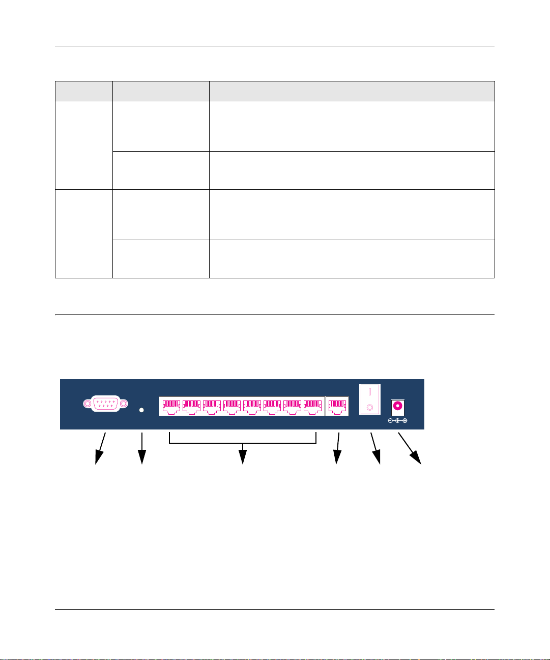
The Router’s Rear Panel
The rear panel of the FVS338 ProSafe VPN Firewall 50 (Figure 2-1) contains the port
connections, modem connector , factory defaults button, On/Off switch, and DC power connection.
LOCAL
FACTORY
DEFAULTS
5
678MODEM
INTERNET
1234
12VDC 1.2A
Modem
Port
Factory
Defaults
Local
Ports
Internet
Port
On/Off
Switch
DC Power
Connection
Button
Figure 2-2: FVS338 Rear Panel
Viewed from left to right, the rear panel contains the following elements:
• Modem port — serves as the WAN2 Internet port through the public switched telephone
network (PSTN).
• Factory Defaults push button — see “Default Factory Settings” on page 2-9.
Introduction 2-7
January 2005
Reference Manual for the ProSafe VPN Firewall 50 FVS338
• Local ports — 8-port RJ-45 10/100 Mbps Fast Ethernet Switch, N-way automatic speed
negotiation, auto MDI/MDIX.
• Internet port — serves as the WAN1 Internet port. One RJ-45 WAN port, N-way automatic
speed negotiation, Auto MDI/MDIX.
•On/Off switch
• DC power in (12 VDC, 1.2A)
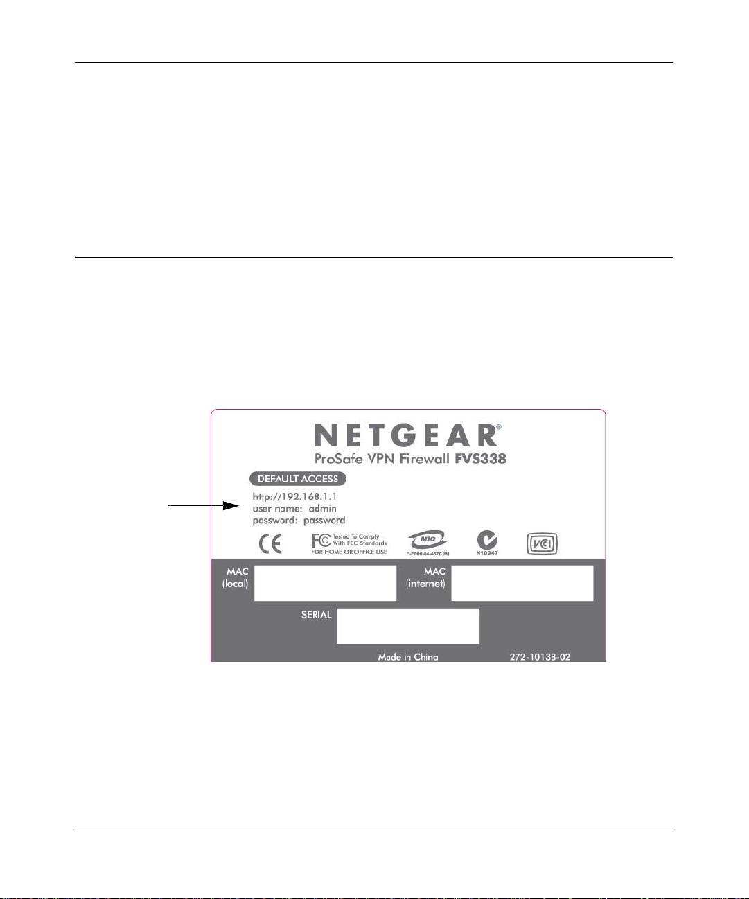
The Router’s IP Address, Login Name, and Password
Check the label on the bottom of the FVS338’s enclosure if you forget the following factory
default information:
• IP Address: http://192.168.1.1 to reach the Web-based GUI from the LAN
•User name: admin
• Password: password
LAN IP Address
User Name
Password
Figure 2-3: FVS338 Bottom Label
2-8 Introduction
January 2005

Reference Manual for the ProSafe VPN Firewall 50 FVS338
Default Factory Settings
When you first receive your FVS338, the default factory settings will be set as shown in Ta ble 2-2
below . You can restore these defaults with the Factory Defaults restore switch on the rear panel —
see “The Router’s Rear Panel” on page 2-7.
• Pressing this switch for a prolonged period (>10 seconds; until the EST LED begins to blink)
causes the router to restore all factory default settings and reboot.
• A shorter press and release causes the router to merely reboot.
Table 2-2. Factory Default Settings
Feature Default
User Name (case sensitive) admin
Password (case sensitive) password
Built-in DHCP server DHCP server enabled, issues addresses in the
default subnet
IP Configuration IP Address: 192.168.1.1
Subnet Mask: 255.255.255.0
Time Zone GMT
Time Zone Adjust for Daylight Saving TIme Disabled
SNMP Disabled
NETGEAR Related Products
NETGEAR products related to the FVS338 ProSafe VPN Firewall 50 are as follows:
• FA311 10/100 PCI Adapter
• FA511 10/100 32-bit CardBus Adapter
• GA311 10/100/1000 PCI Adapter
• FVL328 ProSafe VPN Firewall
• FVS318 ProSafe VPN Firewall 8
• FVX538 ProSafe VPN Firewall 200
• FWG114P ProSafe 802.11g Wireless Firewall with USB Print Server
• NMS100 ProSafe Network Management System
Introduction 2-9
January 2005

Reference Manual for the ProSafe VPN Firewall 50 FVS338
• VPN01L and VPN05L ProSafe VPN Client Software
• WG302 ProSafe 802.11g Access Point
2-10 Introduction
January 2005
Reference Manual for the ProSafe VPN Firewall 50 FVS338
Chapter 3
Network Planning
This chapter describes the factors to consider when planning a network using a router that has dual
WAN ports.
Overview of the Planning Process
The areas that require planning when using a router that has dual WAN ports include:
• Single or multiple exposed hosts
• Virtual private networks (VPNs)
The two WAN ports can be configured to fail over for increased system reliability.
Note: Exposed hosts are sometimes referred to as DMZ hosts. Unlike hardware-based
DMZ ports, however, exposed hosts are implemented in software and do not enjoy the
same level of firewall protection that hardware-based DMZ ports do. Use the exposed
host feature at your own risk.
Single or Multiple Exposed Hosts
Unrequested incoming traffic can be directed to one or more exposed hosts rather than being
discarded. As a result, the IP address of at least one WAN port must always be public.
The mechanism for making the IP address public depends on whether there are single or multiple
exposed hosts and whether the dual WAN ports are configured to either fail over or balance the
loads. See “Single or Multiple Exposed Hosts” on page 3-2 for further discussion.
Virtual Private Networks (VPNs)
A virtual private network (VPN) tunnel provides a secure communication channel between either
two gateway VPN routers or between a remote PC client and gateway VPN router. As a result, the
IP address of at least one of the tunnel end points must be known in advance in ord e r for the o t her
tunnel end point to establish (or re-establish) the VPN tunnel. See “Virtual Private Networks
(VPNs)” on page 3-5 for further discussion.
Network Planning 3-1
January 2005
Reference Manual for the ProSafe VPN Firewall 50 FVS338
Note: Once the gateway router WAN port fails over, the VPN tunnel collapses and must
be re-established using the new WAN IP address.
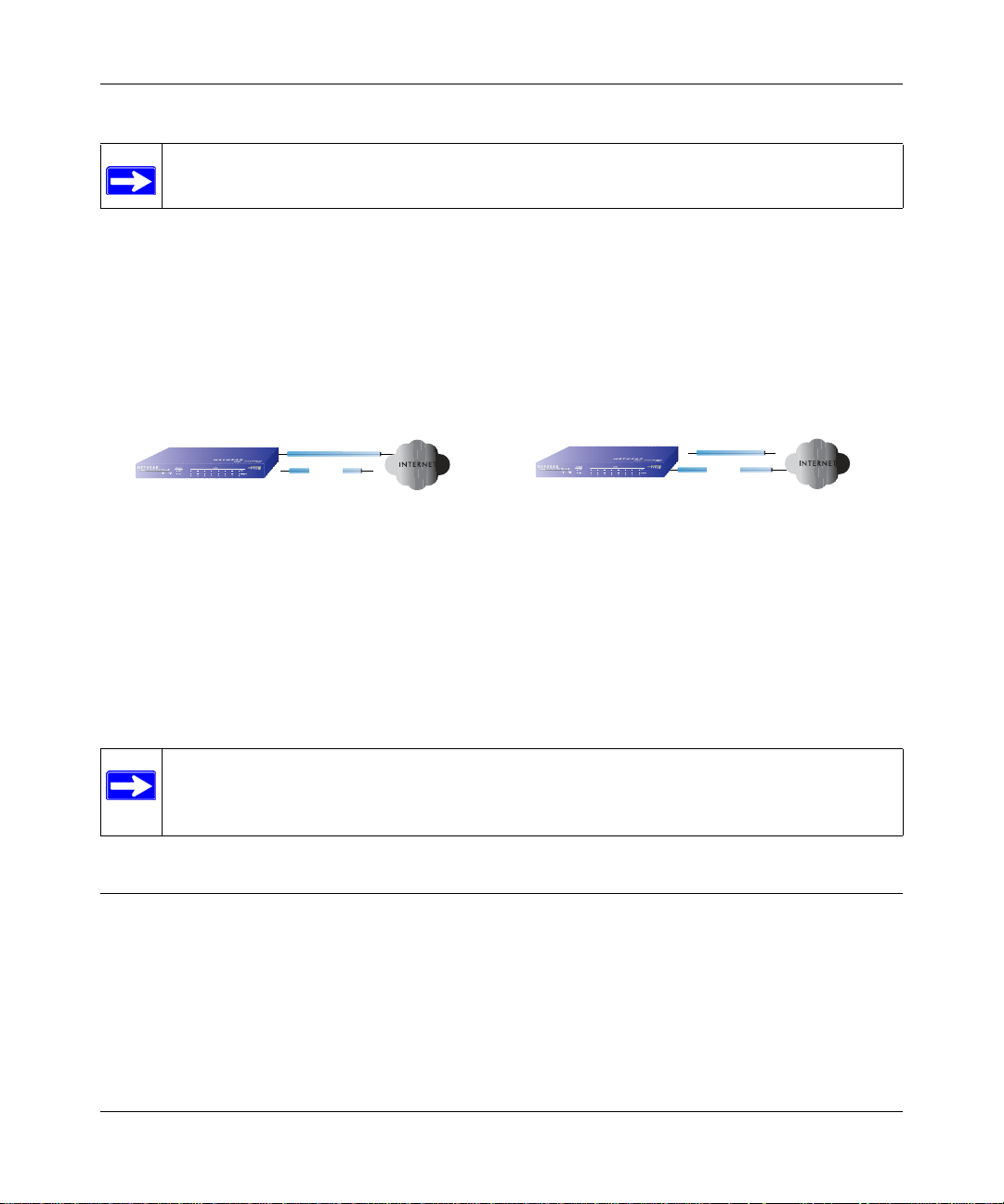
The Fail-over Case for Routers With Dual WAN Ports
Failover (Figure 3-1) for the dual WAN port case is different from the single gateway WAN port
case when specifying the IP address. Only one WAN port is active at a time and when it fails over,
the IP address of the active WAN port always changes. Hence, the use of a fully-qualified domain
name is always required, even when the IP address of each WAN port is fixed.
Dual WAN Ports (Before Failover)
Router
IP address of active WAN port changes after a failover:
o use of fully-qualified domain names always required
o features requiring fixed IP address blocks not supported
WAN1 IP
WAN1 port active
PSTN
X
WAN2 port inactive
WAN2 IP (N/A)
X
Dual WAN Ports (After Failover)
Router
WAN1 IP (N/A)
WAN1 port inactive
XX
PSTN
WAN2 port active
WAN2 IP
Figure 3-1: Dual WAN ports before and after failover
Features such as multiple exposed hosts are not supported in general when using dual WAN port
failover because the IP addresses of each WAN port must be in the identical range of fixed
addresses.
Note: In certain locales, an ISP has been able to provision the same IP address for the
broadband and PSTN service so that the failover to a serial connection would be as
seamless as possible.
Single or Multiple Exposed Hosts
Incoming traffic from the Internet is normally discarded by the firewall unless the traffic is a
response to one of your local computers or a service that you have configured in the Incoming
Rules menu. Instead of discarding this traffic, yo u can have it forwarded to one or more LAN hosts
on your network. These LAN hosts are called exposed hosts. The addressing of the router’s dual
WAN port depends on the configuration being implemented:
3-2 Network Planning
January 2005

Reference Manual for the ProSafe VPN Firewall 50 FVS338
Table 3-1. IP addressing requirements for exposed hosts in dual WAN port systems
Configuration and
WAN IP address
Single exposed host Fixed Allowed
Dynamic FQDN required FQDN required
Multiple exposed hosts Fixed Address block required Not allowed
Dynamic Not allowed Not allowed
*. Not allowed because to do so, the IP addresses of each WAN port would have to be the identical range of fixed
addresses. In certain locales, however, an ISP has been able to provision the same IP address for the broadband and PSTN service so that the failover to a serial connection would be as seamless as possible.
Single WAN Port
(reference case)
(FQDN optional)
Dual WAN Port Case
Failover
FQDN required
*
Single Exposed Host
The Internet IP address of the router’s WAN port must be public so that the public can send
incoming traffic to the exposed host when this feature is supported and enabled.
Single Exposed Host: Single WAN Port (Reference Case)
In the single WAN case (Figure 3-2), the WAN’s Internet address is either fixed IP or a
fully-qualified domain name if the IP address is dynamic.
Router
WAN IP
exposed host
netgear.dyndns.org
IP address of WAN port:
FQDN is required for dynamic IP address and is optional for fixed IP address
Figure 3-2: Single WAN port case with exposed host
Single Exposed Host: Dual WAN Ports for Improved System Reliability
In the dual WAN port case with failover (Figure 3-3), the WAN’s IP address will always change at
failover. A fully-qualified domain name must be used that toggles between the IP addresses of the
WAN ports (i.e., WAN1 or WAN2).
Network Planning 3-3
January 2005

Reference Manual for the ProSafe VPN Firewall 50 FVS338
Dual WAN Ports (Before Failover)
Router
exposed host
IP address of active WAN port changes after a failover (use of fully-qualified domain names always required)
WAN1 IP
netgear.dyndns.org
PSTN
XX
WAN2 port inactive
WAN2 IP (N/A)
Dual WAN Ports (After Failover)
Router
exposed host
WAN1 IP (N/A)
WAN1 port inactive
XX
PSTN
netgear.dyndns.org
WAN2 IP
Figure 3-3: Dual WAN port case with exposed host, before and after failover
Multiple Exposed Hosts
The IP address range of the router’s WAN port must be both fixed and public so that the public can
send incoming traffic to the multiple exposed hosts when this feature is supported and enabled.
Multiple Exposed Hosts: Single WAN Port (Reference Case)
In the single WAN case (Figure 3-4), the WAN port’s IP address range must be fixed.
Single WAN Port
Router
exposed hosts
WAN IPs
22.23.24.25
22.23.24.26
...
IP addresses of WAN port must be a fixed block
Figure 3-4: Single WAN port case with multiple exposed hosts
Multiple Exposed Hosts: Dual WAN Ports for Improved System Reliability
Using multiple exposed hosts with routers that have dual WAN ports for improved system
reliability is a disallowed combination because to do so, the IP addresses of each W AN port would
have to be the identical range of fixed addresses. Instead, use additional routers that have dual
WAN ports with a single exposed host for improved system reliability.
Note: In certain locales, an ISP has been able to provision the same IP address for the
broadband and PSTN service so that the failover to a serial connection would be as
seamless as possible.
3-4 Network Planning
January 2005

Reference Manual for the ProSafe VPN Firewall 50 FVS338
Virtual Private Networks (VPNs)
When implementing virtual private network (VPN) tunnels, a mechanism must be used for
determining the IP addresses of the tunnel end points. The addressing of the router’s dual WAN
port depends on the configuration being implemented:
Table 3-1. IP addressing requirements for VPNs in dual WAN port systems
Single WAN Port
Configuration and WAN IP address
VPN Road Warrior
(client-to-gateway)
VPN Gateway-to-Gateway Fixed Allowed
VPN Telecommuter
(client-to-gateway through a NAT
router)
*. All tunnels must be re-established after a failover using the new WAN IP address.
Fixed Allowed
Dynamic FQDN required FQDN required
Dynamic FQDN required FQDN required
Fixed Allowed
Dynamic FQDN required FQDN required
(reference case)
(FQDN optional)
(FQDN optional)
(FQDN optional)
Dual WAN Port Case
Failover
FQDN required
FQDN required
FQDN required
*
For the single gateway WAN port case, the mechanism is to use a fully-qualified domain name
(FQDN) when the IP address is dynamic and to use either an FQDN or the IP address itself when
the IP address is fixed. The situation is different when dual gateway WAN ports are used in a
failover-based system.
Failover (Figure 3-5) for the dual gateway WAN port case is different from the single gateway
WAN port case when specifying the IP address of the VPN tunnel end point. Only one WAN port
is active at a time and when it fails over, the IP address of the active WAN port always changes.
Hence, the use of a fully-qualified domain name is always required, even when the IP address of
each WAN port is fixed.
Note: Once the gateway router WAN port fails over, the VPN tunnel collapses and must
be re-established using the new WAN IP address.
Network Planning 3-5
January 2005

Reference Manual for the ProSafe VPN Firewall 50 FVS338
Dual WAN Ports (Before Failover)
Gateway
VPN Router
IP address of active WAN port changes after a failover (use of fully-qualified domain names always required)
WAN1 IP
netgear.dyndns.org
PSTN
XX
WAN2 port inactive
WAN2 IP (N/A)
Dual WAN Ports (After Failover)
Gateway
VPN Router
WAN1 IP (N/A)
WAN1 port inactive
XX
PSTN
netgear.dyndns.org
WAN2 IP
Figure 3-5: Dual gateway WAN ports before and after failover
VPN Road Warrior (Client-to-Gateway)
The following situations exemplify the requirements for a remote PC client with no router to
establish a VPN tunnel with a gateway VPN router:
• Single gateway WAN port
• Redundant dual gateway WAN ports for increased system reliability (before and after failover)
VPN Road Warrior: Single Gateway WAN Port (Reference Case)
In the case of the single WAN port on the gateway VPN router (Figure 3-6), the remote PC client
initiates the VPN tunnel because the IP address of the remote PC client is not known in advance.
The gateway WAN port must act as the responder.
10.5.6.0/24
Client B
Remote PC
(running NETGEAR
ProSafe VPN Client)
LAN IP
10.5.6.1
Road Warrior Example (Single WAN Port)
Gateway A
VPN Router
(at employer's
main office)
Fully-Qualified Domain Names (FQDN)
- optional for Fixed IP addresses
- required for Dynamic IP addresses
WAN IP
FQDN
bzrouter.dyndns.org
WAN IP
0.0.0.0
Figure 3-6: Single gateway WAN port case for VPN road warrior
The IP address of the gateway WAN port can be either fixed or dynamic. If the IP address is
dynamic, a fully-qualified domain name must be used. If the IP address is fixed, a fully-qualified
domain name is optional.
3-6 Network Planning
January 2005

Reference Manual for the ProSafe VPN Firewall 50 FVS338
VPN Road Warrior: Dual Gateway WAN Ports for Improved System Reliability
In the case of the dual WAN ports on the gateway VPN router (Figure 3-7), the remote PC client
initiates the VPN tunnel with the active gateway WAN port (port WAN1 in this example) because
the IP address of the remote PC client is not known in advance. The gateway WAN port must act
as a responder.
10.5.6.0/24
LAN IP
10.5.6.1
Road Warrior Example
(Dual WAN Ports, Before Failover)
Gateway A
VPN Router
(at employer's
main office)
Fully-Qualified Domain Names (FQDN)
- required for Fixed IP addresses
- required for Dynamic IP addresses
WAN1 IP
bzrouter.dyndns.org
X
PSTN
WAN2 port inactive
WAN2 IP (N/A)
Client B
WAN IP
X
0.0.0.0
Remote PC
(running NETGEAR
ProSafe VPN Client)
Figure 3-7: Dual gateway WAN ports, before failover, for VPN road warrior
The IP addresses of the gateway WAN ports can be either fixed or dynamic, but a fully-qualified
domain name must always be used because the active WAN port could be either WAN1 or WAN2
(i.e., the IP address of the active WAN port is not known in advance).
After a failover of the gateway WAN port (Figure 3-8), the previously inactive gateway W AN port
becomes the active port (port WAN2 in this example) and the remote PC client must re-establish
the VPN tunnel. The gateway WAN port must act as the responder.
Note: Since WAN2 is dial-up, it must be connected before the client can initiate the VPN
tunnel.
Network Planning 3-7
January 2005

Reference Manual for the ProSafe VPN Firewall 50 FVS338
10.5.6.0/24
LAN IP
10.5.6.1
Road Warrior Example
(Dual WAN Ports, After Failover)
Gateway A
VPN Router
(at employer's
main office)
Remote PC must re-establish VPN tunnel after a failover
WAN1 IP (N/A)
WAN1 port inactive
XX
Fully-Qualified Domain Names (FQDN)
- required for Fixed IP addresses
- required for Dynamic IP addresses
PSTN
bzrouter.dyndns.org
WAN2 IP
Client B
WAN IP
0.0.0.0
Remote PC
(running NETGEAR
ProSafe VPN Client)
Figure 3-8: Dual gateway W AN ports, after failover, for VPN road warrior
The purpose of the fully-qualified domain name is this case is to toggle the domain name of the
gateway router between the IP addresses of the active WAN port (i.e., WAN1 and WAN2) so that
the remote PC client can determine the gateway IP address to establish or re-establish a VPN
tunnel.
VPN Gateway-to-Gateway
The following situations exemplify the requirements for a gateway VPN router to establish a VPN
tunnel with another gateway VPN router:
• Single gateway WAN ports
• Redundant dual gateway WAN ports for increased system reliability (before and after failover)
VPN Gateway-to-Gateway: Single Gateway WAN Ports (Reference Case)
In the case of single WAN ports on the gateway VPN routers (Figure 3-9), either gateway WAN
port can initiate the VPN tunnel with the other gateway WAN port because the IP addresses are
known in advance.
3-8 Network Planning
January 2005

Reference Manual for the ProSafe VPN Firewall 50 FVS338
10.5.6.0/24
172.23.9.0/24
Gateway-to-Gateway Example (Single WAN Ports)
LAN IP
10.5.6.1
Gateway A
VPN Router
(at office A)
WAN IP
FQDN
netgear.dyndns.org
Fully-Qualified Domain Names (FQDN)
- optional for Fixed IP addresses
- required for Dynamic IP addresses
WAN IP
22.23.24.25
Gateway B
LAN IP
172.23.9.1
VPN Router
(at office B)
Figure 3-9: Single gateway WAN ports case for gateway-to-gateway VPN tunnels
The IP address of the gateway WAN ports can be either fixed or dynamic. If an IP address is
dynamic, a fully-qualified domain name must be used. If an IP address is fixed, a fully-qualified
domain name is optional.
VPN Gateway-to-Gateway: Dual Gateway WAN Ports for Improved System Reliability
In the case of the dual WAN ports on the gateway VPN router (Figure 3-10), either of the gateway
WAN ports at one end can initiate the VPN tunnel with the appropriate gateway WAN port at the
other end as necessary to balance the loads of the gateway WAN ports because the IP addresses of
the WAN ports are known in advance. In this example, port WAN_A1 is active and port WAN_A2
is inactive at Gateway A; port WAN_B1 is active and port WAN_B2 is inactive at Gateway B.
10.5.6.0/24
Gateway-to-Gateway Example
172.23.9.0/24
(Dual WAN Ports, Before Failover)
LAN IP
10.5.6.1
Gateway A
VPN Router
(at office A)
WAN_A1 IP
netgearA.dyndns.org
PSTN
XX
WAN_A2 port inactive
WAN_A2 IP (N/A)
Fully-Qualified Domain Names (FQDN)
- required for Fixed IP addresses
- required for Dynamic IP addresses
WAN_B1 IP
netgearB.dyndns.org
PSTN
XX
WAN_B2 port inactive
WAN_B2 IP (N/A)
Gateway B
LAN IP
172.23.9.1
VPN Router
(at office B)
Figure 3-10: Dual gateway WAN ports, before failover, for gateway-to-gateway VPN tunnels
Network Planning 3-9
January 2005

Reference Manual for the ProSafe VPN Firewall 50 FVS338
The IP addresses of the gateway WAN ports can be either fixed or dynamic, but a fully-qualified
domain name must always be used because the active WAN ports could be either WAN_A1,
WAN_A2, WAN_B1, or WAN_B2 (i.e., the IP address of the active WAN port is not known in
advance).
After a failover of a gateway WAN port (Figure 3-11), the previously inactive gateway WAN port
becomes the active port (port WAN_A2 in this example) and one of the gateway VPN routers must
re-establish the VPN tunnel.
10.5.6.0/24
Gateway-to-Gateway Example
172.23.9.0/24
(Dual WAN Ports, After Failover)
LAN IP
10.5.6.1
Gateway A
VPN Router
(at office A)
One of the gateway routers must re-establish VPN tunnel after a failover
WAN_A1 IP (N/A)
WAN_A1 port inactive
XX
PSTN
netgear.dyndns.org
WAN_A2 IP
Fully-Qualified Domain Names (FQDN)
- required for Fixed IP addresses
- required for Dynamic IP addresses
WAN_B1 IP
netgearB.dyndns.org
PSTN
XX
WAN_B2 port inactive
WAN_B2 IP (N/A)
Gateway B
LAN IP
172.23.9.1
VPN Router
(at office B)
Figure 3-11: Dual gateway WAN ports, after failover, for gateway-to-gateway VPN tunnels
The purpose of the fully-qualified domain names is this case is to toggle the domain name of the
failed-over gateway router between the IP addresses of the active WAN port (i.e., WAN_A1 and
WAN _A2 in this example) so that the other end of the tunnel has a known gateway IP address to
establish or re-establish a VPN tunnel.
VPN Telecommuter (Client-to-Gateway Through a NAT Router)
Note: The telecommuter case presumes the home office has a dynamic IP address and
NAT router for budgetary reasons.
The following situations exemplify the requirements for a remote PC client connected to the
Internet with a dynamic IP address through a NAT router to establish a VPN tunnel with a gateway
VPN router at the company office:
• Single gateway WAN port
• Redundant dual gateway WAN ports for increased system reliability (before and after failover)
3-10 Network Planning
January 2005

Reference Manual for the ProSafe VPN Firewall 50 FVS338
VPN Telecommuter: Single Gateway WAN Port (Reference Case)
In the case of the single WAN port on the gateway VPN router (Figure 3-12), the remote PC client
at the NAT router initiates the VPN tunnel because the IP address of the remote NAT router is not
known in advance. The gateway WAN port must act as the responder.
10.5.6.0/24
Telecommuter Example (Single WAN Port)
Client B
NAT Router B
NATRouter
(at telecommuter's
home office)
Remote PC
(running NETGEAR
ProSafe VPN Client)
LAN IP
10.5.6.1
Gateway A
VPN Router
(at employer's
main office)
WAN IP
FQDN 0.0.0.0
bzrouter.dyndns.org
Fully-Qualified Domain Names (FQDN)
- optional for Fixed IP addresses
- required for Dynamic IP addresses
WAN IP
Figure 3-12: Single gateway WAN port case for VPN telecommuter
The IP address of the gateway WAN port can be either fixed or dynamic. If the IP address is
dynamic, a fully-qualified domain name must be used. If the IP address is fixed, a fully-qualified
domain name is optional.
VPN Telecommuter: Dual Gateway WAN Ports for Improved System Reliability
In the case of the dual WAN ports on the gateway VPN router (Figure 3-13), the remote PC client
initiates the VPN tunnel with the active gateway WAN port (port WAN1 in this example) because
the IP address of the remote NAT router is not known in advance. The gateway W AN port must act
as the responder.
10.5.6.0/24
Figure 3-13: Dual gateway WAN ports, before failover, for VPN telecommuter
Network Planning 3-11
Telecommuter Example
(Dual WAN Ports, Before Failover)
Gateway A
LAN IP
10.5.6.1
VPN Router
(at employer's
main office)
WAN1 IP
bzrouter1.dyndns.org
X
WAN2 port inactive
WAN2 IP (N/A)
Fully-Qualified Domain Names (FQDN)
- required for Fixed IP addresses
- required for Dynamic IP addresses
PSTN
WAN IP
X
January 2005
0.0.0.0
NAT Router B
NATRouter
(at telecommuter's
home office)
Client B
Remote PC
(running NETGEAR
ProSafe VPN Client)

Reference Manual for the ProSafe VPN Firewall 50 FVS338
The IP addresses of the gateway WAN ports can be either fixed or dynamic, but a fully-qualified
domain name must always be used because the active WAN port could be either WAN1 or WAN2
(i.e., the IP address of the active WAN port is not known in advance).
After a failover of the gateway WAN port (Figure 3-14), the previously inactive gateway WAN
port becomes the active port (port WAN2 in this example) and the remote PC must re-establish the
VPN tunnel. The gateway WAN port must act as the responder.
Note: Since WAN2 is dial-up, it must be connected before the client can initiate the VPN
tunnel.
10.5.6.0/24
Telecommuter Example
(Dual WAN Ports, After Failover)
Client B
LAN IP
10.5.6.1
Gateway A
VPN Router
(at employer's
main office)
WAN1 IP (N/A)
WAN1 port inactive
XX
PSTN
bzrouter2.dyndns.org
WAN2 IP
Fully-Qualified Domain Names (FQDN)
- required for Fixed IP addresses
- required for Dynamic IP addresses
Remote PC must re-establish VPN tunnel after a failover
WAN IP
0.0.0.0
NAT Router B
NATRouter
(at telecommuter's
home office)
Remote PC
(running NETGEAR
ProSafe VPN Client)
Figure 3-14: Dual gateway WAN ports, after failover, for VPN telecommuter
The purpose of the fully-qualified domain name is this case is to toggle the domain name of the
gateway router between the IP addresses of the active WAN port (i.e., WAN1 and WAN2) so that
the remote PC client can determine the gateway IP address to establish or re-establish a VPN
tunnel.
3-12 Network Planning
January 2005

Chapter 4
Connecting the FVS338 to the Internet
This chapter describes how to set up the firewall on your Local Area Network (LAN) and connect
to the Internet. You can perform basic configuration of your FVS338 ProSafe VPN Firewall 50
using the Setup Wizard, or manually configure your Internet connection.
What You Will Need Before You Begin
You need to prepare these three things before you can connect your VPN firewall to the Internet:
1. A computer properly connected to the VPN firewall as explained below.
2. Active Internet service such as that provided by a DSL or Cable modem account.
3. The Internet Service Provider (ISP) configuration information for your account.
LAN Hardware Requirements
T o use the FVS338 VPN firewall on your network, each computer must have an installed Ethernet
Network Interface Card (NIC) and an Ethernet cable. If the computer will connect to your network
at 100 Mbps, you must use a Category 5 (CAT 5) cable such as the one provided with your VPN
firewall.
The broadband modem must provide a standard 10 Mbps 10BASE-T or 100 Mbps 100BASE-T
Ethernet interface.
LAN Configuration Requirements
For the initial connection to the Internet and configuration of your VPN firewall, you will need to
connect a computer to the VPN firewall which is set to automatically get its TCP/IP configuration
from the VPN firewall via DHCP. The computer you use must have a Web browser such as
Internet Explorer v5 or greater or Netscape Communicator v4.7 or greater.
Note: Please refer to Appendix C, “Preparing Your Network for assistance with DHCP
configuration.
Connecting the FVS338 to the Internet 4-1
January 2005

Reference Manual for the ProSafe VPN Firewall 50 FVS338
Internet Configuration Requirements
Depending on how your ISP or IT group set up your Internet access, you will need one or more of
these configuration parameters to connect your VPN firewall to the Internet:
• Host and Domain Names
• ISP Login Name and Password
• ISP Domain Name Server (DNS) Addresses
• Fixed or Static IP Address
Where Do I Get the Internet Configuration Parameters?
There are several ways you can gather the required Internet connection information.
• Your ISP should have provided you with all the information needed to connect to the Internet.
If you cannot locate this information, you can ask your ISP to provide it or you can try one of
the options below.
• If you have a computer already connected using the active Internet access account, you can
gather the configuration information from that computer.
• For Windows 95/98/Me, open the Network control panel, select the TCP/IP entry for the
Ethernet adapter, and click Properties.
• For Windows 2000/XP, open the Local Area Network Connection, select the TCP/IP entry
for the Ethernet adapter, and click Properties.
• For Macintosh computers, open the TCP/IP or Network control panel.
• You may also refer to the FVS338 Resource CD for the NETGEAR Router ISP Guide which
provides Internet connection information for many ISPs.
Once you locate your Internet configuration parameters, you may want to record them on the page
below according to the instructions in “Worksheet for Recording Your Internet Connection
Information” on page 4-3.
4-2 Connecting the FVS338 to the Internet
January 2005

Reference Manual for the ProSafe VPN Firewall 50 FVS338
Worksheet for Recording Your Internet Connection Information
Print this page. Fill in the configuration parameters from your Internet Service Provider (ISP).
ISP Login Name: The login name and password are case sensitive and must be entered exactly as
given by your ISP. Some ISPs use your full e-mail address as the login name. The Service Name is
not required by all ISPs. If you connect using a login name and password, then fill in the
following:
Login Name: ________________________
Password: ______________________
Service Name: ________________________
Fixed or Static IP Address: If you have a static IP address, record the following information. For
example, 169.254.141.148 could be a valid IP address.
Fixed or Static Internet IP Address: ______
.______.______.______
Subnet Mask: ______.______.______.______
Gateway IP Address: ______.______.______.______
ISP DNS Server Addresses: If you were given DNS server addresses, fill in the following:
Primary DNS Server IP Address: ______
.______.______.______
Secondary DNS Server IP Address: ______.______.______.______
Host and Domain Names: Some ISPs use a specific host or domain name like CCA7324-A or
home. If you haven’t been given host or domain names, you can use the following examples as a
guide:
• If your main e-mail account with your ISP is
aaa@yyy.com, then use aaa as your host name.
Your ISP might call this your account, user, host, computer, or system name.
• If your ISP’s mail server is
ISP Host Name: __________________
mail.xxx.yyy.com, then use xxx.yyy.com as the domain name.
ISP Domain Name: ___________________
For Serial Port Internet Access: If you use a dial-up account, record the following:
Account/User Name: ___________________
Password: ____________________
Telephone number: _________________ Alternative number: _________________
Fully Qualified Domain Name: Some organizations use a fully qualified domain name (FQDN)
from a dynamic DNS service provider for their IP addresses.
Dynamic DSN Service Provider: ______________________
Connecting the FVS338 to the Internet 4-3
January 2005
FQDN: _______________________

Reference Manual for the ProSafe VPN Firewall 50 FVS338
Connecting the FVS338 to Your LAN
This section provides instructions for connecting the FVS338 ProSafe VPN Firewall 50 to your
Local Area Network (LAN).
Note: The Resource CD included with your VPN firewall contains an animated Installation
Assistant to help you through this procedure.
How to Connect the FVS338 to Your LAN
There are three steps to connecting your firewall:
• Connect the VPN firewall to your network.
• Log in to the VPN firewall.
• Connect to the Internet.
Follow the steps below to connect your VPN firewall to your network.
1. Connect the FVS338.
a. Turn off your computer and cable or DSL modem.
b. Disconnect the Ethernet cable (A) from your computer which connects to yo ur cable or
DSL modem.
c. Connect the Ethernet cable (A) from your cable or DSL modem to the FVS338’s Internet
port.
d. Connect the Ethernet cable (B) which came with the VPN firewall from a Local port on
the router to your computer.
TM
Note: The FVS338 VPN firewall incorporates Auto Uplink
technology. Each Ethernet
port will automatically sense whether the cable plugged into the port should have a
'normal' connection (e.g. connecting to a PC) or an 'uplink' connection (e.g. connecting to
a switch or hub). That port will then configure itself to the correct configuration. This
feature also eliminates the need to worry about crossover cables, as Auto Uplink will
accommodate either type of cable to make the right connection.
e. Turn on the cable or DSL modem and wait about 30 seconds for the lights to stop blinking.
4-4 Connecting the FVS338 to the Internet
January 2005

Reference Manual for the ProSafe VPN Firewall 50 FVS338
2. Log in to the FVS338.
Note: To connect to the VPN firewall, your computer needs to be configured to obtain an
IP address automatically via DHCP. Please refer to Appendix C, “Preparing Y our Network
for instructions on how to do this.
a. Turn on the VPN firewall and wait for the TEST light to stop blinking.
b. Now, turn on your computer.
Note: If you usually run software to log in to your Internet connection, do not run that
software.
Now that the cable or DSL modem, VPN firewall, and the computer are turned on, verify
the following:
– When power on the VPN firewall was first turned on, the PWR light went on, the
TEST light turned on within a few seconds, and then went off after approximately 10
seconds.
– The VPN firewall’s LOCAL LINK/ACT lights are lit for any computers that are
connected to it.
– The VPN firewall’s INTERNET LINK light is lit, indicating a link has been
established to the cable or DSL modem.
c. Next, use a browser like Internet Explorer or Netscape to log in to the VPN firewall at its
default address of http://192.168.1.1. A login window opens.
d. For security reasons, the VPN firewall has its own user name and password. When
prompted, enter
admin for the VPN firewall User Name and password for the VPN
firewall Password, both in lower case letters. This default password should be changed
later, as described in “Changing the Administrator Password and Login Timeout” on
page 9-8.
Note: The user name and password are not the same as any user name or password you
may use to log in to your Internet connection.
Connecting the FVS338 to the Internet 4-5
January 2005

Reference Manual for the ProSafe VPN Firewall 50 FVS338
Connect to the Internet.
3.
Figure 4-1: Setup Wizard
a.
You are now connected to the VPN firewall. If you do not see the menu above, click the
Setup Wizard link on the upper left of the main menu.
b. Choose NAT or Classical Routing. NAT automatically assigns private IP addresses
(192.168.0.x) to LAN connected devices. Classical routing lets you directly manage the IP
addresses the FVS338 uses. Classical routing should be selected only by experienced
users.
c. Click Next and follow the steps in the Setup Wizard for inputting the configuration
parameters from your ISP to connect to the Internet.
Note: If you choose not to use the Setup Wizard, you can manually configure your
Internet connection settings by following the procedure “Manually Configuring Your
Internet Connection” on page 4-14.
Unless your ISP automatically assigns your configuration automatically via DHCP, you
will need the configuration parameters from your ISP as you recorded them previously in
“Worksheet for Recording Your Internet Connection Information” on page 4-3
d. When the VPN firewall successfully detects an active Internet service, the VPN firewall’s
Internet LED goes on. The Setup Wizard reports which connection type it discovered, and
displays the appropriate configuration menu. If the Setup W izard finds no connection, you
will be prompted to check the physical connection between your VPN firewall and the
cable or DSL line.
e. The Setup Wizard will report the type of connection it finds. The options are:
4-6 Connecting the FVS338 to the Internet
January 2005

Reference Manual for the ProSafe VPN Firewall 50 FVS338
• Connections that require a login using protocols such as PPPoE, Telstra BigPond, or
PPTP broadband Internet connections.
• Connections that use dynamic IP address assignment.
• Connections that use fixed IP address assignment.
The procedures for filling in the configuration menu for each type of connection follow
below.
Configuring for a Wizard-Detected Login Account
If the Setup Wizard determines that your Internet service account uses a login protocol such as
PPP over Ethernet (PPPoE), you will be directed to the correct setup menu.
1. Enter your Account Name (may also be called Host Name) and Domain Name. These
parameters may be necessary to access your ISP’s services such as mail or news servers. If you
leave the Domain Name field blank, the VPN firewall will attempt to learn the domain
automatically from the ISP. If this is not successful, you may need to enter it manually.
2. Enter the PPPoE login user name and password provided by your ISP. These fields are case
sensitive. If you want to change the login timeout, enter a new value in minutes.
Note: You will no longer need to launch the ISP’s login program on your computer in order to
access the Internet. When you start an Internet application, the VPN firewall will
automatically log you in.
3. Enable or disable NAT (Network Address Translation). NAT allows all LAN computers to
gain Internet access via this Router, by sharing this Router's WAN IP address. In most
situations, NAT is essential for Internet access via this Router. You should only disable NA T if
you are sure you do not require it. When NAT is disabled, only standard routing is performed
by this Router.
4. Perform a DNS Lookup. A DNS (Domain Name Server) converts the Internet name (e.g.
www.netgear.com) to an IP address. If you need the IP address of a Web, FTP, Mail or other
Server on the Internet, you can do a DNS lookup to find the IP address.
Domain Name Server (DNS) Address: If you know that your ISP does not automatically
transmit DNS addresses to the VPN firewall during login, select “Use these DNS servers” and
enter the IP address of your ISP’s Primary DNS Server. If a Secondary DNS Server address is
available, enter it also.
If you enter an address here, after you finish configuring the VPN firewall, reboot your
computers so that the settings take effect.
Connecting the FVS338 to the Internet 4-7
January 2005

Reference Manual for the ProSafe VPN Firewall 50 FVS338
Enter the Router's MAC Address. Each computer or router on your network has a unique
5.
32-bit local Ethernet address. This is also referred to as the computer's MAC (Media Access
Control) address. Usually, select Use default address.
If your ISP requires MAC authentication, then select either Use this Computer's MAC address
to have the router use the MAC address of the computer you are now using, or Use This MAC
Address to manually type in the MAC address that your ISP expects.
6. Click Apply to save your settings.
7. Click the Test button to test your Internet connection. If the NETGEAR Web site does not
appear within one minute, refer to Chapter 10, “Troubleshooting.
Configuring for a Wizard-Detected Dynamic IP Account
If the Setup Wizard determines that your Internet service account uses Dynamic IP assignment,
you will be directed to the correct setup menu.
1. Enter your Account Name (may also be called Host Name) and Domain Name. These
parameters may be necessary to access your ISP’s services such as mail or news servers. If you
leave the Domain Name field blank, the VPN firewall will attempt to learn the domain
automatically from the ISP. If this is not successful, you may need to enter it manually.
2. If you know that your ISP does not automatically transmit DNS addresses to the VPN firewall
during login, select “Use these DNS servers” and enter the IP address of your ISP’s Primary
DNS Server. If a Secondary DNS Server address is available, enter it also.
A DNS server is a host on the Internet that translates Internet names (such as
www .netgear.com) to numeric IP addresses. T ypically your ISP transfers the IP address of one
or two DNS servers to your VPN firewall during login. If the ISP does not transfer an address,
you must obtain it from the ISP and enter it manually here. If you enter an address here, you
should reboot your computers after configuring the VPN firewall.
3. The Router’s MAC Address is the Ethernet MAC address that will be used by the VPN
firewall on the Internet port.
If your ISP allows access from only one specific computer’s Ethernet MAC address, select
“Use this MAC address.” The VPN firewall will then capture and use the MAC address of the
computer that you are now using. You must be using the one computer that is allowed by the
ISP. Otherwise, you can type in a MAC address.
4-8 Connecting the FVS338 to the Internet
January 2005

Reference Manual for the ProSafe VPN Firewall 50 FVS338
Note: Some ISPs will register the Ethernet MAC address of the network interface card in your
computer when your account is first opened. They will then only accept traffic from the MAC
address of that computer. This feature allows your VPN firewall to masquerade as that
computer by using its MAC address.
4. Click Apply to save your settings.
5. Click the Test button to test your Internet connection. If the NETGEAR Web site does not
appear within one minute, refer to Chapter 10, “Troubleshooting.
Configuring for a Wizard-Detected Fixed IP (Static) Account
If the Setup Wizard determines that your Internet service account uses Fixed IP assignment, you
will be directed to the correct setup menu.
1. Enter your assigned IP Address, Subnet Mask, and the IP Address of your ISP’s gateway
router. This information should have been provided to you by your ISP. You will need the
configuration parameters from your ISP you recorded in “Worksheet for Recording Your
Internet Connection Information” on page 4-3.
2. Enter the IP address of your ISP’s Primary DNS Server. If a Secondary DNS Server address is
available, enter it also.
DNS servers are required to perform the function of translating an Internet name such as
www.netgear.com to a numeric IP address. For a fixed IP address configuration, you must
obtain DNS server addresses from your ISP and enter them manually here. You should reboot
your computers after configuring the VPN firewall for these settings to take effect.
3. Click Apply to save the settings.
4. Click the Test button to test your Internet connection. If the NETGEAR Web site does not
appear within one minute, refer to Chapter 10, “Troubleshooting.
Configuring a Serial Port as the Primary Internet Connection
Use the procedure below to configure an Internet connection via the serial port of your firewall.
How to Configure the Serial Port for an Internet Connection
There are three steps to configuring the serial port of your firewall for an Internet connection:
1. Connect the firewall to your dial-up analog modem
Connecting the FVS338 to the Internet 4-9
January 2005

Reference Manual for the ProSafe VPN Firewall 50 FVS338
Configure the firewall
2.
3. Connect to the Internet
Follow the steps below to configure a serial port Internet connection on your firewall.
1. Connect the Firewall to your dial-up modem
a. Turn off your modem and connect the cable from the serial port of the FVS338 to the
modem.
b. Turn on the modem and wait about 30 seconds for the lights to stop blinking.
2. Configure the Serial Port of the Firewall.
a. Use a browser to log in to the firewall at http://192.168.1.1 with its default User Name of
admin and default Password of password, or using whatever Password you have set up.
b. From the Setup Basic Settings menu, click Serial Port.
4-10 Connecting the FVS338 to the Internet
January 2005

Reference Manual for the ProSafe VPN Firewall 50 FVS338
Figure 4-2: Serial Internet Connection configuration menu
c.
Fill in the analog ISP Internet configuration parameters as appropriate:
• For a Dial-up Account, enter the Account information. Check “Connect as required”
to enable the firewall to automatically dial the number. To enable Idle Time
disconnect, check the box and enter a time in minutes.
• To configure the Internet IP settings, fill in the address parameters your ISP provided.
d. Configure the Modem parameters.
Connecting the FVS338 to the Internet 4-11
January 2005

Reference Manual for the ProSafe VPN Firewall 50 FVS338
Note: You can validate modem string settings by first connecting the modem directly to a
PC, establishing a connection to your ISP, and then copying the modem string settings
from the PC configuration and pasting them into the FVS338 Modem Properties Initial
String field. For more information on this procedure, please refer to the support area of the
NETGEAR web site.
• Select the Serial Line Speed. This is the maximum speed the modem will attempt to
use. For dial-up modems, 56000 bps would be a typical setting.
• Select the Modem Type.
– For dial-up, select your modem from the list. “Standard Modem” should work in
most cases.
– If your modem is not on the list, select “User Defined” and enter the Modem
Properties.
Note: If you are not using modem from the pre-defined list but are using the “User
Defined” Modem Type, you must first use the Serial Port menu Modem link to fill in the
Modem Properties settings for your modem.
e. Click Apply to save your settings.
3. Connect to the Internet to test your configuration.
a. If you have a broadband connection, disconnect it.
b. From a workstation, open a browser and test your serial port Internet connection.
Note: The response time of your serial port Internet connection will be slower than a
broadband Internet connection.
4-12 Connecting the FVS338 to the Internet
January 2005

Reference Manual for the ProSafe VPN Firewall 50 FVS338
Testing Your Internet Connection
After completing the Internet connection configuration, your can test your Internet connection.
Log in to the VPN firewall, then, from the Setup Basic Settings link, click the Test button. If the
NETGEAR Web site does not appear within one minute, refer to Chapter 10, “Troubleshooting.
Your VPN firewall is now configured to provide Internet access for your network. Your VPN
firewall automatically connects to the Internet when one of your computers requires access. It is
not necessary to run a dialer or login application such as Dial-Up Networking or Enternet to
connect, log in, or disconnect. These functions are performed by the VPN firewall as needed.
To access the Internet from any computer connected to your VPN firewall, launch a browser such
as Microsoft Internet Explorer or Netscape Navigator. You should see the VPN firewall’s Internet
LED blink, indicating communication to the ISP. The browser should begin to display a Web page.
The following chapters describe how to configure the advanced features of your VPN firewall, and
how to troubleshoot problems that may occur.
Connecting the FVS338 to the Internet 4-13
January 2005

Reference Manual for the ProSafe VPN Firewall 50 FVS338
Manually Configuring Your Internet Connection
You can manually configure your firewall using the menu below, or you can allow the Setup
Wizard to determine your configuration as described in the previous section.
ISP Does Not Require Login
ISP Does Require Login
Figure 4-3: Browser-based configuration Basic Settings menu
4-14 Connecting the FVS338 to the Internet
January 2005

Reference Manual for the ProSafe VPN Firewall 50 FVS338
How to Manually Configure the Primary Internet Connection
Use these steps to manually configure the primary Internet connection in the Basic Settings menu.
1. Select your Internet connection type (broadband with or without login, or serial).
Note: If you are a Telstra BigPond broadband customer, or if you are in an area such as
Austria that uses broadband PPTP, login is required. If so, select BigPond or PPTP from the
Internet Service Type drop down box.
2. Enter your Account Name (may also be called Host Name) and Domain Name. These
parameters may be necessary to access your ISP’s services such as mail or news servers.
3. If needed, enter the PPPoE login user name and password provided by your ISP. These fields
are case sensitive. To change the login timeout, enter a new value in minutes.
You will no longer need to run the ISP’s login program on your PC in order to access the
Internet. When you start an Internet application, your firewall automatically logs you in.
4. If you want to disable NAT, select the Disable radio button. Before disabling NAT, back up
your current configuration settings.
Note: Disabling NAT will reboot the router and reset all the FVS338 configuration
settings to the factory default. Disable NAT only if you plan to install the FVS338 in a
setting where you will be manually administering the IP address space on the LAN side
of the router.
5. Internet IP Address: If your ISP assigned you a permanent, fixed IP address for your PC, select
“Use static IP address.” Enter the IP address your ISP assigned. Also enter the netmask and the
Gateway IP address. The Gateway is the ISP’s router to which your firewall will connect.
6. Domain Name Server (DNS) Address: If your ISP does not automatically transmit DNS
addresses to the firewall during login, select “Use these DNS servers” and enter the IP address
of your ISP’s Primary DNS Server. If a Secondary DNS Server address is available, enter it.
Note: A DNS server is a host on the Internet that translates Internet names (such as
www .netgear.com) to numeric IP addresses. T ypically your ISP transfers the IP address of one
or two DNS servers to your firewall during login. If the ISP does not transfer an address, you
must obtain it from the ISP and enter it manually here. If you enter an address here, you should
reboot your PCs after configuring the firewall.
Connecting the FVS338 to the Internet 4-15
January 2005

Reference Manual for the ProSafe VPN Firewall 50 FVS338
Router’s MAC Address: This section determines the Ethernet MAC address that will be used
7.
by the firewall on the Internet port. Some ISPs will register the Ethernet MAC address of the
network interface card in your PC when your account is first opened. They will then only
accept traffic from the MAC address of that PC. This feature allows your firewall to
masquerade as that PC by “cloning” its MAC address. To change the MAC address, select
“Use this Computer’s MAC address.” The firewall will then capture and use the MAC address
of the PC that you are now using. You must be using the one PC that is allowed by the ISP. Or,
select “Use this MAC address” and enter it.
8. Click Apply to save your settings.
9. Click Test to test your Internet connection. If the NETGEAR Web site does not appear within
one minute, refer to Chapter 10, “Troubleshooting.
Configure Dynamic DNS (If Needed)
If your network has a permanently assigned IP address, you can register a domain name and have
that name linked with your IP address by public Domain Name Servers (DNS). However, if your
Internet account uses a dynamically assigned IP address, you will not know in advance what your
IP address will be, and the address can change frequently. In this case, you can use a commercial
dynamic DNS service, which allows you to register an extension to its domain, and restores DNS
requests for the resulting FQDN to your frequently-changing IP address.
You are going to need a fully qualified domain name to implement features such as exposed hosts
and virtual private networks regardless of whether you have a fixed or dynamic IP address.
The firewall contains a client that can connect to a dynamic DNS service provider. To use this
feature, you must select a service provider and obtain an account with them. After you have
configured your account information in the firewall, whenever your ISP-assigned IP address
changes, your firewall will automatically contact your dynamic DNS service provider, log in to
your account, and register your new IP address.
Perform the following steps to configure Dynamic DNS:
1. If you haven’t already, log in to the firewall at its default LAN address of http://192.168.1.1
with its default user name of
admin, default password of password, or using whatever
password and LAN address you have chosen for the firewall.
2. From the Main Menu of the browser interface, under WAN Setup, click on Dynamic DNS.
You will get the screen shown in Figure 4-4.
4-16 Connecting the FVS338 to the Internet
January 2005

Reference Manual for the ProSafe VPN Firewall 50 FVS338
Figure 4-4: Dynamic DNS screens
Each DNS service provider requires its own parameters (Figure 4-5).
DynDNS Service Screen TZO Service Screen
Figure 4-5: Dynamic DNS service provider screens
3.
Access the website of one of the dynamic DNS service providers whose names appear in the
Oray Service Screen
‘Select Service Provider’ box, and register for an account.
For example, for dyndns.org, go to www.dyndns.org.
4. Select the Use a dynamic DNS service check box.
5. Select the name of your dynamic DNS Service Provider.
Connecting the FVS338 to the Internet 4-17
January 2005

Reference Manual for the ProSafe VPN Firewall 50 FVS338
Type the entire FQDN name that your dynamic DNS service provider gave you,
6.
such as myName.dyndns.org.
7. Type the user name for logging into your dynamic DNS account.
8. Type the password (or key) for your dynamic DNS account.
9. If your dynamic DNS provider allows the use of wildcards in resolving your URL, you may
select the Use wildcards check box to activate this feature.
For example, the wildcard feature will cause *.yourhost.dyndns.org to be aliased to the same
IP address as yourhost.dyndns.org
10. Click Apply to save your configuration.
Note: If your ISP assigns a private WAN IP address such as 192.168.x.x or 10.x.x.x, the
dynamic DNS service will not work because private addresses will not be routed on the
Internet.
Configure the WAN Options (If Needed)
Perform the following steps to configure the WAN options:
1. If you haven’t already, log in to the firewall at its default LAN address of http://192.168.1.1
with its default user name of
admin, default password of password, or using whatever
password and LAN address you have chosen for the firewall.
2. From the Main Menu of the browser interface, under WAN Setup, click on Options. You will
get the screen shown in Figure 4-6.
4-18 Connecting the FVS338 to the Internet
January 2005

Reference Manual for the ProSafe VPN Firewall 50 FVS338
Figure 4-6: WAN Options Screens
Edit the default information you want to change.
3.
• Respond To Ping On Internet Port—If you want the router to respond to a 'Ping' from the
Internet, click this check box. This can be used as a diagnostic tool. You shouldn't check
this box unless you have a specific reason to do so.
• MTU Size—The normal MTU (Maximum Transmit Unit) value for most Ethernet
networks is 1500 Bytes, or 1492 Bytes for PPPoE connections. For some ISPs you may
need to reduce the MTU. But this is rarely required, and should not be done unless you are
sure it is necessary for your ISP connection.
• Port Speed—In most cases, your router can automatically determine the connection speed
of the Internet (WAN) port. If you cannot establish an Internet connection and the Internet
LED blinks continuously, you may need to manually select the port speed.
If you know that the Ethernet port on your broadband modem supports 100BaseT, select
100M; otherwise, select 10M. Use the half-duplex settings unless you are sure you need
full duplex.
• Uplink Bandwidth—Set Uplink Bandwidth as per your requirements. You need to select a
value between 28 kbps to 100 Mbps that represents the maximum speed of your upstream
(outbound) connection. If you are unsure, leave it at the default value of 102,400 kbps. It
will depend on your WAN connection type and ISP.
Connecting the FVS338 to the Internet 4-19
January 2005

Reference Manual for the ProSafe VPN Firewall 50 FVS338
4-20 Connecting the FVS338 to the Internet
January 2005

Chapter 5
Serial Port Configuration
This chapter describes how to configure the serial port options of your FVS338 ProSafe VPN
Firewall 50. The FVS338 serial port lets you share the broadband connection of another FVS338,
share resources between two LANs, and take advantage of the routing functions on the broadband
(WAN), LAN, and serial network interfaces.
Note: If you configure the serial port of the FVS338 as the primary Internet connection, you will
not be able to configure the other serial port options. For instructions on configuring the serial port
as the primary Internet connection, please see “Configuring a Serial Port as the Primary Internet
Connection” on page 4-9.
The FVS338 provides these serial port configuration options:
•Modem
Use this option to configure the serial modem settings for any of the features below.
• Auto-Rollover
Use this option to provide a backup connection for your broadband service. If the broadband
service you configured in the Basic Settings menu fails, the FVS338 will automatically
connect to the Internet through the serial port. However, you will then be accessing the
Internet at a slower speed than you would through your broadband service.
The procedures for these configuration options are presented below.
Configuring a Serial Port Modem
You can configure a serial port modem for any of the features described above.
Be sure you have prepared the basic requirements listed below, then follow the ‘how to’ procedure.
Basic Requirements for Serial Port Modem Configuration
Configuring a serial port modem requires these elements:
1. A serial analog modem.
Serial Port Configuration 5-1
January 2005

Reference Manual for the ProSafe VPN Firewall 50 FVS338
A serial modem cable with a DB9 connector.
2.
3. An active phone line.
How to Configure a Serial Port Modem
Follow the steps below to configure a serial port modem.
1. From the main menu, click Modem in the Serial Port section.
Figure 5-1: Serial Port Modem configuration menu
2.
Select the Serial Line Speed.
This is the maximum speed the modem will attempt to use. For dial-up modems, 56000 bps
would be a typical setting.
— For dial-up, “Standard Modem” should work in most cases. Otherwise, select your modem
from the list.
— If your modem is not on the list, select “User Defined” and enter the Modem Properties.
If you are using the “User Defined” selection and configuring your own modem stings, fill
in the Modem Properties settings.
Note: Y ou can validate modem string settings by first connecting the modem directly to a
PC, establishing a connection to your ISP, and then copying the modem string settings
from the PC configuration and pasting them into the FVS338 modem configuration fields.
For more information on this procedure, please refer to the support area of the NETGEAR
web site.
3. Click Apply to save your settings.
5-2 Serial Port Configuration
January 2005

Reference Manual for the ProSafe VPN Firewall 50 FVS338
Configuring Auto-Rollover
You can configure the serial port of the FVS338 to provide an auto-rollover backup connection for
your broadband service.
Be sure you have prepared the basic requirements listed below, then follow the ‘how to’ procedure.
Basic Requirements for Auto-Rollover
Auto-Rollover requires these elements:
1. A broadband connection to the FVS338.
2. An analog phone line with an active dial-up ISP account
3. A serial modem properly configured and attached to the DB9 connector on the serial port.
4. The Auto-Rollover settings configured and applied to the FVS338.
How to Configure Auto-Rollover
Follow the steps below to configure a serial port auto-rollover connection.
1. Configure a serial port modem according to the instructions above.
2. From the main menu, click Auto-rollover in the Serial Port section.
Serial Port Configuration 5-3
January 2005

Reference Manual for the ProSafe VPN Firewall 50 FVS338
Figure 5-2: Auto-Rollover configuration menu
Configure the Auto-Rollover settings.
3.
4. Click Apply for the changes to take effect.
5-4 Serial Port Configuration
January 2005

Chapter 6
LAN Configuration
This chapter describes how to configure the advanced features of your FVS338 ProSafe VPN
Firewall 50. These features can be found under the Advanced heading in the Main Menu of the
browser interface.
• LAN Setup
•DMZ Setup
•Static Routes
Using the LAN IP Setup Options
The LAN IP Setup menu allows configuration of LAN IP services such as DHCP and RIP. From
the Main Menu of the browser interface, under Advanced, click on LAN IP Setup to view the LAN
IP Setup menu, shown below.
LAN Configuration 6-1
January 2005

Reference Manual for the ProSafe VPN Firewall 50 FVS338
Figure 6-1: LAN IP Setup menu
Note: Once you have completed the LAN IP setup, all outbound traffic is allowed and all
inbound traffic is discarded. To change these traffic rules, refer to Chapter 7, “Firewall
Protection and Content Filtering.
Configuring LAN TCP/IP Setup Parameters
LAN TCP/IP Setup—The default values are suitable for most users and situations. These are
advanced settings that you may configure if you are a network administrator. RIP is applicable if
your network contains multiple routers.
• IP Address: Type the IP address of your router (factory default: 192.168.1.1).
Make sure that LAN Port IP address and DMZ port IP address are in different subnets.
6-2 LAN Configuration
January 2005

Reference Manual for the ProSafe VPN Firewall 50 FVS338
• IP Subnet Mask: The subnet mask specifies the network number portion of an IP address. Y our
router will automatically calculate the subnet mask based on the IP address that you assign.
Unless you are implementing subnetting, use 255.255.255.0 as the subnet mask (computed by
the router).
• RIP Direction: RIP (Routing Information Protocol, RFC 2453) allows a router to exchange
routing information with other routers. The RIP Direction selection controls how the router
sends and receives RIP packets. Both is the default.
– When set to Both or Out Only, the router will broadcast its routing table periodically.
– When set to Both or In Only, it will incorporate the RIP information that it receives.
– When set to None, it will not send any RIP packets and will ignore any RIP packets
received.
• RIP Version: This controls the format and the broadcasting method of the RIP packets that the
router sends. (It recognizes both formats when receiving.) By default, this is set for RIP-1.
– RIP-1 is universally supported. RIP-1 is probably adequate for most networks, unless you
have an unusual network setup.
– RIP-2 carries more information. Both RIP-2B and RIP-2M send the routing data in RIP-2
format.
– RIP-2B uses subnet broadcasting.
– RIP-2M uses multicasting.
Note: Multicasting can reduce the load on non-router machines because they do not listen
to the RIP multicast address and will not receive the RIP packets. However, if one router
uses multicasting, then all routers on your network must use multicasting. For RIP-2B and
RIP-2M you can select the type of authentication as NONE or MD5. If MD5 is selected,
additional parameters need to be entered.
Use router as DHCP server—By default, the router will function as a DHCP (Dynamic Host
Configuration Protocol) server , providing TCP/I P configuration for all comp uters connected to the
router's LAN. If another device on your network will be the DHCP server, or if you will manually
configure all devices, select the Disable option under DHCP configuration. Select the DHCP
Relay option to configure the router as a DHCP relay.
• DHCP Log - Click this button to see the IP addresses which have been allocated by the DHCP
Server to PCs and other DHCP clients.
• Starting IP Address - This box specifies the first of the contiguous addresses in the IP address
pool. 192.168.1.2 is the default start address.
LAN Configuration 6-3
January 2005

Reference Manual for the ProSafe VPN Firewall 50 FVS338
• Ending IP Address - This box specifies the last of the contiguous addresses in the IP address
pool. 192.168.1.254 is the default ending address.
• WINS Server - This box can specify the Windows NetBios Server IP if one is present in your
network.
• Lease Time - This box specifies the Lease time to be given to the DHCP Clients.
Note: If you change the LAN IP address of the firewall while connected through the
browser, you will be disconnected. You must then open a new connection to the new IP
address and log in again.
Using the Firewall as a DHCP server
By default, the firewall will function as a DHCP (Dynamic Host Configuration Protocol) server,
allowing it to assign IP, DNS server, WWS Server, and default gateway addresses to all computers
connected to the firewall's LAN. The assigned default gateway address is the LAN address of the
firewall. IP addresses will be assigned to the attached PCs from a pool of addresses specified in
this menu. Each pool address is tested before it is assigned to avoid duplicate addresses on the
LAN.
For most applications, the default DHCP and TCP/IP settings of the firewall are satisfactory. See
“IP Configuration by DHCP” on page B-10 for an explanation of DHCP and information about
how to assign IP addresses for your network.
If another device on your network will be the DHCP server, or if you will manually configure the
network settings of all of your computers, clear the ‘Use firewall as DHCP server’ check box.
Otherwise, leave it checked.
Specify the pool of IP addresses to be assigned by setting the Starting IP Address and Ending IP
Address. These addresses should be part of the same IP address subnet as the firewall’s LAN IP
address. Using the default addressing scheme, you should define a range between 192.168.1.2 and
192.168.1.253, although you may wish to save part of the range for device s with fixed addresses.
The firewall will deliver the following parameters to any LAN device that requests DHCP:
• An IP Address from the range you have defined
• Subnet Mask
• Gateway IP Address (the firewall’s LAN IP address)
6-4 LAN Configuration
January 2005

Reference Manual for the ProSafe VPN Firewall 50 FVS338
• Primary DNS Server (if you entered a Primary DNS address in the Basic Settings menu;
otherwise, the firewall’s LAN IP address)
• Secondary DNS Server (if you entered a Secondary DNS address in the Basic Settings menu)
• WINS Server (if you entered a Secondary DNS address in the Basic Settings menu)
Using Address Reservation
When you specify a reserved IP address for a PC on the LAN, that PC will always receive the
same IP address each time it access the firewall’s DHCP server. Reserve d IP addres ses should be
assigned to servers that require permanent IP settings.
Figure 6-2: Groups and Hosts Entry screen
To reserve an IP address, use the Groups and Hosts Entry screen (see “Managing Groups and
Hosts” on page 7-16).
Note: The reserved address will not be assigned until the next time the PC contacts the firewall's
DHCP server. Reboot the PC or access its IP configuration and force a DHCP release and renew.
LAN Configuration 6-5
January 2005

Reference Manual for the ProSafe VPN Firewall 50 FVS338
Multi Home LAN IPs
Click Multi Home LAN IPs Setup on the LAN IP Setup screen (see Figure 6-1) to invoke the
Secondary LAN IP Setup screens. This allows the firewall to act as a gateway to additional logical
subnets on your LAN. You can assign the firewall an IP address on each additional logical subnet.
Figure 6-3: Secondary LAN IP Setup screens
DMZ Setup
The DMZ setup screen lets you set up the following features that bypass the standard firewall
security used for the LAN:
• Exposed host (software DMZ): Specifying an exposed host allows you to set up a computer
or server that is available to anyone on the Internet for services that you haven't defined. There
are security issues with doing this, so only do this if you're willing to risk open access. If you
do not assign an exposed host, the router discards any incoming service requests that are
undefined.
Note: No firewall security is available for exposed host. Use this feature at your own risk.
6-6 LAN Configuration
January 2005

Reference Manual for the ProSafe VPN Firewall 50 FVS338
Note: In this application, the use of the term ‘DMZ’ has become common, although it is
a misnomer. In traditional firewalls, a DMZ is actually a separate physical network port.
A true DMZ port is for connecting servers that require greater access from the outside,
and will therefore be provided with a different level of security by the firewall. A better
term for our application is Exposed Host.
• One-to-one NAT mapping: This feature can only be used if your ISP has allocated you
multiple fixed Internet IP addresses.
Note: No firewall security is available for one-to-one NAT mapping. Use this feature at your
own risk.
Exposed Host (Software DMZ)
Incoming traffic from the Internet is normally discarded by the firewall unless the traffic is a
response to one of your local computers or a service for which you have configured an inbound
rule. Instead of discarding this traffic, you can have it forwarded to one computer on your network.
This computer is called the exposed host.
Note: For security, NETGEAR strongly recommends that you avoid using the exposed
host feature. When a computer is designated as the exposed host, it loses much of the
protection of the firewall and is exposed to many exploits from the Internet. If
compromised, the computer can be used to attack your network.
LAN Configuration 6-7
January 2005

Reference Manual for the ProSafe VPN Firewall 50 FVS338
From the Main Menu of the browser interface, under Advanced, click on DMZ Setup to view the
DMZ Setup menu, shown below.
Figure 6-4: DMZ Setup screen (exposed host setup)
To assign a computer or server to be a exposed host:
1. Click Default DMZ Server.
2. Select the IP address for that PC.
3. Click Apply.
Note: All inbound and outbound traffic is allowed. No firewall protection is available. Use this
feature at your own risk.
One-to-One NAT Mapping
Note: You can use the destination address in the inbound rules menu (see “Inbound
Rules (Port Forwarding)” on page 7-5) to route additional WAN IP addresses.
6-8 LAN Configuration
January 2005

Reference Manual for the ProSafe VPN Firewall 50 FVS338
If your ISP has given you multiple public IP addresses, this feature allows you to map these
additional IP addresses directly to PCs on your LAN or DMZ. (One address has already been
entered as your WAN IP and will be used for NAT of all other PCs.) You can define rules for these
mappings by entering the assigned public IP address in the Destination Field of the inbound rule.
Note: For security, NETGEAR strongly recommends that you avoid using the
one-to-one NAT mapping feature. When a computer is designated as the destination of
one-to-one NAT mapping, it loses much of the protection of the firewall and is exposed
to many exploits from the Internet. If compromised, this computer can be used to attack
your network.
From the Main Menu of the browser interface, under Advanced, click on DMZ Setup to view the
DMZ Setup menu, shown below.
Figure 6-5: DMZ Setup screen (one-to-one NAT mapping setup)
To assign computers or servers for one-to-one NAT mapping:
1. Enable one of the Multi-DMZ checkboxes.
2. To the right of the checkbox, enter the Internet IP address assigned to you by your ISP.
3. Select the PC to be used as the unprotected host for this IP address.
LAN Configuration 6-9
January 2005

Reference Manual for the ProSafe VPN Firewall 50 FVS338
Click Apply.
4.
Note: All incoming traffic to that IP address will be sent to the selected PC. Out-going traf fic from
the selected PC will use the IP address you entered, not the default WAN IP address. No firewall
protection is available. Use this feature at your own risk.
If you only have one Internet IP address, you cannot use the Multi-DMZ feature. You can only use
the Default DMZ Server setting (see “Exposed Host (Software DMZ)” on page 6-7).
Configuring Static Routes
Static Routes provide additional routing information to your firewall. Under normal
circumstances, the firewall has adequate routing information after it has been configured for
Internet access, and you do not need to configure additional static routes. You must configure
static routes only for unusual cases such as multiple firewalls or multiple IP subnets located on
your network.
From the Main Menu of the browser interface, under Advanced, click on Static Routes to view the
Static Route menu, shown below.
Figure 6-6. Static Routes Summary Table and Add screens
6-10 LAN Configuration
January 2005

Reference Manual for the ProSafe VPN Firewall 50 FVS338
To add or edit a Static Route:
1. Click the Add button to open the Add/Edit Menu, shown below.
2. Type a route name for this static route in the Route Name box under the table.
(This is for identification purpose only.)
3. Select Private if you want to limit access to the LAN only. The static route will not be reported
in RIP.
4. Select Active to make this route effective.
5. Type the Destination IP Address of the final destination.
6. Type the IP Subnet Mask for this destination.
If the destination is a single host, type 255.255.255.255.
7. Type the Gateway IP Address, which must be a firewall on the same LAN segment as the
firewall.
8. Type a number between 1 and 15 as the Metric value.
This represents the number of firewalls between your network and the destination. Usually, a
setting of 2 or 3 works, but if this is a direct connection, set it to 1.
9. Click Apply to have the static route entered into the table.
As an example of when a static route is needed, consider the following case:
• Your primary Internet access is through a cable modem to an ISP.
• Your company’s network is 134.177.0.0.
When you first configured your firewall, two implicit static routes were created. A default route
was created with your ISP as the gateway, and a second static route was created to your local
network for all 192.168.0.x addresses. With this configuration, if you attempt to access a device on
the 134.177.0.0 network, your firewall will forward your request to the ISP. The ISP forwards your
request to the company where you are employed, and the request will likely be denied by the
company’s firewall.
In this example:
• The Destination IP Address and IP Subnet Mask fields specify that this static route applies to
all 134.177.x.x addresses.
• Private is selected only as a precautionary security measure in case RIP is activated.
LAN Configuration 6-11
January 2005

Reference Manual for the ProSafe VPN Firewall 50 FVS338
6-12 LAN Configuration
January 2005

Chapter 7
Firewall Protection and Content Filtering
This chapter describes how to use the content filtering features of the FVS338 ProSafe VPN
Firewall 50 to protect your network. These features can be found by clic king on the Content
Filtering heading in the Main Menu of the browser interface.
Firewall Protection and Content Filtering Overview
The FVS338 ProSafe VPN Firewall 50 provides you with Web content filtering options, plus
browsing activity reporting and instant alerts via e-mail. Parents and network administrators can
establish restricted access policies based on time-of-day, web addresses and web address
keywords. You can also block Internet access by applications and services, such as chat or games.
A firewall is a special category of router that protects one network (the “trusted” network, such as
your LAN) from another (the “untrusted” network, such as the Internet), while allowing
communication between the two.
A firewall incorporates the functions of a NAT (Network Address Translation) router, while
adding features for dealing with a hacker intrusion or attack, and for controlling the types of traffic
that can flow between the two networks. Unlike simple Internet sharing NAT routers, a firewall
uses a process called stateful packet inspection to protect your network from attacks and
intrusions. NAT performs a very limited stateful inspection in that it considers whether the
incoming packet is in response to an outgoing request, but true Stateful Packet Inspection goes far
beyond NAT.
Using Rules to Block or Allow Specific Kinds of Traffic
Firewall rules are used to block or allow specific traffic passing through from one side to the other.
Inbound rules (WAN to LAN) restrict access by outsiders to private resources, selectively allowing
only specific outside users to access specific resources. Outbound rules (LAN to WAN) determine
what outside resources local users can have access to.
Firewall Protection and Content Filtering 7-1
January 2005

Reference Manual for the ProSafe VPN Firewall 50 FVS338
A firewall has two default rules, one for inbound traffic and one for outbound. The default rules of
the FVS338 are:
• Inbound: Block all access from outside except responses to requests from the LAN side.
• Outbound: Allow all access from the LAN side to the outside.
These default rules are shown in the Rules table of the Rules menu (under Security on the main
menu) in Figure 7-1:
Figure 7-1: Rules menu
You may define additional rules that will specify exceptions to the default rules. By adding custom
rules, you can block or allow access based on the service or application, source or destinat ion IP
addresses, and time of day.
You can also tailor these rules to your specific needs (see “Administrator Information” on
page 7-31).
Note: This feature is for Advanced Administrators only! Incorrect configuration will cause serious
problems.
7-2 Firewall Protection and Content Filtering
January 2005

Reference Manual for the ProSafe VPN Firewall 50 FVS338
Outbound Services—This lists all existing rules for outbound traffic. If you have not defined any
rules, only the default rule will be listed. The default rule allows all outgoing traffic.
• To create a new outbound service rule:
a. Click the Add button. It does not matter which radio button is selected.
The Outbound Service screen will be displayed (see “Outbound Rules (Service Blocking)”
on page 7-9). This screen has its own help file.
b. Complete the Outbound Service screen, and save the data. The new rule will be listed in
the table when you return to this screen.
• To make changes to an existing outbound service rule:
a. Click the check box at the beginning of the row and click Apply to disable or Enable the
policy.
b. Click the radio button next to an row in the table.
c. Click the button for the desired actions:
– Edit - to make any changes to the rule definition. The Outbound Service screen will be
displayed (see “Outbound Rules (Service Blocking)” on page 7-9) with the data for
the selected rule.
– Move - to move the selected rule to a new position in the table. You will be prompted
for the new position.
– Delete - to delete the selected rule.
Inbound Services—This lists all existing rules for inbound traffic. If you have not defined any
rules, only the default rule will be listed. The default rule blocks all inbound traffic.
• To create a new inbound service rule:
a. Click the Add button. It does not matter which radio button is selected.
The Inbound Service screen will be displayed (see “Inbound Rules (Port Forwarding)” on
page 7-5). This screen has its own help file.
b. Complete the Inbound Service screen and save the data. The new rule will be listed in the
table when you return to this screen.
• To make changes to an existing inbound service rule:
a. Click the radio button next to an row in the table.
b. Click the button for the desired actions:
Firewall Protection and Content Filtering 7-3
January 2005

Reference Manual for the ProSafe VPN Firewall 50 FVS338
– Edit - to make any changes to the rule definition. The Inbound Service screen will be
displayed (see “Inbound Rules (Port Forwarding)” on page 7-5) with the data for the
selected rule.
– Move - to move the selected rule to a new position in the table. You will be prompted
for the new position.
– Delete - to delete the selected rule.
Attack Checks—These check boxes allows you to enable check on various attacks. Select the
appropriate checkbox to enable them.
• VPN Passthrough: Enable this to pass the VPN traffic without any filtering, specially used
when this box is between two VPN tunnel end points,
• Drop fragmented IP packets: Enable this to drop the fragmented IP packets,
• UDP Flooding: Enable this to limit the number of UDP sessions created from one LAN
machine.
• TCP Flooding: Enable this to protect the router from Syn flood attack.
• Enable DNS Proxy: Enable this to allow the incoming DNS queries.
• Enable Stealth Mode: Enable this to set the firewall to operate in stealth mode.
Services-Based Rules
The rules to block traffic are based on the traffic’s category of service.
• Inbound rules (port forwarding)—Inbound traffic is normally blocked by the firewall unless
the traffic is in response to a request from the LAN side. The firewall can be configured to
allow this otherwise blocked traffic.
• Outbound rules (service blocking)—Outbound traffic is normally allowed unless the firewall
is configured to disallow it.
• Customized services—Additional services can be added to the list of services in the factory
default list. These added services can then have rules defined for them to either allow or block
that traffic.
• Quality of service (QoS) priorities—Each service at its own native priority that impacts its
quality of performance and tolerance for jitter or delays. You can change this QoS priority if
desired to change the traffic mix through the system.
7-4 Firewall Protection and Content Filtering
January 2005

Reference Manual for the ProSafe VPN Firewall 50 FVS338
Inbound Rules (Port Forwarding)
Because the FVS338 uses Network Address Translation (NAT), your network presents only one IP
address to the Internet and outside users cannot directly address any of your local computers.
However, by defining an inbound rule you can make a local server (for example, a web server or
game server) visible and available to the Internet. The rule tells the firewall to direct inbound
traffic for a particular service to one local server based on the destination port number. This is al so
known as port forwarding.
Figure 7-2: Add Inbound Service Rules screen
Note: See “Port Triggering” on page 7-24 for yet another way to allow certain types of
inbound traffic that would otherwise be blocked by the firewall.
Firewall Protection and Content Filtering 7-5
January 2005

Reference Manual for the ProSafe VPN Firewall 50 FVS338
Table 7-1. Inbound Services
Item Description
Services Select the desired Service or application to be covered by this rule. If the desired
service or application does not appear in the list, you must define it using the
Services menu (see “Customized Services” on page 7-12).
Action Select the desired action for packets covered by this rule:
• BLOCK always
• BLOCK by schedule, otherwise Allow
• ALLOW always
• ALLOW by schedule, otherwise Block
Note: Any inbound traffic which is not allowed by rules you create will be blocked by
the Default rule.
Select Schedule Select the desired time schedule (i.e., Schedule1, Schedule2, or Schedule3) that will
be used by this rule.
• This drop down menu gets activated only when "BLOCK by schedule, otherwise
Allow" or "ALLOW by schedule, otherwise Block" is selected as Action.
• Use schedule page to configure the time schedules.
LAN users These settings determine which computers on your network are affected by this rule,
based on their IP address. Select the desired IP Address in this field.
WAN Users These settings determine which Internet locations are covered by the rule, based on
their IP address. Select the desired option:
• Any - All Internet IP address are covered by this rule.
• Single address - Enter the required address in the start fields.
• Address range - If this option is selected, you must enter the start and finish fields.
Destination Address These settings determine the destination IP address for this rule which will be
applicable to incoming traffic, this rule will be applied only when the destination IP
address of the incoming packet matches the IP address of the WAN interface
selected or Specific IP address entered in this field.Selecting ANY enables the rule
for any IP in destination field.similarly WAN1 and WAN2 corresponds to respective
wan interfaces.
QoS Priority This setting determines the priority of a service, which in turn, determines the quality
of that service for the traffic passing through the firewall. By default, the priority
shown is that of the selected service. The user can change it accordingly. If the user
does not make a selection (i.e, leaves it as None), then the native priority of the
service will be applied to the policy. +5 is the highest priority. See “Quality of Service
(QoS) Priorities” on page 7-14.
Log This determines whether packets covered by this rule are logged. Select the desired
action:
• Always - always log traffic considered by this rule, whether it matches or not. This is
useful when debugging your rules.
• Never - never log traffic considered by this rule, whether it matches or not.
7-6 Firewall Protection and Content Filtering
January 2005

Reference Manual for the ProSafe VPN Firewall 50 FVS338
Note: Some residential broadband ISP accounts do not allow you to run any server
processes (such as a Web or FTP server) from your location. Your ISP may periodically
check for servers and may suspend your account if it discovers any active services at
your location. If you are unsure, refer to the Acceptable Use Policy of your ISP.
Remember that allowing inbound services opens holes in your FVS338 VPN firewall. Only enable
those ports that are necessary for your network.
Inbound Rule Example: A Local Public Web Server
If you host a public web server on your local network, you can define a rule to allow inbo und web
(HTTP) requests from any outside IP address to the IP address of your web server at any time of
day. This rule is shown in Figure 7-3:
Figure 7-3: Rule example: A Local Public Web Server
Firewall Protection and Content Filtering 7-7
January 2005

Reference Manual for the ProSafe VPN Firewall 50 FVS338
Inbound Rule Example: Allowing Videoconference from Restricted Addresses
If you want to allow incoming videoconferencing to be initiated from a restricted range of outside
IP addresses, such as from a branch office, you can create an inbound rule. In the example shown
in Figure 7-4, CU-SeeMe connections are allowed only from a specified range of external IP
addresses.
Figure 7-4: Rule example: Videoconference from Restrict ed Addresses
Considerations for Inbound Rules
• If your external IP address is assigned dynamically by your ISP, the IP address may change
periodically as the DHCP lease expires. Consider using the Dyamic DNS feature in the
Advanced menus so that external users can always find your network.
• If the IP address of the local server PC is assigned by DHCP, it may change when the PC is
rebooted. To avoid this, use the Reserved IP address feature in the LAN IP menu to keep the
PC’s IP address constant.
7-8 Firewall Protection and Content Filtering
January 2005

Reference Manual for the ProSafe VPN Firewall 50 FVS338
• Local PCs must access the local server using the PCs’ local LAN address (192.168.0.99 in this
example). Attempts by local PCs to access the server using the external WAN IP address will
fail.
Outbound Rules (Service Blocking)
The FVS338 allows you to block the use of certain Internet services by PCs on your network. This
is called service blocking or port filtering.
Figure 7-5: Add Outbound Service Rules screen
Note: See “Source MAC Filterin g” on page 7-23 for yet another way to block outbound
traffic from selected PCs that would otherwise be allowed by the firewall.
Firewall Protection and Content Filtering 7-9
January 2005

Reference Manual for the ProSafe VPN Firewall 50 FVS338
Table 7-2. Outbound Services
Item Description
Services Select the desired Service or application to be covered by this rule. If the desired
service or application does not appear in the list, you must define it using the
Services menu (see “Customized Services” on page 7-12).
Action Select the desired action for outgoing connections covered by this rule:
• BLOCK always
• BLOCK by schedule, otherwise Allow
• ALLOW always
• ALLOW by schedule, otherwise Block
Note: Any outbound traffic which is not blocked by rules you create will be allowed by
the Default rule.
ALLOW rules are only useful if the traffic is already covered by a BLOCK rule. That
is, you wish to allow a subset of traffic that is currently blocked by another rule.
Select Schedule Select the desired time schedule (i.e., Schedule1, Schedule2, or Schedule3) that will
be used by this rule.
• This drop down menu gets activated only when "BLOCK by schedule, otherwise
Allow" or "ALLOW by schedule, otherwise Block" is selected as Action.
• Use schedule page to configure the time schedules (see “Using a Schedule to
Block or Allow Specific Traffic” on page 7-18).
LAN users These settings determine which computers on your network are affected by this rule.
Select the desired options:
• Any - All PCs and devices on your LAN.
• Single address - Enter the required address and the rule will be applied to that
particular PC.
• Address range - If this option is selected, you must enter the start and finish fields.
• Groups- Select the Group you wish this rule to apply to. You can use the Network
Database screen to assign PCs to Groups. See “Managing Groups and Hosts” on
page 7-16.
WAN Users These settings determine which Internet locations are covered by the rule, based on
their IP address. Select the desired option:
• Any - All Internet IP address are covered by this rule.
• Single address - Enter the required address in the start fields.
• Address range - If this option is selected, you must enter the start and finish fields.
QoS Priority This setting determines the priority of a service, which in turn, determines the quality
of that service for the traffic passing through the firewall. By default, the priority
shown is that of the selected service. The user can change it accordingly. If the user
does not make a selection (i.e, leaves it as None), then the native priority of the
service will be applied to the policy. +5 is the highest priority. See “Quality of Service
(QoS) Priorities” on page 7-14.
7-10 Firewall Protection and Content Filtering
January 2005

Reference Manual for the ProSafe VPN Firewall 50 FVS338
Table 7-2. Outbound Services
Item Description
Log This determines whether packets covered by this rule are logged. Select the desired
action:
• Always - always log traffic considered by this rule, whether it matches or not. This is
useful when debugging your rules.
• Never - never log traffic considered by this rule, whether it matches or not.
Outbound Rule Example: Blocking Instant Messenger
If you want to block Instant Messenger usage by employees during working hours, you can create
an outbound rule to block that application from any internal IP address to any external address
according to the schedule that you have created in the Schedule menu. You can also have the
firewall log any attempt to use Instant Messenger during that blocked period.
Figure 7-6: Rule example: Blocking Instant Messenger
Firewall Protection and Content Filtering 7-11
January 2005

Reference Manual for the ProSafe VPN Firewall 50 FVS338
Order of Precedence for Rules
As you define new rules, they are added to the tables in the Rules menu, as shown in Figure 7-7:
Figure 7-7: Rules table with examples
For any traffic attempting to pass through the firewall, the packet information is subjected to the
rules in the order shown in the Rules Table, beginning at the top and proceeding to the default rules
at the bottom. In some cases, the order of precedence of two or more rules may be important in
determining the disposition of a packet. The Move button allows you to relocate a defined rule to a
new position in the table.
Customized Services
Services are functions performed by server computers at the request of client computers. For
example, Web servers serve web pages, time servers serve time and date information, and game
hosts serve data about other players’ moves. When a computer on the Internet sends a request for
service to a server computer, the requested service is identified by a service or port number. This
number appears as the destination port number in the transmitted IP packets. For example, a packet
that is sent with destination port number 80 is an HTTP (Web server) request.
The service numbers for many common protocols are defined by the Internet Engineering Task
Force (IETF) and published in RFC1700, “Assigned Numbers.” Service numbers for other
applications are typically chosen from the range 1024 to 65535 by the authors of the application.
7-12 Firewall Protection and Content Filtering
January 2005

Reference Manual for the ProSafe VPN Firewall 50 FVS338
Although the FVS338 already holds a list of many service port numbers, you are not limited to
these choices. Use the Services menu to add additional services and applications to the list for use
in defining firewall rules. The Services menu shows a list of services that you have defined, as
shown in Figure 7-8:
Figure 7-8: Services and Add Custom Service screens
To define a new service, first you must determine which port number or range of n umbers is used
by the application. This information can usually be determined by contacting the publisher of the
application or from user groups of newsgroups. When you have the port number information, go
the Services menu and click on the Add Custom Service button. The Add Services menu will
appear, as shown in Figure 7-8.
To add a service:
1. Enter a descriptive name for the service so that you will remember what it is.
2. Select whether the service uses TCP or UDP as its transport protocol.
If you can’t determine which is used, select both.
3. Enter the lowest port number used by the service.
4. Enter the highest port number used by the service.
If the service only uses a single port number, enter the same number in both fields.
Firewall Protection and Content Filtering 7-13
January 2005

Reference Manual for the ProSafe VPN Firewall 50 FVS338
Click Apply.
5.
The new service will now appear in the Services menu, and in the Service name selection box in
the Rules menu.
Quality of Service (QoS) Priorities
This setting determines the priority of a service, which in turn, determines the quality of that
service for the traffic passing through the firewall. The user can change this priority:
• At the services definition screen for customized services
• On the inbound rules screen
• On the outbound rules screen
Services Add Screen
Inbound Rules Add Screen Outbound Rules Add Screen
Figure 7-9: Setting and Overriding QoS priorities
7-14 Firewall Protection and Content Filtering
January 2005

Reference Manual for the ProSafe VPN Firewall 50 FVS338
The QoS priority definition for a service determines the queue that is used for its traffic passing
through the FVS338 VPN firewall as follows:
Table 7-3. Traffic queue to be used for a service
Netgear QoS Setting
Native ToS Setting
7 (highest) 765432
6 665432
5 565432
4 465432
3 365432
2 265432
1 (default) 1 6 5 4 3 2
0 (lowest) 065432
*
IEEE 802.1D-1998 (formerly 802.1p) standard.
†
Specifies which output queue in the FVS338 to use for that service’s traffic. The three type-of-service bits in the traffic
frame remain unchanged.
*
None65432
†
Example 1 (priority unchanged): If the native ToS setting for a service is 3 and the Netgear QoS
setting for this service is None, then the traffic for this service is placed in the queue that handles
priority 3 traffic. The priority of this service through the FVS338 VPN firewall has not changed.
Example 2 (priority increased): If the native ToS setting for a service is 3 and the Netgear QoS
setting for this service is 4, then the traffic for this service is placed in the queue that handles
priority 4 traffic rather than the queue that handles priority 3 traffic. The priority of this service
through the FVS338 VPN firewall has been increased.
Example 3 (priority decreased): If the native ToS setting for a service is 3 and the Netgear QoS
setting for this service is 2, then the traffic for this service is placed in the queue that handles
priority 2 traffic rather than the queue that handles priority 3 traffic. The priority of this service
through the FVS338 VPN firewall has been decreased.
Firewall Protection and Content Filtering 7-15
January 2005

Reference Manual for the ProSafe VPN Firewall 50 FVS338
Managing Groups and Hosts
The Network Database is an automatically-maintained list of all known PCs and network devices.
PCs and devices become known by the following methods:
• DHCP Client Requests—By default, the DHCP server in this Router is enabled, and will
accept and respond to DHCP client requests from PCs and other network devices. These
requests also generate an entry in the Network Database. Because of this, leaving the DHCP
Server feature (on the LAN screen) enabled is strongly recommended.
• Scanning the Network—The local network is scanned using standard methods such as arp.
This will detect active devices which are not DHCP clients. However, sometimes the name of
the PC or device cannot be accurately determined, and will be shown as Unknown.
Advantages of the Network Database are as follows:
• Generally, you do not need to enter either IP address or MAC addresses. Instead, you can just
select the desired PC or device.
• No need to reserve an IP address for a PC in the DHCP Server. All IP address assignments
made by the DHCP Server will be maintained until the PC or device is removed from the
database, either by expiry (inactive for a long time) or by you.
• No need to use a Fixed IP on PCs. Because the address allocated by the DHCP Server will
never change, you don't need to assign a fixed IP to a PC to ensure it always has the same IP
address.
• MAC-level Control over PCs. The Network Database uses the MAC address to identify each
PC or device. So changing a PC's IP address does not affect any restrictions on that PC.
• Group and Individual Control over PCs
– You can assign PCs to Groups and apply restrictions to each Group using the Firewall
Rules screen (see “Services-Based Rules” on page 7-4).
– You can also select the Groups to be covered by the Block Sites feature (see “Block Sites”
on page 7-20).
– If necessary , you can also create Firewall Rules to apply to a single PC (see “Source MAC
Filtering” on page 7-23). Because the MAC address is used to identify each PC, users
cannot avoid these restrictions by changing their IP address.
7-16 Firewall Protection and Content Filtering
January 2005

Reference Manual for the ProSafe VPN Firewall 50 FVS338
Figure 7-10: Groups and Hosts screens
Firewall Protection and Content Filtering 7-17
January 2005

Reference Manual for the ProSafe VPN Firewall 50 FVS338
Table 7-4. Groups and hosts
Item Description
Known PCs and
Devices
Operations • Group Assignment —You can select a group for any entry by selecting the desired
This table lists all current entries in the Network Database. For each PC or device,
the following data is displayed.
• Radio button—Use this to select a PC for editing or deletion.
• Name—The name of the PC or device. Sometimes, this can not be determined,
and will be listed as Unknown. In this case, you can edit the entry to add a
meaningful name.
• IP Address—The current IP address. For DHCP clients, where the IP address is
allocated by the DHCP Server in this device, this IP address will not change. Where
the IP address is set on the PC (as a fixed IP address), you may need to update
this entry manually if the IP address on the PC is changed.
• MAC Address—The MAC address of the PC. The MAC address is a low-level
network identifier which is fixed at manufacture.
• Group—Each PC or device must be in a single group. The Group column indicates
which group each entry is in. By default, all entries are in the Default group (the D
column.)
group from the drop down menu in the Group column. Click Apply
• Adding a new Entry—If a PC is not connected, using a fixed IP, or a different LAN
segment, it may not be listed. In this case, you can add it by clicking the Add
button.
• Editing an Entry—You can edit an entry by selecting its radio button, and clicking
the Edit button.
• Deleting an Entry—If a PC or device has been removed from your network, you can
delete it from the database by selecting its radio button, and clicking the Delete
button.
• Edit Group Names—The Group names can be edited by clicking Edit Group
Names button. By default the group names are Default, Marketing, Sales,
Warehouse, Support, Lab1, Lab2, and Others.
Using a Schedule to Block or Allow Specific Traffic
If you enabled content filtering in the Block Sites menu, or if you defined an outbound rule to use
a schedule, you can set up a schedule for when blocking occurs or when access is restricted. The
firewall allows you to specify when blocking will be enforced by configuring the Schedule tab
shown below:
7-18 Firewall Protection and Content Filtering
January 2005

Reference Manual for the ProSafe VPN Firewall 50 FVS338
Figure 7-11: Schedule menu
T o invoke rules and block keywords or Internet domains based on a schedule, select Every Day or
select one or more days. If you want to limit access completely for the selected days, select All
Day. Otherwise, if you want to limit access during certain times for the selected days, type a Start
Blocking time and an End Blocking time.
Note: Note: Enter the values as 24-hour time. For example, 10:30 am would be 10 hours and 30
minutes and 10:30 pm would be 22 hours and 30 minutes.
Be sure to click Apply when you have finished configuring this menu.
Firewall Protection and Content Filtering 7-19
January 2005

Reference Manual for the ProSafe VPN Firewall 50 FVS338
Time Zone
The FVS338 VPN firewall uses the Network Time Protocol (NTP) to obtain the current time and
date from one of several Network Time Servers on the Internet. In order to localize the time for
your log entries, you must specify your Time Zone:
• Time Zone. Select your local time zone. This setting will be used for the blocking schedule
and for time-stamping log entries.
• Daylight Savings Time. Check this box for daylight savings time.
Note: If your region uses Daylight Savings T ime, you must manually select Adjust for
Daylight Savings Time on the first day of Daylight Savings T ime, and unselect it at the
end. Enabling Daylight Savings Time will add one hour to the standard time.
Be sure to click Apply when you have finished configuring this menu.
Block Sites
If you want to reduce incoming traffic by preventi ng access to certain sites on the Internet, you can
use the VPN firewall's content and Web component filtering feature. By default, this feature is
disabled; all requested traffic from any Web site is allowed. When users try to access a blocked
site, they will get a message: Blocked by NETGEAR.
• Keyword (and domain name) blocking—You can specify up to 32 words that, should they
appear in the website name (i.e., URL) or in a newsgroup name, will cause that site or
newsgroup to be blocked by the VPN firewall.
You can apply th e keywords to one or more groups. Requests from the PCs in the groups for
which keyword blocking has been enabled will be blocked. Blocking does not occur for the
PCs that are in the groups for which keyword blocking has not been enabled.
You can bypass keyword blocking for trusted domains by adding the exact matching domain
to the list of Trusted Domains. Access to the domains on this list by PCs even in the groups for
which keyword blocking has been enabled will still be allowed without any blocking.
• Web component blocking—You can block the following Web component types: Proxy, Java,
ActiveX, and Cookies. Sites on the Trusted Domains list are still subject to Web component
blocking when the blocking of a particular Web component has been enabled.
The Block Sites menu is shown in Figure 7-12:
7-20 Firewall Protection and Content Filtering
January 2005

Reference Manual for the ProSafe VPN Firewall 50 FVS338
Figure 7-12: Block Sites menu
Firewall Protection and Content Filtering 7-21
January 2005

Reference Manual for the ProSafe VPN Firewall 50 FVS338
Table 7-5. Block Sites
Item Description
Web Component
Blocking
T o block keywords or
Internet domains:
Groups Select the groups specified below the Apply Keyword blocking to tab to enable
Trusted Domains • In the Trusted Domains box, enter the exact matching domain name for which the
Select Proxy, Java, ActiveX and Cookies to enable respective content filtering.
Example: By enabling Java filtering *.java files will be blocked.
Note: Keywords are always blocked.
• Select the Turn keyword blocking on check box.
• Type a keyword or domain name in the Add Keyword box, click Add Keyword
button. The word or domain name appears in the list below. Any number of domain
names and keywords can be added to the list.
• To delete a keyword or domain name: Select the word or domain name in the list,
click Delete Keyword button.
• To delete all keywords: Click Delete All button to delete all the Keywords from the
list.
keyword blocking for those groups. The Request from the PC's that are in the group
for which Keyword filtering is enabled will undergo the Filtering process. Otherwise
the filtering does not apply. See “Managing Groups and Hosts” on page 7-16.
keyword filtering will be bypassed.
Example: Enter www.netgear.com to bypass URL keyword filtering for this
domain. The domains in this list will be allowed without any filtering, web
component filtering still applies.
Click on Add Trusted Do mains button. The domain name appears in the list below .
Any number of domain names can be added to the list.
• To delete a Domain name: Select the word or domain name in the list. Click Delete
Trusted Domain button.
• To delete all domain names: Click Delete All button.
Keyword application examples:
• If the keyword "XXX" is specified, the URL <http://www.badstuff.com/xxx.html> is blocked,
as is the newsgroup alt.pictures.XXX.
• If the keyword “.com” is specified, only websites with other domain suffixes (such as .edu or
.gov) can be viewed.
• If you wish to block all Internet browsing access, enter the keyword “.”.
7-22 Firewall Protection and Content Filtering
January 2005

Reference Manual for the ProSafe VPN Firewall 50 FVS338
Source MAC Filtering
Source MAC Filter will drop the Internet-bound traffic received from the PCs with the specified
MAC address.
• By default, the source MAC address filter is disabled. All the traffic received from PCs with
any MAC address is allowed by default.
• When enabled, Internet-bound traffic will be dropped from the PCs that have the configured
MAC addresses.
Figure 7-13: Source MAC Filter screens
Note: For additional ways of restricting outbound traffic, see “Outbound Rules (Service
Blocking)” on page 7-9.
Firewall Protection and Content Filtering 7-23
January 2005

Reference Manual for the ProSafe VPN Firewall 50 FVS338
Table 7-6. Source MAC address filter
Item Description
Activation • Enable the source MAC filter by ticking the check box.
• Press APPL Y.
Add • Now add the MAC Addresses from which the traffic should be dropped by clicking
on ADD button.
Each time one MAC Address entry can be added.
MAC Address input should be entered with ':' seperator. A valid MAC address will
have 0 to 9 and A to F.
Example: 00:e0:4c:69:0a:11
• Press APPL Y.
Now the traffic from the specified MAC addresses will be dropped.
Disable • To Disable Source MAC Filter, uncheck Source MAC Filter Enable check box.
The list of the MAC Addresses can be kept in the database.
• If the filter has to be avoided for a specific MAC address in the database, select the
MAC address entry and click on Delete button.
Port Triggering
Port triggering allows some applications to function correctly that would otherwise be partially
blocked by the firewall. Using this feature requires that you know the port numbers used by the
Application.
Once configured, operation is as follows:
• A PC makes an outgoing connection using a port number defined in the Port Triggering table.
• This Router records this connection, opens the additional INCOMING port or ports associated
with this entry in the Port Triggering table, and associates them with the PC.
• The remote system receives the PCs request and responds using the different port numbers that
you have now opened.
• This Router matches the response to the previous request, and forwards the response to the PC.
Without Port Triggering, this response would be treated as a new connection request rather
than a response. As such, it would be handled in accordance with the Port Forwarding rules.
• Only 1 PC can use a Port Triggering application at any time.
7-24 Firewall Protection and Content Filtering
January 2005
 Loading...