

Page 1
ProSafe Dual WAN Gigabit Firewall with SSL & IPsec VPN FVS336Gv2
Reference Manual
350 East Plumeria Drive
San Jose, CA 95134
USA
April 2010
202-10619-01
v1.0
Page 2

ProSafe Dual WAN Gigabit Firewall with SSL & IPsec VPN FVS336Gv2 Reference Manual
© 2010 NETGEAR, Inc.© 2010 by NETGEAR, Inc. All rights reserved.
No part of this publication may be reproduced, transmitted, transcribed, stored in a retrieval system, or translated
into any language in any form or by any means without the written permission of NETGEAR, Inc.
P/N: Part Number TBD v1.0
Technical Support
When you register your product at http://www.netgear.com/register, we can provide you with faster expert technical
support and timely notices of product and software upgrades.
NETGEAR, Inc.
350 East Plumeria Drive
San Jose, CA 95134 USA
E-mail: support@netgear.com
Website: http://www.netgear.com
Phone: 1-888-NETGEAR, for US & Canada only. For other countries, see your Support information card.
Trademarks
NETGEAR, the NETGEAR logo, ProSafe, Smart Wizard, and Auto Uplink are trademarks or registered
trademarks of NETGEAR, Inc. Microsoft, Windows, Windows NT, and Vista are registered trademarks of Microsoft
Corporation. Other brand and product names are registered trademarks or trademarks of their respective holders.
Statement of Conditions
To improve internal design, operational function, and/or reliability, NETGEAR reserves the right to make changes
to the products described in this document without notice. NETGEAR does not assume any liability that may occur
due to the use or application of the product(s) or circuit layout(s) described herein.
Additional Copyrights
AES
Copyright (c) 2001, Dr. Brian Gladman, brg@gladman.uk.net, Worcester, UK.
All rights reserved.
TERMS
Redistribution and use in source and binary forms, with or without modification, are permitted subject to the
following conditions:
1. Redistributions of source code must retain the above copyright notice, this list of conditions, and the following
disclaimer.
2. Redistributions in binary form must reproduce the above copyright notice, this list of conditions, and the
following disclaimer in the documentation and/or other materials provided with the distribution.
3. The copyright holder’s name must not be used to endorse or promote any products derived from this
software without his specific prior written permission.
This software is provided “as is” with no express or implied warranties of correctness or fitness for purpose.
Open SSL
Copyright (c) 1998–2000 The OpenSSL Project. All rights reserved.
Redistribution and use in source and binary forms, with or without modification, are permitted provided that the
following conditions are met:
1. Redistributions of source code must retain the above copyright notice, this list of conditions, and the following
disclaimer.
2. Redistributions in binary form must reproduce the above copyright notice, this list of conditions, and the
following disclaimer in the documentation and/or other materials provided with the distribution.
2 |
Page 3

ProSafe Dual WAN Gigabit Firewall with SSL & IPsec VPN FVS336Gv2 Reference Manual
3. All advertising materials mentioning features or use of this software must display the following
acknowledgment: “This product includes software developed by the OpenSSL Project for use in the OpenSSL
Toolkit (http://www.openssl.org/).”
4. The names “OpenSSL Toolkit” and “OpenSSL Project” must not be used to endorse or promote products
derived from this software without prior written permission. For written permission, contact
openssl-core@openssl.org.
5. Products derived from this software may not be called “OpenSSL” nor may “OpenSSL” appear in their
names without prior written permission of the OpenSSL Project.
6. Redistributions of any form whatsoever must retain the following acknowledgment: “This product includes
software developed by the OpenSSL Project for use in the OpenSSL Toolkit (http://www.openssl.org
THIS SOFTWARE IS PROVIDED BY THE OpenSSL PROJECT “AS IS,” AND ANY EXPRESSED OR
IMPLIED WARRANTIES, INCLUDING, BUT NOT LIMITED TO, THE IMPLIED WARRANTIES OF
MERCHANTABILITY AND FITNESS FOR A PARTICULAR PURPOSE ARE DISCLAIMED. IN NO EVENT
SHALL THE OpenSSL PROJECT OR ITS CONTRIBUTORS BE LIABLE FOR ANY DIRECT, INDIRECT,
INCIDENTAL, SPECIAL, EXEMPLARY, OR CONSEQUENTIAL DAMAGES (INCLUDING, BUT NOT LIMITED
TO, PROCUREMENT OF SUBSTITUTE GOODS OR SERVICES; LOSS OF USE, DATA, OR PROFITS; OR
BUSINESS INTERRUPTION) HOWEVER CAUSED AND ON ANY THEORY OF LIABILITY, WHETHER IN
CONTRACT, STRICT LIABILITY, OR TORT (INCLUDING NEGLIGENCE OR OTHERWISE) ARISING IN ANY
WAY OUT OF THE USE OF THIS SOFTWARE, EVEN IF ADVISED OF THE POSSIBILITY OF SUCH
DAMAGE.
This product includes cryptographic software written by Eric Young (eay@cryptsoft.com). This product includes
software written by Tim Hudson (tjh@cryptsoft.com).
/).”
MD5
Copyright (C) 1990, RSA Data Security, Inc. All rights reserved.
License to copy and use this software is granted provided that it is identified as the “RSA Data Security, Inc.
MD5 Message-Digest Algorithm” in all material mentioning or referencing this software or this function. License
is also granted to make and use derivative works provided that such works are identified as “derived from the
RSA Data Security, Inc. MD5 Message-Digest Algorithm” in all material mentioning or referencing the derived
work.
RSA Data Security, Inc. makes no representations concerning either the merchantability of this software or the
suitability of this software for any particular purpose. It is provided “as is” without express or implied warranty of
any kind.
These notices must be retained in any copies of any part of this documentation and/or software.
PPP
Copyright (c) 1989 Carnegie Mellon University. All rights reserved.
Redistribution and use in source and binary forms are permitted provided that the above copyright notice and
this paragraph are duplicated in all such forms and that any documentation, advertising materials, and other
materials related to such distribution and use acknowledge that the software was developed by Carnegie
Mellon University. The name of the University may not be used to endorse or promote products derived from
this software without specific prior written permission.
THIS SOFTWARE IS PROVIDED “AS IS” AND WITHOUT ANY EXPRESS OR IMPLIED WARRANTIES,
INCLUDING, WITHOUT LIMITATION, THE IMPLIED WARRANTIES OF MERCHANTIBILITY AND FITNESS
FOR A PARTICULAR PURPOSE.
zlib.h -- interface of the 'zlib' general purpose compression library version 1.1.4, March 11th, 2002. Copyright
(C) 1995-2002 Jean-loup Gailly and Mark Adler.
This software is provided 'as-is', without any express or implied warranty. In no event will the authors be held
liable for any damages arising from the use of this software. Permission is granted to anyone to use this
software for any purpose, including commercial applications, and to alter it and redistribute it freely, subject to
the following restrictions:
1. The origin of this software must not be misrepresented; you must not claim that you wrote the original
software. If you use this software in a product, an acknowledgment in the product documentation would be
appreciated but is not required.
| 3
Page 4

ProSafe Dual WAN Gigabit Firewall with SSL & IPsec VPN FVS336Gv2 Reference Manual
2. Altered source versions must be plainly marked as such, and must not be misrepresented as being the
original software.
3. This notice may not be removed or altered from any source distribution.
Jean-loup Gailly: jloup@gzip.org; Mark Adler: madler@alumni.caltech.edu
The data format used by the zlib library is described by RFCs (Request for Comments) 1950 to 1952 in the files
ftp://ds.internic.net/rfc/rfc1950.txt (zlib format), rfc1951.txt (deflate format) and rfc1952.txt (gzip format).
Revision History
Publication Part Number Version Publish Date
202-10619-01 v1.0 April 2010
4 |
Page 5

Table of Contents
Chapter 1 Introduction
Package Contents . . . . . . . . . . . . . . . . . . . . . . . . . . . . . . . . . . . . . . . . . . . 10
Front Panel Features. . . . . . . . . . . . . . . . . . . . . . . . . . . . . . . . . . . . . . . . . 11
Rear Panel Features . . . . . . . . . . . . . . . . . . . . . . . . . . . . . . . . . . . . . . . . . 12
Default IP Address, Login Name, and Password Location . . . . . . . . . . . . 12
Qualified Web Browsers . . . . . . . . . . . . . . . . . . . . . . . . . . . . . . . . . . . . . . 13
Chapter 2 Connecting the VPN Firewall to the Internet
Understanding the Connection Steps . . . . . . . . . . . . . . . . . . . . . . . . . . . . 14
Logging into the VPN Firewall . . . . . . . . . . . . . . . . . . . . . . . . . . . . . . . . . . 15
Navigating the Menus . . . . . . . . . . . . . . . . . . . . . . . . . . . . . . . . . . . . . . . . 16
Configuring the Internet Connections . . . . . . . . . . . . . . . . . . . . . . . . . . . . 17
Automatically Detecting and Connecting. . . . . . . . . . . . . . . . . . . . . . . . 17
Manually Configuring the Internet Connection. . . . . . . . . . . . . . . . . . . . 19
Configuring the WAN Mode (Required for Dual WAN) . . . . . . . . . . . . . . . 22
Network Address Translation. . . . . . . . . . . . . . . . . . . . . . . . . . . . . . . . . 22
Classical Routing. . . . . . . . . . . . . . . . . . . . . . . . . . . . . . . . . . . . . . . . . . 23
Configuring Auto-Rollover Mode . . . . . . . . . . . . . . . . . . . . . . . . . . . . . . 23
Configuring Load Balancing. . . . . . . . . . . . . . . . . . . . . . . . . . . . . . . . . . 25
Configuring Dynamic DNS (Optional) . . . . . . . . . . . . . . . . . . . . . . . . . . . . 26
Configuring the Advanced WAN Options (Optional) . . . . . . . . . . . . . . . . . 28
Additional WAN Related Configuration . . . . . . . . . . . . . . . . . . . . . . . . . 29
Chapter 3 LAN Configuration
Choosing the VPN Firewall DHCP Options . . . . . . . . . . . . . . . . . . . . . . . . 30
Configuring the LAN Setup Options. . . . . . . . . . . . . . . . . . . . . . . . . . . . . . 31
Managing Groups and Hosts (LAN Groups) . . . . . . . . . . . . . . . . . . . . . . . 34
Viewing the LAN Groups Database. . . . . . . . . . . . . . . . . . . . . . . . . . . . 35
Adding Devices to the LAN Groups Database. . . . . . . . . . . . . . . . . . . . 36
Changing Group Names in the LAN Groups Database. . . . . . . . . . . . . 37
Configuring DHCP Address Reservation. . . . . . . . . . . . . . . . . . . . . . . . 37
Configuring Multi Home LAN IP Addresses. . . . . . . . . . . . . . . . . . . . . . . . 38
Configuring Static Routes . . . . . . . . . . . . . . . . . . . . . . . . . . . . . . . . . . . . . 39
Configuring Routing Information Protocol (RIP) . . . . . . . . . . . . . . . . . . . . 40
Chapter 4 Firewall Protection and Content Filtering
About Firewall Protection and Content Filtering . . . . . . . . . . . . . . . . . . . . 42
Table of Contents | 5
Page 6

ProSafe Dual WAN Gigabit Firewall with SSL & IPsec VPN FVS336Gv2 Reference Manual
Using Rules to Block or Allow Specific Kinds of Traffic . . . . . . . . . . . . . . .43
About Services-Based Rules . . . . . . . . . . . . . . . . . . . . . . . . . . . . . . . . .43
Viewing the Rules. . . . . . . . . . . . . . . . . . . . . . . . . . . . . . . . . . . . . . . . . .48
Order of Precedence for Rules. . . . . . . . . . . . . . . . . . . . . . . . . . . . . . . .48
Setting the Default Outbound Policy. . . . . . . . . . . . . . . . . . . . . . . . . . . .48
Creating a LAN WAN Outbound Services Rule . . . . . . . . . . . . . . . . . . .49
Creating a LAN WAN Inbound Services Rule. . . . . . . . . . . . . . . . . . . . .49
Modifying Rules . . . . . . . . . . . . . . . . . . . . . . . . . . . . . . . . . . . . . . . . . . .50
Inbound Rules Examples . . . . . . . . . . . . . . . . . . . . . . . . . . . . . . . . . . . .51
Outbound Rules Example. . . . . . . . . . . . . . . . . . . . . . . . . . . . . . . . . . . .53
Configuring Other Firewall Features. . . . . . . . . . . . . . . . . . . . . . . . . . . . . .54
Attack Checks. . . . . . . . . . . . . . . . . . . . . . . . . . . . . . . . . . . . . . . . . . . . .54
Configuring Session Limits. . . . . . . . . . . . . . . . . . . . . . . . . . . . . . . . . . .55
Managing the Application Level Gateway for SIP Sessions. . . . . . . . . .56
Creating Services, QoS Profiles, and Bandwidth Profiles . . . . . . . . . . . . .57
Adding Customized Services . . . . . . . . . . . . . . . . . . . . . . . . . . . . . . . . .57
Setting Quality of Service (QoS) Priorities . . . . . . . . . . . . . . . . . . . . . . .58
Creating Bandwidth Profiles . . . . . . . . . . . . . . . . . . . . . . . . . . . . . . . . . .59
Setting a Schedule to Block or Allow Specific Traffic . . . . . . . . . . . . . . . . .61
Blocking Internet Sites (Content Filtering) . . . . . . . . . . . . . . . . . . . . . . . . .62
Configuring Source MAC Filtering . . . . . . . . . . . . . . . . . . . . . . . . . . . . . . .64
Configuring IP/MAC Address Binding. . . . . . . . . . . . . . . . . . . . . . . . . . . . .65
Configuring Port Triggering . . . . . . . . . . . . . . . . . . . . . . . . . . . . . . . . . . . .66
E-Mail Notifications of Event Logs and Alerts. . . . . . . . . . . . . . . . . . . . . . .68
Administrator Tips. . . . . . . . . . . . . . . . . . . . . . . . . . . . . . . . . . . . . . . . . . . .69
Chapter 5 Virtual Private Networking Using IPsec
Considerations for Dual WAN Port Systems . . . . . . . . . . . . . . . . . . . . . . .70
Using the VPN Wizard for Client and Gateway Configurations . . . . . . . . .72
Creating Gateway to Gateway VPN Tunnels with the Wizard . . . . . . . .72
Creating a Client to Gateway VPN Tunnel . . . . . . . . . . . . . . . . . . . . . . .75
Testing the Connections and Viewing Status Information . . . . . . . . . . . . .80
NETGEAR VPN Client Status and Log Information . . . . . . . . . . . . . . . .80
VPN Firewall VPN Connection Status and Logs . . . . . . . . . . . . . . . . . .82
Managing VPN Policies . . . . . . . . . . . . . . . . . . . . . . . . . . . . . . . . . . . . . . .83
Configuring IKE Policies. . . . . . . . . . . . . . . . . . . . . . . . . . . . . . . . . . . . .83
Configuring VPN Policies . . . . . . . . . . . . . . . . . . . . . . . . . . . . . . . . . . . .85
Configuring Extended Authentication (XAUTH) . . . . . . . . . . . . . . . . . . . . .86
Configuring XAUTH for VPN Clients. . . . . . . . . . . . . . . . . . . . . . . . . . . .86
User Database Configuration . . . . . . . . . . . . . . . . . . . . . . . . . . . . . . . . .88
RADIUS Client Configuration . . . . . . . . . . . . . . . . . . . . . . . . . . . . . . . . .88
Assigning IP Addresses to Remote Users (ModeConfig). . . . . . . . . . . . . .90
Mode Config Operation. . . . . . . . . . . . . . . . . . . . . . . . . . . . . . . . . . . . . .90
Configuring Mode Config Operation on the VPN Firewall . . . . . . . . . . .91
Configuring the ProSafe VPN Client for ModeConfig. . . . . . . . . . . . . . .94
Configuring Keepalives and Dead Peer Detection . . . . . . . . . . . . . . . . . . .95
6 | Table of Contents
Page 7

ProSafe Dual WAN Gigabit Firewall with SSL & IPsec VPN FVS336Gv2 Reference Manual
Configuring Keepalives. . . . . . . . . . . . . . . . . . . . . . . . . . . . . . . . . . . . . .95
Configuring Dead Peer Detection. . . . . . . . . . . . . . . . . . . . . . . . . . . . . .96
Configuring NetBIOS Bridging with VPN . . . . . . . . . . . . . . . . . . . . . . . . . .97
Chapter 6 Virtual Private Networking Using SSL
Understanding the Portal Options . . . . . . . . . . . . . . . . . . . . . . . . . . . . . . .99
Planning for SSL VPN . . . . . . . . . . . . . . . . . . . . . . . . . . . . . . . . . . . . . . .100
Creating the Portal Layout . . . . . . . . . . . . . . . . . . . . . . . . . . . . . . . . . . . .101
Configuring Domains, Groups, and Users . . . . . . . . . . . . . . . . . . . . . . . .104
Configuring Applications for Port Forwarding. . . . . . . . . . . . . . . . . . . . . .104
Adding Servers. . . . . . . . . . . . . . . . . . . . . . . . . . . . . . . . . . . . . . . . . . .105
Adding A New Host Name . . . . . . . . . . . . . . . . . . . . . . . . . . . . . . . . . .106
Configuring the SSL VPN Client. . . . . . . . . . . . . . . . . . . . . . . . . . . . . . . .106
Configuring the Client IP Address Range. . . . . . . . . . . . . . . . . . . . . . .107
Adding Routes for VPN Tunnel Clients . . . . . . . . . . . . . . . . . . . . . . . .108
Replacing and Deleting Client Routes . . . . . . . . . . . . . . . . . . . . . . . . .109
Using Network Resource Objects to Simplify Policies . . . . . . . . . . . . . . .109
Adding New Network Resources . . . . . . . . . . . . . . . . . . . . . . . . . . . . .109
Configuring User, Group, and Global Policies . . . . . . . . . . . . . . . . . . . . .110
Viewing SSL VPN Policies . . . . . . . . . . . . . . . . . . . . . . . . . . . . . . . . . .112
Adding an SSL VPN Policy. . . . . . . . . . . . . . . . . . . . . . . . . . . . . . . . . .113
Chapter 7 Managing Users, Authentication, and Certificates
Adding Authentication Domains, Groups, and Users. . . . . . . . . . . . . . . .116
Creating a Domain . . . . . . . . . . . . . . . . . . . . . . . . . . . . . . . . . . . . . . . .117
Creating a Group . . . . . . . . . . . . . . . . . . . . . . . . . . . . . . . . . . . . . . . . .119
Creating a New User Account . . . . . . . . . . . . . . . . . . . . . . . . . . . . . . .120
Setting User Login Policies. . . . . . . . . . . . . . . . . . . . . . . . . . . . . . . . . .121
Changing Passwords and Other User Settings . . . . . . . . . . . . . . . . . .123
Managing Certificates. . . . . . . . . . . . . . . . . . . . . . . . . . . . . . . . . . . . . . . .124
Viewing and Loading CA Certificates. . . . . . . . . . . . . . . . . . . . . . . . . .126
Viewing Active Self Certificates . . . . . . . . . . . . . . . . . . . . . . . . . . . . . .126
Obtaining a Self Certificate from a Certificate Authority. . . . . . . . . . . .127
Managing your Certificate Revocation List (CRL) . . . . . . . . . . . . . . . .129
Chapter 8 VPN Firewall and Network Management
Performance Management. . . . . . . . . . . . . . . . . . . . . . . . . . . . . . . . . . . .131
Bandwidth Capacity . . . . . . . . . . . . . . . . . . . . . . . . . . . . . . . . . . . . . . .132
Features That Reduce Traffic. . . . . . . . . . . . . . . . . . . . . . . . . . . . . . . .132
Features That Increase Traffic . . . . . . . . . . . . . . . . . . . . . . . . . . . . . . .134
Using QoS to Shift the Traffic Mix . . . . . . . . . . . . . . . . . . . . . . . . . . . .137
Tools for Traffic Management. . . . . . . . . . . . . . . . . . . . . . . . . . . . . . . .137
Changing Passwords and Administrator Settings . . . . . . . . . . . . . . . . . .137
Enabling Remote Management Access . . . . . . . . . . . . . . . . . . . . . . . . . .139
Using the Command Line Interface . . . . . . . . . . . . . . . . . . . . . . . . . . . . .141
Table of Contents | 7
Page 8

ProSafe Dual WAN Gigabit Firewall with SSL & IPsec VPN FVS336Gv2 Reference Manual
Using an SNMP Manager. . . . . . . . . . . . . . . . . . . . . . . . . . . . . . . . . . . . .141
Managing the Configuration File. . . . . . . . . . . . . . . . . . . . . . . . . . . . . . . .143
Reverting to Factory Default Settings. . . . . . . . . . . . . . . . . . . . . . . . . .145
Configuring Date and Time Service . . . . . . . . . . . . . . . . . . . . . . . . . . . . .146
Chapter 9 Monitoring System Performance
Enabling the Traffic Meter . . . . . . . . . . . . . . . . . . . . . . . . . . . . . . . . . . . .149
Activating Notification of Events and Alerts . . . . . . . . . . . . . . . . . . . . . . .150
Viewing the Logs . . . . . . . . . . . . . . . . . . . . . . . . . . . . . . . . . . . . . . . . . . .153
Viewing VPN Firewall Configuration and System Status . . . . . . . . . . . . .154
Monitoring VPN Firewall Statistics . . . . . . . . . . . . . . . . . . . . . . . . . . . . . .155
Monitoring the Status of WAN Ports. . . . . . . . . . . . . . . . . . . . . . . . . . . . .156
Monitoring Attached Devices . . . . . . . . . . . . . . . . . . . . . . . . . . . . . . . . . .156
Viewing the DHCP Log. . . . . . . . . . . . . . . . . . . . . . . . . . . . . . . . . . . . . . .157
Monitoring Active Users . . . . . . . . . . . . . . . . . . . . . . . . . . . . . . . . . . . . . .158
Viewing Port Triggering Status. . . . . . . . . . . . . . . . . . . . . . . . . . . . . . . . .159
Monitoring VPN Tunnel Connection Status . . . . . . . . . . . . . . . . . . . . . . .160
Viewing the VPN Logs . . . . . . . . . . . . . . . . . . . . . . . . . . . . . . . . . . . . . . .161
Chapter 10 Troubleshooting
Basic Functions . . . . . . . . . . . . . . . . . . . . . . . . . . . . . . . . . . . . . . . . . . . .162
Power LED Not On. . . . . . . . . . . . . . . . . . . . . . . . . . . . . . . . . . . . . . . .163
LEDs Never Turn Off . . . . . . . . . . . . . . . . . . . . . . . . . . . . . . . . . . . . . .163
LAN or WAN Port LEDs Not On . . . . . . . . . . . . . . . . . . . . . . . . . . . . . .163
Troubleshooting the Web Configuration Interface . . . . . . . . . . . . . . . . . .164
Troubleshooting the ISP Connection . . . . . . . . . . . . . . . . . . . . . . . . . . . .165
Troubleshooting a TCP/IP Network Using a Ping Utility. . . . . . . . . . . . . .166
Testing the LAN Path to Your VPN Firewall. . . . . . . . . . . . . . . . . . . . .166
Testing the Path from Your PC to a Remote Device . . . . . . . . . . . . . .167
Restoring the Default Configuration and Password . . . . . . . . . . . . . . . . .167
Problems with Date and Time. . . . . . . . . . . . . . . . . . . . . . . . . . . . . . . . . .168
Using the Diagnostics Utilities . . . . . . . . . . . . . . . . . . . . . . . . . . . . . . . . .168
Appendix A Default Settings and Technical Specifications
Appendix B Network Planning for Dual WAN Ports
What You Need to Do Before You Begin . . . . . . . . . . . . . . . . . . . . . . . . .173
Cabling and Computer Hardware Requirements . . . . . . . . . . . . . . . . .174
Computer Network Configuration Requirements . . . . . . . . . . . . . . . . .175
Internet Configuration Requirements . . . . . . . . . . . . . . . . . . . . . . . . . .175
Where Do I Get the Internet Configuration Parameters? . . . . . . . . . . .175
Internet Connection Information Form . . . . . . . . . . . . . . . . . . . . . . . . .176
Overview of the Planning Process . . . . . . . . . . . . . . . . . . . . . . . . . . . . . .177
Inbound Traffic . . . . . . . . . . . . . . . . . . . . . . . . . . . . . . . . . . . . . . . . . . .177
Virtual Private Networks (VPNs). . . . . . . . . . . . . . . . . . . . . . . . . . . . . .177
8 | Table of Contents
Page 9

ProSafe Dual WAN Gigabit Firewall with SSL & IPsec VPN FVS336Gv2 Reference Manual
The Roll-over Case for Firewalls With Dual WAN Ports. . . . . . . . . . . .177
The Load Balancing Case for Firewalls with Dual WAN Ports . . . . . . .178
Inbound Traffic . . . . . . . . . . . . . . . . . . . . . . . . . . . . . . . . . . . . . . . . . . . . .178
Inbound Traffic to Single WAN Port (Reference Case) . . . . . . . . . . . .179
Inbound Traffic to Dual WAN Port Systems . . . . . . . . . . . . . . . . . . . . .179
Virtual Private Networks (VPNs). . . . . . . . . . . . . . . . . . . . . . . . . . . . . . . .181
VPN Road Warrior (Client-to-Gateway) . . . . . . . . . . . . . . . . . . . . . . . .182
VPN Gateway-to-Gateway . . . . . . . . . . . . . . . . . . . . . . . . . . . . . . . . . .185
VPN Telecommuter (Client-to-Gateway Through a NAT Router). . . . .187
Appendix C Two Factor Authentication
Why do I need Two-Factor Authentication? . . . . . . . . . . . . . . . . . . . . . . .190
What are the benefits of Two-Factor Authentication? . . . . . . . . . . . . .190
What is Two-Factor Authentication. . . . . . . . . . . . . . . . . . . . . . . . . . . .191
NETGEAR Two-Factor Authentication Solutions . . . . . . . . . . . . . . . . . . .191
Appendix D Related Documents
Appendix E Notification of Compliance
Index
Table of Contents | 9
Page 10

Introduction
1
The ProSafe Dual WAN Gigabit Firewall with SSL & IPsec VPN FVS336Gv2 connects your LAN
to the Internet through one or two external broadband modems. Dual WAN ports allow you to
increase throughput to the Internet by using both ports together, or to maintain a backup
connection in case your primary Internet connection fails. The FVS336Gv2 incorporates a
powerful and flexible firewall to safeguard your network, while providing advanced IPsec and
SSL VPN technologies for secure, simple remote connections. The network storage is a
plug-and-play device that can be installed and configured within minutes.
This chapter contains the following sections:
• Package Contents on this page.
• “Front Panel Features” on page 11.
• “Rear Panel Features” on page 12.
• “Default IP Address, Login Name, and Password Location” on page 12.
• “Qualified Web Browsers” on page 13.
Package Contents
The product package should contain the following items:
• ProSafe Dual WAN Gigabit Firewall with SSL & IPsec VPN FVS336Gv2 appliance.
• One AC power cable.
• Rubber feet.
• One Category 5 (Cat5) Ethernet cable.
• Installation Guide, FVS336G ProSafe Dual WAN Gigabit Firewall with SSL & IPsec VPN.
• Resource CD, including:
• Application Notes and other helpful information.
• ProSafe VPN Client Software—one user license.
• Warranty and Support Information Card.
Chapter 1: Introduction | 10
Page 11
ProSafe Dual WAN Gigabit Firewall with SSL & IPsec VPN FVS336Gv2 Reference Manual
If any parts are incorrect, missing, or damaged, contact your NETGEAR dealer. Keep the
carton, including the original packing materials, in case you need to return the FVS336Gv2
for repair.
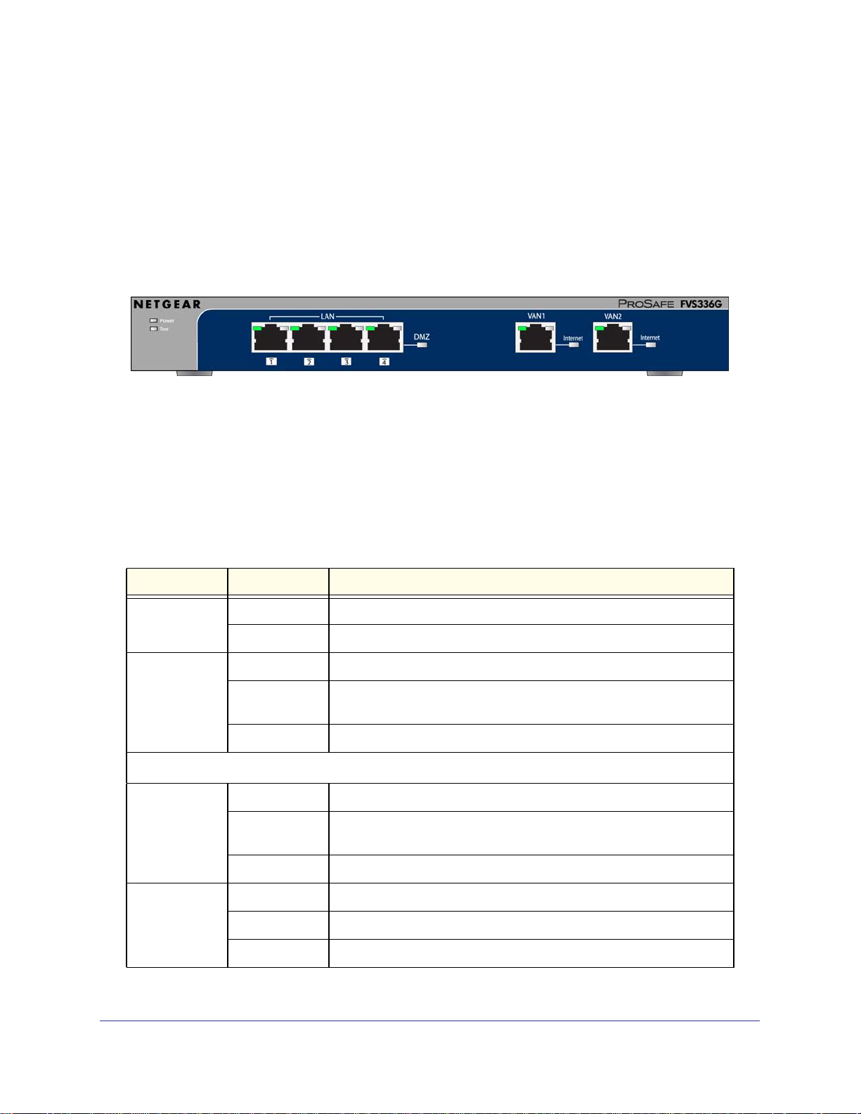
Front Panel Features
The front panel includes LAN Ethernet ports, WAN Ethernet ports, and four groups of status
indicator LEDs, including Power and Test, LAN, WAN1, and WAN2:
Figure 1-1 Front Panel
• LAN Ethernet ports: Four switched N-way automatic speed negotiating, Auto MDI/MDIX,
Gigabit Ethernet ports with RJ-45 connectors.
• WAN Ethernet ports: Two independent N-way automatic speed negotiating, Auto
MDI/MDIX, Gigabit Ethernet ports with RJ-45 connectors.
The function of each LED is described in the following table:
Table 1-1. LED Descriptions
Object Activity Description
Power
Test
On (Green) Power is supplied to the FVS336Gv2.
Off Power is not supplied to the FVS336Gv2.
On (Amber) Test mode: The system is initializing or the initialization has failed.
Blinking
(Amber)
Off The system has booted successfully.
Writing to Flash memory (during upgrading or resetting to defaults).
WAN Ports
ACTIVE
SPEED
On (Green)
On (Amber)
Off
On (Green)
On (Amber)
Off
The WAN port has a valid Internet connection.
The Internet connection is down or not being used because the WAN
port is in standby for failover.
The WAN port is either not enabled or has no link.
The WAN port is operating at 1,000 Mbps.
The WAN port is operating at 100 Mbps.
The WAN port is operating at 10 Mbps.
Chapter 1: Introduction | 11
Page 12
ProSafe Dual WAN Gigabit Firewall with SSL & IPsec VPN FVS336Gv2 Reference Manual
Table 1-1. LED Descriptions (Continued)
Object Activity Description
LINK/ACT
(Link and
Activity)
On (Green)
Blinking (Green)
Off
The WAN port has detected a link with a connected Ethernet device.
Data is being transmitted or received by the WAN port.
The WAN port has no link.
LAN Ports
SPEED
LINK/ACT
(Link and
Activity)
On (Green)
On (Amber)
Off
On (Green)
Blinking (Green)
Off
The LAN port is operating at 1,000 Mbps.
The LAN port is operating at 100 Mbps.
The LAN port is operating at 10 Mbps.
The LAN port has detected a link with a connected Ethernet device.
Data is being transmitted or received by the LAN port.
The LAN port has no link.
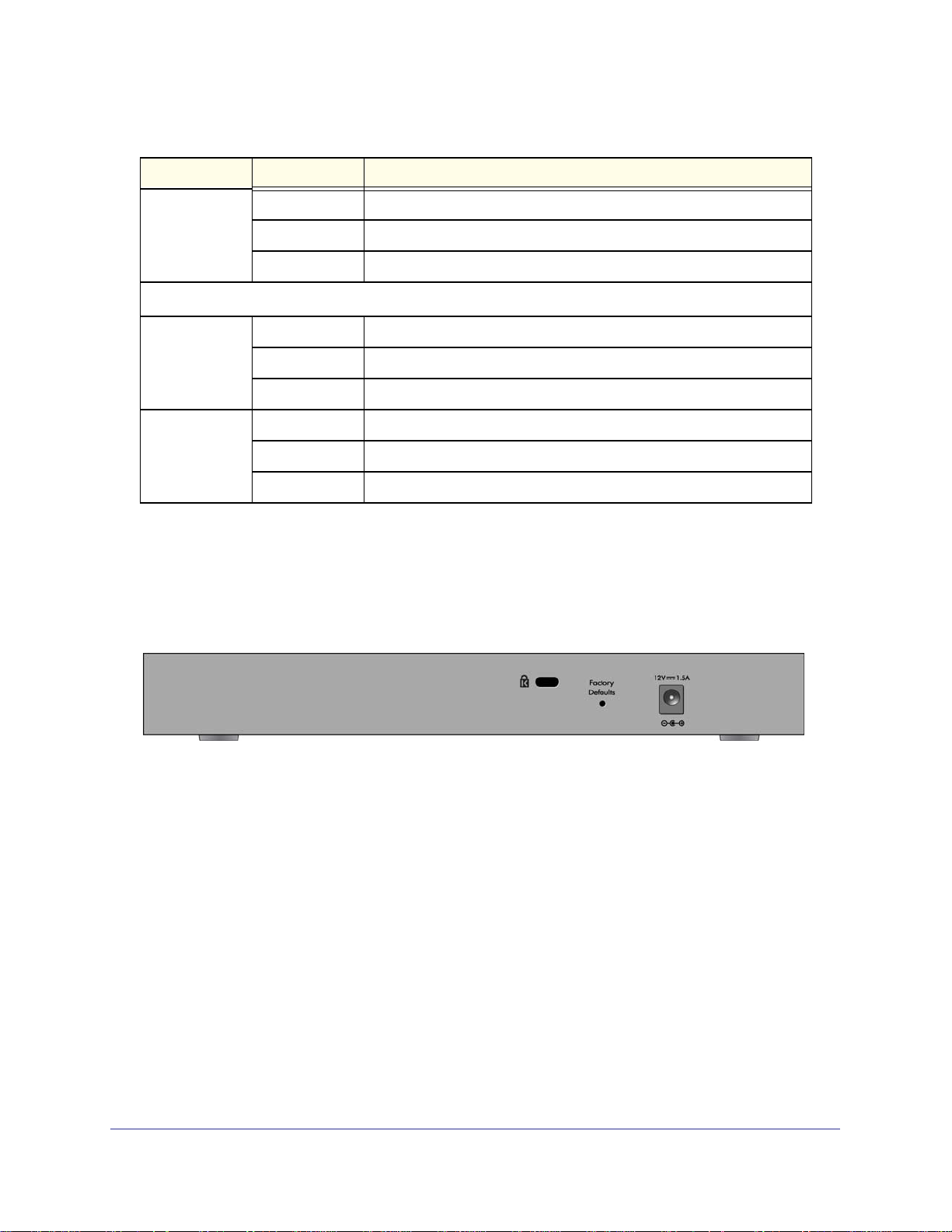
Rear Panel Features
The rear panel of the FVS336Gv2 includes Gigabit Ethernet LAN and WAN connections, a
cable lock receptacle, power and reset switches, and an AC power connection.
Figure 1-2 Rear Panel
Viewed from left to right, the rear panel contains the following elements:
• Cable security lock receptacle.
• Factory Defaults button: Using a sharp object, press and hold this button for about ten
seconds until the front panel TEST light flashes to reset the FVS336Gv2 to factory default
settings. All configuration settings will be lost and the default password will be restored.
• AC power receptacle: Universal AC input (100-240 VAC, 50-60 Hz).
Default IP Address, Login Name, and Password Location
Check the label on the bottom of the network storage’s enclosure if you need a reminder of
12 | Chapter 1: Introduction
Page 13
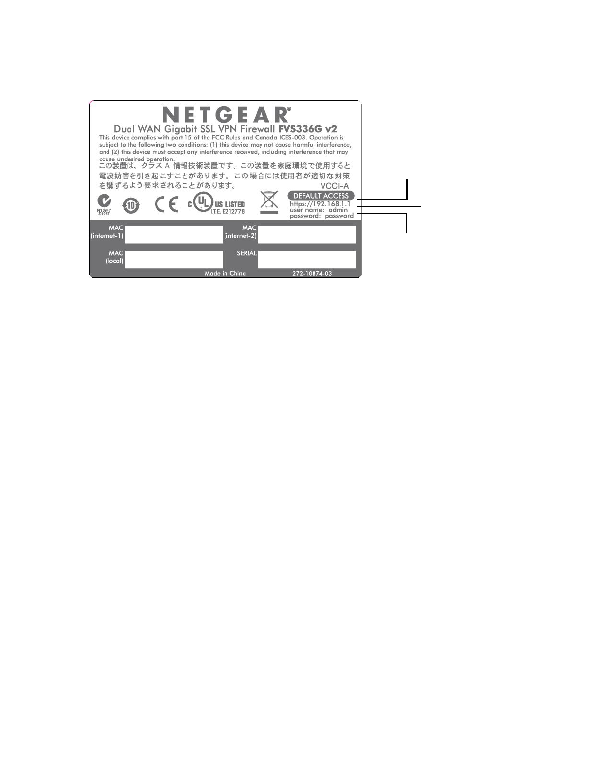
ProSafe Dual WAN Gigabit Firewall with SSL & IPsec VPN FVS336Gv2 Reference Manual
the following factory default information:
IP address
User name
Password
Figure 1-3 Product Lable
Qualified Web Browsers
To configure the network storage, you must use a Web browser such as Microsoft Internet
Explorer 6 or higher, Mozilla Firefox 3 or higher, or Apple Safari 3 or higher with JavaScript,
cookies, and you must have SSL enabled.
Although these Web browsers are qualified for use with the network storage’s Web
Management Interface for configuring the network storage, SSL VPN users should choose a
browser that supports JavaScript, Java, cookies, SSL, and ActiveX to take advantage of the
full suite of applications. Note that Java is only required for the SSL VPN portal, not the Web
Management Interface.
Chapter 1: Introduction | 13
Page 14

Connecting the VPN Firewall to the Internet
The initial Internet configuration of the VPN firewall, is described in this chapter. This chapter
contains the following sections:
• Understanding the Connection Steps” on this page.
• “Logging into the VPN Firewall” on page 15.
• “Navigating the Menus” on page 16.
• “Configuring the Internet Connections” on page 17.
• “Configuring the WAN Mode (Required for Dual WAN)” on page 22.
• “Configuring Dynamic DNS (Optional)” on page 26.
• “Configuring the Advanced WAN Options (Optional)” on page 28.
2
Understanding the Connection Steps
Typically, six steps are required to complete the basic Internet connection of your VPN
firewall.
1. Connect the network storage physically to your network. Connect the cables and
restart your network according to the instructions in the installation guide. See the
Installation Guide, FVS336G ProSafe Dual WAN Gigabit Firewall with SSL & IPsec VPN
for complete steps. A PDF of the Installation Guide is on the NETGEAR website at:
http://kbserver.netgear.com.
2. Log in to the VPN Firewall. After logging in, you are ready to set up and configure your
VPN firewall. You can also change your password and enable remote management at
this time. See “Logging into the VPN Firewall” on page 15.
3. Configure the Internet connections to your ISP(s). During this phase, you will
connect to your ISPs. See “Configuring the Internet Connections” on page 17.
4. Configure the WAN mode (required for dual WAN operation). Select either dedicated
(single WAN) mode, auto-rollover mode, or load balancing mode. For load balancing,
you can also select any necessary protocol bindings. See “Configuring the WAN Mode
(Required for Dual WAN)” on page 22.
Chapter 2: Connecting the VPN Firewall to the Internet | 14
Page 15
ProSafe Dual WAN Gigabit Firewall with SSL & IPsec VPN FVS336Gv2 Reference Manual
5. Configure dynamic DNS on the WAN ports (optional). Configure your fully qualified
domain names during this phase (if required). See “Configuring Dynamic DNS
(Optional)” on page 26.
6. Configure the WAN options (optional). Optionally, you can enable each WAN port to
respond to a ping, and you can change the factory default MTU size and port speed.
However, these are advanced features and changing them is not usually required. See
“Configuring the Advanced WAN Options (Optional)” on page 28.
Each of these tasks is detailed separately in this chapter. The configuration of firewall and
VPN features is described in later chapters.
Logging into the VPN Firewall
To connect to the VPN firewall, your computer needs to be configured to obtain an IP address
automatically from the VPN firewall by DHCP. For instructions on how to configure your
computer for DHCP, refer to the link to the online document Preparing Your Network in
Appendix D.
To connect and log in to the VPN firewall:
1. Start any of the qualified browsers, as detailed in “Qualified Web Browsers” on page 13.
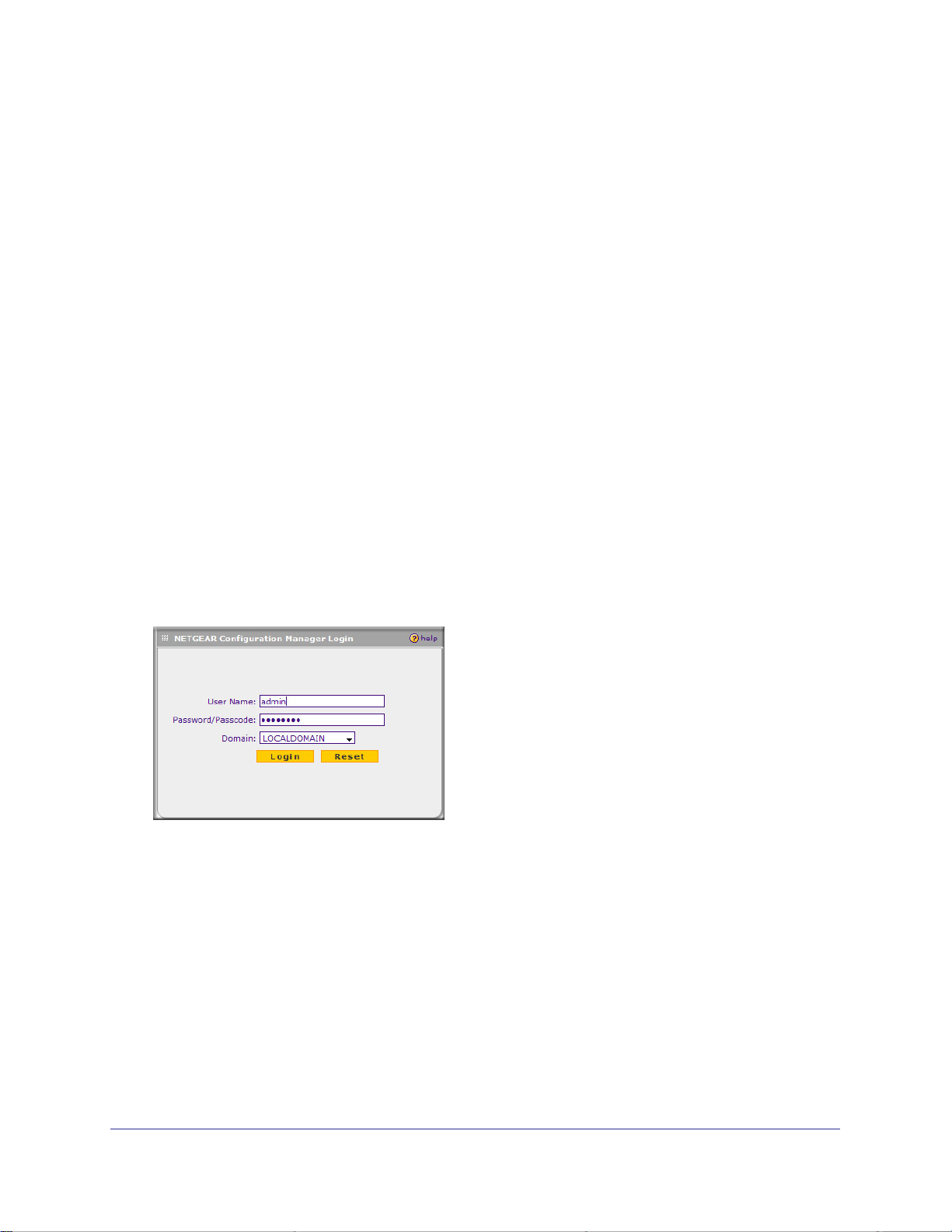
2. Enter https://192.168.1.1 in the address field. The Manager login features appear in the
browser.
3. In the User Name field, type admin
4. In the Password field, type password
Note that both entries are in lower case letters.
Chapter 2: Connecting the VPN Firewall to the Internet | 15
Page 16
ProSafe Dual WAN Gigabit Firewall with SSL & IPsec VPN FVS336Gv2 Reference Manual
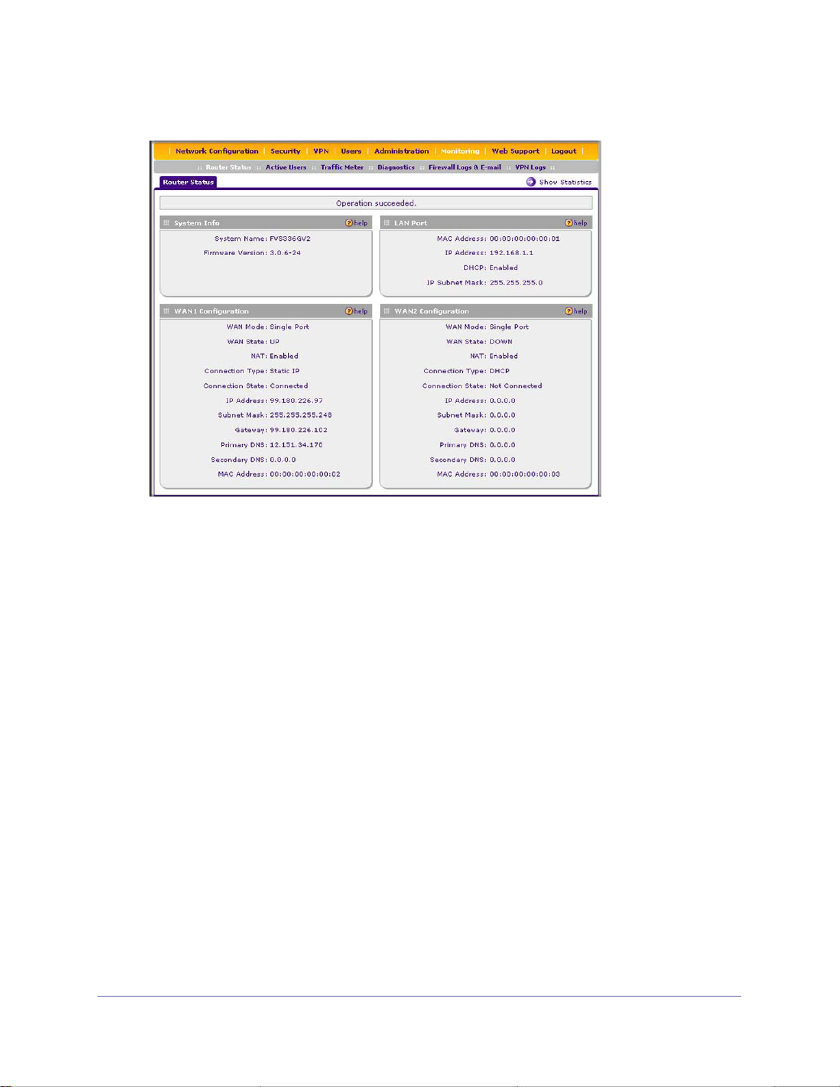
5. Click Login. The Web Configuration Manager screen appears, displaying Router Status:
Navigating the Menus
The Web Configuration Manager menus are organized in a layered structure of main
categories and submenus:
• Main menu. The horizontal orange bar near the top of the page is the main menu,
containing the primary configuration categories. Clicking on a primary category changes
the contents of the submenu bar.
• Submenu. The horizontal grey bar immediately below the main menu is the submenu,
containing subcategories of the currently selected primary category.
• Tab. Immediately below the submenu bar, at the top of the menu active window, are one
or more tabs, further subdividing the currently selected subcategory if necessary.
• Option arrow. To the right of the tabs on some menus are one or more blue dots with an
arrow in the center. Clicking an option arrow brings up either a popup window or an
advanced option menu.
You can now proceed to the first configuration task, configuring the VPN firewall’s Internet
connections.
16 | Chapter 2: Connecting the VPN Firewall to the Internet
Page 17
ProSafe Dual WAN Gigabit Firewall with SSL & IPsec VPN FVS336Gv2 Reference Manual
Configuring the Internet Connections
To set up your VPN firewall for secure Internet connections, you configure WAN port 1 and
WAN port 2. The Web Configuration Manager offers two connection configuration options:
• Automatic detection and configuration of the network connection.
• Manual configuration of the network connection.
Each option is detailed in the sections following.
Automatically Detecting and Connecting
To automatically configure the WAN ports for connection to the Internet:
1. Select Network Configuration > WAN Settings from the menu. The WAN Settings tabs
appear, with the WAN1 ISP Settings screen in view.
2. Click Auto Detect at the bottom of the page. Auto Detect will probe the WAN port for a
range of connection methods and suggest one that your ISP appears to support.
Chapter 2: Connecting the VPN Firewall to the Internet | 17
Page 18
ProSafe Dual WAN Gigabit Firewall with SSL & IPsec VPN FVS336Gv2 Reference Manual
Note: If you click Auto Detect while the WAN port already has a
connection, you might lose the connection because the VPN firewall
will enter its detection mode.
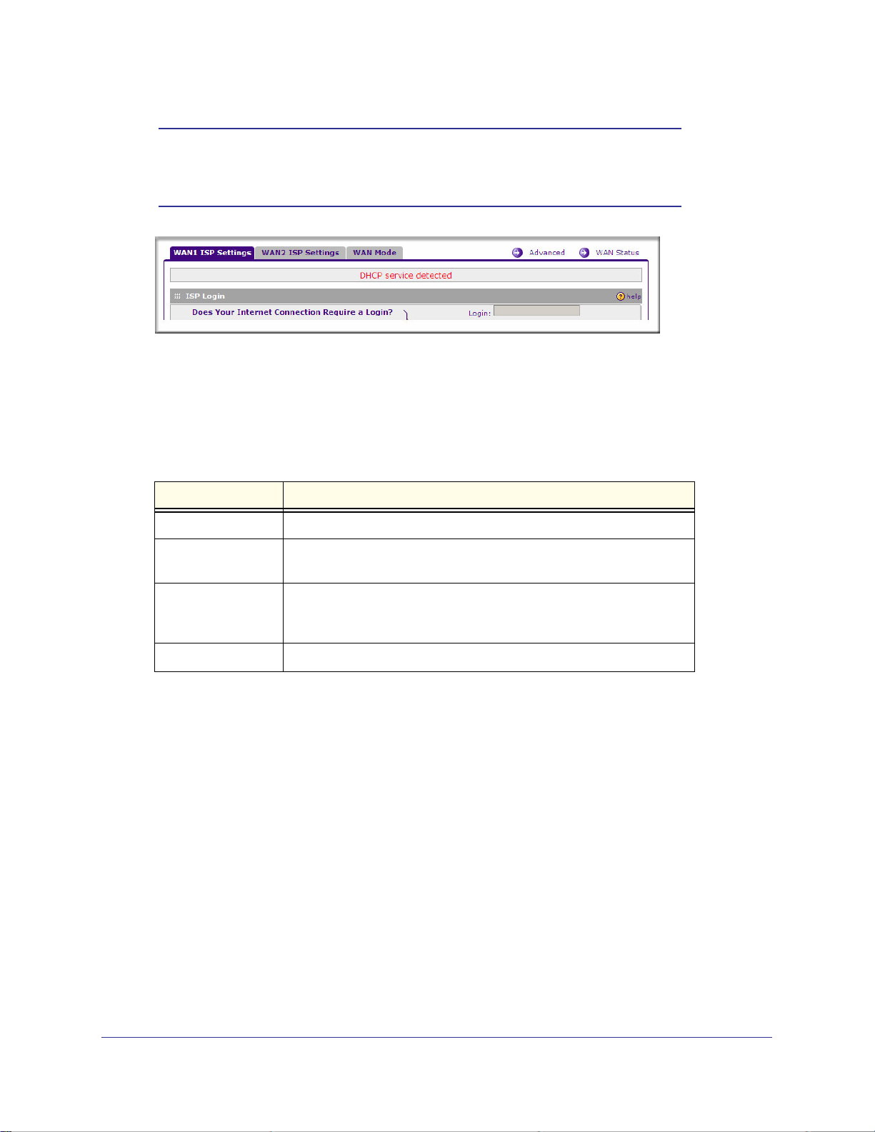
a. If Auto Detect is successful, a status bar at the top of the screen will display the
results.
b. If Auto Detect senses a connection method that requires input from you, it will
prompt you for the information. All methods with their required settings are detailed
in the following table.
Table 2-2.
Connection Method Data Required
DHCP (Dynamic IP) No data is required.
PPPoE Login (Username, Password);
Account Name, Domain Name (sometimes required).
PPTP Login (Username, Password),
Local IP address, and PPTP Server IP address;
Account Name (sometimes required).
Fixed (Static) IP Static IP address, Subnet, and Gateway IP; DNS Server IP addresses.
c. If Auto Detect does not find a connection, you will be prompted to (1) check the
physical connection between your VPN firewall and the cable or DSL line, or to (2)
check your VPN firewall’s MAC address (For more information, see “Configuring the
WAN Mode (Required for Dual WAN)” on page 22 and “Troubleshooting the ISP
Connection” on page 165.
3. To verify the connection, click the WAN
Status option arrow at the top right of the
screen. A popup window appears, displaying
the connection status of WAN port 1.
18 | Chapter 2: Connecting the VPN Firewall to the Internet
Page 19

ProSafe Dual WAN Gigabit Firewall with SSL & IPsec VPN FVS336Gv2 Reference Manual
The WAN Status window should show a valid IP address and gateway. If the
configuration was not successful, go to “Manually Configuring the Internet Connection”
on page 19 following this section, or see “Troubleshooting the ISP Connection” on
page 165.
Note: If the configuration process was successful, you are connected to
the Internet through WAN port 1. If you intend to use the dual WAN
capabilities of the VPN firewall, continue with the configuration
process for WAN port 2.
4. Click the WAN2 ISP Settings tab.
5. Repeat the previous steps to automatically detect and configure the WAN2 Internet
connection.
6. Open the WAN Status window and verify a successful connection
If your WAN ISP configuration was successful, you can go to “Configuring the WAN Mode
(Required for Dual WAN)” on page 22.
If one or both automatic WAN ISP configurations failed, you can attempt a manual
configuration as described in the following section, or see “Troubleshooting the ISP
Connection” on page 165.
Manually Configuring the Internet Connection
Unless your ISP automatically assigns your configuration automatically via DHCP, you will
need to obtain configuration parameters from your ISP in order to manually establish an
Internet connection. The necessary parameters for various connection types are listed in
Table 2-2 on page 18
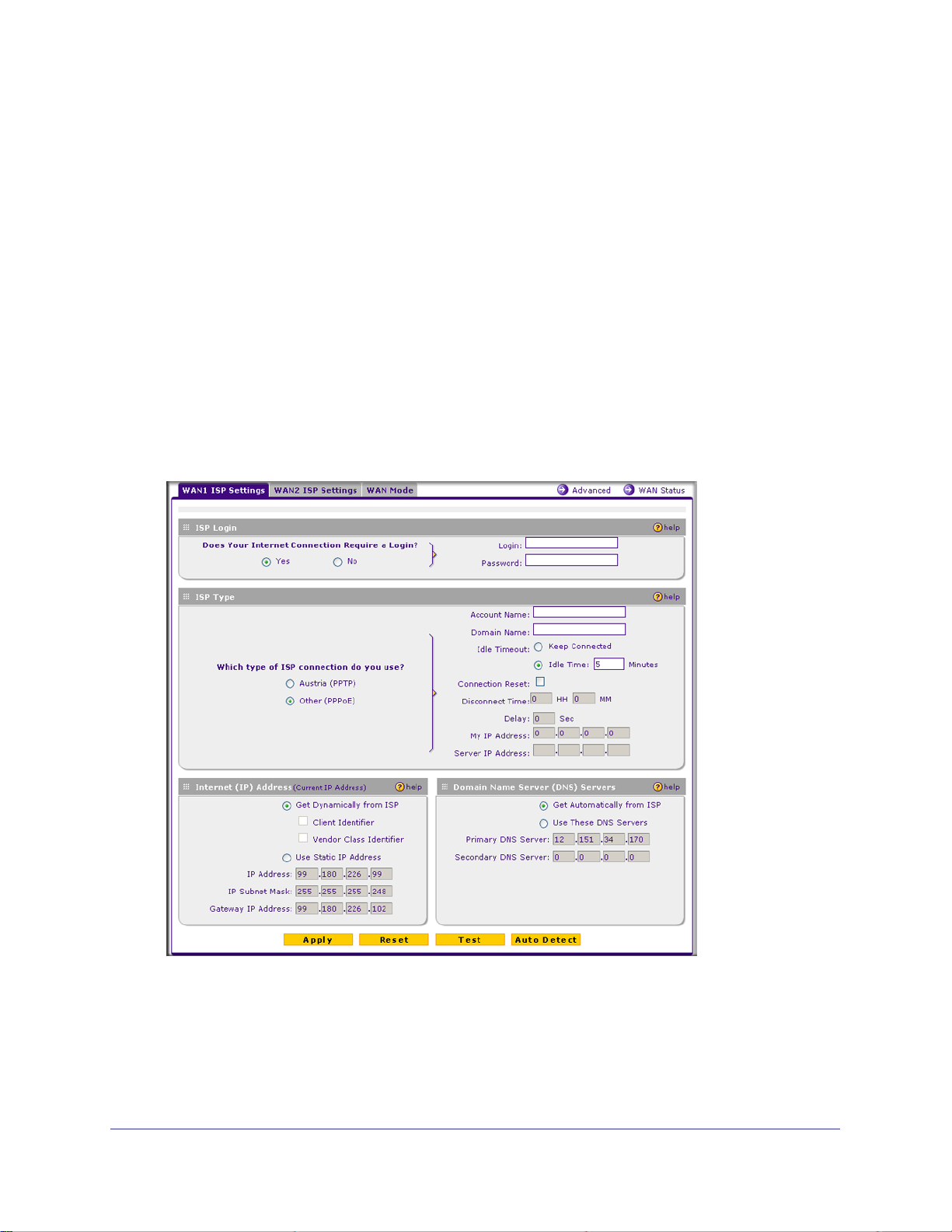
To manually configure the WAN1 ISP settings:
1. Select Network Configuration > WAN Settings from the menu. The WAN Settings
tabs appear, with the WAN1 ISP Settings screen in view.
2. In the ISP Login options, choose one of these options:
• If your ISP requires an initial login to establish an Internet connection, click Yes (this
is the default).
• If a login is not required, click No and ignore the Login and Password fields.
3. If you clicked Yes, enter the ISP-provided Login and Password information.
Chapter 2: Connecting the VPN Firewall to the Internet | 19
Page 20
ProSafe Dual WAN Gigabit Firewall with SSL & IPsec VPN FVS336Gv2 Reference Manual
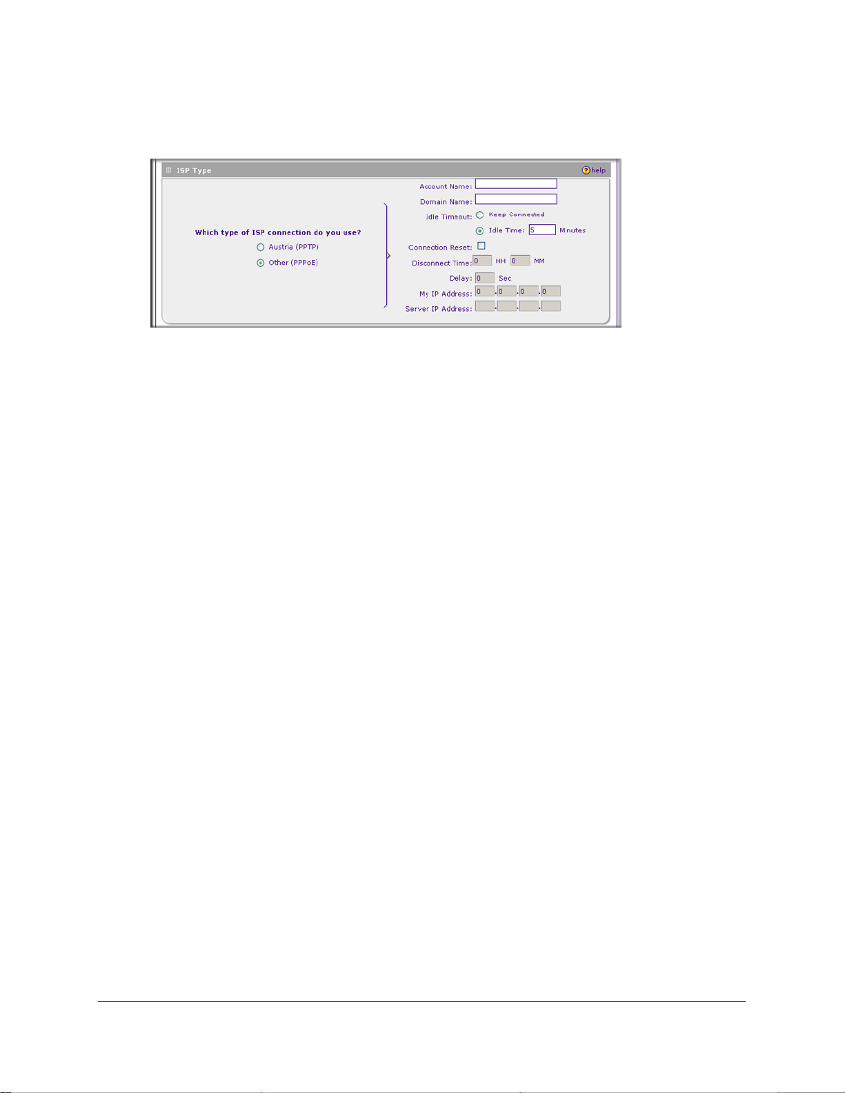
4. In the ISP Type options, select the type of ISP connection you use from the three listed
options. By default, “Other (PPPoE)” is selected, as shown below.
(If your connection is PPPoE or PPTP, your ISP will require an initial login.)
5. If you have installed login software such as WinPoET or Ethernet, then your connection
type is PPPoE. If your ISP uses PPPoE as a login protocol:
a. Select Other (PPPoE).
b. Configure the following fields:
• Account Name. Valid account name for the PPPoE connection.
• Domain Name. Name of your ISP’s domain or your domain name if your ISP has
assigned one. In most cases, you may leave this field blank.
• Idle Timeout. Select Keep Connected, to keep the connection always on. To
logout after the connection is idle for a period of time, click Idle Time and in the
timeout field enter the number of minutes to wait before disconnecting.
• Connection Reset. Select this checkbox to to specify a time when the PPPoE
WAN connection is reset, that is, the connection is disconnected momentarily and
then re-established. Enter the hour and minutes in the Disconnect Time fields to
specify when the connection should be disconnected. Enter the seconds in the
Delay field to specify the period after which the connection should be
re-established.
6. If your ISP is Austria Telecom or any other ISP that uses PPTP as a login protocol:
a. Select PPTP.
b. Configure the following fields:
• Account Name (also known as Host Name or System Name). Enter the valid
account name for the PPTP connection (usually your e-mail name as assigned by
your ISP). Some ISPs require entering your full e-mail address here.
• Domain Name. Your domain name or workgroup name assigned by your ISP, or
your ISPs domain name. You may leave this field blank.
• Idle Timeout. Check the Keep Connected radio button to keep the connection
always on. To logout after the connection is idle for a period of time, click Idle
Time and enter the number of minutes to wait before disconnecting in the timeout
field. This is useful if your ISP charges you based on the amount of time you have
logged in.
20 | Chapter 2: Connecting the VPN Firewall to the Internet
Page 21
ProSafe Dual WAN Gigabit Firewall with SSL & IPsec VPN FVS336Gv2 Reference Manual
• My IP Address. IP address assigned by the ISP to make the connection with the
ISP server.
• Server IP Address. IP address of the PPTP server.
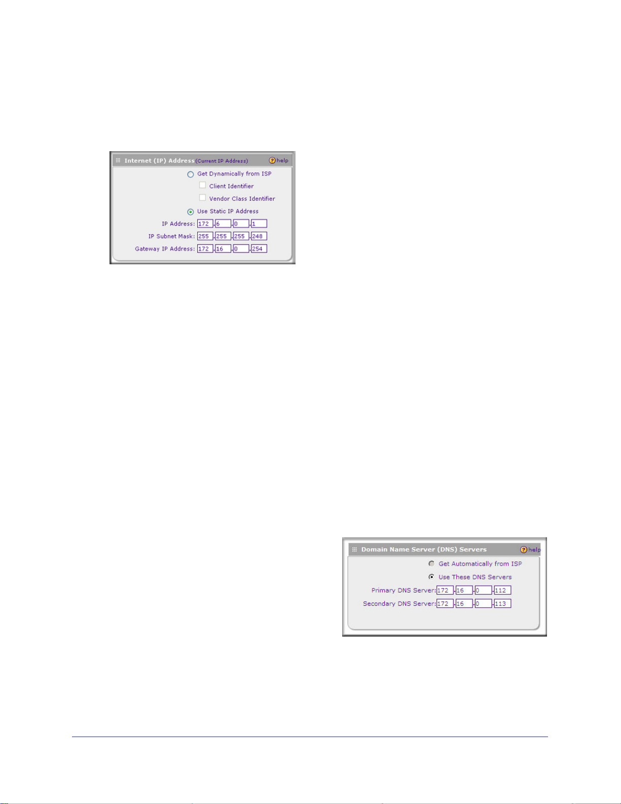
7. Review the Internet (IP) Address options.
8. If your ISP has not assigned a static IP address, click Get dynamically from ISP. The
ISP will automatically assign an IP address to the network storage using DHCP network
protocol. The IP address and subnet mask fields will be inactivated. As an option, you
can select the following checkboxes:
• Client Identifier. Select this checkbox if your ISP requires the Client Identifier
information to assign an IP address using DHCP.
• Vendor Class Identifier. Select this checkbox if your ISP requires the Vendor Class
Identifier information to assign an IP address using DHCP.
The ISP will automatically assign an IP address to the VPN firewall using DHCP network
protocol.
9. If your ISP has assigned a fixed (static) IP address, select Use Static IP Address, and
configure the following fields:
• IP Address. Enter the Static IP address assigned to you, that identifies the VPN
firewall to your ISP.
• Subnet Mask. Enter the mask provided by the ISP or your network administrator.
• Gateway IP Address. Enter the IP address of the ISP’s gateway, provided by the ISP
or your network administrator.
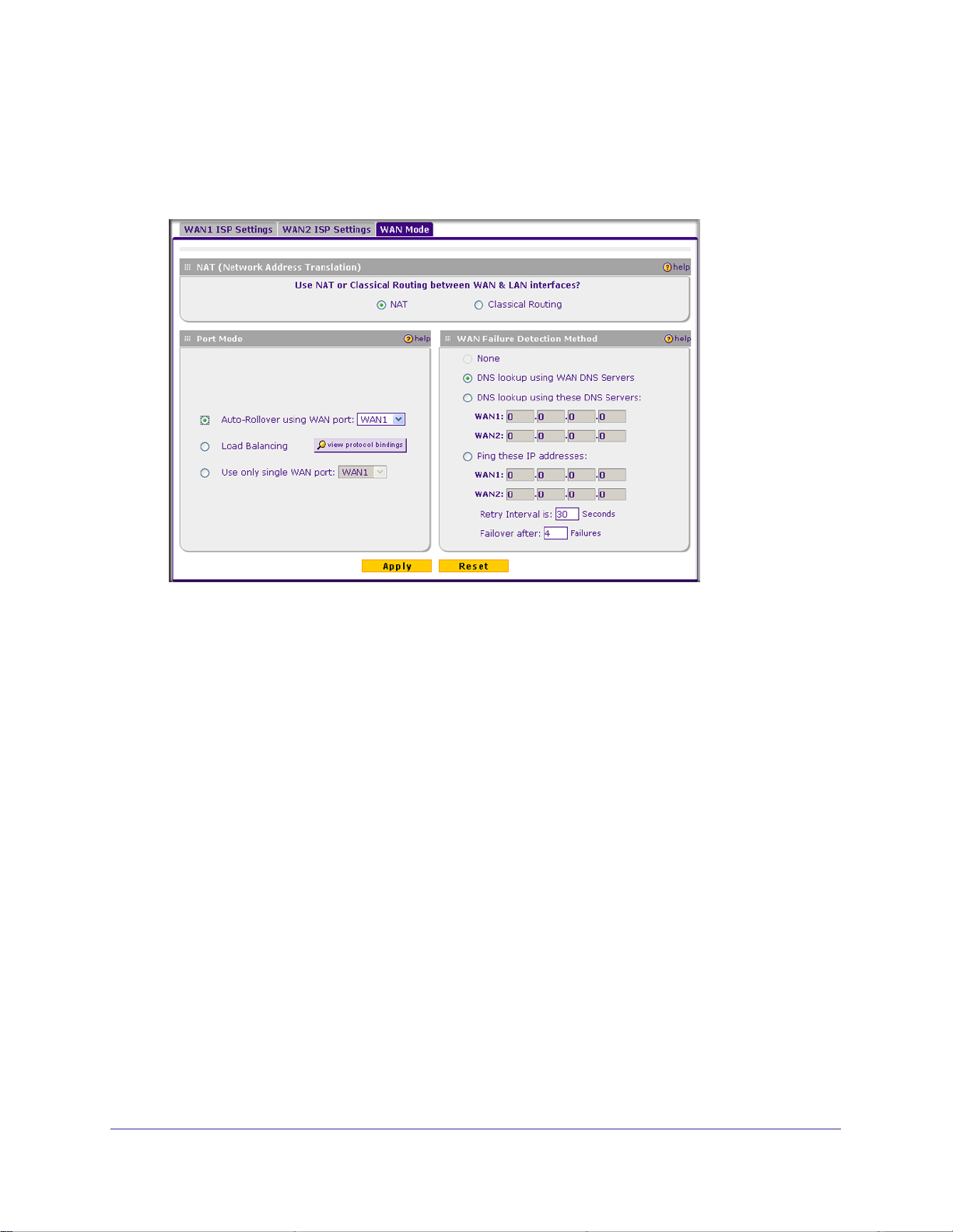
10. Review the Domain Name Server (DNS)
server options.
• If your ISP has not assigned any DNS
addresses, click Get dynamically from
ISP.
• If your ISP (or your IT department) has
assigned DNS addresses, click Use
these DNS Servers and enter the DNS
server IP addresses provided to you in the fields.
11. Click Apply to save any changes to the WAN1 ISP Settings. (Or click Reset to discard
any changes and revert to the previous settings.)
12. Click Test to evaluate your entries.
Chapter 2: Connecting the VPN Firewall to the Internet | 21
Page 22

ProSafe Dual WAN Gigabit Firewall with SSL & IPsec VPN FVS336Gv2 Reference Manual
The VPN firewall will attempt to connect to the NETGEAR website. If a successful
connection is made, NETGEAR’s website appears.
13. If you intend to use a dual WAN mode, click the WAN2 ISP Settings tab and configure
the WAN2 ISP settings using the same steps as WAN1.
Configuring the WAN Mode (Required for Dual WAN)
The dual WAN ports of the ProSafe Dual WAN Gigabit Firewall with SSL & IPsec VPN can be
configured on a mutually exclusive basis for either auto-rollover (for increased system
reliability) or load balancing (for maximum bandwidth efficiency), or one port can be disabled.
• Auto-Rollover Mode. The selected WAN interface is made primary and the other is the
rollover link. As long as the primary link is up, all traffic is sent over the primary link. Once
the primary WAN interface goes down, the rollover link is brought up to send the traffic.
Traffic will automatically roll back to the original primary link once the original primary link
is back up and running again. If you want to use a redundant ISP link for backup
purposes, select the WAN port that will act as the primary link for this mode. Ensure that
the backup WAN port has also been configured and that you configure in the WAN Failure
Detection Method section of the WAN Mode screen to support Auto-Rollover.
• Load Balancing Mode. The VPN firewall distributes the outbound traffic equally among
the WAN interfaces that are functional.
Note: Scenarios could arise when load balancing needs to be bypassed
for certain traffic or applications. If certain traffic needs to travel on a
specific WAN interface, configure protocol binding rules for that
WAN interface. The rule should match the desired traffic.
• Single WAN Port Mode. The selected WAN interface is made primary and the other is
disabled.
Whichever WAN mode you choose, you must also choose either NAT or classical routing, as
explained in the following sections.
Network Address Translation
Network Address Translation (NAT) allows all PCs on your LAN to share a single public
Internet IP address. From the Internet, there is only a single device (the VPN firewall) and a
single IP address. PCs on your LAN can use any private IP address range, and these IP
addresses are not visible from the Internet.
• The VPN firewall uses NAT to select the correct PC (on your LAN) to receive any
incoming data.
22 | Chapter 2: Connecting the VPN Firewall to the Internet
Page 23

ProSafe Dual WAN Gigabit Firewall with SSL & IPsec VPN FVS336Gv2 Reference Manual
• If you only have a single public Internet IP address, you MUST use NAT. (the default
setting).
• If your ISP has provided you with multiple public IP addresses, you can use one address
as the primary shared address for Internet access by your PCs, and you can map
incoming traffic on the other public IP addresses to specific PCs on your LAN. This
one-to-one inbound mapping is configured using an inbound firewall rule.
Classical Routing
In classical routing mode, the VPN firewall performs routing, but without NAT. To gain Internet
access, each PC on your LAN must have a valid static Internet IP address.
If your ISP has allocated a number of static IP addresses to you, and you have assigned one
of these addresses to each PC, you can choose classical routing. Or, you can use classical
routing for routing private IP addresses within a campus environment. To learn the status of
the WAN ports, you can view the Router Status screen (see <pdf>“Viewing VPN Firewall
Configuration and System Status” on page 9-154) or look at the LEDs on the front panel (see
“Rear Panel Features” on page 12).
Configuring Auto-Rollover Mode
To use a redundant ISP link for backup purposes, ensure that the backup WAN port has
already been configured. Then select the WAN port that will act as the primary link for this
mode and configure the WAN Failure Detection Method to support Auto-Rollover.
When the VPN firewall is configured in Auto-Rollover mode, it uses the selected WAN Failure
Detection Method to check the connection of the primary link at regular intervals to detect its
routing status. Link failure is detected in one of the following ways:
• By sending DNS queries to a DNS server, or
• By sending a Ping request to an IP address, or
• None (no failure detection is performed).
From each WAN interface, DNS queries or Ping requests are sent to the specified IP
address. If replies are not received, after a specified number of retries, the corresponding
WAN interface is considered down.
Chapter 2: Connecting the VPN Firewall to the Internet | 23
Page 24
ProSafe Dual WAN Gigabit Firewall with SSL & IPsec VPN FVS336Gv2 Reference Manual
To configure the dual WAN ports for Auto-Rollover:
1. Select Network Configuration > WAN Settings from the menu, and click the WAN Mode
tab. The WAN Mode screen is displayed
2. In the Port Mode section, select Auto-Rollover Using WAN port.
3. From the drop-down list, choose which WAN port will act as the primary link for this
mode.
4. In the WAN Failure Detection Method section, select one of the following detection
failure methods:
• DNS lookup using ISP DNS Servers. DNS queries are sent to the DNS server
configured on the WAN ISP screens (see <pdf>“Configuring the Internet
Connections” on page 2-17).
• DNS lookup using this DNS Server. Enter a public DNS server. DNS queries are
sent to this server through the WAN interface being monitored.
• Ping to this IP addresses. Enter a public IP address that will not reject the Ping
request and will not consider Ping traffic to be abusive. Queries are sent to this server
through the WAN interface being monitored.
5. Enter a Retry Interval in seconds. The DNS query or Ping is sent periodically after
every test period. The default test period is 30 seconds.
6. Enter the Failover after count. The WAN interface is considered down after the
configured number of queries have failed to elicit a reply. The rollover link is brought up
after this. The Failover default is 4 failures.
The default time to roll over after the primary WAN interface fails is 2 minutes (a
30-second minimum test period for a minimum of 4 tests).
7. Click Apply to save your settings.
24 | Chapter 2: Connecting the VPN Firewall to the Internet
Page 25
ProSafe Dual WAN Gigabit Firewall with SSL & IPsec VPN FVS336Gv2 Reference Manual
Once a rollover occurs, an alert will be generated (see <pdf>“E-Mail Notifications of Event
Logs and Alerts” on page 4-68). When the VPN firewall detects that the failed primary WAN
interface has been restored, it will automatically rollover again to the primary WAN interface.
Alternatively, you can manually force traffic back on the original primary WAN interface by
reapplying the Auto-Rollover settings on the WAN Mode screen.
Configuring Load Balancing
To use multiple ISP links simultaneously, select Load Balancing. In Load Balancing mode,
either WAN port will carry any outbound protocol unless protocol binding is configured. When
a protocol is bound to a particular WAN port, all outgoing traffic of that protocol will be
directed to the bound WAN port. For example, if the HTTPS protocol is bound to WAN1 and
the FTP protocol is bound to WAN2, then the VPN firewall will automatically route all
outbound HTTPS traffic from the computers on the LAN through the WAN1 port. All outbound
FTP traffic will be routed through the WAN2 port.
Protocol binding
Protocol binding addresses two issues:
• Segregation of traffic between links that are not of the same speed.
High volume traffic can be routed through the WAN port connected to a high speed link
and low volume traffic can be routed through the WAN port connected to the low speed
link.
• Continuity of source IP address for secure connections.
Some services, particularly HTTPS, will cease responding when a client’s source IP
address changes shortly after a session has been established.
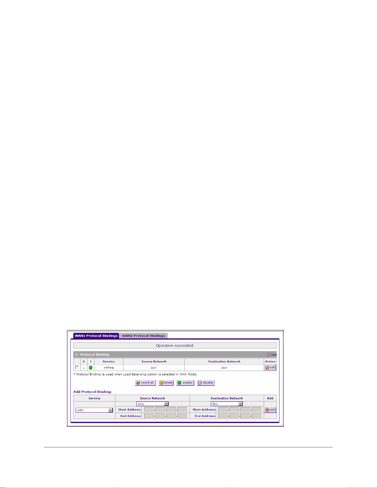
To configure the dual WAN ports for load balancing with protocol binding:
1. Select Network >WAN Settings from the menu, and click the WAN Mode tab.
2. In the Port Mode section, select Load Balancing.
3. Click view protocol bindings (if required). The WAN1 Protocol Bindings screen is
displayed.
Chapter 2: Connecting the VPN Firewall to the Internet | 25
Page 26

ProSafe Dual WAN Gigabit Firewall with SSL & IPsec VPN FVS336Gv2 Reference Manual
Enter the following data in the Add Protocol Binding section on screen:
a. Service. From the drop-down list, choose the desired service or application to be
covered by this rule. If the desired service or application does not appear in the list,
you must define it using the Services screen (see “Adding Customized Services” on
page 57).
b. Source Network. These settings determine which computers on your network are
affected by this rule. Select the desired options:
• Any. All PCs and devices on your LAN.
• Single address. Enter the required address and the rule will be applied to that
particular PC.
• Address range. If this option is selected, you must enter the start and finish fields.
• Group 1-Group 8. If this option is selected, the devices assigned to this group will
be affected. (You may also assign a customized name to the group. See Edit
Group Names on the Groups and Hosts screen in the LAN Groups submenu.)
c. Destination Network. These settings determine which Internet locations are
covered by the rule, based on their IP address. Select the desired option:
• Any. All Internet IP address are covered by this rule.
• Single address. Enter the required address in the start field.
• Address range. If this option is selected, you must enter the start and finish fields.
4. Click Add to save this rule.
The new Protocol Binding Rule will be enabled and added to the Protocol Binding Table
for the WAN1 port.
5. Open the WAN2 Protocol Bindings tab and repeat the previous steps to set protocol
bindings for the WAN2 port.
Configuring Dynamic DNS (Optional)
Dynamic DNS (DDNS) is an Internet service that allows routers with varying public IP
addresses to be located using Internet domain names. To use DDNS, you must setup an
account with a DDNS provider such as DynDNS.org, TZO.com, Oray.net, or 3322.org. (Links
to DynDNS, TZO, Oray, and 3322 are provided for your convenience on the Dynamic DNS
Configuration screen.) The VPN firewall firmware includes software that notifies dynamic
DNS servers of changes in the WAN IP address, so that the services running on this network
can be accessed by others on the Internet.
If your network has a permanently assigned IP address, you can register a domain name and
have that name linked with your IP address by public Domain Name Servers (DNS).
However, if your Internet account uses a dynamically assigned IP address, you will not know
in advance what your IP address will be, and the address can change frequently—hence, the
need for a commercial DDNS service, which allows you to register an extension to its
domain, and restores DNS requests for the resulting FQDN to your frequently-changing IP
address.
26 | Chapter 2: Connecting the VPN Firewall to the Internet
Page 27
ProSafe Dual WAN Gigabit Firewall with SSL & IPsec VPN FVS336Gv2 Reference Manual
After you have configured your account information in the network storage, whenever your
ISP-assigned IP address changes, your network storage will automatically contact your
DDNS service provider, log in to your account, and register your new IP address.
You may need to use a fully qualified domain name (FQDN):
• For auto-rollover mode, you will need a FQDN to implement features such as exposed
hosts and virtual private networks regardless of whether you have a fixed or dynamic IP
address.
• For load balancing mode, you may still need a FQDN either for convenience or if you
have a dynamic IP address.
Note: If your ISP assigns a private WAN IP address such as 192.168.x.x
or 10.x.x.x, the dynamic DNS service will not work because private
addresses will not be routed on the Internet.
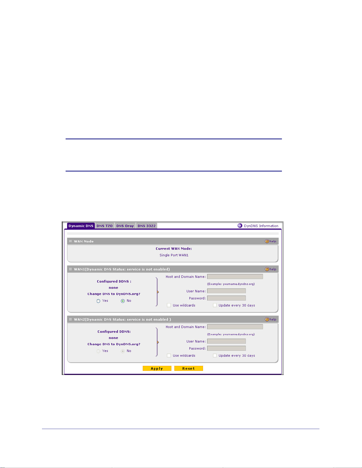
To configure dynamic DNS:
1. Select Network Configuration > Dynamic DNS from the menu and click the Dynamic
DNS Configuration tab. The Dynamic DNS Configuration screen is displayed.
The Current WAN Mode section reports the currently configured WAN mode. (For
example, Single Port WAN1, Load Balancing or Auto Rollover.) Only those options that
match the configured WAN Mode will be accessible.
2. Select the tab for the DDNS service provider you will use.
Chapter 2: Connecting the VPN Firewall to the Internet | 27
Page 28
ProSafe Dual WAN Gigabit Firewall with SSL & IPsec VPN FVS336Gv2 Reference Manual
3. Click the information or registration link in the upper right corner for registration
information.
4. Access the website of the DDNS service provider and register for an account (for
example, for dyndns.org, go to http://www.dyndns.org).
5. For each WAN port, click the Yes radio button for Change DNS to <your desired DDNS
service> and configure the active fields:
a. Enter the account information for the service you have chosen (for example, user
name, password, key, or domain).
b. If your DDNS provider allows the use of wild cards in resolving your URL, you may
select the Use wildcards checkbox to activate this feature. For example, the
wildcard feature will cause
address as
c. If your WAN IP address does not change often, you may need to force a periodic
update to the DDNS service to prevent your account from expiring. If it appears, you
can select the Update every 30 days checkbox to enable a periodic update.
yourhost.dyndns.org
*.yourhost.dyndns.org to be aliased to the same IP
6. Click Apply to save your configuration.
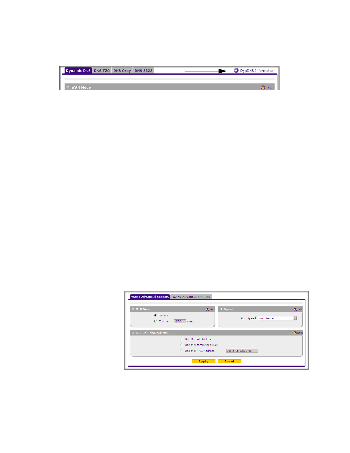
Configuring the Advanced WAN Options (Optional)
To configure the Advanced WAN options:
1. Select Network Configuration > WAN Settings from the menu. The WAN1 ISP Settings
screen is displayed.
2. Click the Advanced link to the right of the tabs.
The WAN1
Advanced Options
screen is displayed:
3. Edit the default
information you
want to change.
28 | Chapter 2: Connecting the VPN Firewall to the Internet
Page 29

ProSafe Dual WAN Gigabit Firewall with SSL & IPsec VPN FVS336Gv2 Reference Manual
a. MTU Size. The normal MTU (Maximum Transmit Unit) value for most Ethernet
networks is 1500 Bytes, or 1492 Bytes for PPPoE connections. For some ISPs, you
may need to reduce the MTU. This is rarely required, and should not be done unless
you are sure it is necessary for your ISP connection.
b. Port Speed. In most cases, your VPN firewall can automatically determine the
connection speed of the WAN port. If you cannot establish an Internet connection
and the WAN Link or Speed LED blinks continuously, you may need to manually
select the port speed. AutoSense is the default.
If you know that the Ethernet port on your broadband modem supports 100BaseT,
select 100BaseT Half_Duplex; otherwise, select 10BaseT Half_Duplex. Use the
half-duplex settings unless you are sure you need full duplex.
c. Router's MAC Address. Each computer or router on your network has a unique
32-bit local Ethernet address. This is also referred to as the computer's MAC (Media
Access Control) address. The default is Use default address. However, if your ISP
requires MAC authentication, then select either of these options:
• Use this Computer's MAC address to have the VPN firewall use the MAC address
of the computer you are now using, or
• Use This MAC Address to manually type in the MAC address that your ISP
expects.
The format for the MAC address is 01:23:45:67:89:AB (numbers 0-9 and either
uppercase or lowercase letters A-F). If you select Use This MAC Address and then
type in a MAC address, your entry will be overwritten.
4. Click Apply to save your changes.
Additional WAN Related Configuration
• If you want the ability to manage the network storage remotely, enable remote
management at this time (see “Enabling Remote Management Access” on page 139). If
you enable remote management, we strongly recommend that you change your
password (see “Changing Passwords and Administrator Settings” on page 137).
• At this point, you can set up the traffic meter for each WAN. See “Enabling the Traffic
Meter” on page 149.
Chapter 2: Connecting the VPN Firewall to the Internet | 29
Page 30

LAN Configuration
3
This chapter describes how to configure the advanced LAN features of your ProSafe Dual WAN
Gigabit Firewall with SSL & IPsec VPN FVS336Gv2.
This chapter contains the following sections
• Choosing the VPN Firewall DHCP Options” on this page.
• “Configuring the LAN Setup Options” on page 31.
• “Managing Groups and Hosts (LAN Groups)” on page 34.
• “Configuring Multi Home LAN IP Addresses” on page 38.
• “Configuring Static Routes” on page 39.
• “Configuring Routing Information Protocol (RIP)” on page 40.
Choosing the VPN Firewall DHCP Options
By default, the network storage will function as a DHCP (Dynamic Host Configuration
Protocol) server, allowing it to assign IP, DNS server, WINS Server, and default gateway
addresses to all computers connected to the network storage’s LAN. The assigned default
gateway address is the LAN address of the network storage. IP addresses will be assigned to
the attached PCs from a pool of addresses that you must specify. Each pool address is
tested before it is assigned to avoid duplicate addresses on the LAN.
For most applications, the default DHCP and TCP/IP settings of the VPN firewall are
satisfactory. See the link to the online document TCP/IP Networking Basics in Appendix D for
information about how to assign IP addresses for your network.
If another device on your network will be the DHCP server, or if you will manually configure
the network settings of all of your computers, clear the Enable DHCP server radio box by
selecting the Disable DHCP Server radio box. Otherwise, leave it checked.
Specify the pool of IP addresses to be assigned by setting the starting IP address and ending
IP address. These addresses should be part of the same IP address subnet as the network
storage’s LAN IP address. Using the default addressing scheme, you should define a range
Chapter 3: LAN Configuration | 30
Page 31

ProSafe Dual WAN Gigabit Firewall with SSL & IPsec VPN FVS336Gv2 Reference Manual
between 192.168.1.2 and 192.168.1.100, although you may wish to save part of the range for
devices with fixed addresses.
The network storage will deliver the following parameters to any LAN device that requests
DHCP:
• An IP address from the range you have defined.
• Subnet mask.
• Gateway IP address (the network storage’s LAN IP address).
• Primary DNS server (the network storage’s LAN IP address).
• WINS server (if you entered a WINS server address on the DHCP section of the LAN
Setup screen).
• Lease time (date obtained and duration of lease).
DHCP Relay options allow you to make the network storage a dhcp relay agent. The DHCP
Relay Agent makes it possible for DHCP broadcast messages to be sent over routers that do
not support forwarding of these types of messages. The DHCP Relay Agent is therefore the
routing protocol that enables DHCP clients to obtain IP addresses from a DHCP server on a
remote subnet, or which is not located on the local subnet. If you have no configured DHCP
Relay Agent, your clients would only be able to obtain IP addresses from the DHCP server
which is on the same subnet. To enable clients to obtain IP addresses from a DHCP server
on a remote subnet, you have to configure the DHCP Relay Agent on the subnet that
contains the remote clients, so that it can relay DHCP broadcast messages to your DHCP
server.
When the DNS Proxy option is enabled, the network storage will act as a proxy for all DNS
requests and communicate with the ISP’s DNS servers (as configured in the WAN settings
screen). All DHCP clients will receive the Primary/Secondary DNS IP along with the IP
address where the DNS Proxy is running, that is, the network storage’s LAN IP address.
When disabled, all DHCP clients will receive the DNS IP addresses of the ISP excluding the
DNS Proxy IP address. The feature is particularly useful in Auto Rollover mode. For example,
if the DNS servers for each connection are different, then a link failure may render the DNS
servers inaccessible. However, when the DNS proxy is enabled, then clients can make
requests to the network storage and the network storage, in turn, sends those requests to the
DNS servers of the active connection.
Configuring the LAN Setup Options
The LAN Setup screen allows configuration of LAN IP services such as DHCP and allows you to
configure a secondary or “multi-home” LAN IP setup in the LAN. The default values are suitable
for most users and situations. Disable the DNS Proxy if you are using a dual WAN configuration
with route diversity and failover. These are advanced settings most usually configured by a
network administrator.
Chapter 3: LAN Configuration | 31
Page 32

ProSafe Dual WAN Gigabit Firewall with SSL & IPsec VPN FVS336Gv2 Reference Manual
Note: If you enable the DNS Relay feature, you will not use the network
storage as a DHCP server but rather as a DHCP relay agent for a
DHCP server somewhere else on your network.
1. Go to Network Configuration > LAN Settings to display the LAN Setup screen.
2. In the LAN TCP/IP Setup section, configure the following settings:
• IP Address. The LAN address of your VPN firewall (factory default: 192.168.1.1).
Note: If you change the LAN IP address of the network storage while
connected through the browser, you will be disconnected. You must
then open a new connection to the new IP address and log in again.
For example, if you change the default IP address 192.168.1.1 to
10.0.0.1, you must now enter https://10.0.0.1 in your browser to
reconnect to the Web Configuration Manager.
• IP Subnet Mask. The subnet mask specifies the network number portion of an IP
address. Your VPN firewall will automatically calculate the subnet mask based on the
IP address that you assign. Unless you are implementing subnetting, use
255.255.255.0 as the subnet mask.
32 | Chapter 3: LAN Configuration
Page 33

ProSafe Dual WAN Gigabit Firewall with SSL & IPsec VPN FVS336Gv2 Reference Manual
3. In the DHCP section, select Disable DHCP Server, Enable DHCP Server, or DHCP
Relay.
By default, the VPN firewall will function as a DHCP server, providing TCP/IP
configuration settings for all computers connected to the VPN firewall's LAN. If another
device on your network will be the DHCP server, or if you will manually configure all
devices, click Disable DHCP Server. If the VPN firewall will function as a DHCP relay
agent, select DHCP Relay and enter the IP address of the DHCP relay gateway in the
Relay Gateway field.
If the DHCP server is enabled, enter the following parameters:
• Domain Name. (Optional) The DHCP will assign the entered domain to DHCP
clients.
• Starting IP Address. Specifies the first of the contiguous addresses in the IP address
pool. Any new DHCP client joining the LAN will be assigned an IP address between
this address and the Ending IP Address. The IP address 192.168.1.2 is the default
start address.
• Ending IP Address. Specifies the last of the contiguous addresses in the IP address
pool. The IP address 192.168.1.100 is the default ending address.
Note: The starting and ending DHCP addresses should be in the same
subnet as the LAN IP address of the VPN firewall (the IP address
configured in the LAN TCP/IP Setup section of the LAN Setup
screen).
• Primary DNS Server. (Optional) If an IP address is specified, the VPN firewall will
provide this address as the primary DNS server IP address. If no address is specified,
the VPN firewall will provide its own LAN IP address as the primary DNS server IP
address.
• Secondary DNS Server. (Optional) If an IP address is specified, the VPN firewall will
provide this address as the secondary DNS server IP address.
• WINS Server. (Optional) Specifies the IP address of a local Windows NetBIOS Server
if one is present in your network.
• Lease Time. This specifies the duration for which IP addresses will be leased to
clients.
If you will use a Lightweight Directory Access Protocol (LDAP) authentication server for
network-validated domain-based authentication, select Enable LDAP Information to
enable the DHCP server to provide LDAP server information. Enter the following
parameters:
• LDAP Server. Specifies the name or the IP address of the device that hosts the LDAP
server.
• Search Base. Specifies the distinguished name (dn) at which to start the search,
specified as a sequence of relative distinguished names (rdn), connected with
Chapter 3: LAN Configuration | 33
Page 34

ProSafe Dual WAN Gigabit Firewall with SSL & IPsec VPN FVS336Gv2 Reference Manual
commas and without any blank spaces. For most users, the search base is a variation
of the domain name. For example, if your domain is yourcompany.com, your search
base dn might be as follows: dc=yourcompany,dc=com.
• port. Specifies the port number that the LDAP server is using. Leave this field blank
for the default port.
4. In the Advanced Settings section, configure the following settings:
• Enable DNS Proxy. If the DNS proxy is enabled (which is the default setting), the
DHCP server will provide the VPN firewall’s LAN IP address as the DNS server for
address name resolution. If this box is unchecked, the DHCP server will provide the
ISP’s DNS server IP addresses. The VPN firewall will still service DNS requests sent
to its LAN IP address unless you disable DNS Proxy in the network storage settings
(see “Attack Checks” on page 54).
• Enable ARP Broadcast. If ARP broadcast is enabled (which is the default setting),
the Address Resolution Protocol (ARP) is broadcasted on the LAN so that IP
addresses can be mapped to physical addresses (that is, MAC addresses).
5. Click Apply to save your settings.
Note: Once you have completed the LAN setup, all outbound traffic is
allowed and all inbound traffic is discarded. To change these default
traffic rules, refer to Chapter 4,“Firewall Protection and Content
Filtering".
Managing Groups and Hosts (LAN Groups)
The Known PCs and Devices table on the LAN Groups screen contains a list of all known
PCs and network devices that are assigned dynamic IP addresses by the VPN firewall, or
have been discovered by other means. Collectively, these entries make up the LAN Groups
Database.
The LAN Groups Database is updated by these methods:
• DHCP Client Requests. By default, the DHCP server in this VPN firewall is enabled, and
will accept and respond to DHCP client requests from PCs and other network devices.
These requests also generate an entry in the LAN Groups Database. Because of this,
leaving the DHCP server feature (on the LAN screen) enabled is strongly recommended.
• Scanning the Network. The local network is scanned using ARP requests. The ARP
scan will detect active devices that are not DHCP clients. However, sometimes the name
of the PC or device cannot be accurately determined, and will appear in the database as
Unknown.
• Manual Entry. You can manually enter information about a network device.
34 | Chapter 3: LAN Configuration
Page 35

ProSafe Dual WAN Gigabit Firewall with SSL & IPsec VPN FVS336Gv2 Reference Manual
Some advantages of the LAN Groups Database are:
• Generally, you do not need to enter either IP address or MAC addresses. Instead, you
can just select the desired PC or device.
• No need to reserve an IP address for a PC in the DHCP server. All IP address
assignments made by the DHCP server will be maintained until the PC or device is
removed from the database, either by expiry (inactive for a long time) or by you.
• No need to use a fixed IP on PCs. Because the address allocated by the DHCP server
will never change, you don't need to assign a fixed IP to a PC to ensure it always has the
same IP address.
• MAC level control over PCs. The LAN Groups Database uses the MAC address to
identify each PC or device. So changing a PC’s IP address does not affect any
restrictions on that PC.
• Group and individual control over PCs.
- You can assign PCs to Groups and apply restrictions to each Group using the Firewall
Rules screen (see “Using Rules to Block or Allow Specific Kinds of Traffic” on
page 43).
- You can also select the Groups to be covered by the Block Sites feature (see
“Blocking Internet Sites (Content Filtering)” on page 62).
- If necessary, you can also create Firewall Rules to apply to a single PC (see
“Configuring Source MAC Filtering” on page 64). Because the MAC address is used
to identify each PC, users cannot avoid these restrictions by changing their IP
address.
• A computer is identified by its MAC address—not its IP address. Hence, changing a
computer’s IP address does not affect any restrictions applied to that PC.
Viewing the LAN Groups Database
To view the LAN Groups Database, follow these steps:
1. Select Network Configuration > LAN Settings from the menu. The LAN Setup screen is
displayed.
2. Click the LAN Groups tab. The LAN Groups screen is displayed.
Chapter 3: LAN Configuration | 35
Page 36

ProSafe Dual WAN Gigabit Firewall with SSL & IPsec VPN FVS336Gv2 Reference Manual
The Known PCs and Devices table lists the entries in the LAN Groups Database. For each
computer or device, the following fields are displayed:
• Name. The name of the PC or device. For computers that do not support the NetBIOS
protocol, this will be listed as “Unknown” (you can edit the entry manually to add a
meaningful name). If the computer was assigned an IP address by the DHCP server, then
the Name will be appended by an asterisk.
• IP Address. The current IP address of the computer. For DHCP clients of the VPN
firewall, this IP address will not change. If a computer is assigned a static IP addresses,
you will need to update this entry manually if the IP address on the computer has been
changed.
• MAC Address. The MAC address of the PC’s network interface.
• Group. Each PC or device can be assigned to a single group. By default, a computer is
assigned to Group 1, unless a different group is chosen from the Group drop-down list.
• Action. Allows modification of the selected entry by clicking Edit.
Adding Devices to the LAN Groups Database
To add devices manually to the LAN Groups Database, follow these steps:
1. In the Add Known PCs and Devices section, make the following entries:
• Name. Enter the name of the PC or device.
• IP Address Type. From the drop-down list, choose how this device receives its IP
address. The choices are:
- Fixed (Set on PC). The IP address is statically assigned on the computer.
- Reserved (DHCP Client). Directs the VPN firewall’s DHCP server to always assign
the specified IP address to this client during the DHCP negotiation (see “Configuring
DHCP Address Reservation” on page 37).
Note: When assigning a reserved IP address to a client, the IP address
selected must be outside the range of addresses allocated to the
DHCP server pool.
• IP Address. Enter the IP address that this computer or device is assigned in the IP
Address field. If the IP Address Type is Reserved (DHCP Client), the VPN firewall will
reserve the IP address for the associated MAC address.
• MAC Address. Enter the MAC address of the computer’s network interface in the
MAC Address field. The MAC address format is six colon-separated pairs of
hexadecimal characters (0-9 and A-F), such as 01:23:45:67:89:AB.
• Group. From the drop-down list, select the LAN Group to which the computer will be
assigned. (Group 1 is the default group.)
2. Click Add. The device will be added to the Known PCs and Devices table.
36 | Chapter 3: LAN Configuration
Page 37

ProSafe Dual WAN Gigabit Firewall with SSL & IPsec VPN FVS336Gv2 Reference Manual
3. (Optional) To enable DHCP Address Reservation after the entry is in the table, select
the checkbox for the new table entry and click Save Binding to bind the IP address to
the MAC address for DHCP assignment.
Changing Group Names in the LAN Groups Database
By default, the LAN Groups are named Group1 through Group8. You can rename these
group names to be more descriptive, such as Engineering or Marketing.
To edit the names of any of the eight available groups:
1. From the LAN Groups tab, click the Edit Group Names link to the right of the tabs. The
Network Database Group Names screen appears.
2. Select the radio button next to any group name to make that name active for editing.
3. Type a new name in the field.
4. Select and edit other group names if desired.
5. Click Apply to save your settings.
Configuring DHCP Address Reservation
When you specify a reserved IP address for a device on the LAN (based on the MAC
address of the device), that computer or device will always receive the same IP address each
time it accesses the VPN firewall’s DHCP server. Reserved IP addresses should be assigned
to servers or access points that require permanent IP address settings. The Reserved IP
address that you select must be outside of the DHCP Server pool.
To reserve an IP address, enter the device on the LAN Groups screen, specifying Reserved
(DHCP Client), as described in “Adding Devices to the LAN Groups Database” on page 36.
Note: The reserved address will not be assigned until the next time the PC
contacts the VPN firewall’s DHCP server. Reboot the PC or access
its IP configuration and force a DHCP release and renew.
Chapter 3: LAN Configuration | 37
Page 38

ProSafe Dual WAN Gigabit Firewall with SSL & IPsec VPN FVS336Gv2 Reference Manual
Configuring Multi Home LAN IP Addresses
If you have computers on your LAN using different IP address ranges (for example,
172.16.2.0 or 10.0.0.0), you can add “aliases” to the LAN port, giving computers on those
networks access to the Internet through the VPN firewall. This allows the VPN firewall to act
as a gateway to additional logical subnets on your LAN. You can assign the VPN firewall an
IP address on each additional logical subnet.
To add a secondary LAN IP address:
1. Select Network Configuration > LAN Settings from the menu, and click the LAN
Multi-homing tab. The LAN Multi-homing screen is displayed.
The Available Secondary LAN IPs table lists the secondary LAN IP addresses added to
the VPN firewall.
• IP Address. The “alias,” an additional IP address hosted by the LAN port of the VPN
firewall. This address will be the gateway for computers on the secondary subnet.
• Subnet Mask. The IPv4 subnet mask that defines the range of the secondary subnet.
2. In the Add Secondary LAN IP Address section, enter the additional IP address and
subnet mask to be assigned to the LAN port of the VPN firewall.
3. Click Add. The new Secondary LAN IP address will appear in the Available Secondary
LAN IPs table.
Note: IP addresses on these secondary subnets cannot be configured in
the DHCP server. The hosts on the secondary subnets must be
manually configured with IP addresses, gateway IP addresses, and
DNS server IP addresses.
Tip: The secondary LAN IP address will be assigned to the LAN interface of
the VPN firewall and can be used as a gateway by computers on the
secondary subnet.
38 | Chapter 3: LAN Configuration
Page 39

ProSafe Dual WAN Gigabit Firewall with SSL & IPsec VPN FVS336Gv2 Reference Manual
Configuring Static Routes
Static Routes provide additional routing information to your VPN firewall. Under normal
circumstances, the VPN firewall has adequate routing information after it has been
configured for Internet access, and you do not need to configure additional static routes. You
should configure static routes only for unusual cases such as multiple firewalls or multiple IP
subnets located on your network.
To add or edit a static route:
1. Select Network Configuration > Routing from the menu. The Routing screen displays.
2. Click Add. The Add Static Route screen is displayed.
3. Enter a route name for this static route in the Route Name field (for identification and
management).
4. Select Active to make this route effective.
5. Select Private if you want to limit access to the LAN only. The static route will not be
advertised in RIP.
6. Enter the Destination IP Address to the host or network to which the route leads.
7. Enter the IP Subnet Mask for this destination. If the destination is a single host, enter
255.255.255.255.
8. Enter the Interface which is the physical network interface (WAN1, WAN2, or LAN)
through which this route is accessible.
9. Enter the Gateway IP Address through which the destination host or network can be
reached (must be a device on the same LAN segment as the network storage).
Chapter 3: LAN Configuration | 39
Page 40

ProSafe Dual WAN Gigabit Firewall with SSL & IPsec VPN FVS336Gv2 Reference Manual
10. Enter the Metric priority for this route. If multiple routes to the same destination exit, the
route with the lowest metric is chosen (value must be between 1 and 15).
11. Click Apply to save your settings.
The new static route will be added to the Static Routes table.
Configuring Routing Information Protocol (RIP)
RIP (Routing Information Protocol, RFC 2453) is an Interior Gateway Protocol (IGP) that is
commonly used in internal networks (LANs). It allows a router to exchange its routing
information automatically with other routers, and allows it to dynamically adjust its routing
tables and adapt to changes in the network. RIP is disabled by default.
To configure RIP parameters:
1. Select Network Configuration > Routing from the menu.
2. Click the RIP Configuration link to the right of the tab. The RIP Configuration screen
is displayed.
3. From the RIP Direction drop-down list, choose the direction in which the VPN firewall
will send and receive RIP packets. The choices are:
• None. The VPN firewall neither broadcasts its route table nor does it accept any RIP
packets from other routers. This effectively disables RIP.
• Both. The VPN firewall broadcasts its routing table and also processes RIP
information received from other routers.
• Out Only. The VPN firewall broadcasts its routing table periodically but does not
accept RIP information from other routers.
40 | Chapter 3: LAN Configuration
Page 41

ProSafe Dual WAN Gigabit Firewall with SSL & IPsec VPN FVS336Gv2 Reference Manual
• In Only. The VPN firewall accepts RIP information from other routers, but does not
broadcast its routing table.
4. From the RIP Version drop-down list, choose the version from the following options:
• Disabled. The default section disables RIP versions.
• RIP-1. A classful routing that does not include subnet information. This is the most
commonly supported version.
• RIP-2. Supports subnet information. Both RIP-2B and RIP-2M send the routing data
in RIP-2 format:
- RIP-2B. Sends the routing data in RIP-2 format and uses subnet broadcasting.
- RIP-2M. Sends the routing data in RIP-2 format and uses multicasting.
5. Authentication for RIP2B/2M required? If you selected RIP-2B or RIP-2M, check the
Yes radio box to enable authentication, and enter the MD-5 keys to authenticate
between devices in the First Key Parameters and Second Key Parameters sections
on the screen.
6. Click Apply to save your settings.
Chapter 3: LAN Configuration | 41
Page 42

Firewall Protection and Content Filtering
4
This chapter describes how to use the content filtering features of the ProSafe Dual WAN Gigabit
Firewall with SSL & IPsec VPN FVS336Gv2 to protect your network.
This chapter contains the following sections:
• About Firewall Protection and Content Filtering” on this page.
• “Using Rules to Block or Allow Specific Kinds of Traffic” on page 43.
• “Configuring Other Firewall Features” on page 54.
• “Creating Services, QoS Profiles, and Bandwidth Profiles” on page 57.
• “Setting a Schedule to Block or Allow Specific Traffic” on page 61.
• “Blocking Internet Sites (Content Filtering)” on page 62.
• “Configuring Source MAC Filtering” on page 64.
• “Configuring IP/MAC Address Binding” on page 65.
• “Configuring Port Triggering” on page 66.
• “Managing the Application Level Gateway for SIP Sessions” on page 56.
• “E-Mail Notifications of Event Logs and Alerts” on page 68.
• “Administrator Tips” on page 69.
About Firewall Protection and Content Filtering
The VPN firewall provides you with Web content filtering options, plus browsing activity
reporting and instant alerts via e-mail. Network administrators can establish restricted access
policies based on time-of-day, Web addresses and Web address keywords. You can also
block Internet access by applications and services, such as chat or games.
A firewall is a special category of router that protects one network (the “trusted” network, such
as your LAN) from another (the untrusted network, such as the Internet), while allowing
communication between the two. You can further segment keyword blocking to certain known
groups (see “Managing Groups and Hosts (LAN Groups)” on page 34 to set up LAN Groups).
Chapter 4: Firewall Protection and Content Filtering | 42
Page 43

ProSafe Dual WAN Gigabit Firewall with SSL & IPsec VPN FVS336Gv2 Reference Manual
A firewall incorporates the functions of a NAT (Network Address Translation) router, while
adding features for dealing with a hacker intrusion or attack, and for controlling the types of
traffic that can flow between the two networks. Unlike simple Internet sharing NAT routers, a
firewall uses a process called stateful packet inspection to protect your network from attacks
and intrusions. NAT performs a very limited stateful inspection in that it considers whether the
incoming packet is in response to an outgoing request, but true Stateful Packet Inspection
goes far beyond NAT.
Using Rules to Block or Allow Specific Kinds of Traffic
This section includes the following topics:
• “About Services-Based Rules” on page 43.
• “Viewing the Rules” on page 48.
• “Order of Precedence for Rules” on page 48.
• “Setting the Default Outbound Policy” on page 48.
• “Creating a LAN WAN Outbound Services Rule” on page 49.
• “Creating a LAN WAN Inbound Services Rule” on page 49.
• “Modifying Rules” on page 50.
• “Inbound Rules Examples” on page 51.
• “Outbound Rules Example” on page 53.
Firewall rules are used to block or allow specific traffic passing through from one side to the
other. Inbound rules (WAN to LAN) restrict access by outsiders to private resources,
selectively allowing only specific outside users to access specific resources. Outbound rules
(LAN to WAN) determine what outside resources local users can have access to.
A firewall has two default rules, one for inbound traffic and one for outbound traffic. The
default rules of the VPN firewall are:
• Inbound. Block all access from outside except responses to requests from the LAN side.
• Outbound. Allow all access from the LAN side to the outside.
User-defined firewall rules for blocking or allowing traffic on the VPN firewall can be applied
to inbound or outbound traffic.
About Services-Based Rules
The rules to block traffic are based on the traffic’s category of service.
• Outbound Rules (service blocking). Outbound traffic is normally allowed unless the
VPN firewall is configured to disallow it.
• Inbound Rules (port forwarding). Inbound traffic is normally blocked by the VPN
firewall unless the traffic is in response to a request from the LAN side. The VPN firewall
can be configured to allow this otherwise blocked traffic.
Chapter 4: Firewall Protection and Content Filtering | 43
Page 44

ProSafe Dual WAN Gigabit Firewall with SSL & IPsec VPN FVS336Gv2 Reference Manual
• Customized Services. Additional services can be added to the list of services in the
factory default list. These added services can then have rules defined for them to either
allow or block that traffic (see “Adding Customized Services” on page 57).
• Quality of Service (QoS) priorities. Each service at its own native priority that impacts
its quality of performance and tolerance for jitter or delays. You can change this QoS
priority if desired to change the traffic mix through the system (see “Setting Quality of
Service (QoS) Priorities” on page 58).
Outbound Rules (Service Blocking)
The VPN firewall allows you to block the use of certain Internet services by PCs on your
network. This is called service blocking or port filtering.
The default policy can be changed to block all outbound traffic and enable only specific
services to pass through the VPN firewall. The following Outbound Rules table lists the
configured rules for outgoing traffic. An outbound rule is defined by the fields shown in the
following table.
Table 4-3. Outbound Rules
Item Description
Service Select the desired service or application to be covered by this rule. If the desired
service or application does not appear in the table, you must define it using the
Services screen (see “Adding Customized Services” on page 57).
Action Select the desired action for outgoing connections covered by this rule:
• BLOCK always
• BLOCK by schedule, otherwise Allow
• ALLOW always
• ALLOW by schedule, otherwise Block
Note: Any outbound traffic that is not blocked by rules you create will be allowed by
the default rule.
ALLOW rules are only useful if the traffic is already covered by a BLOCK rule. That
is, you wish to allow a subset of traffic that is currently blocked by another rule.
Select Schedule Select the desired time schedule (Schedule1, Schedule2, or Schedule3) that will be
used by this rule.
• This drop-down list gets activated only when “BLOCK by schedule, otherwise
Allow” or “ALLOW by schedule, otherwise Block” is selected as Action.
• Use schedule screen to configure the time schedules (see “Setting a Schedule to
Block or Allow Specific Traffic” on page 61).
LAN Users Specifies which computers on your network are affected by this rule. Select the
desired options:
• Any – All PCs and devices on your LAN.
• Single address – Enter the required address and the rule will be applied to that
particular PC.
• Address range – If this option is selected, you must enter the start and finish
fields.
• Groups – Select the Group to which this rule will apply. Use the LAN Groups
screen (under Network Configuration) to assign PCs to Groups. See “Managing
Groups and Hosts (LAN Groups)” on page 34.
44 | Chapter 4: Firewall Protection and Content Filtering
Page 45

ProSafe Dual WAN Gigabit Firewall with SSL & IPsec VPN FVS336Gv2 Reference Manual
Table 4-3. Outbound Rules (Continued)
Item Description
WAN Users Specifies which Internet locations are covered by the rule, based on their IP address.
Select the desired option:
• Any – All Internet IP address are covered by this rule.
• Single address – Enter the required address in the start field.
• Address range – If this option is selected, you must enter the start and end fields.
QoS Priority Specifies the priority of a service which, in turn, determines the quality of that service
for the traffic passing through the VPN firewall. By default, the priority shown is that of
the selected service. The user can change it accordingly. If the user does not make a
selection (leaves it as Normal-Service), then the native priority of the service will be
applied to the policy. See “Setting Quality of Service (QoS) Priorities” on page 58.
Log This determines whether packets covered by this rule are logged. Select the desired
action:
• Always – always log traffic considered by this rule, whether it matches or not.
This is useful when debugging your rules.
• Never – never log traffic considered by this rule, whether it matches or not.
Bandwidth Profile Specifies the name of a bandwidth limiting profile. Using a bandwidth profile,
bandwidth consumed by different connections can be limited. If multiple connections
correspond to the same firewall rule, they will share the same bandwidth limiting. See
“Creating Bandwidth Profiles” on page 59.
NAT IP Specifies whether the source IP address of the outgoing packets should be the WAN
interface address or a specified address, which should belong to the WAN subnet.
NAT Single IP Is On
(interface)
Specifies to which WAN interface the NAT IP address belongs. All outgoing packets
will be routed through the specified WAN interface only.
Note: See “Configuring Source MAC Filtering” on page 64 for yet another
way to block outbound traffic from selected PCs that would
otherwise be allowed by the VPN firewall.
Inbound Rules (Port Forwarding)
When the VPN firewall uses Network Address Translation (NAT), your network presents only
one IP address to the Internet and outside users cannot directly address any of your local
computers. However, by defining an inbound rule you can make a local server (for example,
a Web server or game server) visible and available to the Internet. The rule tells the VPN
firewall to direct inbound traffic for a particular service to one local server based on the
destination port number. This is also known as port forwarding.
Whether or not DHCP is enabled, how the PCs will access the server’s LAN address impacts
the inbound rules. For example:
• If your external IP address is assigned dynamically by your ISP (DHCP enabled), the IP
address may change periodically as the DHCP lease expires. Consider using dynamic
Chapter 4: Firewall Protection and Content Filtering | 45
Page 46

ProSafe Dual WAN Gigabit Firewall with SSL & IPsec VPN FVS336Gv2 Reference Manual
DNS so that external users can always find your network (see “Configuring Dynamic DNS
(Optional)” on page 26).
• If the IP address of the local server PC is assigned by DHCP, it may change when the PC
is rebooted. To avoid this, use the Reserved IP address feature to keep the PC’s IP
address constant (see <pdf>“Configuring DHCP Address Reservation” on page 3-37).
• Local PCs must access the local server using the server’s local LAN address. Attempts
by local PCs to access the server using the external WAN IP address will fail.
Note: See “Configuring Port Triggering” on page 66 for yet another way to
allow certain types of inbound traffic that would otherwise be blocked
by the VPN firewall.
Table 4-4. Inbound Rules
Item Description
Service Select the desired service or application to be covered by this rule. If the desired
service or application does not appear in the table, you must define it using the
Services screen (see “Adding Customized Services” on page 57).
Action Select the desired action for packets covered by this rule:
• BLOCK always
• BLOCK by schedule, otherwise Allow
• ALLOW always
• ALLOW by schedule, otherwise Block
Note: Any inbound traffic which is not allowed by rules you create will be blocked
by the Default rule.
Select Schedule Select the desired time schedule (Schedule1, Schedule2, or Schedule3) that will
be used by this rule (see “Setting a Schedule to Block or Allow Specific Traffic”
on page 61).
• This drop-down list gets activated only when “BLOCK by schedule,
otherwise Allow” or “ALLOW by schedule, otherwise Block” is selected as
Action.
• Use schedule screen to configure the time schedules.
Send to LAN Server This field appears only with NAT routing (not classical routing). This LAN
address or range of LAN addresses determines which computer or computers
on your network are hosting this service rule. (You can also translate these
addresses to a port number.)
Translate to Port
Number
Check this box and enter a port number to assign the LAN Server to a different
service port number. Inbound traffic to the service port will have the destination
port number modified to the port number configured here.
WAN Destination IP
Address
Specifies the destination IP address applicable to incoming traffic.
This is the public IP address that will map to the internal LAN server; it can either
be the address of the WAN1 or WAN2 ports or another public IP address
46 | Chapter 4: Firewall Protection and Content Filtering
.
Page 47

ProSafe Dual WAN Gigabit Firewall with SSL & IPsec VPN FVS336Gv2 Reference Manual
Table 4-4. Inbound Rules (Continued)
Item Description
LAN users This field appears only with NAT routing (not classical routing). Specifies which
computers on your network are affected by this rule. Select the desired options:
• Any – All PCs and devices on your LAN.
• Single address – Enter the required address and the rule will be applied to
that particular PC.
• Address range – If this option is selected, you must enter the start and finish
fields.
• Groups – Select the Group to which this rule will apply. Use the LAN Groups
screen (under Network Configuration) to assign PCs to Groups. See
“Managing Groups and Hosts (LAN Groups)” on page 34.
WAN Users Specifies which Internet locations are covered by the rule, based on their IP
addresses. Select the desired option:
• Any – All Internet IP address are covered by this rule.
• Single address – Enter the required address in the start field.
• Address range – If this option is selected, you must enter the start and end
fields.
Log Specifies whether packets covered by this rule are logged. Select the desired
action:
• Always – Always log traffic considered by this rule, whether it matches or
not. This is useful when debugging your rules.
• Never – Never log traffic considered by this rule, whether it matches or not.
Bandwidth Profile Bandwidth Limiting determines the way in which the data is sent to/from your
host. The purpose of bandwidth limiting is to provide a solution for limiting the
outgoing/incoming traffic, thus preventing the LAN users for consuming all the
bandwidth of our Internet link. Bandwidth Limiting for outbound traffic is done on
the available WAN interface in the single port and Auto-Failover modes. The
limiting is done on the user-specified interface in Load Balancing mode. The
bandwidth limiting for inbound traffic is done on the LAN interface for all WAN
modes. See “Creating Bandwidth Profiles” on page 59.
Note: Some residential broadband ISP accounts do not allow you to run
any server processes (such as a Web or FTP server) from your
location. Your ISP may periodically check for servers and may
suspend your account if it discovers any active services at your
location. If you are unsure, refer to your ISP Acceptable Use Policy.
Remember that allowing inbound services opens holes in your VPN firewall. Enable only
those ports that are necessary for your network. We also recommend enabling the server’s
application security and configuring user password or privilege levels, if provided.
Chapter 4: Firewall Protection and Content Filtering | 47
Page 48

ProSafe Dual WAN Gigabit Firewall with SSL & IPsec VPN FVS336Gv2 Reference Manual
Viewing the Rules
To view the firewall rules: Select Security > Firewall from the menu. The LAN WAN Rules
screen is displayed. The following figure shows some examples:
Order of Precedence for Rules
As you define new rules, they are added to the tables in the LAN WAN Rules screen as the
last item in the table, as shown in the previous example, Viewing the Rules. For any traffic
attempting to pass through the VPN firewall, the packet information is subjected to the rules
in the order shown in the Outbound Services and Inbound Services rules tables, beginning
at the top and proceeding to the bottom, before applying the default rule. In some cases, the
order of precedence of two or more rules may be important in determining the disposition of a
packet. For example, you should place the most strict rules at the top (those with the most
specific services or addresses). The Up and Down buttons allow you to relocate a defined
rule to a new position in the table.
Setting the Default Outbound Policy
The Default Outbound Policy is to allow all traffic to the Internet to pass through. Firewall
rules can then be applied to block specific types of traffic from going out from the LAN to the
Internet (Outbound). The default policy of Allow Always can be changed to block all outbound
traffic which then allows you to enable only specific services to pass through the VPN firewall.
To change the default outbound policy, follow these steps:
1. Go to the LAN WAN Rules screen, shown in the previous example, Viewing the Rules.
2. Change the Default Outbound Policy by selecting Block Always from the drop-down
list.
3. Click Apply.
48 | Chapter 4: Firewall Protection and Content Filtering
Page 49

ProSafe Dual WAN Gigabit Firewall with SSL & IPsec VPN FVS336Gv2 Reference Manual
Creating a LAN WAN Outbound Services Rule
An outbound rule will block or allow the selected application from an internal IP LAN address
to an external WAN IP address according to the schedule created on the Schedule screen.
You can also tailor these rules to your specific needs (see “Administrator Tips” on page 69).
Note: This feature is for advanced administrators only! Incorrect
configuration will cause serious problems.
To create a new outbound service rule in the LAN WAN Rules screen:
1. Click Add under the Outbound Services table. The Add LAN WAN Outbound Service
screen is displayed.
2. Configure the parameters based on the descriptions in .
3. Click Apply to save your changes and reset the fields on this screen. The new rule will
be listed on the Outbound Services table.
Creating a LAN WAN Inbound Services Rule
This Inbound Services table lists all existing rules for inbound traffic. If you have not defined
any rules, no rules will be listed. By default, all inbound traffic is blocked. Remember that
allowing inbound services opens holes in your VPN firewall. Only enable those ports that are
necessary for your network.
Chapter 4: Firewall Protection and Content Filtering | 49
Page 50

ProSafe Dual WAN Gigabit Firewall with SSL & IPsec VPN FVS336Gv2 Reference Manual
To create a new inbound service rule in the LAN WAN Rules screen:
1. Click Add under the Inbound Services table to display the Add LAN WAN Inbound
Service screen.
2. Configure the parameters based on the descriptions in Table 4-4 on page 46.
3. Click Apply to save your changes and reset the fields on this screen. The new rule will
be listed in the Inbound Services table.
Modifying Rules
To make changes to an existing outbound or inbound service rule on the the LAN WAN Rules
screen, in the Action column to the right of to the rule, click on of the following table buttons:
• edit. Allows you to make any changes to the rule definition of an existing rule. Depending
on your selection, either the Edit LAN WAN Outbound Service screen or Edit LAN WAN
Inbound Service screen is displayed, containing the data for the selected rule.
• up. Moves the rule up one position in the table rank.
• down. Moves the rule down one position in the table rank.
To enable, disable, or delete one or more rules:
1. Select the checkbox to the left of the rule that you want to delete or disable or click the
select all table button to select all rules.
2. Click one of the following table buttons:
• enable. Enables the rule or rules. The “!” status icon changes from a grey circle to a
green circle, indicating that the rule is or rules are enabled. (By default, when a rule is
added to the table, it is automatically enabled.)
• disable. Disables the rule or rules. The “!” status icon changes from a green circle to
a grey circle, indicating that the rule is or rules are disabled.
• delete. Deletes the rule or rules.
50 | Chapter 4: Firewall Protection and Content Filtering
Page 51

ProSafe Dual WAN Gigabit Firewall with SSL & IPsec VPN FVS336Gv2 Reference Manual
Inbound Rules Examples
LAN WAN Inbound Rule: Hosting a Local Public Web Server
If you host a public Web server on your local network, you can define a rule to allow inbound
Web (HTTP) requests from any outside IP address to the IP address of your Web server at
any time of day. In the example shown in , unrestricted access is provided from the Internet to
the local Web server at LAN IP address 192.168.1.99.
LAN WAN Inbound Rule: Allowing Videoconference from Restricted Addresses
If you want to allow incoming videoconferencing to be initiated from a restricted range of
outside IP addresses, such as from a branch office, you can create an inbound rule. In the
example shown in , CU-SeeMe connections are allowed to a local host only from a specified
range of external IP addresses. Connections are blocked during the period specified by
Schedule 1.
Chapter 4: Firewall Protection and Content Filtering | 51
Page 52

ProSafe Dual WAN Gigabit Firewall with SSL & IPsec VPN FVS336Gv2 Reference Manual
LAN WAN Inbound Rule: Setting Up One-to-One NAT Mapping
If you arrange with your ISP to have more than one public IP address for your use, you can
use the additional public IP addresses to map to servers on your LAN. One of these public IP
addresses will be used as the primary IP address of the VPN firewall. This address will be
used to provide Internet access to your LAN PCs through NAT. The other addresses are
available to map to your servers.
In the example shown in , we have configured multi-NAT to support multiple public IP
addresses on one WAN interface. The inbound rule instructs the VPN firewall to host an
additional public IP address (10.1.0.5) and to associate this address with the Web server on
the LAN (at 192.168.1.1). We also instruct the VPN firewall to translate the incoming HTTP
port number (port 80) to a different port number (port 8080).
This example uses the following addressing scheme:
• VPN firewall FVS336Gv2
- WAN1 primary public IP address: 10.1.0.1
- WAN1 additional public IP address: 10.1.0.5
- LAN IP address 192.168.1.1
• Web server PC on the VPN firewall’s LAN
- LAN IP address: 192.168.1.11
- Port number for Web service: 8080
To test the connection from a PC on the WAN side, type http://10.1.0.5. The home page of
the Web server should appear.
LAN WAN Inbound Rule: Specifying an Exposed Host
Specifying an exposed host allows you to set up a computer or server that is available to
anyone on the Internet for services that you have not yet defined.
52 | Chapter 4: Firewall Protection and Content Filtering
Page 53

ProSafe Dual WAN Gigabit Firewall with SSL & IPsec VPN FVS336Gv2 Reference Manual
To expose one of the PCs on your LAN as this host:
1. Create an inbound rule that allows all protocols.
2. Place the new rule below all other inbound rules.
Note: For security, NETGEAR strongly recommends that you avoid
creating an exposed host. When a computer on your LAN is
designated as the exposed host, it loses much of the protection of
the firewall and is exposed to many exploits from the Internet. If
compromised, the computer can be used to attack your network.
Outbound Rules Example
Outbound rules let you prevent users from using applications such as Instant Messenger,
Real Audio, or other non-essential services.
LAN WAN Outbound Rule: Blocking Instant Messenger
To block Instant Messenger usage by employees during working hours, you can create an
outbound rule to block that application from any internal IP address to any external address
according to the schedule that you have created on the Schedule screen. See the example
shown in .
You can also have the VPN firewall log any attempt to use Instant Messenger during that
blocked period.
Chapter 4: Firewall Protection and Content Filtering | 53
Page 54

ProSafe Dual WAN Gigabit Firewall with SSL & IPsec VPN FVS336Gv2 Reference Manual
Configuring Other Firewall Features
You can configure attack checks, set session limits, and manage the Application Level
Gateway (ALG) for SIP sessions.
Attack Checks
The Attack Checks screen allows you to specify whether or not the VPN firewall should be
protected against common attacks in the LAN and WAN networks. To enable the appropriate
Attack Checks for your environment:
1. Select Security > Firewall from the menu and click Attack Checks to display the Attack
Checks screen (see ).
2. Check the boxes for the Attack Checks you wish to monitor. The various types of attack
checks are listed and defined below.
3. Click Apply to save your settings.
The various types of attack checks listed on the Attack Checks screen are:
• WAN Security Checks
- Respond To Ping On Internet Ports. By default, the VPN firewall responds to an
ICMP Echo (ping) packet coming from the Internet or WAN side. Responding to a
ping can be a useful diagnostic tool when there are connectivity problems. If the ping
option is enabled, you can allow either any IP address or a specific IP address only to
respond to a ping. You can disable the ping option to prevent hackers from easily
discovering the VPN firewall via a ping.
- Enable Stealth Mode. In stealth mode, the VPN firewall will not respond to port scans
from the WAN or Internet, which makes it less susceptible to discovery and attacks.
- Block TCP Flood. A SYN flood is a form of denial of service attack in which an
attacker sends a succession of SYN requests to a target system. When the system
responds, the attacker does not complete the connection, thus saturating the server
with half-open connections. No legitimate connections can then be made.
54 | Chapter 4: Firewall Protection and Content Filtering
Page 55

ProSafe Dual WAN Gigabit Firewall with SSL & IPsec VPN FVS336Gv2 Reference Manual
When blocking is enabled, the VPN firewall will limit the lifetime of partial connections
and will be protected from a SYN flood attack.
• LAN Security Checks.
- Block UDP flood. A UDP flood is a form of denial of service attack in which the
attacking machine sends a large number of UDP packets to random ports to the
victim host. As a result, the victim host will check for the application listening at that
port, see that no application is listening at that port, and reply with an ICMP
Destination Unreachable packet.
When the victimized system is flooded, it is forced to send many ICMP packets,
eventually making it unreachable by other clients. The attacker may also spoof the IP
address of the UDP packets, ensuring that the excessive ICMP return packets do not
reach him, making the attacker’s network location anonymous.
If flood checking is enabled, the VPN firewall will not accept more than 20
simultaneous, active UDP connections from a single computer on the LAN.
- Disable Ping Reply on LAN Ports. To prevent the VPN firewall from responding to
ping requests from the LAN, click this checkbox.
• VPN Pass through. When the VPN firewall is in NAT mode, all packets going to the
Remote VPN Gateway are first filtered through NAT and then encrypted per the VPN
policy.
If a VPN client or gateway on the LAN side of the VPN firewall wants to connect to
another VPN endpoint on the WAN, with the VPN firewall between the two VPN end
points, all encrypted packets will be sent to the VPN firewall. Since the VPN firewall filters
the encrypted packets through NAT, the packets become invalid.
IPSec, PPTP, and L2TP represent different types of VPN tunnels that can pass through
the VPN firewall. To allow the VPN traffic to pass through without filtering, enable those
options for the type of tunnel(s) that will pass through the VPN firewall.
Configuring Session Limits
To prevent one user or group from using excessive system resources, you can limit the total
number of IP sessions allowed through the VPN firewall for an individual or group. You can
specify the maximum number of sessions by either a percentage of maximum sessions or an
absolute number of maximum sessions. Session limiting is disabled by default.
Chapter 4: Firewall Protection and Content Filtering | 55
Page 56

ProSafe Dual WAN Gigabit Firewall with SSL & IPsec VPN FVS336Gv2 Reference Manual
To configure session limits:
1. Select Security > Firewall > Session Limit to display the Session Limit screen.
2. Click Yes to enable Session Limits.
3. From the drop-down list, select whether you will limit sessions by percentage or by
absolute number. The percentage is computed based on the total connection capacity of
the device. When setting a limit based on absolute number, note that some protocols
(for example, FTP and RSTP) create two sessions per connection.
4. Click Apply.
To monitor session limiting, return to this screen periodically and check the display of Total
Number of Packets Dropped due to Session Limit, which indicates that session limits
have been reached.
Managing the Application Level Gateway for SIP Sessions
The Application Level Gateway (ALG) facilitates multimedia sessions such as voice over IP
(VoIP) sessions that use the Session Initiation Protocol (SIP) across the firewall and provides
support for multiple SIP clients. ALG support for SIP is disabled by default.
To enable ALG for SIP:
1. Select Security > Firewall > Advanced.
2. Select the Enable SIP ALG checkbox.
3. Click Apply to save your settings.
56 | Chapter 4: Firewall Protection and Content Filtering
Page 57

ProSafe Dual WAN Gigabit Firewall with SSL & IPsec VPN FVS336Gv2 Reference Manual
Creating Services, QoS Profiles, and Bandwidth Profiles
When you create inbound and outbound firewall rules, you use firewall objects such as
services, QoS profiles, bandwidth profiles, and schedules to narrow down the firewall rules:
• Services. A service narrows down the firewall rule to an application and a port number.
For information about adding services, see “Adding Customized Services” on page 57.
• QoS profiles. A quality of service (QoS) profile defines the relative priority of an IP
packet for traffic that matches the firewall rule. For information about creating QoS
profiles, see “Setting Quality of Service (QoS) Priorities” on page 58.
• Bandwidth Profiles. A bandwidth profile allocates and limits traffic bandwidth for the
LAN users to which a firewall rule is applied. For information about creating bandwidth
profiles, see “Creating Bandwidth Profiles” on page 59.
Note: A schedule narrows down the period during which a firewall rule is
applied. For information about specifying schedules, see “Setting a
Schedule to Block or Allow Specific Traffic” on page 61.
Adding Customized Services
Services are functions performed by server computers at the request of client computers. For
example, Web servers serve Web pages, time servers serve time and date information, and
game hosts serve data about other players’ moves. When a computer on the Internet sends
a request for service to a server computer, the requested service is identified by a service or
port number. This number appears as the destination port number in the transmitted IP
packets. For example, a packet that is sent with destination port number 80 is an HTTP (Web
server) request.
The service numbers for many common protocols are defined by the Internet Engineering
Task Force (IETF) and published in RFC1700, “Assigned Numbers.” Service numbers for
other applications are typically chosen from the range 1024 to 65535 by the authors of the
application.
Although the VPN firewall already holds a list of many service port numbers, you are not
limited to these choices. Use the Services screen to add additional services and applications
to the list for use in defining firewall rules. The Services screen shows a list of services that
you have defined, as shown in .
To define a new service, you must first determine which port number or range of numbers is
used by the application. This information can usually be determined by contacting the
publisher of the application or from user groups or newsgroups. When you have the port
number information, you can enter it on the Services screen. You can configure up to 125
custom services.
Chapter 4: Firewall Protection and Content Filtering | 57
Page 58

ProSafe Dual WAN Gigabit Firewall with SSL & IPsec VPN FVS336Gv2 Reference Manual
To add a custom service:
1. Select Security > Services from the menu. The Services screen is displayed.
2. In the Add Custom Services section, enter a descriptive name for the service (this
name is for your convenience).
3. Select the Layer 3 transport protocol of the service: TCP, UDP, or ICMP.
4. For TCP or UDP services, enter the first port of the range that the service uses. For
ICMP services, enter the ICMP Type number.
5. For TCP or UDP services, enter the last port of the range that the service uses. If the
service only uses a single port number, enter the same number in both fields.
6. Click Add. The new custom service will be added to the Custom Services Table.
Modifying a Service
To edit the parameters of an existing service:
1. In the Custom Services Table, click the Edit button adjacent to the service you want to
edit. The Edit Service screen is displayed.
2. Modify the parameters you wish to change.
3. Click Apply to confirm your changes. The modified service is displayed in the Custom
Services Table.
Setting Quality of Service (QoS) Priorities
The QoS setting determines the priority of a service, which in turn determines the quality of
that service for the traffic passing through the VPN firewall. You can change the QoS Priority:
• On the Services screen in the Custom Services Table for customized services (see
Figure 1 on page 58).
58 | Chapter 4: Firewall Protection and Content Filtering
Page 59

ProSafe Dual WAN Gigabit Firewall with SSL & IPsec VPN FVS336Gv2 Reference Manual
• Select Security > Firewall > LAN WAN Rules, and then click Add for Outbound Services.
On the Add LAN WAN Outbound Services screen.
The QoS priority definition for a service determines the queue that is used for the traffic
passing through the VPN firewall. A priority is assigned to IP packets using this service.
Priorities are defined by the “Type of Service (ToS) in the Internet Protocol Suite” standards,
RFC 1349. A ToS priority for traffic passing through the VPN firewall is one of the following:
• Normal-Service. No special priority given to the traffic. The IP packets for services with
this priority are marked with a ToS value of 0.
• Minimize-Cost. Used when data must be transferred over a link that has a low
transmission cost. IP packets for this service priority are marked with a ToS value of 1.
• Maximize-Reliability. Used when data needs to travel to the destination over a reliable
link with little or no retransmission. The IP packets for this service priority are marked with
a ToS value of 2.
• Maximize-Throughput. Used when the volume of data transferred during an interval is
important even if the latency over the link is high. The IP packets for services with this
priority are marked with a ToS value of 4.
• Minimize-Delay. Used when the time required for the packet to reach the destination
must be short (low link latency). The IP packets for this service priority are marked with a
ToS value of 8.
Creating Bandwidth Profiles
To prevent one user or group from using excessive inbound or outbound bandwidth, you can
define a bandwidth profile to set a minimum and maximum bandwidth for an individual or
group. You can apply a defined profile in a firewall rule to limit specific protocols or all traffic
(see “Using Rules to Block or Allow Specific Kinds of Traffic” on page 43).
Chapter 4: Firewall Protection and Content Filtering | 59
Page 60

ProSafe Dual WAN Gigabit Firewall with SSL & IPsec VPN FVS336Gv2 Reference Manual
To create a bandwidth profile:
1. Select Security > Bandwidth Profile from the menu.
The List of Bandwidth Profiles table displays existing profiles.
2. To create a new bandwidth profile, click Add to open the Add Bandwidth Profile screen.
3. Enter the following information:
a. Enter a Profile Name. This name will be available in the firewall rules definition
screens.
b. From the Direction drop-down list, select whether the profile will apply to outbound,
inbound, or both outbound and inbound traffic.
c. Depending on the direction that you selected, enter the minimum and maximum
bandwidths to be allowed:
• Enter the Outbound Minimum Bandwidth and Outbound Maximum
Bandwidth in Kbps.
• Enter the Inbound Minimum Bandwidth and Inbound Maximum Bandwidth in
Kbps.
The minimum bandwidth can range from 0 Kbps to the maximum bandwidth that you
specify. The maximum bandwidth can range from 100 Kbps to 100,000 Kbps.
d. In the Type field, select whether the profile will apply to a group or individual.
e. From the WAN drop-down list, specify the WAN interface (if in Load Balancing
Mode) for the profile.
4. Click Apply. The new profile will be added to the List of Bandwidth Profiles table.
60 | Chapter 4: Firewall Protection and Content Filtering
Page 61

ProSafe Dual WAN Gigabit Firewall with SSL & IPsec VPN FVS336Gv2 Reference Manual
To edit a bandwidth profile:
1. Click the Edit link adjacent to the profile you want to edit. The Edit Bandwidth Profile
screen is displayed. (This screen shows the same fields as the Add New Bandwidth
Profile screen.)
2. Modify the settings that you wish to change.
3. Click Apply. Your modified profile is displayed in the Bandwidth Profile table.
To remove an entry from the table, select the profile and click delete.
To remove all the profiles, click select All and then click delete.
Setting a Schedule to Block or Allow Specific Traffic
Schedules define the timeframes under which firewall rules may be applied. Select Security >
Schedules to display the following screen:
Three schedules, Schedule 1, Schedule 2 and Schedule3 can be defined, and any one of
these can be selected when defining firewall rules.
To invoke rules based on a schedule, follow these steps:
1. Select Security > Schedule to display the Schedule 1 screen.
2. Check the radio button for All Days or Specific Days. If you chose Specific Days,
check the radio button for each day you want the schedule to be in effect.
3. Check the radio button to schedule the time of day: All Day, or Specific Times. If you
chose Specific Times, enter the Start Time and End Time fields (Hour, Minute,
AM/PM), which will limit access during certain times for the selected days.
4. Click Apply to save your settings to Schedule 1.
5. Repeat these steps to set to a schedule for Schedule 2 and Schedule 3.
Chapter 4: Firewall Protection and Content Filtering | 61
Page 62

ProSafe Dual WAN Gigabit Firewall with SSL & IPsec VPN FVS336Gv2 Reference Manual
Blocking Internet Sites (Content Filtering)
To restrict internal LAN users from access to certain sites on the Internet, you can use the
VPN firewall’s Content Filtering and Web Components filtering. By default, these features are
disabled; all requested traffic from any website is allowed. If you enable one or more of these
features and users try to access a blocked site, they will see a “Blocked by NETGEAR”
message.
Several types of blocking are available:
• Web Components blocking. You can filter the following Web Component types: Proxy,
Java, ActiveX, and Cookies. For example, by enabling Java filtering, “Java” files will be
blocked. Certain commonly used web components can be blocked for increased security.
Some of these components are can be used by malicious Websites to infect computers
that access them.
- Proxy. A proxy server (or simply, proxy) allows computers to route connections to
other computers through the proxy, thus circumventing certain firewall rules. For
example, if connections to a specific IP address are blocked by a firewall rule, the
requests can be routed through a proxy that is not blocked by the rule, rendering the
restriction ineffective. Enabling this feature blocks proxy servers.
- Java. Blocks java applets from being downloaded from pages that contain them. Java
applets are small programs embedded in web pages that enable dynamic
functionality of the page. A malicious applet can be used to compromise or infect
computers. Enabling this setting blocks Java applets from being downloaded.
- ActiveX. Similar to Java applets, ActiveX controls install on a Windows computer
running Internet Explorer. A malicious ActiveX control can be used to compromise or
infect computers. Enabling this setting blocks ActiveX applets from being
downloaded.
- Cookies. Cookies are used to store session information by websites that usually
require login. However, several websites use cookies to store tracking information
and browsing habits. Enabling this option filters out cookies from being created by a
website.
Note: Many websites require that cookies be accepted in order for the site
to be accessed properly. Blocking cookies may interfere with useful
functions provided by these websites.
• Keyword Blocking (Domain Name Blocking). You can specify up to 32 words that,
should they appear in the website name (URL) or in a newsgroup name, will cause that
site or newsgroup to be blocked by the VPN firewall.
You can apply the keywords to one or more groups. Requests from the PCs in the groups
for which keyword blocking has been enabled will be blocked. Blocking does not occur for
the PCs that are in the groups for which keyword blocking has not been enabled.
62 | Chapter 4: Firewall Protection and Content Filtering
Page 63

ProSafe Dual WAN Gigabit Firewall with SSL & IPsec VPN FVS336Gv2 Reference Manual
You can bypass Keyword blocking for trusted domains by adding the exact matching
domain to the Trusted Domains table. Access to the domains or keywords in the
Trusted Domains table by PCs, even those in the groups for which keyword blocking
has been enabled, will still be allowed without any blocking.
Keyword application examples:
• If the keyword “XXX” is specified, the URL <http://www.badstuff.com/xxx.html> is
blocked, as is the newsgroup alt.pictures.XXX.
• If the keyword “.com” is specified, only websites with other domain suffixes (such as .edu
or .gov) can be viewed.
• To block all Internet browsing access, enter the keyword “.”.
To enable Content Filtering:
1. Select Security > Block Sites to display the Block Sites screen.
Chapter 4: Firewall Protection and Content Filtering | 63
Page 64

ProSafe Dual WAN Gigabit Firewall with SSL & IPsec VPN FVS336Gv2 Reference Manual
2. Select Yes to enable content filtering.
3. Click Apply to activate the screen controls.
4. Select any Web Components you wish to block and click Apply.
5. Select the groups to which keyword blocking will apply, then click Enable to activate
keyword blocking (or disable to deactivate keyword blocking).
6. Enter your list of blocked keywords or domain names in the Blocked Keyword fields.
After each entry, click Add. The keyword or domain name will be added to the Blocked
Keywords table. (You can also edit an entry by clicking Edit in the Action column
adjacent to the entry.)
7. In the Add Trusted Domain section of the screen, enter the name(s) of any domain for
which the keyword filtering will be bypassed and click Add. The trusted domain will
appear in the Trusted Domains table and will be exempt from filtering.
Configuring Source MAC Filtering
Source MAC filtering will drop or allow the Internet-bound traffic received from PCs with
specified MAC addresses.
• By default, the source MAC address filter is disabled. Traffic received from any MAC
address is allowed.
• When the source MAC address filter is enabled, outbound Internet traffic will be filtered
using the MAC Addresses table on this screen. You can choose to block MAC addresses
in the table or to allow only those addresses in the table.
Note: For additional ways of restricting outbound traffic, see “Outbound
Rules (Service Blocking)” on page 44
To enable MAC filtering and add MAC addresses to be blocked:
1. Select Security > Address Filter from the menu.
64 | Chapter 4: Firewall Protection and Content Filtering
Page 65

ProSafe Dual WAN Gigabit Firewall with SSL & IPsec VPN FVS336Gv2 Reference Manual
2. Select the Source MAC Filter tab.
3. Click Yes to enable Source MAC Filtering.
4. Select the action to be taken on outbound traffic from the listed MAC addresses:
- Block this list and permit all other MAC addresses.
- Permit this list and block all other MAC addresses.
5. Enter a MAC Address in the Add Source MAC Address checkbox and click Add. The
MAC address will appear in the MAC Addresses table. Repeat this process to add
additional MAC addresses.
A valid MAC address is six colon-separated pairs of hexadecimal digits (0 to 9 and a to f).
For example: 01:23:45:ab:cd:ef.
6. Click Apply to save your settings.
You can edit the MAC address by clicking Edit in the Action column adjacent to the MAC
address.
To remove an entry from the table, select the MAC address entry and click Delete.
To select all the list of MAC addresses, click Select All. A checkmark will appear in the box to
the left of each MAC address in the MAC Addresses table
.
Configuring IP/MAC Address Binding
You can configure the VPN firewall to drop packets and generate an alert when a device
appears to have hijacked or spoofed another device’s IP address. An IP address can be
bound to a specific MAC address either by using a DHCP reserved address (see
“Configuring DHCP Address Reservation” on page 37) or by manually binding on the IP/MAC
Binding screen.
Chapter 4: Firewall Protection and Content Filtering | 65
Page 66

ProSafe Dual WAN Gigabit Firewall with SSL & IPsec VPN FVS336Gv2 Reference Manual
To enable IP/MAC address binding enforcement and alerts:
1. Select Security > Address Filter from the menu.
2. Select the IP/MAC Binding tab to display the Source MAC Filter screen.
3. In the Email IP/MAC Violations section of the screen, check the Yes radio button to
enable IP/MAC address binding enforcement and alerts. E-mail alerts must be enabled
(see “E-Mail Notifications of Event Logs and Alerts” on page 68).
4. Click Apply.
5. To add a manual binding entry, enter the following data in the Add IP/MAC Bindings
section:
a. Enter a Name for the bound host device.
b. Enter the MAC Address and IP Address to be bound. A valid MAC address is six
colon-separated pairs of hexadecimal digits (0 to 9 and a to f). For example:
01:23:45:ab:cd:ef.
c. From the pull-down list, select whether dropped packets should be logged to a
special counter.
6. Click Apply. The specified binding will be added to the IP/MAC Bindings table.
To see the counter that shows the packets that were dropped because of IP-MAC binding
violations and to set the poll interval, click the Set Poll Interval link at the top of the IP/MAC
Binding screen.
Configuring Port Triggering
Port triggering allows some applications to function correctly that would otherwise be partially
blocked by the VPN firewall when it functions in NAT mode. Some applications require that
when external devices connect to them, they receive data on a specific port or range of ports.
The VPN firewall must send all incoming data for that application only on the required port or
66 | Chapter 4: Firewall Protection and Content Filtering
Page 67

ProSafe Dual WAN Gigabit Firewall with SSL & IPsec VPN FVS336Gv2 Reference Manual
range of ports. Using this feature requires that you know the port numbers used by the
application.
Port triggering allows computers on the private network (LAN) to request that one or more
ports be forwarded to them. Unlike basic port forwarding which forwards ports to only one
preconfigured IP address, port triggering waits for an outbound request from the private
network on one of the defined outgoing ports. It then automatically sets up forwarding to the
IP address that sent the request. When the application ceases to transmit data over the port,
the VPN firewall waits for a timeout interval and then closes the port or range of ports, making
them available to other computers on the private network.
Once configured, port triggering operates as follows:
1. A PC makes an outgoing connection using a port number defined in the Port
Triggering table.
2. The VPN firewall records this connection, opens the additional incoming port or ports
associated with this entry in the Port Triggering table, and associates them with the
PC.
3. The remote system receives the PC’s request and responds using the different port
numbers that you have now opened.
4. The VPN firewall matches the response to the previous request, and forwards the
response to the PC.
Without port triggering, this response would be treated as a new connection request rather
than a response. As such, it would be handled in accordance with the inbound service rules.
Note these restrictions with port triggering:
• Only one PC can use a port triggering application at any time.
• After a PC has finished using a port triggering application, there is a time-out period
before the application can be used by another PC. This is required because the VPN
firewall cannot be sure when the application has terminated.
Note: For additional ways of allowing inbound traffic, see “See
“Configuring Source MAC Filtering” on page 64 for yet another way
to block outbound traffic from selected PCs that would otherwise be
allowed by the VPN firewall.” on page 45.
Chapter 4: Firewall Protection and Content Filtering | 67
Page 68

ProSafe Dual WAN Gigabit Firewall with SSL & IPsec VPN FVS336Gv2 Reference Manual
To add a port triggering rule:
1. Select Security > Port Triggering to display the Port Triggering screen.
2. Enter a user-defined name for this rule in the Name field.
3. In the Enable field, indicate if the rule is enabled or disabled.
4. in the Protocol field, choose either TCP or UDP transport protocol.
5. In the Outgoing (Trigger) Port Range fields:
a. Enter the Start Port range (1 - 65534).
b. Enter the End Port range (1 - 65534).
6. In the Incoming (Response) Port Range fields:
a. Enter the Start Port range (1 - 65534).
b. Enter the End Port range (1 - 65534).
7. Click Add. The port triggering rule will be added to the Port Triggering Rules table.
To check the status of the port triggering rules, click the Status option arrow to the right of the
tab on the Port Triggering screen. The following data is displayed:
• Rule – The name of the port triggering rule.
• LAN IP Address – The IP address of the PC currently using this rule.
• Open Ports – The incoming ports associated with this rule. Incoming traffic using these
ports will be sent to the LAN IP address above.
• Time Remaining – The time remaining before this rule is released, and thus available for
other PCs. The timer is reset whenever incoming or outgoing traffic is received.
E-Mail Notifications of Event Logs and Alerts
The firewall logs can be configured to log and then e-mail denial of access, general attack
information, and other information to a specified e-mail address. For example, your VPN
firewall will log security-related events such as: accepted and dropped packets on different
segments of your LAN; denied incoming and outgoing service requests; hacker probes and
login attempts; and other general information based on the settings that you enter on the
68 | Chapter 4: Firewall Protection and Content Filtering
Page 69

ProSafe Dual WAN Gigabit Firewall with SSL & IPsec VPN FVS336Gv2 Reference Manual
Firewall Logs & E-mail screen. To configure e-mail or syslog notification, or to view the logs,
see “Activating Notification of Events and Alerts” on page 150.
Administrator Tips
Consider the following operational items:
• As an option, you can enable remote management if you have to manage distant sites
from a central location (see “Enabling Remote Management Access” on page 139).
• Although rules (see “Using Rules to Block or Allow Specific Kinds of Traffic” on page 43)
are the basic way of managing the traffic through your system, you can further refine your
control with the following optional features of the VPN firewall:
- Groups and hosts (see “Managing Groups and Hosts (LAN Groups)” on page 34).
- Services (see “About Services-Based Rules” on page 43).
- Schedules (see “Setting a Schedule to Block or Allow Specific Traffic” on page 61).
- Block sites (see “Blocking Internet Sites (Content Filtering)” on page 62).
- Source MAC filtering (see “Configuring Source MAC Filtering” on page 64).
- Port triggering (see “Configuring Port Triggering” on page 66).
Chapter 4: Firewall Protection and Content Filtering | 69
Page 70

Virtual Private Networking Using IPsec
This chapter describes how to use the IPsec virtual private networking (VPN) features of the
ProSafe Dual WAN Gigabit Firewall with SSL & IPsec VPN FVS336Gv2 to provide secure,
encrypted communications between your local network and a remote network or computer.
This chapter contains the following sections:
• Considerations for Dual WAN Port Systems” on this page.
• “Using the VPN Wizard for Client and Gateway Configurations” on page 72.
• “Testing the Connections and Viewing Status Information” on page 80.
• “Managing VPN Policies” on page 83.
• “Configuring Extended Authentication (XAUTH)” on page 86.
• “Assigning IP Addresses to Remote Users (ModeConfig)” on page 90.
• “Configuring Keepalives and Dead Peer Detection” on page 95.
5
• “Configuring NetBIOS Bridging with VPN” on page 97.
Considerations for Dual WAN Port Systems
If both of the WAN ports of the VPN firewall are configured, you can enable either
Auto-Rollover mode for increased system reliability or Load Balancing mode for optimum
bandwidth efficiency. This WAN mode choice impacts how the VPN features must be
configured.
The use of fully qualified domain names in VPN policies is mandatory when the WAN ports
are in load balancing or rollover mode; and is also required for the VPN tunnels to fail over.
FQDN is optional when the WAN ports are in load balancing mode if the IP addresses are
static but mandatory if the WAN IP addresses are dynamic.
Refer to <pdf>“Virtual Private Networks (VPNs)” on page B-181 for more on the IP
addressing requirements for VPN in the dual WAN modes. For instructions on how to select
and configure a dynamic DNS service for resolving FQDNs, see “Configuring Dynamic DNS
(Optional)” on page 26. For instructions on WAN mode configuration, see “Configuring the
WAN Mode (Required for Dual WAN)” on page 22.
Chapter 5: Virtual Private Networking Using IPsec | 70
Page 71

ProSafe Dual WAN Gigabit Firewall with SSL & IPsec VPN FVS336Gv2 Reference Manual
The following diagrams and table show how the WAN mode selection relates to VPN
configuration.
WAN Auto-Rollover: FQDN Required for VPN
Firewall
WAN 1 Port
Rest of
Firewall
Functions
WAN Load Balancing: FQDN Optional for VPN
Firewall
Rest of
Firewall
Functions
Firewall
WAN Port
Functions
Firewall
WAN Port
Functions
Firewall
Rollover
Control
Load
Balancing
Control
WAN 2 Port
Internet
Same FQDN required for both WAN ports
WAN 1 Port
WAN 2 Port
Internet
FQDN required for dynamic IP addresses
FQDN optional for static IP addresses
Figure 5-4
The following table summarizes the WAN addressing requirements (FQDN or IP address) for
your VPN tunnel in either dual WAN mode.
Table 5-5. IP Addressing for VPNs in Dual WAN Port Systems
Configuration and WAN IP address Rollover Mode
VPN Road Warrior
(client-to-gateway)
VPN
Gateway-to-Gateway
VPN Telecommuter
(client-to-gateway
through a NAT router)
1 All tunnels must be re-established after a rollover using the new WAN IP address.
Fixed FQDN required FQDN Allowed (optional)
Dynamic FQDN required FQDN required
Fixed FQDN required FQDN Allowed (optional)
Dynamic FQDN required FQDN required
Fixed FQDN required FQDN Allowed (optional)
Dynamic FQDN required FQDN required
1
Load Balancing Mode
Chapter 5: Virtual Private Networking Using IPsec | 71
Page 72

ProSafe Dual WAN Gigabit Firewall with SSL & IPsec VPN FVS336Gv2 Reference Manual
Using the VPN Wizard for Client and Gateway Configurations
You use the VPN Wizard to configure multiple gateway or client VPN tunnel policies.
The following section provides wizard and NETGEARVPN Client configuration procedures
for the following scenarios:
• Using the wizard to configure a VPN tunnel between 2 VPN gateways
• Using the wizard to configure a VPN tunnel between a VPN gateway and a VPN client
Configuring a VPN tunnel connection requires that all settings and parameters on both sides
of the VPN tunnel match or mirror each other precisely, which can be a daunting task. The
VPN Wizard efficiently guides you through the setup procedure with a series of questions that
will determine the IPsec keys and VPN policies it sets up. The VPN Wizard will also set the
parameters for the network connection: Security Association, traffic selectors, authentication
algorithm, and encryption. The parameters used by the VPN wizard are based on the
recommendations of the VPN Consortium (VPNC), an organization that promotes
multi-vendor VPN interoperability.
Creating Gateway to Gateway VPN Tunnels with the Wizard
Figure 5-5 Gateway-to-Gateway Example
To set up a gateway VPN tunnel using the VPN Wizard:
1. Select VPN > IPsec VPN from the menu.
72 | Chapter 5: Virtual Private Networking Using IPsec
Page 73

ProSafe Dual WAN Gigabit Firewall with SSL & IPsec VPN FVS336Gv2 Reference Manual
2. Click the VPN Wizard tab.
To view the wizard default settings, click the VPN Wizard Default Values link. You can
modify these settings after completing the wizard.
3. Select Gateway as your connection type.
4. Create a Connection Name. Enter a descriptive name for the connection. This name
used to help you manage the VPN settings; is not supplied to the remote VPN endpoint.
5. Enter a Pre-shared Key. The key must be entered both here and on the remote VPN
gateway, or the remote VPN client. This key must be a minimum of 8 characters and
should not exceed 49 characters.
6. Choose which WAN port to use as the VPN tunnel end point.
Note: If you are using a dual WAN rollover configuration, after completing
the wizard, you must manually update the VPN policy to enable VPN
rollover. This allows the VPN tunnel to roll over when the WAN Mode
is set to Auto Rollover. The wizard will not set up the VPN policy with
rollover enabled.
7. Enter the Remote and Local WAN IP Addresses or Internet Names of the gateways
which will connect.
• Both the remote WAN address and your local WAN address are required.
Chapter 5: Virtual Private Networking Using IPsec | 73
Page 74

ProSafe Dual WAN Gigabit Firewall with SSL & IPsec VPN FVS336Gv2 Reference Manual
Tip: To assure tunnels stay active, after completing the wizard, edit the VPN
policy to enable keepalive which periodically sends ping packets to the
host on the peer side of the network to keep the tunnel alive.
• The remote WAN IP address must be a public address or the Internet name of the
remote gateway. The Internet name is the Fully Qualified Domain Name (FQDN) as
registered in a Dynamic DNS service. Both local and remote endpoints should be
defined as either FQDN or IP addresses. A combination of IP address and FQDN is
not allowed.
Tip: For DHCP WAN configurations, first, set up the tunnel with IP addresses.
Once you validate the connection, use the wizard to create new policies
using FQDN for the WAN addresses.
8. Enter the local LAN IP and Subnet Mask of the remote gateway in the Remote LAN IP
Address and Subnet Mask fields.
Note: The Remote LAN IP address must be in a different subnet than the
Local LAN IP address. For example, if the local subnet is
192.168.1.x, then the remote subnet could be 192.168.10.x. but
could not be 192.168.1.x. If this information is incorrect, the tunnel
will fail to connect.
9. Click Apply to save your settings. The VPN Policies screen shows that the policy is
enabled.
10. If you are connecting to another NETGEAR VPN firewall, use the VPN Wizard to
configure the second VPN firewall to connect to the one you just configured.
74 | Chapter 5: Virtual Private Networking Using IPsec
Page 75

ProSafe Dual WAN Gigabit Firewall with SSL & IPsec VPN FVS336Gv2 Reference Manual
After both firewalls are configured, go to VPN > IPsec VPN > Connection Status to display
the status of your VPN connections.
The tunnel will automatically establish when both the local and target gateway policies are
appropriately configured and enabled,
Note: When using FQDN, if the dynamic DNS service is slow to update
their servers when your DHCP WAN address changes, the VPN
tunnel will fail because the FQDN does not resolve to your new
address. If you have the option to configure the update interval, set it
to an appropriately short time.
Creating a Client to Gateway VPN Tunnel
Figure 5-6 Client to Gateway VPN Tunnel
Follow these steps to configure the a VPN client tunnel:
• Configure the client policies on the gateway.
• Configure the VPN client to connect to the gateway.
Chapter 5: Virtual Private Networking Using IPsec | 75
Page 76

ProSafe Dual WAN Gigabit Firewall with SSL & IPsec VPN FVS336Gv2 Reference Manual
Use the VPN Wizard Configure the Gateway for a Client Tunnel
1. Select VPN > IPsec VPN from the menu.
2. Click the VPN Wizard tab to display the VPN Wizard screen.
3. Select VPN Client as your VPN tunnel connection.
4. Create a Connection Name such as “Client to GW1”.
This descriptive name is not supplied to the remote VPN client; it is only for your
reference.
5. Enter a Pre-shared Key; in this example, we are using r3m0+eC1ient, which must also
be entered in the VPN client software. The key length must be 8 characters minimum
and cannot exceed 49 characters.
6. Choose which WAN port to use as the VPN tunnel end point.
Note: If you are using a dual WAN rollover configuration, after completing
the wizard, you must manually update the VPN policy to enable VPN
rollover. This allows the VPN tunnel to roll over when the WAN Mode
is set to Auto Rollover. The wizard will not set up the VPN policy with
rollover enabled.
76 | Chapter 5: Virtual Private Networking Using IPsec
Page 77

ProSafe Dual WAN Gigabit Firewall with SSL & IPsec VPN FVS336Gv2 Reference Manual
7. The public Remote and Local Identifier are automatically filled in by pre-pending the
first several letters of the model number of your gateway to form FQDNs used in the
VPN policies. In this example, we are using GW1_remote.com, and GW1_local.com.
Tip: To assure tunnels stay active, after completing the wizard, manually edit
the VPN policy to enable keepalive which periodically sends ping
packets to the host on the peer side of the network to keep the tunnel
alive.
8. Click Apply to save your settings: the VPN Policies screen shows the policy is now
enabled.
Use the NETGEAR VPN Client Security Policy Editor to Create a Secure
Connection
From a PC with the NETGEAR ProSafe VPN Client installed, configure a VPN client policy to
connect to the VPN firewall.
To configure your VPN client:
1. Right-click on the VPN client icon in your Windows toolbar, choose Security Policy
Editor, and verify that the Options > Secure > Specified Connections selection is
enabled.
Figure 5-7 Verifying the Specified Connections setting in Windows
Chapter 5: Virtual Private Networking Using IPsec | 77
Page 78

ProSafe Dual WAN Gigabit Firewall with SSL & IPsec VPN FVS336Gv2 Reference Manual
2. In the upper left of the Policy Editor window, click the New Document icon (the first on
the left) to open a New Connection. Give the New Connection a name; in this example,
we are using gw1.
Fill in the other options according to the instructions below.
• Under Connection Security, verify that the Secure radio button is selected.
• In the ID Type field, choose IP Subnet.
• Enter the LAN IP Subnet Address and Subnet Mask of the VPN firewall LAN; in this
example, we are using 192.168.2.0.
• Check the Use checkbox and choose Secure Gateway Tunnel from the drop-down
list.
• In the first ID Type field, choose Domain Name. Enter the FQDN address which the
VPN firewall VPN Wizard provided; in this example, we are using gw1_local.com.
• In the second ID Type field, choose Gateway IP Address and enter the WAN IP
Gateway address of the VPN firewall; in this example, we are using 21.208.216.81.
78 | Chapter 5: Virtual Private Networking Using IPsec
Page 79

ProSafe Dual WAN Gigabit Firewall with SSL & IPsec VPN FVS336Gv2 Reference Manual
3. In the left frame, click My Identity. Fill in the options according to the instructions below.
• From the Select Certificate drop-down list, choose None.
• Click Pre-Shared Key to enter the key you provided in the VPN Wizard; in this
example, we are using “r3m0+eClient”.
• From the ID Type drop-down list, choose Domain Name.
• Leave Virtual Adapter disabled.
• In Network Adapter select the adapter you will use; the IP address of the selected
adapter is displayed.
4. Verify the Security Policy settings; no changes are needed.
Figure 5-8 Verifing Security Policy settings
• On the left, click Security Policy to view the settings: no changes are needed.
Chapter 5: Virtual Private Networking Using IPsec | 79
Page 80

ProSafe Dual WAN Gigabit Firewall with SSL & IPsec VPN FVS336Gv2 Reference Manual
• On the left, expand Authentication (Phase 1) and click Proposal 1: no changes are
needed.
• On the left, expand Key Exchange (Phase 2) and click Proposal 1. No changes are
needed.
5. In the upper left of the window, click the disk icon to save the policy.
Testing the Connections and Viewing Status Information
Both the NETGEAR VPN Client and the VPN firewall provide VPN connection and status
information. This information is useful for verifying the status of a connection and
troubleshooting problems with a connection.
NETGEAR VPN Client Status and Log Information
To test a client connection and view the status and log information, follow these steps.
1. To test the client connection, from your PC, right-click on the VPN client icon in your
Windows toolbar and choose Connect..., then My Connections\gw1.
Within 30 seconds you should receive the message “Successfully connected to My
Connections\gw1”.
The VPN client icon in the system tray should state On:
2. To view more detailed additional status and troubleshooting information from the
NETGEAR VPN client, follow these steps.
80 | Chapter 5: Virtual Private Networking Using IPsec
Page 81

ProSafe Dual WAN Gigabit Firewall with SSL & IPsec VPN FVS336Gv2 Reference Manual
• Right-click the VPN Client icon in the system tray and select Log Viewer.
Figure 5-9 Log Viewer
• Right-click the VPN Client icon in the system tray and select Connection Monitor.
Figure 5-10 Connection Monitor
The VPN client system tray icon provides status indications, which are listed below.
Table 5-6.
System Tray Icon Status
The client policy is deactivated.
The client policy is deactivated but not connected.
The client policy is activated and connected.
A flashing vertical bar indicates traffic on the tunnel.
Chapter 5: Virtual Private Networking Using IPsec | 81
Page 82

ProSafe Dual WAN Gigabit Firewall with SSL & IPsec VPN FVS336Gv2 Reference Manual
VPN Firewall VPN Connection Status and Logs
To view VPN firewall VPN connection status, go to VPN > Connection Status.
You can set a poll interval (in seconds) to check the connection status of all active IKE
policies to obtain the latest VPN tunnel activity. The Active IPSec SA(s) table also lists
current data for each active IPsec SA (security association):
• Policy Name. The name of the VPN policy associated with this SA.
• Endpoint. The IP address on the remote VPN endpoint.
• Tx (KBytes). The amount of data transmitted over this SA.
• Tx (Packets). The number of packets transmitted over this SA.
• State. The current state of the SA. Phase 1 is “Authentication phase” and Phase 2 is “Key
Exchange phase”.
Action. Allows you to terminate or build the SA (connection), if required.
To view VPN firewall VPN logs, select Monitoring > VPN Logs from the menu. The IPSec
VPN Logs screen is displayed.
82 | Chapter 5: Virtual Private Networking Using IPsec
Page 83

ProSafe Dual WAN Gigabit Firewall with SSL & IPsec VPN FVS336Gv2 Reference Manual
Managing VPN Policies
After you use the VPN Wizard to set up a VPN tunnel, a VPN policy and an IKE policy are
stored in separate policy tables. The name you selected as the VPN tunnel connection name
during Wizard setup identifies both the VPN policy and IKE policy.
You can edit existing policies, or add new VPN and IKE policies directly in the policy tables.
Note: You cannot modify an IKE policy that is associated with an enabled
VPN policy. To modify the IKE policy, first disable the VPN policy.
After you have modified and saved the IKE policy, you can then
re-enable the VPN policy.
Configuring IKE Policies
The IKE (Internet Key Exchange) protocol performs negotiations between the two VPN
gateways, and provides automatic management of the keys used in IPsec. It is important to
remember that:
• “Auto” generated VPN policies must use the IKE negotiation protocol.
• “Manual” generated VPN policies cannot use the IKE negotiation protocol.
IKE policies are activated when the following occur:
1. The VPN Policy Selector determines that some traffic matches an existing VPN policy. If
the VPN policy is of type “Auto”, then the Auto Policy Parameters defined in the VPN
policy are accessed which specify which IKE policy to use.
2. If the VPN policy is a “Manual” policy, then the Manual Policy Parameters defined in the
VPN policy are accessed and the first matching IKE policy is used to start negotiations
with the remote VPN gateway.
• If negotiations fail, the next matching IKE policy is used.
• If none of the matching IKE policies are acceptable to the remote VPN gateway, then
a VPN tunnel cannot be established.
3. An IKE session is established, using the SA (Security Association) parameters specified
in a matching IKE policy:
• Keys and other parameters are exchanged.
• An IPsec SA (Security Association) is established, using the parameters in the VPN
policy.
The VPN tunnel is then available for data transfer.
Chapter 5: Virtual Private Networking Using IPsec | 83
Page 84

ProSafe Dual WAN Gigabit Firewall with SSL & IPsec VPN FVS336Gv2 Reference Manual
The IKE Policies Screen
When you use the VPN Wizard to set up a VPN tunnel, an IKE policy is established and
populated in the List of IKE Policies table on the IKE Policies screen and is given the same
name as the new VPN connection name. You can also edit exiting policies or add new IKE
policies directly on the IKE Policies screen.
Go to VPN > IKE Policies to view the IKE Policies screen. (The example policies that are
listed in the List of IKE Policies table do not correspond to the IKE policies that were created
using the VPN Wizard earlier in this chapter.)
Each policy that is listed in the List of IKE Policies table contains the following data:
• Name. Uniquely identifies each IKE policy. The name is chosen by you and used for
managing your policies; it is not supplied to the remote VPN endpoint.
• Mode. Two modes are available: either Main or Aggressive.
- Main Mode is slower but more secure.
- Aggressive mode is faster but less secure. (If specifying either a FQDN or a User
FQDN name as the Local ID/Remote ID, aggressive mode is automatically selected.)
• Local ID. The IKE/ISAKMP identifier of this device. (The remote VPN must have this
value as their remote ID.)
• Remote ID. The IKE/ISAKMP identifier of the remote VPN gateway. (The remote VPN
must have this value as its Local ID.)
• Encr. Encryption algorithm used for the IKE SA. The default setting using the VPN Wizard
is 3DES. (This setting must match the Remote VPN.)
• Auth. Authentication algorithm used for the IKE SA. The default setting using the VPN
Wizard is SHA1. (This setting must match the remote VPN.)
• DH. The Diffie-Hellman (DH) group used when exchanging keys. The DH group sets the
number of bits. The VPN Wizard default setting is Group 2. (This setting must match the
remote VPN.)
To gain a more complete understanding of the encryption, authentication and DH
algorithm technologies, see Appendix D” for a link to the NETGEAR website.
84 | Chapter 5: Virtual Private Networking Using IPsec
Page 85

ProSafe Dual WAN Gigabit Firewall with SSL & IPsec VPN FVS336Gv2 Reference Manual
Configuring VPN Policies
You can create two types of VPN policies. When using the VPN Wizard to create a VPN
policy, only the Auto method is available.
• Manual. All settings (including the keys) for the VPN tunnel are manually entered at each
end (both VPN Endpoints). No third-party server or organization is involved.
• Auto. Some parameters for the VPN tunnel are generated automatically by using the IKE
(Internet Key Exchange) protocol to perform negotiations between the two VPN
Endpoints (the Local ID Endpoint and the Remote ID Endpoint).
In addition, a Certificate Authority (CA) can also be used to perform authentication (see
“Managing Certificates” on page 124). To use a CA, each VPN gateway must have a
certificate from the CA. For each certificate, there is both a public key and a private key. The
public key is freely distributed, and is used by any sender to encrypt data intended for the
receiver (the key owner). The receiver then uses its private key to decrypt the data (without
the private key, decryption is impossible). The use of certificates for authentication reduces
the amount of data entry required on each VPN endpoint.
The VPN Policies Screen
The VPN Policies screen (see ) allows you to add additional policies—either Auto or
Manual—and to manage the VPN policies already created. You can edit policies, enable or
disable policies, or delete them entirely. The rules for VPN policy use are:
1. Traffic covered by a policy will automatically be sent via a VPN tunnel.
2. When traffic is covered by two or more policies, the first matching policy will be used. (In
this situation, the order of the policies is important. However, if you have only one policy
for each remote VPN Endpoint, then the policy order is not important.)
3. The VPN tunnel is created according to the parameters in the SA (Security Association).
4. The remote VPN endpoint must have a matching SA, or it will refuse the connection.
Only one client policy may configured at a time (noted by an “*” next to the policy name). The
List of VPN Policies table contains the following fields:
• ! (Status). Indicates whether the policy is enabled (green circle) or disabled (grey circle).
To Enable or Disable a Policy, check the box adjacent to the circle and click Enable or
Disable, as required.
• Name. Each policy is given a unique name (the Connection Name when using the VPN
Wizard).
• Type. The type is “Auto” or “Manual” as described previously (Auto is used during VPN
Wizard configuration).
• Local. IP address (either a single address, range of address or subnet address) on your
local LAN. Traffic must be from (or to) these addresses to be covered by this policy. (The
subnet address is supplied as the default IP address when using the VPN Wizard).
• Remote. IP address or address range of the remote network. Traffic must be to (or from)
these addresses to be covered by this policy. (The VPN Wizard default requires the
remote LAN IP address and subnet mask).
Chapter 5: Virtual Private Networking Using IPsec | 85
Page 86

ProSafe Dual WAN Gigabit Firewall with SSL & IPsec VPN FVS336Gv2 Reference Manual
• Auth. Authentication Algorithm used for the VPN tunnel. The default setting using the
VPN Wizard is SHA1. (This setting must match the remote VPN.)
• Encr. Encryption algorithm used for the VPN tunnel. The default setting using the VPN
Wizard is 3DES. (This setting must match the remote VPN.)
• Action. Allows you to access individual policies to make any changes or modifications.
Configuring Extended Authentication (XAUTH)
When connecting many VPN clients to a VPN firewall, an administrator may want a unique
user authentication method beyond relying on a single common preshared key for all clients.
Although the administrator could configure a unique VPN policy for each user, it is more
convenient for the VPN firewall to authenticate users from a stored list of user accounts.
XAUTH provides the mechanism for requesting individual authentication information from the
user, and a local User Database or an external authentication server, such as a RADIUS
server, provides a method for storing authentication information centrally in the local network.
You can enable XAUTH when adding or editing an IKE Policy. Two types of XAUTH are
available:
• Edge Device. If this is selected, the VPN firewall is used as a VPN concentrator where
one or more gateway tunnels terminate. If this option is chosen, you must specify the
authentication type to be used in verifying credentials of the remote VPN gateways: User
Database, RADIUS-PAP, or RADIUS-CHAP.
• IPsec Host. If you want authentication by the remote gateway, enter a User Name and
Password to be associated with this IKE policy. If this option is chosen, the remote
gateway must specify the user name and password used for authenticating this gateway.
Note: If a RADIUS-PAP server is enabled for authentication, XAUTH first
checks the local User Database for the user credentials. If the user
account is not present, the VPN firewall then connects to a RADIUS
server.
Configuring XAUTH for VPN Clients
When the XAUTH is enabled, you must establish user accounts on the User Database to be
authenticated against XAUTH, or you must enable a RADIUS-CHAP or RADIUS-PAP server.
Note: You cannot modify an existing IKE policy to add XAUTH while the
IKE policy is in use by a VPN policy. The VPN policy must be
disabled before you can modify the IKE policy.
86 | Chapter 5: Virtual Private Networking Using IPsec
Page 87

ProSafe Dual WAN Gigabit Firewall with SSL & IPsec VPN FVS336Gv2 Reference Manual
To enable and configure XAUTH:
1. Select VPN > IPsec VPN from the menu.
2. Click the IKE Policies tab. The IKE Policies screen is displayed.
3. You can add XAUTH to an existing IKE Policy by clicking Edit adjacent to the policy to
be modified or you can create a new IKE Policy incorporating XAUTH by clicking Add.
Chapter 5: Virtual Private Networking Using IPsec | 87
Page 88

ProSafe Dual WAN Gigabit Firewall with SSL & IPsec VPN FVS336Gv2 Reference Manual
4. In the Extended Authentication section, choose the Authentication Type from the
drop-down list which will be used to verify user account information. Select one of the
following:
• Edge Device to use this VPN firewall as a VPN concentrator where one or more
gateway tunnels terminate. When this option is chosen, you will need to specify the
authentication type to be used in verifying credentials of the remote VPN gateways.
Specify one of the following authentication types:
- User Database to verify against the VPN firewall’s user database. Users must be
added through the User Database screen (see “User Database Configuration” on
page 88).
- RADIUS–CHAP or RADIUS–PAP (depending on the authentication mode
accepted by the RADIUS server) to add a RADIUS server. If RADIUS–PAP is
selected, the VPN firewall will first check in the user database to see if the user
credentials are available. If the user account is not present, the VPN firewall will
then connect to the RADIUS server (see “RADIUS Client Configuration” on
page 88).
• IPsec Host if you want to be authenticated by the remote gateway. In the adjacent
Username and Password fields, type in the information user name and password
associated with the IKE policy for authenticating this gateway (by the remote
gateway).
5. Click Apply to save your settings.
User Database Configuration
When XAUTH is enabled as an Edge Device, users must be authenticated either by a local
User Database account or by an external RADIUS server. Whether or not you use a RADIUS
server, you may want some users to be authenticated locally. These users must be added to
the List of Users table, as described in “Creating a New User Account” on page 120.
RADIUS Client Configuration
RADIUS (Remote Authentication Dial In User Service, RFC 2865) is a protocol for managing
Authentication, Authorization and Accounting (AAA) of multiple users in a network. A
RADIUS server will store a database of user information, and can validate a user at the
request of a gateway or server in the network when a user requests access to network
resources. During the establishment of a VPN connection, the VPN gateway can interrupt the
process with an XAUTH request. At that point, the remote user must provide authentication
information such as a username/password or some encrypted response using his
username/password information. The gateway will try to verify this information first against a
local User Database (if RADIUS-PAP is enabled) and then by relaying the information to a
central authentication server such as a RADIUS server.
88 | Chapter 5: Virtual Private Networking Using IPsec
Page 89

ProSafe Dual WAN Gigabit Firewall with SSL & IPsec VPN FVS336Gv2 Reference Manual
To configure RADIUS servers:
1. Select VPN > IPsec VPN from the menu, and then click the RADIUS Client tab.
2. To activate (enable) the primary RADIUS server, click the Yes radio button. The primary
server options become active.
3. Configure the following entries:
• Primary RADIUS Server IP address. The IP address of the RADIUS server.
• Secret Phrase. Transactions between the client and the RADIUS server are
authenticated using a shared secret phrase, so the same Secret Phrase must be
configured on both client and server.
• Primary Server NAS Identifier (Network Access Server). This identifier must be
present in a RADIUS request. Ensure that NAS identifier is configured identically on
both client and server.
The VPN firewall is acting as a NAS (Network Access Server), allowing network access
to external users after verifying their authentication information. In a RADIUS transaction,
the NAS must provide some NAS Identifier information to the RADIUS server. Depending
on the configuration of the RADIUS server, the VPN firewall’s IP address may be
sufficient as an identifier, or the server may require a name, which you would enter here.
This name would also be configured on the RADIUS server, although in some cases it
should be left blank on the RADIUS server.
4. Enable a backup RADIUS server (if required).
5. Set the Time Out Period, in seconds, that the VPN firewall should wait for a response
from the RADIUS server.
6. Set the Maximum Retry Count. This is the number of attempts that the VPN firewall will
make to contact the RADIUS server.
7. Click Apply to save the settings.
Chapter 5: Virtual Private Networking Using IPsec | 89
Page 90

ProSafe Dual WAN Gigabit Firewall with SSL & IPsec VPN FVS336Gv2 Reference Manual
Note: Selection of the Authentication Protocol, usually PAP or CHAP, is
configured on the individual IKE policy screens.
Assigning IP Addresses to Remote Users (ModeConfig)
To simply the process of connecting remote VPN clients to the VPN firewall, you can use the
ModeConfig screen to assign IP addresses to remote users, including a network access IP
address, subnet mask, and name server addresses from the VPN firewall. Remote users are
given IP addresses available in secured network space so that remote users appear as
seamless extensions of the network.
In the following example, we configured the VPN firewall using ModeConfig, and then
configured a PC running ProSafe VPN Client software using these IP addresses.
• VPN firewall FVS336Gv2
- WAN IP address: 172.21.4.1
- LAN IP address/subnet: 192.168.2.1/255.255.255.0
• ProSafe VPN Client software IP address: 192.168.1.2
Mode Config Operation
After the IKE Phase 1 negotiation is complete, the VPN connection initiator (which is the
remote user with a VPN client) requests the IP configuration settings such as the IP address,
subnet mask and name server addresses. The Mode Config feature will allocate an IP
address from the configured IP address pool and will activate a temporary IPsec policy using
the template security proposal information configured in the Mode Config record. The Mode
Config feature allocates an IP address from the configured IP address pool and activates a
temporary IPsec policy, using the information that is specified in the Traffic Tunnel Security
Level section of the Mode Config record (on the Add Mode Config Record screen that is
shown in ).
After configuring a Mode Config record, you must manually configure an IKE policy and
select the newly-created Mode Config record from the Select Mode Config Record
drop-down list (see “Configuring Mode Config Operation on the VPN Firewall” on page 91.”
You do not need to make changes to any VPN policy.
Note: An IP address that is allocated to a VPN client is released only after
the VPN client has gracefully disconnected or after the SA liftetime
for the connection has timed out.
90 | Chapter 5: Virtual Private Networking Using IPsec
Page 91

ProSafe Dual WAN Gigabit Firewall with SSL & IPsec VPN FVS336Gv2 Reference Manual
Configuring Mode Config Operation on the VPN Firewall
You need to configure two screens to configure Mode Config operation on the VPN firewall:
the Mode Config screen and the IKE Policies screen.
To configure the Mode Config screen:
1. Select VPN > IPsec VPN from the menu.
2. Click the Mode Config tab. The Mode Config screen is displayed.
3. Click Add. The Add Mode Config Record screen is displayed.
4. Enter a descriptive Record Name such as “Sales”.
5. Assign at least one range of IP Pool addresses in the First IP Pool field to give to
remote VPN clients.
Note: The IP Pool should not be within your local network IP addresses.
Use a different range of private IP addresses such as 172.20.xx.xx.
Chapter 5: Virtual Private Networking Using IPsec | 91
Page 92

ProSafe Dual WAN Gigabit Firewall with SSL & IPsec VPN FVS336Gv2 Reference Manual
6. If you have a WINS Server on your local network, enter its IP address.
7. Enter one or two DNS Server IP addresses to be used by remote VPN clients.
8. If you enable Perfect Forward Secrecy (PFS), choose DH Group 1 or 2. This setting
must match exactly the configuration of the remote VPN client,
9. Specify the Local IP Subnet to which the remote client will have access. Typically, this is
your VPN firewall’s LAN subnet, such as 192.168.2.1/255.255.255.0. (If not specified, it
will default to the LAN subnet of the VPN firewall.)
10. Specify the VPN policy settings. These settings must match the configuration of the
remote VPN client. Recommended settings are:
• SA Lifetime: 3600 seconds
• Authentication Algorithm: SHA-1
• Encryption Algorithm: 3DES
11. Click Apply.
The new record should appear in the List of Mode Config Records table on the Mode
Config screen.
Configuring an IKE Policy for Mode Config Operation
Next, you must configure an IKE policy:
1. Select VPN > IPsec VPN from the menu. The IKE Policies screen is displayed showing
the current policies in the List of IKE Policies table.
2. Click Add to configure a new IKE Policy. The Add IKE Policy screen is displayed:
92 | Chapter 5: Virtual Private Networking Using IPsec
Page 93

ProSafe Dual WAN Gigabit Firewall with SSL & IPsec VPN FVS336Gv2 Reference Manual
3. In the Mode Config Record section, enable Mode Config by checking the Yes radio
button and selecting the Mode Config record you just created from the drop-down list.
(To view the parameters of the selected record, click the view selected button.)
Mode Config works only in Aggressive Mode, and Aggressive Mode requires that both
ends of the tunnel are defined by an FQDN.
4. In the General section:
• Enter a descriptive name in the Policy Name field such as “salesperson”. This name
will be used as part of the remote identifier in the VPN client configuration.
• Set Direction/Type to Responder.
• The Exchange Mode will automatically be set to Aggressive.
5. In the Local section, select FQDN for the Identity Type.
6. In the Local section, choose which WAN port to use as the VPN tunnel end point.
7. In the Remote section, enter an identifier in the Identity Type field that is not used by
any other IKE policies. This identifier will be used as part of the local identifier in the
VPN client configuration.
8. In the IKE SA Parameters section, specify the IKE SA parameters. These settings must
be matched in the configuration of the remote VPN client. Recommended settings are:
• Encryption Algorithm: 3DES
• Authentication Algorithm: SHA-1
• Diffie-Hellman: Group 2
• SA Lifetime: 3600 seconds
9. Enter a Pre-Shared Key that will also be configured in the VPN client.
10. XAUTH is disabled by default. To enable XAUTH, in the Extended Authentication
section, select one of the following:
• Edge Device to use this VPN firewall as a VPN concentrator where one or more
gateway tunnels terminate. (If selected, you must specify the Authentication Type to
be used in verifying credentials of the remote VPN gateways.)
• IPsec Host if you want the VPN firewall to be authenticated by the remote gateway.
Enter a username and password to be associated with the IKE policy. When this
option is chosen, you will need to specify the user name and password to be used in
authenticating this gateway (by the remote gateway).
For more information on XAUTH, see “Configuring XAUTH for VPN Clients” on page 86.
11. If Edge Device was enabled, choose the Authentication Type from the pull down menu
which will be used to verify account information: User Database, RADIUS-CHAP or
RADIUS-PAP. Users must be added through the User Database screen (see “Creating a
New User Account” on page 120 or “RADIUS Client Configuration” on page 88).
Chapter 5: Virtual Private Networking Using IPsec | 93
Page 94

ProSafe Dual WAN Gigabit Firewall with SSL & IPsec VPN FVS336Gv2 Reference Manual
Note: If RADIUS-PAP is selected, the VPN firewall first checks the User
Database to see if the user credentials are available. If the user
account is not present, the VPN firewalll then connects to the
RADIUS server.
12. Click Apply. The new policy will appear in the List of IKE Policies table.
Configuring the ProSafe VPN Client for ModeConfig
From a client PC running NETGEAR ProSafe VPN Client software, configure the remote
VPN client connection.
To configure the client PC:
1. Right-click the VPN client icon in the Windows toolbar. In the upper left of the Policy
Editor window, click the New Policy editor icon.
a. Give the connection a descriptive name such as “modecfg_test”. (This name will only
be used internally).
b. In the ID Type field, choose IP Subnet.
c. Enter the IP Subnet and Mask of the VPN firewall (this is the LAN network IP
address of the gateway).
d. Check the Connect using radio button and choose Secure Gateway Tunnel from
the drop-down list.
e. From the ID Type drop-down list, choose Domain Name and enter the FQDN of the
VPN firewall; in this example it is “local_id.com”.
f. Choose Gateway IP Address from the second drop-down list and enter the WAN IP
address of the VPN firewall; in this example it is “172.21.4.1”.
2. From the left side of the menu, click My Identity and enter the following information:
a. Click Pre-Shared Key and enter the key you configured in the VPN firewall’s Add IKE
Policy screen.
b. From the Select Certificate drop-down list, choose None.
c. In the ID Type feild, choose Domain Name and create an identifier based on the
name of the IKE policy you created; for example “salesperson11.remote_id.com”.
d. Under Virtual Adapter drop-down list, choose Preferred. The Internal Network IP
Address should be 0.0.0.0.
Note: If no box is displayed for Internal Network IP Address, go to
Options/Global Policy Settings, and check the box for “Allow to
Specify Internal Network Address.”
94 | Chapter 5: Virtual Private Networking Using IPsec
Page 95

ProSafe Dual WAN Gigabit Firewall with SSL & IPsec VPN FVS336Gv2 Reference Manual
e. Select your Internet Interface adapter in the Name field.
3. On the left-side of the menu, choose Security Policy.
a. Under Security Policy, Phase 1 Negotiation Mode, check the Aggressive Mode radio
button.
b. Check the Enable Perfect Forward Secrecy (PFS) box, and choose the
Diffie-Hellman Group 2 from the PFS Key Group drop-down list.
c. Enable Replay Detection should be checked.
4. Click on Authentication (Phase 1) on the left-side of the menu and choose Proposal 1.
Enter the Authentication values to match those in the VPN firewall ModeConfig Record
menu.
5. Click on Key Exchange (Phase 2) on the left-side of the menu and choose Proposal 1.
Enter the values to match your configuration of the VPN firewall ModeConfig Record
menu. (The SA Lifetime can be longer, such as 8 hours [28800 seconds]).
6. Click the Save icon to save the Security Policy and close the VPN ProSafe VPN client.
Testing the Mode Config Connection
To test the connection:
1. Right-click on the VPN client icon in the Windows toolbar and click Connect. The
connection policy you configured will appear; in this case “My
Connections\modecfg_test”.
2. Click on the connection. Within 30 seconds the message “Successfully connected to
MyConnections/modecfg_test is displayed and the VPN client icon in the toolbar will
read “On”.
3. From the client PC, ping a computer on the VPN firewall LAN.
Configuring Keepalives and Dead Peer Detection
In some cases, it may not be desirable to have a VPN tunnel drop when traffic is idle; for
example, when client-server applications over the tunnel cannot tolerate the tunnel
establishment time. If you require your VPN tunnel to remain connected, you can use the
Keepalive and Dead Peer Detection features to prevent the tunnel from dropping and to force
a reconnection if the tunnel drops for any reason.
For Dead Peer Detection to function, the peer VPN device on the other end of the tunnel
must also support Dead Peer Detection. Keepalive, though less reliable than Dead Peer
Detection, does not require any support from the peer device.
Configuring Keepalives
The keepalive feature maintains the IPSec SA by sending periodic ping requests to a host
across the tunnel and monitoring the replies. To configure the keepalive on a configured VPN
policy, follow these steps:
1. Select VPN > Policies from the menu.
Chapter 5: Virtual Private Networking Using IPsec | 95
Page 96

ProSafe Dual WAN Gigabit Firewall with SSL & IPsec VPN FVS336Gv2 Reference Manual
2. Click the VPN Policies tab, then click the Edit button next to the desired VPN policy.
3. In the General section of the Edit VPN Policy screen, locate the keepalive configuration
settings, as shown in .
4. Click the Yes radio button to enable keepalive.
5. In the Ping IP Address boxes, enter an IP address on the remote LAN. This must be
the address of a host that can respond to ICMP ping requests.
6. Enter the Detection Period to set the time between ICMP ping requests. The default is
10 seconds.
7. In Reconnect after failure count, set the number of consecutive missed responses that
will be considered a tunnel connection failure. The default is 3 missed responses. When
the VPN firewall senses a tunnel connection failure, it forces a reestablishment of the
tunnel.
8. Click Apply at the bottom of the screen.
Configuring Dead Peer Detection
The Dead Peer Detection feature maintains the IKE SA by exchanging periodic messages
with the remote VPN peer. To configure Dead Peer Detection on a configured IKE policy,
follow these steps:
1. Select VPN > Policies from the menu.
2. Click the IKE Policies tab, then click the Edit button next to the desired VPN policy.
96 | Chapter 5: Virtual Private Networking Using IPsec
Page 97

ProSafe Dual WAN Gigabit Firewall with SSL & IPsec VPN FVS336Gv2 Reference Manual
3. In the IKE SA Parameters section of the Edit IKE Policy screen, locate the Dead Peer
Detection configuration settings, as shown in .
4. Click the Yes radio button to Enable Dead Peer Detection.
5. Enter the Detection Period to set the interval between consecutive DPD R-U-THERE
messages. DPD R-U-THERE messages are sent only when the IPSec traffic is idle. The
default is 10 seconds.
6. In Reconnect after failure count, set the number of DPD failures allowed before
tearing down the connection. The default is 3 failures. When the VPN firewall senses an
IKE connection failure, it deletes the IPSec and IKE Security Association and forces a
reestablishment of the connection.
7. Click Apply at the bottom of the screen.
Configuring NetBIOS Bridging with VPN
Windows networks use the Network Basic Input/Output System (NetBIOS) for several basic
network services such as naming and neighborhood device discovery. Because VPN routers
do not normally pass NetBIOS traffic, these network services do not work for hosts on
opposite ends of a VPN connection. To solve this problem, you can configure the VPN
firewall to bridge NetBIOS traffic over the VPN tunnel.
To enable NetBIOS bridging on a configured VPN tunnel:
1. Select VPN > Policies from the menu.
2. Click the VPN Policies tab, then click the Edit button next to the desired VPN policy.
Chapter 5: Virtual Private Networking Using IPsec | 97
Page 98

ProSafe Dual WAN Gigabit Firewall with SSL & IPsec VPN FVS336Gv2 Reference Manual
3. In the General section of the Edit VPN Policy screen, click the Enable NetBIOS
checkbox.
4. Click Apply at the bottom of the screen.
98 | Chapter 5: Virtual Private Networking Using IPsec
Page 99

Virtual Private Networking Using SSL
6
The NETGEAR <Product Name> <Product Model Number> provides a hardware-based SSL
VPN solution designed specifically to provide remote access for mobile users to their corporate
resources, bypassing the need for a pre-installed VPN client on their computers. Using the
familiar Secure Sockets Layer (SSL) protocol, commonly used for e-commerce transactions, the
network storage can authenticate itself to an SSL-enabled client, such as a standard web
browser. Once the authentication and negotiation of encryption information is completed, the
server and client can establish an encrypted connection. With support for 10 concurrent
sessions, users can easily access the remote network for a customizable, secure, user portal
experience from virtually any available platform.
This chapter contains the following sections:
• Understanding the Portal Options” on this page.
• “Planning for SSL VPN” on page 100.
• “Creating the Portal Layout” on page 101.
• “Configuring Domains, Groups, and Users” on page 104.
• “Configuring Applications for Port Forwarding” on page 104.
• “Configuring the SSL VPN Client” on page 106.
• “Using Network Resource Objects to Simplify Policies” on page 109.
• “Configuring User, Group, and Global Policies” on page 110.
Understanding the Portal Options
The network storage’s SSL VPN portal offers two levels of SSL service to the remote user:
• VPN Tunnel
The network storage can provide the full network connectivity of a VPN tunnel using the
remote user’s browser in the place of a traditional IPsec VPN client. The SSL capability of
the user’s browser provides authentication and encryption, establishing a secure
connection to the <Product Name>.
Chapter 6: Virtual Private Networking Using SSL | 99
Page 100

New Template Style Guide Reference Manual
Upon successful connection, an ActiveX-based SSL VPN client is downloaded to the
remote PC that will allow the remote user to virtually join the corporate network. The SSL
VPN Client provides a PPP (point-to-point) connection between the client and the
<Product Name>, and a virtual network interface is created on the user’s PC. The
<Product Name> will assign the PC an IP address and DNS server IP addresses,
allowing the remote PC to access network resources in the same manner as if it were
connected directly to the corporate network, subject to any policy restrictions configured
by the administrator.
• Port Forwarding
Like VPN Tunnel, Port Forwarding is a web-based client that installs transparently and
then creates a virtual, encrypted tunnel to the remote network. However, Port Forwarding
differs from VPN Tunnel in several ways. For example, Port Forwarding:
- Only supports TCP connections, not UDP or other IP protocols.
- Detects and reroutes individual data streams on the user’s PC to the Port Forwarding
connection rather than opening up a full tunnel to the corporate network.
- Offers more fine grained management than VPN Tunnel. The administrator defines
individual applications and resources that will be available to remote users.
The SSL VPN portal can present the remote user with one or both of these SSL service
levels, depending on the configuration by the administrator.
Planning for SSL VPN
To set up and activate SSL VPN connections, you will perform these basic steps in this order:
1. Edit the existing SSL Portal or create a new one.
When remote users log in to the SSL <Product Name>, they see a portal page that you
can customize to present the resources and functions that you choose to make available.
2. Create one or more authentication domains for authentication of SSL VPN users.
When remote users log in to the SSL <Product Name>, they must specify a domain to
which their login account belongs. The domain determines the authentication method to
be used and the portal layout that will be presented, which in turn determines the network
resources to which they will have access. Because you must assign a portal layout when
creating a domain, the domain is created after you have created the portal layout.
3. Create one or more groups for your SSL VPN users.
When you define the SSL VPN policies that determine network resource access for your
SSL VPN users, you can define global policies, group policies, or individual policies.
Because you must assign an authentication domain when creating a group, the group is
created after you have created the domain.
4. Create one or more SSL VPN user accounts.
Because you must assign a group when creating a SSL VPN user account, the user
account is created after you have created the group.
100 | Chapter 6: Virtual Private Networking Using SSL
 Loading...