

ProSAFE Dual WAN Gigabit SSL
Firewall
VPN
Model FVS336Gv2
Reference Manual
December 2014
202-10619-03
350 East Plumeria Drive
San Jose, CA 95134
USA

ProSAFE Dual WAN Gigabit WAN SSL VPN Firewall FVS336Gv2
Support
Thank you for selecting NETGEAR products.
After installing your device, locate the serial number on the label of your product and use it to register your product at
https://my.netgear.com. You must register your product before you can use NETGEAR telephone support. NETGEAR
recommends registering your product through the NETGEAR website. For product updates and web support, visit
http://support.netgear.com.
Phone (US & Canada only): 1-888-NETGEAR.
Phone (Other Countries): Check the list of phone numbers at http://support.netgear.com/general/contact/default.aspx.
Contact your Internet service provider for technical support.
Compliance
For regulatory compliance information, visit http://www.netgear.com/about/regulatory.
See the regulatory compliance document before connecting the power supply.
Trademarks
NETGEAR, the NETGEAR logo, and Connect with Innovation are trademarks and/or registered trademarks of NETGEAR, Inc.
and/or its subsidiaries in the United States and/or other countries. Information is subject to change without notice.
© NETGEAR, Inc. All rights reserved.
2

Contents
Chapter 1 Get an Overview of the Features and Hardware and Log In
What Is the ProSAFE Dual WAN Gigabit SSL VPN Firewall?. . . . . . . . . . . . . . . . . 13
Key Features and Capabilities . . . . . . . . . . . . . . . . . . . . . . . . . . . . . . . . . . . . . . . . . 13
Two WAN Ports for Increased Reliability and Load Balancing . . . . . . . . . . . . 14
Advanced VPN Support for Both IPSec and SSL. . . . . . . . . . . . . . . . . . . . . . . . 15
A Powerful, True Firewall with Content Filtering . . . . . . . . . . . . . . . . . . . . . . . 15
Security Features . . . . . . . . . . . . . . . . . . . . . . . . . . . . . . . . . . . . . . . . . . . . . . . . . 16
Autosensing Ethernet Connections with Auto Uplink . . . . . . . . . . . . . . . . . . . 16
Extensive Protocol Support. . . . . . . . . . . . . . . . . . . . . . . . . . . . . . . . . . . . . . . . . 16
Easy Installation and Management. . . . . . . . . . . . . . . . . . . . . . . . . . . . . . . . . . . 17
Maintenance and Support . . . . . . . . . . . . . . . . . . . . . . . . . . . . . . . . . . . . . . . . . . 17
Package Contents . . . . . . . . . . . . . . . . . . . . . . . . . . . . . . . . . . . . . . . . . . . . . . . . . . . 18
Hardware Features . . . . . . . . . . . . . . . . . . . . . . . . . . . . . . . . . . . . . . . . . . . . . . . . . . 18
Front Panel . . . . . . . . . . . . . . . . . . . . . . . . . . . . . . . . . . . . . . . . . . . . . . . . . . . . . . . 18
Back Panel . . . . . . . . . . . . . . . . . . . . . . . . . . . . . . . . . . . . . . . . . . . . . . . . . . . . . . . 20
Bottom Panel with Product Label . . . . . . . . . . . . . . . . . . . . . . . . . . . . . . . . . . . . 21
Choose a Location for the VPN Firewall. . . . . . . . . . . . . . . . . . . . . . . . . . . . . . . . . 21
Rack-Mount the VPN Firewall with the Mounting Kit . . . . . . . . . . . . . . . . . . . . . 22
Login Requirements. . . . . . . . . . . . . . . . . . . . . . . . . . . . . . . . . . . . . . . . . . . . . . . . . . 22
Browser Requirements. . . . . . . . . . . . . . . . . . . . . . . . . . . . . . . . . . . . . . . . . . . . . 22
Web Management Interface Overview . . . . . . . . . . . . . . . . . . . . . . . . . . . . . . . 23
Requirements for Entering IP Addresses. . . . . . . . . . . . . . . . . . . . . . . . . . . . . . 24
Log In to the VPN Firewall as an Administrator. . . . . . . . . . . . . . . . . . . . . . . . . . . 24
Change the Password for the Default Administrator Account . . . . . . . . . . . . . . 26
Chapter 2 Configure the IPv4 Internet and WAN Settings
Roadmap to Setting Up IPv4 Internet Connections to Your ISPs . . . . . . . . . . . . 29
Configure the IPv4 Internet Connection and WAN Settings. . . . . . . . . . . . . . . . 30
Manage the IPv4 WAN Routing Mode . . . . . . . . . . . . . . . . . . . . . . . . . . . . . . . . 30
Let the VPN Firewall Automatically Detect and Configure an
IPv4 Internet Connection . . . . . . . . . . . . . . . . . . . . . . . . . . . . . . . . . . . . . . . . . . 32
Manually Configure a Static IPv4 Internet Connection. . . . . . . . . . . . . . . . . . 36
Manually Configure a PPPoE IPv4 Internet Connection . . . . . . . . . . . . . . . . . 39
Manually Configure a PPTP IPv4 Internet Connection . . . . . . . . . . . . . . . . . . 44
Configure Load Balancing or Auto-Rollover for IPv4 Interfaces . . . . . . . . . . . . 48
Load Balancing and Auto-Rollover for IPv4 WAN Interfaces . . . . . . . . . . . . . 48
Configure Load Balancing Mode and Optional Protocol Binding
for IPv4 Interfaces . . . . . . . . . . . . . . . . . . . . . . . . . . . . . . . . . . . . . . . . . . . . . . . . 49
Configure the Auto-Rollover Mode and Failure Detection
3

ProSAFE Dual WAN Gigabit WAN SSL VPN Firewall FVS336Gv2
Method for IPv4 Interfaces. . . . . . . . . . . . . . . . . . . . . . . . . . . . . . . . . . . . . . . . . 56
Manage Secondary IPv4 WAN Addresses . . . . . . . . . . . . . . . . . . . . . . . . . . . . . . . 59
Secondary IPv4 WAN Addresses . . . . . . . . . . . . . . . . . . . . . . . . . . . . . . . . . . . . 60
Add a Secondary WAN Address to a WAN IPv4 Interface. . . . . . . . . . . . . . . . 60
Remove One or More Secondary WAN Addresses. . . . . . . . . . . . . . . . . . . . . . 62
Manage Dynamic DNS Connections . . . . . . . . . . . . . . . . . . . . . . . . . . . . . . . . . . . . 63
Dynamic DNS. . . . . . . . . . . . . . . . . . . . . . . . . . . . . . . . . . . . . . . . . . . . . . . . . . . . . 63
Configure Dynamic DNS . . . . . . . . . . . . . . . . . . . . . . . . . . . . . . . . . . . . . . . . . . . 63
Managing Advanced WAN Options . . . . . . . . . . . . . . . . . . . . . . . . . . . . . . . . . . . . . 66
Change the Maximum Transmission Unit Size . . . . . . . . . . . . . . . . . . . . . . . . . 66
Change the Port Speed and Duplex Settings . . . . . . . . . . . . . . . . . . . . . . . . . . 68
Change the Advertised MAC Address of the VPN Firewall. . . . . . . . . . . . . . . 70
Set the WAN Connection Type and Corresponding Speeds . . . . . . . . . . . . . . 72
Manage WAN QoS and WAN QoS Profiles . . . . . . . . . . . . . . . . . . . . . . . . . . . . . . . 74
WAN QoS . . . . . . . . . . . . . . . . . . . . . . . . . . . . . . . . . . . . . . . . . . . . . . . . . . . . . . . . 74
Add a Rate Control WAN QoS Profile . . . . . . . . . . . . . . . . . . . . . . . . . . . . . . . . . 75
Add a Priority Queue WAN QoS Profile . . . . . . . . . . . . . . . . . . . . . . . . . . . . . . . 78
Enable WAN QoS and Select the WAN QoS Type . . . . . . . . . . . . . . . . . . . . . . . 80
Change a QoS Profile . . . . . . . . . . . . . . . . . . . . . . . . . . . . . . . . . . . . . . . . . . . . . . 82
Enable, Disable, or Remove One or More WAN QoS Profiles . . . . . . . . . . . . . 83
Additional WAN-Related Configuration Tasks. . . . . . . . . . . . . . . . . . . . . . . . . . . . 84
What to Do Next . . . . . . . . . . . . . . . . . . . . . . . . . . . . . . . . . . . . . . . . . . . . . . . . . . . . 84
Chapter 3 Configure the IPv6 Internet and WAN Settings
Roadmap to Setting Up an IPv6 Internet Connection to Your ISP . . . . . . . . . . . 86
Configure the IPv6 Internet Connection and WAN Settings. . . . . . . . . . . . . . . . 87
IPv6 Network . . . . . . . . . . . . . . . . . . . . . . . . . . . . . . . . . . . . . . . . . . . . . . . . . . . . 87
Manage the IPv6 Routing Mode. . . . . . . . . . . . . . . . . . . . . . . . . . . . . . . . . . . . . 88
Use a DHCPv6 Server to Configure an IPv6 Internet
Connection Automatically . . . . . . . . . . . . . . . . . . . . . . . . . . . . . . . . . . . . . . . . . . 90
Manually Configure a Static IPv6 Internet Connection. . . . . . . . . . . . . . . . . . 93
Manually Configure a PPPoE IPv6 Internet Connection . . . . . . . . . . . . . . . . . 96
Manage Tunneling for IPv6 Traffic . . . . . . . . . . . . . . . . . . . . . . . . . . . . . . . . . . . . 100
Manage 6to4 Automatic Tunneling . . . . . . . . . . . . . . . . . . . . . . . . . . . . . . . . . 100
Manage ISATAP Automatic Tunneling. . . . . . . . . . . . . . . . . . . . . . . . . . . . . . . . 102
View the Tunnel Status and Tunnel IPv6 Addresses. . . . . . . . . . . . . . . . . . . . 106
Configure Stateless IP/ICMP Translation . . . . . . . . . . . . . . . . . . . . . . . . . . . . . . . 107
Stateless IP/ICMP Translation . . . . . . . . . . . . . . . . . . . . . . . . . . . . . . . . . . . . . . 107
Configure Stateless IP/ICMP Translation. . . . . . . . . . . . . . . . . . . . . . . . . . . . . 107
Configure Auto-Rollover for IPv6 Interfaces . . . . . . . . . . . . . . . . . . . . . . . . . . . 108
Auto-Rollover for IPv6 WAN Interfaces . . . . . . . . . . . . . . . . . . . . . . . . . . . . . 109
Configure Auto-Rollover Mode for IPv6 WAN Interfaces . . . . . . . . . . . . . . 109
Configure the Failure Detection Method for IPv6 WAN Interfaces. . . . . . . 111
Additional WAN-Related Configuration Tasks. . . . . . . . . . . . . . . . . . . . . . . . . . . 113
What to Do Next . . . . . . . . . . . . . . . . . . . . . . . . . . . . . . . . . . . . . . . . . . . . . . . . . . . 113
4

ProSAFE Dual WAN Gigabit WAN SSL VPN Firewall FVS336Gv2
Chapter 4 Configure the IPv4 LAN Settings
Manage IPv4 Virtual LANs and DHCP Options . . . . . . . . . . . . . . . . . . . . . . . . . . 115
IPv4 LANs and VLANs. . . . . . . . . . . . . . . . . . . . . . . . . . . . . . . . . . . . . . . . . . . . . 115
Port-Based VLANs . . . . . . . . . . . . . . . . . . . . . . . . . . . . . . . . . . . . . . . . . . . . . . . 116
Assign VLAN Profiles . . . . . . . . . . . . . . . . . . . . . . . . . . . . . . . . . . . . . . . . . . . . . 116
VLAN DHCP . . . . . . . . . . . . . . . . . . . . . . . . . . . . . . . . . . . . . . . . . . . . . . . . . . . . . 118
Manage VLAN Profiles . . . . . . . . . . . . . . . . . . . . . . . . . . . . . . . . . . . . . . . . . . . . 119
Configure Unique VLAN MAC Addresses. . . . . . . . . . . . . . . . . . . . . . . . . . . . . 126
Disable the Broadcast of ARP Packets for the Default VLAN. . . . . . . . . . . . 127
Manage IPv4 Multihome LAN IP Addresses on the Default VLAN. . . . . . . . . . 128
IPv4 Multihome LAN IP Addresses . . . . . . . . . . . . . . . . . . . . . . . . . . . . . . . . . . 128
Add a Secondary LAN IPv4 Address. . . . . . . . . . . . . . . . . . . . . . . . . . . . . . . . . 129
Change a Secondary LAN IPv4 Address . . . . . . . . . . . . . . . . . . . . . . . . . . . . . 130
Remove One or More Secondary LAN IPv4 Addresses. . . . . . . . . . . . . . . . . 131
Manage IPv4 LAN Groups and Hosts . . . . . . . . . . . . . . . . . . . . . . . . . . . . . . . . . . 132
Network Database . . . . . . . . . . . . . . . . . . . . . . . . . . . . . . . . . . . . . . . . . . . . . . . 132
DHCP Address Reservation . . . . . . . . . . . . . . . . . . . . . . . . . . . . . . . . . . . . . . . .133
Manage the Network Database . . . . . . . . . . . . . . . . . . . . . . . . . . . . . . . . . . . . 133
Change Group Names in the Network Database . . . . . . . . . . . . . . . . . . . . . . 139
Manage the DMZ Port for IPv4 Traffic . . . . . . . . . . . . . . . . . . . . . . . . . . . . . . . .140
IPv4 DMZ . . . . . . . . . . . . . . . . . . . . . . . . . . . . . . . . . . . . . . . . . . . . . . . . . . . . . . . 140
Enable and Configure the DMZ Port for IPv4 Traffic . . . . . . . . . . . . . . . . . .141
Manage Static IPv4 Routing. . . . . . . . . . . . . . . . . . . . . . . . . . . . . . . . . . . . . . . . . .144
Static IPv4 Routes. . . . . . . . . . . . . . . . . . . . . . . . . . . . . . . . . . . . . . . . . . . . . . . . 144
Add a Static IPv4 Route . . . . . . . . . . . . . . . . . . . . . . . . . . . . . . . . . . . . . . . . . . . 145
Change a Static IPv4 Route . . . . . . . . . . . . . . . . . . . . . . . . . . . . . . . . . . . . . . . .147
Remove One or More Static IPv4 Routes . . . . . . . . . . . . . . . . . . . . . . . . . . . . 147
Configure the Routing Information Protocol . . . . . . . . . . . . . . . . . . . . . . . . . 148
IPv4 Static Route Example. . . . . . . . . . . . . . . . . . . . . . . . . . . . . . . . . . . . . . . . . 151
Chapter 5 Configure the IPv6 LAN Settings
Manage the IPv6 LAN . . . . . . . . . . . . . . . . . . . . . . . . . . . . . . . . . . . . . . . . . . . . . . . 153
IPv6 LANs. . . . . . . . . . . . . . . . . . . . . . . . . . . . . . . . . . . . . . . . . . . . . . . . . . . . . . . 153
DHCPv6 LAN Server Concepts and Configuration Roadmap. . . . . . . . . . . . 153
Configure a Stateless DHCPv6 Server Without Prefix
Delegation for the LAN . . . . . . . . . . . . . . . . . . . . . . . . . . . . . . . . . . . . . . . . . . . 155
Manage a Stateless DHCPv6 Server with Prefix Delegation for the LAN . 158
Manage a Stateful DHCPv6 Server and IPv6 Address Pools for the LAN .165
Manage the IPv6 Router Advertisement Daemon for the LAN . . . . . . . . . .171
Manage IPv6 Multihome LAN IP Addresses . . . . . . . . . . . . . . . . . . . . . . . . . . . . 180
IPv6 Multihome LAN IP Addresses . . . . . . . . . . . . . . . . . . . . . . . . . . . . . . . . . . 180
Add a Secondary LAN IPv6 Address. . . . . . . . . . . . . . . . . . . . . . . . . . . . . . . . . 181
Change a Secondary LAN IPv6 Address . . . . . . . . . . . . . . . . . . . . . . . . . . . . . 182
Remove One or More Secondary LAN IPv6 Addresses. . . . . . . . . . . . . . . . . 183
Manage the DMZ Port for IPv6 Traffic . . . . . . . . . . . . . . . . . . . . . . . . . . . . . . . .184
IPv6 DMZ . . . . . . . . . . . . . . . . . . . . . . . . . . . . . . . . . . . . . . . . . . . . . . . . . . . . . . . 184
Manage a Stateless DHCPv6 Server with Prefix Delegation for the DMZ. 185
5

ProSAFE Dual WAN Gigabit WAN SSL VPN Firewall FVS336Gv2
Manage a Stateful DHCPv6 Server and IPv6 Address Pools for the DMZ. 197
Manage Static IPv6 Routing . . . . . . . . . . . . . . . . . . . . . . . . . . . . . . . . . . . . . . . . . 204
Add a Static IPv6 Route . . . . . . . . . . . . . . . . . . . . . . . . . . . . . . . . . . . . . . . . . . . 204
Change a Static IPv6 Route . . . . . . . . . . . . . . . . . . . . . . . . . . . . . . . . . . . . . . . . 206
Remove One or More Static IPv6 Routes . . . . . . . . . . . . . . . . . . . . . . . . . . . . 207
Chapter 6 Customize Firewall Protection
Firewall Protection. . . . . . . . . . . . . . . . . . . . . . . . . . . . . . . . . . . . . . . . . . . . . . . . . . 209
Overview of Rules to Block or Allow Specific Kinds of Traffic . . . . . . . . . . . . . 210
Firewall Rules . . . . . . . . . . . . . . . . . . . . . . . . . . . . . . . . . . . . . . . . . . . . . . . . . . . . 210
Outbound Rules — Service Blocking . . . . . . . . . . . . . . . . . . . . . . . . . . . . . . . . 212
Settings for Outbound Rules. . . . . . . . . . . . . . . . . . . . . . . . . . . . . . . . . . . . . . . 212
Inbound Rules — Port Forwarding . . . . . . . . . . . . . . . . . . . . . . . . . . . . . . . . . . 215
Settings for Inbound Rules. . . . . . . . . . . . . . . . . . . . . . . . . . . . . . . . . . . . . . . . . 217
Change the Default Outbound Policy for LAN WAN Traffic . . . . . . . . . . . . . . . 220
Change the Default LAN WAN Outbound Policy for IPv4 Traffic . . . . . . . . 220
Change the Default LAN WAN Outbound Policy for IPv6 Traffic . . . . . . . . 222
Add LAN WAN Rules . . . . . . . . . . . . . . . . . . . . . . . . . . . . . . . . . . . . . . . . . . . . . . . . 223
Add LAN WAN Outbound Service Rules . . . . . . . . . . . . . . . . . . . . . . . . . . . . . 223
Add LAN WAN Inbound Service Rules . . . . . . . . . . . . . . . . . . . . . . . . . . . . . . . 228
Add DMZ WAN Rules. . . . . . . . . . . . . . . . . . . . . . . . . . . . . . . . . . . . . . . . . . . . . . . . 233
Add DMZ WAN Outbound Service Rules. . . . . . . . . . . . . . . . . . . . . . . . . . . . . 233
Add DMZ WAN Inbound Service Rules. . . . . . . . . . . . . . . . . . . . . . . . . . . . . . . 237
Add LAN DMZ Rules . . . . . . . . . . . . . . . . . . . . . . . . . . . . . . . . . . . . . . . . . . . . . . . . 242
Add LAN DMZ Outbound Service Rules . . . . . . . . . . . . . . . . . . . . . . . . . . . . . 242
Add LAN DMZ Inbound Service Rules . . . . . . . . . . . . . . . . . . . . . . . . . . . . . . . 246
Manage Existing Firewall Rules . . . . . . . . . . . . . . . . . . . . . . . . . . . . . . . . . . . . . . . 250
Examples of Firewall Rules . . . . . . . . . . . . . . . . . . . . . . . . . . . . . . . . . . . . . . . . . . . 252
Examples of Inbound Firewall Rules . . . . . . . . . . . . . . . . . . . . . . . . . . . . . . . . . 253
Examples of Outbound Firewall Rules . . . . . . . . . . . . . . . . . . . . . . . . . . . . . . . 261
Configure Other Firewall Features . . . . . . . . . . . . . . . . . . . . . . . . . . . . . . . . . . . . 265
Manage Protection Against Common Network Attacks . . . . . . . . . . . . . . . . 266
Manage VPN Pass-Through. . . . . . . . . . . . . . . . . . . . . . . . . . . . . . . . . . . . . . . . 269
Set Limits for IPv4 Sessions . . . . . . . . . . . . . . . . . . . . . . . . . . . . . . . . . . . . . . . 272
Manage Time-Out Periods for TCP, UDP, and ICMP Sessions . . . . . . . . . . . 274
Manage Multicast Pass-Through . . . . . . . . . . . . . . . . . . . . . . . . . . . . . . . . . . . 276
Manage the Application Level Gateway for SIP Sessions . . . . . . . . . . . . . . . 278
Manage Firewall Objects . . . . . . . . . . . . . . . . . . . . . . . . . . . . . . . . . . . . . . . . . . . . 279
Firewall Objects. . . . . . . . . . . . . . . . . . . . . . . . . . . . . . . . . . . . . . . . . . . . . . . . . . 280
Manage Customized Services . . . . . . . . . . . . . . . . . . . . . . . . . . . . . . . . . . . . . . 280
Manage Service Groups. . . . . . . . . . . . . . . . . . . . . . . . . . . . . . . . . . . . . . . . . . . 284
Manage IP Address Groups . . . . . . . . . . . . . . . . . . . . . . . . . . . . . . . . . . . . . . . . 288
Define a Schedule . . . . . . . . . . . . . . . . . . . . . . . . . . . . . . . . . . . . . . . . . . . . . . . . 292
Manage Quality of Service Profiles for IPv4 Firewall Rules . . . . . . . . . . . . . 293
Default Quality of Service Priorities for IPv6 Firewall Rules . . . . . . . . . . . . 298
Manage Bandwidth Profiles for IPv4 Traffic. . . . . . . . . . . . . . . . . . . . . . . . . . 299
6

ProSAFE Dual WAN Gigabit WAN SSL VPN Firewall FVS336Gv2
Chapter 7 Protect Your Network
Manage Content Filtering. . . . . . . . . . . . . . . . . . . . . . . . . . . . . . . . . . . . . . . . . . . . 306
Content Filtering Overview. . . . . . . . . . . . . . . . . . . . . . . . . . . . . . . . . . . . . . . . 306
Enable Content Filtering and Select Web Components. . . . . . . . . . . . . . . . . 307
Manage Keywords and Domain Names That Must Be Blocked . . . . . . . . . . 309
Manage Domain Names That You Trust . . . . . . . . . . . . . . . . . . . . . . . . . . . . . . 310
Manage Keyword Blocking for LAN Groups . . . . . . . . . . . . . . . . . . . . . . . . . . 311
Enable Source MAC Filtering . . . . . . . . . . . . . . . . . . . . . . . . . . . . . . . . . . . . . . . . . 312
Manage IP/MAC Bindings. . . . . . . . . . . . . . . . . . . . . . . . . . . . . . . . . . . . . . . . . . . . 314
IP/MAC Binding Overview . . . . . . . . . . . . . . . . . . . . . . . . . . . . . . . . . . . . . . . . . 314
Manage IP/MAC Bindings for IPv4 Traffic . . . . . . . . . . . . . . . . . . . . . . . . . . .315
Manage IP/MAC Bindings for IPv6 Traffic . . . . . . . . . . . . . . . . . . . . . . . . . . .320
Manage Port Triggering . . . . . . . . . . . . . . . . . . . . . . . . . . . . . . . . . . . . . . . . . . . . . 325
Port Triggering Overview . . . . . . . . . . . . . . . . . . . . . . . . . . . . . . . . . . . . . . . . . 325
Add a Port Triggering Rule. . . . . . . . . . . . . . . . . . . . . . . . . . . . . . . . . . . . . . . . . 326
Change a Port Triggering Rule. . . . . . . . . . . . . . . . . . . . . . . . . . . . . . . . . . . . . . 327
Remove One or More Port Triggering Rules . . . . . . . . . . . . . . . . . . . . . . . . . . 328
Display the Status of Active Port Triggering Rules . . . . . . . . . . . . . . . . . . . . 329
Enable Universal Plug and Play . . . . . . . . . . . . . . . . . . . . . . . . . . . . . . . . . . . . . . . 330
Chapter 8 Set Up Virtual Private Networking
With IPSec Connections
Dual WAN Port Systems . . . . . . . . . . . . . . . . . . . . . . . . . . . . . . . . . . . . . . . . . . . . . 333
Use the IPSec VPN Wizard for Client and Gateway Configurations. . . . . . . . . 334
IPSec VPN Wizard Overview. . . . . . . . . . . . . . . . . . . . . . . . . . . . . . . . . . . . . . . 334
View the IPSec VPN Wizard Default Values . . . . . . . . . . . . . . . . . . . . . . . . . .335
Create an IPv4 Gateway-to-Gateway VPN Tunnel with the Wizard. . . . . . 336
Create an IPv6 Gateway-to-Gateway VPN Tunnel with the Wizard. . . . . . 340
Create an IPv4 Client-to-Gateway VPN Tunnel with the Wizard . . . . . . . . 344
Test the Connection and View Connection and Status Information . . . . . . . . 360
Test the NETGEAR ProSAFE VPN Client VPN Tunnel Connection . . . . . . . . . 361
NETGEAR ProSAFE VPN Client Status and Log Information . . . . . . . . . . . . .362
View the VPN Firewall IPSec VPN Connection Status and
Terminate or Establish Tunnels . . . . . . . . . . . . . . . . . . . . . . . . . . . . . . . . . . . . . 363
View the VPN Firewall IPSec VPN Log . . . . . . . . . . . . . . . . . . . . . . . . . . . . . . .364
Manage IPSec VPN Policies Manually. . . . . . . . . . . . . . . . . . . . . . . . . . . . . . . . . . 365
Manage IKE Policies . . . . . . . . . . . . . . . . . . . . . . . . . . . . . . . . . . . . . . . . . . . . . . 366
Manage VPN Policies . . . . . . . . . . . . . . . . . . . . . . . . . . . . . . . . . . . . . . . . . . . . . 378
Configure Extended Authentication (XAUTH) . . . . . . . . . . . . . . . . . . . . . . . . . . 388
Extended Authentication Overview. . . . . . . . . . . . . . . . . . . . . . . . . . . . . . . . . 389
Enable and Configure Extended Authentication for VPN Clients. . . . . . . . . 389
RADIUS . . . . . . . . . . . . . . . . . . . . . . . . . . . . . . . . . . . . . . . . . . . . . . . . . . . . . . . . . 392
Configure the RADIUS Servers for the VPN Firewall’s RADIUS Client . . . . 392
Assign IPv4 Addresses to Remote Users . . . . . . . . . . . . . . . . . . . . . . . . . . . . . . . 394
Mode Config Overview . . . . . . . . . . . . . . . . . . . . . . . . . . . . . . . . . . . . . . . . . . . 394
Configure Mode Config Operation on the VPN Firewall . . . . . . . . . . . . . . . .395
Configure the NETGEAR ProSAFE VPN Client for Mode Config Operation 402
7

ProSAFE Dual WAN Gigabit WAN SSL VPN Firewall FVS336Gv2
Test the Mode Config Connection . . . . . . . . . . . . . . . . . . . . . . . . . . . . . . . . . . 408
Change a Mode Config Record . . . . . . . . . . . . . . . . . . . . . . . . . . . . . . . . . . . . . 410
Remove One or More Mode Config Records . . . . . . . . . . . . . . . . . . . . . . . . . 411
Manage Keep-Alives and Dead Peer Detection . . . . . . . . . . . . . . . . . . . . . . . . . 411
Keep-Alive and Dead Peer Detection Overview . . . . . . . . . . . . . . . . . . . . . . 412
Configure Keep-Alives . . . . . . . . . . . . . . . . . . . . . . . . . . . . . . . . . . . . . . . . . . . . 412
Configure Dead Peer Detection . . . . . . . . . . . . . . . . . . . . . . . . . . . . . . . . . . . . 414
Configure NetBIOS Bridging with IPSec VPN . . . . . . . . . . . . . . . . . . . . . . . . . . . 416
Manage the PPTP Server . . . . . . . . . . . . . . . . . . . . . . . . . . . . . . . . . . . . . . . . . . . . 417
PPTP Servers Overview. . . . . . . . . . . . . . . . . . . . . . . . . . . . . . . . . . . . . . . . . . . 417
Enable and Configure the PPTP Server . . . . . . . . . . . . . . . . . . . . . . . . . . . . . . 418
View the Active PPTP Users and Disconnect Active Users . . . . . . . . . . . . . 420
Manage the L2TP Server . . . . . . . . . . . . . . . . . . . . . . . . . . . . . . . . . . . . . . . . . . . . 421
L2TP Servers Overview . . . . . . . . . . . . . . . . . . . . . . . . . . . . . . . . . . . . . . . . . . . 421
Enable and Configure the L2TP Server . . . . . . . . . . . . . . . . . . . . . . . . . . . . . . 421
View the Active L2TP Users and Disconnect Active Users. . . . . . . . . . . . . . 423
Chapter 9 Set Up Virtual Private Networking
with SSL Connections
SSL VPN Portals Overview. . . . . . . . . . . . . . . . . . . . . . . . . . . . . . . . . . . . . . . . . . . 426
SSL VPN Capabilities. . . . . . . . . . . . . . . . . . . . . . . . . . . . . . . . . . . . . . . . . . . . . . 426
SSL Tunnels . . . . . . . . . . . . . . . . . . . . . . . . . . . . . . . . . . . . . . . . . . . . . . . . . . . . . 426
SSL Port Forwarding. . . . . . . . . . . . . . . . . . . . . . . . . . . . . . . . . . . . . . . . . . . . . . 426
Build and Access an SSL Portal . . . . . . . . . . . . . . . . . . . . . . . . . . . . . . . . . . . . . 427
Build an SSL Portal Using the SSL VPN Wizard . . . . . . . . . . . . . . . . . . . . . . . . . . 427
SSL VPN Wizard Overview . . . . . . . . . . . . . . . . . . . . . . . . . . . . . . . . . . . . . . . . 428
Build an SSL Portal with the SSL VPN Wizard . . . . . . . . . . . . . . . . . . . . . . . . . 429
Access a Custom SSL VPN Portal . . . . . . . . . . . . . . . . . . . . . . . . . . . . . . . . . . . . . 440
View SSL VPN Connection and Status Information . . . . . . . . . . . . . . . . . . . . . . 444
View the VPN Firewall SSL VPN Connection Status and
Disconnect Active Users . . . . . . . . . . . . . . . . . . . . . . . . . . . . . . . . . . . . . . . . . . 444
View the VPN Firewall SSL VPN Log. . . . . . . . . . . . . . . . . . . . . . . . . . . . . . . . . 445
Manually Set Up or Change an SSL Portal . . . . . . . . . . . . . . . . . . . . . . . . . . . . . . 446
Manual SSL Configuration Overview . . . . . . . . . . . . . . . . . . . . . . . . . . . . . . . . 446
Manage the Portal Layout. . . . . . . . . . . . . . . . . . . . . . . . . . . . . . . . . . . . . . . . . 448
Configure Applications for SSL VPN Port Forwarding. . . . . . . . . . . . . . . . . . 453
Configure the SSL VPN Client . . . . . . . . . . . . . . . . . . . . . . . . . . . . . . . . . . . . . . 459
Manage Network Resource Objects to Simplify Policies . . . . . . . . . . . . . . . 467
Configure User, Group, and Global Policies. . . . . . . . . . . . . . . . . . . . . . . . . . . 473
Chapter 10 Manage Users, Authentication, and VPN Certificates
VPN Firewall’s Authentication . . . . . . . . . . . . . . . . . . . . . . . . . . . . . . . . . . . . . . . . 487
Configure Authentication Domains, Groups, and User Accounts. . . . . . . . . . . 488
Manage Authentication Domains . . . . . . . . . . . . . . . . . . . . . . . . . . . . . . . . . . . 488
Manage Authentication Groups . . . . . . . . . . . . . . . . . . . . . . . . . . . . . . . . . . . . 494
Manage User Accounts . . . . . . . . . . . . . . . . . . . . . . . . . . . . . . . . . . . . . . . . . . . 498
8

ProSAFE Dual WAN Gigabit WAN SSL VPN Firewall FVS336Gv2
Manage User Login Policies. . . . . . . . . . . . . . . . . . . . . . . . . . . . . . . . . . . . . . . . 504
Change Passwords and Automatic Logout Period . . . . . . . . . . . . . . . . . . . . . 511
Manage Digital Certificates for VPN Connections . . . . . . . . . . . . . . . . . . . . . . . 512
VPN Certificates Overview . . . . . . . . . . . . . . . . . . . . . . . . . . . . . . . . . . . . . . . . 513
Manage VPN CA Certificates . . . . . . . . . . . . . . . . . . . . . . . . . . . . . . . . . . . . . .514
Manage VPN Self-Signed Certificates. . . . . . . . . . . . . . . . . . . . . . . . . . . . . . . 516
Manage the VPN Certificate Revocation List . . . . . . . . . . . . . . . . . . . . . . . . . 522
Chapter 11 Optimize Performance and Manage Your System
Performance Management . . . . . . . . . . . . . . . . . . . . . . . . . . . . . . . . . . . . . . . . . . 527
Bandwidth Capacity Overview . . . . . . . . . . . . . . . . . . . . . . . . . . . . . . . . . . . . . 527
Features That Reduce Traffic. . . . . . . . . . . . . . . . . . . . . . . . . . . . . . . . . . . . . . . 528
Features That Increase Traffic. . . . . . . . . . . . . . . . . . . . . . . . . . . . . . . . . . . . . . 530
Use QoS and Bandwidth Assignment to Shift the Traffic Mix . . . . . . . . . . . 533
Monitoring Tools for Traffic Management . . . . . . . . . . . . . . . . . . . . . . . . . . .533
System Management . . . . . . . . . . . . . . . . . . . . . . . . . . . . . . . . . . . . . . . . . . . . . . . 534
Set Up Remote Management Access . . . . . . . . . . . . . . . . . . . . . . . . . . . . . . . .534
Use the Command-Line Interface . . . . . . . . . . . . . . . . . . . . . . . . . . . . . . . . . . 537
Use a Simple Network Management Protocol Manager . . . . . . . . . . . . . . . .538
Manage the Configuration File . . . . . . . . . . . . . . . . . . . . . . . . . . . . . . . . . . . . . 546
Revert to Factory Default Settings . . . . . . . . . . . . . . . . . . . . . . . . . . . . . . . . . 551
Configure Date and Time Service . . . . . . . . . . . . . . . . . . . . . . . . . . . . . . . . . . . 554
Chapter 12 Monitor System Access and Performance
Configure and Enable the WAN IPv4 Traffic Meter . . . . . . . . . . . . . . . . . . . . . . 558
Manage the LAN IPv4 Traffic Meter. . . . . . . . . . . . . . . . . . . . . . . . . . . . . . . . . . . 560
Configure and Enable the Traffic Meter for a LAN IPv4 Address Account. 561
View Traffic Meter Statistics for a LAN Account . . . . . . . . . . . . . . . . . . . . . . 564
Change the Traffic Meter for a LAN Account. . . . . . . . . . . . . . . . . . . . . . . . . 565
Remove One or More LAN Traffic Meter Accounts. . . . . . . . . . . . . . . . . . . . 566
Manage Logging, Alerts, and Event Notifications . . . . . . . . . . . . . . . . . . . . . . . 567
Logging, Alert, and Event Notification . . . . . . . . . . . . . . . . . . . . . . . . . . . . . . 567
Configure and Activate Logs. . . . . . . . . . . . . . . . . . . . . . . . . . . . . . . . . . . . . . . 567
Enable and Schedule Emailing of Logs . . . . . . . . . . . . . . . . . . . . . . . . . . . . . . .569
Enable the Syslogs . . . . . . . . . . . . . . . . . . . . . . . . . . . . . . . . . . . . . . . . . . . . . . .571
View the Routing Logs, System Logs, and Other Event Logs. . . . . . . . . . . . 573
View the DNS Logs . . . . . . . . . . . . . . . . . . . . . . . . . . . . . . . . . . . . . . . . . . . . . . . 574
View the NTP Logs . . . . . . . . . . . . . . . . . . . . . . . . . . . . . . . . . . . . . . . . . . . . . . . 575
Send Syslogs over a VPN Tunnel Between Sites. . . . . . . . . . . . . . . . . . . . . . . 576
View the Status and Statistics of the VPN Firewall and Its Traffic . . . . . . . . . .581
View the System Status . . . . . . . . . . . . . . . . . . . . . . . . . . . . . . . . . . . . . . . . . . . 582
View the VPN Connection Status, L2TP Users, and PPTP Users . . . . . . . . . 592
View the VPN Logs . . . . . . . . . . . . . . . . . . . . . . . . . . . . . . . . . . . . . . . . . . . . . . . 593
View the Port Triggering Status . . . . . . . . . . . . . . . . . . . . . . . . . . . . . . . . . . . . 593
View the WAN Port Status and Terminate or Establish the
Internet Connection . . . . . . . . . . . . . . . . . . . . . . . . . . . . . . . . . . . . . . . . . . . . . . 594
Display Internet Traffic by Type of Traffic . . . . . . . . . . . . . . . . . . . . . . . . . . . 598
9

ProSAFE Dual WAN Gigabit WAN SSL VPN Firewall FVS336Gv2
View the Attached Devices . . . . . . . . . . . . . . . . . . . . . . . . . . . . . . . . . . . . . . . . 599
View the DHCP Log . . . . . . . . . . . . . . . . . . . . . . . . . . . . . . . . . . . . . . . . . . . . . . 601
Chapter 13 Diagnostics and Troubleshooting
Use the Diagnostics Utilities . . . . . . . . . . . . . . . . . . . . . . . . . . . . . . . . . . . . . . . . . 604
Diagnostic Utility. . . . . . . . . . . . . . . . . . . . . . . . . . . . . . . . . . . . . . . . . . . . . . . . . 604
Send a Ping Packet . . . . . . . . . . . . . . . . . . . . . . . . . . . . . . . . . . . . . . . . . . . . . . . 604
Trace a Route . . . . . . . . . . . . . . . . . . . . . . . . . . . . . . . . . . . . . . . . . . . . . . . . . . . . 606
Look Up a DNS Address . . . . . . . . . . . . . . . . . . . . . . . . . . . . . . . . . . . . . . . . . . . 608
Display the Routing Tables. . . . . . . . . . . . . . . . . . . . . . . . . . . . . . . . . . . . . . . . . 608
Capture Packets in Real Time . . . . . . . . . . . . . . . . . . . . . . . . . . . . . . . . . . . . . . 609
Reboot the VPN Firewall Remotely. . . . . . . . . . . . . . . . . . . . . . . . . . . . . . . . . . 611
Schedule the VPN Firewall to Reboot. . . . . . . . . . . . . . . . . . . . . . . . . . . . . . . . 611
Troubleshoot Basic Functioning. . . . . . . . . . . . . . . . . . . . . . . . . . . . . . . . . . . . . . . 612
Troubleshoot the Web Management Interface . . . . . . . . . . . . . . . . . . . . . . . . . . 613
When You Enter a URL or IP Address, a Time-Out Error Occurs . . . . . . . . . . . 614
Troubleshoot the ISP Connection . . . . . . . . . . . . . . . . . . . . . . . . . . . . . . . . . . . . . 615
Check the WAN IP Address . . . . . . . . . . . . . . . . . . . . . . . . . . . . . . . . . . . . . . . . 615
Force Your Modem or Router to Recognize the VPN Firewall . . . . . . . . . . . 616
Other ISP Troubleshooting Suggestions . . . . . . . . . . . . . . . . . . . . . . . . . . . . . 616
Troubleshoot the IPv6 Connection . . . . . . . . . . . . . . . . . . . . . . . . . . . . . . . . . . . . 617
Troubleshoot a TCP/IP Network Using a Ping Utility . . . . . . . . . . . . . . . . . . . . . 620
Test the LAN Path to Your VPN Firewall. . . . . . . . . . . . . . . . . . . . . . . . . . . . . . 620
Test the Path from Your Computer to a Remote Device . . . . . . . . . . . . . . . . 621
Troubleshoot Problems with Date and Time . . . . . . . . . . . . . . . . . . . . . . . . . . . . 621
Access Documentation from the Web Management Interface . . . . . . . . . . . . 622
Appendix A Network Planning for Multiple WAN Ports
What to Consider Before You Begin . . . . . . . . . . . . . . . . . . . . . . . . . . . . . . . . . . . 625
Planning Overview . . . . . . . . . . . . . . . . . . . . . . . . . . . . . . . . . . . . . . . . . . . . . . . 625
Cabling and Computer Hardware Requirements . . . . . . . . . . . . . . . . . . . . . . 626
Computer Network Configuration Requirements . . . . . . . . . . . . . . . . . . . . . 626
Internet Configuration Requirements . . . . . . . . . . . . . . . . . . . . . . . . . . . . . . . 627
Overview of the Planning Process . . . . . . . . . . . . . . . . . . . . . . . . . . . . . . . . . . . . 628
Planning for Inbound Traffic . . . . . . . . . . . . . . . . . . . . . . . . . . . . . . . . . . . . . . . . . 630
Inbound Traffic to a Single WAN Port System . . . . . . . . . . . . . . . . . . . . . . . . 631
Inbound Traffic to a Dual WAN Port System. . . . . . . . . . . . . . . . . . . . . . . . . . 631
Planning for Virtual Private Networks . . . . . . . . . . . . . . . . . . . . . . . . . . . . . . . . . 632
VPN Telecommuter - Client-to-Gateway . . . . . . . . . . . . . . . . . . . . . . . . . . . . 634
VPN Gateway-to-Gateway . . . . . . . . . . . . . . . . . . . . . . . . . . . . . . . . . . . . . . . . 636
VPN Telecommuter - Client-to-Gateway Through a NAT Router . . . . . . . . 638
Appendix B System Logs and Error Messages
Log Message Terms. . . . . . . . . . . . . . . . . . . . . . . . . . . . . . . . . . . . . . . . . . . . . . . . . 642
System Log Messages. . . . . . . . . . . . . . . . . . . . . . . . . . . . . . . . . . . . . . . . . . . . . . . 642
NTP . . . . . . . . . . . . . . . . . . . . . . . . . . . . . . . . . . . . . . . . . . . . . . . . . . . . . . . . . . . . 643
10

ProSAFE Dual WAN Gigabit WAN SSL VPN Firewall FVS336Gv2
Login and Logout. . . . . . . . . . . . . . . . . . . . . . . . . . . . . . . . . . . . . . . . . . . . . . . . . 643
System Startup . . . . . . . . . . . . . . . . . . . . . . . . . . . . . . . . . . . . . . . . . . . . . . . . . . 644
Reboot . . . . . . . . . . . . . . . . . . . . . . . . . . . . . . . . . . . . . . . . . . . . . . . . . . . . . . . . . 644
Firewall Restart . . . . . . . . . . . . . . . . . . . . . . . . . . . . . . . . . . . . . . . . . . . . . . . . . . 644
IPSec Restart . . . . . . . . . . . . . . . . . . . . . . . . . . . . . . . . . . . . . . . . . . . . . . . . . . . . 645
Unicast, Multicast, and Broadcast Logs. . . . . . . . . . . . . . . . . . . . . . . . . . . . . . 645
WAN Status . . . . . . . . . . . . . . . . . . . . . . . . . . . . . . . . . . . . . . . . . . . . . . . . . . . . .646
Resolved DNS Names . . . . . . . . . . . . . . . . . . . . . . . . . . . . . . . . . . . . . . . . . . . . . 650
VPN Log Messages . . . . . . . . . . . . . . . . . . . . . . . . . . . . . . . . . . . . . . . . . . . . . . . 650
Traffic Meter Logs . . . . . . . . . . . . . . . . . . . . . . . . . . . . . . . . . . . . . . . . . . . . . . . 656
Routing Logs. . . . . . . . . . . . . . . . . . . . . . . . . . . . . . . . . . . . . . . . . . . . . . . . . . . . . . . 656
LAN to WAN Logs . . . . . . . . . . . . . . . . . . . . . . . . . . . . . . . . . . . . . . . . . . . . . . . . 657
LAN to DMZ Logs . . . . . . . . . . . . . . . . . . . . . . . . . . . . . . . . . . . . . . . . . . . . . . . . 657
DMZ to WAN Logs. . . . . . . . . . . . . . . . . . . . . . . . . . . . . . . . . . . . . . . . . . . . . . . . 657
WAN to LAN Logs . . . . . . . . . . . . . . . . . . . . . . . . . . . . . . . . . . . . . . . . . . . . . . . . 657
DMZ to LAN Logs . . . . . . . . . . . . . . . . . . . . . . . . . . . . . . . . . . . . . . . . . . . . . . . . 658
WAN to DMZ Logs. . . . . . . . . . . . . . . . . . . . . . . . . . . . . . . . . . . . . . . . . . . . . . . . 658
Other Event Logs. . . . . . . . . . . . . . . . . . . . . . . . . . . . . . . . . . . . . . . . . . . . . . . . . . . 658
Session Limit Logs. . . . . . . . . . . . . . . . . . . . . . . . . . . . . . . . . . . . . . . . . . . . . . . . 658
Source MAC Filter Logs . . . . . . . . . . . . . . . . . . . . . . . . . . . . . . . . . . . . . . . . . . . 659
Bandwidth Limit Logs . . . . . . . . . . . . . . . . . . . . . . . . . . . . . . . . . . . . . . . . . . . . . 659
DHCP Logs . . . . . . . . . . . . . . . . . . . . . . . . . . . . . . . . . . . . . . . . . . . . . . . . . . . . . . . . 660
Appendix C Two-Factor Authentication
Why Do I Need Two-Factor Authentication? . . . . . . . . . . . . . . . . . . . . . . . . . . . 662
What Are the Benefits of Two-Factor Authentication? . . . . . . . . . . . . . . . . 662
What Is Two-Factor Authentication?. . . . . . . . . . . . . . . . . . . . . . . . . . . . . . . . 662
NETGEAR Two-Factor Authentication Solutions. . . . . . . . . . . . . . . . . . . . . . . . . 663
Appendix D Default Settings and Technical Specifications
Factory Default Settings . . . . . . . . . . . . . . . . . . . . . . . . . . . . . . . . . . . . . . . . . . . . 667
Physical and Technical Specifications . . . . . . . . . . . . . . . . . . . . . . . . . . . . . . . . . . 672
Index
11

1. Get an Overview of the Features
and Hardware and Log In
This chapter provides an overview of the features and capabilities of the NETGEAR ProSAFE®
Dual WAN Gigabit SSL VPN Firewall for model FVS336Gv2 and explains how to log in to the
device and use its web management interface. The chapter contains the following sections:
• What Is the ProSAFE Dual WAN Gigabit SSL VPN Firewall?
• Key Features and Capabilities
• Package Contents
• Hardware Features
• Choose a Location for the VPN Firewall
• Rack-Mount the VPN Firewall with the Mounting Kit
• Login Requirements
• Log In to the VPN Firewall as an Administrator
• Change the Password for the Default Administrator Account
Note: For more information about the topics covered in this manual, visit the
support website at support.netgear.com.
1
Note: Firmware updates with new features and bug fixes are made
available from time to time at
products can regularly check the site and download new firmware, or
you can check for and download new firmware manually. If the
features or behavior of your product does not match what is
described in this guide, you might need to update your firmware.
downloadcenter.netgear.com. Some
12

ProSAFE Dual WAN Gigabit WAN SSL VPN Firewall FVS336Gv2
What Is the ProSAFE Dual WAN Gigabit SSL VPN Firewall?
The ProSAFE Dual WAN Gigabit SSL VPN Firewall, hereafter referred to as the VPN firewall,
connects your local area network (LAN) to the Internet through one or two external
broadband access devices such as cable or DSL modems or satellite or wireless Internet
dishes. Two wide area network (WAN) ports allow you to increase the effective data rate to
the Internet by utilizing all WAN ports to carry session traffic or to maintain backup
connections in case of failure of your primary Internet connection.
The VPN firewall routes both IPv4 and IPv6 traffic. A powerful, flexible firewall protects your
IPv4 and IPv6 networks from denial of service (DoS) attacks, unwanted traffic, and traffic with
objectionable content. IPv6 traffic is supported through 6to4 and Intra-Site Automatic Tunnel
Addressing Protocol (ISATAP) tunnels.
The VPN firewall is a security solution that protects your network from attacks and intrusions.
For example, the VPN firewall provides support for stateful packet inspection (SPI), denial of
service (DoS) attack protection, and multi-NAT support. The VPN firewall supports multiple
web content filtering options, plus browsing activity reporting and instant alerts—both through
email. Network administrators can establish restricted access policies based on time of day,
website addresses, and address keywords.
The VPN firewall provides advanced IPSec and SSL VPN technologies for secure and simple
remote connections. The use of Gigabit Ethernet LAN and WAN ports ensures high data
transfer speeds.
The VPN firewall is a plug-and-play device that you can install and configure in a short time.
Key Features and Capabilities
This section includes the following topics:
• Two WAN Ports for Increased Reliability and Load Balancing
• Advanced VPN Support for Both IPSec and SSL
• A Powerful, True Firewall with Content Filtering
• Security Features
• Autosensing Ethernet Connections with Auto Uplink
• Extensive Protocol Support
• Easy Installation and Management
• Maintenance and Support
The VPN firewall provides the following key features and capabilities:
• Two 10/100/1000 Mbps Gigabit Ethernet WAN ports for load balancing and failover
protection of your Internet connection, providing increased data rate and increased
system reliability
Get an Overview of the Features and Hardware and Log In
13

ProSAFE Dual WAN Gigabit WAN SSL VPN Firewall FVS336Gv2
• Built-in four-port 10/100/1000 Mbps Gigabit Ethernet LAN switch for fast data transfer
between local network resources and support for up to 200,000 internal or external
connections
• Both IPv4 and IPv6 support
• Advanced IPSec VPN and SSL VPN support with support for up to 25 concurrent IPSec
VPN tunnels and up to 10 concurrent SSL VPN tunnels
• Bundled with a single-user license of the NETGEAR ProSAFE VPN Client software
(VPN01L)
• L2TP tunnel and PPTP tunnel support
• Advanced stateful packet inspection (SPI) firewall with multi-NAT support
• Quality of Service (QoS) and SIP 2.0 support for traffic prioritization, voice, and
multimedia
• Extensive protocol support
• One console port for local management
• SNMP support with SNMPv1, SNMPv2c, and SNMPv3, and management optimized for
the NETGEAR ProSAFE Network Management Software (NMS200) over a LAN
connection
• Front panel LEDs for easy monitoring of status and activity
• Flash memory for firmware upgrade
• Internal universal switching power supply
• Rack-mounting kit for 1U rackmounting
Two WAN Ports for Increased Reliability and Load Balancing
The VPN firewall provides two broadband WAN ports. These W AN ports allow you to connect
additional broadband Internet lines that can be configured to do the following:
• Load-balance outbound traffic for maximum bandwidth efficiency.
• Provide backup and rollover if one line is inoperable, ensuring that you are never
disconnected.
You can implement the following capabilities with multiple WAN port gateways:
• Single or multiple exposed hosts
• Virtual private networks (VPNs)
For information about planning a network with such capabilities, see Appendix A, Network
Planning for Multiple WAN Ports.
Get an Overview of the Features and Hardware and Log In
14

ProSAFE Dual WAN Gigabit WAN SSL VPN Firewall FVS336Gv2
Advanced VPN Support for Both IPSec and SSL
The VPN firewall supports IPSec and SSL virtual private network (VPN) connections:
• IPSec VPN delivers full network access between a central office and branch offices, or
between a central office and telecommuters. Remote access by telecommuters requires
the installation of VPN client software on the remote computer.
- IPSec VPN with broad protocol support for a secure connection to other IPSec
gateways and clients.
- Up to 25 simultaneous IPSec VPN connections.
- Bundled with a 30-day trial license for the ProSAFE VPN Client software (VPN01L).
• SSL VPN provides remote access for mobile users to selected corporate resources
without requiring a preinstalled VPN client on their computers.
- Uses the familiar Secure Sockets Layer (SSL) protocol, commonly used for
e-commerce transactions, to provide client-free access with customizable user
portals and support for a wide variety of user repositories.
- Up to 10 simultaneous SSL VPN connections.
- Allows browser-based, platform-independent remote access through a number of
popular browsers, such as Microsoft Internet Explorer, Mozilla Firefox, and Apple
Safari.
- Provides granular access to corporate resources based on user type or group
membership.
A Powerful, True Firewall with Content Filtering
Unlike simple NA T routers, the VPN firewall is a true firewall, using stateful packet inspection
(SPI) to defend against hacker attacks. Its firewall features have the following capabilities:
• DoS protection. Automatically detects and thwarts denial of service (DoS) attacks such
as Ping of Death and SYN flood.
• Secure firewall. Blocks unwanted traffic from the Internet to your LAN.
• Content filtering. Prevents objectionable content from reaching your computers. You
can control access to Internet content by screening for web services, web addresses, and
keywords within web addresses.
• Schedule policies. Permits scheduling of firewall policies by day and time.
• Logs security incidents. Logs security events such as logins and secure logins. You
can configure the firewall to email the log to you at specified intervals. You can also
configure the VPN firewall to send immediate alert messages to your email address or
email pager when a significant event occurs.
Get an Overview of the Features and Hardware and Log In
15

ProSAFE Dual WAN Gigabit WAN SSL VPN Firewall FVS336Gv2
Security Features
The VPN firewall is equipped with several features designed to maintain security:
• Computers hidden by NAT. NAT opens a temporary path to the Internet for requests
originating from the local network. Requests originating from outside the LAN are
discarded, preventing users outside the LAN from finding and directly accessing the
computers on the LAN.
• Port forwarding with NAT. Although NAT prevents Internet locations from directly
accessing the computers on the LAN, the VPN firewall allows you to direct incoming
traffic to specific computers based on the service port number of the incoming request.
• DMZ port. Incoming traffic from the Internet is usually discarded by the VPN firewall
unless the traffic is a response to one of your local computers or a service for which you
configured an inbound rule. Instead of discarding this traffic, you can use the dedicated
demilitarized zone (DMZ) port to forward the traffic to one computer on your network.
Autosensing Ethernet Connections with Auto Uplink
With its internal four-port 10/100/1000 Mbps switch and two 10/100/1000 WAN ports, the
VPN firewall can connect to a 10-Mbps standard Ethernet network, a 100-Mbps Fast
Ethernet network, a 1000-Mbps Gigabit Ethernet network, or a combination of these
networks. All LAN and WAN interfaces are autosensing and capable of full-duplex or
half-duplex operation.
The VPN firewall incorporates Auto UplinkTM technology. Each Ethernet port automatically
senses whether the Ethernet cable plugged into the port should have a normal connection
such as to a computer or an uplink connection such as to a switch or hub. That port then
configures itself correctly. This feature eliminates the need for you to think about crossover
cables, as Auto Uplink accommodates either type of cable to make the right connection.
Extensive Protocol Support
The VPN firewall supports the Transmission Control Protocol/Internet Protocol (TCP/IP) and
Routing Information Protocol (RIP). The VPN firewall provides the following protocol support:
• IP address sharing by NAT. The VPN firewall allows many networked computers to
share an Internet account using only a single IP address, which might be statically or
dynamically assigned by your Internet service provider (ISP). This technique, known as
Network Address Translation (NAT), allows the use of an inexpensive single-user ISP
account.
• Automatic configuration of attached computers by DHCP. The VPN firewall
dynamically assigns network configuration information, including IP, gateway, and
Domain Name Server (DNS) addresses, to attached computers on the LAN using the
Dynamic Host Configuration Protocol (DHCP). This feature greatly simplifies
configuration of computers on your local network.
• DNS proxy. When DHCP is enabled and no DNS addresses are specified, the VPN
firewall provides its own address as a DNS server to the attached computers. The firewall
Get an Overview of the Features and Hardware and Log In
16

ProSAFE Dual WAN Gigabit WAN SSL VPN Firewall FVS336Gv2
obtains actual DNS addresses from the ISP during connection setup and forwards DNS
requests from the LAN.
• PPP over Ethernet (PPPoE). PPPoE is a protocol for connecting remote hosts to the
Internet over a DSL connection by simulating a dial-up connection.
• Quality of Service (QoS). The VPN firewall supports QoS, including traffic prioritization
and traffic classification with Type of Service (ToS) and Differentiated Services Code
Point (DSCP) marking.
• Layer 2 Tunneling Protocol (L2TP). A tunneling protocol that is used to support virtual
private networks (VPNs).
• Point to Point Tunneling Protocol (PPTP). Another tunneling protocol that is used to
support VPNs.
Easy Installation and Management
You can install, configure, and operate the VPN firewall within minutes after connecting it to
the network. The following features simplify installation and management tasks:
• Browser-based management. Browser-based configuration allows you to easily
configure the VPN firewall from almost any type of operating system, such as Windows,
Macintosh, or Linux. Online help documentation is built into the browser-based web
management interface.
• Auto-detection of ISP. The VPN firewall automatically senses the type of Internet
connection, asking you only for the information required for your type of ISP account.
• IPSec VPN Wizard. The VPN firewall includes the NETGEAR IPSec VPN Wizard so that
you can easily configure IPSec VPN tunnels according to the recommendations of the
Virtual Private Network Consortium (VPNC). This ensures that the IPSec VPN tunnels
are interoperable with other VPNC-compliant VPN routers and clients.
• SNMP. The VPN firewall supports the Simple Network Management Protocol (SNMP) to
let you monitor and manage log resources from an SNMP-compliant system manager.
The SNMP system configuration lets you change the system variables for MIB2.
• Diagnostic functions. The VPN firewall incorporates built-in diagnostic functions such
as ping, traceroute, DNS lookup, and remote reboot.
• Remote management. The VPN firewall allows you to log in to the web management
interface from a remote location on the Internet. For security, you can limit remote
management access to a specified remote IP address or range of addresses.
• Visual monitoring. The VPN firewall’s front panel LEDs provide an easy way to monitor
its status and activity.
Maintenance and Support
NETGEAR offers the following features to help you maximize your use of the VPN firewall:
• Flash memory for firmware upgrades.
• Technical support seven days a week, 24 hours a day. Information about technical
support is available at
Get an Overview of the Features and Hardware and Log In
support.netgear.com.
17

ProSAFE Dual WAN Gigabit WAN SSL VPN Firewall FVS336Gv2
Package Contents
The VPN firewall product package contains the following items:
• Dual WAN Gigabit SSL VPN Firewall
• One AC power cable
• One Category 5 (Cat 5) Ethernet cable
• One rack-mounting kit
• ProSAFE Dual WAN Gigabit SSL VPN Firewall FVS336Gv2 Installation Guide
• Resource CD, including the following:
- Application notes and other helpful information
- ProSAFE VPN Client software (VPN01L)
If any of the parts are incorrect, missing, or damaged, contact your NETGEAR dealer.
Hardware Features
The front panel ports and LEDs, back panel ports, and bottom label of the VPN firewall are
described in the following sections:
• Front Panel
• Back Panel
• Bottom Panel with Product Label
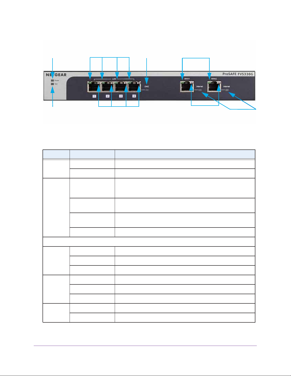
Front Panel
Viewed from left to right, the VPN firewall front panel contains the following ports:
• LAN Ethernet ports. Four switched N-way automatic speed negotiating, Auto
MDI/MDIX, Gigabit Ethernet ports with RJ-45 connectors
• WAN Ethernet ports. Two independent N-way automatic speed negotiating, Auto
MDI/MDIX, Gigabit Ethernet ports with RJ-45 connectors
The front panel also contains three groups of status LEDs, including Power and Test LEDs,
LAN LEDs, and WAN LEDs, all of which are described in the following table.
Get an Overview of the Features and Hardware and Log In
18
ProSAFE Dual WAN Gigabit WAN SSL VPN Firewall FVS336Gv2
Power LED
Test LED
Left LAN LEDs
Right LAN LEDs
DMZ LED
Left WAN LEDs
Right WAN LEDs
Internet
LEDs
Figure 1. Front panel
Table 1. LED descriptions
LED Activity Description
Power Green Power is supplied to the VPN firewall.
Off Power is not supplied to the VPN firewall.
Test Amber during startup Test mode. The VPN firewall is initializing. After approximately two
minutes, when the VPN firewall has completed its initialization, the Test
LED turns off.
Amber during any
other time
Blinking amber The VPN firewall is writing to flash memory during a firmware upgrade or
Off The VPN firewall has booted successfully.
LAN Ports
Left LED Green The LAN port detects a link with a connected Ethernet device.
Blinking green The LAN port receives or transmits data.
Off The LAN port has no link.
Right LED Green The LAN port operates at 1000 Mbps.
Amber The LAN port operates at 100 Mbps.
Off The LAN port operates at 10 Mbps.
DMZ LED Green LAN port 4 operates as a dedicated hardware DMZ port.
Off LAN port 4 operates as a normal LAN port.
The initialization failed or a hardware failure occurred.
when you reset the VPN firewall to defaults.
Get an Overview of the Features and Hardware and Log In
19
ProSAFE Dual WAN Gigabit WAN SSL VPN Firewall FVS336Gv2
Table 1. LED descriptions (continued)
LED Activity Description
WAN Ports
Left LED Green The WAN port has a valid connection with a device that provides an
Internet connection.
Blinking green The WAN port receives or transmits data.
Off The WAN port has no physical link, that is, no Ethernet cable is plugged
into the VPN firewall.
Right LED Green The WAN port operates at 1000 Mbps.
Amber The WAN port operates at 100 Mbps.
Off The WAN port operates at 10 Mbps.
Internet LED Green The WAN port has a valid Internet connection.
Amber The Internet link is down because the WAN port is in standby mode for
failover. Also, before the connection is up, there is an amber color for a
short period of time.
Off The WAN port is either not enabled or has no link to the Internet.
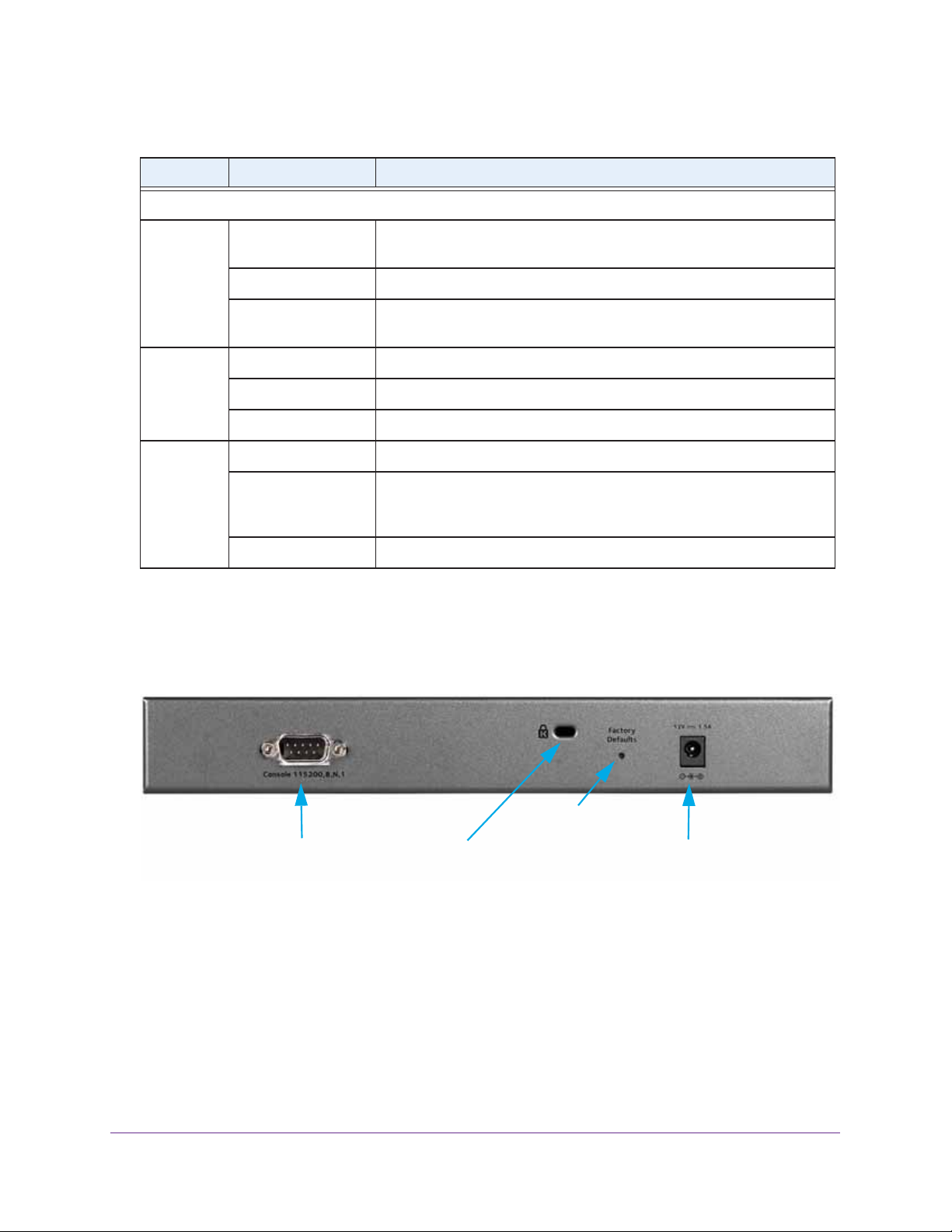
Back Panel
The back panel of the VPN firewall includes a console port, a cable security lock receptacle,
a recessed Factory Defaults reset button, and an AC power connection.
Factory Defaults
reset button
Console port
Cable security
lock receptcle
Figure 2. Back panel
Viewed from left to right, the back panel contains the following components:
• Console port. Port for connecting to an optional console terminal. The port has a DB9
male connector. The default baud rate is 115200 K. The pinouts are (2) Tx, (3) Rx, (5) and
(7) Gnd. For information about accessing the command-line interface (CLI) using the
console port, see
Use the Command-Line Interface on page 537.
• Cable security lock receptacle.
AC power
receptacle
Get an Overview of the Features and Hardware and Log In
20
ProSAFE Dual WAN Gigabit WAN SSL VPN Firewall FVS336Gv2
• Factory Defaults reset button. To reset the VPN firewall to factory default settings, use
a sharp object to press and hold this button for about eight
seconds until the front panel
Test LED blinks. All configuration settings are lost and the default password is restored.
• AC power receptacle. (12V, 1.5A).
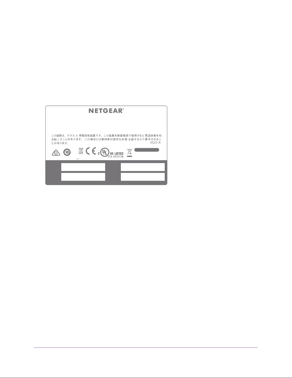
Bottom Panel with Product Label
The product label on the bottom of the VPN firewall’s enclosure displays factory default
settings, regulatory compliance, and other information.
Dual WAN Gigabit SSL VPN Firewall FVS336G v3
This device complies with part 15 of the FCC Rules and Canada ICES-003. Operation is subject to the
following two conditions: (1) this device may not cause harmful interference, and (2) this device must
accept any interference received, including interference that may cause undesired operation.
CAN ICES-3 (A)/NMB-3(A)
DEFAULT ACCESS
https://192.168.1.1
Input Rating: DC 12V 1.5A
MAC
(internet-1)
MAC
(local)
KCC-NGR-FVS336Gv3 (A)
(internet-2)
Made in China
MAC
SERIAL
Figure 3. Product label on the bottom panel
user name: admin
password: password
272-11992-03
Choose a Location for the VPN Firewall
The VPN firewall is suitable for use in an office environment where it can be freestanding (on
its runner feet) or mounted into a standard 19-inch equipment rack. Alternatively, you can
rack-mount the VPN firewall in a wiring closet or equipment room.
Consider the following when deciding where to position the VPN firewall:
• The unit is accessible, and cables can be connected easily.
• Cabling is away from sources of electrical noise. These include lift shafts, microwave
ovens, and air-conditioning units.
• Water or moisture cannot enter the case of the unit.
• Airflow around the unit and through the vents in the side of the case is not restricted.
Provide a minimum of 25 mm or 1-inch clearance.
• The air is as free of dust as possible.
• Temperature operating limits are not likely to be exceeded. Install the unit in a clean,
air-conditioned environment. For information about the recommended operating
temperatures for the VPN firewall, see
Specifications.
Appendix D, Default Settings and Technical
Get an Overview of the Features and Hardware and Log In
21
ProSAFE Dual WAN Gigabit WAN SSL VPN Firewall FVS336Gv2
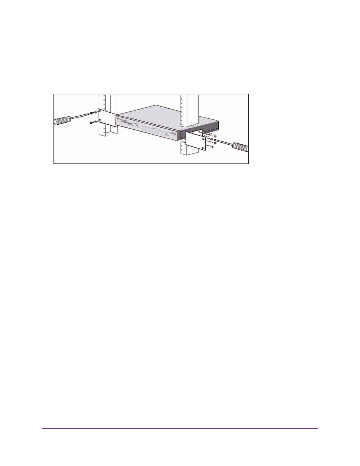
Rack-Mount the VPN Firewall with the Mounting Kit
Use the mounting kit for the VPN firewall to install the appliance in a rack. Attach the
mounting brackets using the hardware that is supplied with the mounting kit.
Figure 4. Rack-mounting
Before mounting the VPN firewall in a rack, verify the following:
• You have the correct screws (supplied with the installation kit).
• The rack onto which you plan to mount the VPN firewall is suitably located.
Login Requirements
Before you can log in to VPN firewall, install the VPN firewall in your network by connecting
the cables and restarting your network according to the instructions in the ProSAFE Dual
WAN Gigabit SSL VPN Firewall FVS336Gv2 Installation Guide. You can download a PDF of
this guide from
Browser Requirements
To connect to and configure the VPN firewall, you must use the latest version of a web
browser such as Google Chrome, Microsoft Internet Explorer, Mozilla Firefox, or Apple Safari
with JavaScript, cookies, and SSL enabled.
Although these web browsers are qualified for use with the VPN firewall’s web management
interface, SSL VPN users must choose a browser that supports JavaScript, Java, cookies,
SSL, and ActiveX to take advantage of the full suite of applications. Java is required only for
the SSL VPN portal, not for the web management interface.
downloadcenter.netgear.com.
Get an Overview of the Features and Hardware and Log In
22
ProSAFE Dual WAN Gigabit WAN SSL VPN Firewall FVS336Gv2
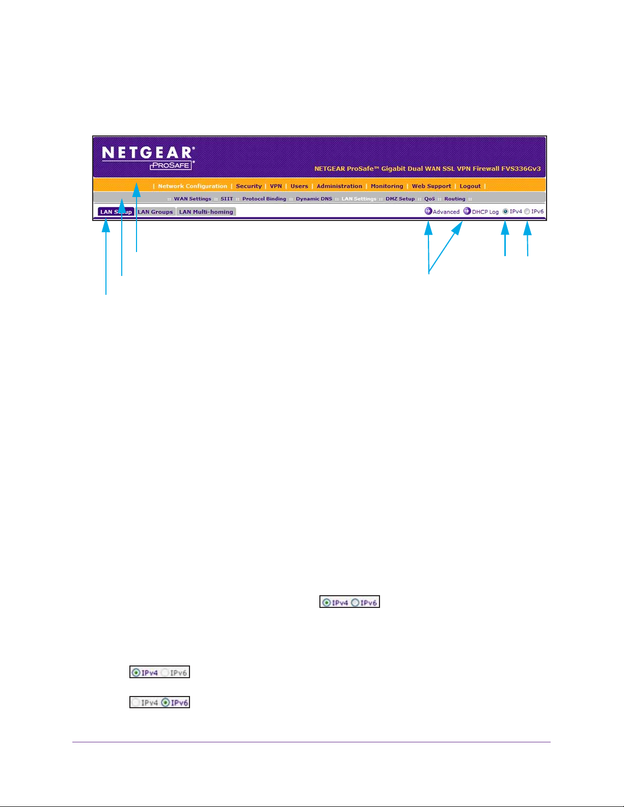
Web Management Interface Overview
The following figure shows the menu at the top the web management interface:
First Level: Main navigation menu link (orange)
Second level: Configuration menu link (gray)
Third level: Submenu tab (blue)
Figure 5. Screen menus, option arrows, and buttons
Option arrows:
Additional screen for submenu item
IP radio buttons
The web management interface menu consists of the following levels and components:
• First level: Main navigation menu links. The main navigation menu in the orange bar
across the top of the web management interface provides access to all the configuration
functions of the VPN firewall and remains constant. When you select a main navigation
menu link, the letters are displayed in white against an orange background.
• Second level: Configuration menu links. The configuration menu links in the gray bar
(immediately below the main navigation menu bar) change according to the main
navigation menu link that you select. When you select a configuration menu link, the
letters are displayed in white against a gray background.
• Third level: Submenu tabs. Each configuration menu item has one or more submenu
tabs that are listed below the gray menu bar. When you select a submenu tab, the text is
displayed in white against a blue background.
• Option arrows. On the right side of a screen, a white arrow in a blue circle precedes a
link in blue letters against a white background. This link provides access to additional
screens for a submenu item.
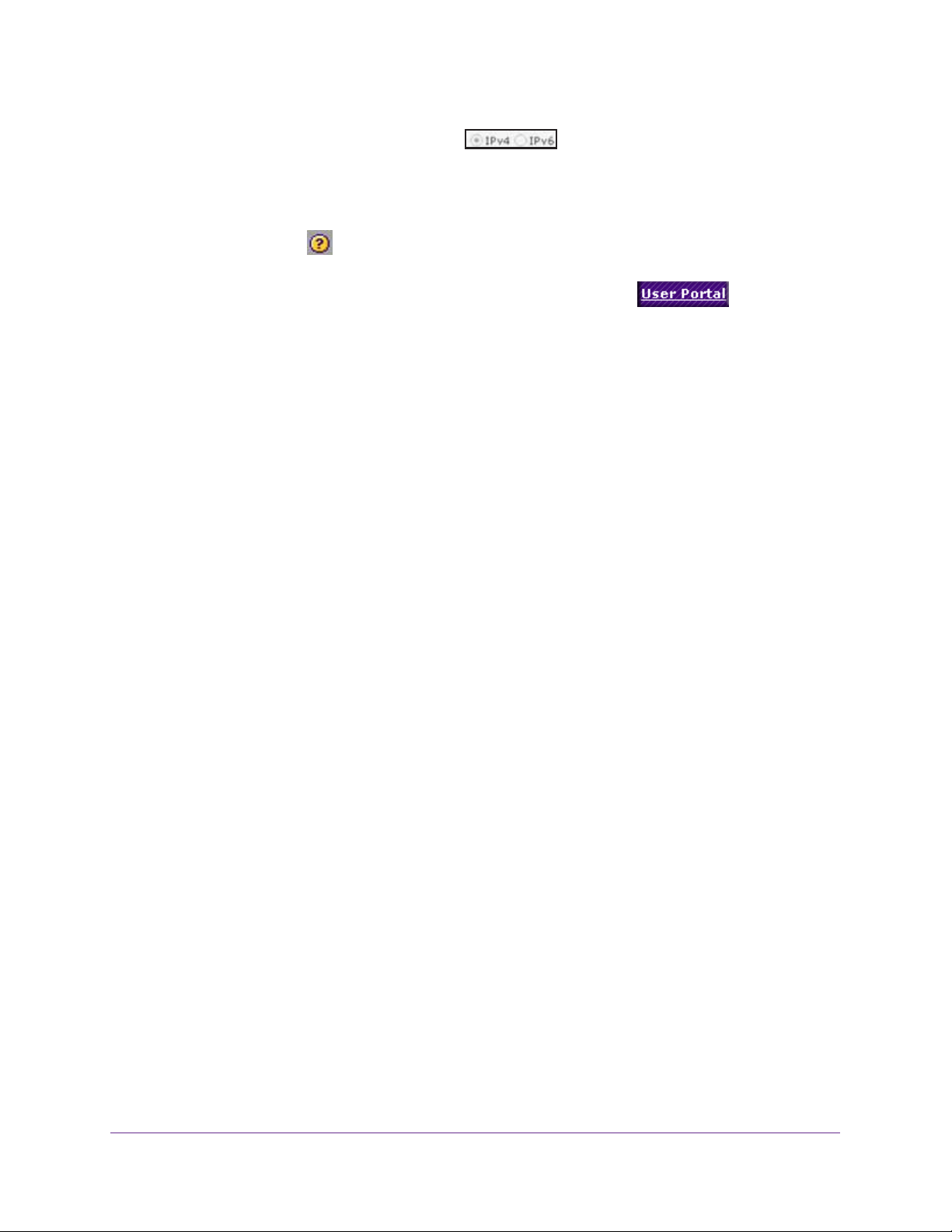
• IP radio buttons. The IPv4 and IPv6 radio buttons let you select the IP version for the
feature to be configured onscreen. Four situations can occur:
- Both radio buttons are operational. You can configure the feature
onscreen for IPv4 functionality or for IPv6 functionality. After you have correctly
configured the feature for both IP versions, the feature can function with both IP
versions simultaneously.
- The IPv4 radio button is operational but the IPv6 radio button is disabled.
You can configure the feature onscreen for IPv4 functionality only.
- The IPv6 radio button is operational but the IPv4 radio button is disabled.
You can configure the feature onscreen for IPv6 functionality only.
Get an Overview of the Features and Hardware and Log In
23
ProSAFE Dual WAN Gigabit WAN SSL VPN Firewall FVS336Gv2
- Both radio buttons are disabled. IP functionality does not apply.
The bottom of each screen provides action buttons. The nature of a screen determines which
action buttons are shown.
Most screens and sections of screens provide an accompanying help screen. To open the
help screen, click the
All screens that you can access from the SSL VPN menu of the web management interface
display a user portal link in the upper right, above the menu bars (
When you click the User Portal link, the SSL VPN default portal opens. This user portal is not
the same as a custom SSL portal login screen that you can build with the SSL VPN Wizard
(see
Build an SSL Portal Using the SSL VPN Wizard on page 427) or manually (see
Manually Set Up or Change an SSL Portal on page 446).
icon.
).
Requirements for Entering IP Addresses
To connect to the VPN firewall, your computer must be configured to obtain an IP address
automatically from the VPN firewall, either an IPv4 address through DHCP or an IPv6
address through DHCPv6, or both.
IPv4 Requirements
The fourth octet of an IP address must be between 0 and 255 (both inclusive). This
requirement applies to any IP address that you enter on a screen of the web management
interface.
IPv6 Requirements
IPv6 addresses are denoted by eight groups of hexadecimal quartets that are separated by
colons. Any four-digit group of zeros within an IPv6 address can be reduced to a single zero
or altogether omitted.
The following errors invalidate an IPv6 address:
• More than eight groups of hexadecimal quartets
• More than four hexadecimal characters in a quartet
• More than two colons in a row
For information about restricted IPv6 address, visit the following Internet Assigned Numbers
Authority (IANA) web page:
http://www.iana.org/assignments/ipv6-address-space/ipv6-address-space.xhtml.
Log In to the VPN Firewall as an Administrator
For you to be able to configure the VPN firewall, you must log in initially as an administrator
(admin).
Get an Overview of the Features and Hardware and Log In
24
ProSAFE Dual WAN Gigabit WAN SSL VPN Firewall FVS336Gv2
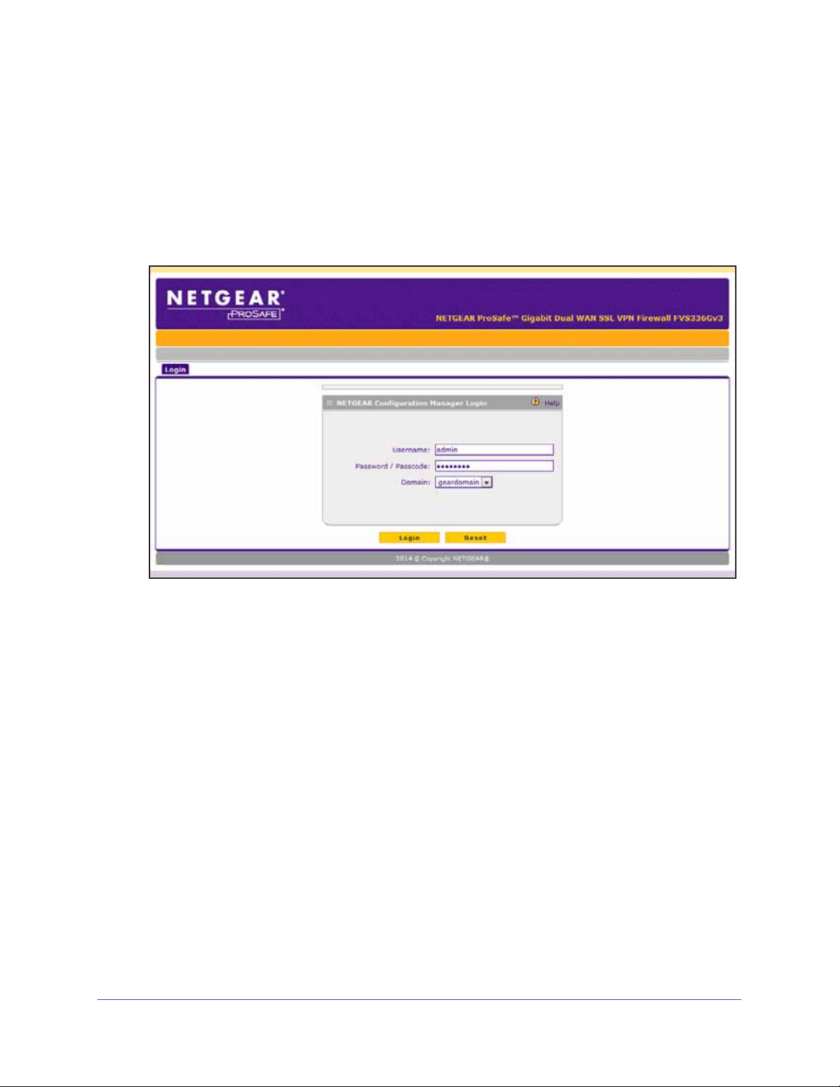
To log in to the VPN firewall:
1. On your computer, launch an Internet browser.
2. In the address field of your browser, enter the IP address that was assigned to the VPN
firewall during the installation process.
The VPN firewall factory default IP address is 192.168.1.1.
The NETGEAR Configuration Manager Login screen displays.
If you connect remotely to the VPN firewall with a browser through an SSL connection for
the first time, you might get a message about the SSL certificate.
3. If you get a message about the SSL certificate, follow the directions of your browser to
accept the SSL certificate.
4. In the Username field, type admin.
Use lowercase letters.
5. In the Password / Passcode field, type password.
Use lowercase letters.
Note: In the Domain menu, leave the domain at geardomain.
6. Click the Login button.
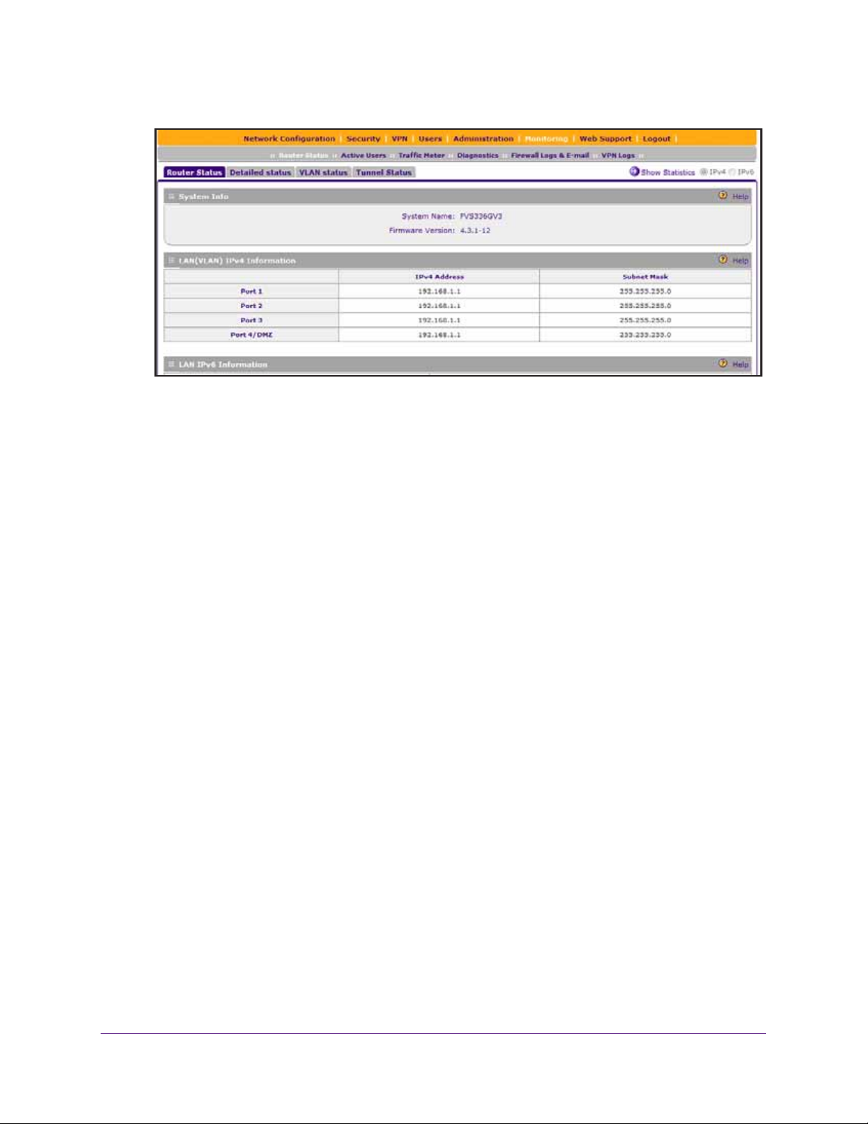
The web management interface displays, showing the Router Status screen. The
following figure shows the top part of the Router Status screen. For more information, see
View the System Status on page 582.
Get an Overview of the Features and Hardware and Log In
25
ProSAFE Dual WAN Gigabit WAN SSL VPN Firewall FVS336Gv2
Note: After five minutes of inactivity (the default login time-out), you are
automatically logged out.
You are now ready to configure the VPN firewall for your specific network environment.
However, NETGEAR recommends that you first change the password for the default
administrator account to a secure password.
Change the Password for the Default Administrator Account
The most secure password does not contain dictionary words from any language and is a
mixture of letters (both uppercase and lowercase), numbers, and selected special characters.
The password can be up to 32
space nor any of the following special characters:
` ~ ! # $ & * ( ) - + | \ ; : ' " < >
To modify the password for the default administrator account from default settings to
secure settings:
1. On your computer, launch an Internet browser.
2. In the address field of your browser, enter the IP address that was assigned to the VPN
firewall during the installation process.
The VPN firewall factory default IP address is 192.168.1.1.
characters in length. However, the password cannot contain a
The NETGEAR Configuration Manager Login screen displays.
3. In the Username field, type admin.
4. In the Password / Passcode field, type password.
5. Click the Login button.
The Router Status screen displays.
Get an Overview of the Features and Hardware and Log In
26
ProSAFE Dual WAN Gigabit WAN SSL VPN Firewall FVS336Gv2
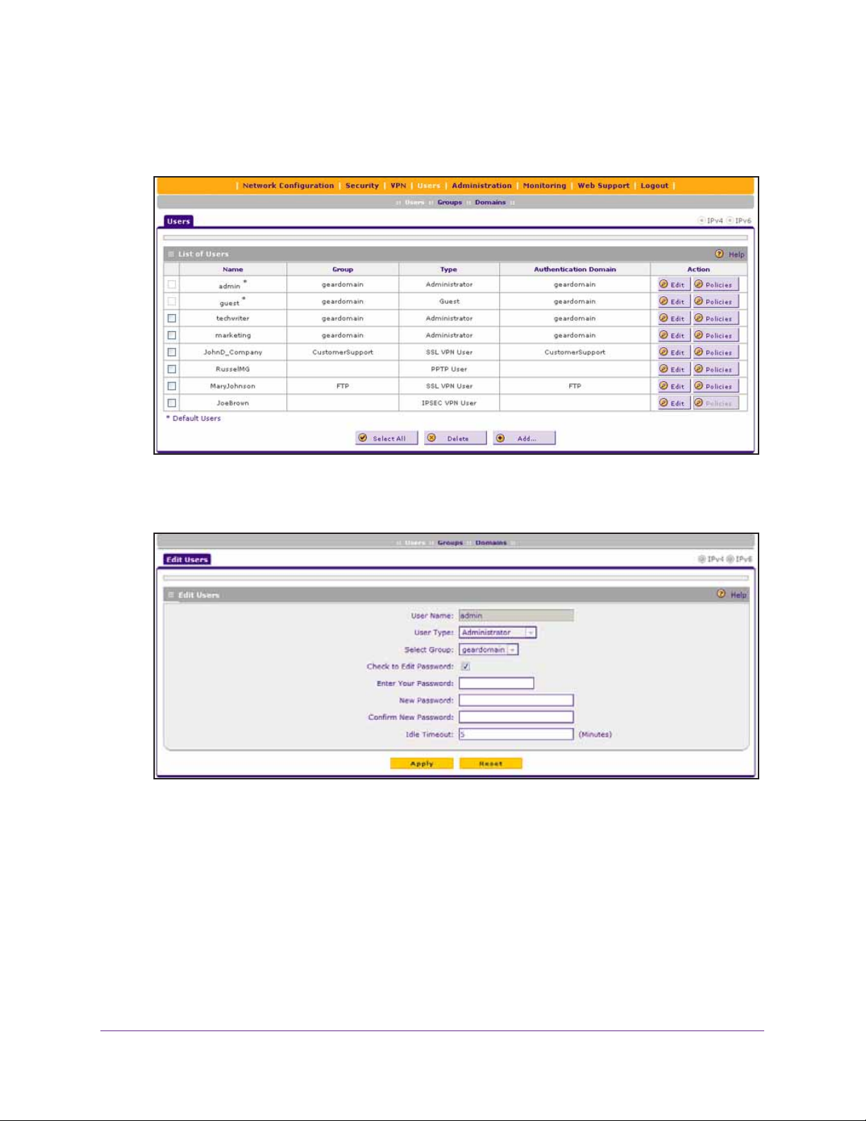
6. Select Users > Users.
The Users screen displays.
7. In the List of Users table, click the Edit button for the admin default user.
The Edit Users screen displays.
8. Select the Check to Edit Password check box.
9. Configure a new password:
• In the Enter Y our Password field, type admin.
• In the New Password field, type a new and secure password.
• In the Confirm New Password field, repeat the new password.
10. Click the Apply button.
Your settings are saved.
Get an Overview of the Features and Hardware and Log In
27

2. Configure the IPv4 Internet and
WAN Settings
This chapter explains how to configure the IPv4 Internet and WAN settings. The chapter
contains the following sections:
• Roadmap to Setting Up IPv4 Internet Connections to Your ISPs
• Configure the IPv4 Internet Connection and WAN Settings
• Configure Load Balancing or Auto-Rollover for IPv4 Interfaces
• Manage Secondary IPv4 WAN Addresses
• Manage Dynamic DNS Connections
• Managing Advanced WAN Options
• Manage WAN QoS and WAN QoS Profiles
• Additional WAN-Related Configuration Tasks
• What to Do Next
2
28

ProSAFE Dual WAN Gigabit WAN SSL VPN Firewall FVS336Gv2
Roadmap to Setting Up IPv4 Internet Connections to Your ISPs
Typically, the VPN firewall is installed as a network gateway to function as a combined LAN
switch and firewall to protect the network from incoming threats and provide secure
connections. To complement the firewall protection, NETGEAR recommends that you use a
gateway security appliance such as a NETGEAR ProSECURE® STM appliance.
The tasks that are required to complete the Internet connection of your VPN firewall depend
on whether you use an IPv4 connection, an IPv6 connection, or both to your Internet service
provider (ISP). For information about setting up an IPv6 connection, see
Configure the IPv6 Internet and WAN Settings.
Note: The VPN firewall supports simultaneous IPv4 and IPv6 connections.
Chapter 3,
Setting up IPv4 Internet connections to your ISP or ISPs includes seven tasks, five of which
are optional.
Complete these tasks:
1. Configure the IPv4 routing mode. Select either NAT or classical routing.
This task is described in Manage the IPv4 WAN Routing Mode on page 30.
2. Configure the IPv4 Internet connections to your ISPs. Connect to one or more ISPs by
configuring up to two WAN interfaces.
You have four configuration options. These tasks are described in the following sections:
• Let the VPN Firewall Automatically Detect and Configure an IPv4 Internet Connection
on page 32
• Manually Configure a Static IPv4 Internet Connection on page 36
• Manually Configure a PPPoE IPv4 Internet Connection on page 39
• Manually Configure a PPTP IPv4 Internet Connection on page 44
3. (Optional) Configure either load balancing or auto-rollover. By default, the WAN
interfaces are configured for primary (single) WAN mode. You can select load balancing
or auto-rollover and a failure detection method. If you configure load balancing, you can also
configure protocol binding.
This task is described in Configure Load Balancing or Auto-Rollover for IPv4 Interfaces
on page 48.
4. (Optional) Configure secondary WAN addresses on the WAN interfaces. Configure
aliases for each WAN interface.
This task is described in Manage Secondary IPv4 WAN Addresses on page 59.
5. (Optional) Configure Dynamic DNS on the WAN interfaces. If necessary, configure your
fully qualified domain names.
Configure the IPv4 Internet and WAN Settings
29

ProSAFE Dual WAN Gigabit WAN SSL VPN Firewall FVS336Gv2
This task is described in Manage Dynamic DNS Connections on page 63.
6. (Optional) Configure advanced WAN options. If necessary, change the factory default
MTU size, port speed and duplex settings, advertised MAC address of the VPN firewall, and
WAN connection type and corresponding upload and download connection speeds. These
are advanced features, and you usually do not need to change the settings.
These tasks are described in Managing Advanced WAN Options on page 66.
7. (Optional) Configure the WAN traffic meters.
This task is described in Configure and Enable the WAN IPv4 Traffic Meter on page 558.
Configure the IPv4 Internet Connection and WAN Settings
To set up your VPN firewall for secure IPv4 Internet connections, you must determine the
IPv4 WAN mode (see
Internet connection to your ISP on the WAN ports.
The following sections provide information about configuring the IPv4 Internet connection and
WAN settings:
Manage the IPv4 WAN Routing Mode) and then configure the IPv4
• Manage the IPv4 WAN Routing Mode
• Let the VPN Firewall Automatically Detect and Configure an IPv4 Internet Connection
• Manually Configure a Static IPv4 Internet Connection
• Manually Configure a PPPoE IPv4 Internet Connection
• Manually Configure a PPTP IPv4 Internet Connection
Manage the IPv4 WAN Routing Mode
By default, IPv4 is supported and functions in NAT mode but can also function in classical
routing mode. IPv4 functions the same way in IPv4-only mode that it does in IPv4/IPv6 mode.
The latter mode adds IPv6 functionality (see
The following sections provide information about managing the IPv4 routing mode:
• Network Address Translation Overview
• Classical Routing
• Change the IPv4 WAN Routing Mode
Network Address Translation Overview
Network Address T ranslation (NAT) allows all computers on your LAN to share a single public
Internet IP address. From the Internet, only a single device (the VPN firewall) and a single IP
address exist. Computers on your LAN can use any private IP address range, and these IP
addresses are not visible from the Internet.
Manage the IPv6 Routing Mode on page 88).
Configure the IPv4 Internet and WAN Settings
30

ProSAFE Dual WAN Gigabit WAN SSL VPN Firewall FVS336Gv2
Note the following about NAT:
• The VPN firewall uses NAT to select the correct computer (on your LAN) to receive any
incoming data.
• If you have only a single public Internet IP address, you must use NAT (the default
setting).
• If your ISP has provided you with multiple public IP addresses, you can use one address
as the primary shared address for Internet access by your computers, and you can map
incoming traffic on the other public IP addresses to specific computers on your LAN. This
one-to-one inbound mapping is configured using an inbound firewall rule.
Classical Routing
In classical routing mode, the VPN firewall performs routing, but without NA T. To gain Internet
access, each computer on your LAN must have a valid static Internet IP address.
If your ISP has allocated a number of static IP addresses to you and you have assigned one
of these addresses to each computer, you can choose classical routing. Or you can use
classical routing to route private IP addresses within a campus environment.
Change the IPv4 WAN Routing Mode
The following procedure describes how to change the IPv4 routing mode. By default, the
VPN firewall functions in NAT mode.
To change the IPv4 routing mode:
1. On your computer, launch an Internet browser.
2. In the address field of your browser, enter the IP address that was assigned to the VPN
firewall during the installation process.
The VPN firewall factory default IP address is 192.168.1.1.
The NETGEAR Configuration Manager Login screen displays.
3. In the Username field, type your user name and in the Password / Passcode field, type
your password.
For the default administrative account, the default user name is admin and the default
password is password.
4. If you changed the default domain or were assigned a domain, from the Domain menu,
select the domain.
If you did not change the domain or were not assigned a domain, leave the menu
selection at geardomain.
5. Click the Login button.
The Router Status screen displays.
6. Select Network Configuration > WAN Settings > WAN Mode.
The WAN Mode screen displays.
Configure the IPv4 Internet and WAN Settings
31

ProSAFE Dual WAN Gigabit WAN SSL VPN Firewall FVS336Gv2
7. In the NAT (Network Address Translation) section, select the NAT radio button or the
Classical Routing radio button.
WARNING:
Changing the WAN mode causes all LAN WAN and DMZ WAN
inbound rules to revert to default settings.
8. Click the Apply button.
Your settings are saved. The settings apply to all WAN ports.
Let the VPN Firewall Automatically Detect and Configure an IPv4 Internet Connection
The following procedure describes how you can let your ISP automatically configure the IPv4
WAN addresses of the VPN firewall through a DHCP server.
If your ISP does not support automatic configuration through a DHCP server, you must obtain
configuration parameters from your ISP to be able to establish an Internet connection
manually. For information about manually configuring the IPv4 WAN addresses, see the
following sections:
• Manually Configure a Static IPv4 Internet Connection
• Manually Configure a PPPoE IPv4 Internet Connection
• Manually Configure a PPTP IPv4 Internet Connection
Configure the IPv4 Internet and WAN Settings
32

ProSAFE Dual WAN Gigabit WAN SSL VPN Firewall FVS336Gv2
Note: If your ISP requires MAC authentication and another MAC address was
previously registered with your ISP, you must configure that MAC address
on the VPN firewall (see
Change the Advertised MAC Address of the VPN
Firewall on page 70) before you begin the following procedure.
To automatically configure a WAN port for an IPv4 Internet connection:
1. On your computer, launch an Internet browser.
2. In the address field of your browser, enter the IP address that was assigned to the VPN
firewall during the installation process.
The VPN firewall factory default IP address is 192.168.1.1.
The NETGEAR Configuration Manager Login screen displays.
3. In the Username field, type your user name and in the Password / Passcode field, type
your password.
For the default administrative account, the default user name is admin and the default
password is password.
4. If you changed the default domain or were assigned a domain, from the Domain menu,
select the domain.
If you did not change the domain or were not assigned a domain, leave the menu
selection at geardomain.
5. Click the Login button.
The Router Status screen displays.
6. Select Network Configuration > WAN Settings > WAN Setup.
The WAN Setup screen displays the IPv4 settings.
The IPv4 WAN Settings table displays the following fields:
• WAN. The WAN interface (WAN1 or WAN2).
• Status. The status of the WAN interface (UP or DOWN).
• WAN IP. The IPv4 address of the WAN interface.
Configure the IPv4 Internet and WAN Settings
33

ProSAFE Dual WAN Gigabit WAN SSL VPN Firewall FVS336Gv2
• Failure Detection Method. The failure detection method that is active for the WAN
interface (see
Configure the Auto-Rollover Mode and Failure Detection Method for
IPv4 Interfaces on page 56).
Any of the following methods can be displayed: None, DNS Lookup (WAN DNS
Servers), DNS Lookup (the configured IP address is displayed), or PING (the
configured IP address is displayed).
• Action. The Edit button provides access to the WAN IPv4 ISP Settings screen (see
Step 7) for the corresponding WAN interface; the Status button provides access to
the Connection Status screen (see Step 9) for the corresponding WAN interface.
7. In the IPv4 WAN Settings table, click the Edit button for the WAN interface for which you
want to let the VPN firewall automatically configure the connection to the Internet.
The WAN IPv4 ISP Settings screen displays. The following figure shows the WAN2 IPv4
ISP Settings screen as an example.
Configure the IPv4 Internet and WAN Settings
34

ProSAFE Dual WAN Gigabit WAN SSL VPN Firewall FVS336Gv2
8. Click the Auto Detect button.
The autodetect process probes the WAN port for a range of connection methods and
suggests one that your ISP is most likely to support.
The autodetect process returns one of the following results:
• If the autodetect process is successful, a status bar at the top of the screen displays
the results (for example, DHCP service detected).
• If the autodetect process senses a dynamic DHCP, PPPoE, or PPTP connection that
requires input from you, it prompts you for the information. With auto detection, it can
detect if it is a static line. Then the user needs to enter a static IP address.
The following table lists the settings that you might have to enter:
Connection Method Data You Might Have to Enter Manually
Dynamic DHCP • Client Identifier. If your ISP requires client identifier information to assign
an IP address using DHCP, select the Client Identifier check box and
enter the client identifier information in the field.
• Vendor Class Identifier. If your ISP requires the vendor class identifier
information to assign an IP address using DHCP, select the Vendor Class
Identifier check box.
PPPoE • Login
• Password
• Account Name
• Domain Name
PPTP • Login
• Password
• Account Name
• Domain Name
• My IP Address
• Server IP Address
• If the autodetect process does not find a connection, you are prompted either to
check the physical connection between your VPN firewall and the cable, DSL line, or
satellite or wireless Internet dish, or to check your VPN firewall’s MAC address (see
Managing Advanced WAN Options on page 66).
9. Verify the connection:
a. Select Network Configuration > WAN Settings > WAN Setup.
The WAN Setup screen displays the IPv4 settings (see the figure that is shown in
Step 6).
b. In the IPv4 WAN Settings table, click the Status button for the WAN interface for
which you want to display the connection status.
The Connection Status pop-up screen displays. The following figure shows a static IP
address configuration.
Configure the IPv4 Internet and WAN Settings
35
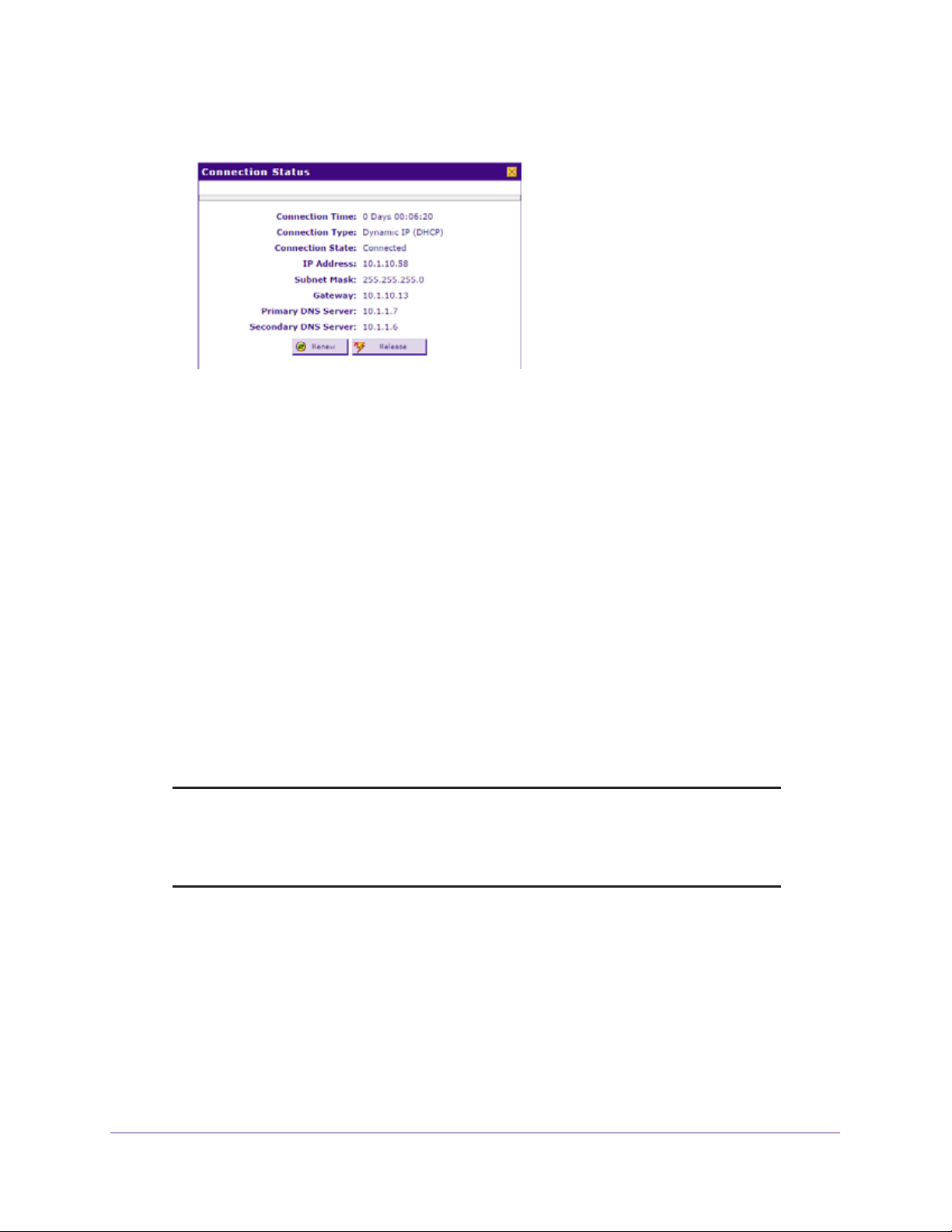
ProSAFE Dual WAN Gigabit WAN SSL VPN Firewall FVS336Gv2
The Connection Status screen shows a valid IP address and gateway. You are
connected to the Internet. For more information about the connection status, see
View the WAN Port Status and Terminate or Establish the Internet Connection on
page 594.
If the configuration was not successful, try to manually configure the connection. For
more information, see the following sections:
• Manually Configure a Static IPv4 Internet Connection on page 36
• Manually Configure a PPPoE IPv4 Internet Connection on page 39
• Manually Configure a PPTP IPv4 Internet Connection on page 44
Manually Configure a Static IPv4 Internet Connection
To configure a static IPv4 Internet connection, enter the IPv4 address information that your
IPv4 ISP gave you. If you do not have this information, contact your IPv4 ISP. For each WAN
interface, you need the following information: IP address, IP subnet mask, and IP addresses
of the gateway, primary DNS server, and secondary DNS server.
Note: If your ISP requires MAC authentication and another MAC address was
previously registered with your ISP, you must configure that MAC address
on the VPN firewall (see
Firewall) before you begin the following procedure.
T o manually configure and verify a static IPv4 Internet connection for a WAN interface:
1. On your computer, launch an Internet browser.
2. In the address field of your browser, enter the IP address that was assigned to the VPN
firewall during the installation process.
Change the Advertised MAC Address of the VPN
The VPN firewall factory default IP address is 192.168.1.1.
The NETGEAR Configuration Manager Login screen displays.
Configure the IPv4 Internet and WAN Settings
36

ProSAFE Dual WAN Gigabit WAN SSL VPN Firewall FVS336Gv2
3. In the Username field, type your user name and in the Password / Passcode field, type
your password.
For the default administrative account, the default user name is admin and the default
password is password.
4. If you changed the default domain or were assigned a domain, from the Domain menu,
select the domain.
If you did not change the domain or were not assigned a domain, leave the menu
selection at geardomain.
5. Click the Login button.
The Router Status screen displays.
6. Select Network Configuration > WAN Settings > WAN Setup.
The WAN Setup screen displays the IPv4 settings.
7. In the IPv4 WAN Settings table, click the Edit button for the WAN interface that you want to
configure.
The WAN IPv4 ISP Settings screen displays.
8. In the Internet (IP) Address section, select the Use Static IP Address radio button.
9. Configure the IP address settings as described in the following table.
Setting Description
IP Address The static IP address assigned to you. This address identifies the VPN firewall to
your ISP.
Configure the IPv4 Internet and WAN Settings
37
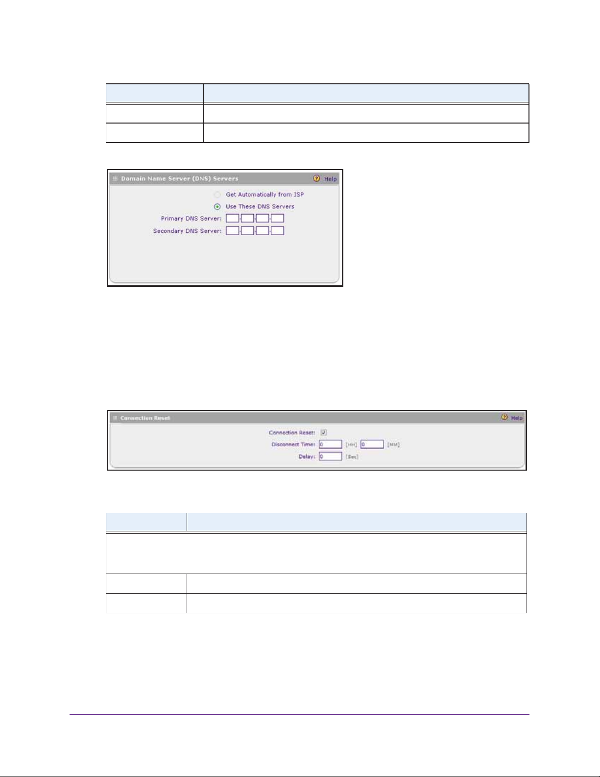
ProSAFE Dual WAN Gigabit WAN SSL VPN Firewall FVS336Gv2
Setting Description
IP Subnet Mask The subnet mask is usually provided by your ISP.
Gateway IP Address The IP address of the ISP’s gateway is usually provided by your ISP.
10. Locate the Domain Name Server (DNS) Servers section.
Note: When you selected the Use Static IP Address radio button in Step 8, the
Use These DNS Servers radio button was selected automatically.
11. Specify the DNS server addresses:
• Primary DNS Server. The IP address of the primary DNS server.
• Secondary DNS Server. The IP address of the secondary DNS server.
12. Locate the Connection Reset section.
13. To configure an automatic connection reset, specify the settings as described in the
following table.
Setting Description
Select the Connection Reset check box to specify a time when the WAN connection is reset, that is, the
connection is disconnected momentarily and then reestablished. Then specify the disconnect time and
delay.
Disconnect Time Specify the hour and minutes when the connection must be disconnected.
Delay Specify the period in seconds after which the connection must be reestablished.
14. Click the Apply button.
Your settings are saved.
15. To evaluate your entries, click the Test button.
Configure the IPv4 Internet and WAN Settings
38

ProSAFE Dual WAN Gigabit WAN SSL VPN Firewall FVS336Gv2
The VPN firewall attempts to make a connection according to the settings that you
entered.
16. Verify the connection:
a. Select Network Configuration > WAN Settings > WAN Setup.
The WAN Setup screen displays the IPv4 settings.
b. In the IPv4 WAN Settings table, click the Status button for the WAN interface for
which you want to display the connection status.
The Connection Status pop-up screen displays.
The Connection Status screen shows a valid IP address and gateway. You are
connected to the Internet.
Note: If the configuration was not successful, see Troubleshoot the ISP
Connection on page 615.
Manually Configure a PPPoE IPv4 Internet Connection
If you installed login software, your connection type is most likely PPPoE. To configure a
PPPoE IPv4 Internet connection, enter the PPPoE IPv4 information that your IPv4 ISP gave
you. If you do not have this information, contact your IPv4 ISP.
For each WAN interface, you need the following information: login name, login password,
and if applicable, account name and domain name. If your ISP assigns you a static IP
address, you also need the IP address, IP subnet mask, and IP addresses of the primary
DNS server and secondary DNS server.
Configure the IPv4 Internet and WAN Settings
39

ProSAFE Dual WAN Gigabit WAN SSL VPN Firewall FVS336Gv2
Note: If your ISP requires MAC authentication and another MAC address was
previously registered with your ISP, you must configure that MAC address
on the VPN firewall (see
Change the Advertised MAC Address of the VPN
Firewall on page 70) before you begin the following procedure.
To manually configure and verify a PPPoE IPv4 Internet connection for a WAN
interface:
1. On your computer, launch an Internet browser.
2. In the address field of your browser, enter the IP address that was assigned to the VPN
firewall during the installation process.
The VPN firewall factory default IP address is 192.168.1.1.
The NETGEAR Configuration Manager Login screen displays.
3. In the Username field, type your user name and in the Password / Passcode field, type
your password.
For the default administrative account, the default user name is admin and the default
password is password.
4. If you changed the default domain or were assigned a domain, from the Domain menu,
select the domain.
If you did not change the domain or were not assigned a domain, leave the menu
selection at geardomain.
5. Click the Login button.
The Router Status screen displays.
6. Select Network Configuration > WAN Settings > WAN Setup.
The WAN Setup screen displays the IPv4 settings.
7. In the WAN IPv4 Settings table, click the Edit button for the WAN interface that you want to
configure.
The WAN IPv4 ISP Settings screen displays.
8. In the ISP Login section, select the Yes radio button.
Configure the IPv4 Internet and WAN Settings
40

ProSAFE Dual WAN Gigabit WAN SSL VPN Firewall FVS336Gv2
9. Enter the login name in the Login field and the password in the Password field.
This information is provided by your ISP and is specific for the PPPoE service.
10. In the ISP Type section, select the Other (PPPoE) radio button.
11. Enter the PPPoE settings as described in the following table.
Setting Description
Account Name The valid account name for the PPPoE connection.
Domain Name The name of your ISP’s domain or your domain name if your ISP assigned one. You
can leave this field blank.
Idle Timeout To keep the connection always on, select the Keep Connected radio button.
To log out after the connection is idle for a period, select the Idle Timeout radio button
and, in the Idle Timeout field, enter the number of minutes to wait before
disconnecting. This method is useful if your ISP charges you based on the period that
you have logged in.
12. Locate the Internet (IP) Address section.
Configure the IPv4 Internet and WAN Settings
41

ProSAFE Dual WAN Gigabit WAN SSL VPN Firewall FVS336Gv2
13. Configure the IP address settings as described in the following table.
Setting Description
Select an IP address radio button:
• Get Dynamically from ISP. Select this radio button if your ISP has not assigned you a static IP
address. The ISP automatically assigns an IP address to the VPN firewall using the DHCP network
protocol.
• Use Static IP Address. Select this radio button if your ISP has assigned you a static (fixed or
permanent) IP address. Enter the IP address and subnet mask.
IP Address The static IP address assigned to you. This address identifies the VPN firewall to
your ISP.
IP Subnet Mask The subnet mask is usually provided by your ISP.
14. Locate the Domain Name Server (DNS) Servers section.
15. Specify the DNS settings as described in the following table.
Setting Description
Select a Domain Name Server (DNS) IP address radio button:
• Get Automatically from ISP. Select this radio button if your ISP has not assigned you any DNS IP
addresses. The ISP automatically assigns the DNS IP addresses to the VPN firewall using the DHCP
network protocol.
• Use These DNS Servers. Select this radio button if your ISP assigned you static (fixed or permanent)
DNS IP addresses. Enter the IP addresses in the Primary DNS Server and Secondary DNS Server
fields.
Note: Make sure that you enter valid DNS server IP addresses in the fields. Incorrect DNS entries might
cause connectivity issues.
Primary DNS Server The IP address of the primary DNS server.
Secondary DNS Server The IP address of the secondary DNS server.
16. Locate the Connection Reset section.
Configure the IPv4 Internet and WAN Settings
42

ProSAFE Dual WAN Gigabit WAN SSL VPN Firewall FVS336Gv2
17. To configure an automatic connection reset, specify the settings as described in the
following table.
Setting Description
Select the Connection Reset check box to specify a time when the WAN connection is reset, that is, the
connection is disconnected momentarily and then reestablished. Then specify the disconnect time and
delay.
Disconnect Time Specify the hour and minutes when the connection must be disconnected.
Delay Specify the period in seconds after which the connection must be reestablished.
18. Click the Apply button.
Your settings are saved.
19. To evaluate your entries, click the Test button.
The VPN firewall attempts to make a connection according to the settings that you
entered.
20. Verify the connection:
a. Select Network Configuration > WAN Settings > WAN Setup.
The WAN Setup screen displays the IPv4 settings.
b. In the IPv4 WAN Settings table, click the Status button for the WAN interface for
which you want to display the connection status.
The Connection Status pop-up screen displays. The IP addresses that are shown in
this figure are not related to any other examples in this manual.
The Connection Status screen shows a valid IP address and gateway. You are
connected to the Internet.
Note: If the configuration was not successful, see Troubleshoot the ISP
Connection on page 615.
Configure the IPv4 Internet and WAN Settings
43

ProSAFE Dual WAN Gigabit WAN SSL VPN Firewall FVS336Gv2
Manually Configure a PPTP IPv4 Internet Connection
To configure a PPTP IPv4 Internet connection, enter the PPTP IPv4 information that your
IPv4 ISP gave you. If you do not have this information, contact your IPv4 ISP.
For each WAN interface, you need the following information: login name, login password, the
IP address assigned by the ISP to make the connection with the ISP server, the IP address of
the ISP server, and, if applicable, account name and domain name.
If your ISP assigns you a static IP address, you also need the static IP address, IP subnet
mask, and IP addresses of the primary DNS server and secondary DNS server. A static IP
address can be assigned by ISP over PPTP.
Note: If your ISP requires MAC authentication and another MAC address was
previously registered with your ISP, you must configure that MAC address
on the VPN firewall (see
Firewall on page 70) before you begin the following procedure.
Change the Advertised MAC Address of the VPN
T o manually configure and verify a PPTP IPv4 Internet connection for a WAN interface:
1. On your computer, launch an Internet browser.
2. In the address field of your browser, enter the IP address that was assigned to the VPN
firewall during the installation process.
The VPN firewall factory default IP address is 192.168.1.1.
The NETGEAR Configuration Manager Login screen displays.
3. In the Username field, type your user name and in the Password / Passcode field, type
your password.
For the default administrative account, the default user name is admin and the default
password is password.
4. If you changed the default domain or were assigned a domain, from the Domain menu,
select the domain.
If you did not change the domain or were not assigned a domain, leave the menu
selection at geardomain.
5. Click the Login button.
The Router Status screen displays.
6. Select Network Configuration > WAN Settings > WAN Setup.
The WAN Setup screen displays the IPv4 settings.
Configure the IPv4 Internet and WAN Settings
44

ProSAFE Dual WAN Gigabit WAN SSL VPN Firewall FVS336Gv2
7. In the WAN IPv4 Settings table, click the Edit button for the WAN interface that you want
to configure.
The WAN IPv4 ISP Settings screen displays.
8. In the ISP Login section, select the Yes radio button.
9. Enter the login name in the Login field and the password in the Password field.
This information is provided by your ISP and is specific for the PPTP service.
10. In the ISP Type section, select the Austria (PPTP) radio button.
11. Enter the P PT P settings as described in the following table.
Setting Description
Account Name The account name is also known as the host name or system name. Enter the valid
account name for the PPTP connection (usually your email ID assigned by your ISP).
Some ISPs require you to enter your full email address here.
Domain Name Your domain name or workgroup name assigned by your ISP, or your ISP’s domain
name. You can leave this field blank.
Configure the IPv4 Internet and WAN Settings
45

ProSAFE Dual WAN Gigabit WAN SSL VPN Firewall FVS336Gv2
Setting Description
Idle Timeout Select a connection method radio button:
• Keep Connected. Select this radio button to keep the connection always on.
• Idle Timeout. Select this radio button to log out after the connection is idle for a
period. In the Idle Timeout field, enter the number of minutes to wait before
disconnecting. This method is useful if your ISP charges you based on the period
that you have logged in.
My IP Address The IP address assigned by the ISP to make the connection with the ISP server.
Server IP Address The IP address of the PPTP server.
12. Locate the Internet (IP) Address section.
13. Configure the IP address settings as described in the following table.
Setting Description
Select an IP address radio button:
• Get Dynamically from ISP. Select this radio button if your ISP has not assigned you a static IP
address. The ISP automatically assigns an IP address to the VPN firewall using the DHCP network
protocol.
• Use Static IP Address. Select this radio button if your ISP assigned you a static (fixed or permanent)
IP address. Enter the IP address and subnet mask.
IP Address The static IP address assigned to you. This address identifies the VPN firewall to
your ISP.
IP Subnet Mask The subnet mask is usually provided by your ISP.
14. Locate the Domain Name Server (DNS) Servers section.
Configure the IPv4 Internet and WAN Settings
46

ProSAFE Dual WAN Gigabit WAN SSL VPN Firewall FVS336Gv2
15. Specify the DNS settings as described in the following table.
Setting Description
Select a Domain Name Server (DNS) radio button:
• Get Automatically from ISP. Select this radio button if your ISP has not assigned you any DNS IP
addresses. The ISP automatically assigns the DNS IP addresses to the VPN firewall using the DHCP
network protocol.
• Use These DNS Servers. Select this radio button if your ISP assigned you static (fixed or permanent)
DNS IP addresses. Enter the IP addresses in the Primary DNS Server and Secondary DNS Server
fields.
Note: Make sure that you enter valid DNS server IP addresses in the fields. Incorrect DNS entries might
cause connectivity issues.
Primary DNS Server The IP address of the primary DNS server.
Secondary DNS Server The IP address of the secondary DNS server.
16. Locate the Connection Reset section.
17. To configure an automatic connection reset, specify the settings as described in the
following table.
Setting Description
Select the Connection Reset check box to specify a time when the WAN connection is reset, that is, the
connection is disconnected momentarily and then reestablished. Then specify the disconnect time and
delay.
Disconnect Time Specify the hour and minutes when the connection must be disconnected.
Delay Specify the period in seconds after which the connection must be reestablished.
18. Click the Apply button.
Your settings are saved.
19. To evaluate your entries, click the Test button.
The VPN firewall attempts to make a connection according to the settings that you
entered.
20. Verify the connection:
a. Select Network Configuration > WAN Settings > WAN Setup.
The WAN Setup screen displays the IPv4 settings.
b. In the IPv4 WAN Settings table, click the Status button for the WAN interface for
which you want to display the connection status.
Configure the IPv4 Internet and WAN Settings
47

ProSAFE Dual WAN Gigabit WAN SSL VPN Firewall FVS336Gv2
The Connection Status pop-up screen displays. The IP addresses that are shown in
this figure are not related to any other examples in this manual.
The Connection Status screen shows a valid IP address and gateway. You are
connected to the Internet.
Note: If the configuration was not successful, see Troubleshoot the ISP
Connection on page 615.
Configure Load Balancing or Auto-Rollover for IPv4 Interfaces
You can configure the VPN firewall’s IPv4 interfaces on a mutually exclusive basis for either
auto-rollover (for increased system reliability) or load balancing (for maximum bandwidth
efficiency). If you do not select load balancing, you must specify one WAN interface as the
primary interface.
The following sections provide information about configuring load balancing and auto-rollover
for IPv4 interfaces:
• Load Balancing and Auto-Rollover for IPv4 WAN Interfaces
• Configure Load Balancing Mode and Optional Protocol Binding for IPv4 Interfaces
• Configure the Auto-Rollover Mode and Failure Detection Method for IPv4 Interfaces
Load Balancing and Auto-Rollover for IPv4 WAN Interfaces
The VPN firewall supports the following modes for IPv4 interfaces:
• Load balancing mode. The VPN firewall distributes the outbound traffic equally among
the WAN interfaces that are functional. You can configure two WAN interfaces. The VPN
Configure the IPv4 Internet and WAN Settings
48

ProSAFE Dual WAN Gigabit WAN SSL VPN Firewall FVS336Gv2
firewall supports weighted load balancing and round-robin load balancing (see Configure
Load Balancing Mode and Optional Protocol Binding for IPv4 Interfaces on page 49).
Note: Scenarios could arise in which load balancing must be bypassed for
certain traffic or applications. If certain traffic must travel on a specific
WAN interface, configure protocol binding rules for that WAN
interface. The rule must match the desired traffic.
• Primary WAN mode. The selected WAN interface is made the primary interface. The
other three interfaces are disabled.
• Auto-rollover mode. The selected WAN interface is defined as the primary link, and
another interface must be defined as the rollover link. As long as the primary link is up, all
traffic is sent over the primary link. When the primary link goes down, the rollover link is
brought up to send the traffic. When the primary link comes back up, traffic automatically
rolls back to the original primary link.
If you want to use a redundant ISP link for backup purposes, select the WAN port that
must function as the primary link for this mode. Ensure that you also configure the backup
WAN port and that you configure the WAN failure detection method to support
auto-rollover (see
IPv4 Interfaces on page 56).
Configure the Auto-Rollover Mode and Failure Detection Method for
Note: If the VPN firewall functions in IPv4/IPv6 mode, you cannot configure
load balancing. For information about IPv4/IPv6 mode, see
the IPv6 Routing Mode on page 88.
Manage
Configure Load Balancing Mode and Optional Protocol Binding for IPv4 Interfaces
To use two ISP IPv4 links simultaneously, configure load balancing. In load balancing mode,
any WAN port carries any outbound protocol unless you configure protocol binding.
The following sections provide information about configuring load balancing mode and
optional protocol binding for IPv4 interfaces:
• Protocol Binding
• Configure Load Balancing Mode for IPv4 Interfaces
• Configure Protocol Binding Rules for IPv4 Interfaces
• Change a Protocol Binding Rule
• Manage Existing Protocol Binding Rules
Configure the IPv4 Internet and WAN Settings
49

ProSAFE Dual WAN Gigabit WAN SSL VPN Firewall FVS336Gv2
Protocol Binding
When a protocol is bound to a particular WAN port, all outgoing traffic of that protocol is
directed to the bound WAN port. For example, if the HTTPS protocol is bound to the WAN1
port and the FTP protocol is bound to the WAN2 port, the VPN firewall automatically routes
all outbound HTTPS traffic from the computers on the LAN through the WAN1 port. All
outbound FTP traffic is routed through the WAN2 port.
Protocol binding addresses two issues:
• Segregation of traffic between links that are not of the same speed.
High-volume traffic can be routed through the WAN port connected to a high-speed link,
and low-volume traffic can be routed through the WAN port connected to the low-speed
link.
• Continuity of source IP address for secure connections.
Some services, particularly HTTPS, cease to respond when a client’s source IP address
changes shortly after a session is established.
Configure Load Balancing Mode for IPv4 Interfaces
The following procedure describes how to configure load balancing mode, which the VPN
firewall supports only for IPv4 WAN interfaces.
To configure load balancing mode:
1. On your computer, launch an Internet browser.
2. In the address field of your browser, enter the IP address that was assigned to the VPN
firewall during the installation process.
The VPN firewall factory default IP address is 192.168.1.1.
The NETGEAR Configuration Manager Login screen displays.
3. In the Username field, type your user name and in the Password / Passcode field, type
your password.
For the default administrative account, the default user name is admin and the default
password is password.
4. If you changed the default domain or were assigned a domain, from the Domain menu,
select the domain.
If you did not change the domain or were not assigned a domain, leave the menu
selection at geardomain.
5. Click the Login button.
The Router Status screen displays.
6. Select Network Configuration > WAN Settings > WAN Mode.
The WAN Mode screen displays.
Configure the IPv4 Internet and WAN Settings
50
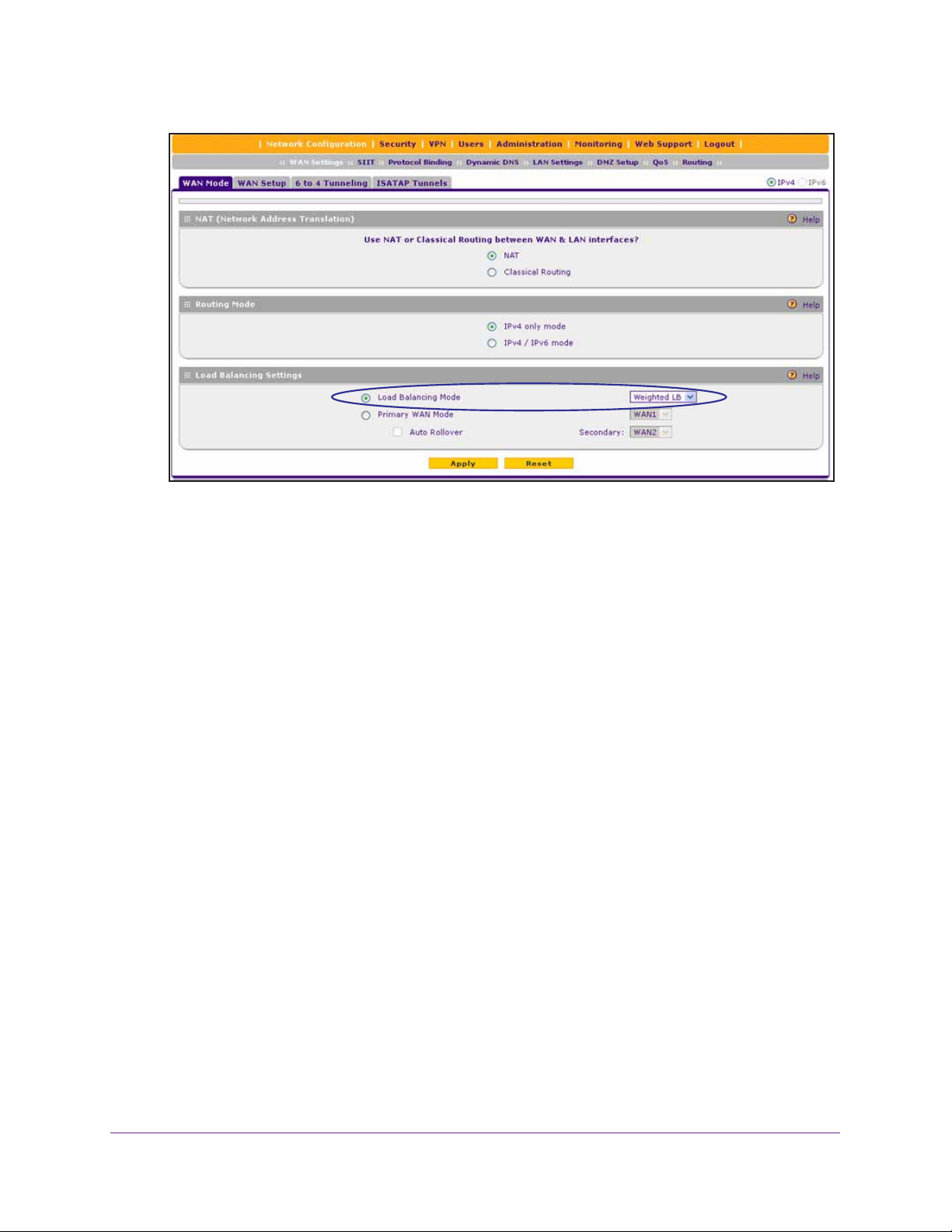
ProSAFE Dual WAN Gigabit WAN SSL VPN Firewall FVS336Gv2
7. In the Load Balancing Settings section, configure the following settings:
a. Select the Load Balancing Mode radio button.
b. From the corresponding menu on the right, select a load balancing method:
• Weighted LB. With weighted load balancing, balance weights are calculated
based on WAN link speed and available WAN bandwidth.
This is the default setting and most efficient load balancing algorithm.
• Round-robin. With round-robin load balancing, new traffic connections are sent
over a WAN link in a serial method irrespective of bandwidth or link speed.
For example, if the WAN1 and WAN2 interfaces are active in round-robin load
balancing mode, an HTTP request could first be sent over the WAN1 interface
and then a new FTP session could start on the WAN2 interface. This
load balancing method ensures that a single WAN interface does not carry a
disproportionate distribution of sessions.
8. Click the Apply button.
Your settings are saved.
Configure Protocol Binding Rules for IPv4 Interfaces
Protocol bindings are optional in a load balancing configuration. The following procedure
describes how to configure a protocol binding rule.
To configure a protocol binding rule:
1. On your computer, launch an Internet browser.
2. In the address field of your browser, enter the IP address that was assigned to the VPN
firewall during the installation process.
The VPN firewall factory default IP address is 192.168.1.1.
Configure the IPv4 Internet and WAN Settings
51

ProSAFE Dual WAN Gigabit WAN SSL VPN Firewall FVS336Gv2
The NETGEAR Configuration Manager Login screen displays.
3. In the Username field, type your user name and in the Password / Passcode field, type
your password.
For the default administrative account, the default user name is admin and the default
password is password.
4. If you changed the default domain or were assigned a domain, from the Domain menu,
select the domain.
If you did not change the domain or were not assigned a domain, leave the menu
selection at geardomain.
5. Click the Login button.
The Router Status screen displays.
6. Select Network Configuration > Protocol Binding.
The Protocol Bindings screen displays. The following figure shows two examples in the
Protocol Bindings table.
The Protocol Bindings table displays the following fields:
• Check box. Allows you to select the protocol binding rule in the table.
• Status icon. Indicates the status of the protocol binding rule:
- Green circle. The protocol binding rule is enabled.
- Gray circle. The protocol binding rule is disabled.
• Service. The service or protocol for which the protocol binding rule is set up.
• Local Gateway. The WAN interface to which the service or protocol is bound.
• Source Network. The computers or groups on your network that are covered by the
protocol binding rule.
• Destination Network. The Internet locations (based on their IP address) or groups
that are covered by the protocol binding rule.
• Action. The Edit button, which provides access to the Edit Protocol Binding screen
for the corresponding service.
7. Click the Add button below the Protocol Binding table.
The Add Protocol Binding screen displays.
Configure the IPv4 Internet and WAN Settings
52
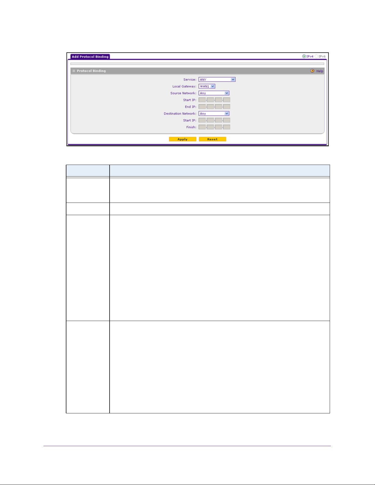
ProSAFE Dual WAN Gigabit WAN SSL VPN Firewall FVS336Gv2
8. Configure the protocol binding settings as described in the following table.
Setting Description
Service From the menu, select a service or application to be covered by this rule. If the service or
application does not appear in the list, you must define it (see Manage Customized
Services on page 280).
Local Gateway From the menu, select a WAN interface.
Source Network The source network settings determine which computers on your network are covered by
this rule. Select an option from the Source Network menu:
• Any. All devices on your LAN.
• Single Address. In the Start IP field, enter the IP address to which the rule is
applied.
• Address Range. In the Start IP field and End IP field, enter the IP addresses for the
range to which the rule is applied.
• GROUP1-GROUP8 or a group name. The rule is applied to the selected group. The
group can be a LAN group or an IP LAN group.
For information about LAN groups, see Manage IPv4 LAN Groups and Hosts on
page 132. The Destination Network menu displays only IP LAN group names that
you added. If you did not add any IP LAN groups, the menu does not display IP LAN
groups. For information about IP groups, see Manage IP Address Groups on
page 288.
Destination
Network
The destination network settings determine which Internet locations (based on their IP
addresses) are covered by the rule. Select an option from the Destination Network
menu:
• Any. All Internet IP addresses.
• Single Address. In the Start IP field, enter the IP address to which the rule is
applied.
• Address Range. In the Start IP field and End IP field, enter the IP addresses for the
range to which the rule is applied.
• Group name. The rule is applied to the selected IP WAN group.
The Destination Network menu displays only IP WAN group names that you added.
If you did not add any IP WAN groups, the menu does not display IP W AN groups. For
information about IP groups, see Manage IP Address Groups on page 288.
9. Click the Apply button.
Configure the IPv4 Internet and WAN Settings
53

ProSAFE Dual WAN Gigabit WAN SSL VPN Firewall FVS336Gv2
Your settings are saved.
The protocol binding rule is added to the Protocol Binding table. The rule is automatically
enabled, which is indicated by a green circle in the ! status icon column.
Change a Protocol Binding Rule
The following procedure describes how to change an existing protocol binding rule.
To change a protocol binding rule:
1. On your computer, launch an Internet browser.
2. In the address field of your browser, enter the IP address that was assigned to the VPN
firewall during the installation process.
The VPN firewall factory default IP address is 192.168.1.1.
The NETGEAR Configuration Manager Login screen displays.
3. In the Username field, type your user name and in the Password / Passcode field, type
your password.
For the default administrative account, the default user name is admin and the default
password is password.
4. If you changed the default domain or were assigned a domain, from the Domain menu,
select the domain.
If you did not change the domain or were not assigned a domain, leave the menu
selection at geardomain.
5. Click the Login button.
The Router Status screen displays.
6. Select Network Configuration > Protocol Binding.
The Protocol Bindings screen displays.
7. In the Protocol Bindings table, click the Edit button for the binding that you want to change.
The Edit Protocol Bindings screen displays.
8. Change the settings.
For more information about the settings, see Configure Protocol Binding Rules for IPv4
Interfaces on page 51.
9. Click the Apply button.
Your settings are saved. The modified protocol binding displays in the Protocol Bindings
table on the Protocol Bindings screen.
Manage Existing Protocol Binding Rules
The following procedure describes how to enable or disable existing protocol binding rules or
remove protocol binding rules that you no longer need.
Configure the IPv4 Internet and WAN Settings
54

ProSAFE Dual WAN Gigabit WAN SSL VPN Firewall FVS336Gv2
To enable, disable, or remove one or more protocol binding rules:
1. On your computer, launch an Internet browser.
2. In the address field of your browser, enter the IP address that was assigned to the VPN
firewall during the installation process.
The VPN firewall factory default IP address is 192.168.1.1.
The NETGEAR Configuration Manager Login screen displays.
3. In the Username field, type your user name and in the Password / Passcode field, type
your password.
For the default administrative account, the default user name is admin and the default
password is password.
4. If you changed the default domain or were assigned a domain, from the Domain menu,
select the domain.
If you did not change the domain or were not assigned a domain, leave the menu
selection at geardomain.
5. Click the Login button.
The Router Status screen displays.
6. Select Network Configuration > Protocol Binding.
The Protocol Bindings screen displays.
7. In the Protocol Bindings table, select the check box to the left of each protocol binding that
you want to enable, disable, or remove or click the Select All button to select all bindings.
8. Click one of the following buttons:
• Enable. Enables the selected protocol bindings.
The ! status icons change from gray circles to green circles, indicating that the
selected bindings are enabled. (By default, when you add a binding to the table, the
binding is automatically enabled.)
• Disable. Disables the selected protocol bindings.
The ! status icons change from green circles to gray circles, indicating that the
selected bindings are disabled.
• Delete. Removes the selected protocol bindings.
The selected bindings are removed from the Protocol Bindings table.
Configure the IPv4 Internet and WAN Settings
55

ProSAFE Dual WAN Gigabit WAN SSL VPN Firewall FVS336Gv2
Configure the Auto-Rollover Mode and Failure Detection Method for IPv4 Interfaces
Instead of using two WAN interfaces simultaneously in a load balancing configuration, you
can use one WAN interface as the primary link and the other WAN interface as the backup
link for increased reliability.
The following sections provide information about configuring auto-rollover mode and the
failure detection method for IPv4 interfaces:
• Auto-Rollover Mode and Failure Detection
• Configure Auto-Rollover Mode for IPv4 WAN Interfaces
• Configure the Failure Detection Method for IPv4 WAN Interfaces
Auto-Rollover Mode and Failure Detection
To use a redundant ISP link for backup purposes, ensure that the backup WAN interface is
configured. Then select the WAN interface that must function as the primary link for this
mode and configure the WAN failure detection method to support auto-rollover.
When the VPN firewall is configured in auto-rollover mode, it uses the selected WAN failure
detection method to detect the status of the primary link connection at regular intervals. For
IPv4 interfaces, the VPN firewall detects link failure in one of the following ways:
• By sending DNS queries to a DNS server
• By sending a ping request to an IP address
From the primary WAN interface, DNS queries or ping requests are sent to the specified IP
address. If replies are not received, after a specified number of retries, the primary WAN
interface is considered down and a rollover to the backup WAN interface occurs. When the
primary WAN interface comes back up, another rollover occurs from the backup WAN
interface back to the primary WAN interface. The WAN failure detection method that you
select applies only to the primary WAN interface, that is, it monitors the primary link only.
Configure Auto-Rollover Mode for IPv4 WAN Interfaces
The following procedure describes how to configure auto-rollover mode for IPv4 WAN
interfaces.
To configure auto-rollover mode for IPv4 WAN interfaces:
1. On your computer, launch an Internet browser.
2. In the address field of your browser, enter the IP address that was assigned to the VPN
firewall during the installation process.
The VPN firewall factory default IP address is 192.168.1.1.
The NETGEAR Configuration Manager Login screen displays.
3. In the Username field, type your user name and in the Password / Passcode field, type
your password.
Configure the IPv4 Internet and WAN Settings
56
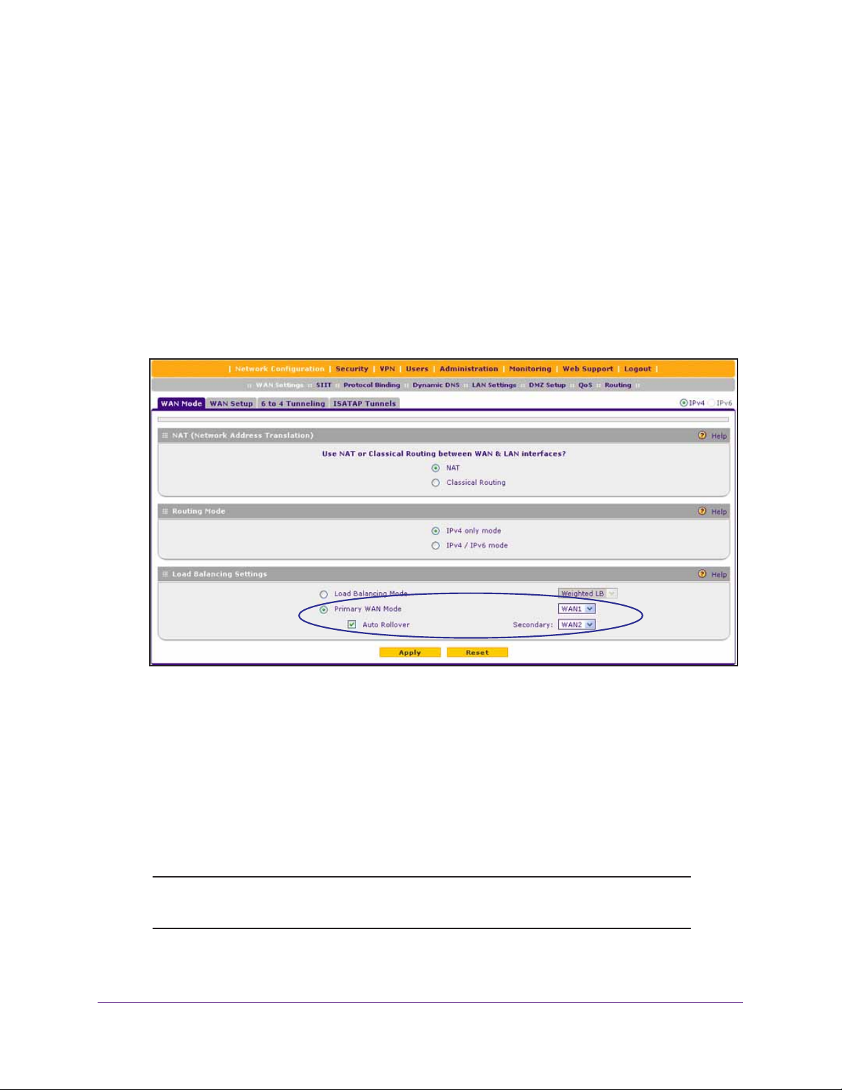
ProSAFE Dual WAN Gigabit WAN SSL VPN Firewall FVS336Gv2
For the default administrative account, the default user name is admin and the default
password is password.
4. If you changed the default domain or were assigned a domain, from the Domain menu,
select the domain.
If you did not change the domain or were not assigned a domain, leave the menu
selection at geardomain.
5. Click the Login button.
The Router Status screen displays.
6. Select Network Configuration > WAN Settings > WAN Mode.
The WAN Mode screen displays.
7. In the Load Balancing Settings section, configure the following settings:
a. Select the Primary WAN Mode radio button.
b. From the corresponding menu on the right, select a WAN interface to function as the
primary WAN interface.
The other WAN interface becomes disabled.
c. Select the Auto Rollover check box.
d. From the corresponding menu on the right, select a WAN interface to function as the
backup WAN interface.
Note: Ensure that the backup WAN interface is configured before enabling
auto-rollover mode.
8. Click the Apply button.
Configure the IPv4 Internet and WAN Settings
57

ProSAFE Dual WAN Gigabit WAN SSL VPN Firewall FVS336Gv2
Your settings are saved.
Configure the Failure Detection Method for IPv4 WAN Interfaces
The following procedure describes how to configure the failure detection method for IPv4
WAN interfaces that function in auto-rollover mode.
To configure the failure detection method for IPv4 WAN interfaces:
1. On your computer, launch an Internet browser.
2. In the address field of your browser, enter the IP address that was assigned to the VPN
firewall during the installation process.
The VPN firewall factory default IP address is 192.168.1.1.
The NETGEAR Configuration Manager Login screen displays.
3. In the Username field, type your user name and in the Password / Passcode field, type
your password.
For the default administrative account, the default user name is admin and the default
password is password.
4. If you changed the default domain or were assigned a domain, from the Domain menu,
select the domain.
If you did not change the domain or were not assigned a domain, leave the menu
selection at geardomain.
5. Click the Login button.
The Router Status screen displays.
6. Select Network Configuration > WAN Settings > WAN Setup.
The WAN Setup screen displays the IPv4 settings.
7. In the WAN IPv4 Settings table, click the Edit button for the WAN interface that you
selected as the primary WAN interface.
The WAN IPv4 ISP Settings screen displays.
8. Click the Advanced option arrow in the upper right.
The WAN Advanced Options screen displays for the WAN interface that you selected.
9. Locate the Failure Detection Method section.
10. Enter the settings as described in the following table.
Configure the IPv4 Internet and WAN Settings
58

ProSAFE Dual WAN Gigabit WAN SSL VPN Firewall FVS336Gv2
Setting Description
Failure Detection
Method
DNS Server The IP address of the DNS server.
IP Address The IP address of the interface that must receive the ping request. The interface must
Retry Interval is The retry interval in seconds. The DNS query or ping is sent after every retry interval.
Failover after The number of failover attempts. The primary WAN interface is considered down after
Select a failure detection method:
• WAN DNS. DNS queries are sent to the WAN DNS server that you configured for
the WAN interface (see
Settings on page 30).
• Custom DNS. DNS queries are sent to a DNS server that you must specify in the
DNS Server field.
• Ping. Pings are sent to a public IP address that you must specify in the IP
Address field.
Note: DNS queries or pings are sent through the WAN interface that is being
monitored. The retry interval and number of failover attempts determine how quickly
the VPN firewall switches from the primary link to the backup link if the primary link fails,
or when the primary link comes back up, switches back from the backup link to the
primary link.
not reject the ping request and must not consider ping traffic to be abusive.
The default retry interval is 30 seconds.
the specified number of queries has failed to elicit a reply. The backup interface is
brought up after this situation occurs. The failover default is 4 failures.
Configure the IPv4 Internet Connection and WAN
Note: The default time to roll over after the primary WAN interface fails is
two
minutes. The minimum test period is 30 seconds, and the
minimum number of tests is 2.
11. Click the Apply button.
Your settings are saved.
Note: You can configure the VPN firewall to generate a WAN status log and
email this log to a specified address (see
Manage Logging, Alerts,
and Event Notifications on page 567).
Manage Secondary IPv4 WAN Addresses
The following sections provide information about managing secondary IPv4 WAN addresses:
• Secondary IPv4 WAN Addresses
• Add a Secondary WAN Address to a WAN IPv4 Interface
Configure the IPv4 Internet and WAN Settings
59

ProSAFE Dual WAN Gigabit WAN SSL VPN Firewall FVS336Gv2
• Remove One or More Secondary WAN Addresses
Secondary IPv4 WAN Addresses
You can set up a single WAN Ethernet port to be accessed through multiple IPv4 addresses
by adding aliases to the port. An alias is a secondary WAN address. One advantage is, for
example, that you can assign different virtual IP addresses to a web server and an FTP
server, even though both servers use the same physical IP address. You can add several
secondary IP addresses to a single WAN port.
After you configure secondary WAN addresses, you can assign these addresses as follows
when you configure firewall rules:
• As a WAN destination IP address for a LAN WAN inbound firewall rule (see Add LAN
WAN Inbound Service Rules on page 228).
• As a WAN destination IP address for a DMZ WAN inbound firewall rule (see Add DMZ
WAN Inbound Service Rules on page 237).
• As a NAT IP address for a LAN WAN outbound firewall (see Add LAN WAN Outbound
Service Rules on page 223).
• As a NAT IP address for a DMZ WAN outbound firewall (see Add DMZ WAN Outbound
Service Rules on page 233).
For more information about firewall rules, see Overview of Rules to Block or Allow Specific
Kinds of Traffic on page 210.
Make sure that any secondary WAN addresses are different from the primary WAN, LAN,
and DMZ IP addresses that are already configured on the VPN firewall. However, primary
and secondary WAN addresses can be in the same subnet.
The following is an example of correctly configured IP addresses:
• Primary WAN1 IP address. 10.0.0.1 with subnet 255.0.0.0
• Secondary WAN1 IP address. 30.0.0.1 with subnet 255.0.0.0
• Primary WAN2 IP address. 20.0.0.1 with subnet 255.0.0.0
• Secondary WAN2 IP address. 40.0.0.1 with subnet 255.0.0.0
• DMZ IP address. 192.168.10.1 with subnet 255.255.255.0
• Primary LAN IP address. 192.168.1.1 with subnet 255.255.255.0
• Secondary LAN IP address. 192.168.20.1 with subnet 255.255.255.0
Add a Secondary WAN Address to a WAN IPv4 Interface
The following procedure describes how to add a secondary WAN address to a WAN IPv4
interface.
To add a secondary WAN address to a WAN IPv4 interface:
1. On your computer, launch an Internet browser.
Configure the IPv4 Internet and WAN Settings
60

ProSAFE Dual WAN Gigabit WAN SSL VPN Firewall FVS336Gv2
2. In the address field of your browser, enter the IP address that was assigned to the VPN
firewall during the installation process.
The VPN firewall factory default IP address is 192.168.1.1.
The NETGEAR Configuration Manager Login screen displays.
3. In the Username field, type your user name and in the Password / Passcode field, type
your password.
For the default administrative account, the default user name is admin and the default
password is password.
4. If you changed the default domain or were assigned a domain, from the Domain menu,
select the domain.
If you did not change the domain or were not assigned a domain, leave the menu
selection at geardomain.
5. Click the Login button.
The Router Status screen displays.
6. Select Network Configuration > WAN Settings > WAN Setup.
The WAN Setup screen displays the IPv4 settings.
7. In the WAN IPv4 Settings table, click the Edit button for WAN interface for which you want
to add a secondary WAN address.
The WAN IPv4 ISP Settings screen displays.
8. Click the Secondary Addresses option arrow in the upper right.
The WAN Secondary Addresses screen displays for the WAN interface that you selected.
The following figure shows the WAN2 Secondary Addresses screen as an example and
includes one entry in the List of Secondary WAN addresses table.
The List of Secondary WAN addresses table displays the secondary LAN IP addresses
added for the selected WAN interface.
9. In the Add WAN Secondary Addresses section, enter the following settings:
• IP Address. Enter the secondary address that you want to assign to the WAN port.
• Subnet Mask. Enter the subnet mask for the secondary IP address.
Configure the IPv4 Internet and WAN Settings
61

ProSAFE Dual WAN Gigabit WAN SSL VPN Firewall FVS336Gv2
10. Click the Add button.
The secondary IP address is added to the List of Secondary WAN addresses table.
11. Repeat Step 9 and Step 10 for each secondary IP address that you want to add to the List
of Secondary WAN addresses table.
Remove One or More Secondary WAN Addresses
The following procedure describes how to remove one or more secondary WAN addresses
from a WAN IPv4 interface.
To remove one or more secondary WAN addresses:
1. On your computer, launch an Internet browser.
2. In the address field of your browser, enter the IP address that was assigned to the VPN
firewall during the installation process.
The VPN firewall factory default IP address is 192.168.1.1.
The NETGEAR Configuration Manager Login screen displays.
3. In the Username field, type your user name and in the Password / Passcode field, type
your password.
For the default administrative account, the default user name is admin and the default
password is password.
4. If you changed the default domain or were assigned a domain, from the Domain menu,
select the domain.
If you did not change the domain or were not assigned a domain, leave the menu
selection at geardomain.
5. Click the Login button.
The Router Status screen displays.
6. Select Network Configuration > WAN Settings > WAN Setup.
The WAN Setup screen displays the IPv4 settings.
7. In the WAN IPv4 Settings table, click the Edit button for the WAN interface for which you
want to remove one or more secondary WAN addresses.
The WAN IPv4 ISP Settings screen displays.
8. Click the Secondary Addresses option arrow in the upper right.
The WAN Secondary Addresses screen displays for the WAN interface that you selected.
9. In the List of Secondary WAN addresses table, select the check box to the left of the
address that you want to remove or click the Select All button to select all addresses.
10. Click the Delete button.
The selected addresses are removed from the List of Secondary WAN addresses table.
Configure the IPv4 Internet and WAN Settings
62

ProSAFE Dual WAN Gigabit WAN SSL VPN Firewall FVS336Gv2
Manage Dynamic DNS Connections
The following sections provide information about managing Dynamic DNS:
• Dynamic DNS
• Configure Dynamic DNS
Dynamic DNS
Dynamic DNS (DDNS) is an Internet service that allows devices with varying public IPv4
addresses to be located using Internet domain names. To use DDNS, you must set up an
account with a DDNS provider such as DynDNS.org, TZO.com, Oray.net, or 3322.org. (The
web management interface of the VPN firewall provides links to these DDNS providers.) The
VPN firewall firmware includes software that notifies DDNS servers of changes in the WAN
IP address so that the services running on this network can be accessed by others on the
Internet.
If your network has a permanently assigned IP address, you can register a domain name and
have that name linked with your IP address by public Domain Name Servers (DNS).
However, if your Internet account uses a dynamically assigned IP address, you do not know
in advance what your IP address will be, and the address can change frequently—hence, the
need for a commercial DDNS service, which allows you to register an extension to its domain
and restores DNS requests for the resulting fully qualified domain name (FQDN) to your
frequently changing IP address.
After you configure your account information on the VPN firewall, when your ISP-assigned IP
address changes, your VPN firewall automatically contacts your DDNS service provider, logs
in to your account, and registers your new IP address. Consider the following:
• For auto-rollover mode, you need a fully qualified domain name (FQDN) to implement
features such as exposed hosts and virtual private networks regardless of whether you
have a fixed or dynamic IP address.
• For load balancing mode, you might still need a fully qualified domain name (FQDN)
either for convenience or if you have a dynamic IP address.
Note: If your ISP assigns a private WAN IP address such as 192.168.x.x or
10.x.x.x, the DDNS service does not work because private addresses
are not routed on the Internet.
Configure Dynamic DNS
The following procedure describes how to configure dynamic DNS (DDNS) for both WAN
interfaces.
Configure the IPv4 Internet and WAN Settings
63

ProSAFE Dual WAN Gigabit WAN SSL VPN Firewall FVS336Gv2
To configure DDNS for both WAN interfaces:
1. On your computer, launch an Internet browser.
2. In the address field of your browser, enter the IP address that was assigned to the VPN
firewall during the installation process.
The VPN firewall factory default IP address is 192.168.1.1.
The NETGEAR Configuration Manager Login screen displays.
3. In the Username field, type your user name and in the Password / Passcode field, type
your password.
For the default administrative account, the default user name is admin and the default
password is password.
4. If you changed the default domain or were assigned a domain, from the Domain menu,
select the domain.
If you did not change the domain or were not assigned a domain, leave the menu
selection at geardomain.
5. Click the Login button.
The Router Status screen displays.
6. Select Network Configuration > Dynamic DNS.
The DNS submenu tabs display, with the Dynamic DNS screen in view.
Configure the IPv4 Internet and WAN Settings
64
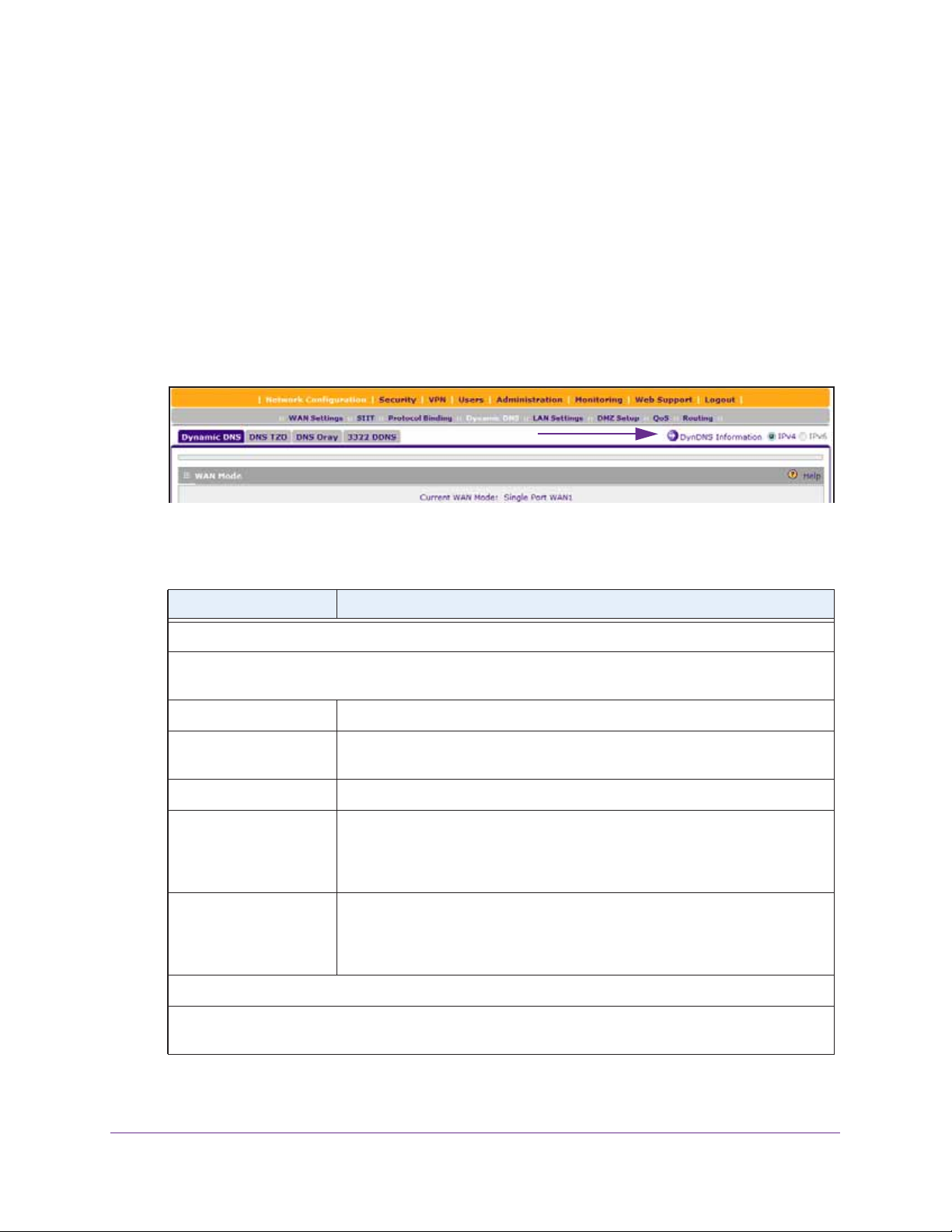
ProSAFE Dual WAN Gigabit WAN SSL VPN Firewall FVS336Gv2
The WAN Mode section reports the configured WAN mode (for example, Single Port
WAN1, Load Balancing, or Auto Rollover). Only those options that match the configured
WAN mode are accessible on the screen.
7. Click the submenu tab for your DDNS service provider:
• Dynamic DNS for DynDNS.org (which is shown in the following figure)
• DNS TZO for TZO.com
• DNS Oray for Oray.net
• 3322 DDNS for 3322.org
8. Click the Information option arrow in the upper right of a DNS screen for registration
information (for example, DynDNS Information).
9. Visit the website of the DDNS service provider and register for an account (for example, for
DynDNS.org, visit
http://www.dyndns.com/).
10. Configure the DDNS service settings as described in the following table.
Setting Description
WAN1 (... Status: ...)
Select the Yes radio button to enable the DDNS service. The fields that display depend on the DDNS
service provider that you have selected.
Host and Domain Name The host and domain name for the DDNS service.
Username or
User Email Address
Password or User Key The password that is used for DDNS server authentication.
Use wildcards If your DDNS provider allows the use of wildcards in resolving your URL, you
Update every 30 days If your WAN IP address does not often change, you might need to force a
The user name or email address for DDNS server authentication.
can select the Use wildcards check box to activate this feature. For example,
the wildcard feature causes *.yourhost.dyndns.org to be aliased to the same IP
address as yourhost.dyndns.org.
periodic update to the DDNS service to prevent your account from expiring. If
the Update every 30 days check box displays, select it to enable a periodic
update.
WAN2 (... Status: ...)
See the information for WAN1 in this table about how to enter the settings. You can select different DDNS
services for different WAN interfaces.
11. Click the Apply button.
Configure the IPv4 Internet and WAN Settings
65

ProSAFE Dual WAN Gigabit WAN SSL VPN Firewall FVS336Gv2
Your settings are saved.
Managing Advanced WAN Options
The following sections provide information about managing advanced WAN options:
• Change the Maximum Transmission Unit Size
• Change the Port Speed and Duplex Settings
• Change the Advertised MAC Address of the VPN Firewall
• Set the WAN Connection Type and Corresponding Speeds
Note: For information about another advanced WAN option, the failure
detection for auto-rollover mode for IPv4 interfaces, see
Failure Detection Method for IPv4 WAN Interfaces on page 58.
Configure the
Change the Maximum Transmission Unit Size
Change the maximum transmit unit (MTU) size only if you have reason to do so or your ISP
requests that you do so.
To change the MTU size:
1. On your computer, launch an Internet browser.
2. In the address field of your browser, enter the IP address that was assigned to the VPN
firewall during the installation process.
The VPN firewall factory default IP address is 192.168.1.1.
The NETGEAR Configuration Manager Login screen displays.
3. In the Username field, type your user name and in the Password / Passcode field, type
your password.
For the default administrative account, the default user name is admin and the default
password is password.
4. If you changed the default domain or were assigned a domain, from the Domain menu,
select the domain.
If you did not change the domain or were not assigned a domain, leave the menu
selection at geardomain.
5. Click the Login button.
The Router Status screen displays.
6. Select Network Configuration > WAN Settings > WAN Setup.
The WAN Setup screen displays the IPv4 settings.
Configure the IPv4 Internet and WAN Settings
66

ProSAFE Dual WAN Gigabit WAN SSL VPN Firewall FVS336Gv2
7. In the WAN IPv4 Settings table, click the Edit button for the WAN interface that you want to
configure.
The WAN IPv4 ISP Settings screen displays.
8. Click the Advanced option arrow in the upper right.
The WAN Advanced Options screen displays for the WAN interface that you selected.
The following figure shows the WAN2 Advanced Options screen as an example.
9. In the MTU Size section, configure the MTU size:
• Default. Select this radio button for the normal maximum transmit unit (MTU) size.
For most Ethernet networks, this value is 1500 bytes, or 1492
bytes for PPPoE
connections.
• Custom. Select this radio button and enter an MTU value in the Bytes field. For
some ISPs, you might need to reduce the MTU, but this is rarely required. Do not
change the MTU unless you are sure that it is necessary for your ISP connection.
WARNING:
Depending on the changes that you make, when you click the Apply
button, the VPN firewall might restart or services such as HTTP and
SMTP might restart.
10. Click the Apply button.
Your settings are saved.
Configure the IPv4 Internet and WAN Settings
67

ProSAFE Dual WAN Gigabit WAN SSL VPN Firewall FVS336Gv2
Change the Port Speed and Duplex Settings
In most cases, the VPN firewall can automatically determine the connection speed of the
WAN port of the device (modem, dish, or router) that provides the WAN connection. If you
cannot establish an Internet connection, you might need to manually select the port speed.
To change the port speed and duplex settings:
1. On your computer, launch an Internet browser.
2. In the address field of your browser, enter the IP address that was assigned to the VPN
firewall during the installation process.
The VPN firewall factory default IP address is 192.168.1.1.
The NETGEAR Configuration Manager Login screen displays.
3. In the Username field, type your user name and in the Password / Passcode field, type
your password.
For the default administrative account, the default user name is admin and the default
password is password.
4. If you changed the default domain or were assigned a domain, from the Domain menu,
select the domain.
If you did not change the domain or were not assigned a domain, leave the menu
selection at geardomain.
5. Click the Login button.
The Router Status screen displays.
6. Select Network Configuration > WAN Settings > WAN Setup.
The WAN Setup screen displays the IPv4 settings.
7. In the WAN IPv4 Settings table, click the Edit button for the WAN interface that you want to
configure.
The WAN IPv4 ISP Settings screen displays.
8. Click the Advanced option arrow in the upper right.
The WAN Advanced Options screen displays for the WAN interface that you selected.
The following figure shows the WAN2 Advanced Options screen as an example.
Configure the IPv4 Internet and WAN Settings
68

ProSAFE Dual WAN Gigabit WAN SSL VPN Firewall FVS336Gv2
9. In the Speed section, if you know the Ethernet port speed of the modem, dish, or router,
select it from the Port Speed menu.
• AutoSense. Speed autosensing. This is the default setting. The firewall can sense all
Ethernet speeds and duplex modes, including 1000BASE-T speed at full duplex.
• 10BaseT Half_Duplex. Ethernet speed at half duplex. Use the half-duplex settings
only if the full-duplex settings do not function correctly.
• 10BaseT Full_Duplex. Ethernet speed at full duplex.
• 100BaseT Half_Duplex. Fast Ethernet speed at half duplex. Use the half-duplex
settings only if the full-duplex settings do not function correctly.
• 100BaseT Full_Duplex. Fast Ethernet speed at full duplex.
• 1000BaseT Full_Duplex. Gigabit Ethernet speed at full duplex.
WARNING:
Depending on the changes that you made, when you click the Apply
button, the VPN firewall might restart, or services such as HTTP
and SMTP might restart.
10. Click the Apply button.
Your settings are saved.
Configure the IPv4 Internet and WAN Settings
69

ProSAFE Dual WAN Gigabit WAN SSL VPN Firewall FVS336Gv2
Change the Advertised MAC Address of the VPN Firewall
Each computer or router on your network has a unique 48-bit local Ethernet address. This is
also referred to as the computer’s Media Access Control (MAC) address.
If your ISP has MAC authentication enabled, you cannot establish a connection with your ISP
if the VPN firewall is not configured with the correct MAC address. If your ISP requires MAC
authentication and another MAC address was previously registered with your ISP, you must
configure that MAC address on the VPN firewall.
To configure advanced WAN options:
1. On your computer, launch an Internet browser.
2. In the address field of your browser, enter the IP address that was assigned to the VPN
firewall during the installation process.
The VPN firewall factory default IP address is 192.168.1.1.
The NETGEAR Configuration Manager Login screen displays.
3. In the Username field, type your user name and in the Password / Passcode field, type
your password.
For the default administrative account, the default user name is admin and the default
password is password.
4. If you changed the default domain or were assigned a domain, from the Domain menu,
select the domain.
If you did not change the domain or were not assigned a domain, leave the menu
selection at geardomain.
5. Click the Login button.
The Router Status screen displays.
6. Select Network Configuration > WAN Settings > WAN Setup.
The WAN Setup screen displays the IPv4 settings.
7. In the WAN IPv4 Settings table, click the Edit button for the WAN interface that you want to
configure.
The WAN IPv4 ISP Settings screen displays.
8. Click the Advanced option arrow in the upper right.
The WAN Advanced Options screen displays for the WAN interface that you selected.
The following figure shows the WAN2 Advanced Options screen as an example.
Configure the IPv4 Internet and WAN Settings
70

ProSAFE Dual WAN Gigabit WAN SSL VPN Firewall FVS336Gv2
9. In the Router’s MAC Address section, enter the settings as described in the following table.
Setting Description
Use Default Address To use the VPN firewall’s own MAC address, select the Use Default Address
radio button. This is the default setting.
Use this computer’s MAC
Address
Use this MAC Address Select the Use this MAC Address radio button and manually enter the MAC
Select the Use this computer’s MAC Address radio button to allow the VPN
firewall to use the MAC address of the computer you are now using to access
the web management interface. This setting is useful if your ISP requires MAC
authentication.
address in the field next to the radio button. You would typically enter the MAC
address that your ISP requires for MAC authentication.
Note: The format for the MAC address is 01:23:45:67:89:AB (numbers
0–9 and either uppercase or lowercase letters A–F). If you enter a MAC address,
the existing entry is overwritten.
WARNING:
Depending on the changes that you made, when you click the Apply
button, the VPN firewall might restart or services such as HTTP and
SMTP might restart.
10. Click the Apply button.
Configure the IPv4 Internet and WAN Settings
71

ProSAFE Dual WAN Gigabit WAN SSL VPN Firewall FVS336Gv2
Your settings are saved.
Set the WAN Connection Type and Corresponding Speeds
The WAN connection type and corresponding upload and download connection speeds in
effect limit the rate of traffic that is being forwarded by the VPN firewall.
To set the WAN connection type and upload and download connection speeds:
1. On your computer, launch an Internet browser.
2. In the address field of your browser, enter the IP address that was assigned to the VPN
firewall during the installation process.
The VPN firewall factory default IP address is 192.168.1.1.
The NETGEAR Configuration Manager Login screen displays.
3. In the Username field, type your user name and in the Password / Passcode field, type
your password.
For the default administrative account, the default user name is admin and the default
password is password.
4. If you changed the default domain or were assigned a domain, from the Domain menu,
select the domain.
If you did not change the domain or were not assigned a domain, leave the menu
selection at geardomain.
5. Click the Login button.
The Router Status screen displays.
6. Select Network Configuration > WAN Settings > WAN Setup.
The WAN Setup screen displays the IPv4 settings.
7. In the WAN IPv4 Settings table, click the Edit button for the WAN interface that you want to
configure.
The WAN IPv4 ISP Settings screen displays.
8. Click the Advanced option arrow in the upper right.
The WAN Advanced Options screen displays for the WAN interface that you selected.
The following figure shows the WAN2 Advanced Options screen as an example.
Configure the IPv4 Internet and WAN Settings
72
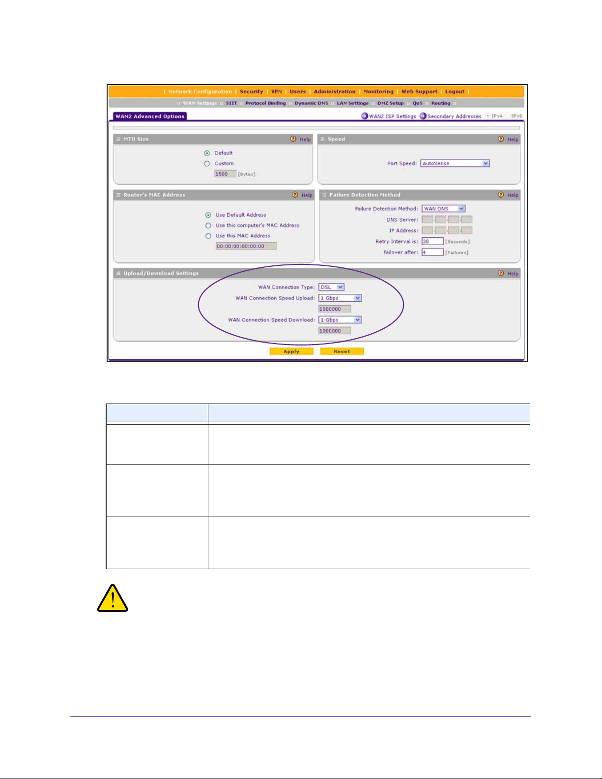
ProSAFE Dual WAN Gigabit WAN SSL VPN Firewall FVS336Gv2
9. In the Upload/Download Settings section, enter the settings as described in the following
table.
Setting Description
WAN Connection Type From the menu, select the type of connection that the VPN firewall uses to
connect to the Internet over the selected interface:
DSL, ADLS, T1, T3, or Other.
WAN Connection Speed
Upload
WAN Connection Speed
Download
From the menu, select the maximum upload speed that your ISP provides for the
selected interface. You can select from 56 Kbps to 1 Gbps, or you can select
Custom and enter the speed in Kbps in the field below the WAN Connection
Speed Upload menu.
From the menu, select the maximum download speed that your ISP provides for
the selected interface. You can select from 56 Kbps to 1 Gbps, or you can select
Custom and enter the speed in Kbps in the field below the WAN Connection
Speed Download menu.
WARNING:
Depending on the changes that you made, when you click the Apply
button, the VPN firewall might restart or services such as HTTP and
SMTP might restart.
10. Click the Apply button.
Your settings are saved.
Configure the IPv4 Internet and WAN Settings
73

ProSAFE Dual WAN Gigabit WAN SSL VPN Firewall FVS336Gv2
Manage WAN QoS and WAN QoS Profiles
The following sections provide information about managing WAN Quality of Service (QoS)
and WAN QoS profiles:
• WAN QoS
• Add a Rate Control WAN QoS Profile
• Add a Priority Queue WAN QoS Profile
• Enable WAN QoS and Select the WAN QoS Type
• Change a QoS Profile
• Enable, Disable, or Remove One or More WAN QoS Profiles
WAN QoS
The VPN firewall can support multiple Quality of Service (QoS) profiles for each WAN
interface.
You can assign profiles to services such as HTTP, FTP, and DNS and to LAN groups or IP
addresses. Profiles enforce either rate control with bandwidth allocation or priority queue
control. You can configure both types of profiles, but either all profiles on the VPN firewall
enforce rate control and the profiles that you configured for priority queue control are inactive,
or the other way around. Both types of profiles cannot be active simultaneously.
• Rate control with bandwidth allocation. These types of profiles specify how bandwidth
is distributed among the services and hosts. A profile with a high priority is of fered excess
bandwidth while the required bandwidth is still allocated to profiles that specify minimum
and maximum bandwidth rates. The congestion priority represents the classification level
of the packets among the priority queues within the system. If you select a default
congestion priority, traffic is mapped based on the Type of Service (ToS) field in the
packet’s IP header.
• Priority queue control. These types of profiles specify the priority levels of the services.
You can select a high-priority queue or a low-priority queue. Services in the high-priority
queue share 60 percent of the interface bandwidth; services in the low-priority queue
share 10 percent of the interface bandwidth. By default, all services are assigned the
medium-priority queue in which they share 30 percent of the interface bandwidth.
Both types of profiles let you allocate the Differentiated Services (DiffServ) QoS packet
matching and QoS packet marking settings, which you configure by specifying Differentiated
Services Code Point (DSCP) values, from 0 to 63.
Note: Before you enable WAN QoS, make sure that the WAN connection
type and speeds are configured correctly (see
WAN Options on page 66).
Configure the IPv4 Internet and WAN Settings
74
Managing Advanced

ProSAFE Dual WAN Gigabit WAN SSL VPN Firewall FVS336Gv2
Note: To configure and apply QoS profiles successfully, familiarity with QoS
concepts such QoS priority queues, IP precedence, DHCP, and their
values is helpful.
Add a Rate Control WAN QoS Profile
The following procedure describes how to add a rate control QoS profile for a WAN interface.
To add a rate control WAN QoS profile:
1. On your computer, launch an Internet browser.
2. In the address field of your browser, enter the IP address that was assigned to the VPN
firewall during the installation process.
The VPN firewall factory default IP address is 192.168.1.1.
The NETGEAR Configuration Manager Login screen displays.
3. In the Username field, type your user name and in the Password / Passcode field, type
your password.
For the default administrative account, the default user name is admin and the default
password is password.
4. If you changed the default domain or were assigned a domain, from the Domain menu,
select the domain.
If you did not change the domain or were not assigned a domain, leave the menu
selection at geardomain.
5. Click the Login button.
The Router Status screen displays.
6. Select Network Configuration > QoS.
The QoS screen displays.
7. Under the List of QoS Profiles table, click the Add button.
The Add QoS screen displays. The following figure shows settings for a rate control QoS
profile.
Configure the IPv4 Internet and WAN Settings
75

ProSAFE Dual WAN Gigabit WAN SSL VPN Firewall FVS336Gv2
8. Enter the settings as described in the following table.
Setting Description
QoS Type From the menu, select Rate Control.
For information about the Priority selection, see Add a Priority Queue WAN
QoS Profile on page 78.
Interface From the menu, select a WAN interface.
Service From the menu, select a service or application to be covered by this profile. If
the service or application does not appear in the list, you must define it (see
Manage Customized Services on page 280).
Direction From the menu, select the direction to which rate control is applied:
• Inbound Traffic. Rate control is applied to inbound traffic only.
• Outbound Traffic. Rate control is applied to outbound traffic only.
• Both. Rate control is applied to both outbound and inbound traffic.
Diffserv QoS Match Enter a DSCP value in the range of 0 through 63. Packets are classified against
this value. Leave this field blank to disable packet matching.
Configure the IPv4 Internet and WAN Settings
76

ProSAFE Dual WAN Gigabit WAN SSL VPN Firewall FVS336Gv2
Setting Description
Congestion Priority From the menu, select the priority queue that determines the allocation of
excess bandwidth and the classification level of the packets among other
priority queues on the VPN firewall:
• Default. Traffic is mapped based on the ToS field in the packet’s IP header.
• High. This queue includes the following DSCP values: AF41, AF42, AF43,
AF44, and CS4.
• Medium-high. This queue includes the following DSCP values: AF31,
AF32, AF33, AF34, and CS3.
• Medium. This queue includes the following DSCP values: AF21, AF22,
AF23, AF24, and CS2.
• Low. This queue includes the following DSCP values: AF11, AF12, AF13,
AF14, CS1, 0, and all other values.
Hosts From the menu, select the IP address, range of IP addresses, or group to which
the profile is applied, and, if applicable, specify how the bandwidth is allocated:
• Single IP Address. The profile is applied to a single IP address. Enter the
address in the Start IP field.
• IP Address Range. The profile is applied to an IP address range. Enter the
first address of the range in the Start IP field and the last address of the
range in the End IP field. From the Bandwidth Allocation menu, select
how the bandwidth is allocated:
- Shared. The bandwidth is shared among all IP addresses the range.
- Individual. The bandwidth is allocated to each IP address in the range.
• Group. The profile is applied to a LAN group. From the Select Group
menu, select the LAN group to which the profile is applied. For information
about LAN groups, see
From the Bandwidth Allocation menu, select how the bandwidth is
allocated:
- Shared. The bandwidth is shared among all members of a group.
- Individual. The bandwidth is allocated to each member of a group.
Manage IPv4 LAN Groups and Hosts on page 132.
Outbound Minimum
Bandwidth
Outbound Maximum
Bandwidth
Inbound Minimum
Bandwidth
Inbound Maximum
Bandwidth
Diffserv QoS Remark Enter a DSCP value in the range of 0 through 63. Packets are marked with this
Enter the minimum outbound bandwidth in Kbps that is allocated to the host.
Enter the maximum outbound bandwidth in Kbps that is allocated to the host.
Enter the minimum inbound bandwidth in Kbps that is allocated to the host.
Enter the maximum inbound bandwidth in Kbps that is allocated to the host.
value. Leave this field blank to disable packet marking.
9. Click the Apply button.
Your settings are saved. The profile is added to the List of QoS Profiles table on the QoS
screen.
You are now ready to enable WAN QoS and select the rate control QoS type (see Enable
WAN QoS and Select the WAN QoS Type on page 80).
Configure the IPv4 Internet and WAN Settings
77

ProSAFE Dual WAN Gigabit WAN SSL VPN Firewall FVS336Gv2
Add a Priority Queue WAN QoS Profile
The following procedure describes how to add a priority queue QoS profile for a WAN
interface.
To add a priority queue WAN QoS profile:
1. On your computer, launch an Internet browser.
2. In the address field of your browser, enter the IP address that was assigned to the VPN
firewall during the installation process.
The VPN firewall factory default IP address is 192.168.1.1.
The NETGEAR Configuration Manager Login screen displays.
3. In the Username field, type your user name and in the Password / Passcode field, type
your password.
For the default administrative account, the default user name is admin and the default
password is password.
4. If you changed the default domain or were assigned a domain, from the Domain menu,
select the domain.
If you did not change the domain or were not assigned a domain, leave the menu
selection at geardomain.
5. Click the Login button.
The Router Status screen displays.
6. Select Network Configuration > QoS.
The QoS screen displays.
7. Under the List of QoS Profiles table, click the Add button.
The Add QoS screen displays. The following figure shows settings for a priority QoS
profile.
Configure the IPv4 Internet and WAN Settings
78

ProSAFE Dual WAN Gigabit WAN SSL VPN Firewall FVS336Gv2
8. Enter the settings as described in the following table.
Setting Description
QoS Type From the menu, select Priority.
For information about the Rate Control selection, see Add a Rate Control WAN
QoS Profile on page 75).
Interface From the menu, select a WAN interface.
Service From the menu, select a service or application to be covered by this profile. If
the service or application does not appear in the list, you must define it (see
Manage Customized Services on page 280).
Direction From the menu, select the direction to which the priority queue is applied:
• Outbound Traffic. The priority queue is applied to outbound traffic only.
• Inbound Traffic. The priority queue is applied to inbound traffic only.
Diffserv QoS Match Enter a DSCP value in the range of 0 through 63. Packets are classified against
this value. Leave this field blank to disable packet matching.
Priority From the menu, select the priority queue that determines the allocation of
bandwidth:
• Low. All services that are assigned a low-priority queue share 10 percent of
interface bandwidth.
• High. All services that are assigned a high-priority queue share 60 percent
of interface bandwidth.
Note: By default, all services are assigned the medium-priority queue, in which
they share 30 percent of the interface bandwidth.
Configure the IPv4 Internet and WAN Settings
79

ProSAFE Dual WAN Gigabit WAN SSL VPN Firewall FVS336Gv2
Setting Description
Hosts
Start IP
End IP
Select Group
Bandwidth Allocation
Outbound Minimum
Bandwidth
Outbound Maximum
Bandwidth
Inbound Minimum
Bandwidth
Inbound Maximum
Bandwidth
Diffserv QoS Remark Enter a DSCP value in the range of 0 through 63. Packets are marked with this
These settings do not apply to a priority profile.
value. Leave this field blank to disable packet marking.
9. Click the Apply button.
Your settings are saved. The profile is added to the List of QoS Profiles table on the QoS
screen.
You are now ready to enable WAN QoS and select the priority QoS type (see Enable
WAN QoS and Select the WAN QoS Type on page 80).
Enable WAN QoS and Select the WAN QoS Type
Depending on the type of WAN QoS that you want to select, first configure one or more rate
control QoS profiles (see
QoS profiles (see Add a Priority Queue WAN QoS Profile on page 78) before you enable
WAN QoS and select the type of WAN QoS.
Add a Rate Control WAN QoS Profile on page 75) or priority control
Note: When you enable WAN QoS, the performance of the VPN firewall
might be affected slightly.
To enable WAN QoS and select the type of WAN QoS:
1. On your computer, launch an Internet browser.
2. In the address field of your browser, enter the IP address that was assigned to the VPN
firewall during the installation process.
The VPN firewall factory default IP address is 192.168.1.1.
Configure the IPv4 Internet and WAN Settings
80

ProSAFE Dual WAN Gigabit WAN SSL VPN Firewall FVS336Gv2
The NETGEAR Configuration Manager Login screen displays.
3. In the Username field, type your user name and in the Password / Passcode field, type
your password.
For the default administrative account, the default user name is admin and the default
password is password.
4. If you changed the default domain or were assigned a domain, from the Domain menu,
select the domain.
If you did not change the domain or were not assigned a domain, leave the menu
selection at geardomain.
5. Click the Login button.
The Router Status screen displays.
6. Select Network Configuration > QoS.
The QoS screen displays. The following figure shows some profiles in the List of QoS
Profiles table.
7. To enable QoS, select the Yes radio button.
By default, the No radio button is selected.
8. Specify the profile type that must be active.
• Rate control. All rate control QoS profiles that you configure are active, but priority
QoS profiles are not.
• Priority. All priority QoS profiles that you configure are active, but rate control QoS
profiles are not.
9. Click the Apply button.
Your settings are saved.
The List of QoS Profiles table shows the following columns:
Configure the IPv4 Internet and WAN Settings
81

ProSAFE Dual WAN Gigabit WAN SSL VPN Firewall FVS336Gv2
• QoS Type. The type of profile, either Rate Control or Priority.
• Interface Name. The WAN interface to which the profile applies (WAN1 or WAN2).
• Service. The service to which the profile applies.
• Direction. The WAN direction to which the profile applies (inbound, outbound, or
both).
• Rate. The bandwidth rate in Kbps or the priority.
• Hosts. The IP address, IP addresses, or group to which the rate control profile
applies. (The information in this column does not apply to priority profiles.)
• Action. The Edit button provides access to the Edit QoS screen for the
corresponding profile.
For more information about the information that is shown in the List of QoS Profiles table,
see
Add a Rate Control WAN QoS Profile on page 75 and Add a Priority Queue WAN
QoS Profile on page 78.
Change a QoS Profile
The following procedure describes how to change an existing WAN QoS profile.
To change a QoS profile:
1. On your computer, launch an Internet browser.
2. In the address field of your browser, enter the IP address that was assigned to the VPN
firewall during the installation process.
The VPN firewall factory default IP address is 192.168.1.1.
The NETGEAR Configuration Manager Login screen displays.
3. In the Username field, type your user name and in the Password / Passcode field, type
your password.
For the default administrative account, the default user name is admin and the default
password is password.
4. If you changed the default domain or were assigned a domain, from the Domain menu,
select the domain.
If you did not change the domain or were not assigned a domain, leave the menu
selection at geardomain.
5. Click the Login button.
The Router Status screen displays.
6. Select Network Configuration > QoS.
The QoS screen displays.
7. In the List of QoS Profiles table, click the Edit button for the profile that you want to change.
The Edit QoS screen displays.
Configure the IPv4 Internet and WAN Settings
82

ProSAFE Dual WAN Gigabit WAN SSL VPN Firewall FVS336Gv2
8. Change the settings.
For information about the settings, see Add a Rate Control WAN QoS Profile on page 75
and Add a Priority Queue WAN QoS Profile on page 78.
9. Click the Apply button.
Your settings are saved. The modified QoS profile displays in the List of QoS Profiles table
on the QoS screen.
Enable, Disable, or Remove One or More WAN QoS Profiles
The following procedure describes how to enable or disable existing WAN QoS profiles or
remove WAN QoS profiles that you no longer need.
To enable, disable, or remove one or more WAN QoS profiles:
1. On your computer, launch an Internet browser.
2. In the address field of your browser, enter the IP address that was assigned to the VPN
firewall during the installation process.
The VPN firewall factory default IP address is 192.168.1.1.
The NETGEAR Configuration Manager Login screen displays.
3. In the Username field, type your user name and in the Password / Passcode field, type
your password.
For the default administrative account, the default user name is admin and the default
password is password.
4. If you changed the default domain or were assigned a domain, from the Domain menu,
select the domain.
If you did not change the domain or were not assigned a domain, leave the menu
selection at geardomain.
5. Click the Login button.
The Router Status screen displays.
6. Select Network Configuration > QoS.
The QoS screen displays.
7. In the List of QoS Profiles table, select the check box to the left of each QoS profile that you
want to remove or click the Select All button to select all profiles.
8. Click one of the following buttons:
• Enable. Enables the selected WAN QoS profiles.
The ! status icons change from gray circles to green circles, indicating that the
selected profiles are enabled. (By default, when you add a profile, the profile is
automatically enabled.)
• Disable. Disables the selected WAN QoS profiles.
Configure the IPv4 Internet and WAN Settings
83

ProSAFE Dual WAN Gigabit WAN SSL VPN Firewall FVS336Gv2
The ! status icons change from green circles to gray circles, indicating that the
selected profiles are disabled.
• Delete. Removes the selected WAN QoS profiles.
The selected profiles are removed from the List of QoS Profiles table.
Additional WAN-Related Configuration Tasks
If you want the ability to manage the VPN firewall remotely , enable remote management (see
Set Up Remote Management Access on page 534). If you enable remote management,
NETGEAR strongly recommends that you change your password (see Change Passwords
and Automatic Logout Period on page 511).
As an option, you can also set up the traffic meter for each WAN interface (see Configure and
Enable the WAN IPv4 Traffic Meter on page 558).
Test the VPN firewall before deploying it in a live production environment. Verify that network
traffic can pass through the VPN firewall by doing the following:
• Ping an Internet URL.
• Ping the IP address of a device on either side of the VPN firewall.
What to Do Next
After you complete setting up the WAN connection for the VPN firewall, you might want to
address the important tasks described in the following chapters and sections before you
deploy the VPN firewall in your network:
• Chapter 3, Configure the IPv6 Internet and WAN Settings
• Chapter 4, Configure the IPv4 LAN Settings
• Configure Authentication Domains, Groups, and User Accounts on page 488
• Manage Digital Certificates for VPN Connections on page 512
• Use the IPSec VPN Wizard for Client and Gateway Configurations on page 334
• Chapter 9, Set Up Virtual Private Networking with SSL Connections
Configure the IPv4 Internet and WAN Settings
84

3. Configure the IPv6 Internet and
WAN Settings
This chapter explains how to configure the IPv6 Internet and WAN settings. The chapter
contains the following sections:
• Roadmap to Setting Up an IPv6 Internet Connection to Your ISP
• Configure the IPv6 Internet Connection and WAN Settings
• Manage Tunneling for IPv6 Traffic
• Configure Stateless IP/ICMP Translation
• Configure Auto-Rollover for IPv6 Interfaces
• Additional WAN-Related Configuration Tasks
• What to Do Next
3
85

ProSAFE Dual WAN Gigabit WAN SSL VPN Firewall FVS336Gv2
Roadmap to Setting Up an IPv6 Internet Connection to Your ISP
Typically, the VPN firewall is installed as a network gateway to function as a combined LAN
switch and firewall to protect the network from incoming threats and provide secure
connections. To complement the firewall protection, NETGEAR recommends that you use a
gateway security appliance such as a NETGEAR ProSECURE STM appliance.
The tasks that are required to complete the Internet connection of your VPN firewall depend
on whether you use an IPv4 connection, an IPv6 connection, or both to connect to your
Internet service provider (ISP). For information about setting up an IPv4 connection, see
Chapter 2, Configure the IPv4 Internet and WAN Settings.
Note: The VPN firewall supports simultaneous IPv4 and IPv6 connections.
You can configure only one WAN interface for IPv6. You can
configure the other WAN interface for IPv4.
Setting up an IPv6 Internet connection to your ISP includes six tasks, four of which are
optional.
Complete these tasks:
1. Configure the IPv6 routing mode. Configure the VPN firewall to support both devices
with IPv4 addresses and devices with IPv6 addresses.
This task is described in Manage the IPv6 Routing Mode on page 88.
2. Configure the IPv6 Internet connection to your ISP. Connect to an ISP by configuring a
WAN interface.
You have three configuration options. These tasks are described in the following
sections:
• Use a DHCPv6 Server to Configure an IPv6 Internet Connection Automatically on
page 90
• Manually Configure a Static IPv6 Internet Connection on page 94
• Manually Configure a PPPoE IPv6 Internet Connection on page 97
3. (Optional) Configure the IPv6 tunnels. Enable 6to4 tunnels and configure ISATAP
tunnels.
These tasks are described in the following sections:
• Manage 6to4 Automatic Tunneling on page 101
• Manage ISATAP Automatic Tunneling on page 103
4. (Optional) Configure Stateless IP/ICMP Translation (SIIT). Enable IPv6 devices that do
not have permanently assigned IPv4 addresses to communicate with IPv4-only devices.
This task is described in Configure Stateless IP/ICMP Translation on page 108.
Configure the IPv6 Internet and WAN Settings
86

ProSAFE Dual WAN Gigabit WAN SSL VPN Firewall FVS336Gv2
5. (Optional) Configure auto-rollover and failure detection. By default, the WAN interfaces
are configured for primary (single) WAN mode. You can enable auto-rollover and configure
the failure detection settings.
These tasks are described in Configure Auto-Rollover for IPv6 Interfaces on page 109.
6. (Optional) Configure advanced WAN options. If necessary, change the factory default
MTU size, port speed and duplex settings, advertised MAC address of the VPN firewall, and
WAN connection type and corresponding upload and download connection speeds. These
are advanced features, and you usually do not need to change the settings.
These tasks are described in Managing Advanced WAN Options on page 66 in
Chapter 2.
Configure the IPv6 Internet Connection and WAN Settings
The following sections provide information about configuring the IPv6 Internet connection
and WAN settings:
• IPv6 Network
• Manage the IPv6 Routing Mode
• Use a DHCPv6 Server to Configure an IPv6 Internet Connection Automatically
• Manually Configure a Static IPv6 Internet Connection
• Manually Configure a PPPoE IPv6 Internet Connection
IPv6 Network
The nature of your IPv6 network determines how you must configure the IPv6 Internet
connections:
• Native IPv6 network. Your network is a native IPv6 network if the VPN firewall has an
IPv6 address and is connected to an IPv6 ISP and if your network consists of IPv6-only
devices. However, because we are in a IPv4-to-IPv6 transition period, native IPv6 is not
yet common.
• Isolated IPv6 network. If your network is an isolated IPv6 network that is not connected
to an IPv6 ISP, you must make sure that the IPv6 packets can travel over the IPv4
Internet backbone; you do this by enabling automatic 6to4 tunneling (see
Automatic Tunneling on page 101).
• Mixed network with IPv4 and IPv6 devices. If your network is an IPv4 network that
consists of both IPv4 and IPv6 devices, you must make sure that the IPv6 packets can
travel over the IPv4 intranet; you do this by enabling and configuring ISATAP tunneling
(see
Manage ISATAP Automatic Tunneling on page 103).
Note: A network can be both an isolated IPv6 network and a mixed network
with IPv4 and IPv6 devices.
Manage 6to4
Configure the IPv6 Internet and WAN Settings
87

ProSAFE Dual WAN Gigabit WAN SSL VPN Firewall FVS336Gv2
After you configured the IPv6 routing mode, you must configure a WAN interface with a
global unicast address to enable secure IPv6 Internet connections on your VPN firewall. A
global unicast address is a public and routable IPv6 WAN address that can be statically or
dynamically assigned. The web management interface offers two connection configuration
options:
• Automatic configuration of the network connection (see Use a DHCPv6 Server to
Configure an IPv6 Internet Connection Automatically on page 90)
• Manual configuration of the network connection (see Manually Configure a Static IPv6
Internet Connection on page 94 or Manually Configure a PPPoE IPv6 Internet
Connection on page 97)
Manage the IPv6 Routing Mode
By default, the VPN firewall does not support the IPv6 mode. You must enable the IPv6
routing mode.
The following sections provide information about managing the IPv6 routing mode:
• IPv6 Routing Mode
• Enable the IPv6 Routing Mode
IPv6 Routing Mode
By default the VPN firewall supports IPv4 only. To use IPv6, you must enable the VPN
firewall to support both devices with IPv4 addresses and devices with IPv6 addresses. The
routing mode does not include an IPv6-only option; however, you can still configure a native
IPv6 network if your ISP supports IPv6.
The options are as follows:
• IPv4-only mode. The VPN firewall communicates only with devices that have IPv4
addresses.
• IPv4/IPv6 mode. The VPN firewall communicates with both devices that have IPv4
addresses and devices that have IPv6 addresses.
Load balancing and IPv4/IPv6 mode are mutually exclusive. You can select IPv4/IPv6
mode only when one interface functions in primary WAN mode.
Note: IPv6 always functions in classical routing mode between the WAN
interface and the LAN interfaces; NAT does not apply to IPv6.
Configure the IPv6 Internet and WAN Settings
88

ProSAFE Dual WAN Gigabit WAN SSL VPN Firewall FVS336Gv2
Enable the IPv6 Routing Mode
The following procedure describes how to enable the IPv6 routing mode.
To enable the IPv6 routing mode:
1. On your computer, launch an Internet browser.
2. In the address field of your browser, enter the IP address that was assigned to the VPN
firewall during the installation process.
The VPN firewall factory default IP address is 192.168.1.1.
The NETGEAR Configuration Manager Login screen displays.
3. In the Username field, type your user name and in the Password / Passcode field, type
your password.
For the default administrative account, the default user name is admin and the default
password is password.
4. If you changed the default domain or were assigned a domain, from the Domain menu,
select the domain.
If you did not change the domain or were not assigned a domain, leave the menu
selection at geardomain.
5. Click the Login button.
The Router Status screen displays.
6. Select Network Configuration > WAN Settings > WAN Mode.
The WAN Mode screen displays.
7. In the Routing Mode section, select the IPv4 / IPv6 mode radio button.
By default, the IPv4 only mode radio button is selected, and IPv6 is disabled.
Configure the IPv6 Internet and WAN Settings
89

ProSAFE Dual WAN Gigabit WAN SSL VPN Firewall FVS336Gv2
WARNING:
Changing the IP routing mode causes the VPN firewall to reboot.
8. Click the Apply button.
Your settings are saved.
Use a DHCPv6 Server to Configure an IPv6 Internet Connection Automatically
A DHCPv6 server can allow the VPN firewall to autoconfigure its IPv6 Internet settings. The
following sections provide information about using a DHCPv6 sever to configure an IPv6
Internet connection automatically:
• DHCPv6 Server: Stateless and Stateful Autoconfiguration
• Let the VPN Firewall Automatically Configure a WAN Interface for IPv6
DHCPv6 Server: Stateless and Stateful Autoconfiguration
The VPN firewall can autoconfigure its ISP settings through the DHCPv6 server by using
either stateless or stateful address autoconfiguration:
• Stateless address autoconfiguration. The VPN firewall generates its own IP address
by using a combination of locally available information and router advertisements but
receives DNS server information from the ISP DHCPv6 server.
Router advertisements include a prefix that identifies the subnet that is associated with
the WAN port. The IP address is formed by combining this prefix and the MAC address of
the WAN port. The IP address is a dynamic address.
Note: As an option for stateless address autoconfiguration, the ISP DHCPv6
server can assign a prefix through prefix delegation to the VPN firewall.
Based on this ISP assignment, the VPN firewall’s own stateless
DHCPv6 server can assign advertisement prefixes to its IPv6 LAN
clients through the Router Advertisement Daemon (RADVD). For more
information about this LAN configuration option, see
Stateless DHCPv6 Server Without Prefix Delegation for the LAN on
page 155.
• Stateful address autoconfiguration. The VPN firewall obtains an interface address,
configuration information such as DNS server information, and other parameters from the
ISP DHCPv6 server. The IP address is a dynamic address.
Configure a
Let the VPN Firewall Automatically Configure a WAN Interface for IPv6
The following procedure describes how to let the VPN firewall automatically configure its IPv6
WAN addresses through a DHCPv6 server.
Configure the IPv6 Internet and WAN Settings
90

ProSAFE Dual WAN Gigabit WAN SSL VPN Firewall FVS336Gv2
Note: If your ISP requires MAC authentication and another MAC address was
previously registered with your ISP, you must configure that MAC address
on the VPN firewall (see
Change the Advertised MAC Address of the VPN
Firewall on page 70) before you begin the following procedure.
T o let the VPN firewall automatically configure a WAN interface for an IPv6 connection
to the Internet:
1. On your computer, launch an Internet browser.
2. In the address field of your browser, enter the IP address that was assigned to the VPN
firewall during the installation process.
The VPN firewall factory default IP address is 192.168.1.1.
The NETGEAR Configuration Manager Login screen displays.
3. In the Username field, type your user name and in the Password / Passcode field, type
your password.
For the default administrative account, the default user name is admin and the default
password is password.
4. If you changed the default domain or were assigned a domain, from the Domain menu,
select the domain.
If you did not change the domain or were not assigned a domain, leave the menu
selection at geardomain.
5. Click the Login button.
The Router Status screen displays.
6. Select Network Configuration > WAN Settings > WAN Setup.
The WAN Setup screen displays the IPv4 settings.
7. In the upper right, select the IPv6 radio button.
The WAN Setup screen displays the IPv6 settings.
The IPv6 WAN Settings table displays the following fields:
• WAN. The WAN interface (WAN1 or WAN2).
Configure the IPv6 Internet and WAN Settings
91

ProSAFE Dual WAN Gigabit WAN SSL VPN Firewall FVS336Gv2
• Status. The status of the WAN interface (UP or DOWN).
• WAN IP. The IPv6 address of the WAN interface.
• Action. The Edit button provides access to the WAN IPv6 ISP Settings screen (see
Step 8) for the corresponding WAN interface; the Status button provides access to
the Connection Status screen (see Step 13) for the corresponding WAN interface.
8. In the IPv6 WAN Settings table, click the Edit button for the WAN interface for which you
want to let the VPN firewall automatically configure the connection to the Internet.
The WAN IPv6 ISP Settings screen displays. The following figure shows the WAN2 IPv6
ISP Settings screen as an example.
9. In the Internet Address section, from the IPv6 menu, select DHCPv6.
10. In the DHCPv6 section, select a radio button:
• Stateless Address Auto Configuration. The VPN firewall generates its own IP
address by using a combination of locally available information and router
advertisements but receives DNS server information from the ISP DHCPv6 server.
• Stateful Address Auto Configuration. The VPN firewall obtains an interface
address, configuration information such as DNS server information, and other
parameters from the ISP DHCPv6 server. The IP address is a dynamic address.
11. If you selected the Stateless Address Auto Configuration radio button, you can select the
Prefix Delegation check box as described below:
Configure the IPv6 Internet and WAN Settings
92

ProSAFE Dual WAN Gigabit WAN SSL VPN Firewall FVS336Gv2
• Prefix delegation check box is selected. A prefix is assigned by the ISP DHCPv6
server through prefix delegation, for example, 2001:db8:: /64.
The VPN firewall’s own stateless DHCPv6 server can assign this prefix to its IPv6
LAN clients. For more information about prefix delegation through the stateless
DHCPv6 server in the LAN, see
Manage a Stateless DHCPv6 Server with Prefix
Delegation for the LAN on page 158.
• Prefix delegation check box is cleared. Prefix delegation is disabled. This is the
default setting.
12. Click the Apply button.
Your settings are saved.
13. Verify the connection:
a. Select Network Configuration > WAN Settings > WAN Setup.
The WAN Setup screen displays the IPv4 settings.
b. In the upper right, select the IPv6 radio button.
The WAN Setup screen displays the IPv6 settings (see the figure that is shown in
Step 7).
c. I n the IPv6 WAN Settings table, click the Status button for the WAN interface for
which you want to display the connection status.
The Connection Status pop-up screen displays. The following figure shows a dynamic
IP address configuration.
The Connection Status screen shows a valid IP address and gateway. You are
connected to the Internet. For more information about the connection status, see
View the WAN Port Status and Terminate or Establish the Internet Connection on
page 594.
If the configuration was not successful, try to manually configure the connection. For
more information, see the following sections:
• Manually Configure a Static IPv6 Internet Connection on page 94
• Manually Configure a PPPoE IPv6 Internet Connection on page 97
Configure the IPv6 Internet and WAN Settings
93

ProSAFE Dual WAN Gigabit WAN SSL VPN Firewall FVS336Gv2
Manually Configure a Static IPv6 Internet Connection
To configure a static IPv6 Internet connection, enter the IPv6 address information that your
IPv6 ISP gave you. If you do not have this information, contact your IPv6 ISP.
Note: If your ISP requires MAC authentication and another MAC address was
previously registered with your ISP, you must configure that MAC address
on the VPN firewall (see
Firewall on page 70) before you begin the following procedure.
To manually configure a static IPv6 Internet connection for a WAN interface:
1. On your computer, launch an Internet browser.
2. In the address field of your browser, enter the IP address that was assigned to the VPN
firewall during the installation process.
The VPN firewall factory default IP address is 192.168.1.1.
Change the Advertised MAC Address of the VPN
The NETGEAR Configuration Manager Login screen displays.
3. In the Username field, type your user name and in the Password / Passcode field, type
your password.
For the default administrative account, the default user name is admin and the default
password is password.
4. If you changed the default domain or were assigned a domain, from the Domain menu,
select the domain.
If you did not change the domain or were not assigned a domain, leave the menu
selection at geardomain.
5. Click the Login button.
The Router Status screen displays.
6. Select Network Configuration > WAN Settings > WAN Setup.
The WAN Setup screen displays the IPv4 settings.
7. In the upper right, select the IPv6 radio button.
The WAN Setup screen displays the IPv6 settings.
Configure the IPv6 Internet and WAN Settings
94

ProSAFE Dual WAN Gigabit WAN SSL VPN Firewall FVS336Gv2
8. In the IPv6 WAN Settings table, click the Edit button for the WAN interface that you want
to configure.
The WAN IPv6 ISP Settings screen displays. The following figure shows the WAN2 IPv6
ISP Settings screen as an example.
9. In the Internet Address section, from the IPv6 menu, select Static IPv6.
10. In the Static IP Address section, enter the settings as described in the following table.
Configure the IPv6 Internet and WAN Settings
95

ProSAFE Dual WAN Gigabit WAN SSL VPN Firewall FVS336Gv2
Note: If you do not know your static IPv6 address information, contact your
IPv6 ISP.
Setting Description
IPv6 Address The IP address that your ISP assigned to you. Enter the address in one of the
following formats (all four examples specify the same IPv6 address):
• 2001:db8:0000:0000:020f:24ff:febf:dbcb
• 2001:db8:0:0:20f:24ff:febf:dbcb
• 2001:db8::20f:24ff:febf:dbcb
• 2001:db8:0:0:20f:24ff:128.141.49.32
IPv6 Prefix Length The prefix length that your ISP assigned to you, typically 64.
Default IPv6 Gateway The IPv6 IP address of the ISP’s default IPv6 gateway.
Primary DNS Server The IPv6 IP address of the ISP’s primary DNS server.
Secondary DNS Server The IPv6 IP address of the ISP’s secondary DNS server.
11. Click the Apply button.
Your settings are saved.
12. Verify the connection:
a. Select Network Configuration > WAN Settings > WAN Setup.
The WAN Setup screen displays the IPv4 settings.
b. In the upper right, select the IPv6 radio button.
The WAN Setup screen displays the IPv6 settings (see the figure that is shown in
Step 7).
c. I n the IPv6 WAN Settings table, click the Status button for the WAN interface for
which you want to display the connection status.
The Connection Status pop-up screen displays. The following figure shows a static IP
address configuration. The IP addresses that are shown in this figure are not related
to any other examples in this manual.
Configure the IPv6 Internet and WAN Settings
96
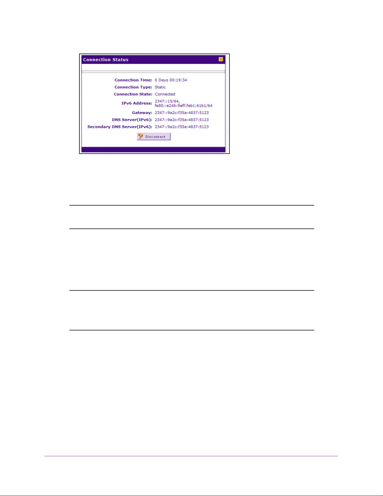
ProSAFE Dual WAN Gigabit WAN SSL VPN Firewall FVS336Gv2
The Connection Status screen shows a valid IP address and gateway. You are
connected to the Internet. For more information about the connections status, see
View the WAN Port Status and Terminate or Establish the Internet Connection on
page 594.
Note: If the configuration was not successful, see Troubleshoot the ISP
Connection on page 615.
Manually Configure a PPPoE IPv6 Internet Connection
To configure a PPPoE IPv6 Internet connection, enter the PPPoE IPv6 information that your
IPv6 ISP gave you. If you do not have this information, contact your IPv6 ISP.
Note: If your ISP requires MAC authentication and another MAC address was
previously registered with your ISP, you must configure that MAC address
on the VPN firewall (see
Firewall on page 70) before you begin the following procedure.
To manually configure a PPPoE IPv6 Internet connection for a WAN interface:
1. On your computer, launch an Internet browser.
2. In the address field of your browser, enter the IP address that was assigned to the VPN
firewall during the installation process.
The VPN firewall factory default IP address is 192.168.1.1.
Change the Advertised MAC Address of the VPN
The NETGEAR Configuration Manager Login screen displays.
3. In the Username field, type your user name and in the Password / Passcode field, type
your password.
Configure the IPv6 Internet and WAN Settings
97

ProSAFE Dual WAN Gigabit WAN SSL VPN Firewall FVS336Gv2
For the default administrative account, the default user name is admin and the default
password is password.
4. If you changed the default domain or were assigned a domain, from the Domain menu,
select the domain.
If you did not change the domain or were not assigned a domain, leave the menu
selection at geardomain.
5. Click the Login button.
The Router Status screen displays.
6. Select Network Configuration > WAN Settings > WAN Setup.
The WAN Setup screen displays the IPv4 settings.
7. In the upper right, select the IPv6 radio button.
The WAN Setup screen displays the IPv6 settings.
8. In the IPv6 WAN Settings table, click the Edit button for the W AN interface that you want to
configure.
The WAN IPv6 ISP Settings screen displays. The following figure shows the WAN2 IPv6
ISP Settings screen as an example.
Configure the IPv6 Internet and WAN Settings
98

ProSAFE Dual WAN Gigabit WAN SSL VPN Firewall FVS336Gv2
9. In the Internet Address section, from the IPv6 menu, select PPPoE.
10. In the PPPoE IPv6 section, enter the settings as described in the following table.
Note: If you do not know your PPPoE IPv6 information, contact your IPv6 ISP.
Setting Description
User Name The PPPoE user name that is provided by your ISP.
Password The PPPoE password that is provided by your ISP.
Configure the IPv6 Internet and WAN Settings
99

ProSAFE Dual WAN Gigabit WAN SSL VPN Firewall FVS336Gv2
Setting Description
DHCPv6 Option From the DHCPv6 Option menu, select a DHCPv6 server option, as directed by
your ISP:
• Disable-DHCPv6. DHCPv6 is disabled. You must specify the DNS servers in
the Primary DNS Server and Secondary DNS Server fields to receive an IP
address from the ISP.
• DHCPv6 StatelessMode. The VPN firewall generates its own IP WAN
address by using a combination of locally available information and router
advertisements but receives DNS server information from the ISP DHCPv6
server. Router advertisements include a prefix that identifies the subnet that
is associated with the WAN port. The IP address is formed by combining this
prefix and the MAC address of the WAN port. The IP address is a dynamic
address.
• DHCPv6 StatefulMode. The VPN firewall obtains an interface address,
configuration information such as DNS server information, and other
parameters from the ISP’s DHCPv6 server. The IP address is a dynamic
address.
• DHCPv6 Prefix Delegation. The VPN firewall obtains a prefix from the ISP
DHCPv6 server through prefix delegation, for example, 2001:db8:: /64. The
VPN firewall’s own stateless DHCPv6 server can assign this prefix to its IPv6
LAN clients. For more information about prefix delegation to IPv6 LAN clients,
see
Manage a Stateless DHCPv6 Server with Prefix Delegation for the LAN
on page 158.
Primary DNS Server If you selected Disable-DHCPv6 from the DHCPv6 Options menu, the IPv6 IP
address of the ISP primary DNS server.
Secondary DNS Server If you selected the Disable-DHCPv6 from the DHCPv6 Options menu, the IPv6
IP address of the ISP secondary DNS server.
11. Click the Apply button.
Your settings are saved.
12. Verify the connection:
a. Select Network Configuration > WAN Settings > WAN Setup.
The WAN Setup screen displays the IPv4 settings.
b. In the upper right, select the IPv6 radio button.
The WAN Setup screen displays the IPv6 settings (see the figure that is shown in
Step 7).
c. I n the IPv6 WAN Settings table, click the Status button for the WAN interface for
which you want to display the connection status.
The Connection Status pop-up screen displays. The following figure shows a static IP
address configuration, but the screen for PPPoE is similar. The IP addresses that are
shown in this figure are not related to any other examples in this manual.
Configure the IPv6 Internet and WAN Settings
100
 Loading...