

Page 1
Reference Manual for the ProSafe VPN Firewall FVS318v3
NETGEAR, Inc.
4500 Great America Parkway
Santa Clara, CA 95054 USA
202-10059-02
Version 3
January 2005
January 2005
Page 2

© 2005 by NETGEAR, Inc. All rights reserved.
Trademarks
NETGEAR is a trademark of Netgear, Inc.
Microsoft, Windows, and Wi ndow s NT are registered trademar ks of Microsoft Corporation.
Other brand and product names are registered trademarks or trademarks of their respective holders.
Statement of Conditions
In the interest of improving internal design, operational function, and/or reliability, NETGEAR reserves the right to
make changes to the products described in this document without notice.
NETGEAR does not assume any liability that may occur due to the use or application of the product(s) or circuit
layout(s) described herein.
Federal Communications Commission (FCC) Compliance Notice: Radio Frequency Notice
This equipment has been tested and found to comply with the limits for a Class B digital device, pursuant to
part 15 of the FCC Rules. These limits are designed to provide reasonable protection against harmful interference in a
residential installation. This equipment generates, uses, and can radiate radio frequency energy and, if not installed and
used in accordance with the instruct ions, may cause harmf ul interference to radio communications. However, there is no
guarantee that interference will not occur in a particular installation. If this equipment does cause harmful interference to
radio or television reception, which can be determined by turning the equipment off and on, the user is encouraged to try
to correct the interference by one or more of the following measures:
• Reorient or relocate the receiving antenna.
• Increase the separation between the equipment and receiver.
• Connect the equipment into an outlet on a circuit different from that to which the receiver is connected.
• Consult the dealer or an experienced radio/TV technician for help.
EN 55 022 Declaration of Conformance
This is to certify that the FVS318v3 ProSafe VPN Firewall is shielded against the generation of radio interference in
accordance with the application of Council Directive 89/336/EEC, Article 4a. Conformity is declared by the application
of EN 55 022 Class B (CISPR 22).
ii
January 2005
Page 3

Bestätigung des Herstellers/Importeurs
Es wird hiermit bestätigt, daß das FVS318v3 ProSafe VPN Firewall gemäß der im BMP T-AmtsblVfg 243/1991 und Vfg
46/1992 aufgeführten Bestimmungen entstört ist. Das vorschriftsmäßige Betreiben einiger Geräte (z.B. Testsender) kan n
jedoch gewissen Beschränkungen unterliegen. Lesen Sie dazu bitte die Anmerkungen in der Betriebsanleitung.
Das Bundesamt für Zulassungen in der Telekommunikation wurde davon unterrichtet, daß dieses Gerät auf den Markt
gebracht wurde und es ist berechtigt, die Serie auf die Erfüllung der Vorschriften hin zu überprüfen.
Certificate of the Manufacturer/Importer
It is hereby certified that the FVS318v3 ProSafe VPN Firewall has been suppressed in accordance with the conditions
set out in the BMPT-AmtsblVfg 243/1991 and Vfg 46/1992. The operation of some equipment (for example, test
transmitters) in accordance with the regulations may, however, be subject to certain restrictions. Please refer to the notes
in the operating instructions.
Federal Office for Telecommunications Approvals has been notified of the placing of this equipment on the market
and has been granted the right to test the series for compliance with the regulations.
Voluntary Contr ol Council for Interference (VCCI) Statement
This equipment is in the second category (information equipment to be used in a residential area or an adjacent area
thereto) and conforms to the standards set by the Voluntary Control Council for Interference by Data Processing
Equipment and Electronic Office Machines aimed at preventing radio interference in such residential areas.
When used near a radio or TV receiver , it may become the cause of radio interference.
Read instructions for correct handling.
January 2005
iii
Page 4

Product and Publication Details
Model Number: FVS318v3
Publication Date: January 2005
Product Family: Router
Product Name: FVS318v3 ProSafe VPN Firewall
Home or Business Product: Business
Language: English
iv
January 2005
Page 5

Contents
Chapter 1
About This Manual
Audience, Scope, Conventions, and Formats ................................................................1-1
How to Use This Manual ................................................................................................1-2
How to Print this Manual .................................................................................................1-3
Chapter 2
Introduction
Key Features of the VPN Firewall ..................................................................................2-1
A Powerful, True Firewall with Content Filtering ......................................................2-2
Security ....................................................................................................................2-2
Autosensing Ethernet Connections with Auto Uplink ...............................................2-3
Extensive Protocol Support ......................................................................................2-3
Easy Installation and Management ..........................................................................2-4
Maintenance and Support .................. .... ... ... ... .......................................... ... .... ... ... ..2-4
Package Contents ..........................................................................................................2-5
The FVS318v3 Front Panel ......................................................................................2-5
The FVS318v3 Rear Panel ......................................................................................2-6
NETGEAR-Related Products .........................................................................................2-7
NETGEAR Product Registration, Support, and Documentation ................................ .....2-7
Chapter 3
Connecting the Firewall to the Internet
Prepare to Install Your FVS318v3 ProSafe VPN Firewall ... ... ....... ... ... .... ... ... ... ... .... ... ... ..3-1
First, Connect the FVS318v3 .........................................................................................3-1
Now, Configure the FVS318v3 for Internet Access ........................................................3-4
Troubleshooting Tips ......................................................................................................3-6
Overview of How to Access the FVS318v3 VPN Firewall ..............................................3-8
How to Log On to the FVS318v3 After
Configuration Settings Have Been Applied ..............................................................3-9
How to Bypass the Configuration Assistant ...........................................................3-10
Contents v
January 2005
Page 6

Using the Smart Setup Wizard .....................................................................................3-11
How to Manually Configure Your Internet Connection ..... .......................................... ... 3-12
Chapter 4
Firewall Protection and
Content Filtering
Firewall Protection and Content Filtering Overview ............ ... .... ... ... ... .... ... ... ... ...............4-1
Block Sites ......................................................................................................................4-2
Using Rules to Block or Allow Specific Kinds of Traffic ..................................................4-3
Inbound Rules (Port Forwarding) .............................. ............................................... 4-5
Inbound Rule Example: A Local Public Web Server ..........................................4-5
Inbound Rule Example: Allowing a Videoconference from Restricted Addresses 4-6
Considerations for Inbound Rules .....................................................................4-6
Outbound Rules (Service Blocking) .........................................................................4-7
Outbound Rule Example: Blocking Instant Messenger .....................................4-7
Order of Precedence for Rules ................................................................................4-8
Default DMZ Server .................................................................................................4-8
Respond to Ping on Internet WAN Port ...................................................................4-9
Services ................................. ................................................ .......................................4-10
Using a Schedule to Block or Allow Specific Traffic ......................................................4-12
Time Zone ..............................................................................................................4-13
Getting E-Mail Notifications of Event Logs and Alerts ..................................................4-14
Viewing Logs of Web Access or Attempted Web Access .............................................4-16
Syslog ....................................................................................................................4-17
Chapter 5
Basic Virtual Private Networking
Overview of VPN Configuration ......................................................................................5-2
Client-to-Gateway VPN Tunnels ..............................................................................5-2
Gateway-to-Gateway VPN Tunnels .........................................................................5-2
Planning a VPN ..............................................................................................................5-3
VPN Tunnel Configuration .................................. ... .......................................... ... .... ... ... ..5-5
How to Set Up a Client-to-Gateway VPN Configuration .................................................5-5
Step 1: Configuring the Client-to-Gateway VPN Tunnel on the FVS318v3 ..............5-6
Step 2: Configuring the NETGEAR ProSafe VPN Client on the Remote PC ...........5-9
Monitoring the Progress and Status of the VPN Client Connection . ... ... ... ... .... ... ...5-16
Transferring a Security Policy to Another Client .......................... .... ... ... ... ... .... ... ...5-18
Exporting a Security Policy ................. ... .......................................... ... ... .... ...... 5-18
vi Contents
January 2005
Page 7

Importing a Security Policy ..............................................................................5-19
How to Set Up a Gateway-to-Gateway VPN Configuration ....... ................................... 5-20
Procedure to Configure a Gateway-to-Gateway VPN Tunnel ................................5-21
VPN Tunnel Control ..................... .... ... ... ... .... ... ... ... ... .... .......................................... ......5-26
Activating a VPN Tunnel ........................................................................................5-26
Start Using a VPN Tunnel to Activate It ...........................................................5-26
Using the VPN Status Page to Activate a VPN Tunnel ....................................5-26
Activate the VPN Tunnel by Pinging the Remote Endpoint .............................5-27
Verifying the Status of a VPN Tunnel .....................................................................5-29
Deactivating a VPN Tunnel ....... ... ... ... .... ................................................................5-30
Using the Policy Table on the VPN Policies Page to Deactivate a VPN Tunnel 5-30
Using the VPN Status Page to Deactivate a VPN Tunnel ......... ... ... ... ... .... ... ...5-31
Deleting a VPN Tunnel ...........................................................................................5-32
Chapter 6
Advanced Virtual Private Networking
Overview of FVS318v3 Policy-Based VPN Configuration .............................................. 6-1
Using Policies to Manage VPN Traffic .....................................................................6-2
Using Automatic Key Management ..................................... ................................... .. 6-2
IKE Policies’ Automatic Key and Authentication Management ................................6-3
VPN Policy Configuration for Auto Key Negotiation ..................... ............................ 6-5
VPN Policy Configuration for Manual Key Exchange ...............................................6-9
Using Digital Certificates for IKE Auto-Policy Authentication .......................................6-13
Certificate Revocation List (CRL) ...........................................................................6-14
Walk-Through of Configuration Scenarios on the FVS318v3 .......................................6-14
VPN Consortium Scenario 1:
Gateway-to-Gateway with Preshared Secrets .......................................................6-15
FVS318v3 Scenario 1: FVS318v3 to Gateway B IKE and VPN Policies ...............6-16
How to Check VPN Connections ...........................................................................6-21
Testing the Gateway A FVS318v3 LAN and the Gateway B LAN ...................6-21
FVS318v3 Scenario 2: FVS318v3 to FVS318v3 with RSA Certificates .................6-22
Chapter 7
Maintenance
Viewing VPN Firewall Status Information .......................................................................7-1
Viewing a List of Attached Devices .................................................................................7-5
Upgrading the Firewall Software ....................................................................................7-5
Configuration File Management .....................................................................................7-7
Contents vii
January 2005
Page 8

Backing Up the Configuration ..................................................................................7-7
Restoring the Configuration .....................................................................................7-7
Erasing the Configuration .........................................................................................7-8
Changing the Administrator Password ...........................................................................7-8
Chapter 8
Advanced Configuration
How to Configure Dynamic DNS ....................................................................................8-1
Using the LAN IP Setup Options ....................................................................................8-2
Configuring LAN TCP/IP Setup Parameters ............................................................8-3
Using the Firewall as a DHCP server .......................................................................8-4
Using Address Reservation ......................................................................................8-5
Configuring Static Routes ...............................................................................................8-5
Static Route Example ...............................................................................................8-7
Enabling Remote Management Access .........................................................................8-7
Chapter 9
Troubleshooting
Basic Functioning ...........................................................................................................9-1
Power LED Not On ...................................................................................................9-1
LEDs Never Turn Off ................................................................................................9-2
LAN or Internet Port LEDs Not On ......... ... ... ... ... .... ... ... .......................................... ..9-2
Troubleshooting the Web Configuration Interface ..........................................................9-3
Troubleshooting the ISP Connection ..............................................................................9-4
Troubleshooting a TCP/IP Network Using a Ping Utility .................................................9-5
Testing the LAN Path to Your Firewall ......................................................................9-5
Testing the Path from Your PC to a Remote Device ................................................9-6
Restoring the Default Configuration and Password ............... .........................................9-7
Problems with Date and Time .........................................................................................9-7
Appendix A
Technical Specifications
Appendix B
Network, Routing, and Firewall Basics
Related Publications ...................................................................................................... B-1
Basic Router Concepts .................................................................................................. B-1
What is a Router? ................................................................................................... B-2
Routing Information Protocol ................................................................................... B-2
IP Addresses and the Internet .. ... .... ... ... ... .... ................................................................. B-2
viii Contents
January 2005
Page 9

Netmask .................................... ................................................................ ..............B-4
Subnet Addressing .................................................................................................. B-5
Private IP Addresses ................................. ... ... ... .......................................... ........... B-7
Single IP Address Operation Using NAT ....................................................................... B-8
MAC Addresses and Address Resolution Protocol ................................................. B-9
Related Documents ................................................................................................. B-9
Domain Name Server .............................................................................................. B-9
IP Configuration by DHCP ............................... .......................................... ... ... ... .... ..... B-10
Internet Security and Firewalls .................................................................................... B-10
What is a Firewall? .................................................................................................B-11
Stateful Packet Inspection .................................. ... ... .... ... ... .............................B-11
Denial of Service Attack ..................................................................................B-11
Ethernet Cabling ................................. ... ... .... ... .......................................... ... ... ... .... ... ...B-11
Category 5 Cable Quality ...................................................................................... B-12
Inside Twisted Pair Cables .................................................................................... B-13
Uplink Switches, Crossover Cables, and MDI/MDIX Switching ............................ B-14
Appendix C
Virtual Private Networking
What is a VPN? ............................................................................................................. C-1
What Is IPSec and How Does It Work? ......................................................................... C-2
IPSec Security Features .............................. ... ... .... ... ... ... .... .................................... C-2
IPSec Components ...................... ... ... .... ... ... ... .......................................... ..............C-2
Encapsulating Security Payload (ESP) ...................................................................C-3
Authentication Header (AH) ............................... .... ... ... ... .... ... ... ... .... ....................... C-4
IKE Security Association ........... .......................................... ... ... ... ........................... C-4
Mode ...................................... ...................... .................... ...................... ........... C-5
Key Management ....................................................................................................C-6
Understand the Process Before You Begin ................................................................... C-6
VPN Process Overview ......... ... ... .... ... .......................................... ................................. C-7
Network Interfaces and Addresses ......................................................................... C-7
Interface Addressing ......................................................................................... C-7
Firewalls ........................................................................................................... C-8
VPN Tunnel Between Gateways .............................................................................C-8
VPNC IKE Security Parameters ......... ... ... .... ... ............................................................ C-10
VPNC IKE Phase I Parameters .............................................................................C-10
Contents ix
January 2005
Page 10

VPNC IKE Phase II Parameters ............................................................................ C-11
Testing and Troubleshooting ........................................................................................ C-11
Additional Reading ...................... .... ... .......................................... ... ... .... ..................... C-11
Appendix D
Preparing Your Network
Preparing Your Computers for TCP/IP Networking ................................................ ... ... . D-1
Configuring Windows 95, 98, and Me for TCP/IP Networking ....................................... D-2
Install or V erify Windows Networking Components ................................................. D-2
Enabling DHCP to Automatically Configure TCP/IP Settings .................................D-4
Selecting Windows’ Internet Access Method .......................................................... D-6
Verifying TCP/IP Properties .................................................................................... D-6
Configuring Windows NT4, 2000 or XP for IP Networking ............................................D-7
Install or V erify Windows Networking Components ................................................. D-7
Enabling DHCP to Automatically Configure TCP/IP Settings .................................D-8
DHCP Configuration of TCP/IP in Windows XP ..................................................... D-8
DHCP Configuration of TCP/IP in Windows 2000 ................................................ D-10
DHCP Configuration of TCP/IP in Windows NT4 .................................................. D-13
Verifying TCP/IP Properties for Windows XP, 2000, and NT4 .............................. D-15
Configuring the Macintosh for TCP/IP Networking ...................................................... D-16
MacOS 8.6 or 9.x ...................... ... ... ... .... ... ... ... ... .... .......................................... .....D-16
MacOS X ...... ... .......................................... .......................................... ..................D-16
Verifying TCP/IP Properties for Macintosh Computers ... .... ... ... ... .... ... ... ... ... .... .....D-17
Verifying the Readiness of Your Internet Account ....................................................... D-18
Are Login Protocols Used? ................................................................................... D-18
What Is Your Configuration Information? .............................................................. D-18
Obtaining ISP Configuration Information for Windows Computers .......................D-19
Obtaining ISP Configuration Information for Macintosh Computers .....................D-20
Restarting the Network ................................................................................................D-21
Appendix E
VPN Configuration of NETGEAR FVS318v3
Case Study Overview .................................................................................................... E-1
Gathering the Network Information ......................................................................... E-1
Configuring the Gateways ....................................................................................... E-2
Activating the VPN Tunnel ...................................................................................... E-5
The FVS318v3-to-FVS318v3 Case ............................................................................... E-6
x Contents
January 2005
Page 11

Configuring the VPN Tunnel .................................. ... ... ... .... ... ................................. E-6
Viewing and Editing the VPN Parameters ............................................................... E-9
Initiating and Checking the VPN Connections .......................................................E-11
The FVS318v3-to-FVS318v2 Case ............................................................................. E-13
Configuring the VPN Tunnel .................................. ... ... ... .... ... ............................... E-13
Viewing and Editing the VPN Parameters ........................................ ............ ......... E-16
Initiating and Checking the VPN Connections ...................................................... E-18
The FVS318v3-to-FVL328 Case ................................................................................. E-20
Configuring the VPN Tunnel .................................. ... ... ... .... ... ............................... E-20
Viewing and Editing the VPN Parameters ........................................ ............ ......... E-23
Initiating and Checking the VPN Connections ...................................................... E-25
The FVS318v3-to-VPN Client Case ............................................................................ E-27
Client-to-Gateway VPN Tunnel Overview ............................................................. E-27
Configuring the VPN Tunnel .................................. ... ... ... .... ... ............................... E-28
Initiating and Checking the VPN Connections ...................................................... E-36
Glossary
List of Glossary Terms ...................................................................................................G-1
Numeric .........................................................................................................................G-1
A ....................................................................................................................................G-1
B ....................................................................................................................................G-2
C ..................................... ........................................................................... ....................G-2
D ..................................... ........................................................................... ....................G-3
E ....................................................................................................................................G-4
G ..................................... .............................................. .................................................G-4
I .................................... ............. .......... ............. ............. ............. ............. ............ ...........G-4
L ...................................... ................. ............. ................ ................ ................ .................G-6
M ..................................... ............. ............. ............. ............. ............. ............. .................G-6
P ....................................................................................................................................G-7
Q ..................................... .............................................. .................................................G-8
R ..................................... ........................................................................... ....................G-8
S ....................................................................................................................................G-9
T ....................................................................................................................................G-9
U ..................................... ........................................................................... ....................G-9
W ...................................................................................................................................G-9
Contents xi
January 2005
Page 12

xii Contents
January 2005
Page 13
Chapter 1
About This Manual
This chapter describes the intended audience, scope, conventions, and formats of this manual.
Audience, Scope, Conventions, and Formats
This reference manual assumes that the reader has basic to intermediate computer and Internet
skills. However, basic computer network, Internet, firewall, and VPN technologies tutorial
information is provided in the Appendices and on the NETGEAR Web site.
This guide uses the following typographical conventions:
Table 1-1. Typographical Conventions
italics Emphasis, books, CDs, URL names
bold User input
fixed Screen text, file and server names, extensions, commands, IP addresses
This guide uses the following formats to highlight special messages:
Note: This format is used to highlight information of importance or special interest.
This manual is written for the FVS318v3 VPN Firewall according to these specifications.:
Table 1-2. Manual Scope
Product Version FVS318v3 ProSafe VPN Firewall
Manual Publication Date January 2005
Note: Product updates are available on the NETGEAR, Inc. Web site at
http://kbserver.netgear.com/products/FVS318v3.asp.
About This Manual 1-1
January 2005
Page 14
Reference Manual for the ProSafe VPN Firewall FVS318v3
How to Use This Manual
The HTML version of this manual includes the following:
• Buttons, and , for browsing forwards or backwards through the manual one page
at a time
• A button that displays the table of contents and an button. Double-click on a
link in the table of contents or index to navigate directly to where the topic is described in the
manual.
• A button to access the full NETGEAR, Inc. online Knowledge Base for the
product model.
• Links to PDF versions of the full manual and individual chapters.
1-2 About This Manual
January 2005
Page 15

Reference Manual for the ProSafe VPN Firewall FVS318v3
How to Print this Manual
To print this manual you can choose one of the following several options, according to your needs.
• Printing a Page in the HTML View.
Each page in the HTML version of the manual is dedicated to a major topic. Use the Print
button on the browser toolbar to print the page contents.
• Printing a Chapter.
Use the PDF of This Chapter link at the top left of any page.
– Click the “PDF of This Chapter” link at the top right of any page in the chapter you want
to print. The PDF version of the chapter you were viewing opens in a browser window.
Note: Your computer must have the free Adobe Acrobat reader installed in order to view
and print PDF files. The Acrobat reader is available on the Adobe Web site at
http://www.adobe.com.
– Click the print icon in the upper left of the window.
Tip: If your printer supports printing two pages on a single sheet of paper, you can save
paper and printer ink by selecting this feature.
• Printing the Full Manual.
Use the Complete PDF Manua l link at the top left of any page.
– Click the Complete PDF Manual link at the top left of any page in the manual. The PDF
version of the complete manual opens in a browser window.
– Click the print icon in the upper left of the window.
Tip: If your printer supports printing two pages on a single sheet of paper, you can save
paper and printer ink by selecting this feature.
About This Manual 1-3
January 2005
Page 16

Reference Manual for the ProSafe VPN Firewall FVS318v3
1-4 About This Manual
January 2005
Page 17

Chapter 2
Introduction
This chapter describes the features of the NETGEAR FVS318v3 ProSafe VPN Firewall.
Key Features of the VPN Firewall
The FVS318v3 ProSafe VPN Firewall with eight-port switch connects your local area network
(LAN) to the Internet through an external access device such as a cable modem or DSL modem.
The FVS318v3 is a complete security solution that protects your network from attacks and
intrusions. Unlike simple Internet sharing firewalls that rely on Network Address Translation
(NAT) for security, the FVS318v3 uses stateful packet inspection for Denial of Service attack
(DoS) protection and intrusion detection. The FVS318v3 allows Internet access for up to 253
users. The FVS318v3 VPN Firewall provides you with multiple Web content filtering options,
plus browsing activity reporting and instant alerts — both via e-mail. Parents and network
administrators can establish restricted access policies based on time-of-day, Web site addresses
and address keywords, and share high-speed cable/DSL Internet access for up to 253 personal
computers. In addition to NAT, the built-in firewall protects you from hackers.
With minimum setup, you can install and use the firewall within minutes.
The FVS318v3 VPN Firewall provides the following features:
• Easy, Web-based setup for installation and management.
• Content filtering and site blocking security.
• Built-in eight-port 10/100 Mbps switch.
• Ethernet connection to a WAN device, such as a cable modem or DSL modem.
• Extensive protocol support.
• Login capability.
• Front panel LEDs for easy monitoring of status and activity.
• Flash memory for firmware upgrade.
Introduction 2-1
January 2005
Page 18

Reference Manual for the ProSafe VPN Firewall FVS318v3
A Powerful, True Firewall with Content Filtering
Unlike simple Internet sharing NAT firewalls, the FVS318v3 is a true firewall, using stateful
packet inspection to defend against hacker attacks. Its firewall features include:
• DoS protection.
Automatically detects and thwarts DoS attacks such as Ping of Death, SYN Flood, LAND
Attack, and IP Spoofing.
• Blocks unwanted traffic from the Internet to your LAN.
• Blocks access from your LAN to Internet locations or services that you specify as off-limits.
• Logs security incidents.
The FVS318v3 logs security events such as blocked incoming traffic, port scans, attacks, and
administrator logins. You can configure the firewall to email the log to you at specified
intervals. You can also configure the firewall to send immediate alert messages to your e-mail
address or email pager whenever a significant event occurs.
• With its content filtering feature, the FVS318v3 prevents objectionable content from reaching
your PCs. The firewall allows you to control access to Internet content by screening for
keywords within Web addresses. You can configure the firewall to log and report attempts to
access objectionable Internet sites.
Security
The FVS318v3 VPN Firewall is equipped with several features designed to maintain security, as
described in this section.
• PCs Hidden by NAT
NAT opens a temporary path to the Internet for requests originating from the local network.
Requests originating from outside the LAN are discarded, preventing users outside the LAN
from finding and directly accessing the PCs on the LAN.
• Port Forwarding with NAT
Although NAT prevents Internet locations from directly accessing the PCs on the LAN, the
firewall allows you to direct incoming traffic to specific PCs based on the service port number
of the incoming request, or to one designated “DNS” host computer. You can specify
forwarding of single ports or ranges of ports.
2-2 Introduction
January 2005
Page 19

Reference Manual for the ProSafe VPN Firewall FVS318v3
Autosensing Ethernet Connections with Auto Uplink
With its internal eight-port 10/100 switch, the FVS318v3 can connect to either a 10 Mbps standard
Ethernet network or a 100 Mbps Fast Ethernet network. Both the LAN and WAN interfaces are
autosensing and capable of full-duplex or half-duplex operation.
TM
The firewall incorporates Auto Uplink
technology. Each Ethernet port automatically senses
whether the Ethernet cable plugged into the port should have a normal connection such as to a PC
or an uplink connection such as to a switch or hub. That port then configures itself to the correct
configuration. This feature also eliminates the need to worry about crossover cables, as Auto
Uplink will accommodate either type of cable to make the right connection.
Extensive Protocol Support
The FVS318v3 VPN Firewall supports the Transmission Contro l Protoco l/In ternet Proto col (TCP/
IP) and Routing Information Protocol
Appendix B, “Network, Routing, and Firewall Basics.”
• IP Address Sharing by NAT
The FVS318v3 VPN Firewall allows several networked PCs to share an Internet account using
only a single IP address, which may be statically or dynamically assigned by your Internet
service provider (ISP). This technique, known as NAT, allows the use of an inexpensive
single-user ISP account.
(RIP). For further information about TCP/IP, refer to
• Automatic Configuration of Attached PCs by DHCP
The FVS318v3 VPN Firewall dynamically assigns network configuration information,
including IP, gateway, and Domain Name Server (DNS) addresses, to attached PCs on the
LAN using the Dynamic Host Configuration Protocol (DHCP). This feature greatly simplifies
configuration of PCs on your local network.
• DNS Proxy
When DHCP is enabled and no DNS addresses are specified, the firewall provides its own
address as a DNS server to the attached PCs. The firewall obtains actual DNS addresses from
the ISP during connection setup and forwards DNS requests from the LAN.
• Point-to-Point Protocol over Ethernet (PPPoE)
PPPoE is a protocol for connecting remote hosts to the Internet over a DSL connection by
simulating a dial-up connection. This feature eliminates the need to run a login program such
as Entersys or WinPOET on your PC.
Introduction 2-3
January 2005
Page 20
Reference Manual for the ProSafe VPN Firewall FVS318v3
Easy Installation and Management
You can install, configure, and operate the FVS318v3 ProSafe VPN Firewall within minutes after
connecting it to the network. The following features simplify installation and management tasks:
• Browser-based management
Browser-based configuration allows you to easily configure your firewall from almost any
type of personal computer, such as Windows, Macintosh, or Linux. A user-friendly Setup
Wizard is provided and online help documentation is built into the browser-based Web
Management Interface.
• Smart Wizard
The FVS318v3 VPN Firewall automatically senses the type of Internet connection, asking you
only for the information required for your type of ISP account.
• Diagnostic functions
The firewall incorporates built-in diagnostic functions such as Ping, DNS lookup, and remote
reboot.
• Remote management
The firewall allows you to login to the Web Management Interface from a remote location on
the Internet. For security, you can limit remote management access to a specified remote IP
address or range of addresses, and you can choose a nonstandard port number.
• Visual monitoring
The FVS318v3 VPN Firewall’s front panel LEDs provide an easy way to monitor its status
and activity.
Maintenance and Support
NETGEAR offers the following features to help you maximize your use of the FVS318v3 VPN
Firewall:
• Flash memory for firmware upgrade.
• Free technical support seven days a week, 24 hours a day.
Note: The FVS318v3 firmware is not backward compatible with earlier versions of the
FVS318 firewall.
2-4 Introduction
January 2005
Page 21
Reference Manual for the ProSafe VPN Firewall FVS318v3
Package Contents
The product package should contain the following items:
• FVS318v3 ProSafe VPN Firewall.
•AC power adapter.
• Category 5 (Cat 5) Ethernet cable.
• Installation Guide.
• Resource CD (240-10114-02) for ProSafe VPN Fir ewall, including:
— This guide.
— Application Notes and other helpful information.
• Registration and Warranty Card.
If any of the parts are incorrect, missing, or damaged, contact your NETGEAR dealer. Keep the
carton, including the original packing materials, in case you need to return the firewall for repair.
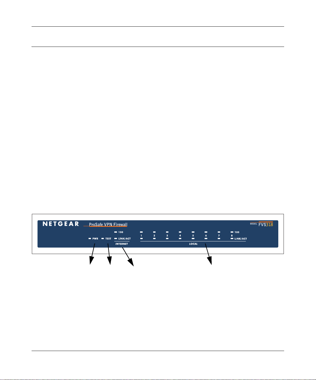
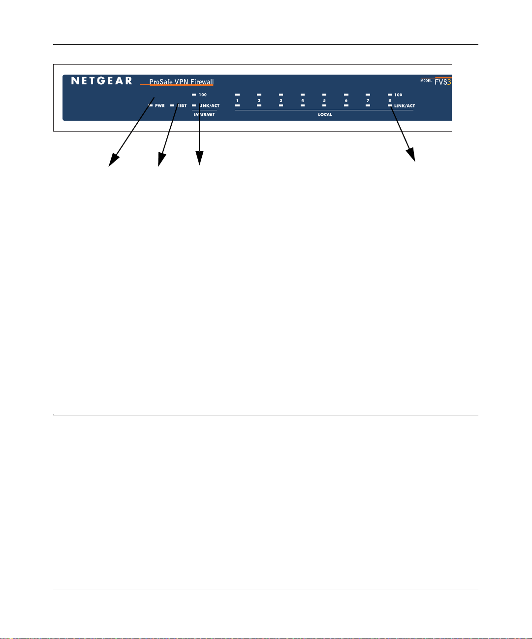
The FVS318v3 Front Panel
The front panel of the FVS318v3 VPN Firewall contains the status LEDs described below.
PWR
Figure 2-1: FVS318v3 front panel
Test
Internet
LOCAL Ports
You can use some of the LEDs to verify connections. Viewed from left to right, Table 2-1
describes the LEDs on the front panel of the firewall. These LEDs are green when lit.
Introduction 2-5
January 2005
Page 22
Reference Manual for the ProSafe VPN Firewall FVS318v3
Table 2-1. LED Descriptions
LED Label Activity Description
PWR On Power is supplied to the firewall.
TEST On
Off
INTERNET
100 (100 Mbps) On
Off
LINK/ACT
(Link/Activity)
LOCAL
100 (100 Mbps) On
LINK/ACT
(Link/Activity)
On
Blinking
Off
On
Blinking
The system is initializing.
The system is ready and running.
The Internet (WAN) port is operating at 100 Mbps.
The Internet (WAN) port is operating at 10 Mbps.
The Internet port has detected a link with an attached device.
Data is being transmitted or received by the Internet port.
The Local port is operating at 100 Mbps.
The Local port is operating at 10 Mbps.
The Local port has detected a link with an attached device.
Data is being transmitted or received by the Local port.
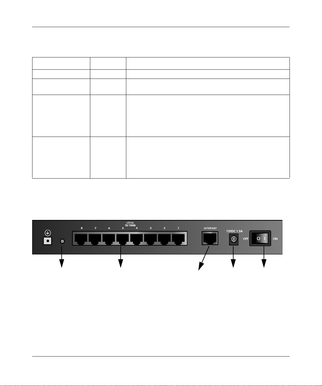
The FVS318v3 Rear Panel
The rear panel of the FVS318v3 VPN Firewall contains the port connections listed below.
FACTORY DEFAULTS
Reset Button
LOCAL
Ports
Figure 2-2: FVS318v3 rear panel
DC PowerINTERNET
Port
ON/OFF
Switch
Viewed from left to right, the rear panel contains the following features:
• Factory default reset push button
• Eight Ethernet LAN ports
• Internet Ethernet WAN port for connecting the firewall to a cable or DSL modem
2-6 Introduction
January 2005
Page 23

Reference Manual for the ProSafe VPN Firewall FVS318v3
• DC power input
• ON/OFF switch
NETGEAR-Related Products
NETGEAR products related to the FVS318v3 are listed in the following table:
Table 2-2. NETGEAR-Related Products
Category Wireless Wired
Notebooks WAG511 108 Mbps Dual Band PC Card
WG511T 108 Mbps PC Card
WG511 54 Mbps PC Card
WG111 54 Mbps USB 2.0 Adapter
MA521 802.11b PC Card
MA111 802.11b USB Adapter
Desktops WAG311 108 Mbps Dual Band PCI Adapter
WG311T 108 Mbps PCI Adapter
WG311 54 Mbps PCI Adapter
WG111 54 Mbps USB 2.0 Adapter
MA111 802.11b USB Adapter
PDAs MA701 802.11b Compact Flash Card
Antennas and
Accessories
ANT24O5 5 dBi Antenna
ANT2409 Indoor/Outdoor 9 dBi Antenna
ANT24D18 Indoor/Outdoor 18 dBi Antenna
Antenna Cables–1.5, 3, 5, 10, and 30 m lengths
VPN01L and VPN05L ProSafe VPN Client Software
FA511 CardBus Adapter
FA120 USB 2.0 Adapter
FA311 PCI Adapter
FA120 USB 2.0 Adapter
NETGEAR Product Registration, Support, and Documentation
Register your product at http://www.NETGEAR.com/register. Registration is required before you
can use our telephone support service.
Product updates and Web support are always available by going to: http://kbserver.netgear.com.
Documentation is available on the Resource CD and at http://kbserver.netgear.com.
Introduction 2-7
January 2005
Page 24

Reference Manual for the ProSafe VPN Firewall FVS318v3
When the VPN firewall router is connected to the Internet, click the Knowledge Base or the
Documentation link under the Web Support menu to view support information or the
documentation for the VPN firewall router.
2-8 Introduction
January 2005
Page 25

Chapter 3
Connecting the Firewall to the Internet
This chapter describes how to set up the firewall on your LAN, connect to the Internet, perform
basic configuration of your FVS318v3 ProSafe VPN Firewall using the Setup Wizard, or how to
manually configure your Internet connection.
Follow these instructions to set up your firewall.
Prepare to Install Your FVS318v3 ProSafe VPN Firewall
• For Cable Modem Service: When you perform the VPN firewall router setup steps be sure to
use the computer you first registered with your cable ISP.
• For DSL Service: You may need information such as the DSL login name/e-mail address and
password in order to complete the VPN firewall router setup.
Before proceeding with the VPN firewall router installation, familiarize yourself with the contents
of the Resource CD (240-10114-02) for ProSafe VPN Firewall, especially this manual and the
animated tutorials for configuring networking on PCs.
First, Connect the FVS318v3
1. CONNECT THE CABLES BETWEEN THE FVS318V3, COMPUTER, AND MODEM
a. Turn off your computer.
b. Turn off the cable or DSL broadband modem.
Connecting the Firewall to the Internet 3-1
January 2005
Page 26
Reference Manual for the ProSafe VPN Firewall FVS318v3
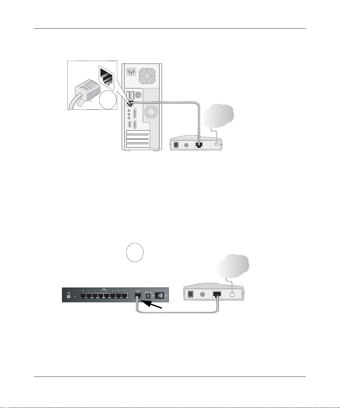
Locate the Ethernet cable (Cable 1 in the diagram) that connects your PC to the modem.
c.
A
&DEOH
,QWHUQHW
&RPSXWHU
Figure 3-1: Disconnect the Ethernet cable from the computer
d.
Disconnect the cable at the computer end only, point A in the diagram.
e. Look at the label on the bottom of the VPN firewall router. Locate the Internet port.
Securely insert the Ethernet cable from your modem (Cable 1 in the diagram below) into
the Internet port of the VPN firewall router as shown in point B of the diagram.
0RGHP
B
Internet
port
Internet
Firewall
Figure 3-2: Connect the VPN firewall router to the modem
3-2 Connecting the Firewall to the Internet
Cable 1
January 2005
Modem
Page 27
Reference Manual for the ProSafe VPN Firewall FVS318v3
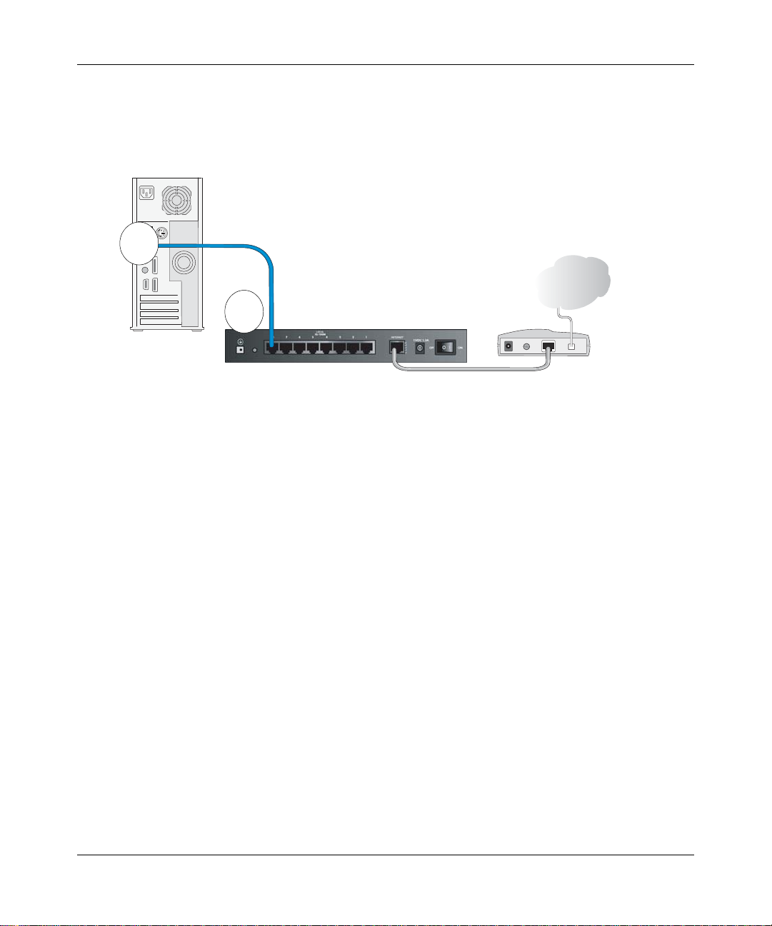
Securely insert the blue cable that came with your VPN firewall router (the blue
f.
NETGEAR cable in the diagram below) into a LOCAL port on the firewall such as
LOCAL port 8 (point C in the diagram), and the other end into the Ethernet port of your
computer (point D in the diagram).
Blue NETGEAR
D
Cable
Internet
C
Computer
Local Ports
Figure 3-3: Connect the computer to the VPN firewall router
Your network cables are connected and you are ready to restart your network.
Firewall
Modem
2. RESTART YOUR NETWORK IN THE CORRECT SEQUENCE
Warning: Failure to restart your network in the correct sequence could prevent you from
connecting to the Internet.
a. First, turn on the broadband modem and wait two minutes.
b. Now, plug in the power cord to your VPN firewall router and wait one minute.
c. Last, turn on your computer.
Note: For DSL customers, if software logs you in to the Internet, do not run that software. Y ou
may need to go to the Internet Explorer T ools menu, Internet Options, Connections tab page
where you can select “Never dial a connection.”
Connecting the Firewall to the Internet 3-3
January 2005
Page 28
Reference Manual for the ProSafe VPN Firewall FVS318v3
Power Internet Local Port 8Test
Figure 3-4: Status lights
d.
Check the VPN firewall router status lights to verify the following:
• PWR: The power light should turn solid green. If it does not, see “Troubleshooting
Tips” on page 3-6.
• TEST: The test light blinks when the firewall is first turned on then goes off. If after
two minutes it is still on, see “Troubleshooting Tips” on page 3-6.
• INTERNET: The Internet LINK light should be lit. If not, make sure the Ethernet cable
is securely attached to the VPN firewall router Internet port and the modem, and the
modem is powered on.
• LOCAL: A LOCAL light should be lit. Green on the 100 line indicates your computer
is communicating at 100 Mbps; off on the 100 line indicates 10 Mbps. If a LOCAL
light is not lit, check that the Ethernet cable from the computer to the firewall is
securely attached at both ends, and that the computer is turned on.
Now, Configure the FVS318v3 for Internet Access
1. From the Ethernet connected PC you just set up, open a browser such as Internet Explorer or
Netscape® Navigator.
3-4 Connecting the Firewall to the Internet
January 2005
Page 29
Reference Manual for the ProSafe VPN Firewall FVS318v3
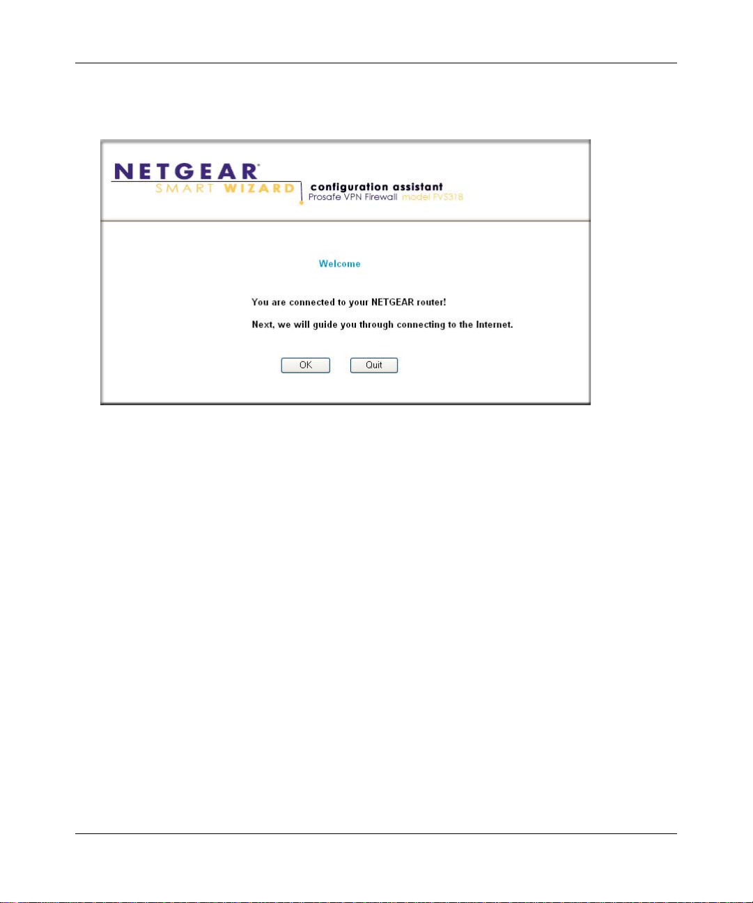
With the VPN firewall router in its factory default state, your browser will automatically
display the NETGEAR Smart Wizard Configuration Assistant welcome page.
Figure 3-5: NETGEAR Smart Wizard Configuration Assistant welcome screen
Note: If you do not see this page, type http://www.routerlogin.net in the browser address bar
and press Enter. If you still cannot see this screen, see “How to Bypass the Configuration
Assistant” on page 3-10.
If you cannot connect to the VPN firewall router, verify your computer networking setup. It
should be set to obtain both IP and DNS server addresses automatically, which is usually so.
For help with this, see Appendix D, “Preparing Your Network or the animated tutorials on the
Resource CD.
2. Click OK. Follow the prompts to proceed with the Smart Wizard Configuration Assistant to
connect to the Internet.
Connecting the Firewall to the Internet 3-5
January 2005
Page 30
Reference Manual for the ProSafe VPN Firewall FVS318v3
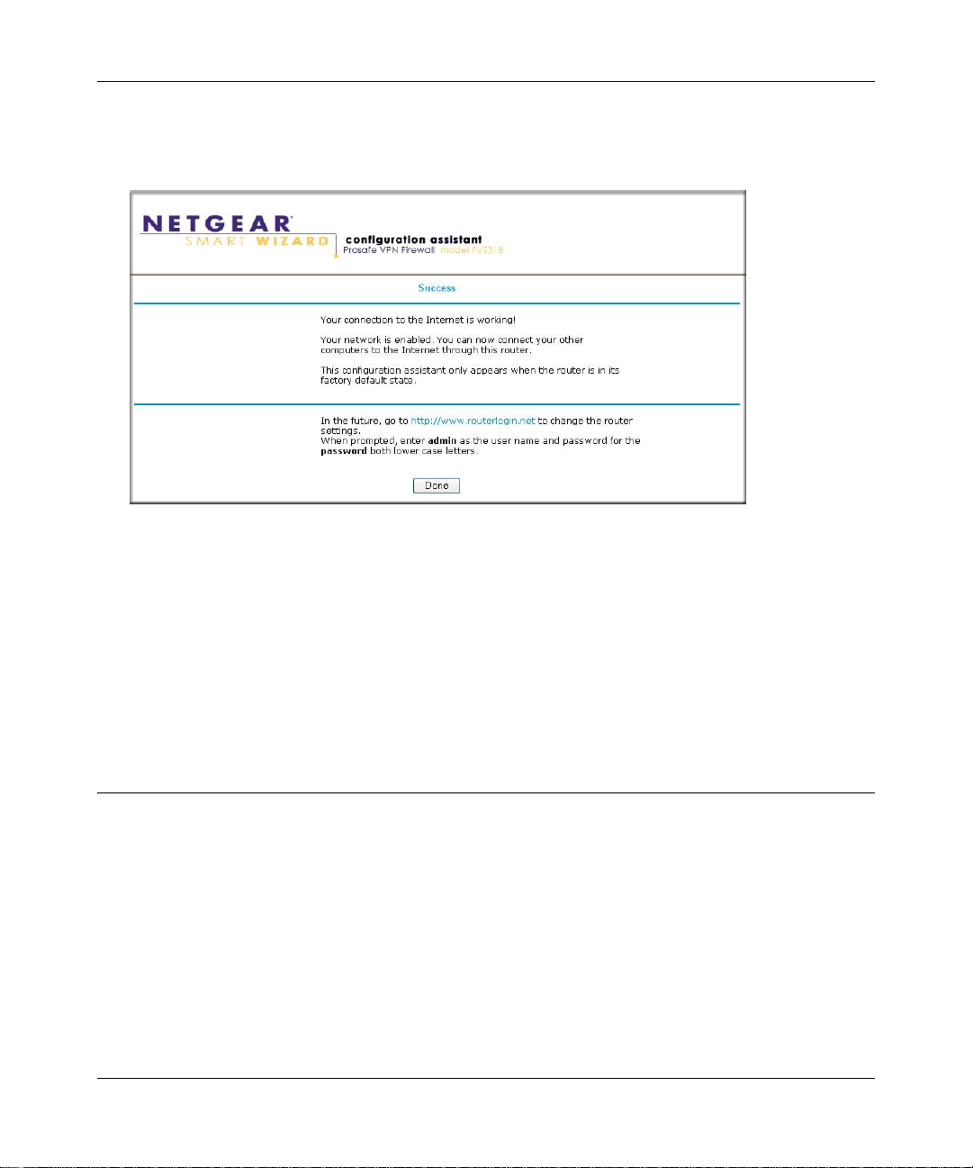
Click Done to finish. If you have trouble connecting to the Internet, see “Troubleshooting
3.
Tips” on page 3-6 to correct basic problems.
Figure 3-6: NETGEAR Smart Wizard Configuration Assistant success screen
Note: The Smart Wizard Configuration Assistant only ap pe a r s wh en the firewall is in its factory
default state. After you configure the VPN firewall router, it will not appear again. You can always
connect to the firewall to change its settings. To do so, open a browser such as Internet Explorer
and go to http://www.routerlogin.net. Then, when prompted, enter admin as the user name and
password for the password both in lower case letters.
You are now connected to the Internet!
Troubleshooting Tips
Here are some tips for correcting simple problems you may have.
Be sure to restart your network in this sequence:
1. Turn off the VPN firewall router, shut down the computer, and unplug and turn of f the modem.
2. Turn on the modem and wait two minutes
3. Turn on the VPN firewall router and wait one minute
4. Turn on the computer.
3-6 Connecting the Firewall to the Internet
January 2005
Page 31

Reference Manual for the ProSafe VPN Firewall FVS318v3
Make sure the Ethernet cables are securely plugged in.
• The Internet link light on the VPN firewall router will be lit if the Ethernet cable to the VPN
firewall router from the modem is plugged in securely and the modem and VPN firewall router
are turned on.
• For each powered on computer connected to the VPN firewall router with a securely plugged
in Ethernet cable, the corresponding VPN firewall router LOCAL port link light will be lit.
The labels on the front and back of the VPN firewall router identify the number of each
LOCAL port.
Make sure the network settings of the computer are correct.
• LAN connected computers must be configured to obtain an IP address automatically via
DHCP. Please see Appendix D, “Preparing Your Network or the animated tutorials on the
Resource CD for help with this.
• Some cable modem ISPs require you to use the MAC address of the computer registered on
the account. If so, in the Router MAC Address section of the Basic Settings menu, select “Use
this Computer’s MAC Address.” The firewall will then capture and use the MAC address of
the computer that you are now using. You must be using the computer that is registered with
the ISP. Click Apply to save your settings. Restart the network in the correct sequence.
Use the status lights on the front of the FVS318v3 to verify correct firewall operation.
If the FVS318v3 power light does not turn solid green or if the test light does not go off within
two minutes after turning the firewall on, reset the firewall according to the instructions in
“Backing Up the Configuration” on page 7-7.
Connecting the Firewall to the Internet 3-7
January 2005
Page 32

Reference Manual for the ProSafe VPN Firewall FVS318v3
Overview of How to Access the FVS318v3 VPN Firewall
The table below describes how you access the VPN firewall router, depending on the state of the
VPN firewall router.
Table 3-1. Ways to access the firewall
Firewall Stat e Access Options Description
Factory Default
Note: The VPN
firewall router is
supplied in the
factory default state.
Also, the factory
default state is
restored when you
use the factory reset
button. See
“Backing Up the
Configuration” on
page 7-7 for more
information on this
feature.
Configuration
Settings Have Been
Applied
Automatic Access via
the Smart Wizard
Configuration
Assistant
Manually enter a URL
to bypass the Smart
Wizard Configuration
Assistant
Enter the standard
URL to access the
VPN firewall router
Enter the IP address
of the VPN firewall
router
Any time a browser is opened on any computer connected to
the VPN firewall router, the VPN firewall router will
automatically connect to that browser and display the
Configuration Assistant welcome page.
There is no need to enter the VPN firewall router URL in the
browser, or provide the login user name and password.
You can bypass the Smart Wizard Configuration Assistant
feature by typing
http://www.routerlogin.net/basicsetting.htm
in the browser address bar and pressing Enter. You will not
be prompted for a user name or password.
This will enable you to manually configure the VPN firewall
router even when it is in the factory default state. When
manually configuring the firewall, you must complete the
configuration by clicking Apply when you finish entering your
settings. If you do not do so, a browser on any PC connected
to the firewall will automatically display the firewall's
Configuration Assistant welcome page rather than the
browser’s home page.
Connect to the VPN firewall router by typing either of these
URLs in the address field of your browser, then press Enter:
http://www.routerlogin.net
http://www.routerlogin.com
The VPN firewall router will prompt you to enter the user
name of admin and the password. The default password is
password.
Connect to the VPN firewall router by typing the IP address of
the VPN firewall router in the address field of your browser,
then press Enter. 192.168.0.1 is the default IP address of the
VPN firewall router. The VPN firewall router will prompt you
to enter the user name of admin and the password. The
default password is password.
3-8 Connecting the Firewall to the Internet
January 2005
Page 33

Reference Manual for the ProSafe VPN Firewall FVS318v3
How to Log On to the FVS318v3 After Configuration Settings Have Been Applied
1. Connect to the VPN firewall router by typing http://www.routerlogin.net in the address field
of your browser, then press Enter.
Figure 3-7: Login URL
2.
For security reasons, the firewall has its own user name and password. When prompted, enter
admin for the firewall user name and password for the firewall password, both in lower case
letters. To change the password, see “Changing the Administrator Password” on page 7-8
Note: The firewall user name and password are not the same as any user name or password
you may use to log in to your Internet connection.
A login window like the one shown below opens:
Figure 3-8: Login window
Once you have entered your user name and password, your Web browser should find the
FVS318v3 VPN Firewall and display the home page as shown below.
Connecting the Firewall to the Internet 3-9
January 2005
Page 34

Reference Manual for the ProSafe VPN Firewall FVS318v3
Figure 3-9: Login result: FVS318v3 home pag e
When the VPN firewall router is connected to the Internet, click the Knowledge Base or the
Documentation link under the Web Support menu to view support information or the
documentation for the VPN firewall router.
If you do not click Logout, the VPN firewall router will wait five minutes after there is no activity
before it automatically logs you out.
How to Bypass the Configuration Assistant
1. When the VPN firewall router is in the factory default state, type
http://www.routerlogin.net/basicsetting.htm in your browser, then press Enter.
When the VPN firewall router is in the factory default state, a user name and password are not
required.
2. The browser then displays the FVS318v3 settings home page shown in “Login result:
FVS318v3 home page” on page 3-10.
3-10 Connecting the Firewall to the Internet
January 2005
Page 35

Reference Manual for the ProSafe VPN Firewall FVS318v3
If you do not click Logout, the VPN firewall router waits five minutes after there is no activity
before it automatically logs you out.
Using the Smart Setup Wizard
You can use the Smart Setup Wizard to assist with manual configuration or to verify the Internet
connection. The Smart Setup Wizard is not the same as the Smart Wizard Configuration Assistant
(as illustrated in Figure 3-5) that only appears when the firewall is in its factory default state. After
you configure the VPN firewall router, the Smart Wizard Configuration Assistant will not appear
again.
To use the Smart Setup Wizard to assist with manual configuration or to verify the Internet
connection settings, follow this procedure.
1. Connect to the VPN firewall router by typing http://www.routerlogin.net in the address field
of your browser, then press Enter.
2. For security reasons, the firewall has its own user name and password. When prompted, enter
admin for the firewall user name and password for the firewall password, both in lower case
letters. To change the password, see “Changing the Administrator Password” on page 7-8
Note: The firewall user name and password are not the same as any user name or password
you may use to log in to your Internet connection.
Once you have entered your user name and password, your Web browser should find the
FVS318v3 VPN Firewall and display the home page as shown in Figu re 3-9 .
3. Click Setup Wizard on the upper left of the main menu.
4. Click Next to proceed. Input your ISP settings, as needed.
5. At the end of the Setup W izard, click the Test button to verify your Internet connection. If you
have trouble connecting to the Internet, use the Troubleshooting Tips “Troubleshooting Tips”
on page 3-6 to correct basic problems, or refer to Chapter 9, “Troubleshooting.”
Connecting the Firewall to the Internet 3-11
January 2005
Page 36

Reference Manual for the ProSafe VPN Firewall FVS318v3
How to Manually Configure Your Internet Connection
You can manually configure your firewall using the menu below, or you can allow the Setup
Wizard to determine your configuration as described in the previous section.
ISP Does Not Require Login
ISP Does Require Login
Figure 3-10: Browser-based configuration Basic Settings menu
3-12 Connecting the Firewall to the Internet
January 2005
Page 37

Reference Manual for the ProSafe VPN Firewall FVS318v3
You can manually configure the firewall using the Basic Settings menu shown in Figure 3-10
using these steps:
1. Log in to the firewall at its default address of http://www.routerlogin.net using a browser like
Internet Explorer or Netscape
2. Click the Basic Settings link under the Setup section of the main menu.
3. If your Internet connection does not require a login, click No at the top of the Basic Settings
®
Navigator.
menu and fill in the settings according to the instructions below. If your Internet connection
does require a login, click Yes, and skip to step 4.
a. Account:
Enter your Account Name (may also be called Host Name) and Domain Name.
These parameters may be necessary to access your ISP’s services such as mail or news
servers.
b. Internet IP Address:
If your ISP has assigned you a permanent, fixed (static) IP address for your PC, select
“Use static IP address”. Enter the IP address that your ISP assigned. Also enter the
netmask and the Gateway IP address. The Gateway is the ISP’s firewall to which your
firewall will connect.
c. Domain Name Server (DNS) Address:
If you know that your ISP does not automatically transmit DNS addresses to the firewall
during login, select “Use these DNS servers” and enter the IP address of your ISP’s
Primary DNS Server. If a Secondary DNS Server address is available, enter it also.
Note: After completing the DNS configuration, restart the computers on your network so
that these settings take effect.
d. Firewall’s MAC Address:
This section determines the Ethernet MAC address that will be used by the firewall on the
Internet port. Some ISPs will register the Ethernet MAC address of the network interface
card in your PC when your account is first opened. They will then only accept traffic from
the MAC address of that PC. This feature allows your firewall to masquerade as that PC
by “cloning” its MAC address.
To change the MAC address, select “Use this Computer’s MAC address.” The firewall
will then capture and use the MAC address of the PC that you are now using. You must be
using the one PC that is allowed by the ISP. Or, select “Use this MAC address” and
enter it.
e. Click Apply to save your settings.
Connecting the Firewall to the Internet 3-13
January 2005
Page 38
Reference Manual for the ProSafe VPN Firewall FVS318v3
If your Internet connection does require a login, fill in the settings according to the instructions
4.
below . Sel ect Yes if you normally must launch a login program such as Enternet or WinPOET
in order to access the Internet.
Note: After you finish setting up your firewall, you will no longer need to launch the ISP’s
login program on your PC in order to access the Internet. When you start an Internet
application, your firewall will automatically log you in.
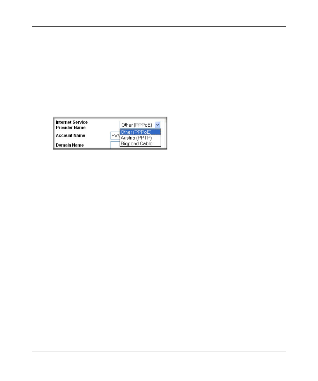
a. For connections that require a login using protocols such as PPPoE, PPTP, T elstra Bigpond
Cable broadband connections, select your Internet service provider from the drop-down
list.
Figure 3-11: Basic Settings ISP list
b.
The screen will change according to the ISP settings requirements of the ISP you select.
c. Fill in the parameters for your ISP according to the W izard-detected procedures starting on
page 3-11.
d. Click Apply to save your settings.
3-14 Connecting the Firewall to the Internet
January 2005
Page 39

Chapter 4
Firewall Protection and
Content Filtering
This chapter describes how to use the content filtering features of the FVS318v3 ProSafe VPN
Firewall to protect your network. These features can be found by clicking on the Security heading
in the main menu of the browser interface.
Firewall Protection and Content Filtering Overview
The FVS318v3 ProSafe VPN Firewall provides you with Web content filtering options, plus
browsing activity reporting and instant alerts via e-mail. Parents and network administrators can
establish restricted access policies based on time-of-day, Web addresses and Web address
keywords. You can also block Internet access by applications and services, such as chat or games.
A firewall is a special category of router that protects one network (the trusted network, such as
your LAN) from another (the untrusted network, such as the Internet), while allowing
communication between the two. A firewall incorporates the functions of a NAT (Network
Address Translation) router, while adding features for dealing with a hacker intrusion or attack,
and for controlling the types of traffic that can flow between the two networks. Unlike simple
Internet sharing NAT routers, a firewall uses a process called stateful packet inspection to protect
your network from attacks and intrusions. NAT performs a very limited stateful inspection in that
it considers whether the incoming packet is in response to an outgoing request, but true stateful
packet inspection goes far beyond NAT.
To configure these features of your firewall, click on the subheadings under the Security heading
in the main menu of the browser interface. The subheadings are described below:
Firewall Protection and Content Filtering 4-1
January 2005
Page 40

Reference Manual for the ProSafe VPN Firewall FVS318v3
Block Sites
The FVS318v3 allows you to restrict access based on Web addresses and Web address keywords.
Up to 255 entries are supported in the Keyword list. The Block Sites menu is shown in Figure 4-1:
Figure 4-1: Block Sites menu
To enable keyword blocking, check Turn keyword blocking on, then click Apply.
To add a keyword or domain, type it in the Keyword box, click Add Keyword, then click Apply.
To delete a keyword or domain, select it from the list, click Delete Keyword, then click Apply.
Keyword application examples:
• If the keyword "XXX" is specified, the URL <http://www.badstuff.com/xxx.html> is blocked,
as is the newsgroup alt.pictures.XXX.
• If the keyword “.com” is specified, only Web sites with other domain suffixes (such as .edu or
.gov) can be viewed.
• If you wish to block all Internet browsing access, enter the keyword “.”.
4-2 Firewall Protection and Content Filtering
January 2005
Page 41

Reference Manual for the ProSafe VPN Firewall FVS318v3
To spec ify a Trusted User, enter that PC’s IP address in the Trusted User box and click Apply.
You may specify one Trusted User, which is a PC that will be exempt from blocking and
logging. Since the Trusted User will be identified by an IP address, you should configure that
PC with a fixed or reserved IP address.
Using Rules to Block or Allow Specific Kinds of Traffic
Firewall rules are used to block or allow specific traffic passing through from one side to the other.
Inbound rules (WAN to LAN) restrict access by outsiders to private resources, selectively allowing
only specific outside users to access specific resources. Outbound rules (LAN to WAN) determine
what outside resources local users can have access to.
A firewall has two default rules, one for inbound traffic and one for outbound. The default rules of
the FVS318v3 are:
• Inbound: Block all access from outside except responses to requests from the LAN side.
• Outbound: Allow all access from the LAN side to the outside.
These default rules are shown in the Rules table of the Rules menu in Figure 4-2:
Figure 4-2: Rules menu
Firewall Protection and Content Filtering 4-3
January 2005
Page 42

Reference Manual for the ProSafe VPN Firewall FVS318v3
You may define additional rules that specify exceptions to the default rules. By adding custom
rules, you can block or allow access based on the service or application, source or destinat ion IP
addresses, and time of day. You can also choose to log traffic that matches or does not match the
rule you have defined.
To create a new rule, click the Add button.
To edit an existing rule, select its button on the left side of the table and click Edit.
To delete an existing rule, select its button on the left side of the table and click Delete.
To move an existing rule to a different position in the table, select its button on the left side of the
table and click Move. At the script prompt, enter the number of the desired new position and
click OK.
An example of the menu for defining or editing a rule is shown in Figure 4-3. The parameters are:
• Service. From this list, select the application or service to be allowed or blocked. The list
already displays many common services, but you are not limited to these choices. Use the
Services menu to add any additional services or applications that do not already appear.
• Action. Choose how you would like this type of traffic to be handled. You can block or allow
always, or you can choose to block or allow according to the schedule you have defined in the
Schedule menu.
• Source Address. Specify traffic originating on the LAN (outbound) or the WAN (inbound),
and choose whether you would like the traffic to be restricted by source IP address. You can
select Any, a Single address, or a Range. If you select a range of addresses, enter the range in
the start and finish boxes. If you select a single address, enter it in the start box.
• Destination Address.The Destination Address will be assumed to be from the opposite (LAN
or WAN) of the Source Address. As with the Source Address, you can select Any, a Single
address, or a Range unless NAT is enabled and the destination is the LAN. In that case, you
must enter a Single LAN address in the start box.
• Log. You can select whether the traffic will be logged. The choices are:
• Never — no log entries will be made for this service.
• Match — traffic of this type that matches the parameters and action will be logged.
4-4 Firewall Protection and Content Filtering
January 2005
Page 43

Reference Manual for the ProSafe VPN Firewall FVS318v3
Inbound Rules (Port Forwarding)
Because the FVS318v3 uses Network Address Translation (NAT), your network presents only one
IP address to the Internet, and outside users cannot directly address any of your local computers.
However, by defining an inbound rule you can make a local server (for example, a Web server or
game server) visible and available to the Internet. The rule tells the firewall to direct inbound
traffic for a particular service to one local server based on the destination port number. This is al so
known as port forwarding.
Note: Some residential broadband ISP accounts do not allow you to run any server
processes (such as a Web or FTP server) from your location. Your ISP may periodically
check for servers and may suspend your account if it discovers any active services at
your location. If you are unsure, refer to the Acceptable Use Policy of your ISP.
Remember that allowing inbound services opens holes in your FVS318v3 VPN Firewall. Only
enable those ports that are necessary for your network. Following are two application examples of
inbound rules:
Inbound Rule Example: A Local Public Web Server
If you host a public W eb ser ver on your local network, you can define a rule to allow inbound Web
(HTTP) requests from any outside IP address to the IP address of your Web server at any time of
day. This rule is shown in Figure 4-3:
Figure 4-3: Rule example: a local public Web server
Firewall Protection and Content Filtering 4-5
January 2005
Page 44

Reference Manual for the ProSafe VPN Firewall FVS318v3
Inbound Rule Example: Allowing a Videoconference from Restricted Addresses
If you want to allow incoming videoconferencing to be initiated from a restricted range of outside
IP addresses, such as from a branch office, you can create an inbound rule. In the example shown
in Figure 4-4, CU-SEEME connections are allowed only from a specified range of external IP
addresses. In this case, we have also specified logging of any incoming CU-SeeMe requests that
do not match the allowed parameters.
Figure 4-4: Rule example: a videoconference from rest rict ed ad d res se s
Considerations for Inbound Rules
• If your external IP address is assigned dynamically by your ISP, the IP address may change
periodically as the DHCP lease expires. Consider using the Dyamic DNS feature in the
Advanced menus so that external users can always find your network.
• If the IP address of the local server PC is assigned by DHCP, it may change when the PC is
rebooted. To avoid this, use the Reserved IP address feature in the LAN IP menu to keep the
PC’s IP address constant.
• Each local PC must access the local server using the PC’s local LAN address (192.168.0.99 in
this example). Attempts by local PCs to access the server using the external WAN IP address
will fail.
4-6 Firewall Protection and Content Filtering
January 2005
Page 45

Reference Manual for the ProSafe VPN Firewall FVS318v3
Outbound Rules (Service Blocking)
The FVS318v3 allows you to block the use of certain Internet services by PCs on your network.
This is called service blocking or port filtering. You can define an outbound rule to block Internet
access from a local PC based on:
• IP address of the local PC (source address)
• IP address of the Internet site being contacted (destination address)
•Time of day
• Type of servic e being requested (service port number)
Following is an application example of an outbound rule:
Outbound Rule Example: Blocking Instant Messenger
If you want to block Instant Messenger usage by employees during working hours, you can create
an outbound rule to block that application from any internal IP address to any external address
according to the schedule that you have created in the Schedule menu. You can also have the
firewall log any attempt to use Instant Messenger during that blocked period.
Figure 4-5: Rule example: blocking Instant Messenger
Firewall Protection and Content Filtering 4-7
January 2005
Page 46

Reference Manual for the ProSafe VPN Firewall FVS318v3
Order of Precedence for Rules
As you define new rules, they are added to the tables in the Rules table, as shown below:
Figure 4-6: Rules table with examples
For any traffic attempting to pass through the firewall, the packet information is subjected to the
rules in the order shown in the Rules table, beginning at the top and pr oceeding to th e default rules
at the bottom. In some cases, the order of precedence of two or more rules may be important in
determining the disposition of a packet. The Move button allows you to relocate a defined rule to a
new position in the table.
Default DMZ Server
Incoming traffic from the Internet is normally discarded by the firewall unless the traffic is a
response to one of your local computers or a service for which you have configured an inbound
rule. Instead of discarding this traffic, you can have it forwarded to one computer on your network.
This computer is called the Default DMZ Server.
4-8 Firewall Protection and Content Filtering
January 2005
Page 47

Reference Manual for the ProSafe VPN Firewall FVS318v3
The Default DMZ Server feature is helpful when using some online games and videoconferencing
applications that are incompatible with NAT. The firewall is programmed to recognize some of
these applications and to work properly with them, but there are other applications that may not
function well. In some cases, one local PC can run the application properly if that PC’s IP address
is entered as the Default DMZ Server.
Note: For security, NETGEAR strongly recommends that you avoid using the Default
DMZ Server feature. When a computer is designated as the Default DMZ Server, it loses
much of the protection of the firewall, and is exposed to many exploits from the Internet.
If compromised, the computer can be used to attack your network.
To assign a computer or server to be a Default DMZ server:
1. Click Default DMZ Server.
2. Type the IP address for that server.
3. Click Apply.
Note: In this application, the use of the term “DMZ ” has become common, although it is
a misnomer. In traditional firewalls, a DMZ is actually a separate physical network port.
A true DMZ port is for connecting servers that require greater access from the outside,
and will therefore be provided with a different level of security by the firewall. A better
term for our application is Exposed Host.
Respond to Ping on Internet WAN Port
If you want the firewall to respond to a ping from the Internet, click the Respond to Ping on
Internet WAN Port check box. This should only be used as a diagnostic tool, since it allows your
firewall to be discovered. Don't check this box unless you have a specific reason to do so.
Firewall Protection and Content Filtering 4-9
January 2005
Page 48

Reference Manual for the ProSafe VPN Firewall FVS318v3
Services
Services are functions performed by server computers at the request of client computers. For
example, Web servers serve Web pages, time servers serve time and date information, and game
hosts serve data about other players’ moves. When a computer on the Internet sends a request for
service to a server computer, the requested service is identified by a service or port number. This
number appears as the destination port number in the transmitted IP packets. For example, a packet
that is sent with destination port number 80 is an HTTP (Web server) request.
The service numbers for many common protocols are defined by the Internet Engineering Task
Force (IETF) and published in RFC1700, “Assigned Numbers.” Service numbers for other
applications are typically chosen from the range 1024 to 65535 by the authors of the application.
Although the FVS318v3 already holds a list of many service port numbers, you are not limited to
these choices. Use the Services menu to add additional services and applications to the list for use
in defining firewall rules. The Services menu shows a list of services that you have defined, as
shown in Figure 4-7:
Figure 4-7: Services menu
To define a new service, first you must determine which port number or range of n umbers is used
by the application. This information can usually be determined by contacting the publisher of the
application or from user groups of newsgroups.
4-10 Firewall Protection and Content Filtering
January 2005
Page 49

Reference Manual for the ProSafe VPN Firewall FVS318v3
To add a service:
1. When you have the port number information, go the Services menu and click on the Add
Custom Service button. The Add Services menu appears as shown in Figure 4-8:
Figure 4-8: Add Custom Service menu
2.
Enter a descriptive name for the service so that you will remember what it is.
3. Select whether the service uses TCP or UDP as its transport protocol.
If you can’t determine which is used, select both.
4. Enter the lowest port number used by the service.
5. Enter the highest port number used by the service.
If the service only uses a single port number, enter the same number in both fields.
6. Click Apply.
The new service now appears in the Services menu, and in the Service name selection box in the
Rules menu.
Firewall Protection and Content Filtering 4-11
January 2005
Page 50

Reference Manual for the ProSafe VPN Firewall FVS318v3
Using a Schedule to Block or Allow Specific Traffic
If you enabled content filtering in the Block Sites menu, or if you defined an outbound rule to use
a schedule, you can set up a schedule for when blocking occurs or when access is restricted. The
firewall allows you to specify when blocking will be enforced by configuring the Schedule page
shown below:
Figure 4-9: Schedule page
4-12 Firewall Protection and Content Filtering
January 2005
Page 51

Reference Manual for the ProSafe VPN Firewall FVS318v3
To block keywords or Internet domains based on a schedule, select Every Day o r select one or
more days. If you want to limit access completely for the selected days, select All Day. Otherwise,
If you want to limit access during certain times for the selected days, type a Start Blocking time
and an End Blocking time.
Note: Enter the values as 24-hour time. For example, to specify 10:30 am, enter 10 hours and 30
minutes; for 10:30 pm, enter 22 hours and 30 minutes.
Be sure to click Apply when you have finished configuring this page.
Time Zone
The FVS318v3 VPN Firewall uses the Network Time Protocol (NTP) to obtain the current time
and date from one of several Network Time Servers on the Internet. In order to localize the time
for your log entries, you must specify your Time Zone:
• Time Zone. Select your local time zone. This setting will be used for the blocking schedule
and for time-stamping log entries.
• Daylight Savings Time. Check this box for daylight savings time.
Note: If your region uses Daylight Savings Time, you must manually select Adjust for
Daylight Savings Time on the first day of Daylight Savings Time, and unselect it at the end.
Enabling Daylight Savings Time will add one hour to the standard time.
Be sure to click Apply when you have finished configuring this menu.
Firewall Protection and Content Filtering 4-13
January 2005
Page 52

Reference Manual for the ProSafe VPN Firewall FVS318v3
Getting E-Mail Notifications of Event Logs and Alerts
In order to receive logs and alerts by e-mail, you must provide yo ur e-mail information in the Send
alerts and logs by e-mail area:
Figure 4-10: E-mail menu
• Turn e-mail notification on. Check this box if you wish to receive e-mail logs and alerts from
the firewall.
• Send alerts and logs by e-mail. If your enable e-mail notification, these boxes cannot be
blank. Enter the name or IP address of your ISP’s outgoing (SMTP) mail server (such as
mail.myISP.com). You may be able to find this information in the configuration menu of your
e-mail program. Enter the e-mail address to which logs and alerts are sent. This e-mail address
will also be used as the From address. If you leave this box blank, log and alert messages will
not be sent via e-mail.
• Send E-mail alerts immediately. You can specify that logs are immediately sent to the
specified e-mail address when any of the following events occur:
– If a Denial of Service attack is detected.
– If a Port Scan is detected.
4-14 Firewall Protection and Content Filtering
January 2005
Page 53

Reference Manual for the ProSafe VPN Firewall FVS318v3
– If a user on your LAN attempts to access a W eb site that you blocked using the Block Sites
menu.
• Send logs according to this schedule. You can specify that logs are sent to you according to a
schedule. Select whether you would like to receive the logs None, Hourly, Daily, Weekly, or
When Full. Depending on your selection, you may also need to specify:
– Day for sending log
Relevant when the log is sent weekly or daily.
– Time for sending log
Relevant when the log is sent daily or weekly.
If the Weekly, Daily or Hourly option is selected and the log fills up before the specified
period, the log is automatically e-mailed to the specified e-mail address. After the log is sent,
the log is cleared from the firewall’s memory. If the firewall cannot e-mail the log file, the log
buffer may fill up. In this case, the firewall overwrites the log and discards its contents.
Be sure to click Apply when you have finished configuring this menu.
Firewall Protection and Content Filtering 4-15
January 2005
Page 54

Reference Manual for the ProSafe VPN Firewall FVS318v3
Viewing Logs of Web Access or Attempted Web Access
The firewall logs security-related events such as denied incoming and outgoing service requests,
hacker probes, and administrator logins. If you enable content filtering in the Block Sites menu,
the Log page will also show you when someone on your network tried to access a blocked site. If
you enabled e-mail notification, you'll receive these logs in an e-mail message. If you don't have
e-mail notification enabled, you can view the logs here. An example is shown in Figure 4-11:
Figure 4-11: Logs menu
4-16 Firewall Protection and Content Filtering
January 2005
Page 55

Reference Manual for the ProSafe VPN Firewall FVS318v3
Log entries are described in Table 4-1
Table 4-1. Log entry descriptions
Field Description
Date and Time The date and time the log entry was recorded.
Description or
Action
Source IP The IP address of the initiating device for this log entry.
Source port and
interface
Destination The name or IP address of the destination device or Web site.
Destination port and
interface
The type of event and what action was taken if any.
The service port number of the initiating device, and whether it
originated from the LAN or WAN.
The service port number of the destination device, and whether it’s on
the LAN or WAN.
Log action buttons are described in Table 4-2
Table 4-2. Log action buttons
Button Description
Refresh Refresh the log screen.
Clear Log Clear the log entries.
Send Log Email the log immediately.
Syslog
You can configure the firewall to send system logs to an external PC that is running a syslog
logging program. Enter the IP address of the logging PC and click the Enable Syslog check box.
Logging programs are available for Windows, Macintosh, and Linux computers.
Firewall Protection and Content Filtering 4-17
January 2005
Page 56

Reference Manual for the ProSafe VPN Firewall FVS318v3
4-18 Firewall Protection and Content Filtering
January 2005
Page 57

Chapter 5
Basic Virtual Private Networking
This chapter describes how to use the virtual private networking (VPN) features of the FVS318v3
VPN Firewall. VPN communications paths are called tunnels. VPN tunnels provide secure,
encrypted communications between your local network and a remote network or computer.
The VPN information is organized as follows:
• “Overview of VPN Configuration” on page 5-2 provides an overview of the two most
common VPN configurations: client-to-gateway and gateway-to-gateway.
• “Planning a VPN” on page 5-3 provides the VPN Committee (VPNC) recommended default
parameters set by the VPN Wizard.
• “VPN Tunnel Configuration” on page 5-5 summarizes the two ways to configure a VPN
tunnel: VPN Wizard (recommended for most situations) and Advanced (see Chapter 6,
“Advanced Virtual Private Networking).
• “How to Set Up a Client-to-Gateway VPN Configuration” on page 5-5 provides the steps
needed to configure a VPN tunnel between a remote PC and a network gateway using the VPN
Wizard and the NETGEAR ProSafe VPN Client.
• “How to Set Up a Gateway-to-Gateway VPN Configuration” on page 5-20 provides the steps
needed to configure a VPN tunnel between two network gateways using the VPN Wizard.
• “VPN Tunnel Control” on page 5-26 provides the step-by-step procedures for activating,
verifying, deactivating, and deleting a VPN tunnel once the VPN tunnel has been configured.
• Chapter 6, “Advanced Virtual Private Networking” provides the steps needed to configure
VPN tunnels when there are special circumstances and the VPNC recommended defaults of
the VPN Wizard are inappropriate.
• Appendix C, “Virtual Private Networking” discusses Virtual Private Networking (VPN)
Internet Protocol security (IPSec). IPSec is one of the most complete, secure, and
commercially available, standards-based protocols developed for transporting data.
• Appendix E, “VPN Configuration of NETGEAR FVS318v3” presents a case study on how to
configure a secure IPSec VPN tunnel from a NETGEAR FVS318v3 to a FVL328. This case
study follows the VPN Consortium interoperability profile guidelines (found at
http://www.vpnc.org/InteropProfiles/Interop-01.html).
Basic Virtual Private Networking 5-1
January 2005
Page 58

Reference Manual for the ProSafe VPN Firewall FVS318v3
Overview of VPN Configuration
T wo common scenarios for configuring VPN tunnels are between a remote personal computer an d
a network gateway and between two or more network gateways. The FVS318v3 supports both of
these types of VPN configurations. The FVS318v3 VPN Firewall supports up to eight concurrent
tunnels.
Client-to-Gateway VPN Tunnels
Client-to-gateway VPN tunnels provide secure access from a remote PC, such as a telecommuter
connecting to an office network (see Figure 5-1).
FVS318
VPN Tunnel
24.0.0.1
192.168.3.1
PCs
Figure 5-1: Client-to-gateway VPN tunnel
A VPN client access allows a remote PC to connect to your network from any location on the
Internet. In this case, the remote PC is one tunnel endpoint, running the VPN client software. The
FVS318v3 VPN Firewall on your network is the other tunnel endpoint. See “How to Set Up a
Client-to-Gateway VPN Configuration” on page 5-5 to set up this configuration.
Gateway-to-Gateway VPN Tunnels
• Gateway-to-gateway VPN tunnels provide secure access between networks, such as a branch
or home office and a main office (see Figure 5-2).
5-2 Basic Virtual Private Networking
January 2005
Page 59

Reference Manual for the ProSafe VPN Firewall FVS318v3
VPN Tunnel
VPN Gateway A
PCs
Figure 5-2: Gateway-to-gateway VPN tunnel
A VPN between two or more NETGEAR VPN-enabled firewalls is a good way to connect branch
or home offices and business partners over the Internet. VPN tunnels also enable access to network
resources across the Internet. In this case, use FVS318v3s on each end of the tunnel to form the
VPN tunnel end points. See “How to Set Up a Gateway-to-Gateway VPN Configuration” on page
5-20 to set up this configuration.
VPN Gateway B
PCs
Planning a VPN
To set up a VPN connection, you must configure each endpoint with specific identification and
connection information describing the other endpoint. You must configure the outbound VPN
settings on one end to match the inbound VPN settings on other end, and vice versa.
This set of configuration information defines a security association (SA) between the two VPN
endpoints. When planning your VPN, you must make a few choices first:
• Will the local end be any device on the LAN, a portion of the local network (as defined by a
subnet or by a range of IP addresses), or a single PC?
• Will the remote end be any device on the remote LAN, a portion of the remote network (as
defined by a subnet or by a range of IP addresses), or a single PC?
• Will either endpoint use Fully Qualified Domain Names (FQDNs)? Many DSL accounts are
provisioned with DHCP addressing, where the IP address of the WAN port can change from
time to time. Under these circumstances, configuring the WAN port with a dynamic DNS
(DynDNS) service provider simplifies the configuration task. When DynDNS is configured on
the WAN port, configure the VPN using FDQN.
Basic Virtual Private Networking 5-3
January 2005
Page 60

Reference Manual for the ProSafe VPN Firewall FVS318v3
FQDNs supplied by Dynamic DNS providers can allow a VPN endpoint with a dynamic IP
address to initiate or respond to a tunnel request. Otherwise, the side using a dynamic IP
address must always be the initiator.
• What method will you use to configure your VPN tunnels?
— The VPN Wizard using VPNC defaults (see Table 5-1)
— Advanced methods (see Chapter 6, “Advanced Virtual Private Networking”)
Table 5-1. Parameters recommended by the VPNC and used in the VPN Wizard
Parameter Factory Default
Secure Association Main Mode
Authentication Method Pre-shared Key
Encryption Method 3DES
Authentication Protocol SHA-1
Diffie-Hellman (DH) Group Group 2 (1024 bit)
Key Life 8 hours
IKE Life Time 24 hours
NETBIOS Enabled
• What level of IPSec VPN encryption will you use?
— DE — The Data Encryption Standard (DES) processes input data that is 64 bits wide,
encrypting these values using a 56 bit key. Faster but less secure than 3DES.
— 3DES — (Triple DES) achieves a higher level of security by encrypting the data three
times using DES with three different, unrelated keys.
—AES
• What level of authentication will you use?
— MDS — 128 bits, faster but less secure.
— SHA-1 — 160 bits, slower but more secure.
Note: NETGEAR publishes additional interoperability scenarios with various gateway
and client software products.
5-4 Basic Virtual Private Networking
January 2005
Page 61

Reference Manual for the ProSafe VPN Firewall FVS318v3
VPN Tunnel Configuration
There are two tunnel configurations and three ways to configure them:
• Use the VPN Wizard to configure a VPN tunnel (recommended for most situations):
— See “How to Set Up a Client-to-Gateway VPN Configuration” on page 5-5.
— See “How to Set Up a Gateway-to-Gateway VPN Configuration” on page 5-20.
• See Chapter 6, “Advanced Virtual Private Networking” when the VPN Wizard and its VPNC
defaults (see Table 5-1 on page 5-4) are not appropriate for your special circumstances.
How to Set Up a Client-to-Gateway VPN Configuration
Setting up a VPN between a remote PC running the NETGEAR ProSafe VPN Client and a
network gateway (see Figure 5-3) involves the following two steps:
• “Step 1: Configuring the Client-to-Gateway VPN Tunnel on the FVS318v3” on page 5-6 uses
the VPN Wizard to configure the VPN tunnel between the remote PC and network gateway.
• “Step 2: Configuring the NETGEAR ProSafe VPN Client on the Remote PC” on page 5-9
configures the NETGEAR ProSafe VPN Client endpoint.
FVS318v3
VPN Tunnel
24.0.0.1
192.168.3.1
PCs
Figure 5-3: Client-to-gateway VPN tunnel
Basic Virtual Private Networking 5-5
PC
(Running NETGEAR
ProSafe VPN Client)
January 2005
Page 62

Reference Manual for the ProSafe VPN Firewall FVS318v3
Step 1: Configuring the Client-to-Gateway VPN Tunnel on the FVS318v3
Note: This section uses the VPN Wizard to set up the VPN tunnel using the VPNC
default parameters listed in Table 5-1 on page 5-4. If you have special requirements not
covered by these VPNC-recommended parameters, refer to Chapter 6, “Advanced
V irtual Private Networking” to set up the VPN tunnel.
Follow this procedure to configure a client-to-gateway VPN tunnel using the VPN Wizard.
1. Log in to the FVS318v3 at its LAN address of http://192.168.0.1 with its default user name of
admin and password of password. Click the VPN Wizard link in the main menu to display
this screen. Click Next to proceed.
Figure 5-4: VPN Wizard start screen
2.
Fill in the Connection Name and the pre-shared key, select the type of target end point, and
click Next to proceed.
Note: The Connection Name is arbitrary and not relevant to how the configuration functions.
5-6 Basic Virtual Private Networking
January 2005
Page 63

Reference Manual for the ProSafe VPN Firewall FVS318v3
Enter the new Connection Name:
(RoadWarrior in this example)
Enter the pre-shared key:
(12345678 in this example)
Select the radio button:
A remote VPN client (single PC)
Figure 5-5: Connection Name and Remote IP Type
The Summary screen below displays.
Figure 5-6: VPN Wizard Summary
Basic Virtual Private Networking 5-7
January 2005
Page 64

Reference Manual for the ProSafe VPN Firewall FVS318v3
To view the VPNC recommended authentication and encryptio n settings used by the VPN
Wizard, click the here link (see Figure 5-6). Click Back to return to the Summary screen.
Figure 5-7: VPNC Recommended Settings
Click Done on the Summary screen (see Figure 5-6) to complete the configuration procedure.
3.
The VPN Policies menu below displays showing that the new tunnel is enabled.
Figure 5-8: VPN Policies
T o view or modify the tunnel settings, select the radio button next to the tunnel entry and click
Edit.
5-8 Basic Virtual Private Networking
January 2005
Page 65

Reference Manual for the ProSafe VPN Firewall FVS318v3
Step 2: Configuring the NETGEAR ProSafe VPN Client on the Remote PC
This procedure describes how to configure the NETGEAR ProSafe VPN Client. This example
assumes the PC running the client has a dynamically assigned IP address.
The PC must have the NETGEAR ProSafe VPN Client program installed that supports IPSec. Go
to the NETGEAR Web site (http://www.netgear.com) and select VPN01L_VPN05L in the Product
Quick Find drop-down menu for information on how to purchase the NETGEAR ProSafe VPN
Client.
Note: Before installing the NETGEAR ProSafe VPN Client software, be sure to turn off
any virus protection or firewall software you may be running on your PC.
1. Install the NETGEAR ProSafe VPN Client on the remote PC and reboot.
a. You may need to insert your Windows CD to complete the installation.
b. If you do not have a modem or dial-up adapter installed in your PC, you may see the
warning message stating “The NETGEAR ProSafe VPN Component requires at least one
dial-up adapter be installed.” You can disregard this message.
c. Install the IPSec Component. You may have the option to install either the VPN Adapter
or the IPSec Component or both. The VPN Adapter is not necessary.
d. The system should show the ProSafe icon ( ) in the system tray after rebooting.
e. Double-click the system tray icon to open the Security Policy Editor.
2. Add a new connection.
Note: The procedure in this section explains how to create a new security policy from
scratch. For the procedure on how to import an existing security policy that has already
been created on another client running the NETGEAR ProSafe VPN Client, see
“Transferring a Security Policy to Another Client” on page 5-18.
a. Run the NETGEAR ProSafe Security Policy Editor program and create a VPN
Connection.
Basic Virtual Private Networking 5-9
January 2005
Page 66

Reference Manual for the ProSafe VPN Firewall FVS318v3
From the Edit menu of the Security Policy Editor, click Add, then Connection. A “New
b.
Connection” listing appears in the list of policies. Rename the “New Connection” so that it
matches the Connection Name you entered in the VPN Settings of the FVS318v3 on
LAN A.
Note: In this example, the Connection Name used on the client side of the VPN tunnel is
NETGEAR_VPN_router and it does not have to match the RoadWarrior Connection
Name used on the gateway side of the VPN tunnel (see Figure 5-5) because Connection
Names are unrelated to how the VPN tunnel functions.
Tip: Choose Connection Names that make sense to the people using and administrating
the VPN.
Figure 5-9: Security Policy Editor new connection
5-10 Basic Virtual Private Networking
January 2005
Page 67

Reference Manual for the ProSafe VPN Firewall FVS318v3
Figure 5-10: Security Policy Editor connection settings
c.
Select Secure in the Connection Security check box.
d. Select IP Subnet in the ID Type menu.
In this example, type 192.168.3.1 in the Subnet field as the network address of the
FVS318v3.
e. Enter 255.255.255.0 in the Mask field as the LAN Subnet Mask of the FVS318v3.
f. Select All in the Protocol menu to allow all traffic through the VPN tunnel.
g. Select the Connect using Secure Gateway Tunnel check box.
h. Select IP Address in the ID Type menu below the check box.
i. Enter the public WAN IP Address of the FVS318v3 in the field directly below the ID Type
menu. In this example,
22.23.24.25 would be used.
The resulting Connection Settings are shown in Figure 5-10.
3. Configure the Security Policy in the NETGEAR ProSafe VPN Client software.
a. In the Network Security Policy list, expand the new connection by double clicking its
name or clicking on the “+” symbol. My Identity and Security Policy subheadings appear
below the connection name.
b. Click on the Security Policy subheading to show the Security P olicy menu.
Basic Virtual Private Networking 5-11
January 2005
Page 68

Reference Manual for the ProSafe VPN Firewall FVS318v3
Figure 5-11: Security Policy Editor Security Policy
c.
Select the Main Mode in the Select Phase 1 Negotiation Mode check box.
4. Configure the VPN Client Identity.
In this step, you will provide information about the remote VPN client PC. You will need to
provide:
— The Pre-Shared Key that you configured in the FVS318v3.
— Either a fixed IP address or a “fixed virtual” IP address of the VPN client PC.
a. In the Network Security Policy list on the left side of the Security Policy Editor window,
click on My Identity.
5-12 Basic Virtual Private Networking
January 2005
Page 69

Reference Manual for the ProSafe VPN Firewall FVS318v3
Figure 5-12: Security Policy Editor My Identity
b.
Choose None in the Select Certificate box.
c. Select IP Address in the ID Type box. If you are using a virtual fixed IP address, enter this
address in the Internal Network IP Address box. Otherwise, leave this box empty.
d. In the Internet Interface box, select the adapter you use to access the Internet. Select PPP
Adapter in the Name menu if you have a dial-up Internet account. Select your Ethernet
adapter if you have a dedicated Cable or DSL line. You may also choose Any if you will
be switching between adapters or if you have only one adapter.
e. Click the Pre-Shared Key button. In the Pre-Shared Key dialog box, click the Enter Key
button. Enter the FVS318v3's Pre-Shared Key and click OK. In this example, 12345678 is
entered. This field is case sensitive.
Figure 5-13: Security Policy Editor Pre-Shared Key
Basic Virtual Private Networking 5-13
January 2005
Page 70

Reference Manual for the ProSafe VPN Firewall FVS318v3
Configure the VPN Client Authentication Proposal.
5.
In this step, you will provide the type of encryption (DES or 3DES) to be used for this
connection. This selection must match your selection in the FVS318v3 configuration.
a. In the Network Security Policy list on the left side of the Security Policy Editor window,
expand the Security Policy heading by double clicking its name or clicking on the “+”
symbol.
b. Expand the Authen tication subheading by double clicking its name or clicking on the “+”
symbol. Then select Proposal 1 below Authentication.
Figure 5-14: Security Policy Editor Authentication
In the Authentication Method menu, select Pre-Shared key.
c.
d. In the Encrypt Alg menu, select the type of encryption. In this example, use Triple DES.
e. In the Hash Alg menu, select SHA-1.
f. In the SA Life menu, select Unspecified.
g. In the Key Group menu, select Diffie-Hellman Group 2.
6. Configure the VPN Client Key Exchange Proposal.
In this step, you will provide the type of encryption (DES or 3DES) to be used for this
connection. This selection must match your selection in the FVS318v3 configuration.
a. Expand the Key Exchange subheading by double clicking its name or clicking on the “+”
symbol. Then select Proposal 1 below Key Exchange.
5-14 Basic Virtual Private Networking
January 2005
Page 71

Reference Manual for the ProSafe VPN Firewall FVS318v3
Figure 5-15: Security Policy Editor Key Exchange
b.
In the SA Life menu, select Unspecified.
c. In the Compression menu, select None.
d. Check the Encapsulation Protocol (ESP) check box.
e. In the Encrypt Alg menu, select the type of encryption. In this example, use Triple DES.
f. In the Hash Alg menu, select SHA-1.
g. In the Encapsulation menu, select Tunnel.
h. Leave the Authentication Protocol (AH) check box unchecked.
7. Save the VPN Client Settings.
From the File menu at the top of the Security Policy Editor window, select Save.
After you have configured and saved the VPN client information, your PC will automatically
open the VPN connection when you attempt to access any IP addresses in the range of the
remote VPN firewall’s LAN.
8. Check the VPN Connection.
To check the VPN Connection, you can initiate a request from the remote PC to the
FVS318v3’ s network by using the “Connect” op tion in the NETGEAR ProSafe menu bar. The
NETGEAR ProSafe client will report the results of the attempt to connect. Since the remote
PC has a dynamically assigned WAN IP address, it must initiate the request.
To perform a ping tes t using our example, start from the remote PC:
Basic Virtual Private Networking 5-15
January 2005
Page 72

Reference Manual for the ProSafe VPN Firewall FVS318v3
Establish an Internet connection from the PC.
a.
b. On the Windows taskbar, click the Start button, and then click Run.
c. Type ping -t 192.168.3.1 , and then click OK.
Figure 5-16: Running a Ping test to the LAN from the PC
This will cause a continuous ping to be sent to the first FVS318v3. After between several
seconds and two minutes, the ping response should change from “timed out” to “reply.”
Figure 5-17: Ping test results
Once the connection is established, you can open the browser of the PC and enter the LAN IP
address of the remote FVS318v3. After a short wait, you should see the login screen of the VPN
Firewall (unless another PC already has the FVS318v3 management interface open).
Monitoring the Progress and Status of the VPN Clie nt Connection
Information on the progress and status of the VPN client connection can be viewed by opening the
NETGEAR ProSafe Log Viewer.
1. To launch this function, click on the Windows Start button, then select Programs, then
NETGEAR ProSafe VPN Client, then Log Viewer.
5-16 Basic Virtual Private Networking
January 2005
Page 73
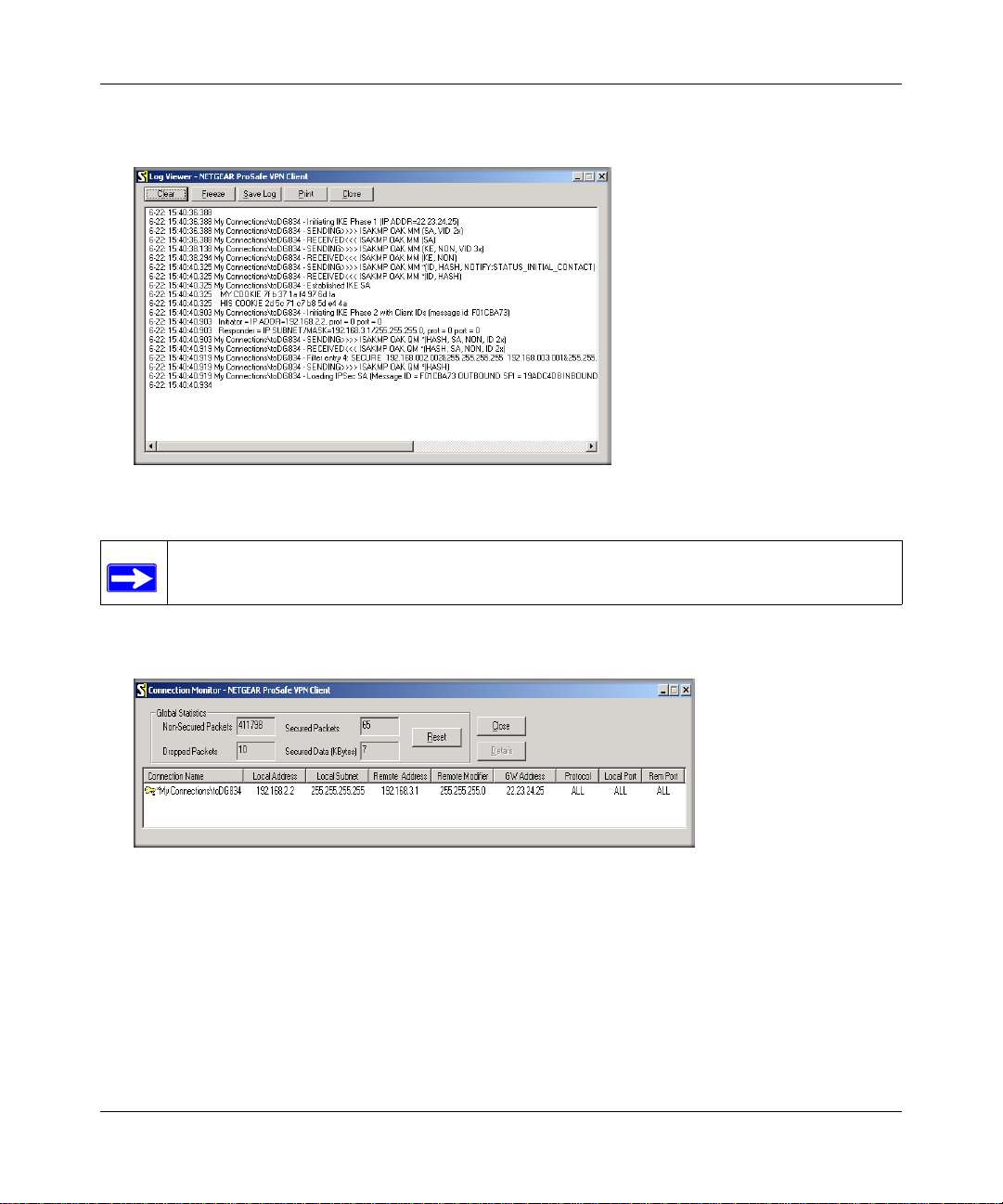
Reference Manual for the ProSafe VPN Firewall FVS318v3
The Log Viewer screen for a similar successful connection is shown below:
Figure 5-18: Log Viewer screen
Note: Use the active VPN tunnel information and pings to determine whether a failed
connection is due to the VPN tunnel or some reason outside the VPN tunnel.
2.
The Connection Monitor screen for a similar connection is shown below:
Figure 5-19: Connection Monitor screen
In this example you can see the following:
• The FVS318v3 has a public IP WAN address of 22.23.24.25.
• The FVS318v3 has a LAN IP address of 192.168.3.1.
• The VPN client PC has a dynamically assigned address of 192.168.2.2.
Basic Virtual Private Networking 5-17
January 2005
Page 74

Reference Manual for the ProSafe VPN Firewall FVS318v3
While the connection is being established, the Connection Name field in this menu will say “SA”
before the name of the connection. When the connection is successful, the “SA” will change to the
yellow key symbol shown in the illustration above.
Note: While your PC is co nnected to a remote LAN through a VPN, you might not have
normal Internet access. If this is the case, you will need to close the VPN connection in
order to have normal Internet access.
Transferring a Security Policy to Another Client
This section explains how to export and import a security policy as an .spd file so that an existing
NETGEAR ProSafe VPN Client configuration can be copied to other PCs running the NETGEAR
ProSafe VPN Client.
Exporting a Security Policy
The following procedure (Figure 5-20) enables you to export a security policy as an .spd file.
Step 1: Select Export Security Policy from
the File pulldown.
Step 2: Click Export once you decide the name of the file
and directory where you want to store the client policy.
In this example, the exported policy is named policy.spd
and is being stored on the C drive.
Figure 5-20: Exporting a security policy
5-18 Basic Virtual Private Networking
January 2005
Page 75

Reference Manual for the ProSafe VPN Firewall FVS318v3
Importing a Security Policy
The following procedure (Figure 5-21) enables you to import an existing security policy.
Step 1: Invoke the NETGEAR ProSafe
VPN Client and select Import Security
Policy from the File pulldown.
Step 2: Select the security policy to import.
In this example, the security policy file is
named FVS318v3_clientpolicy_direct.spd
and located on the Desktop.
The security policy is now imported.
In this example, the connection name is
Scenario_1.
Figure 5-21: Importing a security policy
Basic Virtual Private Networking 5-19
January 2005
Page 76

Reference Manual for the ProSafe VPN Firewall FVS318v3
How to Set Up a Gateway-to-Gateway VPN Configuration
Note: This section uses the VPN Wizard to set up the VPN tunnel using the VPNC
default parameters listed in Table 5-1 on page 5-4. If you have special requirements not
covered by these VPNC-recommended parameters, refer to Chapter 6, “Advanced
V irtual Private Networking” to set up the VPN tunnel.
VPN Tunnel
A
FVS318v3 VPN Firewall
B
FVS318v3 VPN Firewall
PCs
Figure 5-22: Gateway-to-Gateway VPN Tunnel
Follow the procedure below to set the LAN IPs on each FVS318v3 to different subnets and
configure each properly for the Internet.
The LAN IP address ranges of each VPN endpoint must be different. The connection will fail if
both are using the NETGEAR default address range of 192.168.0.x.
In this example, LAN A uses 192.168.0.1 and LAN B uses 192.168.3.1.
PCs
5-20 Basic Virtual Private Networking
January 2005
Page 77

Reference Manual for the ProSafe VPN Firewall FVS318v3
Procedure to Configure a Gateway-to-Gateway VPN Tunnel
Follow this procedure to configure a gateway-to-gateway VPN tunnel using the VPN Wizard.
1. Log in to the FVS318v3 on LAN A at its default LAN address of http://192.168.0.1 with its
default user name of
main menu to display this screen. Click Next to proceed.
Figure 5-23: VPN Wizard start screen
admin and password of password. Click the VPN Wizard link in the
2.
Fill in the Connection Name and the pre-shared key, select the type of target end point, and
click Next to proceed.
Enter the new Connection Name:
(GtoG in this example)
Enter the pre-shared key:
(12345678 in this example)
Select the radio button:
A remote VPN Gateway
Figure 5-24: Connection Name and Remote IP Type
Basic Virtual Private Networking 5-21
January 2005
Page 78

Reference Manual for the ProSafe VPN Firewall FVS318v3
3. Fill in the IP Address or FQDN for the target VPN endpoint WAN connection and click Next.
Enter the WAN IP address of the remote VPN
gateway:
(22.23.24.25 in this example)
Figure 5-25: Remote IP
4. Identify the IP addresses at the target endpoint that can use this tunnel, and click Next.
Enter the LAN IP settings of the remote VPN
gateway:
• IP Address
(192.168.3.1 in this example)
• Subnet Mask
(255.255.255.0 in this example)
Figure 5-26: Secure Connection Remote Accessibility
5-22 Basic Virtual Private Networking
January 2005
Page 79

Reference Manual for the ProSafe VPN Firewall FVS318v3
The Summary screen below displays.
Figure 5-27: VPN Wizard Summary
Basic Virtual Private Networking 5-23
January 2005
Page 80

Reference Manual for the ProSafe VPN Firewall FVS318v3
To view the VPNC recommended authentication and encryptio n settings used by the VPN
Wizard, click the here link (see Figure 5-27). Click Back to return to the Summary screen.
Figure 5-28: VPN Recommended Settings
Click Done on the Summary screen (see Figure 5-27) to complete the configuration
5.
procedure. The VPN Policies menu below displays showing that the new tunnel is enabled.
Figure 5-29: VPN Policies
5-24 Basic Virtual Private Networking
January 2005
Page 81

Reference Manual for the ProSafe VPN Firewall FVS318v3
Repeat for the FVS318v3 on LAN B. Pay special attention and use the following network
6.
settings as appropriate.
• WAN IP of the remote VPN gateway (e.g., 14.15.16.17)
• LAN IP settings of the remote VPN gateway:
— IP Address (e.g, 192.168.0.1)
— Subnet Mask (e.g., 255.255.255.0)
— Preshared Key (e.g., 12345678)
7. Use the VPN Status screen to activate the VPN tunnel by performing the following steps:
Note: The VPN Status screen is only one of three ways to active a VPN tunnel. See
“Activating a VPN Tunnel” on page 5-26 for information on the other ways.
a. Open the FVS318v3 management interface and click on VPN Status under VPN to get the
VPN Status/Log screen (Figure 5-30).
Figure 5-30: VPN Status/Log screen
Click on VPN Status (Figure 5-32) to get the Current VPN Tu nnels (SAs) screen
b.
(Figure 5-31). Click on Connect for the VPN tunnel you want to activate.
Basic Virtual Private Networking 5-25
January 2005
Page 82
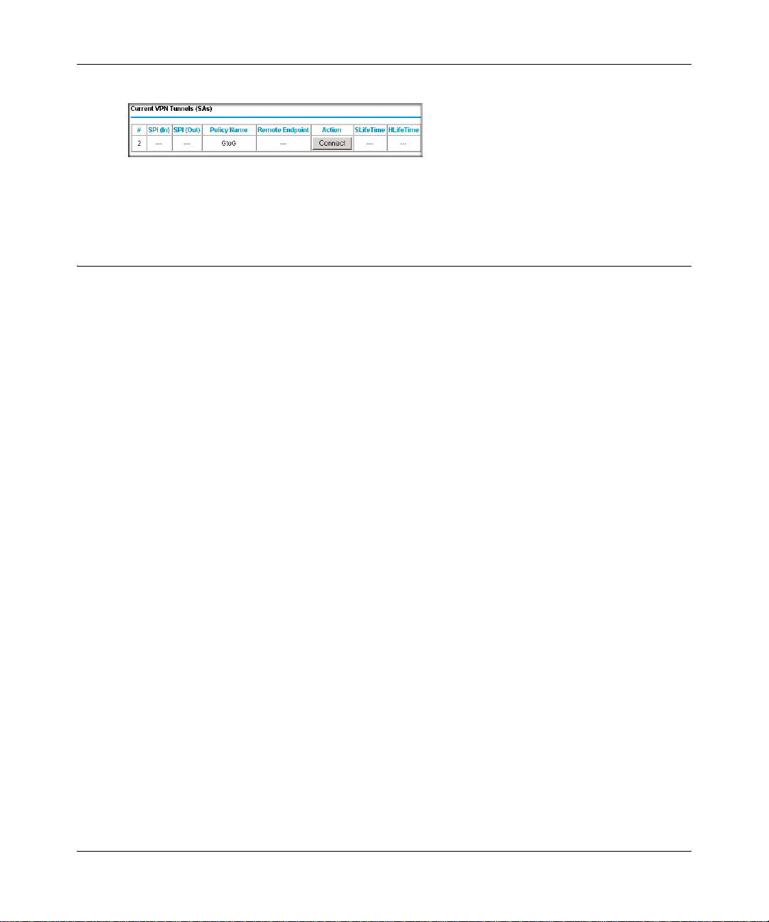
Reference Manual for the ProSafe VPN Firewall FVS318v3
Figure 5-31: Current VPN Tunnels (SAs) Screen
c.
Look at the VPN Status/Log screen (Figure 5-30) to verify that the tunnel is connected.
VPN Tunnel Control
Activating a VPN Tunnel
There are three ways to activate a VPN tunnel:
• Start using the VPN tunnel.
• Use the VPN Status page.
• Activate the VPN tunnel by pinging the remote endpoint.
Start Using a VPN Tunnel to Activate It
To use a VPN tunnel, use a Web browser to go to a URL whose IP address or range is covered by
the policy for that VPN tunnel.
Using the VPN Status Page to Activate a VPN Tunnel
To use the VPN Status screen to activate a VPN tunnel, perform the following steps:
1. Log in to the VPN Firewall.
2. Open the FVS318v3 management interface and click on VPN Status under VPN to get the
VPN Status/Log screen (Figure 5-32).
5-26 Basic Virtual Private Networking
January 2005
Page 83

Reference Manual for the ProSafe VPN Firewall FVS318v3
Figure 5-32: VPN Status/Log screen
3.
Click VPN Status (Figure 5-32) to get the Current VPN Tunnels (SAs) screen (Figu re 5-3 3).
Click Connect for the VPN tunnel you want to activate.
Figure 5-33: Current VPN Tunnels (SAs) screen
Activate the VPN Tunnel by Pinging the Remote Endpoint
Note: This section uses 192.168.3.1 for an example remote endpoint LAN IP address.
To activate the VPN tunnel by pinging the remote endpoint (192.168.3.1), do the following steps
depending on whether your configuration is client-to-gateway or gateway-to-gateway:
• Client-to-Gateway Configuration—to check the VPN Connection, you can initiate a request
from the remote PC to the FVS318v3’s network by using the “Connect” option in the
NETGEAR ProSafe menu bar. The NETGEAR ProSafe client will report the results of the
attempt to connect. Since the remote PC has a dynamically assigned WAN IP address, it must
initiate the request.
To perform a ping tes t using our example, start from the remote PC:
Basic Virtual Private Networking 5-27
January 2005
Page 84

Reference Manual for the ProSafe VPN Firewall FVS318v3
Establish an Internet connection from the PC.
a.
b. On the Windows taskbar, click the Start button, and then click Run.
c. Type ping -t 192.168.3.1 and then click OK.
Figure 5-34: Running a Ping test to the LAN from the PC
This will cause a continuous ping to be sent to the first FVS318v3. Within two minutes,
the ping response should change from “timed out” to “reply.”
Note: Use Ctrl-C to stop the pinging.
Figure 5-35: Ping test results
Once the connection is established, you can open the browser of the PC and enter the LAN IP
address of the remote FVS318v3. After a short wait, you should see the login screen of the
VPN Firewall (unless another PC already has the FVS318v3 management interface open).
• Gateway-to-Gateway Configuration—test the VPN tunnel by pinging the remote network
from a PC attached to the FVS318v3.
a. Open a command prompt (Start -> Run -> cmd).
b. Type ping 192.168.3.1.
5-28 Basic Virtual Private Networking
January 2005
Page 85

Reference Manual for the ProSafe VPN Firewall FVS318v3
Figure 5-36: Pinging test results
Note: The pings may fail the first time. If so, then try the pings a second time.
Verifying the Status of a VPN Tunnel
To use the VPN Status page to determine the status of a VPN tunnel, perform the following steps:
1. Log in to the VPN Firewall.
2. Open the FVS318v3 management interface and click VPN Status under VPN to get the VPN
Status/Log screen (Figure 5-37).
Figure 5-37: VPN Status/Log screen
Log—this log shows the details of recent VPN activity, including the building of the VPN
tunnel. If there is a problem with the VPN tunnel, refer to the log for information about what
might be the cause of the problem.
• Click Refresh to see the most recent entries.
Basic Virtual Private Networking 5-29
January 2005
Page 86

Reference Manual for the ProSafe VPN Firewall FVS318v3
• Click Clear Log to delete all log entries.
3. Click VP N Status (Figure 5-37) to get the Current VPN Tunnels (SAs) screen (Figure 5-38).
Figure 5-38: Current VPN Tunnels (SAs) screen
This page lists the following data for each active VPN Tunnel.
• SPI—each SA has a unique SPI (Security Parameter Index) for traffic in each direction.
For Manual key exchange, the SPI is specified in the Policy definition. For Automatic key
exchange, the SPI is generated by the IKE protocol.
• Policy Name—the name of the VPN policy associated with this SA.
• Remote Endpoint—the IP address on the remote VPN Endpoint.
• Action—the action will be either a Drop or a Connect button.
• SLifeTime (Secs)—the remaining Soft Lifetime for this SA in seconds. When the Soft
Lifetime becomes zero, the SA (Security Association) will re-negotiated.
• HLifeTime (Secs)—the remaining Hard Lifetime for this SA in seconds. When the Hard
Lifetime becomes zero, the SA (Security Association) will be terminated. (It will be
re-established if required.)
Deactivating a VPN Tunnel
Sometimes a VPN tunnel must be deactivated for testing purposes. There are two ways to
deactivate a VPN tunnel:
• Policy table on VPN Policies page
• VPN Status page
Using the Policy Table on the VPN Policies Page to Deactivate a VPN Tunnel
To use the VPN Policies page to deactivate a VPN tunnel, perform the following steps:
1. Log in to the VPN Firewall.
2. Click on VPN Policies under VPN to get the VPN Policies screen below (Figure 5-39).
5-30 Basic Virtual Private Networking
January 2005
Page 87
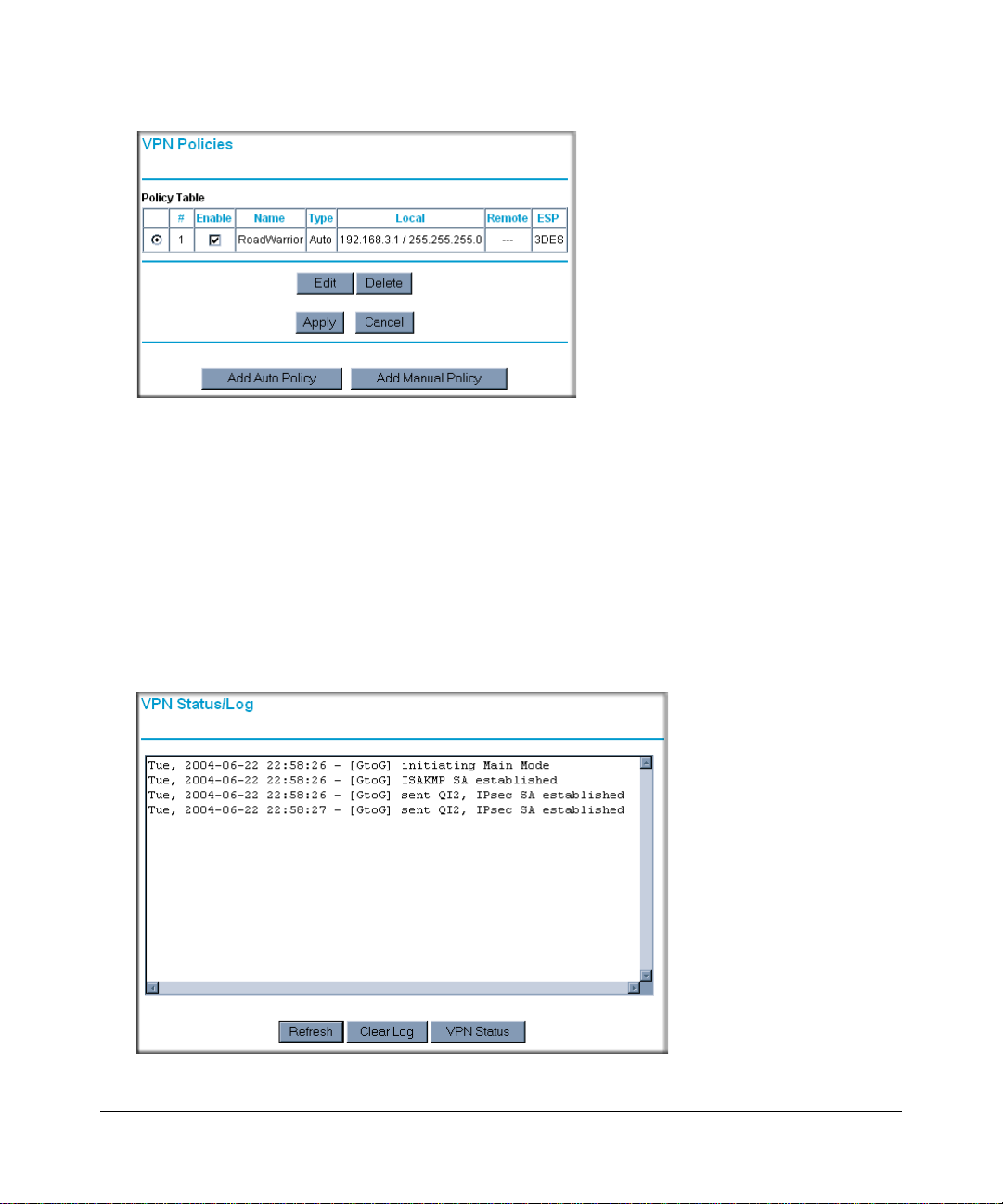
Reference Manual for the ProSafe VPN Firewall FVS318v3
Figure 5-39: VPN Policies
Clear the Enable check box for the VPN tunnel you want to deactivate and click Apply. (To
3.
reactivate the tunnel, check the Enable box and click Apply.)
Using the VPN Status Page to Deactivate a VPN Tunnel
To use the VPN Status page to deactivate a VPN tunnel , perform the following steps:
1. Log in to the VPN Firewall.
2. Click VP N Status under VPN to get the VPN Status/Log screen (Figure 5-40).
Figure 5-40: VPN Status/Log screen
Basic Virtual Private Networking 5-31
January 2005
Page 88
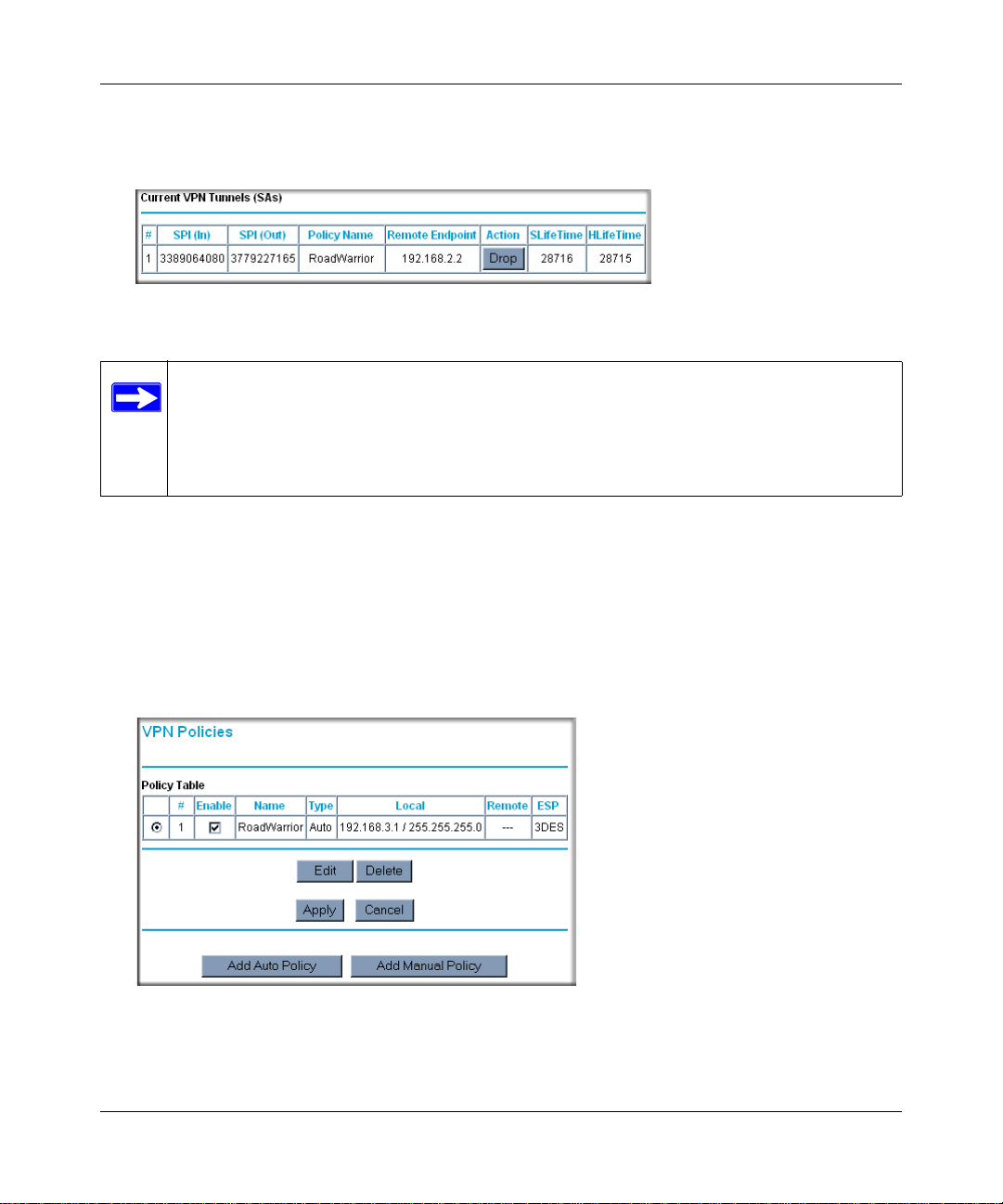
Reference Manual for the ProSafe VPN Firewall FVS318v3
Click VPN Status (Figure 5-40) to get the Current VPN Tunnels (SAs) screen (Figu re 5-4 1).
3.
Click Drop for the VPN tunnel you want to deactivate.
Figure 5-41: Current VPN Tunnels (SAs) screen
Note: When NETBIOS is enabled (which it is in the VPNC defaults implemented by
the VPN Wizard), automatic traffic will reactivate the tunnel. To prevent reactivation
from happening, either disable NETBIOS or disable the policy for the tunnel (see
“Using the Policy T able on the VPN Policies Page to Deactivate a VPN T unnel” on page
5-30).
Deleting a VPN Tunnel
To delete a VPN tunnel:
1. Log in to the VPN Firewall.
2. Click VP N Policies under VPN to display the VPN Policies screen (Figure 5-42). Select the
radio button for the VPN tunnel to be deleted and click the Delete button.
Figure 5-42: VPN Policies
5-32 Basic Virtual Private Networking
January 2005
Page 89

Chapter 6
Advanced Virtual Private Networking
This chapter describes how to use the advanced virtual private networking (VPN) features of the
FVS318v3 VPN Firewall. See Chapter 5, “Basic Virtual Private Networking” for a description on
how to use the basic VPN features.
Overview of FVS318v3 Policy-Based VPN Configuration
The FVS318v3 uses state-of-the-art firewall and security technology to facilitate controlled and
actively monitored VPN connectivity . Since the FVS318v3 strictly conforms to IETF standards, it
is interoperable with devices from major network equipment vendors.
FVS318v3 VPN Firewall
PCs
Figure 6-1: Secure access through FVS318v3 VPN firewalls
Advanced Virtual Private Networking 6-1
January 2005
FVS318v3 VPN Firewall
PCs
Page 90

Reference Manual for the ProSafe VPN Firewall FVS318v3
Using Policies to Manage VPN Traffic
You create policy definitions to manage VPN traffic on the FVS318v3. There are two kinds of
policies:
• IKE Policies: Define the authentication scheme and automatically generate the encryption
keys. As an alternative option, to further automate the process, you can create an IKE policy
that uses a trusted certificate authority to provide the authentication while the IKE policy still
handles the encryption.
• VPN Policies: Apply the IKE policy to specific traffic that requires a VPN tunnel. Or, you can
create a VPN policy that does not use an IKE policy but in which you manually enter all the
authentication and key parameters.
Since VPN policies use IKE policies, you define the IKE policy first. The FVS318v3 also allows
you to manually input the authentication scheme and encryption key values. In the case of manual
key management there will not be any IKE policies.
In order to establish secure communication over the Internet with the remote site you need to
configure matching VPN policies on both the local and remote FVS318v3 VPN Firewalls. The
outbound VPN policy on one end must match to the inbound VPN policy on oth er end, and vice
versa.
When the network traffic enters into the FVS318v3 from the LAN network interface, if there is no
VPN policy found for a type of network traffic, then that traffic passes through without any
change. However, if the traffic is selected by a VPN policy, then the IPSec authentication and
encryption rules are applied to it as defined in the VPN policy.
By default, a new VPN policy is added with the least priority, that is, at the end of the VPN policy
table.
Using Automatic Key Management
The most common configuration scenarios will use IKE policies to automatically manage the
authentication and encryption keys. Based on the IKE policy, so me parameters for the VPN tunnel
are generated automatically. The IKE protocols perform negotiations between the two VPN
endpoints to automatically generate required parameters.
Some organizations will use an IKE policy with a Certificate Authority (CA) to perform
authentication. Typically, CA authentication is used in large organizations that maintain their own
internal CA server. This requires that each VPN gateway have a certificate from the CA. Using
CAs reduces the amount of data entry required on each VPN endpoint.
6-2 Advanced Virtual Private Networking
January 2005
Page 91

Reference Manual for the ProSafe VPN Firewall FVS318v3
IKE Policies’ Automatic Key and Authentication Management
Click the IKE Policies link from the VPN section of the main menu, and then click the Add button
of the IKE Policies screen to display the IKE Policy Configuration menu shown in Figure 6-2.
Figure 6-2: IKE - Policy Configuration Menu
Advanced Virtual Private Networking 6-3
January 2005
Page 92

Reference Manual for the ProSafe VPN Firewall FVS318v3
The IKE Policy Configuration fields are defined in the following table.
Table 6-1. IKE Policy Configuration fields
Field Description
General These settings identify this policy and determine its major characteristics.
Policy Name The descriptive name of the IKE policy. Each policy should have a unique
policy name. This name is not supplied to the remote VPN endpoint. It is
only used to help you identify IKE policies.
Direction/Type This setting is used when determining if the IKE policy matches the current
traffic. The drop-down menu includes the following:
• Initiator — Outgoing connections are allowed, but incoming are blocked.
• Responder — Incoming connections are allowed, bu t outgoing are
blocked.
• Both Directions — Both outgoing and incoming connections are allowed.
• Remote Access — This is to allow only incoming client connections,
where the IP address of the remote clie n t is un known.
If Remote Access is selected, the Exchange Mode must be Aggressive,
and the Identities below (both Local and Remote) must be Name. On the
matching VPN Policy, the IP address of the remote VPN endpoint should
be set to 0.0.0.0.
Exchange Mode Main Mode or Aggressive Mode. This setting must match the setting used
on the remote VPN endpoint.
• Main Mode is slower but more secure. Also, the Identity below must be
established by IP address.
• Aggressive Mode is faster but less secure. The Identity below can be by
name (host name, domain name, and e-mail address) instead of by IP
address.
Local These parameters apply to the Local FVS318v3 VPN Firewall.
Local Identity Type Use this field to identify the local FVS318v3. You can choose one of the
following four options from the drop-down list:
• By its Internet (WAN) port IP address.
• By its Fully Qualified Domain Name (FQDN) — your domain name.
• By a Fully Qualified User Name — your name, E-mail address, or
other ID.
• By DER ASN.1 DN — the binary DER encoding of your ASN.1 X.500
Distinguished Name.
Local Identity Data This field lets you identify the local FVS318v3 by name.
6-4 Advanced Virtual Private Networking
January 2005
Page 93

Reference Manual for the ProSafe VPN Firewall FVS318v3
Table 6-1. IKE Policy Configuration fields
Field Description
Remote These parameters apply to the target remote FVS318v3, VPN gateway, or
VPN client.
Remote Identity Type Use this field to identify the remote FVS318v3. You can choose one of the
following four options from the drop-down list:
• By its Internet (WAN) port IP address.
• By its Fully Qualified Domain Name (FQDN) — your domain name.
• By a Fully Qualified User Name — your name, E-mail address, or
other ID.
• By DER ASN.1 DN — the binary DER encoding of your ASN.1 X.500
Distinguished Name.
Remote Identity Data This field lets you identify the target remote FVS318v3 by name.
IKE SA Parameters Th ese parameters determine the properties of the IKE Security
Association.
Encryption Algorithm Choose the encryption algorithm for this IKE policy:
• DES is the default
• 3DES is more secure
Authentication Algorithm If you enable Authentication Header (AH), this menu lets you to select from
these authentication algorithms:
• MD5 — the default
• SHA-1 — more secure
Authentication Method You may s e l e c t Pre-Shared Key or RSA Signature.
Pre-Shared Key Specify the key according to the requirements of the Authentication
Algorithm you selected.
• For MD5, the key length should be 16 bytes.
• For SHA-1, the key length should be 20 bytes.
RSA Signature RSA Signature req uires a certificate.
Diffie-Hellman (D-H) Group The DH Group setting determines the bit size used in the key exchange.
This must match the value used on the remote VPN gateway or client.
SA Life Time The amount of time in seconds before the Security Association expires;
over an hour (3600) is common.
VPN Policy Configuration for Auto Key Negotiation
An already defined IKE policy is required for VPN - Auto Policy configuration. From the VPN
Policies section of the main menu, you can navigate to the VPN - Auto Policy configuration menu.
Advanced Virtual Private Networking 6-5
January 2005
Page 94

Reference Manual for the ProSafe VPN Firewall FVS318v3
Figure 6-3: VPN - Auto Policy menu
6-6 Advanced Virtual Private Networking
January 2005
Page 95

Reference Manual for the ProSafe VPN Firewall FVS318v3
The VPN – Auto Policy fields are defined in the following table.
Table 6-1. VPN – Auto Policy Configuration Fields
Field Description
General These settings identify this policy and determine its major characteristics.
Policy Name The descriptive name of the VPN policy. Each policy should have a unique
policy name. This name is not supplied to the remote VPN endpoint. It is
only used to help you identify VPN policies.
IKE Policy The existing IKE policies are presented in a drop-down list.
Note: Create the IKE policy BEFORE creating a VPN - Auto policy.
Remote VPN Endpoint The address used to locate the remote VPN firewall or client to which you
wish to connect. The remote VPN endpoint must have this FVS318v3’s
Local IP values entered as its Remote VPN Endpoint.
• By its Fully Qualified Domain Name (FQDN) — your domain name.
• By its IP Address.
Address Type The address type used to locate the remote VPN firewall or client to which
you wish to connect.
• By its Fully Qualified Domain Name (FQDN) — your domain name.
• By its IP Address.
Address Data The address used to locate the remote VPN firewall or client to which you
wish to connect. The remote VPN endpoint must have this FVS318v3’s
Local Identity Data entered as its Remote VPN Endpoint.
• By its Fully Qualified Domain Name (FQDN) — your domain name.
• By its IP Address.
SA Life Time The duration of the Security Association before it expires.
• Seconds — the amount of time before the SA expires. Over an hour is
common (3600).
• Kbytes — the amount of traffic before the SA expires.
One of these can be set without setting the other.
IPSec PFS If enabled, security is enhanced by ensuring that the key is changed at
regular intervals. Also, even if one key is broken, subsequent keys are no
easier to break. Each key has no relationship to the previous key.
PFS Key Group If PFS is enabled, this setting determines the DH group bit size used in the
key exchange. This must match the value used on the remote gateway.
Advanced Virtual Private Networking 6-7
January 2005
Page 96

Reference Manual for the ProSafe VPN Firewall FVS318v3
Table 6-1. VPN – Auto Policy Configuration Fields
Field Description
Traffic Selector These settings determine if and when a VPN tunnel will be established. If
network traffic meets all criteria, then a VPN tunnel will be created.
Local IP The drop-down menu allows you to configure the source IP address of the
outbound network traffic for which this VPN policy will provide security.
Usually, this address is from your network address space. The choices are:
• ANY for all valid IP addresses in the Internet address space
• Single IP Address
• Range of IP Addresses
• Subnet Address
Remote IP The drop-down menu allows you to configure the destination IP address of
the outbound network traffic for which this VPN policy will provide security.
Usually, this address is from the remote site's corporate network address
space. The choices are:
• ANY for all valid IP addresses in the Internet address space
• Single IP Address
• Range of IP Addresses
• Subnet Address
Authenticating Header (AH)
Configuration
Enable Authentication Use this check box to enable or disable AH for this VPN policy.
Authentication Algorithm If you enable AH, then select the authentication algorithm:
Encapsulated Security
Payload (ESP) Configuration
Enable Encryption Use this check box to enable or disable ESP Encryption.
Encryption Algorithm If you enable ESP encryption, then select the encryption algorithm:
AH specifies the authentication protocol for the VPN header. These
settings must match the remote VPN endpoint.
• MD5 — the default
• SHA1 — more secure
ESP provides security for the payload (data) sent through the VPN tunnel.
Generally, you will want to enable both Encryption and Authentication. Two
ESP modes are available:
• Plain ESP encryption
• ESP encryption with authentication
These settings must match the remote VPN endpoint.
• DES — the default
• 3DES — more secure
Enable Authentication Use this check box to enable or disable ESP transform for this VPN policy .
You can select the ESP mode also with this menu.
Two ESP modes are available:
• Plain ESP
• ESP with authentication
6-8 Advanced Virtual Private Networking
January 2005
Page 97

Reference Manual for the ProSafe VPN Firewall FVS318v3
Table 6-1. VPN – Auto Policy Configuration Fields
Field Description
Authentication Algorithm If you enable AH, then use this menu to select which authentication
algorithm will be employed.
The choices are:
• MD5 — the default
• SHA1 — more secure
NETBIOS Enable Check this if you wish NETBIOS traffic to be forwarded over the VPN
tunnel. The NETBIOS protocol is used by Microsoft Networking for such
features as Network Neighborhood.
VPN Policy Configuration for Manual Key Exchange
With Manual Key Management, you will not use an IKE policy. You must manually type in all the
required key information. Click the VPN Policies link from the VPN section of the main menu to
display the menu shown below.
Advanced Virtual Private Networking 6-9
January 2005
Page 98

Reference Manual for the ProSafe VPN Firewall FVS318v3
Figure 6-4: VPN - Manual Policy menu
6-10 Advanced Virtual Private Networking
January 2005
Page 99

Reference Manual for the ProSafe VPN Firewall FVS318v3
The VPN Manual Policy fields are defined in the following table.
Table 6-1. VPN Manual Policy Configuration Fields
Field Description
General These settings identify this policy and determine its major characteristics.
Policy Name The name of the VPN policy. Each policy should have a unique policy
name. This name is not supplied to the remote VPN Endpoint. It is used to
help you identify VPN policies.
Remote VPN Endpoint The WAN Internet IP address of the remote VPN firewall or client to which
you wish to connect. The remote VPN endpoint must have this
FVS318v3’s WAN Internet IP address entered as its Remote VPN
Endpoint.
Traffic Selector These settings determine if and when a VPN tunnel will be established. If
network traffic meets all criteria, then a VPN tunnel will be created.
Local IP The drop down menu allows you to configure the source IP address of the
outbound network traffic for which this VPN policy will provide security.
Usually, this address is from your network address space. The choices are:
• ANY for all valid IP addresses in the Internet address space
• Single IP Address
• Range of IP Addresses
• Subnet Address
Remote IP The drop down menu allows you to configure the destination IP address of
the outbound network traffic for which this VPN policy will provide security.
Usually, this address is from the remote site's corporate network address
space. The choices are:
• ANY for all valid IP addresses in the Internet address space
• Single IP Address
• Range of IP Addresses
• Subnet Address
Authenticating Header (AH)
Configuration
SPI - Incoming Enter a hexadecimal value (3 - 8 chars). Any value is acceptable, provided
SPI - Outgoing Enter a hexadecimal value (3 - 8 chars). Any value is acceptable, provided
Enable Authentication Use this check box to enable or disable AH. Authentication is often not
AH specifies the authentication protocol for the VPN header. These
settings must match the remote VPN endpoint.
Note: The Incoming settings here must match the Outgoing settings on the
remote VPN endpoint, and the Outgoing settings here must match the
Incoming settings on the remote VPN endpoint.
the remote VPN endpoint has the same value in its Outgoing SPI field.
the remote VPN endpoint has the same value in its Incoming SPI field.
used. In this case, leave the check box unchecked.
Advanced Virtual Private Networking 6-11
January 2005
Page 100

Reference Manual for the ProSafe VPN Firewall FVS318v3
Table 6-1. VPN Manual Policy Configuration Fields
Field Description
Authentication Algorithm If you enable AH, then select the authentication algorithm:
• MD5 — the default
• SHA1 — more secure
Enter the keys in the fields provided. For MD5, the keys should be 16
characters. For SHA-1, the keys should be 20 characters.
Key - In Enter the keys.
• For MD5, the keys should be 16 characters.
• For SHA-1, the keys should be 20 characters.
Any value is acceptable, provided the remote VPN endpoint has the same
value in its Authentication Algorithm Key - Out field.
Key - Out Enter the keys in the fields provided.
• For MD5, the keys should be 16 characters.
• For SHA-1, the keys should be 20 characters.
Any value is acceptable, provided the remote VPN endpoint has the same
value in its Authentication Algorithm Key - In field.
Encapsulated Security
Payload (ESP) Configuration
SPI - Incoming Enter a hexadecimal value (3 - 8 chars). Any value is acceptable, provided
SPI - Outgoing Enter a hexadecimal value (3 - 8 chars). Any value is acceptable, provided
Enable Encryption Use this check box to enable or disable ESP Encryption.
Encryption Algorithm If you enable ESP Encryption, then select the Encryption Algorithm:
ESP provides security for the payload (data) sent through the VPN tunnel.
Generally, you will want to enable both encryption and authentication.
when you use ESP. Two ESP modes are available:
• Plain ESP encryption
• ESP encryption with authentication
These settings must match the remote VPN endpoint.
the remote VPN endpoint has the same value in its Outgoing SPI field.
the remote VPN endpoint has the same value in its Incoming SPI field.
• DES — the default
• 3DES — more secure
Key - In Enter the key in the fields provided.
• For DES, the key should be eight characters.
• For 3DES, the key should be 24 characters.
Any value is acceptable, provided the remote VPN endpoint has the same
value in its Encryption Algorithm Key - Out field.
Key - Out Enter the key in the fields provided.
• For DES, the key should be eight characters.
• For 3DES, the key should be 24 characters.
Any value is acceptable, provided the remote VPN endpoint has the same
value in its Encryption Algorithm Key - In field.
6-12 Advanced Virtual Private Networking
January 2005
 Loading...