

Page 1
MODEL
FE 116
Fast Ethernet Hub
Installation Guide
Page 2
Start Here
Congratulations on your purchase of the NETGEAR™ Model FE116 Fast
Ethernet Hub. This hub delivers standards-based, plug-and-play networking
solutions for small businesses, home offices, and low-density workgroups of
larger companies.
Features
The Model FE116 hub has the following features:
• Sixteen IEEE 802.3-compliant 100BASE-T ports (sometimes referred to as
RJ-45 or network ports) that provide effective information exchange,
resource sharing, and a client/server or peer-to-peer applications solution
with simple unshielded twisted pair (UTP) wiring (The network ports on the
Model FE116 hub are referred to as vista RJ-45 network ports because they
have built-in LEDs that monitor individual port status.)
• Class II compliance, which enables network expansion by connecting two
hubs together
• Easy plug-and-play installation with no software to configure, thus saving
time and minimizing the potential for configuration errors
• Normal/Uplink push button to simplify network extension and for
connecting with other hubs (In the Uplink mode, two hubs can be daisychained using simple, straight-through UTP cables.)
• Automatic partitioning and reconnection of a port that has excessive
collisions or is jabbering
• Limited five-year warranty on the unit and one-year warranty on the power
supply
M-FE116NA-1 QCARD
Page 3
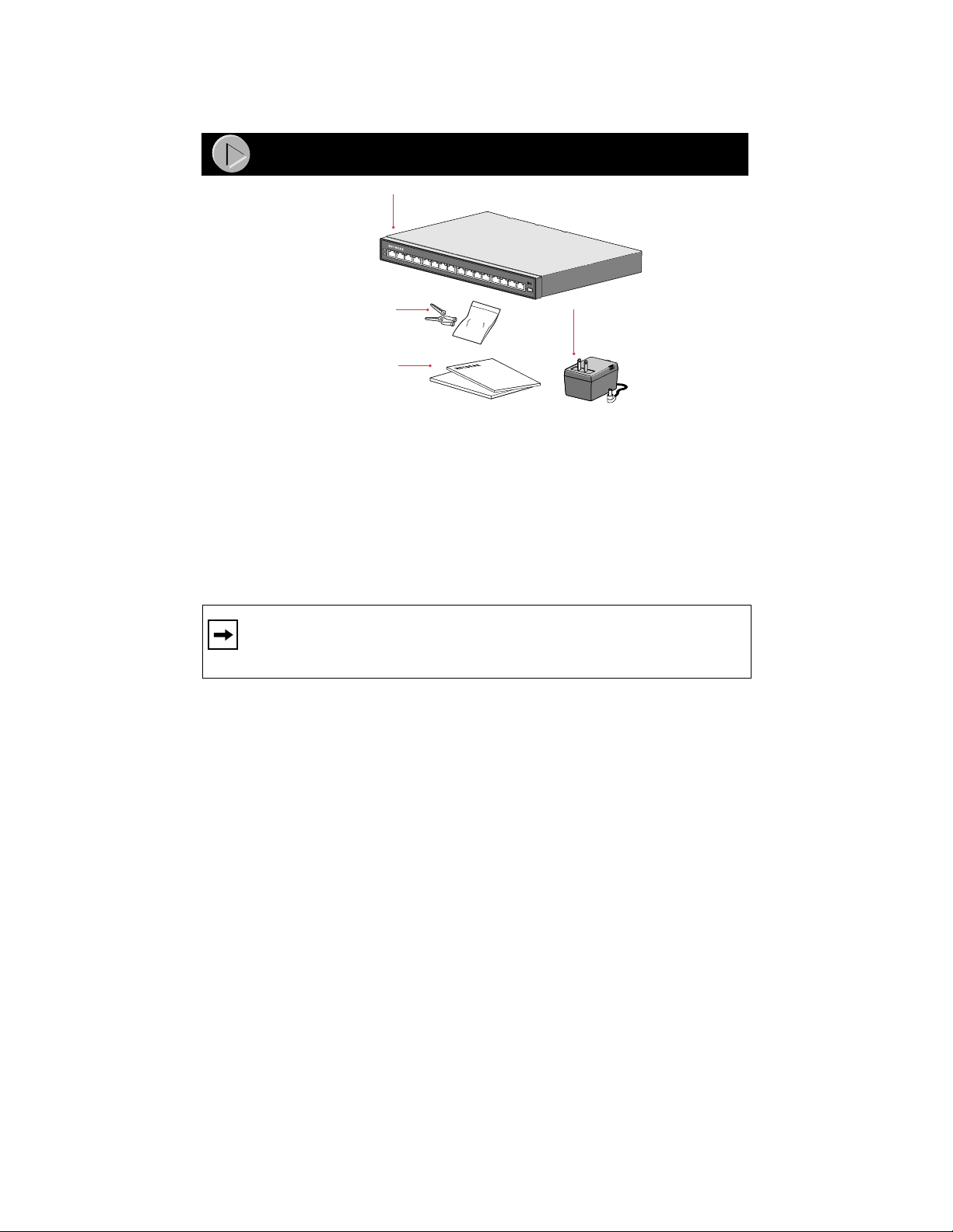
Package Contents
Model FE116 hub
Pwr
Col
1
2
3
4
5
6
7
8
9
10
11
12
13
14
15
16
Wall mount
kit
Installation guide,
Warranty & Owner
Registration Card
Verify that your package contains the following:
• Model FE116 hub
• Power adapter
• Installation guide
• Warranty & Owner Registration Card
Wall mount kit
Normal/Uplink
Power
adapter
8498FA
Note:
If the supplied power adapter does not meet your country
requirements, make sure you use the appropriate power adapter as
required by your national electrical codes and ordinances.
Customer Support
Call your reseller or customer support in your area if there are any wrong,
missing, or damaged parts.
Keep the carton, including the original packing materials. Use them to repack
the hub if you need to return it for repair.
To qualify for product updates and product warranty registration, complete the
Warranty & Owner Registration Card within 30 days of purchase and return it to
NETGEAR, Inc.
M-FE116NA-1 QCARD
Page 4
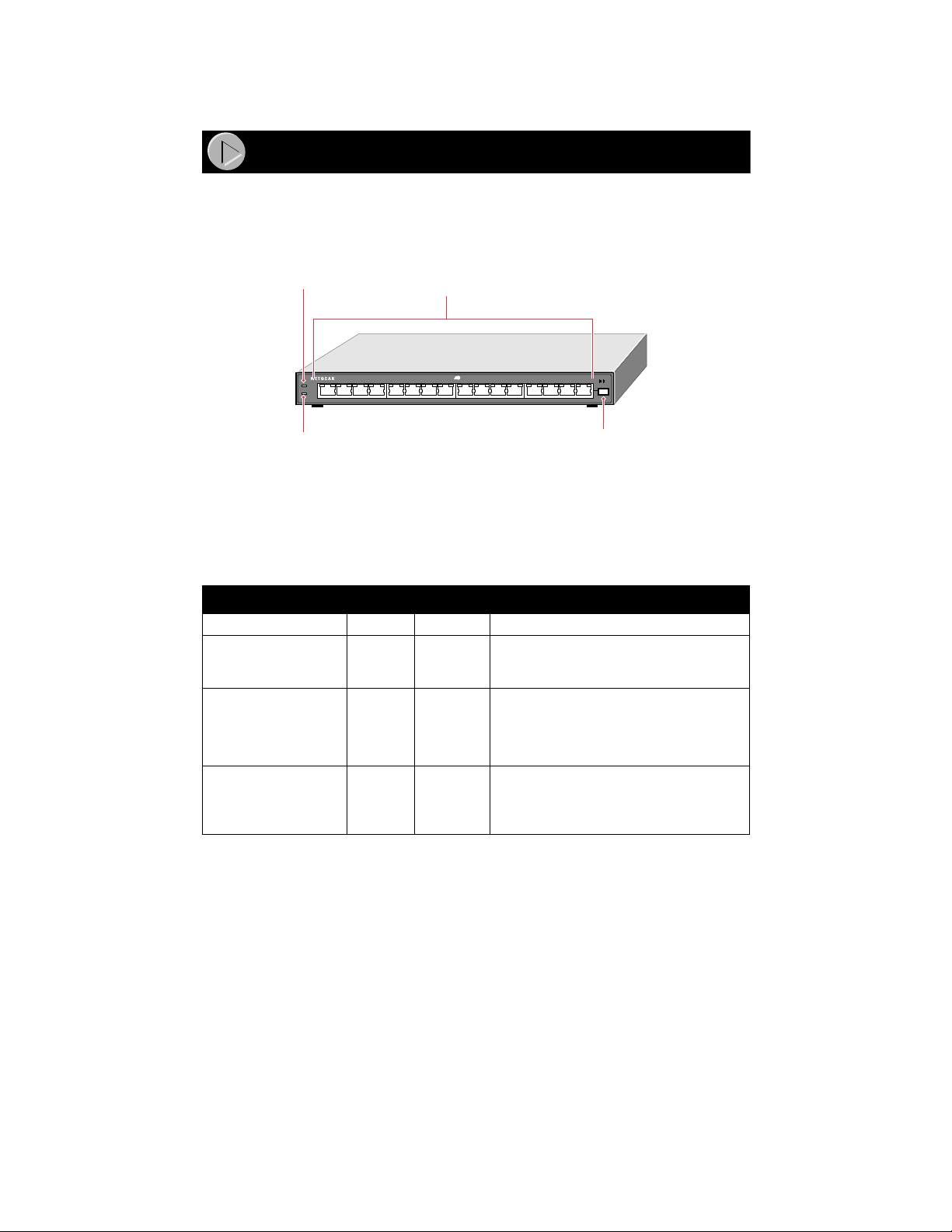
Product Illustration
The instructions provided in this guide are for installing and using the Model
FE116 hub
.
Front Panel of the Model FE116 Hub
Pwr LED
100BASE-FAST ETHERNET HUBFE116
Pwr
Col
1234 1234 9101112 13 14 15 16
Col LED
vista 100BASE-T
network ports
100 Mbps
FAST
Link/Rx Part
Normal/Uplink
Normal/Uplink
push button
8493FA
LEDs
There are two LEDs on the front panel of the hub and two on each vista
100BASE-T network port (RJ-45 connector) that allo w you to monitor the status
of the hub and the network. The table describes the activity of the LEDs.
Label Color Activity Description
Pwr (power) Green On Power is supplied to the hub.
Col (collision) Amber Blinking Data collision is occurring on the
Link/Rx (Located on
Green On
the top left corner
of each vista network
port)
Part (partition)
Amber On The port is partitioned because of
Blinking
(Located on the top
right corner of each
vista network port)
network. Note that occasional collisions
are normal.
The link between this port and the
connected device is good.
There is incoming data on the port.
excessive collisions.
M-FE116NA-1 QCARD
Page 5
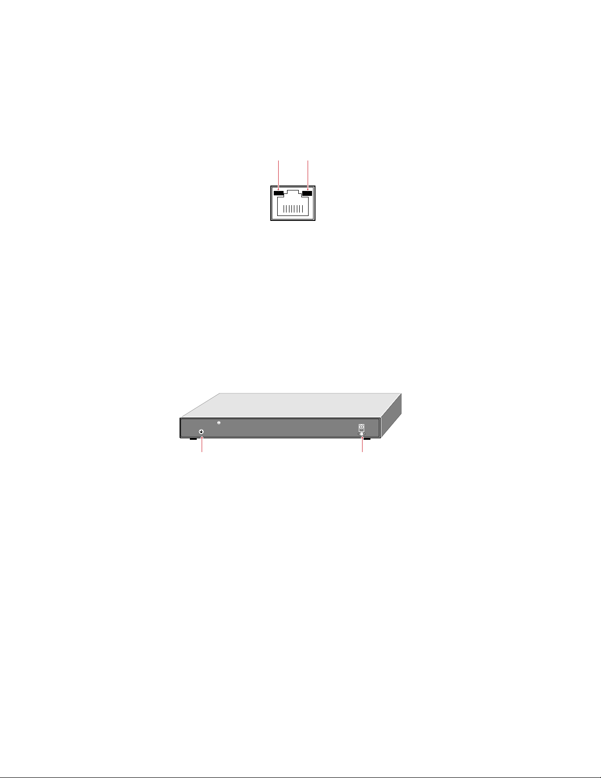
Vista 100BASE-T Network Ports with Built-in LEDs
The front panel of the Model FE116 hub has sixteen vista 100BASE-T ports.
T w o LEDs—the Link/Rx LED and the P art (partition) LED—are b uilt into each
100BASE-T port.
vista 100BASE-T
network port
Link/Rx
LED
Part
LED
8494FA
Normal/Uplink Push Button
The Normal/Uplink push button on the Model FE116 hub allows you to select
Normal (MDI-X) or Uplink (MDI) wiring for port 16, eliminating the need to
use a crossover cable. Ports 1 to 15 on the hub are permanently configured for
Normal wiring.
Rear Panel
The rear panel of the Model FE116 hub has a DC power jack and a ground clip
(not used). The Model FE116 hub accepts 5 V DC.
Rear Panel of the Model FE116 Hub
100 BASE-TX Class
Ground clip
5Vdc 3.0A
– +
Power
jack
8495FA
M-FE116NA-1 QCARD
Page 6

Installation Procedures
Prepare the Site
Before you begin installing the hub, prepare the installation site. Make sure your
operating environment meets the operating environment requirements of the
equipment.
Characteristic Requirement
Temperature Ambient temperature between 0 ° and 40 ° C (32 ° and
Operating humidity 90% maximum relative humidity, noncondensing.
Ventilation Minimum 2 inches (5.08 cm) on all sides for cooling.
Operating conditions At least 6 feet (1.83 m) to nearest source of
Service access Minimum 12 inches (19.68 cm) front and back for service
Power Adequate power source within 6 feet (1.83 m).
Wiring hardware Wiring hardware, such as punchdown blocks or patch
104 ° F).
No nearby heat sources such as direct sunlight, warm air
exhausts, or heaters.
Adequate airflow in room or wiring closet.
electromagnetic noise (such as photocopy machine or arc
welder).
access and maintenance.
Front and back clearance for cables and wiring hardware
such as punchdown blocks.
panels, should be complete before installing the hub.
Installation
Place the Model FE116 hub on a flat surface or mount it on a wall with the
hardware included in the wall mount kit. Be sure the hub is positioned with at
least 2 inches of space on all sides for ventilation.
Connecting Devices
You can connect any device equipped with a 100BASE-T Ethernet interface to
the RJ-45 ports on the Model FE116 hub. These standard RJ-45 ports accept
either 2-pair or 4-pair Category 5 UTP cable (100BASE-TX networks require
only 2-pair wiring). The RJ-45 interface is an 8-pin connector.
To connect any of the RJ-45 ports on your Model FE116 hub to a PC, use a
regular straight-through UTP cable. If you are connecting using Port 16 on your
hub, set the Normal/Uplink push button to Normal.
M-FE116NA-1 QCARD
Page 7

Pwr
Col
1
2
3
4
5
6
7
8
9
10
11
12
13
Normal/Uplink
14
15
16
8496FA
Note:
Ethernet specifications limit the cable length between your
PC or server and the hub to 328 feet (100 meters) in length.
Connect the Hub to a Network
Cascading refers to connecting hubs together to increase the number of ports or
the number of users supported on the network. The 100BASE-T ports can be
used to cascade hubs together.
Connect to a Network Using the 100BASE-T Ports
The twisted pair cable extended from a 100BASE-T port is called a twisted pair
segment and can be up to 100 meters (m) in length. The 100BASE-T ports, with
the exception of port 16, are MDI-X (or Normal) ports. If you are connecting to
ports 1 through 15, use either a straight-through or crossover cable as outlined in
the following table.
Connecting Port on
Model FE116 Hub
Ports 1–15 PC or server Straight-through cable
Ports 1–15 Hub, router, or switch Crossover cable
Set the Normal/Uplink Push Button
If you are connecting to port 16, use this table to determine the type of cable to
use and how to set the Normal/Uplink push button for port 16.
Connecting Port on
Model FE116 Hub
Port 16 set to Normal PC or server Straight-through cable
Port 16 set to Uplink Hub, router, or switch Straight-through cable
Connecting Device Cable Used
Connecting Device Cable Used
You can cascade hubs together through any of the ports. The following
illustration shows cascading two hubs together daisy-chain style and cascading
hubs together in a hierarchical star through the 100BASE-T ports.
M-FE116NA-1 QCARD
Page 8

Two Model FE116 hubs daisy-chained
100 Mbps
100BASE-FAST ETHERNET HUBFE116
Pwr
Col
12341234 9101112 13 14 15 16
100BASE-FAST ETHERNET HUBFE116
Pwr
Col
12341234 9101112 13 14 15 16
Network with Model FE116 hubs
FAST
100 Mbps
FAST
Server
Link/Rx Part
Normal/Uplink
Link/Rx Part
Normal/Uplink
*
Model FS104
10/100 Mbps switch
* Model FE116 hub
100 Mbps
100BASE-FAST ETHERNET HUBFE116
Pwr
Col
12341234 9101112 13 14 15 16
FAST
PCs
* Model FE116 hub
100BASE-FAST ETHERNET HUBFE116
Pwr
Col
12341234 9101112 13 14 15 16
PCs
* Model FE116 hub
100 Mbps
PCs
FAST
Link/Rx Part
Normal/Uplink
8497FA
Link/Rx Part
Normal/Uplink
100 Mbps
FAST
Link/Rx Part
Normal/Uplink
100BASE-FAST ETHERNET HUBFE116
Pwr
Col
12341234 9101112 13 14 15 16
(
* Normal/Uplink push button
in Uplink position)
M-FE116NA-1 QCARD
Page 9

Verify the Installation
5
T o complete the installation, connect the po wer adapter first to the po wer jack on
the hub rear panel and then to the power outlet on the wall. When power has
been applied to the hub:
• The green Pwr (power) LED on the front panel is on.
• The green Link/Rx LED on each connected port is on.
• The green Link/Rx LED on each connected port is blinking when data is
being received by that port.
If there are any problems, refer to “Troubleshooting Information.”
Troubleshooting Information
Refer to this table and the information that follows the table to troubleshoot your
Model FE116 hub.
Symptom Cause Solution
Amber Col (collision) LED
blinks.
Amber Col LED blinks
excessively.
Data collision is normal on
Ethernet networks.
There is data collision on
the network because the
network is extremely busy
or defective devices are
connected on the network
that cannot detect network
traffic or collision.
Wrong or miswired cables
are used.
No action is required.
Make sure connected
devices are operating in
half-duplex mode. The
Model FE116 hub is not
compatible with devices that
operate in full-duplex mode.
If you suspect that there
might be a defective device
on the network, disconnect
devices one at a time to
isolate the defective unit on
the network.
If the network is extremely
busy, you may have to
segment the network with a
Fast Ethernet switch such
as the NETGEAR Model
FS104 switch.
Make sure the correct UTP
cables are used. See the
table in the installation
section of this guide for
cable use and Normal/
Uplink push button
information. Note that home
telephone cables can cause
a collision condition and
cannot be used in place of
UTP cables.
M-FE116NA-1 QCARD
Page 10

Symptom Cause Solution
Amber Part LED turns on. The connected port is
Green Link/Rx LED on the
100BASE-T port is off when
a cable is attached or not
blinking when there is data
transmission.
partitioned because of
excessive collisions.
The port is not detecting a
successful link or data
transmission.
The 100BASE-T RJ-45 port
is partitioned after 32
consecutive collisions are
detected. When the first
good packet without a
collision is received, the
port is reconnected and the
amber Partition LED turns
off. Check and correct
causes listed in this table for
excessive collisions and
make sure that:
The correct cable is used
and the cable is not faulty.
There are no faulty
connectors.
The network card in your
PC is set to half-duplex
mode.
Check for a bad cable , cable
pairs that are not correctly
wired, or loose connectors.
Make sure that there is
power to the hub and the
connected PC. Make sure
the port has not been
partitioned.
Make sure the network card
in the connected PC is
configured for 100 Mbps
operation.
If the Green Link/Rx LED is
on port 16, also check to
make sure the Normal/
Uplink push button switch is
set according to the
instructions in “Installation
Procedures.”
Make sure the network interface cards installed in the workstations are in
working condition and the software driver has been installed.
If required, verify the integrity of the hub by resetting it. Turn power to the
switch off and then back on. If the problem continues and you have completed
all the preceding diagnoses, contact NETGEAR Customer Support. For the
phone number of the representative in your area, see “Customer Support.”
Fast Ethernet Technology
Fast Ethernet is conventional Ethernet but faster. Fast Ethernet, or 100BASETX, operates at 100 Mbps instead of 10 Mbps. The 100BASE-TX technology
uses the same frame format and length as Ethernet and does not require changes
to the upper-layer protocols, applications, or networking software that run on
M-FE116NA-1 QCARD
Page 11

LAN workstations. If your network is migrating from 10 to 100 Mbps, you can
switch and route data from 10 Mbps to 100 Mbps without protocol translation
and its associated delays. Fast Ethernet is based on the proven CSMA/CD
Media Access Control (MAC) Protocol.
The most popular cabling scheme in an Ethernet network today is star-wired
topology, where the hub is in a central wiring closet and individual cables run
out to each tabletop device. This topology is the same topology used by Fast
Ethernet, although the maximum allowable network diameter is smaller because
of the increase in packet speed.
Cable Guidelines for Fast Ethernet
Fast Ethernet uses UTP cable, as specified in the IEEE 802.3u standard for
100BASE-T. The specification recommends Category 5 UTP cable consisting of
either 2-pair or 4-pair twisted insulated copper conductors bound in a single
plastic sheath. Category 5 cable is certified up to 100 MHz bandwidth.
100BASE-TX operation uses one pair of wires for transmission and the other
pair for receiving.
When installing Category 5 UTP cabling, use the following guidelines to ensure
that your cables perform to the following specifications:
• Certification
Make sure that your Category 5 UTP cable has completed the Underwriters
Laboratories (UL) or Electronic Testing Laboratories (ETL) certification
process.
• Termination method
To minimize crosstalk noise, maintain the twist ratio of the cable up to the
point of termination; untwist at any RJ-45 connector or patch panel should
not exceed 0.5 inch (1.5 cm).
Cable Lengths for Fast Ethernet
Category 5 distributed cable that meets ANSI/EIA/TIA-568-A building wiring
standards can be a maximum of 328 feet (100 m) in length, divided as follows:
• 20 feet (6 m) between the hub and the patch panel (if used)
• 295 feet (90 m) from the wiring closet to the wall outlet
• 10 feet (3 m) from the wall outlet to the desktop device
The patch panel and other connecting hardware must meet the requirements for
100 Mbps operation (Category 5). Workmanship quality is a must. Only 0.5 inch
(1.5 cm) of untwist in the wire pair is allowed at any termination point.
M-FE116NA-1 QCARD
Page 12

Technical Specifications
General Specifications
Network Protocol and Standards Compatibility
IEEE 802.3u, 100BASE-TX, Fast Ethernet
IEEE 802.3 CSMA/CD
Data Rate
100 Mbps with 4B/5B encoding and MLT-3 physical interface
Interface
16 100BASE-T network ports (RJ-45)
Power Specifications
Input voltage 100 to 240 VAC, 50 to 60 Hz
Output voltage 5V DC at 3.0 Amps, maximum
Power Consumption 13 W
Physical Specifications
Width: 11.2 inches (28.5 cm)
Height: 1.1 inches (2.8 cm)
Depth: 4.0 inches (10.1 cm)
Weight: 1.61 lb (0.73 kg)
Environmental Specifications
Operating temperature: 0
Operating humidity: 90% maximum relative humidity,
Electromagnetic Emissions
CE mark, commercial
FCC Part 15 Class A
EN 55 022 (CISPR 22), Class A
VCCI Class A ITE
Safety Agency Approvals, Power Adapter
CE mark, commercial
UL listed (UL 1950)
cUL listed
CSA certified (CSA 22.2 #950)
TUV licensed (EN 60 950)
T-Mark
Warranty Information
Hub 5 years
Power adapter 1 year
° to 40
° C (32
noncondensing
° to 104
° F)
M-FE116NA-1 QCARD
Page 13

© 2000 by NETGEAR, Inc. All rights reserved.
Trademarks
NETGEAR™ is a trademark of NETGEAR, INC. Windows® is a registered trademark of Microsoft Corporation. Other brand and product names
are trademarks or registered trademarks of their respective holders. Information is subject to change without notice. All rights reserved.
Statement of Conditions
In the interest of improving internal design, operational function, and/or reliability, NETGEAR reserves the right to make changes to the products
described in this document without notice.
NETGEAR does not assume any liability that may occur due to the use or application of the product(s) or circuit layout(s) described herein.
Certificate of the Manufacturer/Importer
It is hereby certified that the Model FE116 Fast Ethernet Hub has been suppressed in accordance with the conditions set out in the BMPTAmtsblVfg 243/1991 and Vfg 46/1992. The operation of some equipment (for example, test transmitters) in accordance with the regulations may,
however, be subject to certain restrictions. Please refer to the notes in the operating instructions.
Federal Office for T elecommunications Approvals has been notified of the placing of this equipment on the market and has been granted the right to
test the series for compliance with the regulations.
Voluntary Control Council for Interference (VCCI) Statement
This equipment is in the first category (information equipment to be used in commercial and/or industrial areas) and conforms to the standards set
by the Voluntary Control Council for Interference by Data Processing Equipment and Electronic Office Machines that are aimed at preventing radio
interference in commercial and/or industrial areas.
Consequently, when this equipment is used in a residential area or in an adjacent area thereto, radio interference may be caused to equipment such
as radios and TV receivers.
Federal Communications Commission (FCC) Compliance Notice: Radio Frequency Notice
Note: This equipment has been tested and found to comply with the limits for a Class A digital device, pursuant to Part 15 of the FCC rules. These
limits are designed to provide reasonable protection against harmful interference when the equipment is operated in a commercial environment.
This equipment generates, uses, and can radiate radio frequency energy. If it is not installed and used in accordance with the instruction manual, it
may cause harmful interference to radio communications. Operation of this equipment in a residential area is likely to cause harmful interference,
in which case users will be required to take whatever measures may be necessary to correct the interference at their own expense.
EN 55 022 Statement
This is to certify that the Model FE116 Fast Ethernet Hub is shielded against the generation of radio interference in accordance with the application
of Council Directive 89/336/EEC, Article 4a. Conformity is declared by the application of EN 55 022 Class A (CISPR 22).
This is a Class A product. In a domestic environment, this product may cause radio
interference, in which case, the user may be required to take appropriate measures.
Canadian Department of Communications Radio Interference Regulations
This digital apparatus Model FE116 Fast Ethernet Hub does not exceed the Class A limits for radio-noise emissions from digital apparatus as set
out in the Radio Interference Regulations of the Canadian Department of Communications.
Règlement sur le brouillage radioélectrique du ministère des Communications
Cet appareil numérique Model FE116 Fast Ethernet Hub respecte les limites de bruits radioélectriques visant les appareils numériques de classe A
prescrites dans le Règlement sur le brouillage radioélectrique du ministère des Communications du Canada.
M-FE116NA-1 QCARD
Page 14

NETGEAR, Inc.
.
4500 Great America Parkway
Santa Clara, CA 95054
USA
Phone: 1-888-NETGEAR
E-mail: support@netgear.com
www.netgear.com
Customer Support
Phone
Australia: 1-800-787-638 Korea: 00308-11-0319
Austria: 00800-06384327 Netherlands: 0800-023-0981
(00800-0-NETGEAR) New Zealand: 00800-1233-4566
Denmark: 808-82179 Norway: 800-12041
Canada:: 1-888-NETGEAR Singapore: 001-800-1233-4566
Finland: 0800-111-036 Sweden: 0200-298-298
France: 0800-77-17-53 Switzerland: 00800-0638-4327
Germany: 00800-06384327 (00800-0-NETGEAR)
(00800-0-NETGEAR) United Kingdom: 020-7216-0014
Hong Kong 001-800-1233-4566 United States: 1-888-NETGEAR
Japan: 0120-66-5402 All Other Countries: +1 801-236-8499
Internet/W orld W ide Web
The NETGEAR web page is at
http://www.netgear.com
*M-FE116NA-1*
*M-FE116NA-1*
M-FE116NA-1 QCARD
Page 15

M-FE116NA-1 QCARD
 Loading...